

Page 1
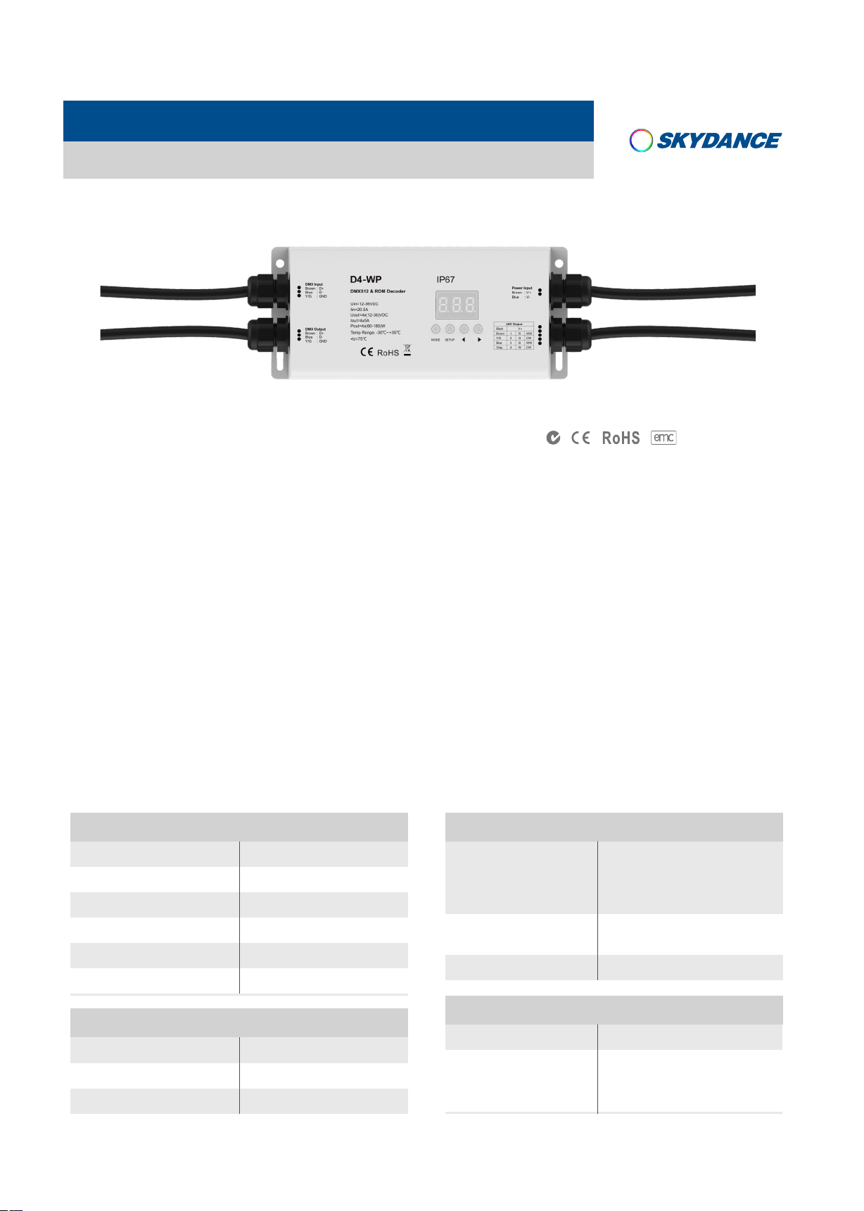
4 Channel Constant Voltage Waterproof DMX512 & RDM Decoder
Model No.: D4-WP
IP67 waterproof/RDM/Stand-alone function/Two PWM frequency/Linear or logarithmic dimming/Numeric display
LVD
Features
● Waterproof DMX512 decoder with IP67 rating, suitable for outdoor and damp environment.
● Comply with the DMX512/RDM standard protocols.
● Digital numeric display, set DMX decode start address by buttons.
● 1/2/4 DMX channel output selectable.
● PWM frequency 2000/500Hz selectable.
● Logarithmic or linear dimming curve selectable.
● Stand-alone RGB/RGBW mode and 4 channel dimmer mode selectable,
which be controlled by buttons with built-in programs, instead of DMX signal.
● Over-heat / Over-load / Short circuit protection, recover automatically.
Technical Parameters
Input and Output
Input voltage
Input current
Output voltage
Output current
Output power
Output type
12-36VDC
20.5A
4 x (12-36)VDC
4CH,5A/CH
4 x (60-180)W
Constant voltage
Safety and EMC
EMC standard (EMC)
Safety standard(LVD)
Certification
EN55032:2015,
EN61000-3-2:2014,
EN61000-3-2:2013,
EN55024 :2010/A1:2015
EN 61347-1:2015
EN 61347-2-11:2015
CE,EMC,LVD
Environment
Operation temperature
Case temperature (Max.)
IP rating
User Manual Ver 1.0.2
Ta: -30OC ~ +55OC
O
+85
T c:
IP67
C
Warranty and Protection
Warranty
Protection
www.iskyda nce.com
5 years
Reverse Polarity
Over-heat
Over-load
Shor t circuit
Page 1
Page 2
D4-WP 4 Channel Constant Voltage Waterproof DMX512 & RDM Decoder
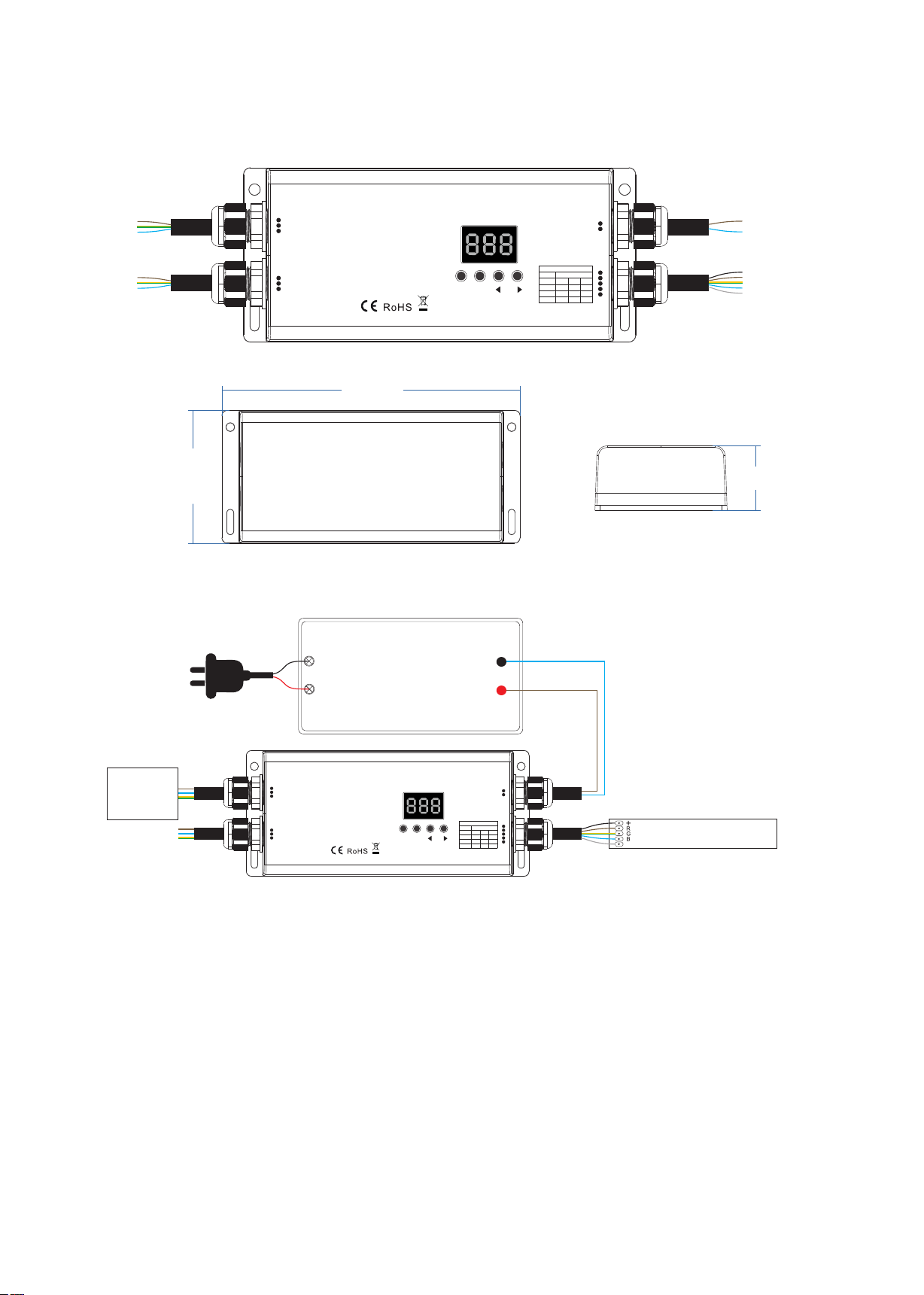
Mechanical Structures and Installations
78.0 mm
Wiring Diagram
AC100-240V
DMX Input
Brown
:D+
:D-
Blue
Y/G
:GND
DMX Output
:D+
Brown
:D-
Blue
:GND
Y/G
D4-WP
DMX512 & RDM Decoder
Uin=12-36VDC
Iin=20.5A
Uout=4x(12-36)VDC
Iout=4x5A
Pout=4x(60-180)W
Temp Range: -30℃~+55℃
•tc=75℃
IP67
MODE SETUP
176.0 m m
Power Supply
12-36VDC
Constant Voltage
Power Input
Brown :V+
Blue :V-
LED Output
Black
V+
Brown
R
WW
1
Y/G
G
CW
2
Blue
3
B
WW
Gray
W
4
CW
38.0 mm
DMX
Master
DMX Input
Brown
Blue
Y/G
DMX Output
Brown
Blue
Y/G
:D+
:D-
:GND
:D+
:D-
:GND
D4-WP
DMX512 & RDM Decoder
Uin=12-36VDC
Iin=20.5A
Uout=4x(12-36)VDC
Iout=4x5A
Pout=4x(60-180)W
Temp Range: -30℃~+55℃
•tc=75℃
IP67
MODE SETUP
Power Input
Brown :V+
Blue :V-
LED Output
Black
V+
Brown
R
WW
1
Y/G
G
CW
2
Blue
3
B
WW
Gray
W
4
CW
RGBW LE D strip
W
Operation
System parameter setting
● Long press SETUP key for 2s, prepare for setup system parameter:
decode mode, output PWM frequence, output brightness curve, automatic blank screen.
then short press SETUP key to switch four item.
● Decode mode: short press ◀ or ▶ key to switch 1/2/4 channel decode mode("d-1","d-2" or "d-4"). When set as 1 channel
decode, the decoder occupy only 1 DMX address, and four channel output the same brightness of this DMX address.
● Output PWM frequence: short press ◀ or ▶ key to switch 500Hz("F-L") or 2KHz("F-H").
Higher PWM frequency, will cause lower output current, higher power noise, but more suitable for camera(No flickers for video).
● Output brightness curve: short press ◀ or ▶ key to switch linear curve("C-L") or logarithmic curve("C-E").
● Automatic blank screen: short press ◀ or ▶ key to switch enable ("bon") or disable("boF") automatic blank screen.
● Long press SETUP key for 2s or timeout 10s, quit system parameter setting.
User Manual Ver 1.0.2
www.iskyda nce.com
Page 2
Page 3
D4-WP 4 Channel Constant Voltage Waterproof DMX512 & RDM Decoder
DMX mode
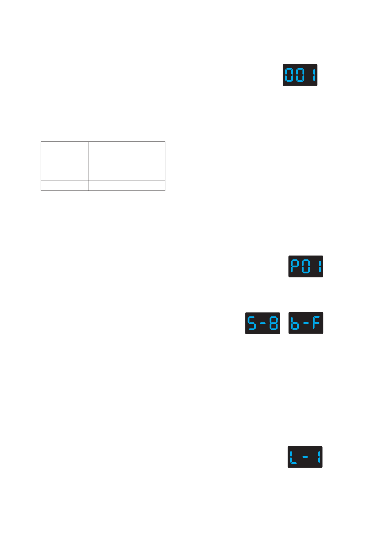
● Short press MODE key, when display 001~999, enter DMX mode.
● Press ◀ or ▶ key to change DMX decode start address(001~999),
long press for fast adjustment.
● If there is a DMX signal input, will enter DMX mode automatically.
DMX mode
● DMX Dimming: Each D4-WP DMX decoder occupy 4 DMX address
when connecting the DMX console.
For example, the defaulted start address is 1,
their corresponding relationship in the form:
DMX Console
CH1 0-255
CH2 0-255
CH3 0-255
CH4 0-255
DMX Decoder Output
CH1 PWM 0-100% (LED R)
CH2 PWM 0-100% (LED G)
CH3 PWM 0-100% (LED B)
CH4 PWM 0-100% (LED W)
Stand-alone RGB/RGBW mode
● Enter stand-alone RGB/RGBW mode only when DMX signal is disconnected or lost.
● Short press MODE key, when display P01~P30, enter stand-alone RGB/RGBW mode.
● Press ◀ or ▶ key to change dynamic mode number(P01~P30).
● Each mode can adjust speed and brightness.
Short press SETUP key for switch between mode speed,
brightness and W channel brightness setting.
Press ◀ or ▶ key to setup value of each item.
Mode speed: 1-10 level speed(S-1, S-9, S-F).
Mode brightness: 1-10 level brightness(b-1, b-9, b-F).
W channel brightness: 0-255 level brightness(400-4FF).
Long press SETUP key for 2s, or timeout 10s, quit setting.
Stand-alone RGB/RGBW mode
Speed
(8 level)
(001~999)
(P01~P30)
Brightness
(10 level,100%)
Stand-alone dimmer mode
● Enter stand-alone dimmer mode only when DMX signal is disconnected or lost.
● Short press MODE key, when display L-1~L-8, enter stand-alone dimmer mode.
● Press ◀ or ▶ key to change dimmer mode number(L-1~L-8).
● Each dimmer mode can adjust each channel brightness independently.
Short press SETUP key to switch between 4 channel(100~1FF, 200~2FF, 300~3FF, 400~4FF).
Press ◀ or ▶ key to setup brightness value of each channel.
Long press SETUP key for 2s, or timeout 10s, quit setting.
User Manual Ver 1.0.2
www.iskyda nce.com
Stand-alone dimmer mode
(L-1~L-8)
Page 3
Page 4
D4-WP 4 Channel Constant Voltage Waterproof DMX512 & RDM Decoder
Restore factory default parameter
● Long press ◀ and ▶ key for 2s, restore factory default parameter, display"RES".
● Factory default parameter: DMX decode mode, DMX decode start address is 1, four channel decode,
high PWM frequence output, logarithmic brightness curve, RGB mode number is 1,
dimmer mode number is 1, disable automatic blank screen.
RGB change mode list
No.
P01
P02
P03
P04
P05
P06
P07
P08
P09
P10
Name
Static red
Static green
Static blue
Static yellow
Static cyan
Static purple
Static white
RGB jump
7 color jump
Red strobe
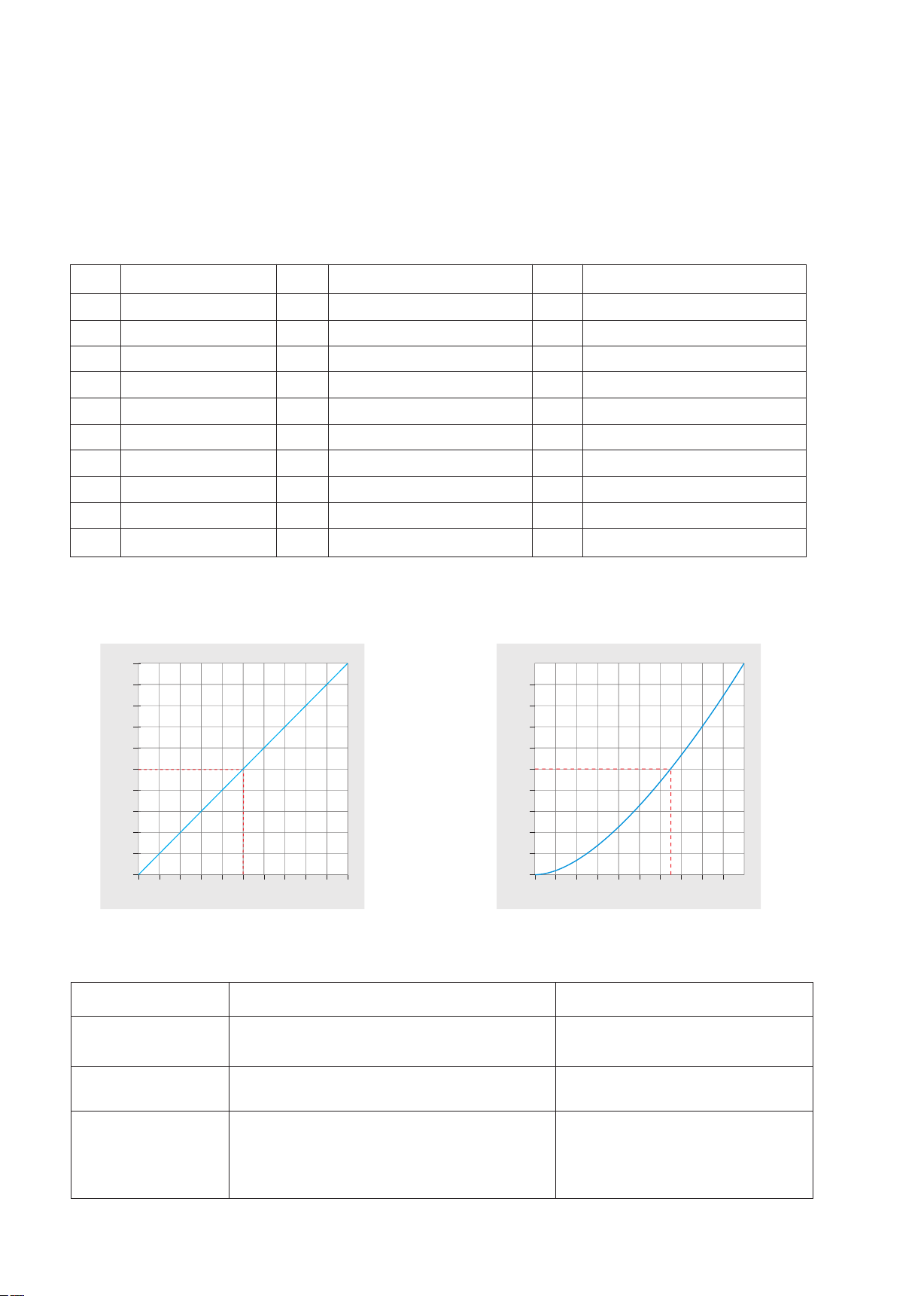
Dimming curve setting
Linear dimming curve
100
100
90
90
80
80
70
70
60
60
50
50
40
40
PWM dut y(%)
PWM dut y(%)
30
30
20
20
10
10
Gamma=1.0
No.
P11
P12
P13
P14
P15
P16
P17
P18
P19
P20
Name
Green strobe
Blue strobe
White strobe
RGB strobe
7 color strobe
Red fade in and out
Green fade in and out
Blue fade in and out
White fade in and out
RGBW fade in and out
No.
P21
P22
P23
P24
P25
P26
P27
P28
P29
P30
Red yellow smooth
Green cyan smooth
Blue purple smooth
Blue white smooth
RGB+W smooth
RGBW smooth
RGBY smooth
Yellow cyan purple smooth
RGB smooth
6 color smooth
Logarithmic dimming curve
100
90
80
70
60
50
40
PWM dut y(%)
30
20
10
Gamma=1.6
Name
10 20 30 40
50 60 70 80 90 100
Brigh tness(%)
Malfunctions analysis & troubleshooting
Malfunctions
No light
Wrong color
Uneven intensity
between front and
rear,with voltage drop
User Manual Ver 1.0.2
1. No power.
2. Wrong connection or insecure.
1. Wrong connection of R/G/B/W wires.
2. DMX decode address error.
1. Output cable is too long.
2. Wire diameter is too small.
3. Overload beyond power supply capability.
4. Overload beyond controller capability.
Causes
www.iskyda nce.com
10 20 30 40
50 60 70 80 90 100
Brigh tness(%)
Troubleshooting
1. Check the power.
2. Check the connection.
1. Reconnect R/G/B/W wires.
2. Set corrrect decode address.
1. Reduce cable or loop supply.
2. Change wider wire.
3. Replace higher power supply.
4. Add power repeater.
Page 4
 Loading...