

Page 1
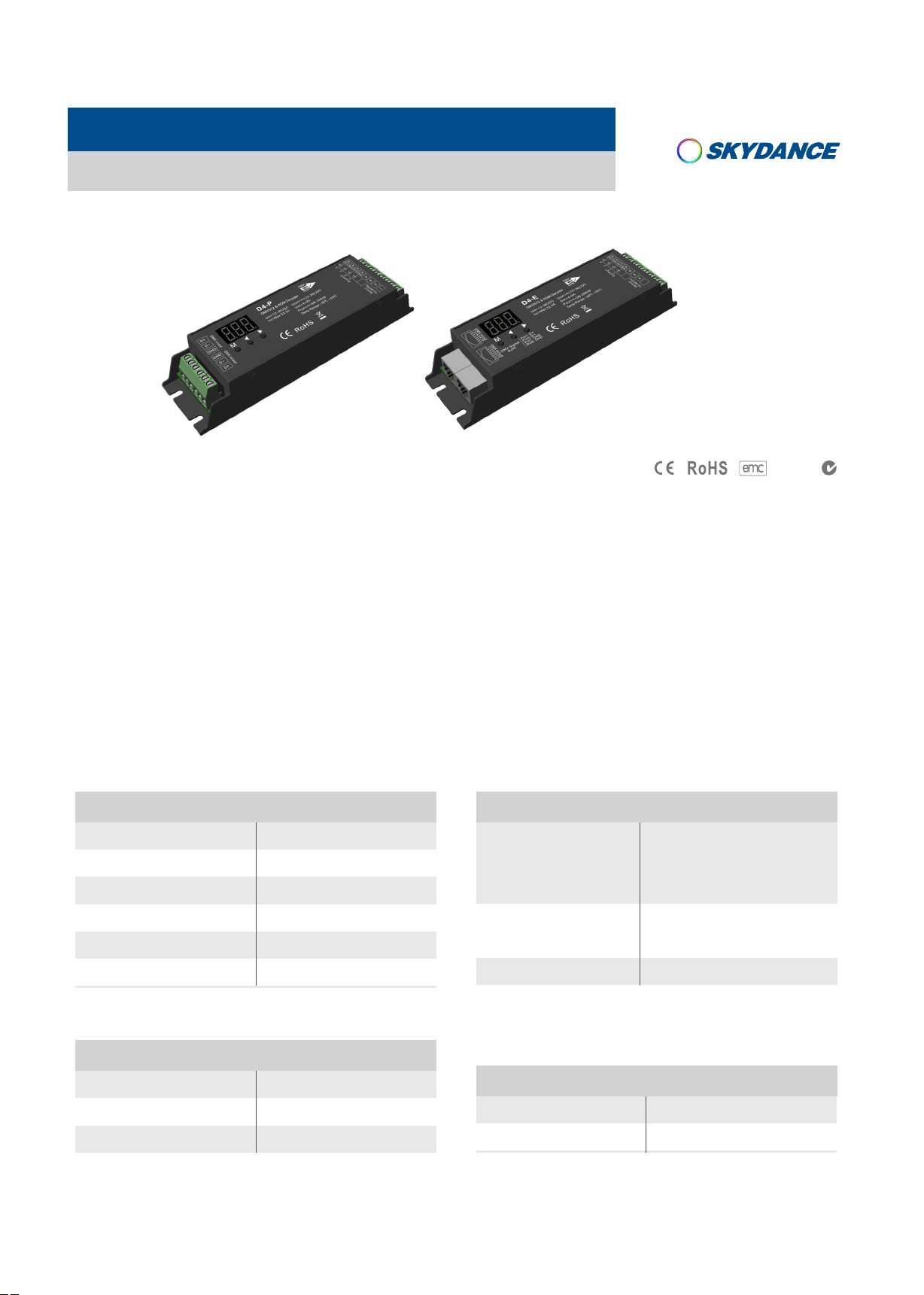
4 Channel Constant Voltage DMX512 & RDM Decoder
Model No.: D4-P / D4-E
RDM/Numeric display/Logarithmic dimming
D4-P D4-E
Features
● Comply with the DMX512 standard protocols.
LVD
● Digital numeric display, set DMX decode start address by bottons.
● RDM function can realize intercommunication between DMX master and decoder.
For example, DMX decoder address can be set by DMX master console.
● D4-P have Green termimal DMX signal ports, D4-E have RJ-45 DMX signal ports.
Technical Parameters
Input and Output
Input voltage
Input current
Output voltage
Output current
Output power
Output type
12-36VDC
32.5A
4 x (12-36)VDC
4CH,8A/CH
4 x (96-288)W
Constant voltage
Safety and EMC
EMC standard (EMC)
Safety standard(LVD)
Certification
EN55032:2015,
EN61000-3-2:2014,
EN61000-3-2:2013,
EN55024 :2010/A1:2015
EN 61347-1:2015
EN 61347-2-11:2015
CE,EMC,LVD
Environment
Operation temperature
Case temperature (Max.)
IP rating
User Manual Ver 1.0.2
Ta: -30OC ~ +55OC
O
+85
T c:
IP20
C
Warranty and Protection
Warranty
Protection Reverse Polarity
www.iskyda nce.com
5 years
Page 1
Page 2
D4-P, D4-E 4 Channel Constant Voltage DMX512 & RDM Decoder
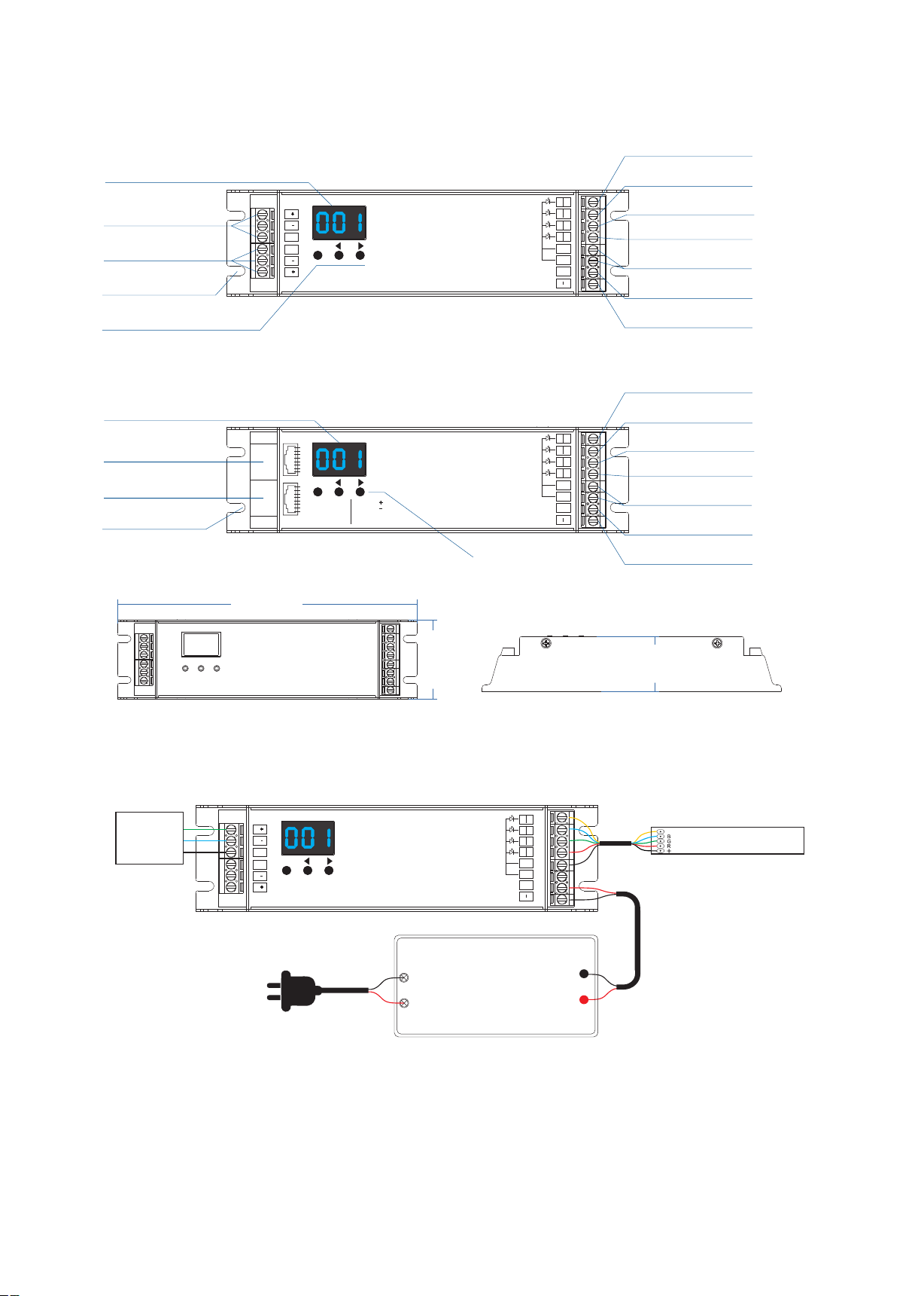
Mechanical Structures and Installations
Output White LED -
Digital dis play
DMX input / output
DMX input / output
Installation rack
Setting key
Digital dis play
DMX input / output
DMX input / output
Installation rack
D
GND
GND
D
175.0 0 mm
D
D
DMX in /out DMX in /out
M
DMX in /out
12 3 4 5 6 7 8
DMX in /out
M
12 3 4 5 6 7 8
DMX S ignal
RJ4 5
Pin 1: D
Pin 2: D
Pin 7: GND
Pin 8: GND
D4-P
D4-E
Setting key
Output Blue LED -
W
CW
4
B
WW
G
CW
R
WW
1 2 3
OUTP UT
+
+
+
IN PUT
12-3 6VDC
Output Green LED -
Output Red LED -
Output LED +
Power input +
Power input -
Output White LED -
Output Blue LED -
W
CW
4
B
WW
G
CW
R
WW
1 2 3
OUTP UT
+
+
+
IN PUT
12-3 6VDC
Output Green LED -
Output Red LED -
Output LED +
Power input +
Power input -
32.00 m m
46.00 m m
Wiring Diagram
W
CW
DMX in /out DMX in /out
DMX
Master
D
D
GND
M
GND
D
D
D4-P
AC100-240V
Power Supply
12-36VDC
Constant Voltage
Note:
1. An DMX signal amplifier is needed if more than 32 decoders are connected, or use overlong signal line,
signal amplification should not be more than 5 times continuously.
2. If the recoil effect occurs because of longer signal line or bad line quality, please try to connect 0.25W
90-120Ω terminal resistor at the end of each DMX signal line.
4
B
WW
G
CW
R
WW
1 2 3
OUTP UT
+
+
+
IN PUT
12-3 6VDC
W
RGBW LE D str ip
User Manual Ver 1.0.2
www.iskyda nce.com
Page 2
Page 3
D4-P, D4-E 4 Channel Constant Voltage DMX512 & RDM Decoder
Operation
DMX mode
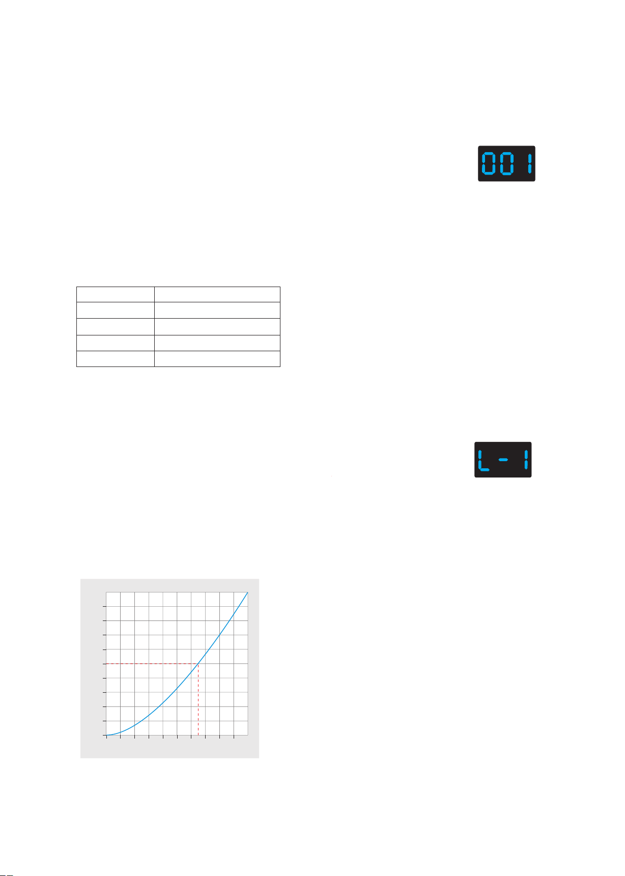
● Short press M key, when display 001~999, enter DMX mode.
● Press ◀ or ▶ key to change DMX decode start address(001~999),
long press for fast adjustment.
● If there is a DMX signal input, will enter DMX mode automatically.
● DMX Dimming: Each D4-P/D4-E DMX decoder occupy 4 DMX address
when connecting the DMX console.
For example, the defaulted start address is 1,
their corresponding relationship in the form:
DMX mode
(001~999)
DMX Console
CH1 0-255
CH2 0-255
CH3 0-255
CH4 0-255
DMX Decoder Output
CH1 PWM 0-100% (LED R)
CH2 PWM 0-100% (LED G)
CH3 PWM 0-100% (LED B)
CH4 PWM 0-100% (LED W)
Self-test mode
● Enter self-test mode only when DMX signal is disconnected or lost.
● Short press M key, when display L-1~L-5, enter self-test mode.
● Press ◀ or ▶ key to change mode number(L-1L-5).
● Self-test mode include four channel light up separately or synchronously.
Dimming curve
100
90
80
70
60
50
40
PWM dut y(%)
30
20
10
Gamma=1.6
Self-test mode
(L-1~L-5)
10 20 30 40
User Manual Ver 1.0.2
50 60 70 80 90 100
Brigh tness(%)
www.iskyda nce.com
Page 3
Page 4
D4-P, D4-E 4 Channel Constant Voltage DMX512 & RDM Decoder
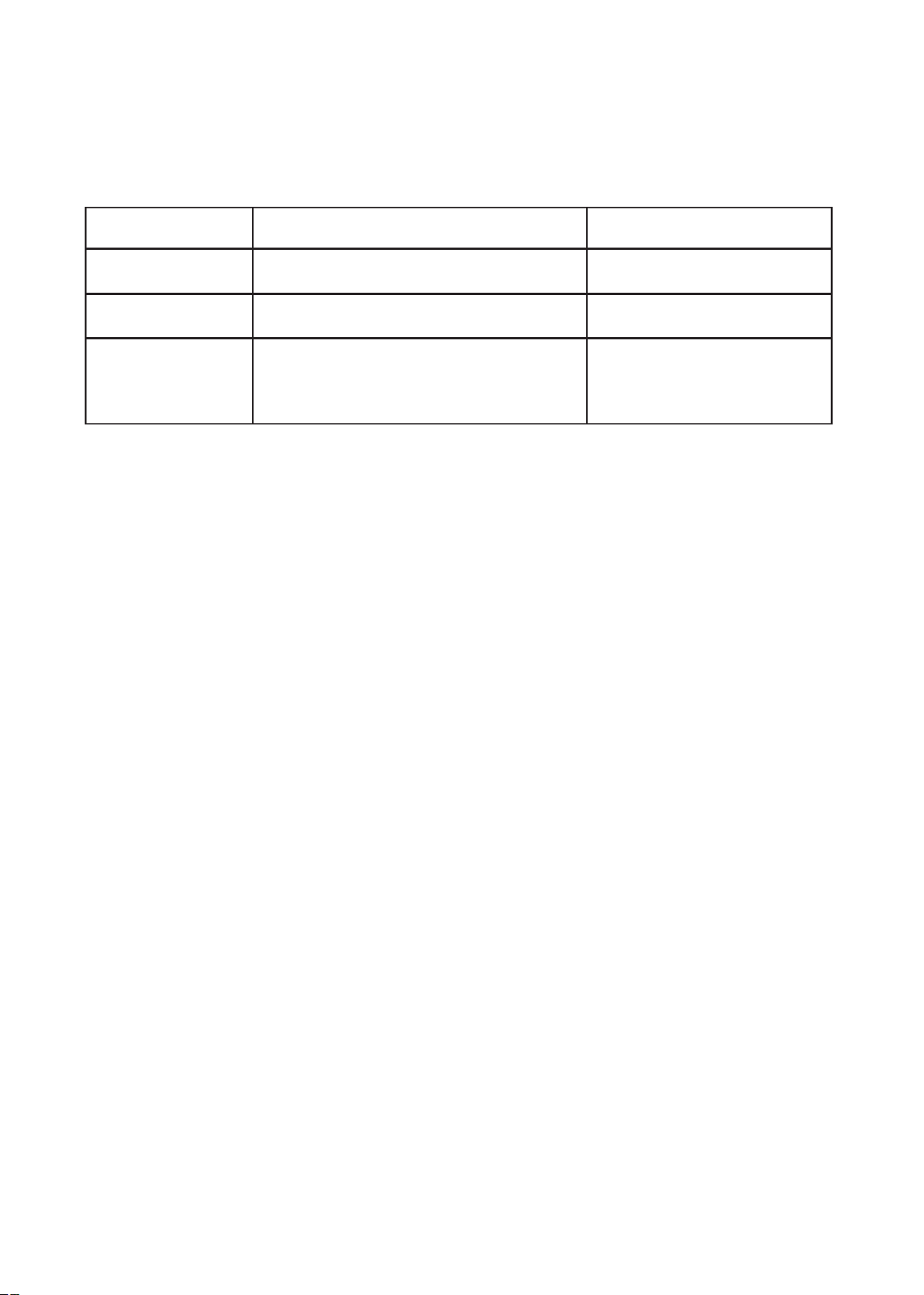
Malfunctions analysis & troubleshooting
Malfunctions
No light
Wrong color
Uneven intensity
between front and
rear,with voltage drop
Causes
1. No power.
2. Wrong connection or insecure.
1. Wrong connection of R/G/B/W wires.
2. DMX decode address error.
1. Output cable is too long.
2. Wire diameter is too small.
3. Overload beyond power supply capability.
4. Overload beyond controller capability.
Troubleshooting
1. Check the power.
2. Check the connection.
1. Reconnect R/G/B/W wires.
2. Set corrrect decode address.
1. Reduce cable or loop supply.
2. Change wider wire.
3. Replace higher power supply.
4. Add power repeater.
User Manual Ver 1.0.2
www.iskyda nce.com
Page 4
 Loading...