

Page 1
1
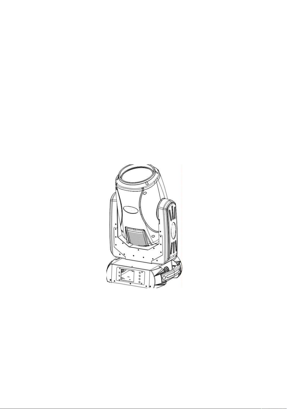
SKY BEAM 9R
USER MANUAL
Please read over this manual before operation the light
Page 2

2
CONTENTS
Chapter 1 Installation and attention .................................................................................................. 3
1. Maintenance ...................................................................................................................... 3
2. Statement ........................................................................................................................... 3
3. Safety Precaution .............................................................................................................. 3
4. Product Instruction ............................................................................................................ 3
5. Cable connection(DMX) .............................................................................................. 4
6. Rigging (Optional) ............................................................................................................ 4
Chapter 2 Panel operation .............................................................................................................. 6
1. Brief .................................................................................................................................. 6
2. Operation ........................................................................................................................... 6
1. Operate light with touch or encoder button ............................................................... 6
2. Parameter value setting ............................................................................................. 6
3. Boolean parameter setting ......................................................................................... 7
4. Sub Menu(Parameter) .......................................................................................... 7
3. Operation and parameter instruction ................................................................................. 7
1. Set DMX Address ..................................................................................................... 8
2. Set Light work mode ................................................................................................. 8
3. Set display ................................................................................................................. 9
4. Test light .................................................................................................................... 9
5. Set light run parameter ............................................................................................ 10
6. View status .............................................................................................................. 10
Chapter 3 Channel description ..................................................................................................... 11
1. Channel table ................................................................................................................... 11
Page 3

Chapter 1 Installation and attention
1. Maintenance
To reduce the risk of electrical shock or fire, do not expose this unit to rain or moisture.
Intermittently using will extend this item’s service life.
Please clear the fan ,fan net , and optical lens in order to keep good work state.
Do not use the alcohol or any other organic solvent to wipe the shell.
2. Statement
The product has perfect performance and integrity packing. All users should be strictly complying
with the warning and operating instructions as stated. Or we aren’t in charge of any result by
misusing. Any damage resulting by misuse is not within the Company’s warranty. Any fault or
problem caused by neglecting the manual is also not in the charge of dealers.
Note: All information is subject to change without prior notice.
3. Safety Precaution
In order to guarantee the product’s life, please don’t put it in the damp places or even the
environment over 60degress.
Always mount this unit in safe and stable matter.
Install or dismantle should operate by professional engineer.
Using lamp,the change rate of power voltage should be within±10%,If the voltage is too
high,it will shorten the light’s life; If it’s not enough, will influence the effect.
Please restart it 20 minutes later after turning off light , until full-cooling. Frequent switching
will reduce the life span of lamps and bulbs; intermittent using will improve the life of bulbs
and lamps.
In order to make sure the product is used well, please read the Manual carefully.
4. Product Instruction
lamp: YODN R9 260W
Channel mode: 18 DMX512 Channel
Pan scan:540°(16bit) Electric correction
Tilt scan:270° (16bit) Electric correction
Amazing dot matix, four tact switch, 180° turning show
Color wheel: one color wheel, 14 kinds of color chips in one color wheel
Gobo: 14 gobos
Effect Wheel: Rotation eight prism, effect move , frost
0-100% mechanical dimming, mechanical dimming and free dimming available
Page 3
Page 4
strobe macro control available.
Lens optical system achanical fouce .beam angle 0~4°
Over heat protection
Power Input: 100-240V,50/60Hz
Power Dissipation:400W
IP level :IP20
Magnetic ballast and AC/Dc power supply
Product Size:45*43*57cm
Packing Size: 69*44*71cm
Net weight:15.5KG
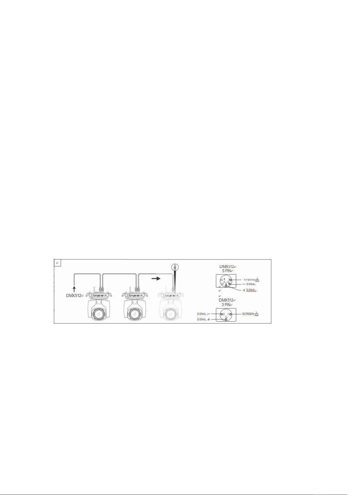
5. Cable connection(DMX)
Use a cable
impedance,
from those specified.
terminating
terminals
IMPORTANT:
The
casing
conforming
22-24 AWG, low
The end
plug
must
be
inserted
2 and 3.
The wires must not make
itself must be
to
specifications
capacity.
connections must
into the last
connected
6. Rigging (Optional)
EIA
Do not use
be
projector
contact
RS-485:
microphone cable
made using
with each other or with the metal
with a
2-pole
twisted, shielded, 120Ohm characteristic
or
other cable
XLR type 3 or
resistance
of
120Ohm (minimum
with
characteristics differing
5-pin male/female connectors.
casing
of the
to the shield braid and to pin 1 of the connectors.
Figure 1 DMX Cable connection
1/4 W)
connectors.
A
between
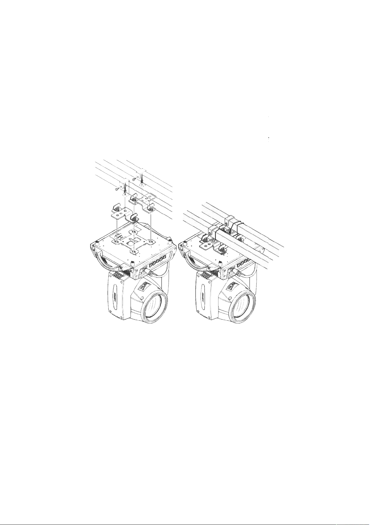
This equipment can be positioned and fixed by clamp in every direction of the stage. Locking
system makes it easy to fasten to the bracket.
Attention! Two clamps is needed to fix the equipment. Every clamp is locked by fastener of 1/4
kind. Fastener can only be locked clockwise.
Attention! Fasten a safety string to the additional hole of side aluminum piece. The secondary
accessory can not hang on the delivery handle. Nip the equipment on bracket.
Check if rigging clamp (not including the one inside) damaged or not? If stand ten times
weight as the equipment. Make sure the architecture can stand ten times weight as all the
Page 4
Page 5
equipments, clamps, wirings and other additional fixtures.
mping must be fixed firmly. Take one M12 screw (Grade 8.8 or higher) to
clamp bracket, and then screw the nuts.
Level the two hanging points at the bottom of clamp. Insert fastener to the bottom, lock the
two levers by 1/4 rotating clockwise; then install
Install on safety string which stands at least ten times weight as equipment. Terminal of the
accessory is designed for clamps.
Make sure pan/tilt lock unlocked or not. Keep the distance more than 1M from equipment to
ighting source.
Screws for cla
flammable material or l
another clamp.
Figure 2 Installation
Page 5
Page 6
Chapter 2 Panel operation
1. Brief
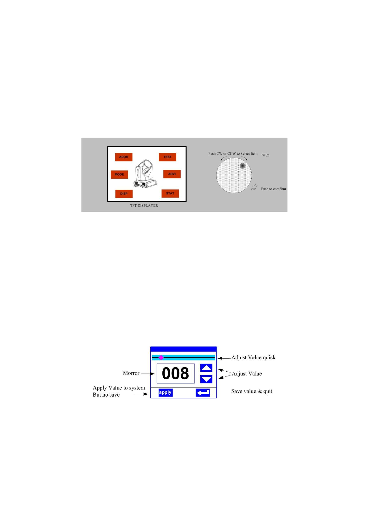
The light panel diagram show as Figure 3, Left area is TFT Displayer, support touch, and right
area is encoder button, both of touch and coder button can operate light and setting.
Display & operation just like ‘Android operation system’, touch the item will set or modify
setting.
Note: Prevent damage the touch or TFT displayer, Can not use sharp objects chick displayer.
Figure 3 Panel diagram
2. Operation
1. Operate light with touch or encoder button
The left area is TFT Displayer and touch, chick item or value with finger will to complete
operation of set light setting(parameters) or view light state.
The area on the right hand side is rotary encoder with button, As auxiliary input interface, if
disable touch function,, the encoder can been choose to set or view the item, and then press
the encoder button to confirm the selection, rotary encoder again set the parameter value,
finally, Press encoder button one again to save value or setting.
2. Parameter value setting
When the selected item is value need to been modified, the dialog shown in Figure 4 will popup.
Figure 4 Dialog of value setting
Modify value:Can quickly modify value via pull the slider to the desired position, or click
the button of ‘up’ or ‘down’ whit finger on the right side to set the exact desired value,
another way is roll encoder on the right hand side of panel.
Apply value:When Value had been modified, Then press the bottom of ‘apply’ in the left
corner to apply to the light, but hav’t saved;
Save Value:Any time, click on the lower right corner of the "OK" button, the setting will
Page 6
Page 7
been saved into internal memory.
3. Boolean parameter setting
when the selected parameters is a Boolean value (such as ON or OFF), can directly modify
setting by chick corresponding item, the setting will been saved right now.
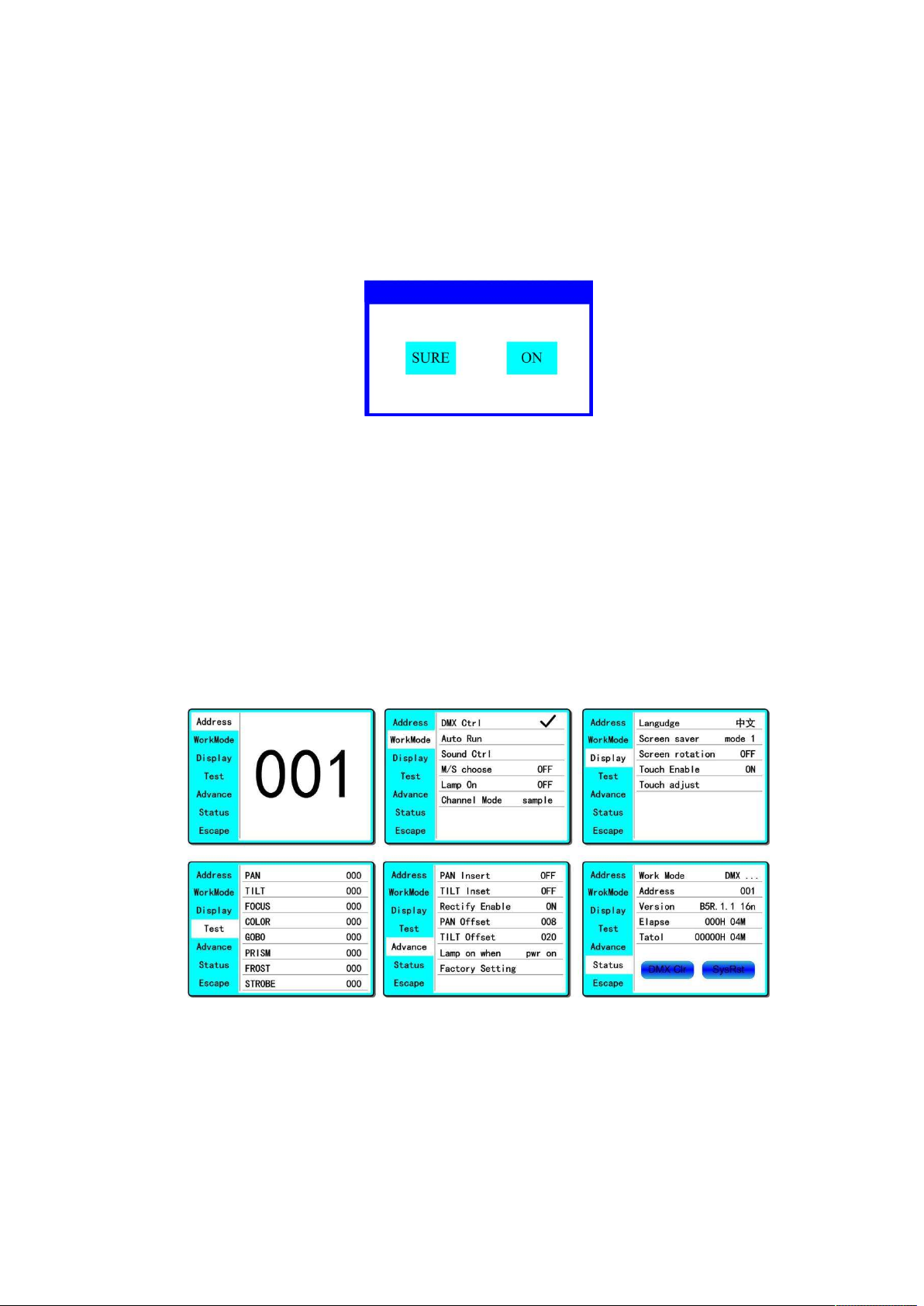
When the parameter is a key item, chick corresponding item, a dialog shown in Figure 5 will
been popup ask for the confirm. Chick ‘sure’ to confirm.
Figure 5 Dialog of confirm
4. Sub Menu(Parameter)
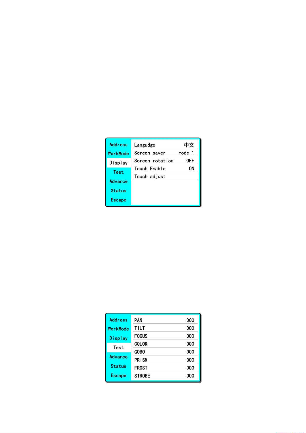
Chick item of main menu, enter corresponding sub menu, shown in Figure 6, total 6 sub menu,
includes class of parameter and status:
ADDRESS:Set light DMX address.
WORKMOD:Set light work mode, master or slave mode when in auto run mode.
DISPLAY: Set display parameter, eg. select language.
TEST:Used for test light, modify DMX channel data to test function, the corresponding
function of reference channel function table.
ADVANCE:Set light running parameter.
STATUS:view light current status.
Figure 6 Parameter menu
3. Operation and parameter instruction
Via following operation, enter sub menu(parameter menu) shown in Figure 6
In main menu, chick 1/6 function button into corresponding parameter menu.
In sub menu(page), chick main item on the left side of displayer, can shift to corresponding
sub menu(page) quickly.
Page 7
Page 8

1. Set DMX Address
Click and select the "ADDR", can enter the page of DMX address setting, range from 1 to 512, the
address code shouldn’t is not greater than (512- channels quantity), otherwise the light will not
been controlled. Following is the operation:
Enter the page of DMX address, as shown in Figure 7, click the blank area in right side of display
will pop-up diglog as in Fig. 4, modify value, then click ‘ENTER’ to confirm and save DMX
address code.
Figure 7 page of DMX Address
2. Set Light work mode
Enter the page of ‘WORK MOD’ as shown in Figure 8 and modify setting. Can set light work
mode, control lamp and DMX channel mode..
Light includes 3 work mode: DMX MODE, AUTO RUN and SOUND MODE, Parameter
definition as following:
DMX Mode:Under this mode, the light receive data from the DMX controller and move.
AUTO RUN:Under this mode, light will run with inside code(data), ignore data from DMX
controller.
SOUND Ctrl:Under this mode, light ignore data from DMX controller., When there is a
strong sound in stage, the light will run a scene, otherwise it will keep the last scene.
M/S Choose:’M/S Choose’ is available when light just in ‘AUTO RUN’ or ‘SOUND Ctrl’
mode. If this item is set as ‘OFF’, the light don’t send data to other light via DMX Cable.
When ‘ON’, the data will send to other slave light immediately.
Lamp control:Turn on lamp when this item is set ‘ON’, otherwise, turn off lamp. The gap
between operation is limited to 30 second.
Channel mode:Light support 2 DMX Channel mode: sample or extend。
Figure 8 page of work mode
Page 8
Page 9
3. Set display
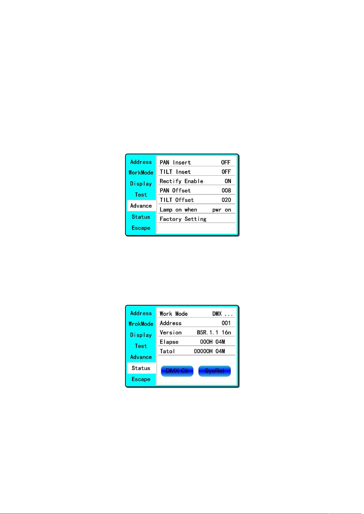
Light support 2 language, rotation display,Enter page as shown in Figure9 to set parameter
following:
Language:Select display as simplified Chinese or English.
Screen Saver:when panel is idle(these is no operation in 10 second), displayer will enter
saver status. When set as ‘mode 1’,saver status is close display, as ‘mode 2’ saver status
will display DMX address code(DMX MODE) or display LOGO(AUTO RUN or SOUND
CTRL). As ‘OFF’, keep light up displayer and show main menu。
Screen Rotation:rotate displayer.
Touch enable:Disable or enable touch function, when disable, use encoder to operate light
and set parameter.
Touch adjust:adjust touch function, normally, not enter this item.
Figure9 page of display
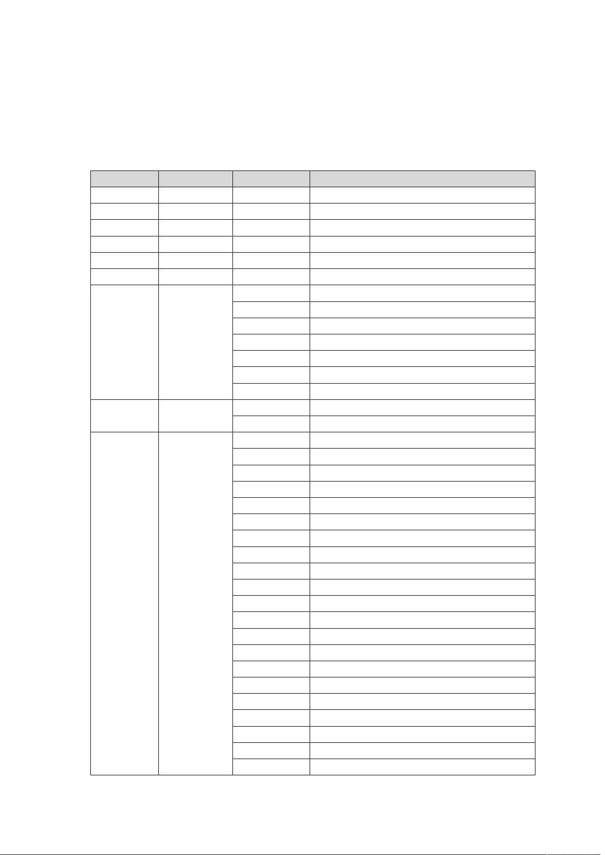
4. Test light
Enter the page as shown in Figure 10, Light will into test mode, in this mode, the light does not
receive the data for DMX controller.:
PAN: range for 0 to 255;
TILT: range for 0 to 255;
FOCUS: range for 0 to 255;
COLOR: range for 0 to 255;
GOBO: range for 0 to 255;
PRISM: range for 0 to 255;
FROST: range for 0 to 255;;
STROBE: range for 0 to 255;。
Figure 10 page of Test
Page 9
Page 10
5. Set light run parameter
Enter the page as shown in Figure 10, set the parameter of light:
Pan Invert: Reverse PAN move.
Tilt Invert: Reverse TILT mover.
Rectify enable:set as ‘OFF’, PAN or TILT will disable position rectify function. As ‘ON’,
when PAN or TILT lose steps, light will rectify auto.
Pan Offset: Set PAN original position.
Tilt Offset: Set TILT original position.
Lamp up when: Select lamp on mode, includes 3 mode: power on, after reset done and
manual;
Factory setting: restore all parameter to factory setting.
Figure 11 page of run parameter
6. View status
Enter the page as shown in Figure 12:
View light current status, version;
DMXClr: Click to clear all DMX data to ‘0’.
SysRst:Click to reset light.
Figure 12 page of status
Page 10
Page 11
Chapter 3 Channel description
1. Channel table
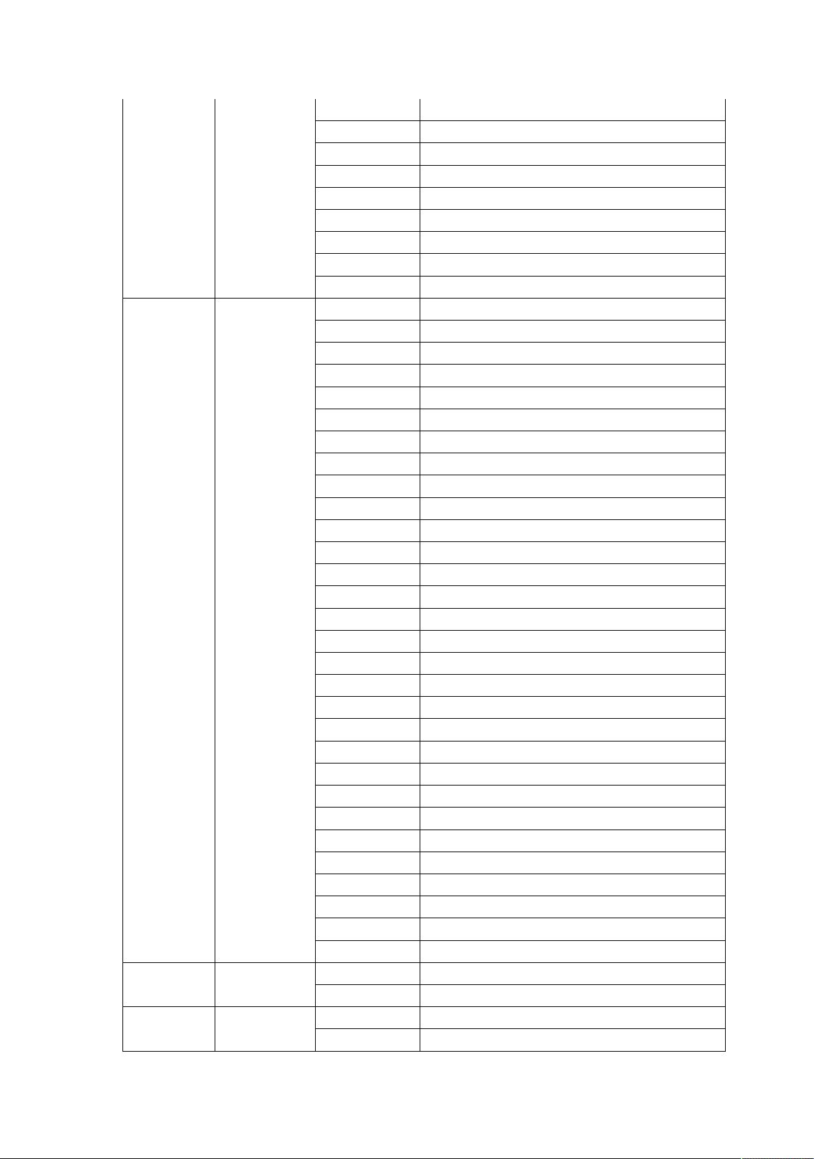
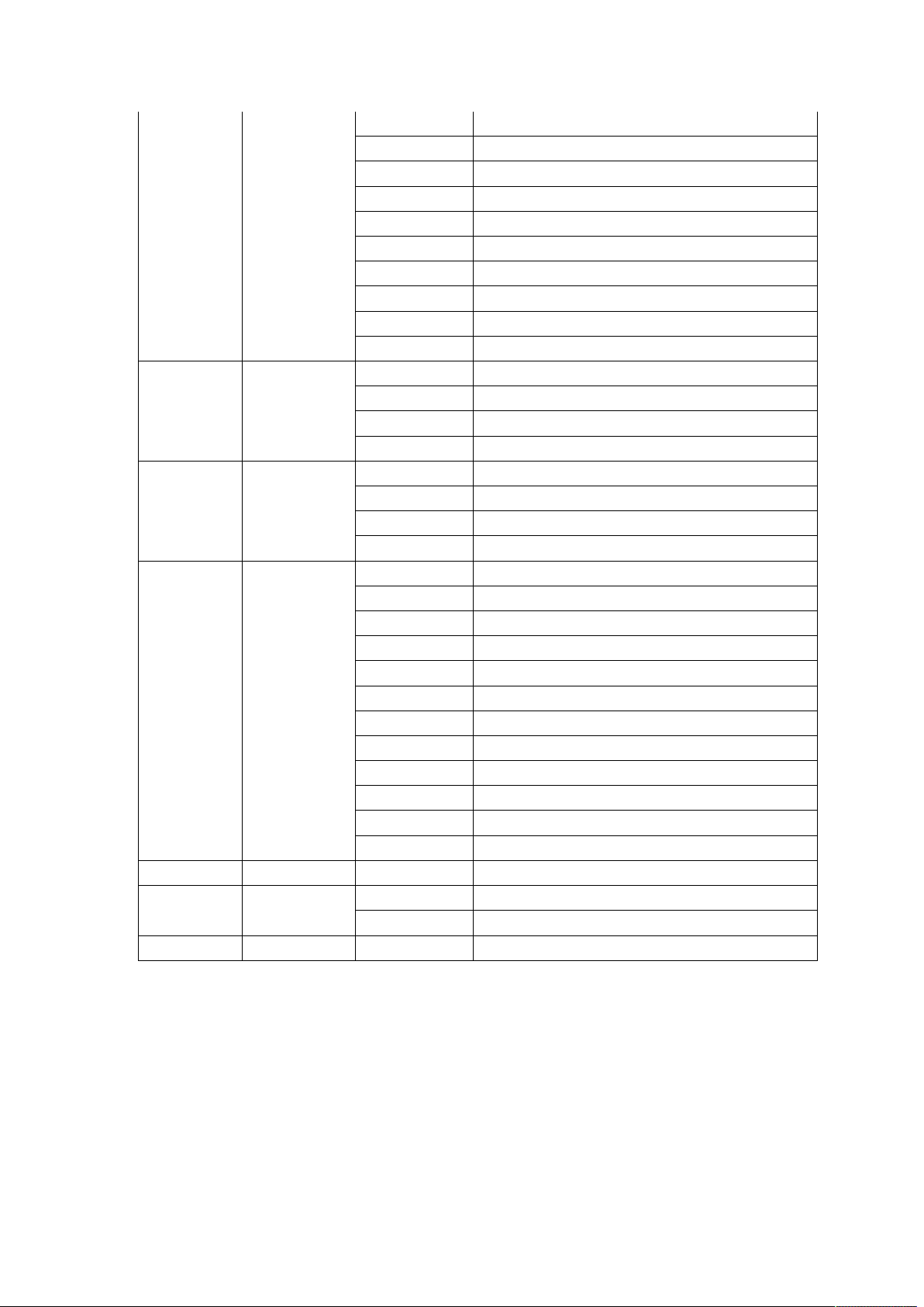
Light support one DMX mode: 18CH:
Table 1 Channel brief
CHANNEL NAME VALUE DEFIF
CH1 PAN 0-255 0-540°
CH2 PAN 16bit 0-255
CH3 TILT 0-255 0-270°
CH4 TILT 16bit 0-255
CH5 XY Speed 0-255 Fast to slow
CH6 Dimmer 0-255 0-100%
0-3 Drak
4-103 Slow strobe to fast strobe
104-107 White
CH7 Strobe
CH8 Frost
CH9 COLOR
108-207 Slow strobe to fast strobe(mode 2)
208-212 White
213-251 Free strobe
252-255 White
0-127 None
128-255 Insert frost
0-4 White
5-9 White + COLOR1
10-14 COLOR1
15-19 COLOR1 + COLOR2
20-24 COLOR2
25-29 COLOR2 + COLOR3
30-34 COLOR3
35-39 COLOR3 + COLOR4
40-44 COLOR4
45-49 COLOR4 + COLOR5
50-54 COLOR5
55-59 COLOR5 + COLOR6
60-64 COLOR6
65-69 COLOR6 + COLOR7
70-74 COLOR7
75-79 COLOR7 + COLOR8
80-84 COLOR8
85-89 COLOR8 + COLOR9
90-94 COLOR9
95-99 COLOR9 + COLOR10
100-104 COLOR10
Page 11
Page 12
CH10 GOBO
CH11 Rainbow
CH12 Prism
105-109 COLOR10 + COLOR11
110-114 COLOR11
115-119 COLOR11 + COLOR12
120-124 COLOR12
125-129 COLOR12 + COLOR13
130-134 COLOR13
135-139 COLOR13 + COLOR14
140-199 Rotate forward (fast to slow)
200-255 Rotate reverse (slow to fast)
0-4 White
5-9 GOBO1
10-14 GOBO2
15-19 GOBO3
20-24 GOBO4
25-29 GOBO5
30-34 GOBO6
35-39 GOBO7
40-44 GOBO8
45-49 GOBO9
50-54 GOBO10
55-59 GOBO11
60-64 GOBO12
65-69 GOBO13
70-125 Rotate forward (fast to slow)
126-130 Stop
131-190 Rotate reverse (slow to fast)
191-195 Shake slow to fast GOBO1
196-200 Shake slow to fast GOBO2
201-205 Shake slow to fast GOBO3
206-210 Shake slow to fast GOBO4
211-215 Shake slow to fast GOBO5
216-220 Shake slow to fast GOBO6
221-225 Shake slow to fast GOBO7
226-230 Shake slow to fast GOBO8
231-235 Shake slow to fast GOBO9
236-240 Shake slow to fast GOBO10
241-245 Shake slow to fast GOBO11
246-250 Shake slow to fast GOBO12
251-255 Shake slow to fast GOBO13
0-127 None
128-255 Rainbow Open
0-30 None
31-50 Prism1
Page 12
Page 13
51-70 Prism2
71-90 Prism3
91-110 Prism4
111-130 Prism5
130-150 Prism6
151-170 Prism7
171-190 Prism8
191-210 Prism9
211-230 Prism10
231-255 Prism11
0-127 0-400 degrees
128-187 Rotate forward (fast to slow)
CH13 Prism1 Rot
188-195 Stop
196-255 Rotate reverse (slow to fast)
0-127 0-400 degrees
128-187 Rotate forward (fast to slow)
CH14 Prism2 Rot
188-195 Stop
196-255 Rotate reverse (slow to fast)
0-30 None
31-50 Macro1
51-70 Macro2
71-90 Macro3
91-110 Macro4
111-130 Macro5
CH15 Macro
130-150 Macro6
151-170 Macro7
171-190 Macro8
191-210 Macro9
211-230 Macro10
231-255 Macro11
CH16 Focus 0-255 From far to near
100-105 Close lamp over 3 sencods
CH17 Lamp
200-205 Open lamp over 3 sencods
CH18 Reset 240-255 Reset over 3 sencods
Page 13
Page 14

14
Page 15

15
Page 16

16
 Loading...