


MicroGuard 534
Operator’s Manual


NOTICE
SkyAzúl makes no warranty of any
kind with regard to this material, including, but not limited to, the
implied warranties of merchantability and/or its fitness for a particular purpose.
SkyAzúl will not be liable for errors contained in this manual or for incidental or consequential
damages in connection with the furnishing, performance, or use of this manual. This document
contains proprietary information, which is protected by copyright, and all rights are reserved.
No part of this document may be photocopied, reproduced, or translated to another language without
the prior written consent of SkyAzúl.
SkyAzúl reserves proprietary rights to all drawings, photos and the data contained therein. The
drawings, photos and data are confidential and cannot be used or reproduced without the written
consent of SkyAzúl. The drawings and/or photos are subject to technical modification without prior
notice.
All information in this document is subject to change without notice.
SkyAzúl, Equipment Solutions www.skyazul.com 301-371-6126
SkyAzúl, Inc.
16 Walnut Street
Middletown, MD 21769
Fax 301-371-0029
info@skyazul.com


MicroGuard 534 Operator’s Manual
TABLE OF CONTENTS
CONSOLE LAYOUT AND DESCRIPTION ............................................................................................ 1
SYSTEM DESCRIPTION ....................................................................................................................... 2
DISPLAY UNIT ...................................................................................................................................... 2
SYSTEM OPERATION .......................................................................................................................... 4
SYSTEM SELF-TEST ............................................................................................................................ 4
SYSTEM BYPASS ................................................................................................................................ 4
CONFIGURATION SELECTION ............................................................................................................ 5
NORMAL WORKING SCREEN EXAMPLES ......................................................................................... 9
SELECTION OF RIGGING/TRAVEL MODE ........................................................................................ 11
CANCEL AUDIBLE ALARM AND RESET FUNCTION LIMITERS ...................................................... 11
OPERATOR SETTABLE ALARMS ..................................................................................................... 11
ANGLE, LENGTH, AND HEIGHT OPERATOR SERRABLE ALARMS ............................................... 12
SWING OPERATOR SETTABLE ALARM ........................................................................................... 13
OPERATOR DEFINED AREA ALARM ................................................................................................ 13
SETTING OPERATOR DEFINED AREA ALARM ................................................................................ 14
SYSTEM FAULT CODES .................................................................................................................... 16
CALIBRATION ..................................................................................................................................... 16
SkyAzúl, Equipment Solutions www.skyazul.com 301-371-6126


1
MicroGuard 534
Operator's Manual
SkyAzúl, Equipment Solutions
www.skyazul.com
1
301-371-6126
32
4
5
17
16
15
14
13
12
36.5’
2_
9.7 X 1000 LBS MAX
0.5
61.0
60.0ft
90.0ft
!! TWO BLOCK !!
12000
6
1
7
1. Bar-Graph
2. Pre-Alarm Indicator
3. Overload Indicator
4. Maximum Rated Capacity Display
5. Actual Load Display
6. Parts-of-Line Display
Figure 1−68
Microguard 534 Rated Capacity Limiter
11 10 9 8
7. Configuration Selection Buttons
8. Cancel Alarm Button
9. Operator Alarms Button
10. Crane Setup Button
11. Display/Select Button
12. Warning Message Area
13. Boom Length Display
14. Brightness Buttons
15. Load Radius Display
16. Boom Angle Display
17. Erected Attachment Display

MicroGuard 534 Rated Capacity
MicroGuard 534
Operator's Manual
SkyAzúl, Equipment Solutions
www.skyazul.com
2
301-371-6126
Limiter
The following describes the function and operation of
the Microguard 534 Rated Capacity Limiter. The system is intended to aid the operator in the efficient operation of the crane by continually monitoring the load
and warning of an approach to an overload or unsafe
condition.
WARNING
Although the system will alert the operator of
an approaching overload or unsafe condition,
it remains the responsibility of the operator to
operate the crane safely at all times.
This system must never be substituted for the
good judgment of the crane operator using safe
operating procedures. The operator is solely
responsible for safe operation of the crane.
!!THIS SYSTEM IS AN OPERATOR’S AID −
NOT A SAFETY DEVICE!!
3
2
1
1. Green Lights − Percentage of Rated Load
231
2. Amber Lights − Approaching Overload
3. Red Lights − Overload
System Description
The system monitors crane functions by means of high
accuracy sensors and continuously compares the load
with a copy of the crane capacity chart which is stored
in the computer memory. If an overload is approached,
the system warns by means of audible and visual
alarms and is configured to cause function limitation.
The MicroGuard 534 Rated Capacity Limiter provides
the operator with a continuous display of:
Rated Capacity
Actual Load
Percentage of Rated Capacity
Radius of the Load
Angle of the Main Boom
Crane Configuration
Length of the Main Boom
An additional feature of the system is the provision of
operator settable alarms. These alarms, when properly set, provide a method of obstacle avoidance. This is
achieved by means of maximum boom angle, maximum load radius, maximum boom head height, left
and right swing, and defined area alarms. These
alarms can be programmed for each job site and set
rapidly for the prevailing site conditions thereby aiding
the operator in safe operation of the crane.
Figure 1−69
Overhead Bar Graph And External Light Bar
(If Equipped)
Display Unit
The following is a description of the control buttons, indicators, and windows on the display unit. Use them
along with Figure 1−68.
1. Bar-Graph
The Bar-Graph is a series of twelve colored lights which
gives a visual indication of how much of the crane’s capacity is being used and the rate at which an overload
is being approached. Each green light represents 10%
of the crane’s rated capacity is being used. Yellow indicates 90−99.9%, and the red lights indicate an overload.
Note: System may be equipped with an overhead
bar graph or an external light bar which operates
similar to the bar graph on the display. Refer to
Figure 1−69.
2. Pre-Alarm indicator
The Pre-Alarm (yellow) Indicator illuminates at a preset value of 90% of Maximum Rated Capacity and provides a visual indication of an approach to an overload.

3. Overload Indicator
MicroGuard 534
Operator's Manual
SkyAzúl, Equipment Solutions
www.skyazul.com
3
301-371-6126
10. Crane Setup Button
The Overload Indicator (red) illuminates at a pre-set
value of 100% of Maximum Rated Capacity and provides a visual indication of Maximum Allowed Load. It
will also illuminate whenever a wire rope limit is exceeded. Function limiters will occur simultaneously for an
Overload, Wire Rope Limit, or a Two Block condition
but function limiters will not occur when exceeding an
operator settable alarm. An audible alarm will sound
and a message will appear in the warning message
area for all 4 conditions.
4. Maximum Rated Capacity Display
The Maximum Rated Capacity is a digital display of the
maximum permitted capacity. It is derived from a copy
of the crane’s capacity chart which is stored in the computer memory and is the reference capacity for any lifting operation. It is dependent on the configuration currently selected, which is shown in the crane setup
screen, and which determines the section of the capacity chart to be used as the rated capacity reference.
5. Actual Load Display
The Actual Load Display is a digital display which
shows total load suspended below the boom or fly
head. It includes the load, any slings, pins, or tackle
used to secure the load and the hook block or ball.
6. Parts-of-Line Display
Parts-of-Line displays the parts of line currently selected for the winch in use.
7. Configuration Selection Buttons
These buttons are used during the crane configuration
selection routine. Refer to Configuration Selection"
found later in this Section of the Operator’s Manual.
8. Cancel Alarm Button
This button is used to silence the audible alarm when
the alarm has occurred as a result of either an Overload, Wire Rope Limit, a Two Block, or an Operator Settable alarm. It is also used to reset the function limit
relay when it is necessary to by-pass function limit
which has occurred as a result of either an Overload,
Wire Rope Limit, or a Two Block alarm.
This button is used to start the configuration selection
routine. Refer to Configuration Selection" found later
in this Section of the Operator’s Manual.
11. Display/Select Button
This button is used to access the Calibration And Diagnostic Screen. Refer to System Fault Codes" and
Calibration" found later in this Section of the Operator’s Manual.
12.Warning Message Area
The Warning Message Area displays text messages of
various alarms which may occur during normal operation of the system. When an alarm occurs, the rectangular area fills in red.
13. Boom Length Display
The Boom Length Display gives a continuous indication of the boom length in feet (m). It is the distance
from the centerline of the boom foot pin to the center
line of the boom head machinery.
14. Brightness Buttons
These buttons are used to adjust the display brightness.
15.Load Radius Display
The Load Radius Display gives a continuous indication
of the radius of the load in feet (m). It is the horizontal
distance from the centerline of rotation to the centerline
of the hook.
16. Boom Angle Display
The Boom Angle Display gives a continuous indication
of the angle of the main boom relative to horizontal.
17. Erected Attachment Display
The Erected Attachment Display gives a continuous
display of the erected attachment with the top number
indicating the actual fly length and the bottom number
indicating the offset angle if applicable.
9. Operator Alarms Button
This button is used to start the operator settable alarms
routines. Refer to Operator Settable Alarms" found
later in this section of the Operator’s Manual.
System Operation
MicroGuard 534
Operator's Manual
SkyAzúl, Equipment Solutions
www.skyazul.com
4
301-371-6126
The following is a list of procedures which are used to
operate the multiple features of the Rated Capacity
Limiter. Use these procedures in conjunction with the
previous display unit control descriptions.
System Self-Test
At start-up the system automatically performs a self test
after which all lamps, audible alarms, and digital displays will be functionally tested and all memory areas
checked for accuracy. If faults in the system are detected during a test, the warning message area will
show the words SYSTEM FAULT. If the words SYSTEM
FAULT occur, press the Display/Select button to display the Calibration And Diagnostic screen. Through
the Calibration And Diagnostic screen, information can
be accessed about the fault condition by means of an
error code. Contact your local distributor for details of
the fault codes.
Note: If the batteries have been disconnected interrupting power to the computer, the start-up time for
on-board computer systems will be longer than
normal.
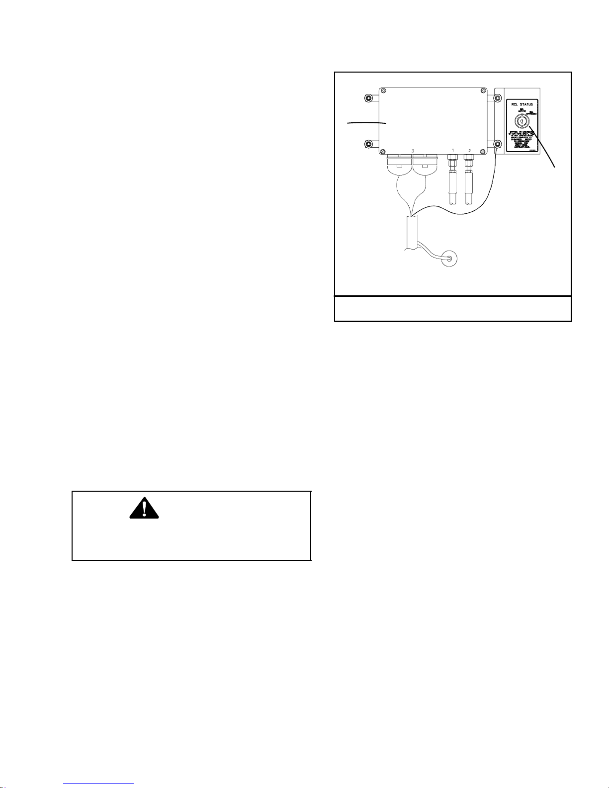
System Bypass
In emergency situations, the Rated Capacity Limiter
computer can be bypassed. The computer is located
on the back of the operator’s cab. Refer to
Figure 1−70. There is a RCL Status keyswitch adjacent to the computer to bypass the system. Move the
key to the Bypass" position to bypass the system. For
emergency use while the system is bypassed, refer to
System Inoperative or Malfunctioning" that follows.
WARNING
The Microguard 534 is not operational when
the computer is bypassed. Bypass the
system in emergency situations only.
System Inoperative Or Malfunctioning
When operational aids are inoperative or malfunctioning, the following recommendations for continued use
of the crane should be followed or the crane should be
shutdown.
1. Steps shall be taken to schedule repairs and recalibration immediately. The operational aids shall be
put back into service as soon as replacement
parts, if required, are available and the repairs and
recalibration can be carried out. Every reasonable
effort must be made to expedite the repairs and recalibration.
1
2
1. RCL Status Keyswitch 2. Computer
Figure 1−70
Rated Capacity Limiter Computer
2. When the rated capacity limiter is inoperative or
malfunctioning, the designated person responsible for supervising the lifting operations shall establish procedures for determining load weights
and shall ascertain that the weight of the load does
not exceed the crane ratings at the radius where
the load is to be handled.
3. When a boom angle or radius indicator is inoperative or malfunctioning, the radius or boom angle
shall be determined by measurement.
4. When the anti-two block warning device is inoperative or malfunctioning, the designated person responsible for supervising the lifting operations
shall establish procedures, such as assigning an
additional signal person, to furnish equivalent
protection. This does not apply when lifting personnel in load line supported baskets. Personnel
shall not be lifted in load line supported baskets
when the anti-two block devices are not functioning properly.
5. When a boom length indicator is inoperative or
malfunctioning, the designated person responsible for supervising the lifting operations shall establish the boom length at which the lift will be
made by actual measurement or markings on the
boom.
6. When a level indicator is inoperative or malfunctioning, other means shall be used to level the
crane.
7. In situations where inconsistency exists, verified
weights, measured radii, boom lengths, and authorized crane capacities must always take precedence over indicator readings.

Configuration Selection
MicroGuard 534
Operator's Manual
SkyAzúl, Equipment Solutions
www.skyazul.com
5
301-371-6126
In the normal operational mode the system is programmed to remember the last configuration selected. Each time
the system is powered up it will automatically default to that configuration. Only when the crane is rigged differently
must a new configuration be selected. Use the following procedure to select the crane configuration.
Note: When selecting configurations allowed on outriggers, all beams must be equally extended; all fully
retracted, intermediate extended, or fully extended.
Depending on how the crane is equipped or which selections have been made, some screens shown may not
appear or may not appear as illustrated. The system cannot be programmed for configurations not allowed
by the capacity charts listed in the Crane Rating Manual.
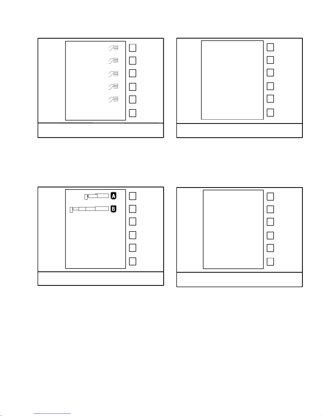
Figure 1−71
Carrier Selection
1. From the normal working screen press the CRANE SETUP button. The normal working screen will change and
graphically display the carrier options. Press the corresponding configuration selection button to select the
desired carrier configuration. If rigging is desired, refer to To Select Rigging/Travel Mode" found later in this
Section of the Operator’s Manual.
WARNING
The Microguard 534 is not operational when in the RIGGING/TRAVEL Mode. Return the Microguard 534
to normal operation before operating the crane.
0
MicroGuard 534
Operator's Manual
SkyAzúl, Equipment Solutions
www.skyazul.com
6
301-371-6126
4 000
8 000
12000
16000
Figure 1−72
Counterweight Selection
2. The carrier selection screen will change and
graphically display the counterweight options.
Press the corresponding configuration selection
button to select the installed counterweight.
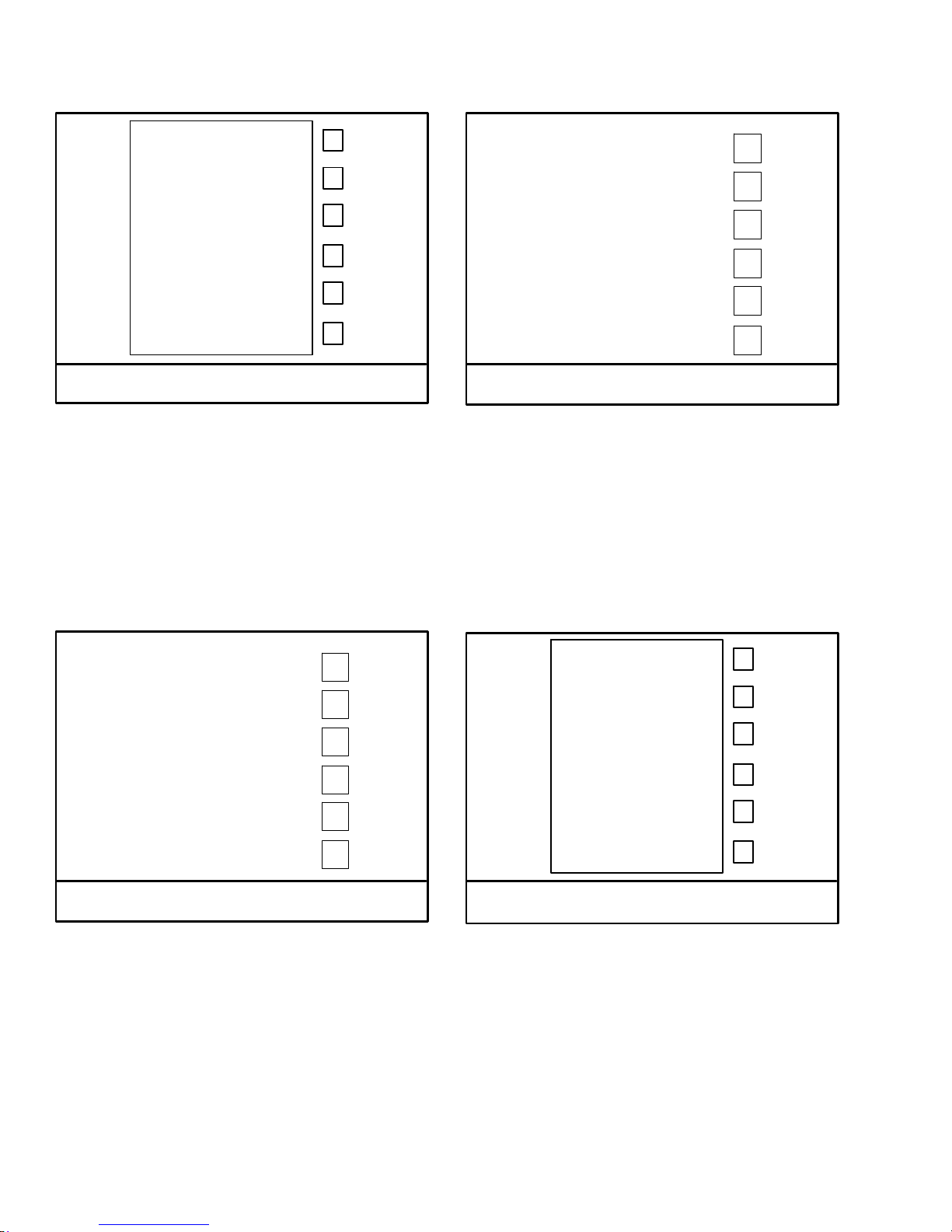
Figure 1−73
Boom Extend Mode Selection
Figure 1−74
Auxiliary Head Selection
4. The boom mode selection screen will change and
graphically display the auxiliary lifting sheave fitted
or not fitted. Press the corresponding configuration selection button to select the acual auxiliary lifting sheave configuration.
36.5’ Fly
61’ Fly
Figure 1−75
Erected Attachment Selection
3. The counterweight selection screen will change
and graphically display the boom mode options.
Press the corresponding configuration selection
button to select the desired boom mode.
Note: Consult the Crane Rating Manual to determine the best boom mode to maximize lift capacity at working radius. Boom mode options
will only be displayed when the boom is fully retracted.
5. If the crane is equipped with a fly, the auxiliary
sheave selection screen will change and graphically display an erected attachment. Press the corresponding configuration selection button to select the installed erected attachment if required.
20
MicroGuard 534
Operator's Manual
SkyAzúl, Equipment Solutions
www.skyazul.com
7
301-371-6126
40
Figure 1−76
Erected Attachment Offset Selection
6. If an offset fly was previously selected, the erected
attachment selection screen will change and
graphically display the available offset angles.
Press the corresponding configuration selection
button to select the installed offset angle if required.
Figure 1−78
Front Winch Lifting Point Selection
8. If the crane is equipped with a front winch, the rear
winch lifting point screen will change and graphically display the front winch lifting point. Press the corresponding configuration selection button to select
the actual front winch lifting point. Or press the corresponding configuration selection button to select
the front winch not in use.
24.5’
36.5’
61’
Figure 1−77
Rear Winch Lifting Point Selection
7. The erected attachment or erected attachment offset selection screen will change and graphically
display the rear winch lifting point. Press the corresponding configuration selection button to select
the actual rear winch lifting point. Or press the corresponding configuration selection button to select the rear winch not in use.
Figure 1−79
Stowed Attachment Selection
9. If the crane is equipped with a fly and was not selected as an erected attachment, the winch lifting
point screen will change and graphically display
the stowed attachment. Press the corresponding
configuration selection button to select the actual
stowed attachment if required.

Figure 1−80
MicroGuard 534
Operator's Manual
SkyAzúl, Equipment Solutions
www.skyazul.com
8
301-371-6126
Rear Winch Parts Of Line Selection
Figure 1−81
Front Winch Parts Of Line Selection
10. The crane setup screen will change to the normal
working screen and graphically display the crane
configuration as previously selected. Press the
corresponding configuration selection button to
select the actual parts of line for the rear winch.
11. If the crane is equipped with a front winch and it
was selected, press the corresponding configuration selection button to select the front winch.
Press the corresponding configuration selection
button to select the actual parts of line for the front
winch.
Note: From the normal working screen, after
crane setup has been established, only two
selection buttons are active; the winch select
button and the parts of line button.
To change winches, push the winch select button to toggle between winches. The winch lifting points cannot be changed without going
through the crane setup routine.
The parts of line can be changed for the selected winch by pressing the parts of line button
to scroll through the available options for that
winch.
Refer to Figure 1−82 and Figure 1−83 for examples of some normal working screens.

4
MicroGuard 534
Operator's Manual
SkyAzúl, Equipment Solutions
www.skyazul.com
9
301-371-6126
8
7
6
9
2
5
1
3
In this example the crane is setup on fully extended outriggers (1), boom mode B (2), 12,000 lb
counterweight (3), 36.5’ fly base erected at 2 degree offset (4), fly tip stowed (5), the rear winch
available with the main boom head and the front winch selected (6), with the winch rope reeved
over the fly base (7), with one part of line (8), and an operator settable alarm enabled (9).
7
6
5
2
4
3
1
In this example the crane is setup on intermediate extended outriggers (1), boom mode B (2), 12,000 lb counterweight (3) 61’ fly
stowed (4), the front winch available with the auxiliary head and
the rear winch selected (5), with the winch rope reeved over the
main boom head (6) with three parts of line (7).
Figure 1−82
Normal Working Screen Examples

6
MicroGuard 534
Operator's Manual
SkyAzúl, Equipment Solutions
www.skyazul.com
10
301-371-6126
5
4
2
7
3
1
In this example the crane is setup for stationary on tires (1), boom mode
B (2), 12,000 lb of counterweight (3), front winch not in use and the rear
winch selected (4), winch rope reeved over the main boom (5), with
three parts of line (6), and the 61’ fly stowed (7).
7
4
6
2
5
1
3
In this example the crane is setup on fully retracted outriggers (1),
boom mode B (2), 12,000 lb of counterweight (3), winch rope
reeved over the main boom (4), 61’ fly stowed (5), rear winch not
in use and the front winch selected (6), with three parts of line (7).
Figure 1−83
Normal Working Screen Examples
Cancel Audible Alarm And Reset Function Limiters
MicroGuard 534
Operator's Manual
SkyAzúl, Equipment Solutions
www.skyazul.com
11
301-371-6126
The CANCEL ALARM button is used to cancel the
audible alarm when the alarm has occurred as a result
of either an Overload, a Two Block alarm, or an Operator settable alarm. The audible alarm may be canceled
by pressing and releasing the CANCEL ALARM button.
The audible alarm remains canceled until the condition
which caused the alarm has been removed. For example, if the audible alarm was canceled because of an
overload condition, it will remain canceled until the
overload condition is removed. However, if a different
alarm, e.g. two block condition, was to occur when the
audible alarm was still canceled for an earlier overload
condition, the new alarm condition would cause the audible alarm to be re-started.
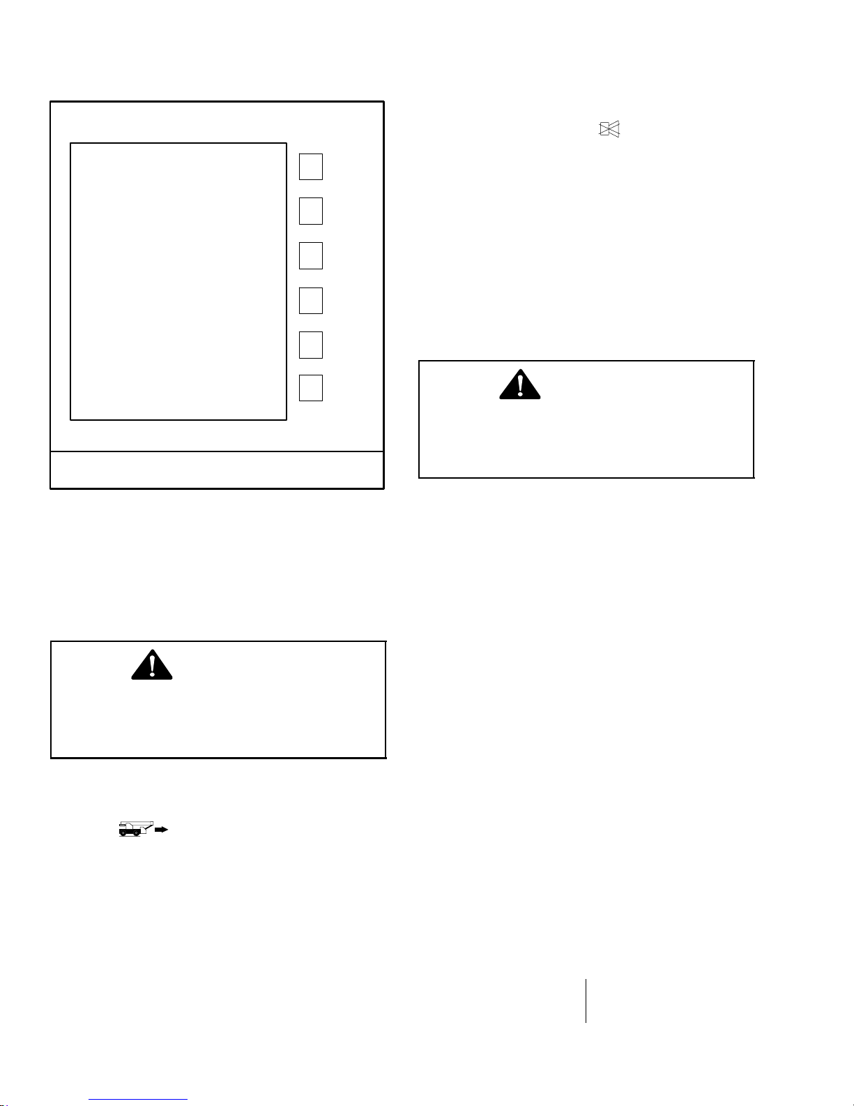
Figure 1−84
Rigging/Travel Mode Screen
To Select Rigging/Travel Mode
The CRANE SETUP push button is also used to select
RIGGING/TRAVEL MODE. This mode is used to facilitate rigging and travel of the crane by inhibiting function limiters and the audible alarm while selected. To
resume crane operation, select proper outrigger or tire
configuration per the proper procedure.
WARNING
The Microguard 534 is not operational when in
the RIGGING/TRAVEL Mode. Return the Microguard 534 to normal operation before operating the crane.
1. From the normal working screen press the CRANE
SETUP button. The crane setup screen will
change and graphically display the carrier options.
2. Select for stationary rigging or when traveling the crane. Refer to Figure 1−84.
Note: Boom must be fully retracted to enter
travel mode.
WARNING
Once the function limiters have been
by-passed, the crane is no longer protected
against the condition that initially caused the
function limiters to occur.
Note: The CANCEL ALARM feature is a temporary
function. The audible alarm or function limit is automatically reset when the condition which caused
the alarm is no longer present.
The CANCEL ALARM is also used to reset the function
limiters when it is necessary to by-pass the function limiters which has occurred as a result of either an overload, a two block alarm, or a rope limit. Function limiters are reset by first canceling the audible alarm (as described above) and then pressing and holding the
CANCEL ALARM button for about 3 seconds, after
which the function limiters will be reset to allow normal
operation. However, should another different alarm
condition occur when the function limiters had previously been over-ridden, then the newly occurring
alarm condition would cause the function limiters to activate again.
Operator Settable Alarms
Some alarms occur automatically as a result of limitations imposed by the capacity chart. The operator has
control over additional alarms which can be set to operate within the normal chart limitations and which are, in
addition to, those already set by the chart.
Operator settable alarms will be stored in the computer
memory, even if the crane is shutdown, until they are
cleared. Refer to Figure 1−85.
Alarms available for operator use are:
Minimum Boom Angle Maximum Boom Length
Maximum Boom Angle Left and Right Swing
Maximum Tip Height Operator Defined Area

EXIT
MicroGuard 534
Operator's Manual
SkyAzúl, Equipment Solutions
www.skyazul.com
12
301-371-6126
SETTABLE ALARMS
BOOM LIMITS
SWING LIMITS
AREA LIMITS
Figure 1−85
Boom Limit Alarms
WARNING
The operator settable alarms are a warning
device. All functions remain operational when
entering the operator defined bad area. For
safe operation, adequate distance must be
maintained to allow for operator reaction time
to avoid entering the bad area. It is the
responsibility of the operator to set points
which ensure that the crane’s boom,
attachment, load, rigging, etc. maintains a
safe working distance and complies with local
safety regulations.
Angle, Length, And Height Operator Settable Alarms
1. From the normal working screen press OPERATOR ALARM button to access the Settable
Alarms screen.
2. Press the corresponding button for Boom Limits
.
WARNING
Avoid positioning the boom, attachment, load,
rigging, etc. into the bad area when setting the
alarm values.
When selecting the alarm values, ensure that
the load will maintain a safe distance from the
obstacle.
EXIT
4. Press the corresponding selection button to set the
desired alarm value as defined below. Press the
button again to turn alarm off.
5. When all alarm values are set, press the EXIT button to return to the alarm screen. At the Settable
Alarm screen, press the EXIT button again to return
to the normal working screen.
6. Test the alarm, with no load, to ensure the alarm
points have been properly set. When approaching
the alarm set point, the audible will sound intermittently and a warning message will appear in the
warning message area. When exceeding the
alarm set point, the audible alarm will sound continuously and a warning message will appear in
warning message area.
Note: An alarm icon will appear on the normal working screen to alert the operator that an
operator alarm has been set.
75.0
HEIGHTLENGTH ANGLE
75.0 75.0 60.0
75.0
60.0
30.0
Maximum Boom Length
Maximum Tip Height
Maximum Boom Angle
Minimum Boom Angle
3. Position the boom in the desired position depending upon the alarm to be set. The numerical value
displayed will be the current position of the boom.
WARNING
If crane or obstacle is moved or if a different
size load is lifted, the alarm(s) must be reset.

265.0
MicroGuard 534
Operator's Manual
SkyAzúl, Equipment Solutions
www.skyazul.com
13
301-371-6126
SET
SETTABLE ALARMS
BOOM LIMITS
SWING LIMITS
AREA LIMITS
Figure 1−86
Swing Alarm
Swing Operator Settable Alarm
To have an alarm whenever the left swing and right
swing exceed pre-determined alarm points, use the following procedure:
1. From the normal working screen press OPERATOR ALARM button to access the Settable
Alarms screen.
2. Press the corresponding button for Swing Limits
.
3. Swing the boom to the left alarm point .
4. Press the corresponding button for Left Swing
to enter the left alarm point. The displayed value
will be the left alarm setting.
5. Swing the boom to the right alarm point.
6. Press the corresponding button for Right Swing
to enter the right alarm point. The displayed
value will be the right alarm setting.
7. Press the EXIT button to return to the settable
alarm screen. Press the EXIT button on the settable alarms screen to return to the normal working
screen.
8. Test the alarm, with no load, to ensure the alarm
points have been properly set. When approaching
the set alarm point, the audible alarm will sound intermittently and Swing Alarm" will appear in the
warning message area. The audible alarm will activate whenever the swing exceeds the alarm points
and Swing Alarm" will appear in warning message
area.
EXIT
SWING ANGLE
95.0
EXIT
95.0
SET
Operator Defined Area Alarm
The operator defined area alarm, when set, will define
an imaginary vertical plane between two set points to
optimize the working area. When approaching the
plane, the audible alarm will sound intermittently, and
the message Bad Working Area" will appear in the
warning message area. When passing the plane, the
audible alarm will sound continuously and the message Bad Working Area" will appear on the warning
message area. Use the following procedure,
Figure 1−87, and Figure 1−88 to set the operator defined area alarm.
WARNING
The operator defined area alarm is a warning
device. All functions remain operational when
entering the operator defined bad area. For
safe operation, adequate distance must be
maintained to allow for operator reaction time
to avoid entering the bad area. It is the
responsibility of the operator to set points
which ensure that the crane’s boom,
attachment, load, rigging, etc. maintains a
safe working distance and complies with local
safety regulations.
Note: Both the left and right swing alarms must
be set for the system to determine the operator
set working area.
Note: An alarm icon will appear on the normal working screen to alert the operator that an
operator alarm has been set.

EXIT
MicroGuard 534
Operator's Manual
SkyAzúl, Equipment Solutions
www.skyazul.com
14
301-371-6126
SETTABLE ALARMS
BOOM LIMITS
SWING LIMITS
AREA LIMITS
Figure 1−87
Operator Defined Area Alarm
Setting Operator Defined Area Alarm
1. From the normal working screen press OPERATOR ALARM button to access the Settable
Alarms screen.
2. Disable any previously set left and right swing
alarms if required.
Note: The left and right swing alarms must be
cleared prior to setting the defined area alarm.
3. Press the corresponding button for Area Limit .
WARNING
Avoid positioning the boom, attachment, load,
rigging, etc. into the bad area when setting the
left or right alarm points.
When selecting the left and right alarm points,
ensure that the load will maintain a safe
distance from the obstacle. Also ensure that
the two points are set so that the tailswing of
the crane will not enter the bad area.
4. Position the boom, attachment, load, rigging, etc.
to the right alarm point and press the corresponding button to enter the right alarm point. The
displayed value will be the right alarm setting.
5. Position the boom, attachment, load, rigging, etc.
to the left alarm point and press the corresponding
EXIT
SWING ANGLE
97.2
button to enter the left alarm point. The displayed value will be the left alarm setting.
Note: For best results, the two points should be
separated by a minimum of 10 ft (3m) or 30 de-
grees.
6. When both alarm points are set, press the EXIT
button to return to the settable alarms screen.
Press the EXIT button on the settable alarms to return to the normal working screen.
7. Test the alarm, with no load, to ensure the alarm
points have been properly set. When approaching
the plane, the audible alarm will sound intermittently and the message Bad Working Area" will appear on the warning message area. When passing
the plane, the audible alarm will sound continuously and the message Bad Working Area" will appear on the warning message area.
WARNING
If crane or obstacle is moved or if a different
size load is lifted, the area alarm must be
reset.
Note: An alarm icon will appear on the normal working screen to alert the operator that an
operator alarm has been set.

IlIIIIIIlnary
MicroGuard 534
Operator's Manual
SkyAzúl, Equipment Solutions
www.skyazul.com
15
301-371-6126
Vertlclll Plane
RlahtAiann
Polnt
Figure 1−88
Operator Defined Area Alarm
Working Area

Figure 1−89
MicroGuard 534
Operator's Manual
SkyAzúl, Equipment Solutions
www.skyazul.com
16
301-371-6126
Calibration And Diagnostic Screen
CALIBRATION AND DIAGNOSTICS
A00 B0 C00 D00
ERROR CODES
ENTER CALIBRATION
Message Data Count
System Fault Codes
If faults in the system are detected during a test, the
warning message area will show the words SYSTEM
FAULT. If the words SYSTEM FAULT occur, press the
Display/Select button to display the Calibration And
Diagnostic screen. On the Calibration And Diagnostic
screen, press the Error Code button to display error
codes in the box at the top of the screen. This information can then be used to assist the service technician in
determining the fault. Contact your distributor for assistance with the fault codes.
Calibration
If the system requires calibration, contact you distributor for assistance. Calibration must be done by a qualified technician. Press the Display/Select button to display the Calibration And Diagnostic screen. On the
Calibration And Diagnostic screen, press the Enter
Calibration button. The calibration screen will be displayed and prompt a calibration key sequence to begin
the calibration routine.


SkyAzúl, Equipment Solutions www.skyazul.com 301-371-6126
www.skyazul.com
SkyAzúl, Inc.
16 Walnut Street
Middletown, MD 21769
Phone 301-371-6126
Fax 301-371-0029
info@skyazul.com
 Loading...