


SIGALARM
MODEL 210
ANTI TWO-BLOCK
EI10
EI20
Troubleshooting Manual


Troubleshooting Manual
NOTICE
SkyAzúl makes no warranty of any kind with regard to this material, including, but not limited to,
the implied warranties of merchantability and/or its fitness for a particular purpose.
SkyAzúl will not be liable for errors contained in this manual or for incidental or consequential
damages in connection with the furnishing, performance, or use of this manual. This document
contains proprietary information, which is protected by copyright, and all rights are reserved.
No part of this document may be photocopied, reproduced, or translated to another language
without the prior written consent of SkyAzúl.
SkyAzúl reserves proprietary rights to all drawings, photos and the data contained therein. The
drawings, photos and data are confidential and cannot be used or reproduced without the
written consent of Hirschmann. The drawings and/or photos are subject to technical
modification without prior notice.
All information in this document is subject to change without notice.
MANUAL REVISIONS
REV DATE NAME DESCRIPTION
- 05/17/11 SC A2B/EI10/EI20 Troubleshooting Manual (SkyAzúl) Rev -
SkyAzúl, Inc.
16 Walnut Street
Middletown, MD 21769
Fax 301-371-0029
info@skyazul.com
SkyAzúl, Equipment Solutions www.skyazul.com 301-371-6126

Troubleshooting Manual
SkyAzúl, Equipment Solutions www.skyazul.com 301-371-6126

Troubleshooting Manual
A2B
SkyAzúl, Equipment Solutions
www.skyazul.com
301-371-6126
1 General Flowchart -
A2B
1.1
This section explains
procedures are easy
general
Sections 2 through
flowchart
below
4.
how
to
follow
to
handle a problem that may arise with the PAT
and are given in flowcharts on the
which
will guide you
to
one
of
the more detailed flowcharts shown in
following
START
Whafs Wrong?
Anti-
Two-Block. The
pages. Start with the
Lever Lockout No Function Length Cable
Activated Anti-Two-Block Problem
Go
10
Seclion 2
Go
10
Section 3
Go
10
Section 4

Troubleshooting Manual
A2B
SkyAzúl, Equipment Solutions
www.skyazul.com
301-371-6126
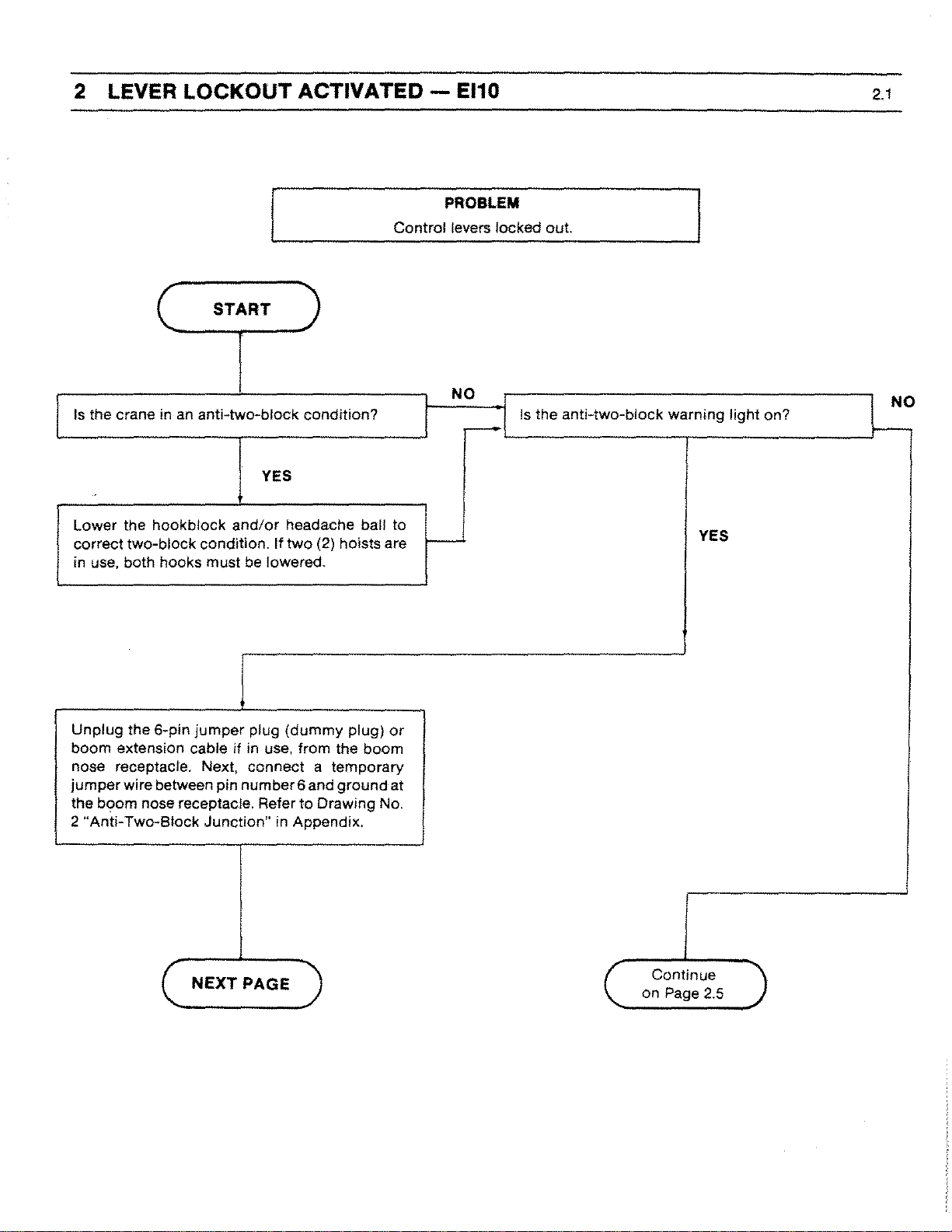
2 LEVER LOCKOUT ACTIVATED -
Control levers locked out.
A2B
PROBLEM
2.1
(
Is
the crane in
Lower the
correct two-block condition.
in use, both hooks must
Unplug the 6-pin
boom extension cable
nose receptacle. Next, connect a temporary
jumper
the boom nose receptacle. Refer to Drawing No.
"Anti-
2
hookblock
wire between pin number6 and ground at
Two-Block Junction" in Appendix.
START
an
anti-two-block condition?
YES
and/or
jumper
if
headache ball
If
two (2) hoists are
be
lowered.
plug (dummy plug)
in use, from the boom
to
or
t--
NO
.--
Is
the anti-two-block warning light on?
YES
NO
f--
NEXT PAGE
(
(
Continue
on Page 2.5

Troubleshooting Manual
A2B
SkyAzúl, Equipment Solutions
www.skyazul.com
301-371-6126
2 LEVER LOCKOUT ACTIVATED -
PREVIOUS PAGE
A2B
2.2
Does the anti-twa-block warning light switch off?
YES
Move the temporary jumper wire from pin #6
pin
#1
at the boom nose receptacle. Leave the
other end on ground. The boom nose anti-two-
must
be
block switch
Does the anti-twa-block warning
pulled down
off?
by
its weight.
light
to
remain
YES
Operating
plug. Check wiring in jumper plug and boom
nose receptacle.
Operating on Jib - Defect in wiring
attachment (jib, boom nose, etc.). Check wiring
of switches.
on
Main Boom - Problem in
jumper
or
switches of
NO
NO
Remove cover
jumper
connect between
Refer to
Appendix.
Main boom nose anti-twa-block switch or wiring
is defective
boom nose receptacle.
of
cable reel. Move the temporary
wire from boom nose receptacle and
slip
ring terminals #17 and
Drawing No. 1
or
incorrectly
"Slip Ring Unit" in
connected in switch
#18.
or
-
NEXT PAGE
Troubleshooting Manual
A2B
SkyAzúl, Equipment Solutions
www.skyazul.com
301-371-6126
2 LEVER LOCKOUT ACTIVATED -
A2B
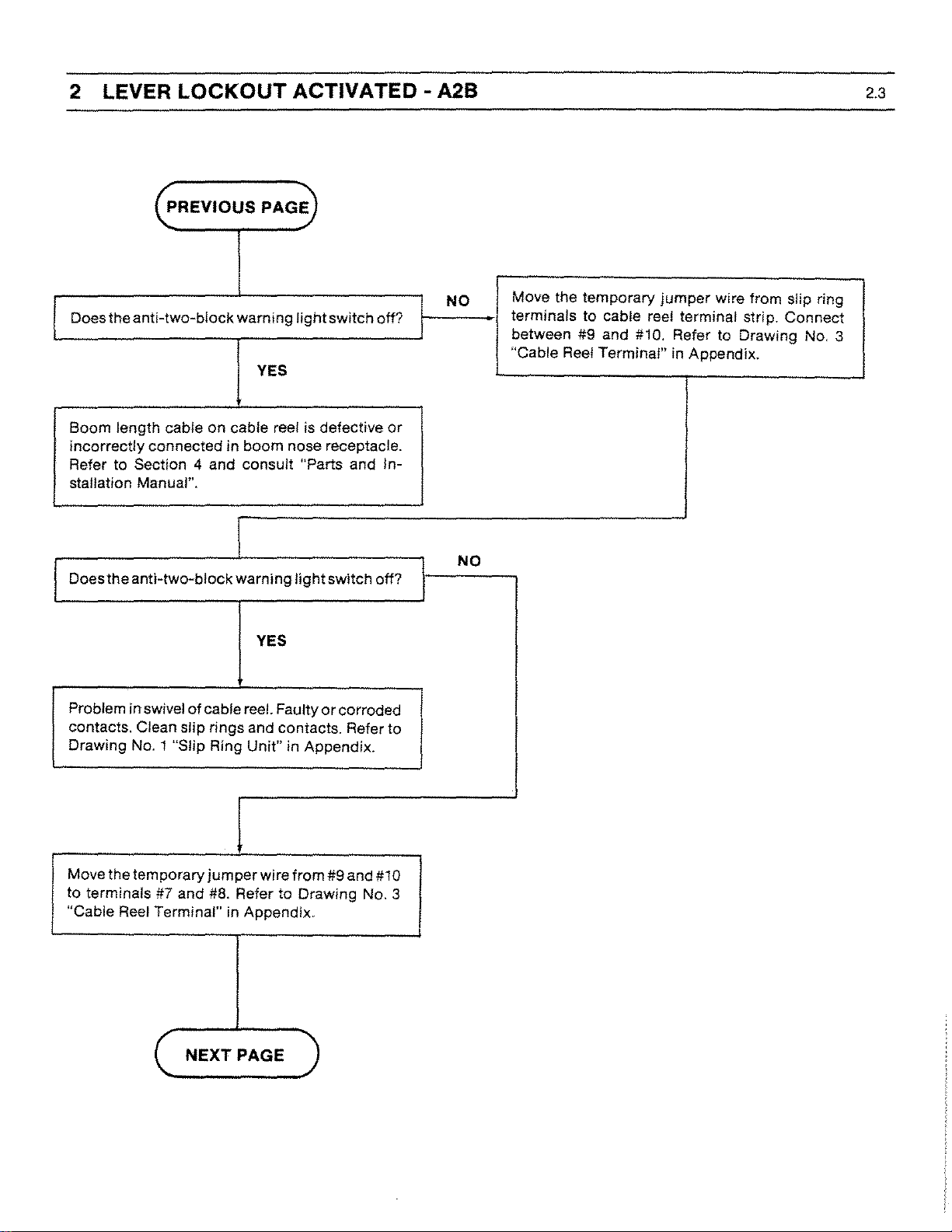
2.3
~REVIOUS
Does the anti-two-block warning
PAGE
light
switch off?
YES
Boom length cable
incorrectly connected in boom nose receptacle.
Refer to Section 4 and consult "Parts and Installation Manual".
Does the anti-two-block warning
on
cable reel is defective
light
switch off?
or
YES
NO
NO
Move the temporary
terminals to cable reel terminal strip. Connect
between #9 and #10. Refer to Drawing
"Cable Reel Terminal" in Appendix.
jumper
wire from slip ring
NO.3
Problem in swivel
contacts. Clean slip rings and contacts. Refer to
Drawing No.1 "Slip Ring Unit" in Appendix.
Move the temporary
to terminals #7 and
"Cable Reel Terminal" in Appendix.
of
cable reel. Faulty
jumper
#8.
NEXT
wire from #9 and #10
Refer to Drawing
PAGE
or
corroded
No.3

Troubleshooting Manual
A2B
SkyAzúl, Equipment Solutions
www.skyazul.com
301-371-6126
2 LEVER LOCKOUT ACTIVATED -
PREVIOUS PAGE
A2B
2.4
Does theanti-two-block warning light switch off?
YES
Faulty terminal strip between #7 and #9
#10 - check continuity on terminal strip. Replace
to
terminal strip. Refer
Reel Terminal" in Appendix.
Does the anti-two-block warning light switch off?
Drawing
No.3
or#8
"Cable
and
YES
NO
NO
Remove front panel
in cab. Move temporary
and connect between terminal #3 and #4. Refer
Drawing
to
Diagram in Appendix.
Relay in console defective.
NO.4
on
"Anti-
Anti-
Two-Block console
jumper
wire to console
Two-Block
Wiring
I
I
Faulty wiring between cable reel and console.
Check wiring. Referto Drawing
Block Wiring Diagram" in Appendix.
No.4
"Anti-
Two-

Troubleshooting Manual
A2B
SkyAzúl, Equipment Solutions
www.skyazul.com
301-371-6126
2 LEVER LOCKOUT ACTIVATED -
Continued
from Page
C
2.1
A2B
2.5
Check the fuse in the face
console. Refer
Block Console" in Appendix. Is fuse defective?
to
of
Drawing
the Anti-Two-Block
No.5
"Anti-Two-
NO
Is lever lockout system functioning when keyswitch is in bypass position?
NO
No power to Anti-Two-Block console
of
lockout system
1.
Check power supply
Block console at terminal
#2
terminal
2.
Check
hydraulic
= ground.
wire
or
= Crane Voltage (e.g.
UB
crane is not functioning.
of
crane to Anti-Two-
#1
connections
air system
for
the lever lockout.
= +UB and at
to
24V112V).
or
lever
solenoid and
YES
YES
Replace 10amp. fuse and examine wiring to lever
lockout
Relay in
place relay.
solenoids.
Anti-
Two-Block
console defective. Re-
END

Troubleshooting Manual
A2B
SkyAzúl, Equipment Solutions
www.skyazul.com
301-371-6126
3
NO
FUNCTION
START
ANTI-
Anti-Twa-Block
TWO-BLOCK - A2B
PROBLEM
System does
two-block condition.
not
operate when crane is in
3.1
Does the
when crane is two-blocked?
Unplug
boom extension cable,
receptacle. Refer
Block
Does the anti-two-blook warning light switch on?
anti-twa-block
the 6-pin
Junction"
in Appendix.
jumper
if
to
Drawing
warning light switch on
plug (dummy plug)
in use,
from
No.2
boom
"Anti-Two-
or
nose
YES
Remove
from
1.
at boom nose receptacle.
2.
block switch by operating switch by hand. Switch
should be closed when pulled down, open when
released.
dummy
boom
Connect
Check
continuity
plug
or
unplug extension jumper
nose receptacle.
an
ohmmeter
between Pin #1 and
of
the
boom
#6
nose anti-two-
YES
NO
Anti-twa-block
trol lever lockout system is
1.
Bypass key
2. Bypass keyswitch may be faulty.
3.
Lever lockout solenoid valve may
connected
Refer to Drawing
sole" in Appendix.
Remove cover on cable reel. Disconnect length
cable core wire from slip ring terminal #17.
warning
is
to
incorrect
turned
No.5
light
does light but con-
not
functioning.
to
bypass position.
be
faulty or
power
supply.
"Anti-Twa-Block Con-
Does switch operate correctly?
Operating on Main
plug. Check wiring in
nose receptacle.
Operating on
attachment (jib, boom nose, etc.). Check wiring
of
switches.
Jib
- Defect in wiring
I
1
Boom
jumper
YES
- Problem in
plug and boom
or
jumper
switches
of
NO
Anti-two
wired. Wiring
receptacle. Refer to Drawing
Block Wiring Diagram" in Appendix and consuit
"Parts and Installation" manual.
block switch is faulty
may be faulty to boom nose
(
NEXT
PAGE
or
No.4
incorrectly
"Anti-Twc-

Troubleshooting Manual
A2B
SkyAzúl, Equipment Solutions
www.skyazul.com
301-371-6126
3
NO
FUNCTION
PREVIOUS PAGE
ANTI-
TWO-BLOCK - A2B
3.2
Does the anti-two-block warning light switch on?
1
YES
Faulty length cable on reel
nections at boom nose receptacle.
DoestheantHwo-block
or
Incorrect con-
warning lightswitch on?
YES
Short circuit in internal wiring of cable reei
defective cable between cable reel and console.
to
Refer
Diagram" in Appendix.
Drawing
No.4
"Anti-Two
Block Wiring
or
NO
NO
I
~
Disconnect the #7 wire from cable reel terminal
strip.
Remove front panel
Disconnect wire #7 from console terminal #4.
on
Anti-Twa-Block console.
DoestheantHwo-block
Faulty wiring between console and cable
Check for short
between wire
Drawing
in Appendix.
No.4
circuit
'7
and crane ground. Refer to
"Anti-Twa-Block Wiring Diagram"
warning lightswitch on?
YES
reel.
and damaged cable
NO
Anti-two-block warning lamp may be burned
out
Turn buzzer switch on.
check lamp. If buzzer does not sound, check
relay. Refer to Drawing NO.5 "Anti-Two-Block
Console" in Appendix.
If
buzzer sounds,

Troubleshooting Manual
A2B
SkyAzúl, Equipment Solutions
www.skyazul.com
301-371-6126
4 BROKEN LENGTH CABLE -
Damaged
A2B
PROBLEM
or
broken length cable.
4.1
STEP
1
2
3
4
5
6
7
8
ACTION
Cut
old cable at cable drum.
Open cable reel cover and disconnect wiring from terminal block. Pull 7 -conductor cable out
of strain relief.
Remove cable reel from mounting brackets.
Remove damaged length cable, which is mounted
18.
and
Refer
to
Drawing No. 1 in Appendix.
Turn the cable reel and open the strain relief attached to the axle in the center
length cable out of the cable reel.
Disconnect damaged length cable from Anti-Two-Block switch receptacle at the boom nose.
Pull new length cable through the hole, pipe and strain relief and push
drum. Tighten strain relief to ensure sealing.
Dismantle length cable near slip ring and reconnect shield to terminal No. 18 and center to No.
Refer to Drawing No. 1 in Appendix.
to
the slip rings in the cable reel, from Terminal 17
of
the drum. Pull existing
it
through the axle of the reeling
H.
9
10
11
Remount cable reel to the boom. Turn reeling drum clockwise to get rest
Set preload on cable reel by turning the drum counter-clockwise 5 to 8 turns.
Reconnect new cable to Terminal
boom nose. Refer to Drawing
of
new cable
No.1
(center) and ground terminal (shield)
No.2
in Appendix and consult "Parts and Installation" manual.
of
onto
the drum.
receptacle at the

Troubleshooting Manual
A2B
SkyAzúl, Equipment Solutions
www.skyazul.com
301-371-6126
APPENDIX
Drawing 4 - ANTI-TWO-BLOCK WIRING DIAGRAM
6 PIN
r----
{'~f.l!
'~'
lj , ...
~
'
3'
\
i'
5:;1
,
~s>'
f~~~~~~H~~
6 PIN
JUMPER
PLUG
NOTES'
[!:>
OUTER
RELIEF
[[>
INNER
AS
tr:>
INNER
G:>
OUTER
AS
~
I
1
i
ANTI-
TWO-BLOCK
SWITCH
SHIELD
CONNECTOR
SHIELD
SHOWN
SHIELD
SHIELD
SHOWN
GROUNDeD
INSULATED
CUT
~ePTACtE
:----------------------------------
~
~
,
ttl!
=-------.;
:\~'
"-
L
_______________________________________
AT
AND
OFF
INSULATED
AND
AND
1.
STRAIN
CONNECTEO
TAPED
CONNECTED
,"'"
ltt£
CABLE
REEL
TO CONSOlE
-'
r"-l
~
1 i
i
1:
10 PIN
PLUG
j
/
ELECTRICAL DIAGRAM ~ BOOM
NOTES
II>
[1:> INSULA
[!:>
B:>
NOTE: This diagram may
particular crane model
for
I~--------~-~------
I i
109871$543
I
3
i
i
L,
_______
~~Z,~~
~~~~~C;~~UNOEO
TED
SH!ELD AND CONNECTED
INNER
oureR
differ
WIRE SOLDERED TO INNER
SHf€lD
CUT
SHIELD CUT OFF AND TAPED
from the actual wiring of the system supplied, Consult the Parts & Installation Manual
a detailed wiring diagram.
OFF
AND
AT
STRAIN
AS
SHOWN
TAPED
ELECTRICAL DIAGRAM ~ LOWER
10
PIN;
PLUG,
_
TO CABLE REEL
---
---1
,
I
for
your

Troubleshooting Manual
A2B
SkyAzúl, Equipment Solutions
www.skyazul.com
301-371-6126
Drawing 5 - ANTI-TWO-BLOCK CONSOLE
APPENDIX
ALARM
BY-PASS
HORN

Troubleshooting Manual
A2B
SkyAzúl, Equipment Solutions
www.skyazul.com
301-371-6126
Drawing 6 - EI10 CONSOLE
APPENDIX
PAT
1--2
I
I 3
J 1 1
---
EI
10
1 I
-,
,-
='.
I-'
LI
ALARM

Troubleshooting Manual
A2B
SkyAzúl, Equipment Solutions
www.skyazul.com
301-371-6126
APPENDIX
Drawing 7 -
TERMINAL
ANTI-
TWO-BLOCK CABLE REEL
BLOCK
SLIP RING BOOY
MOUNTING
PLATE

Troubleshooting Manual
EI10
SkyAzúl, Equipment Solutions
www.skyazul.com
301-371-6126
1 General Flowchart - EI10
1.1
This section explains
are easy
to
follow
how
to
handle a problem that may arise with the PAT
and are given in flowcharts on the following pages. Start with the general
flowchart below which will guide you to one
through
Lever Lockout
6.
Activated
I
No Function
Anti-Two-Block
What's
EI-1
O.
The procedures
of
the more detailed flowcharts shown in Sections 2
START
Wrong?
Length Cable
Problem
No Display
Go
to
Section 2 Go
to
Section 3
Wrong Angle
Displayed
Go to Section 6
Go
to
Section 4
I I
Go
to
Section 5
I

Troubleshooting Manual
EI10
SkyAzúl, Equipment Solutions
www.skyazul.com
301-371-6126
3 NO FUNCTION ANTI-TWO-BLOCK - EI10
PROBLEM
Anti-Twa-Block
System does
two-block condition.
not
3.1
operate when crane is in
(
Does the
when crane
Unplug
boom extension cable, if in use, from boom nose
receptacle. Refer to Drawing
Block
Does the anti-twa-block warning light switch on?
anti-twa-block
is
the 6-pin
Junction"
START
warning light switch on
two-blocked?
NO
jumper
in Appendix.
plug
(dummy
No.2
"Anti-
plug)
Two-
or
1
Remove
from boom nose receptacle.
1.
at boom nose receptacle.
2.
block switch by operating switch by hand. Switch
should be closed when pulled down, opens when
released.
dummy
Connect an
Check
continuity
plug
or
ohmmeter
of
the
unplug extension jumper
between Pin
boom nose anti-two
#1
and #6
I YES
I
I
NO
i
I
I
I
I
I
I
Anti-twa-block
trol lever lockout system
warning
light
does
light
is
not functioning.
I
1.
Bypass key is turned to bypass position.
2.
Bypass keyswitch may be faulty.
3.
Lever
lockout
connected to incorrect power supply.
Refer
Appendix.
I
I
cable core wire from slip ring terminal #17.
-I
to
Remove cover on cable reel. Disconnect length
solenoid valve may be faulty
Drawing
NO.6
I
I
I
"Ella
Console"
I
but Con-
or
in
I
I
!
I
I
I
,
I
I
I
I
Does switch operate correctly?
Operating on Main
plug. Check
nose receptacle.
Operating on Jib - Defect in wiring
attachment (jib,
of
switches.
wiring
boom
I
I
y
E S
Boom
- Problem in jumper
in
jumper
nose, etc.). Check wiring
plug and boom
or
switches
of
NO
Anti-two
wired. Wiring may be faulty
receptacle. Refer to Drawing No.
Diagram"
I nstallation" manual.
block
switch is faulty
in Appendix and consult "Parts and
NEXT PAGE
or
incorrectly
to
boom nose
10"El10Wiring
Troubleshooting Manual
EI10
SkyAzúl, Equipment Solutions
www.skyazul.com
301-371-6126
2 LEVER LOCKOUT ACTIVATED - EI10
PROBLEM
Control levers locked out.
START
2.1
Is the crane in
Lower the hookblock
correct two-block condition. If
in use. both hooks must be lowered.
Unplug
boom extension cable if in use, from the boom
nose receptacle. Next, connect a temporary
jumper
the
2
the 6-pin
wire between pin number 6 and ground at
boom
"Anti-
Two-Slock Junction" in Appendix.
an
anti-twa-block condition?
YES
and/or
jumper
nose receptacle. Refer
headache ball to
two
plug (dummy plug)
(2) hoists are
to
Drawing No.
or
t--
NO
.--
Is
the anti-two-block warning light on?
YES
NO
t--
NEXT
C
PAGE
Continue
on Page
2.5

Troubleshooting Manual
EI10
SkyAzúl, Equipment Solutions
www.skyazul.com
301-371-6126
2
LEVER
c;.REVIOUS PAGE
LOCKOUT ACTIVATED - EI10
2.2
Does the anti-twa-block warning light switch off?
YES
Move the temporary
# 1 at the
pin
other end on ground. The boom nose anti-twoblock
switch must be pulled down by its weight.
Does the anti-two-block warning
Operating on Main Boom -
plug. Check wiring in
nose receptacle.
Operating on Jib - Defect in wiring
attachment (jib, boom nose, etc.). Check wiring
of
switches.
boom
jumper
nose receptacle. Leave the
off?
wire from pin #6 to
light remain
YES
Problem in
jumper
plug and boom
or
switches
jumper
of
NO
NO
Remove cover
jumper
connect
Refer to Drawing
Appendix.
Main boom nose anti-twa-block switch
is
defective
boom nose receptacle.
of
wire
from
between
or
incorrectly
cable reel. Move the temporary
boom
slip
nose receptacle and
ring terminals#17 and#1S.
No. 1 "Slip Ring
connected in switch
Unit"
or
wiring
in
or
NEXT PAGE

Troubleshooting Manual
EI10
SkyAzúl, Equipment Solutions
www.skyazul.com
301-371-6126
2 LEVER LOCKOUT ACTIVATED - EI10
PREVIOUS PAGE
2.3
Does the anti-two-block warning lightswitch off?
YES
Boom length cable on cable reel is defective
incorrectly connected in boom nose receptacle.
to
Refer
stallation Manual".
Does the anti-two-block warning light switch off?
Section 4 and consult "Parts and In-
or
YES
Problem in swivel
contacts. Clean slip rings and contacts. Refer to
Drawing No.1 "Slip Ring Unit" in Appendix.
of
cable reel. Faulty
or
corroded
NO
I
NO
Move the temporary jumper wire from slip ring
terminals to cable reel terminal strip. Connect
#9
between
"Cable Reel Terminal" in Appendix.
and #10. Refer to Drawing
NO.3
Move the temporary jumper wire from
#7
to terminals
"Cable Reel Terminal" in Appendix.
and
NEXT PAGE
#9
#8.
Refer to Drawing NO.3
and #10

Troubleshooting Manual
EI10
SkyAzúl, Equipment Solutions
www.skyazul.com
301-371-6126
2
LEVER
LOCKOUT ACTIVATED - EI10
2.4
~REVIOUS
Does the anti-two-block warning light switch off?
PAGE
YES
Faulty terminal strip between #7 and
#10 - check continuity on terminal strip. Replace
terminal strip. Refer to Drawing
Reel
Terminal" in Appendix.
Does the anti-two-block warning lightswitch off?
#9
NO.3
or
#8
"Cable
and
NO
NO
Remove front panel on
Move temporary
connect between terminal #9 and #2. Refer to
Drawing
Appendix.
Electronic component defective on internal board.
No. 10
jumper
"Ell0
Ell0
console
wire to console and
Wiring
in
Diagram"
cab.
in
YES
Faulty wiring between console and cable reel.
to
Check wiring. Refer
Wiring Diagram" in Appendix.
Drawing No. 10
"Ell0

Troubleshooting Manual
EI10
SkyAzúl, Equipment Solutions
www.skyazul.com
301-371-6126
2 LEVER LOCKOUT ACTIVATED - EI10
Continued
(
from Page
2.1
2.5
Check the fuse in the attached override box
the
Ell0
console.
Is
lever lockout system functioning when key-
switch
console at t",rminal
ground.
2.
hydraulic
is
in bypass position?
No power to Antilockout system
1.
Check power supply
Check
wire
or
Is
fuse burned out?
Two-Slock
of
crane is
#1
connections
air system
NO
NO
console
not
functioning.
of
crane to the
= +US and at terminal
to
for
the lever lockout.
or
solenoid and
lever
Ell0
#2
Us = Crane Voltage (e.g. 24V/12V).
of
=
i
I
YES
YES
Replace
lockout solenoids.
10
amp. fuse and examine wiring
Internal defect in electronics.
to
lever
END

Troubleshooting Manual
EI10
SkyAzúl, Equipment Solutions
www.skyazul.com
301-371-6126
3
NO
FUNCTION ANTI-TWO-BLOCK - EI10
PREVIOUS PAGE
3.2
Does
the
anti-twa-block
warning light switch on?
YES
Faulty length cable on reel or incorrect connections
Does the anti-twa-block warning
at
boom
nose receptacle.
light
switch on?
YES
Short
circuit
defective cable between cable reel and console.
Refer
to
in Appendix.
in Internal wiring
Drawing
No.
10
of
"Ell0
Wiring Diagram"
cable reel
or
NO
NO
Disconnect the #7 wire from cable reel terminal
I
strip.
Remove front panel on El10console. Disconnect
wire #7 from console terminal #9.
Does the anti-twa-block warning light switch on?
Faulty wiring between console and cable reel.
Check
between
Drawing
Appendix.
for
short
wire
No.
*7
10
YES
l
circuit and damaged cable
and crane ground. Refer to
"Ell0
Wiring
Diagram"
in
NO
Anti-twa-block warning lamp may be burned
out. Turn buzzer switch on.
check lamp. If buzzer does
relay. Refer to Drawing NO.6
Appendix.
If
buzzer sounds.
not
sound, check
"E11O
Console" in
I
I
I
I
I
I

Troubleshooting Manual
EI10
SkyAzúl, Equipment Solutions
www.skyazul.com
301-371-6126
4 BROKEN LENGTH CABLE - EI10
Damaged
PROBLEM
or
broken length cable.
4.1
STEP
1
2
3
4
5
6
7
8
ACTION
Cut
old cable at cable drum.
Open cable reel cover and disconnect wiring from terminal block. Pull 7-conductor cable out
of
strain relief.
Remove cable reel from mounting brackets.
Remove damaged length cable, which
and
18.
Refer to Drawing No. 1 in Appendix.
Turn the cable reel and open the strain relief attached to the axle in the center
length cable out
Disconnect damaged length cable from Anti-Two-Block switch
Pull new length cable through the hole, pipe and strain relief and push it through the axle
drum. Tighten strain relief to ensure sealing.
Dismantle length cable near slip ring and reconnect shield to terminal No.
Refer to Drawing No. 1 in Appendix.
of
the cable reel.
is
mounted
to
the slip rings in the cable reel, from Terminal
of
the drum. Pull existing
receptacle
at
the boom nose.
of
18
and center to No.
the reeling
17
17.
9
10
11
Remount cable reel to the boom. Turn reeling drum clockwise to get rest
Set preload on cable reel by turning the drum counter-clockwise 5 to 8 turns.
Reconnect new cable to Terminal
boom nose. Refer to Drawing
of
new cable onto the drum.
No.1
(center) and ground terminal (shield)
No.2
in Appendix and consult "Parts and Installation" manual.
of
receptacle at the

Troubleshooting Manual
EI10
SkyAzúl, Equipment Solutions
www.skyazul.com
301-371-6126
5
NO
DISPLAY - EI10
5.1
PROBLEM
No display.
START
Check
2 (gnd) in console. Refer
Wiring Diagram" in Appendix.
for
voltage across Terminal 1
to
Drawing No. 10"E110
I YES
Check board fuse to see if
Drawing No.
Appendix.
Failure
card
of
(AID
12
"E110
Console Terminals" in
I
NO
electronic component. Change LCD
converter)
andlor
(=
+ UB) and
it
is blown. Refer to
replace main board.
NO
YES
Faulty power supply. Check crane electric.
I
Replace fuse.
I

Troubleshooting Manual
EI10
SkyAzúl, Equipment Solutions
www.skyazul.com
301-371-6126
6 WRONG ANGLE DISPLAY - EI10
Incorrect angle display.
START
6.1
PROBLEM
Open
terminal#5
Voltage should be
"Cable Reef Terminal" in Appendix.
cable
(+5V)
reel
and
and#6
5V.
check
(gnd) on terminal strip.
Refer
voltage
to
Drawing
across
NO.3
NO
Check voltage on socket 5 (+5V) and 6 (gnd) in
10-pin receptacle located at base boom section.
Voltage should be
5V.
I
Check voltage on pins 5 and 6 in 10-pin plug
located at base boom section. Voltage should be
5V.
YES
YES
YES
I
NEXT
C
Fault is located in cable from 10-pin receptacle
cable reel.
Fault
is
located in connection
receptacle.
PAGE
of
)
10-pin plug and
to
Check voltage across terminal
(gnd) in console. Voltage should be
Drawing No.3 "Cable
Defective electronic component. Replace main
board and reset system referring to Operator's
Handbook.
NO
10
(+5V) and
5V.
Reel
Terminal" in Appendix.
Refer
12
to
YES
Fault
is
located in cable from console to 10-pin
connector.

Troubleshooting Manual
EI10
SkyAzúl, Equipment Solutions
www.skyazul.com
301-371-6126
6 WRONG ANGLE DISPLAY - EI10
PREVIOUS PAGE
Check voltages at cable reel between terminal#4
(signal) and #6 (gnd). Voltage should be stable
and in the range of 1.8V to 3.1V (0"
3.l0V;
"Cable
45°
= 2.45V). Refer to Drawing No. 3
Reel
Terminal" in Appendix.
= 1.80V; 90" =
6.2
NO
Change angle transducer.
Open 10-pin receptacle located at boom base
section and check voltage between Pin 4 and Pin
6.
Voltage should
Open plug and check between Pin 4 (signal) and
Pin 6 (gnd) for same voltage
reconnected.
Open console and check
terminal#ll
tween
to Drawing No.
Appendix.
Defective electronic component. Replace main
board and reset system referring to Operator's
Handbook.
be
same
as
above.
YES
as
above with plug
YES
for
same voltage be-
(signal) and#12 (gnd). Refer
12
"Ell0
Console Terminals" in
NO
NO
NO
Fault is located in cable from 10-pin receptacle to
cable reel.
Faulty 10-pin connector.
·1
O-pin
Defective cable from console to 1
•
Check wiring. Refer to Drawing No.
Wiring Diagram" in Appendix.
connector.
10
I
"Ell0

Troubleshooting Manual
EI10
SkyAzúl, Equipment Solutions
www.skyazul.com
301-371-6126
Drawing 6 - EI10 CONSOLE
APPENDIX
PAT
1--2
I
I 3
J 1 1
---
EI
1 I
-,
10
,-
='.
ALARM
I-'
LI

Troubleshooting Manual
EI10
SkyAzúl, Equipment Solutions
www.skyazul.com
301-371-6126
Drawing 8 - EI10 CABLE REEL
APPENDIX
ANGLE TRANSDUCER
TERMINAL
BLOCK
i
~
~
SLIP RING BODY

Troubleshooting Manual
EI10
SkyAzúl, Equipment Solutions
www.skyazul.com
301-371-6126
NOTE: This diagram may differ from the actual wiring of the system supplied. Consult the Parts & Instaliation Manual for your
particular crane model
for
TERM!NALS
+5V
""gn,'-
gnd 12
a detailed
ON
PCB
10
~
11
wiring
diagram.
··1····
4,
5 I
:
61
<i9P
..
:::0
'::...Lrt.
......)
~
, 4 I
tR±
7 4
~
6.!
KT200 WG203
,-I
"I
HOIST
WEIGHT
ANGLE
LIMIT
TRANSDUCER
SWITCH (A2B)
c
J.
o
-
m
:::;:
o
!l
:xl
Z
Ii)
c
;;
Ii)
:xl
~
»
"0
"0
m
Z
C
><
ALARM
RELAY
gnd
r2"
+Us
n=b
4-
,..-r
'7
>==
~
...JL
U MAX
co
40V
!MAX'"
1A
Ell0
ANGLE INDICATOR
• JUMPER IF
A28
!S
NOT
2
1
3
4
5
CONNECTED
1
T
-:
2
1
,I,
3
4
5
I<D
24V
(12V)
POWER
St
JPPI Y
BATTERY
'"
Signa! 0"'"' 1,BV
45"
'"
9O"=3.1V
I
(::
2.45V
~

Troubleshooting Manual
EI10
SkyAzúl, Equipment Solutions
www.skyazul.com
301-371-6126
Drawing 12 - EI10 CONSOLE TERMINALS
APPENDIX
BATTERY
®
12V
24V
e
r---F-
0
90
1
a
~~
~
0
0
;=;
-~
~
-
::
\'!~
r
L
..,
....J
12V10.315A
24VfO.315A
,).
--¢
P1
r 1
L J
Drawing 13 - EI20 CONSOLE TERMINALS
I
BATTERY
LWG
12V/0.5A
m_
1r----J,.---1--:-2--1
I(±)
12V
J:
fI''Il
I
.-
el
DC
f--
DC
>--1--:5:---1
DC
>--f--_6---;
1
MIN
MAX
0
0
~~~~-I-'\":-
1
3
4
:
10
11
12
15
--,
,
!
,
,
,
,
,
,
I
i
___
P1
P2
,
:r.l
P3 (P4j*
,~~
,~~
9~0
'" = 45
-cp
0
.."..
1"---'1--:-'
-=c--:n:::"t~P1
-I
_l.drl
~
""Not Installed

Troubleshooting Manual
EI20
SkyAzúl, Equipment Solutions
www.skyazul.com
301-371-6126
1 General Flowchart - EI20
1.1
This section explains
how
to handle a problem that may arise with the PAT EI-20. The procedures
are easy to follow and are given in flowcharts on the following pages. Start with the general
flowchart below which will guide you to one of the more detailed flowcharts shown in Sections 2
through
7.
START
Lever Lockout
Activated
I
No Function
Anti-Two-Slock
What's
Wrong?
I
Length Cable
Problem
No Display
I
Go
to Section 2
I
Go
to Section 3
Wrong Angle
Displayed
Go
to Section 6
Go
to Section 4
Wrong Length
Displayed
Go
to Section 7
I
Go
to Section 5
I

Troubleshooting Manual
EI20
SkyAzúl, Equipment Solutions
www.skyazul.com
301-371-6126
2 LEVER LOCKOUT ACTIVATED - EI20
PROBLEM
Control levers locked out.
NOTE: The ON-OFF switch on the console
or
must be turned to either the left
or
on position
out.
control levers will
the right
be
locked
2.1
(
Is
the crane in an anti-two-block condition?
Lower the hook block
correct two-block condition.
in use, both hooks must
Unplug the 6-pin
boom extension cable
nose receptacle. Next, connect a temporary
jumper wire between pin
the boom nose receptacle. Refer
2 "Anti-Two-Block Junction" in Appendix.
START
and/or
jumper
if
YES
headache ball to
If
two
(2)
hoists are
be
lowered.
plug (dummy plug)
in use, from the boom
number6and
ground at
to
Drawing No.
or
I--
NO
r-
Is
the anti-two-block warning light on?
YES
NO
f--
NEXT
PAGE
Continue
on Page
2.5

Troubleshooting Manual
EI20
SkyAzúl, Equipment Solutions
www.skyazul.com
301-371-6126
2
LEVER
LOCKOUT ACTIVATED - EI20 2.3
~REVIOUS
Does the anti-two-block warning light switch off?
Boom length cable
incorrectly connected in boom nose receptacle,
Refer to Section 4 and consult "Parts and Installation Manual".
Does the anti-two-block warning lightswitch off?
on
PAGE
YES
cable reel
YES
is
defective
or
NO
NO
Move the temporary
terminals to cable reel terminal strip, Connect
between #9 and
"Cable Reel Terminal" in Appendix.
jumper
#10.
wire from slip ring
Refer to Drawing No, 3
Problem in swivel of cable reel. Faulty or corroded
contacts, Clean slip rings and contacts. Refer to
No.1
Drawing
Move the temporary jumper wire from
to terminals
"Cable Reel Terminal" in Appendix,
"Slip Ring Unit" in Appendix.
#9
#7
and #8, Refer to Drawing No, 3
(
NEXT
PAGE
and
#10

Troubleshooting Manual
EI20
SkyAzúl, Equipment Solutions
www.skyazul.com
301-371-6126
2
LEVER
LOCKOUT ACTIVATED - EI20
22
~REVIOUS
Does the anti-two-block warning light switch off?
PAGE
YES
Move the temporary jumper wire from pin #6 to
pin # 1 at the boom nose receptacle, Leave the
other end on ground, The boom nose anti-two-
must
be
block switch
Does the anti-two-block warning
pulled down by its
off?
weight
light remain
YES
NO
NO
Remove cover
jumper wire from boom nose receptacle and
connect between slip ring terminals#17 and #18,
Refer to Drawing No, 1 "Slip Ring
Appendix,
Main boom nose anti-two-block switch
is
defective
boom nose receptacle,
of
cable reel. Move the temporary
or
or
incorrectly connected in switch
Unit" in
wiring
or
Operating on Main Boom - Problem in jumper
plug, Check wiring in jumper plug and boom
nose receptacle,
Operating
attachment (jib, boom nose, etc,), Check wiring
of switches,
on
Jib - Defect in wiring
NEXT
PAGE
or
switches of

Troubleshooting Manual
EI20
SkyAzúl, Equipment Solutions
www.skyazul.com
301-371-6126
2 LEVER LOCKOUT ACTIVATED - EI20
2.4
~REVIOUS
Does the anti-twa-block warning light switch off?
PAGE
YES
Faulty terminal strip between #7 and #9
#10 - check continuity on terminal strip. Replace
terminal strip. Refer to Drawing
Reel Terminal" in Appendix.
Does the anti-twa-block warning light switch off?
NO.3
or
#8 and
"Cable
NO
NO
Remove front panel on EI20 console in cab.
Move temporary
connect between terminal #16 and #2. Refer to
Drawing
Appendix.
Electronic component defective on internal board.
No.
jumper
11
"E120
wire to console and
Wiring
Diagram"
in
YES
Faulty wiring between console and cable reel.
11
Check wiring. Refer to Drawing No.
Wiring Diagram" in Appendix.
"E120

Troubleshooting Manual
EI20
SkyAzúl, Equipment Solutions
www.skyazul.com
301-371-6126
2
LEVER
LOCKOUT ACTIVATED - EI20 2.5
Continued
from Page
2.1
Check the fuse in the attached override box
the EI20 console.
Is
fuse burned out?
NO
Is lever lockout system functioning when key-
switch
is
in bypass position?
NO
No power to Anti-Two-Block console
of
lockout system
1.
Check power supply of crane to the EI20
console at terminal
ground.
2.
Check wire
hydraulic
or
= Crane Voltage (e.g. 24V/12V).
UB
crane is not functioning.
#1
= +UB and
connections
air
system
for
the lever lockout.
atterminal
to
or
solenoid
lever
#2 =
and
of
YES
YES
Replace 10amp. fuse and examine wiring to lever
lockout solenoids.
Internal defect in electronics.
END

Troubleshooting Manual
EI20
SkyAzúl, Equipment Solutions
www.skyazul.com
301-371-6126
3 NO FUNCTION ANTI-TWO-BLOCK - EI20
PROBLEM
Anti-
Two-Block
START
System does not operate when crane is in
two-block condition.
3.1
Does the anti-two-block warning light switch on
when crane is two-blocked?
NO
i
I
Unplug
boom
receptacle. Refer to Drawing
Block
Does the anti-two-block warn ing light switch on?
Remove
from boom nose receptacle.
1.
at boom nose receptacle.
2.
block switch by operating switch
should be closed when pulled down. opens when
released.
the 6-pin
extension cable.
Junction"
dummy
Connect
Check
an
continuity
jumper
if
in Appendix.
plug
or
unplug extension jumper
ohmmeter
of
the boom nose anti-two
plug
(dummy
in use, from
No.2
between Pin #1 and #6
by
plug)
boom
nose
"Anti-Two-
hand. Switch
or
YES
Anti-two-block
trol lever lockout system
warning light does light but con-
is
not functioning.
~
1.
Bypass key
2.
Bypass keyswitch may be faulty.
3.
Lever lockout solenoid valve may be faulty or
connected to incorrect power supply.
Refer to Drawing
Appendix.
I
Remove cover on cable reel. Disconnect length
cable core wire from slip ring terminal
is
turned to bypass position.
No.
14
"E120
Console" in
#17.
!
Does switch operate correctly?
I
Operating
plug. Check wiring in jumper plug and boom
nose receptacle.
Operating onJib - Defect in wiring
attachment (jib. boom nose. etc.). Check wiring
of
switches.
on
Main Boom - Problem in
I
1 YES
jumper
or
switches of
NO
,
I
Anti-two
wired. Wiring
receptacle. Refer
Diagram" in
Installation" manual.
block switch is faulty
may be faulty to boom nose
to
Drawing No.
Appendix
NEXT
and consult "Parts and
PAGE
or
11
incorrectly
"E120
Wiring

Troubleshooting Manual
EI20
SkyAzúl, Equipment Solutions
www.skyazul.com
301-371-6126
3
NO
FUNCTION ANTI-TWO-BLOCK -
EI20
3.2
~REVIOUS
Does the anti-twa-block warning
PAGE
light
j YES
Faulty length cable on reel
nections at boom nose receptacle.
Does the anti-twa-block warning
or
lightswitch
!YES
switch on?
incorrect con-
on?
NO
NO
Disconnect
strip.
Remove
Disconnect wire #7 from console terminal #16.
the
#7
wire from cable reel terminal
front
panel on Anti-Twa-Block console.
Short circuit in internal wiring
defective cable between cable reel and console.
Refer to Drawing No.
in Appendix.
Does the anti-twa-block warning light switch on?
11
"E120
of
cable reel
Wiring Diagram"
or
i
I YES
I
Faulty wiring between console and cable reel.
for
short
Check
between wire
Drawing
Appendix.
No.
circuit
*7
and crane ground. Refer to
11
"E120
and damaged cable
Wiring
Diagram"
in
I
NO
I
Anti-twa-block
out. Turn buzzer switch on. If buzzer sounds.
check lamp. If buzzer does not sound, check
relay. Reter to Drawing No.
Appendix.
warning lamp may
14
"E120
be
burned
Console" in

Troubleshooting Manual
EI20
SkyAzúl, Equipment Solutions
www.skyazul.com
301-371-6126
4 BROKEN LENGTH CABLE - EI20
Damaged
PROBLEM
or
broken length cable.
4.1
STEP
1
2
3
4
5
6
7
8
ACTION
Cut
old cable at cable drum.
Open cable reel
of
strain relief.
Remove cable reel from mounting brackets.
Remove damaged length cable, which is mounted
18.
and
Refer to Drawing No. 1 in Appendix.
Turn the cable reel and open the strain relief attached
length cable out of the cable reel.
Disconnect damaged length cable from Anti-Two-Block switch receptacle at the boom nose.
Pull new length cable through the hole, pipe and strain relief and push
drum. Tighten strain relief to ensure sealing.
Dismantle length cable near slip ring and reconnect shield to terminal No.
Refer
to
Drawing No. 1 in Appendix.
cover and disconnect wiring from terminal block. Pull 7-conductor cable out
to
the slip rings in the cable reel, from Terminal 17
to
the axle in the center
ofthe
drum. Pull existing
it
through the axle
18
and center to No.
of
the reeling
17.
9
10
11
12
Remount cable reel
Set preload on cable reel by turning the drum counter-clockwise 5 to 8 turns.
Reconnect new cable to Terminal No.1 (center) and ground terminal (shield)
boom nose. Refer to Drawing
Reset length potentiometer in length angle transducer (screw is located in center of white gear); with
boom fully retracted, turn potentiometer carefully counter-clockwise until
Anti-Two-Block switch. Recheck length and angle display.
Refer to Drawing No. 9 in Appendix.
to
the boom. Turn reeling drum clockwise to get rest
No.2
in Appendix and consult "Parts and Installation"
of
new cable onto the drum.
of
receptacle at the
manua1.
it
stops. Check function
of

Troubleshooting Manual
EI20
SkyAzúl, Equipment Solutions
www.skyazul.com
301-371-6126
5
NO
DISPLAY - EI-20
5.1
PROBLEM
No display.
13
START
to
Drawing No.
I
YES
"E120
Console Terminals"
I
NO
and/or
replace main board.
(=
+ US) and
11
"E120
in
(
Check
2 (gnd) in console. Refer
Wiring Diagram" in Appendix.
Check board fuse to see if it is blown. Refer to
Drawing No.
Appendix.
Failure
card
for
voltage across Terminal 1
of
electronic component. Change LCD
(AID converter)
NO
YES
Faulty power supply. Check crane electric.
I
Replace fuse.
I

Troubleshooting Manual
EI20
SkyAzúl, Equipment Solutions
www.skyazul.com
301-371-6126
6 WRONG ANGLE DISPLAY - EI20
Incorrect angle display.
6.1
PROBLEM
(
Open
terminal #5 (+4.1V) and #6 (gnd) on terminal
strip. Voltage should be5V. Referto Drawing No.
3 "Cable
cable
Reel
START
reel
and
check
Terminal" in Appendix.
voltage
across
NO
Check voltage on socket 5 (+4.1V) and 6 (gnd) in
10-pin receptacle located at base boom section.
Voltage should be
5V.
YES
YES
( NEXT
Fault is located in cable from 10-pin receptacle to
cable reel.
PAGE)
Check voltage on pins 5
10-pin plug located at base boom section. Voltage
should
Check voltage across terminal
4.1V) in console. Voltage shOuld be
Drawing No.3 "Cable
Defective electronic component. Replace main
board and reset system referring to Operator's
Handbook.
be
5V.
Reel
(+
4.1V) and 6 (gnd) in
NO
10
(gnd) and
5V.
Refer to
Terminal"
in
Appendix.
NO
12
(+
YES
YES
Fault
is
located in connection
receptacle.
Fault
is
located in cable from console to 10-pin
connector.
of
10-pin plug and
•

Troubleshooting Manual
EI20
SkyAzúl, Equipment Solutions
www.skyazul.com
301-371-6126
6 WRONG ANGLE DISPLAY - EI20
6.2
~REVIOUS
Check voltages at cable reel between terminal#4
(signal) and #6 (gnd). Voltage should be stable
and in
the
range
of
O.OOV
1.0;
45'
= 0.5V). Refer
Reel Terminal" in Appendix,
PAGE
to
1.0V
(0'
= 0.0; 90° =
to
Drawing No, 3 "Cable
YES
Open 10-pin receptacle located at boom base
section and check voltage between Pin 4 and Pin
6. Voltage should be same
as
above.
YES
Open plug and check between Pin 4 (signal) and
for
Pin 6 (gnd)
reconnected.
same voltage as above with plug
NO
NO Problem
cable reel.
NO
I
Change angle transducer.
is
in cable from 10-pin receptacle to
Faulty 10-pin connector.
I
YES
Open console and check
tween
strip. Refer to Drawing No.
Terminals" in Appendix.
#11
(signal) and #10 (gnd) at terminal
I
YES
for
same voltage be-
13
"E120
Console
~
Defective electronic component. Replace main
board and reset system referring to Operator's
Handbook.
NO
Defective cable from console to 1 O-pin connector.
Check wiring. Refer to Drawing No.
•
Wiring Diagram" in Appendix.
11
"E120

Troubleshooting Manual
EI20
SkyAzúl, Equipment Solutions
www.skyazul.com
301-371-6126
7 WRONG LENGTH DISPLAY - EI20 7.1
PROBLEM
Incorrect length display.
(
Open cable reel and check potentiometer to see
if
it
is
turning with reel and is in zero position
when
counterclockwise). Refer to Drawing NO.9 "Cable
Reel" in Appendix.
Check voltage across cable reel terminal #2
(signal) and
boom
Check voltage across cable reel terminal
(gnd) and #3 (+5V). Voltage should measure
Refer to Drawing NO.3 "Cable Reel Terminal" in
Appendix.
#1
range
Drawing NO.3 "Cable
of
O.8V
START
is
fully
retracted
(gnd). Voltage should be in the
to
5.0V and stable. Refer to
Reel
Terminal" in Appendix.
(turned
fully
#1
5V.
Setto
NO
NO
zero and readjust
meter
to
Does length display work correctly?
~I
NO
Replace and reset length potentiometer. Refer to
Section
4.
or
rectify fault.
END
Continued on Page
replace length potentio-
YES
7.3.
I
Check
boom base section, across terminal #2 and #1.
Voltage should be same
for
voltage at 1 O-pin receptacle. located at
NEXT
(
YES
as
above.
YES
PAGE
NO
Faultis located in cable from 10-pin plug to cable
reel.

Troubleshooting Manual
EI20
SkyAzúl, Equipment Solutions
www.skyazul.com
301-371-6126
7 WRONG LENGTH DISPLAY - EI20
7.2
~REVIOUS
PAGE
I
Check voltage on 10-pin plug, located at boom
#2
base section, across terminal
(gnd). Voltage should
stable.
NOTE: For this measurement the plug has to be
connected into the receptacle.
Check voltage terminal strip of console across#8
(signal) and#7 (gnd). Voltage should be same
above.
be
(signal) and
O.8V
and 5.0V and
YES
Defective electronic component. Replace main
board and reset system by referring to the
Operator's Handbook.
#1
as
NO
NO
Fault is located in connection
and/or socket.
Fault
is
located in cable from console to 10-pin
plug and socket.
of
10-pin plug

Troubleshooting Manual
EI20
SkyAzúl, Equipment Solutions
www.skyazul.com
301-371-6126
APPENDIX
Drawing 1 - SLIP RING
UNIT
o
TERMINAL BLOCK
Drawing 2 - ANTI-TWO-BLOCK
@
~
4
5
• 6
~
~
1
••
2
••
3 •
~
PINS IN JUNCTION BOX
(View From Cable Side)
JUNCTION
000
e 0 0
DUMMY PLUG WITH RESISTOR 4700 OHM
BETWEEN PIN 1 AND GROUND PIN

Troubleshooting Manual
EI20
SkyAzúl, Equipment Solutions
www.skyazul.com
301-371-6126
7 WRONG LENGTH DISPLAY - EI20
Continued from )
Page
7.1
7.3
Check voltage across Pin 1 (gnd) and 3 (+5V)
10-pin receptacle located at boom base section.
be
Voltage should
5V.
I
Check voltage across Pin 1 (gnd) and 3 (+5V) of
10-pin plug located at boom base section. Voltage
be
should
Check voltage across terminal connection #7
(gnd) and#9 (+5V) in console. Voltage should be
5V. Refer
Diagram" in Appendix.
Defective electronic component. Replace main
board and reset system by referring to Operator's
Handbook.
5V.
to
Drawing
t
NO
No.
NO
11
"E120
Wiring
of
YES
YES
YES
Defective wiring from 10-pin plug to cable reel.
Fault
is
located in connection of 10-pin plug and
socket.
Faulty wiring from console to 10-pin plug and
socket.

Troubleshooting Manual
EI20
SkyAzúl, Equipment Solutions
www.skyazul.com
301-371-6126
Drawing 3 • CABLE REEL TERMINAL
APPENDIX
1 2 3 4 5 6 7 8 9 10
11
12 13 14 15
16

Troubleshooting Manual
EI20
SkyAzúl, Equipment Solutions
www.skyazul.com
301-371-6126
Drawing 9 - EI20 CABLE REEL
GEARWHEEL
APPENDIX
ANGLE TRANSDUCER
SLIP RING BODY
LENGTH
POTENTIOMETER
ASSEMBLY
TERMINAL BLOCK
i
!
i
I
i
!
i
i
i
i
I
i
,
I
®
LENGTH POTENTIOMETER RESET

Troubleshooting Manual
EI20
SkyAzúl, Equipment Solutions
www.skyazul.com
301-371-6126
NOTE: This diagram may differ from the actual wiring of the system supplied. Consult the Parts & Installation Manual for
particular crane model for a detailed wiring diagram.
, • I
rGd-1!
I I
I I
I I
I I
I 1 2 I
I
I 3 4 I
L_~
I~I
II
I ;
, I
..o-~
~_.J
i
!
i
i
I
i
!h
r--------------------------l
:
Ii!
I,:
I
,
I 1 ["m_--lGEiOO'U--] 3 :
I C-'--'
:
I i
I , 1 I 6 5
I
I .& j
I
II
: [
~
I
I
rt:.-==_=::-~~~
I
A28
WEIGHT
r····-·-r·.:::··::::·::::::::::::::~
:1
'~!:-::5L"
.-.........
---.-:-
f"""'-r"
I'
.......•
·········f;~l-···-·--·"·-
SWITCH
. !
,17
;
1·
.... · ..
3'~"
- 2 2
1 1 ..
__
. 3 3 I
KTZOO
'-3-'~-"'1
-,:L
;;(;;o,-.• - •.•• j
A
··
...
·9}·"-1
"._'_."1i)"1 10
• JUMPER IF
5
14
1
on
~"'"
hi
9 ' 9
A28
2 I I •
6-
ffi=H
5
'
13
H
ffi
..
"
.:J
"
15
8
IS
NOT
CONNECTED
CUTOFF~3
~/~PUP)
a
t
I
I
I
•····•
..
_._.
I
J
I
I
I
I
4
~
....
···
..
······-
__
..
_
~~-
••• ~ •••.• " •••• -•.• ~ •• -.•••••••
....
......
__
.......
.--~
~.~-
..... --
···
......
···
....
_--_
........
~.
_.
--"
...
your
c
i
.s
...
...
I
:
~
I
I
I
:
J
I
I
I
I
I
I
m
i\1
:;
:u
Z
C)
c
~
:u
)-
I:
»
"
m
"
Z
C
><
r--------------------------------,
I I
I I
I I
I 1 7
I
~
I 9 +5V I
··~l=IT-C--<L'g2j
__
.¥:
~
-
5
I
I I
I I
I I
I I
I I
I I
I I
I I
I I
I I
I I
I I
I I
I I
I J
I
I I
I I
I I
I I
I I
I I
J I
I I
I I
I I
I I
I J
I I
I I
I J
J I
I
I
t ----------
god
8 - signal
+4.1V !
11
- signal
10
god
16
15
13
14
·1
*t
Al.ARM
RELAY
~2;:;;NG1~A~G-;:E-;N-;;!ZA';:--O;
-
---
- -
--
--j
*1 Signa!
~l
Signal 0"':::
O.8V
to
5.0V
O.OV
45° oO.5V
90°
0 1.0V

Troubleshooting Manual
EI20
SkyAzúl, Equipment Solutions
www.skyazul.com
301-371-6126
Drawing 12 - EI10 CONSOLE TERMINALS
APPENDIX
BATTERY
®
12V
24V
e
r---F-
0
90
1
a
~~
~
0
0
;=;
-~
~
-
::
\'!~
r
L
..,
....J
12V10.315A
24VfO.315A
,).
--¢
P1
r 1
L J
Drawing 13 - EI20 CONSOLE TERMINALS
I
BATTERY
LWG
12V/0.5A
m_
1r----J,.---1--:-2--1
I(±)
12V
J:
fI''Il
I
.-
el
DC
f--
DC
>--1--:5:---1
DC
>--f--_6---;
1
MIN
MAX
0
0
~~~~-I-'\":-
1
3
4
:
10
11
12
15
--,
,
!
,
,
,
,
,
,
I
i
___
P1
P2
,
:r.l
P3 (P4j*
,~~
,~~
9~0
'" = 45
-cp
0
.."..
1"---'1--:-'
-=c--:n:::"t~P1
-I
_l.drl
~
""Not Installed

Troubleshooting Manual
EI20
SkyAzúl, Equipment Solutions
www.skyazul.com
301-371-6126
Drawing 14 - EI20 CONSOLE
APPENDIX
PAT
I.
2
.,.
\
0°
f/3
EI20
[
lIS.DJ
f/4
0 0
ALARM
0
TEST
0
OFF

Troubleshooting Manual
SkyAzúl, Equipment Solutions www.skyazul.com 301-371-6126

SkyAzúl, Inc.
16 Walnut Street
Middletown, MD 21769
Phone 301-371-6126
Fax 301-371-0029
www.skyazul.com
SkyAzúl, Equipment Solutions www.skyazul.com 301-371-6126
info@skyazul.com
 Loading...