

Page 1
Manual of Sensorless Brushless Motor Speed Controller
Thanks for purchasing our Electronic Speed Controller (ESC). High power system for RC model can be very dangerous, so we
strongly suggest you read this manual carefully. In that we have no control over the correct use, installation, application, or
maintenance of our products, no liability shall be assumed nor accepted for any damages, losses or costs resulting from the use
of the product. Any claims arising from the operating, failure or malfunctioning etc. will be denied. We assume no liability for
personal injury, property damage or consequential damages resulting from our product or our workmanship. As far as is legally
permitted, the obligation to compensation is limited to the invoice amount of the affected product.
Features:
Great innovation of
Balance Discharge Monitoring and Protection (BDMP) Design for lithium battery pack
the discharge voltage of each lithium (Li-ion/Li-poly) cell in a battery pack. Don’t worry about the over d ischarg e problem aga in, your
lithium battery pack will have a much longer life.
Extreme low output resistance, super current endurance.
Multiple protection features: Low-voltage cut-off protection / over-heat protection / throttle signal loss protection.
3 start modes: Normal / Soft / Super-Soft, compatible with fixed-wing aircrafts and helicopters.
Throttle range can be configured and is fully compatible with all transmitters currently available on market.
Smooth, linear and precise thr ottle response.
Separate voltage regulator IC for microprocessor (except Pentium-6A and Pentium-10A), providing good anti-jamming capability.
Supported motor speed (Maximum): 210000 RPM (2 poles), 70000 RPM (6 poles), 35000 RPM (12 poles).
Our pocket-sized
With a program card, you can activate the music playing function of the ESC, and totally there are 15 songs can be selected.
Program Card
can be purchased separately for extremely easily programming the ESC at the field.
(Remark: This function is ONLY available for the “Guard” series ESC)
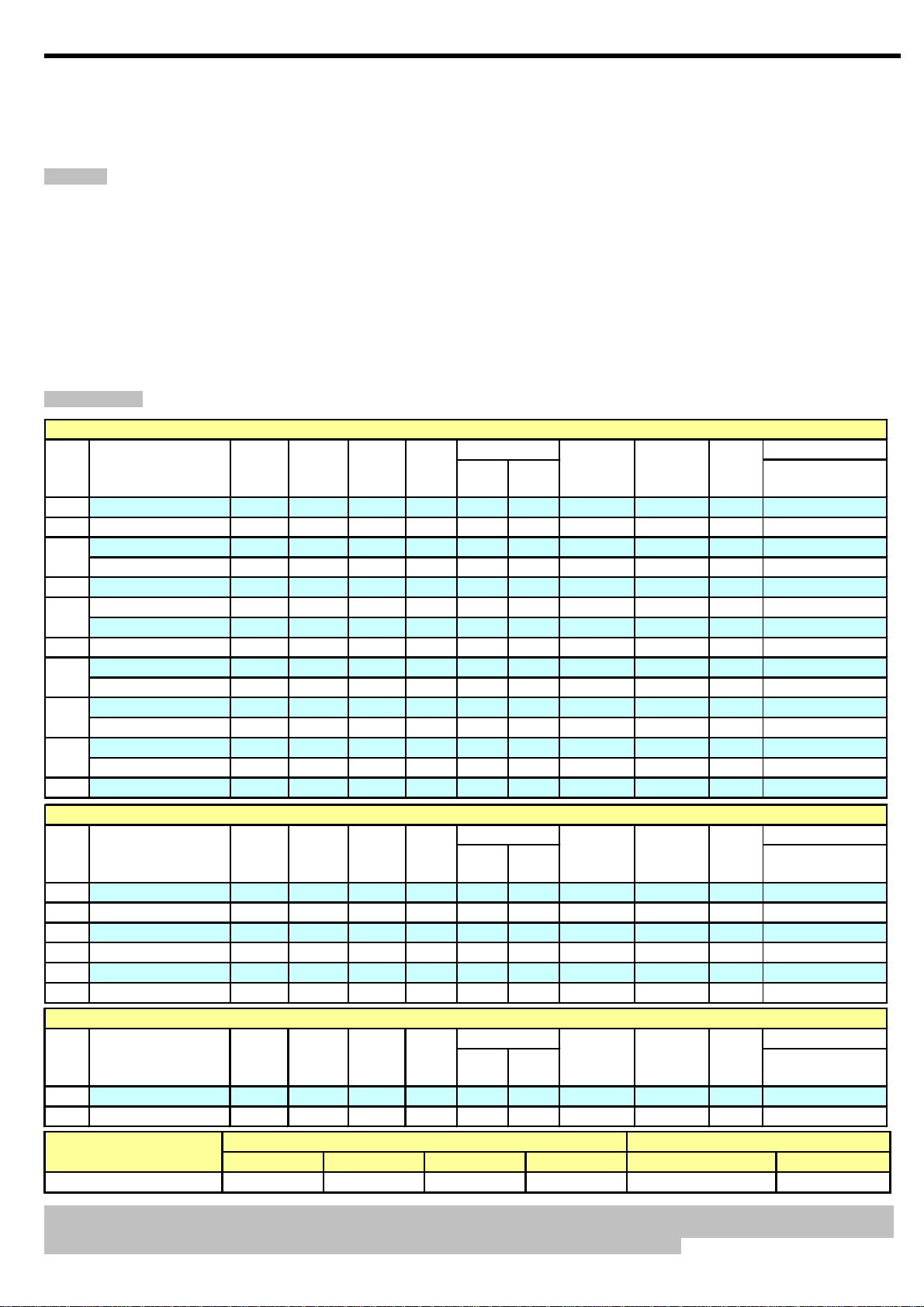
Specifications:
Pentium Series
Class Model Cont.
Current
6A
Pentium-6 6A 8A Linear
10A
Pentium-10 10A 12A Linear
Pentium-12 12A 15A Linear
12A
Pentium-12E 12A 15A Linear
18A
Pentium-18 18A 22A Linear
Pentium-25 25A 35A Linear
25A
Pentium-25-OPTO 25A 35A N/A
30A
Pentium-30 30A 40A Linear
Pentium-40 40A 55A Linear
40A
Pentium-40-OPTO 40A 55A N/A N/A 2-6 5-18 Available N/A 32g 55*28*11
Pentium-60 60A 80A Switch
60A
Pentium-60-OPTO 60A 80A N/A N/A 2-6 5-18 Available N/A 56g 70*31*13
Pentium-80 80A 100A Switch
80A
Pentium-80-OPTO 80A 100A N/A
100A
Pentium-100 100A 120A N/A N/A 2-6 5-18 Available N/A 120g 78*55*15
Burst
Current
(>10s)
BEC
Mode
BEC
Output
5V/0.8
5V/1A
5V/1A
5V/2A
5V/2A
5V/2A
N/A
5V/2A
5V/3A
5V/3A
5V/3A
N/A
NiCd
Programm-
able
Li-ion
Li-poly
NiMH
2-3 5-9 Available N/A 6g 24*12*6
2-4 5-12 Available N/A 9g 27*17*6
2-4 5-12 Available N/A 12g 32*24*8
2-4 5-12 Available N/A 13g 32*24*10
2-4 5-12 Available N/A 19g 45*24*11
2-4 5-12 Available N/A 22g 45*24*11
2-4 5-12 Available N/A 21g 45*24*11
2-4 5-12 Available N/A 25g 45*24*11
2-5 5-15 Available N/A 33g 55*28*12
2-6 5-18 Available N/A 60g 70*31*14
2-6 5-18 Available N/A 62g 70*31*14
2-6 5-18 Available N/A 58g 70*31*13
Balance
Discharge
Protection
WeightBattery Cell User
, real time monitors
Size
L*W*H
Guard Series
Class Model Cont.
Current
18A Guard-18 18A 22A
25A Guard-25 25A 35A
30A Guard-30 30A 40A
40A Guard-40 40A 55A Switch 5V/3A 2-5 5-15 Available Available 40g 55*28*15
60A Guard-60 60A 80A Switch 5V/3A 2-6 5-18 Available Available 65g 70*31*14
80A Guard-80
80A 100A
Burst
Current
(>10s)
BEC
Mode
Linear
Linear
Linear
Switch 5V/3A 2-6 5-18 Available Available 67g 70*31*14
BEC
Output
5V/2A 2-4 5-12 Available Available 24g
5V/2A 2-4 5-12 Available Available 27g 45*26*12
5V/2A 2-4 5-12 Available Available 29g 45*26*12
Battery Cell User
Li-ion
Li-poly
NiMH
Programm-
NiCd
able
Balance
Discharge
Protection
Weight
Size
L*W*H
45*26*11
Combo Products
Class Model Cont.
Current
25A Pentium-25A + UBEC 25A 35A
30A Pentium-30A + UBEC 30A 40A
BEC Output Capability
Burst
Current
(>10s)
Switch
Switch
Linear Mode BEC (5V/2A)
2S Li-Poly 3S L i-Poly 2S — 4S Li-Poly
Standard micro servos(Max.) 5 4
BEC
Mode
BEC
Output
5V/2A 2-4 5-12 Available
5V/2A 2-4 5-12 Available
Battery Cell
Li-ion
Li-poly
NiMH
NiCd
User
Programm-
able
4S Li-Poly 5S Li-Poly
32
Balance
Discharge
Protection
N/A
N/A
IMPORTANT ! For ESC named “xxx-xxx-OPTO” or without a built-in BEC, an UBEC (Ultimate-BEC) or an individual battery pack
should be used to power the receiver. And an individual battery pack is needed to power the program card when setting the
programmable value of such ESCs, please read the user manual of program card fo r reference.
Weight
29g 45*24*11(ESC)
32g 45*24*11(ESC)
Size
L*W*H
Switch Mode BE C (5V/3A )
5S Li-Poly
5
4
- 1 -
Page 2
Manual of Sensorless Brushless Motor Speed Controller
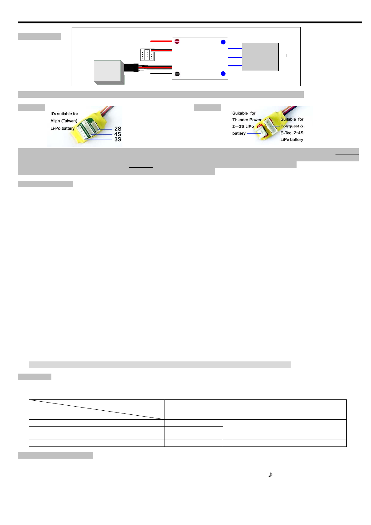
Wiring Diagram:
Connect with balance
charge connector on
battery pack
Receiver
Power +
Power -
Red
Black
BATTERY
ESC
GUARD-25A
Electronic Speed Controller
BRUSHLESS MOTOR
brushless
motor
MOTOR
Lithium Battery Balance Discharge Monitoring and Protection (BDMP) Adapter For the “Guard” Series ESC:
We provide 2 kinds of Lithium Battery Balance Discharge Monitoring and Protection (BDMP) Adapters for user to choose.
Adapter #1 Adapter #2
VERY IMPORTANT! You MUST connect the BDMP adapter with the balance charge connector on battery pack BEFORE
connecting the main power lead to ESC. An d if you use banana-shape connectors on main power wires (Input wires), please
connect the black wire (negative polarity) BEFORE red wire (positive polarity). So the right sequence is:
BDMP Adapter → BLACK wire of main power → RED wire of main power
Feature Explanation:
1. Brake Settings:Enabled / Disabled, default is Disabled
2. Battery Type:Li-xx(Li-ion or Li-Poly) / Ni-xx(NiMH or NiCd),default is Li-xx.
3. Low Voltage Protection Mode(Cut-Off Mode): Soft Cut-Off (Gradually reduces the output power) or Cut-Off (Immediately stops
output power). Default is Soft Cut-Off.
4. Low Voltage Protection Threshold(Cut-Off Threshold):Low / Medium / High, default is Medium.
When NOT using balance discharge monitoring and protection function (i.e. Not plugging the balance charge connector
into the BDMP socket on the Guard series ESC, the ESC only monitors the voltage of the whole battery pack )
1) For lithium batteries, the number of battery cells is calculated automaticall y. Low / medium / high cutoff voltag e for each
cell is: 2.6V/2.85V/3.1V. For exam ple: For a 3 cell lithium pack, when medium cutoff voltage is set, the cut-off voltage will
be: 2.85*3=8.55V.
2) For nickel batteries, low / medium / high c utoff voltages are 0%/45%/60% of the startup voltage (i.e. the initial voltage of
battery pack), and 0% means low voltage cut-off function is disabled. For example: For a 10 cell NiMH battery, fully
charged voltage is 1.44*10=14.4V, when “medium” cut-off voltage is set, the cut-off voltage will be:14.4*45%=6.5V。
When using balance discharge monitoring and protection function (i.e. Plugging the balance charge connector on battery
pack into the BDMP socket on the Guard series ESC, the ESC monitors not only the voltage of the whole battery pack but also
the voltage of each cell). For lithium battery,low / medium / high cut off voltage for each cell is: 2.6V/2.85V/3.1V. When the
voltage of any cell in battery pack is lower than the cut-off threshold, the protection function is activated.
5. Startup Mode:Normal /Soft /Super-Soft, default is Normal.
Normal is preferred for fixed-wing aircraft. Soft or Super-soft are preferred for helicopters. The initial acceleration of the Soft and
Super-Soft modes are slower in comparison, usually taking 1 second for Soft startup or 2 seconds for Super-Soft startup from initial
throttle advance to full throttle. If the throttle is closed (throttle stick moved to bottom) and opened again (throttle stick moved to top)
within 3 seconds of the initial startup, the restart-up will be temporarily changed to normal mode to get rid of the chances of a crash
caused by slow throttle response in aerobatic flight.
6. Timing:Low / Medium / High, default is Low.
Usually , low timing can be used for most motors. But for high efficiency , we recommend the Low timing for 2 poles motor and Medium
timing for 6 poles and above. For higher speed, High timing can be chosen.
Important! After changing the timing setting, please test your RC model on ground prior to flight!
Special Note
Some high KV out-runner motors have very special construction, the space between each magnet is ver y large, and many ESCs can’t
drive these motors. After much testing, our ESCs have proven to work very well with these types of motors. Some RC enthusiasts still have
several questions about the programming value for these special motors. Therefore, we have provided some suggestions as follows:
Programmable Value Suggestion
Timing Startup Mode
Motor
Generic in-runner motor Low
Generic out-runner motor Low or Medium
Usually, aircraft use “normal” startup mode
and helicopter use “super-soft” startup mode
Align 420LF (Made in TAIWAN, out-runner) High (MUST)
450TH (Made in TAIWAN, out-runner) Low Soft (MUST)
Begin To Use Your New ESC
Please start the ESC in the following sequences:
1. Move the throttle stick to the bottom position and then switch on the transmitter.
2. Connect the battery pack to the ESC, the ESC begins the self-test process, a special tone “ 123” is emitted, which means the
voltage of the battery pack is in normal range, and then N “beep” tones will be emitted, means the number of lithium battery cells.
Finally a long “beep------” tone will be emitted, which means self-test is OK, the aircraft/helicopter is ready to go flying.
If nothing is happened, pleas e check the battery pack and all the connections;
- 2 -
Page 3

Manual of Sensorless Brushless Motor Speed Controller
If a special tone “
because the throttle channel of your transmitter is reversed, please set it correctly;
If the very rapid “beep-beep-, beep-beep-” tones is emitted, means the input voltage is too low or too high, please check your
battery’s voltage.
3. “VERY IMPORTANT!” Because different transmitter has different throttle range, we strongly suggest you using the “Throttle Range
Setting Function” to calibrate throttle range. Please read the instruction on page 4------“Throttle Range Setting”.
Alert Tone
1. Input voltage is abnormal: The ESC begins to check the voltage when the battery pack is connected, if the voltage is not in the
acceptable range, such an alert tone will be emitted: “beep-beep-, beep-beep-,beep-beep-” (Every “beep-beep-” has a time interval of
about 1 second. )
2. Throttle signal is abnormal: When the ESC can’t detect the normal throttle signal, such an alert tone will be emitted: “beep-, beep-,
beep-”. (Every “beep-” has a time interval of about 2 seconds)
3. Throttle stick is not in the bottom position: When the throttle stick is not in bottom (lowest) position, a very rapid alert tone will be
emitted: “beep-, beep-, beep-”. (Every “beep-” has a time interval of about 0.25 second.)
Protection Function
1. Start up protection: If the motor fails to start within 2 seconds of throttle application, the ESC will cut-off the output power. In this case,
the throttle stick MUST be moved to the bottom again to restart the motor. (Such a situation happens in the following cases: The
connection between ESC and motor is not reliable, the propeller or the motor is blocked, the gearbox is damaged, etc.)
2. Over-heat protection: When the temperature of the ESC is over 110℃, the ESC will reduce the output power.
3. Throttle signal loss protection: The ESC will reduce the output power if throttle signal is lost for 1 second, further loss for 2 seconds
will cause its output to be cut-off completely.
Program example
Setting “Start Mode” to “Super-Soft”, i.e. value #3 in the programmable item #5
1. Enter Program Mode
Switch on transmitter, move throttle stick to top position, connect battery pack to ESC, wait for 2 seconds, “beep-beep” tone should
be emitted. Then wait another 5 seconds, special tone like “
2. Select Programmable Items
Now you’ll hear 8 tones in loop. When a long “beep------” tone is emitted, move throttle stick to bottom to enter the “Start Mode”
3. Set Item Value (Programmable Value)
“Beep-”, wait for 3 seconds; “Beep-beep-”, wait for another 3 seconds; then you’ll hear “beep-beep-beep”, move throttle stick to top
position, then a special tone “
4. Exit Program Mode
After the special tone “
Trouble Shooting
Trouble Possible Reason Action
After power on, motor does not work, no
sound is emitted
After power on, motor does not work,
such an alert tone is emitted:
“beep-beep-, beep-beep-,beep-beep-”
(Every “beep-beep-” has a time interval
of about 1 second)
After power on, motor does not work,
such an alert tone is emitted:
“beep-, beep-, beep- ”(Every “beep-” has
a time interval of about 2 seconds)
After power on, motor does not work,
such a alert tone is emitted:
“beep-, beep-, beep-” (Every “beep-” has
a time interval of about 0.25 second)
After power on, motor does not work, a
special tone “
beep tone (beep-beep-)
The motor runs in the opposite direction The connection between ESC and
The motor stop running while in working
state
Random stop or restart or irregular
working state
” is emitted after 2
” is emitted after 2 beep tones (“beep-beep-”), means the ESC has entered the program mode, it is
” should be emitted, which means program mode is entered.
” is emitted, now you have set the “Start Mode” item to the value of “Super-Soft”
”, move throttle stick to bottom within 2 seconds.
The connection between battery
pack and ESC is not correct
Input voltage is wrong, too high or
too low.
The balance charge connector is
not located properly in BDMP
adapter.
Throttle signal is irregular Check the receiver and transmitter
The throttle stick is not in the
bottom( lowest) position
Direction of the throttle channel is
reversed, so the ESC has entered
the program mode
the motor need to be changed.
Throttle signal is lost Check the receiver and transmitter
ESC has entered Low Voltage
Protection mode
Some Connections are not reliable Check all the connections: battery pack connection,
There is strong Electro - Magnetic
interference in flying field.
Check the power connection.
Replace the connector.
Check the voltage of battery pack
Check the connection of the balance charge
connector and the BDMP adapter.
Check the cable of throttle channel
Move the throttle stick to bottom
Set the direction of throttle channel correctly
Swap any two wire connections between ESC and
motor
Check the cable of throttle channel
Land RC model as soon as possible, and then
replace the battery pack
throttle signal cable, motor connections, etc.
Reset the ESC to resume normal operation. If the
function could not resume, you might need to move
to another area to fly.
- 3 -
Page 4

Manual of Sensorless Brushless Motor Speed Controller
r
Normal startup procedure:
Move throttle
stick to
bottom and
then switch
on transmitte
Throttle range setting: (Throttle range should be reset whenever a new transmitter is being used)
Switch on
transmitter,
move throttle
stick to top
Program the ESC with your transmitter (4 Steps):
1. Enter program mode
2. Select programmable items
3. Set item’s value (Programmable value)
4. Exit program mode
1. Enter program mode
1) Switch on transmitter, move throttle stick to
top , connect the battery pack to ESC
2) Wait for 2 seconds, the motor should emit
special tone like “beep-beep-”
3) Wait for another 5 seconds, special tone like
“
program mode is entered
Connect battery
pack to ESC,
special tone like
“
123” means
power supply is OK
.
Connect battery
pack to ESC,
and wait for
about 2 seconds
” should be emitted, which means
Several “beep-” tones
should be emitted,
presenting the number
of lithium battery cells
“Beep-Beep-” tone
should be emitted,
means throttle range
highest point has been
correctly confirmed
When self-test is
finished, a long
“beep-----”tone
should be emitted
Move throttle stick to the
bottom, several “beep-” tones
should be emitted, presenting
the number of battery cells
2. Select programmable items:
After entering program mode, you will hear 8 tones in a loop in the
following sequence. If you move the throttle stick to bottom within 3
seconds after one kind of tones, this item will be selected.
1. “beep” brake (1 short tone)
2. “beep-beep-” battery type (2 short tone)
3. “beep-beep-beep-” cutoff mode (3 short tone)
4. “beep-beep-beep-beep-” cutoff threshold (4 short tone)
5. “beep-----” startup mode (1 long tone)
6. “beep-----beep-” timing (1 long 1 short)
7. “beep-----beep-beep-” set all to default (1 long 2 short)
8. “beep-----beep-----” exit (2 long tone)
Note: 1 long “beep-----” = 5 short “beep-”
Move throttle stick
upwards to go flying
A long “Beep-” tone should
be emitted, means throttle
range lowest point has
been correctly confirmed
3. Set item value (Programmable value):
You will hear several tones in loop. Set the value matching to a tone by moving throttle stick
to top when you hear the tone, then a special tone “
and saved. (Keeping the throttle stick at top, you will go back to step 2 and you can select
other items; Moving the stick to bottom within 2 seconds will exit program mode directly)
” emits, means the value is set
Tones
Items
“beep-”
1 short tone
“beep-beep-”
2 short tones
“beep-beep-beep”
3 short tones
Brake
Battery type
Cutoff mode
Off On
Li-ion / Li-poly NiMH / NiCd
Soft-Cut Cut-Off
Cutoff threshold
Start mode
Timing
Low Medium High
Normal Soft Super soft
Low Medium High
4. Exit program mode
There are 2 ways to exit
program mode:
1. In step 3, after special
tone “
move throttle stick to
the bottom position
within 2 seconds.
”, please
2. In step 2, after tone
“beep-----beep-----”(ie.
The item #8), move
throttle stick to bottom
within 3 seconds.
- 4 -
 Loading...