

SKUTCH CK-1P4 User Manual
"Telecommunication Products to solve Telecommunication Problems"
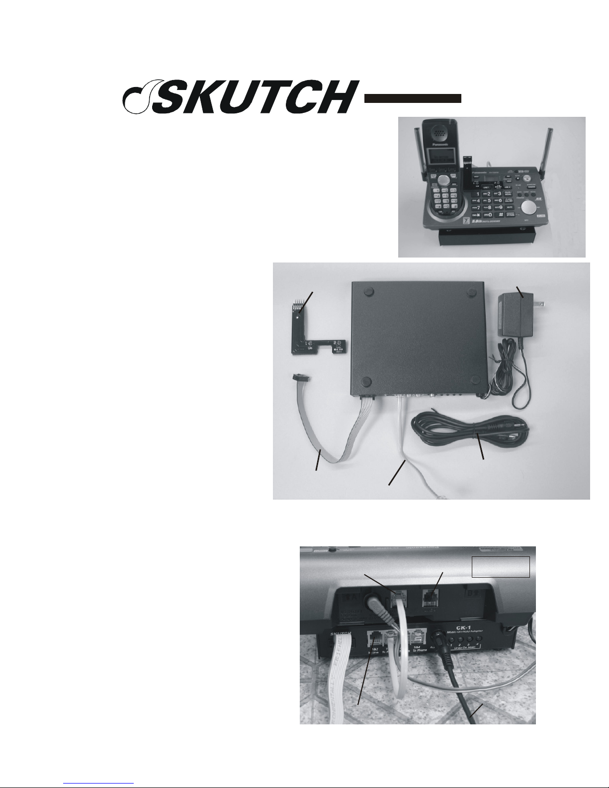
Power Cube
Connect to Wall Jack
CK-1P4
Promotion-On-Hold Module
(For Panasonic
KX-TG6700B and KX-TG6702B)
Introduction
Thank you for purchasing the
Skutch CK-1P4 Promotion-OnHold Module. The CK-1P4 is a
true plug and play device. The unit
does not require any "Learning" to
operate. When a call is placed ON
HOLD from the base set, or any one
of the cordless phones, the caller
will hear the Promotion-On-Hold
audio. When the line is reanswered, the audio automatically
stops. It's that simple!
NOTE: You can NOT use the
“Transfer to Answering System”
with this module. This is ONLY
when you transfer a call to the
answering device, AFTER you have already answered and talked to the person! When a
call is answered by the answering device, the Answering System works perfectly.
Sensor Board
Sensor Cable
Short Mod Cord
CK1P4
Black Box
Audio Cord (For CD Player ONLY!)
Installation
1- Position the CK-1P4 black box under
the base telephone with the jacks facing
towards the back of the phone. (See Fig.
1).
Page 1 of 4
LINE 1 /2
LINE 2
Fig. 1
To Audio Source
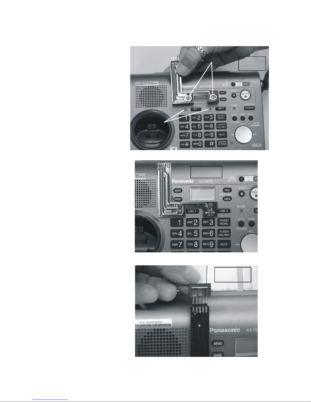
Silver Dots
Fig. 2
Sensor Board Mounted
2- Connect the short modular
cord [1&2 Phone on CK-1] to
[LINE 1/2 on Phone].
3- Connect the audio cord from
your audio source, to the
AUDIO IN jack on the back of
the CK-1 box. For DIGITAL
PLAYERS use the cable that
comes with the player.
4- Connect a MOD cord from
Telephone Wall Jack 1&2 to
[1&2 Line on CK-1].
5- Make sure that the surface area
of the base phone, where the
sensor board is to be mounted, is
clean and free of all dust and oil
film. Locate the CK-1P4
"SENSOR BOARD", peel off the
green/white protector papers from
the bottom of the sensor board,
and carefully place it OVER the
LINE 1 and LINE 2 lights on the
Panasonic base set as shown in
Fig. 2 and Fig. 3. Make sure that
you align the SILVER DOTS on
the Sensor Board, directly over
the IN-USE lights on the phone.
6- Connect the Sensor Cable to
the Sensor Board as shown in Fig.
4.
7- Connect the POWER CUBE
from the CK-1 Black Box to
115VAC power. That's it!
Align by centering Silver Dots
over IN USE lights on phone.
IN-USE
Lights
Fig. 3
Fig. 4
Testing the System:
1- Pickup line 1 on your
telephone. The No."1" LED on
the CK-1P4 Sensor Board should
Page 2 of 4
 Loading...