

SK Telesys SKSN C30 CO, SKSN C24 CO Users manual

CDMA REPEATER
R
R
CDMA RF
EPEATE
USER MANUAL
Version 1.0
2007

CDMA REPEATER
Contents
1. OVERVIEWS..............................................................................................................8
2. COMPONENTS...........................................................................................................9
2.1 PACKING LIST ......................................................................................................9
2.2 SYSTEM QUICK VIEW .......................................................................................10
2.3 WARNING AND HAZARDS
3. FEATURES AND SPECIFICATION OF SYSTEM....................................................13
3.1 ELECTRICAL SPECIFICATION...........................................................................13
3.2 MECHANICAL SPECIFICATION .........................................................................14
3.3 ENVIRONMENT SPECIFICATION ......................................................................14
3.4 FREQUENCY USED ...........................................................................................15
4. SYSTEM BLOCK DIAGRAM....................................................................................16
4.1 BLOCK DIAGRAM...............................................................................................16
4.2 BLOCK DIAGRAM DESCRIPTION .....................................................................16
5. SYSTEM OVERVIEW...............................................................................................18
5.1 CONSTRUCTION AND FEATURES OF SYSTEM ..............................................18
5.1.1 PSU (POWER SUPPLY UNIT)..........................................................................19
5.1.2 CONTROLLER ....................................................................................................19
5.1.3 UP / DOWN CONVERTER ..................................................................................20
5.1.4 FILTER.................................................................................................................21
5.1.5 PAU(POWER AMPLIFIER UNIT).........................................................................21

CDMA REPEATER
5.1.6 ISOLATION CHECK MODULE............................................................................21
5.1.7 CABINET .............................................................................................................21
5.2 ADDITIONAL FUNCTIONS .................................................................................24
5.2.1 AGC FUNCTION.................................................................................................24
5.2.2 SHUTDOWN FUNCTION ...................................................................................25
5.2.3 OSCILLATION CHECK FUNCTION...................................................................25
5.2.4 OSCILLATION SHUTDOWN FUNCTION ..........................................................26
6. SYSTEM INSTALLATION GUIDE ..........................................................................27
7. WEB GUI INSTALLATION GUIDE............................................................................29
7.1 PROGRAM SETUP .............................................................................................29
7.2 WEB GUI CONNECTION ....................................................................................31
7.3 MONITOR/CONTROL OF WEB GUI STATE .......................................................33
7.3.1 ACCOUNT ...........................................................................................................34
7.3.2 USER REGISTRATION ......................................................................................35
7.3.3 USER DELETION AND MODIFICATION ..........................................................35
7.3.4 ALARM HISTORY...............................................................................................36
7.3.5 CONFIG...............................................................................................................37
7.3.6 UP LOAD ............................................................................................................37
8. MAINTENANCE GUIDE............................................................................................40
8.1 CONFIRMATION OF SYSTEM COMPONENTS .................................................40
8.2 CAUTIONS ON SYSTEM INSTALLATION ..........................................................40

CDMA REPEATER
9. SYSTEM SET UP AND INSPECTION ......................................................................41
9.3.1 INSPECTION OF REPEATER ...........................................................................42
9.3.2 FACILITY INSPECTION......................................................................................43
10 . WARRANTY AND REPAIR POLICY......................................................................44
☎ CONTACT INFORMATION......................................................................................46
Information in this document is subject to change without notice.
SK Telesys Co., LTD. All rights reserved.

CDMA REPEATER
- Lists of Figures -
< Fig. 1 > Configuration of iDEN Network.............................................................................. 8
< Fig. 2 > Components of CDMA Repeater ........................................................................... 9
< Fig. 3 > Front & Back View of CDMA Repeater.............................................................. 10
< Fig. 4 > Side View of CDMA Repeater............................................................................. 10
< Fig. 5 >Bottom View of CDMA Repeater ...........................................................................11
< Fig. 6 > CDMA Frequency.................................................................................................. 15
< Fig. 7 > Block Diagram....................................................................................................... 16
< Fig. 8 > Internal Construction of CDMA Repeater ........................................................... 18
< Fig. 9 > Bottom View of CDMA RF Repeater .................................................................. 19
< Fig. 10 > Latch Structure .................................................................................................... 22
< Fig. 11 > Hinge Functions .................................................................................................. 22
< Fig. 12 > Swing Handle Function ...................................................................................... 23
< Fig. 13 > Guide for Wrench Prevention ............................................................................ 24
< Fig. 14 > Mounting Sequence of the CDMA Repeater.................................................... 28
< Fig. 15 > Local Area Connection Properties..................................................................... 29
< Fig. 16 > Internet Protocol(TCP/IP) Properties.................................................................. 30
< Fig. 17 > Local Area Connection Status-1 ........................................................................ 30
< Fig. 18 > Local Area Connection Status-2 ........................................................................ 30
< Fig. 19 > Web GUI Initial Screen ...................................................................................... 31
< Fig. 20 > Monitoring Screen of i CDMA Repeater State................................................. 32
< Fig. 21 > Control Screen of CDMA Repeater State......................................................... 32
< Fig. 22 > Input Range Excess Message........................................................................... 33
< Fig. 23 > Set Up Completion Message............................................................................. 33
< Fig. 24 > Mode Select ........................................................................................................ 33
< Fig. 25 > Polling Time......................................................................................................... 34
< Fig. 26 > Function Button ................................................................................................... 34
< Fig. 27 > Logout .................................................................................................................. 34
< Fig. 28 > Account Page...................................................................................................... 35
< Fig. 29 > User Registration ................................................................................................ 35
< Fig. 30 > Deletion and Change of User ........................................................................... 36
< Fig. 31 > Alarm History.......................................................................................................36
< Fig. 32 > Configuration Information of System ................................................................. 37

CDMA REPEATER
< Fig. 33 > Upload Page ....................................................................................................... 37
< Fig. 34 > File Selection....................................................................................................... 38
< Fig. 35 > Upload Arrangement ........................................................................................... 38
< Fig. 36 > Key Value Error .................................................................................................. 39
< Fig. 37 > Upload Completion.............................................................................................. 39

CDMA REPEATER
- Lists of Tables -
<Table 1 > Packing List ............................................................................................................ 9
<Table 2 > System Features .................................................................................................. 13
<Table 3 > Figure and Function............................................................................................. 14
<Table 4 > Environmental specifications................................................................................ 14
<Table 5 > CDMA Frequency................................................................................................. 15
CDMA REPEATER
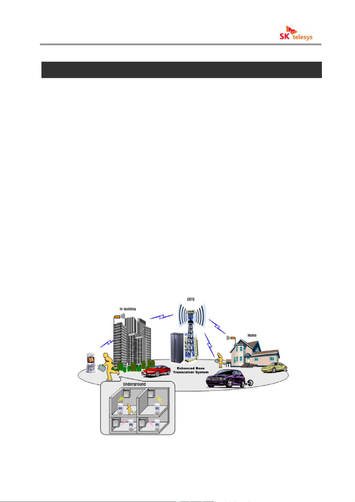
1. Overviews
The RF repeater for CDMA is an economical RF repeater to enable customers who want
extension of communication ranges to extend communication ranges by installing repeaters in
the building inside, parking lots at the wave shade region, etc.
The RF repeater for CDMA is designed to enable users to select their desired bands(at
most 20MHz) among the CDMA 65MHz band. The CDMA repeater is excellent in the frequency
selection level and minimizes interference with other signals.
Controller of the CDMA RF repeater has a local repeater control function to constantly
The
manage and control the repeaters for stable services of the repeaters installed at sites and a
remote repeater control function to support remote monitoring and control using a repeater
integrated-monitoring system.
The CDMA RF repeater is interlocked with a CDMA repeater integrated-monitoring system
using a modem in order to be interlocked with the CDMA repeater integrated-monitoring system.
The internal structure of a CDMA repeater composes a DL(Down Link) converter and UL(Up
Link) converter as one-module for optimum size and efficiency and consists of a PSU(Power
Supply Unit), filter unit, NMS module, and PAU(Power Amplifier Unit).
All modules except PAU were commonly used for economy and efficiency of operation and
enabled system output change only with replacement of PAU and PSU.
< Fig. 1 > Configuration of iDEN Network
CDMA REPEATER
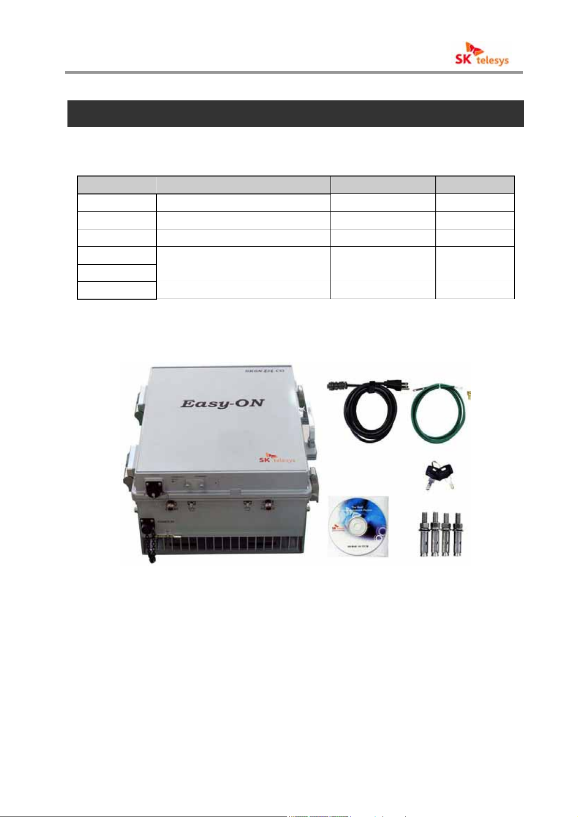
2. Components
2.1 Packing List
No Description
Quantity Remark
1 CDMA Repeater 1
2 AC Power Cable 1
3 Ground Cable 1
4
5 KEY 2
6
Bolts to fix the holder
CD 1
<Table 1 > Packing List
4
Manual
< Fig. 2 > Components of CDMA Repeater
CDMA REPEATER
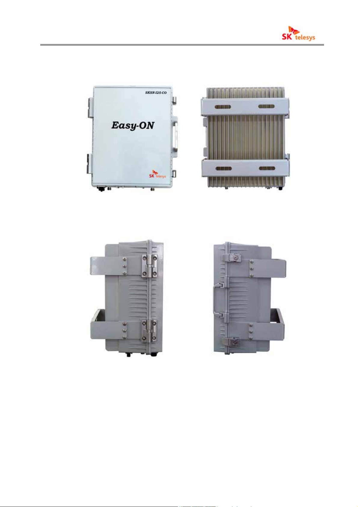
2.2 System Quick View
< Fig. 3 > Front & Back View of CDMA Repeater
< Fig. 4 > Side View of CDMA Repea ter
CDMA REPEATER
< Fig. 5 >Bottom View of CDMA Repeater
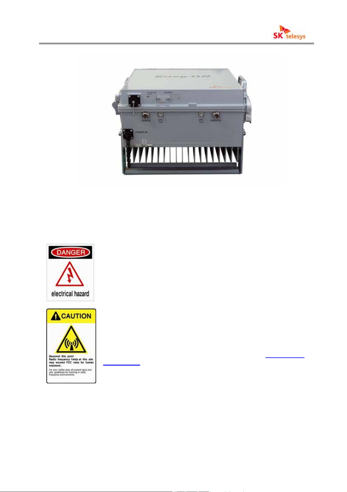
2.2 Warning and Hazards
WARNING! ELECTRIC SHOCK
Danger of electric shock!
Switch off while( it is ) maintained and inspected!
WARNING! EXPOSURE TO RF
Working with the repeater while in operation, may expose the
technician to RF electromagnetic fields that exceed FCC rule
s for human exposure. Visit the FCC website at www.fcc.gov
/oet/rfsafety to learn more about the effects of exposure to R
F electromagnetic fields.

CDMA REPEATER
RF EXPOSURE & ANTENNA PLACEMENT
Actual separation distance is determined upon gain of antenna
used.
Please maintain a minimum safe distance of at least 20 cm whi
le operating near the donor and the service antennas. Also, th
e donor antenna needs to be mounted outdoors on a permane
nt structure.
FCC STATEMENT
This equipment has been tested and found to comply with the
limits for a Class A digital device, pursuant to Part 15 of the F
CC Rules. These limits are designed to provide reasonable prot
ection against harmful interference when the equipment is oper
ated in a commercial environment. This equipment generates, u
ses, and can radiate radio frequency energy and, if not installe
d and used in accordance with the instruction manual, may ca
use harmful interference to radio communications.
Operation of this equipment in a residential area is likely to ca
use harmful interference in which case the user will be require
d to correct the interference at own expense.
Warning!
This equipment generates or uses radio frequency energy.
Changes or modifications to this equipment may cause harmf
ul interference unless the modifications are expressly approve
d in the instruction manual. The user could lose the authority
to operate this equipment if an unauthorized change or modi
fication is made.
CDMA REPEATER
3. Features and Specification of System
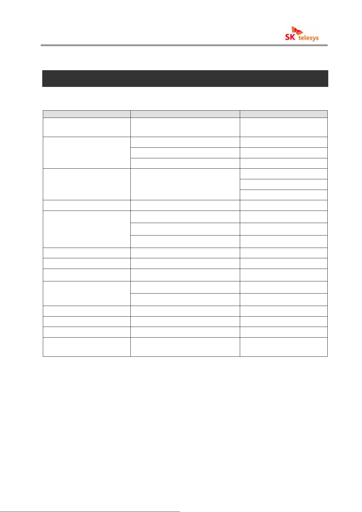
3.1 Electrical Specification
Item Specification Remark
Frequency Range
Downlink : 1930 ~ 1995 MHz
Uplink : 1850 ~ 1915 MHz
Amplifier Gain /
Output Power per
Input Level -16 ~ -56dBm / Total
Ripple ± 1.25dB
Gain Control Range
Roll offs ∆50 dBc or more @ Band Edge± 1.625 MHz
Spurious RF Emission -13dBm or less
Propagation Delay 13 us or less
Noise Figure
VSWR 1.5 : 1
Channel
40 dB(1dB/Step±0.5dB or less) ※ CDMA (80/24)
46 dB(1dB/Step±0.5dB or less)
53 dB(1dB/Step±0.5dB or less)
80 dB / 24 dBm ※ CDMA (80/24)
86 dB / 30 dBm ※ CDMA (86/30)
93 dB / 37 dBm ※ CDMA (93/37)
※ CDMA (80/24)
※ CDMA (86/30)
※ CDMA (93/37)
※ CDMA (86/30)
※ CDMA (93/37)
4.5 dB or less @ Max. Gain (Uplink)
12 dB or less @ Min.. Gain (Uplink)
Input/output connector N-Type (Female)
Input/output impedance 50Ω
Power 108 ~ 127 VAC, 60Hz
<Table 2 > System Features
Option※ -40 to -60VDC
20 to 30 VDC
CDMA REPEATER
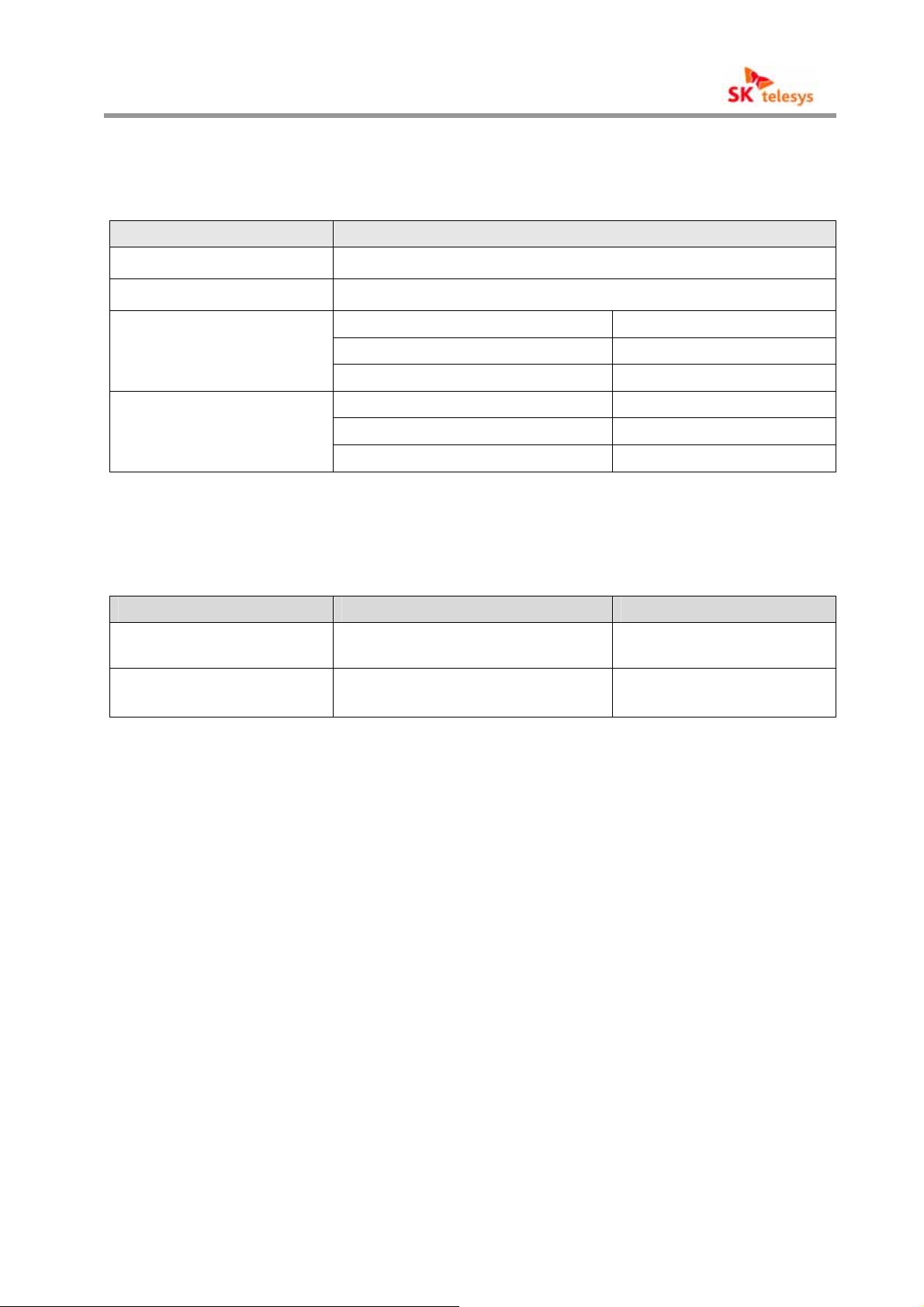
3.2 Mechanical Specification
Item Specification
Cabinet Indoor Type
RF Connector Type (IN/OUT) N-Type Female
Dimension
(H*W*D)
Weight
<Table 3 > Figure and Function
3.3 Environment Specification
Item Specification Remark
Working temperature/
working humidity
Power 108 ~ 127 VAC, 60Hz
<Table 4 > Environmental specifications
390 * 326 * 175 mm ※ CDMA (80/24)
390 * 326 * 195 mm ※ CDMA (86/30)
390 * 326 * 225 mm ※ CDMA (93/37)
18.5Kg ※ CDMA (80/24)
20.0Kg ※ CDMA (86/30)
21.5Kg ※ CDMA (93/37)
-10 ~ 50 / ℃℃5 % ~ 95%
Temperature and humidity
around cabinets
Option※ -40 to -60VDC
20 to 30 VDC
 Loading...