

Page 1
~ 1 ~
FS 4510
Version 1.1
Page 2
~ 2 ~
1. Installation
Gefahr für Personen durch einen elektrischen Schlag. Verbrennungsgefahr, Geräteschäden und
Fehlfunktionen. Bei der Installation sind die Richtlinien der VDE 0100 und VDE 0800 einzuhalten.
(Deutschland)
Gegenmaßnahmen:
Schalten Sie zu Beginn der Arbeiten alle Spannungsführenden Leitungen frei.
Sichern Sie die ausgeschalteten Leitungen gegen irrtümliches Wiedereinschalten.
Stellen Sie Spannungsfreiheit durch Messung fest.
Decken Sie benachbarte, unter Spannung stehende, oder leitfähige Teile ab.
Alle Arbeiten und elektrische Anschlüsse müssen den nationalen Bestimmungen des jeweiligen
Landes entsprechen und von entsprechend ausgebildetem Fachpersonal durchgeführt werden.
Bei Geräten mit 230-V-Anschluss ist die DIN VDE 0100 zu beachten und einzuhalten.
2. Klemmenbezeichnung
Klemme
Bezeichnung
a
BUS-Klemme
b
BUS-Klemme
E+
Etagenklingel
E-
Etagenklingel
P
Potenzialfreier Kontakt
Page 3
~ 3 ~
3. Montageanleitung FS4510
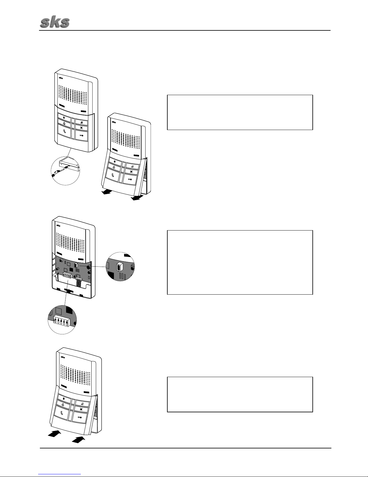
Mit einem Schraubenzieher vorsichtig den unteren
Klipp eindrücken und die komplette Front abnehmen.
Aufputz Montage:
Mit Dübel und Schrauben das Hinterteil der Sprechstelle an der Wand befestigen. Dabei auf das Kabel
achten! Verbinden Sie das Kabel mit der
Anschlußklemme.
Ziehen Sie vorsichtig den roten Steckverbinder ab.
Page 4
~ 4 ~
Montageanleitung FS4510 (Fortsetzung)
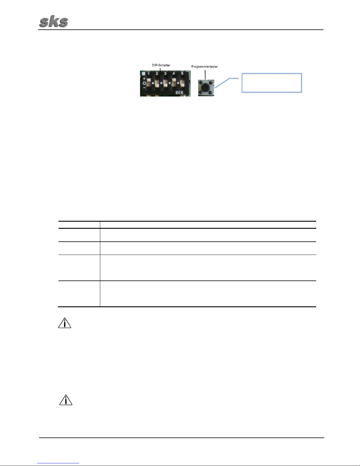
Unterputz Montage:
Mit zwei Schrauben das Hinterteil der Sprechstelle an
der Unterputzdose befestigen. Dabei auf das Kabel
achten! Verbinden Sie das Kabel mit der
Anschlußklemme.
Stecken Sie den roten Steckverbinder wieder auf.
Achten Sie dabei auf die Polung. Anschließend das
Frontteil auf das Hinterteil drücken, bis die Klipps
einrasten. Achten Sie dabei darauf, dass keine
blanken Adern die Leiterplatte von hinten berühren
können.
Page 5
~ 5 ~
Montageanleitung FS4510 (Fortsetzung)
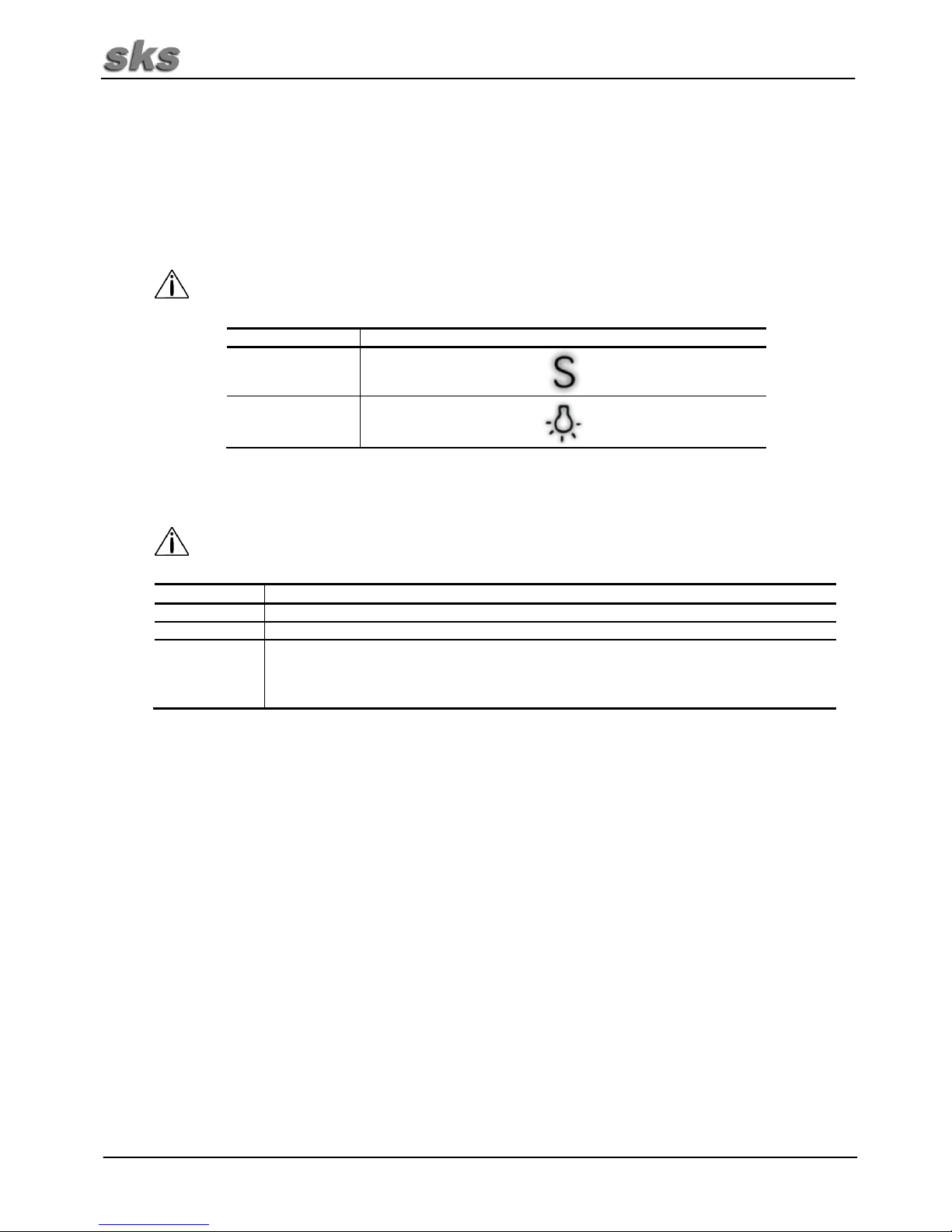
Stellen Sie die SKS-BUS Rufadresse an der
Sprechstelle ein. Jede Adresse ist einem Klingel
Taster an der Türstation zugeordnet. Die Adressen
sind im Anhang aufgeführt. In der Regel wird mit der
SKS-BUS Rufadresse „A1“ begonnen.
Beim Austausch von Sprechstellen stellen Sie den
DIP-Schalter so ein wie bei der zuvor Montierten
Sprechstelle.
Lösen Sie die Tastenabdeckung mit einem
Schraubenzieher.
Drücken Sie die Tastenabdeckung wieder auf die
Sprechstelle, bis die Klipps einrasten.
Page 6
~ 6 ~
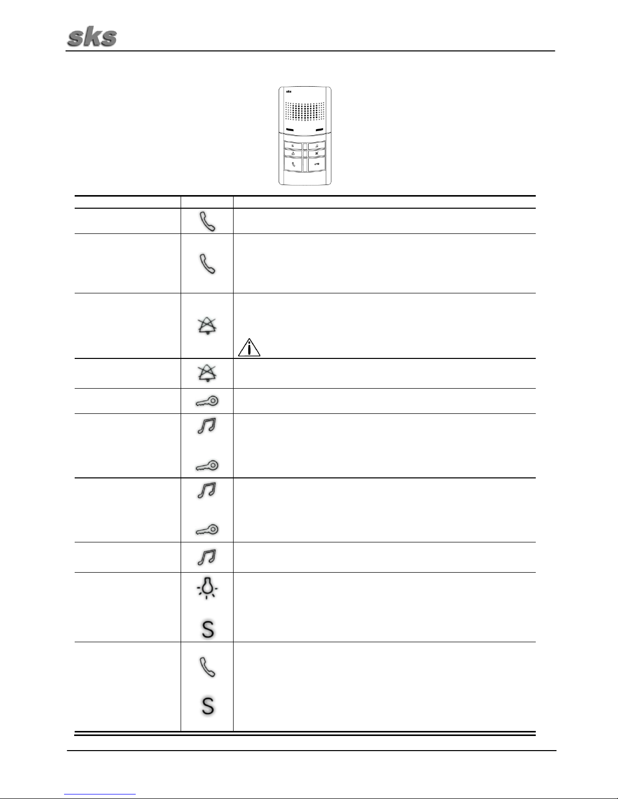
4. Programmierung
4.1 Programmierung von nur einer Rufadresse (ein Klingeltaster für eine Sprechstelle)
Nach der im Anhang befindlichen SKS-BUS Rufadressen Tabelle die gewünschte Rufadresse des
Gerätes am DIP-Schalter einstellen. Jede Rufadresse ist fest einem Klingeltaster in der Türstation
zugeordnet. Die Rufadressenverteilung ist bei SKS Türstationen in der Türstation oder am
Türlautsprecher 4503, 4508 oder 4808 hinterlegt.
4.2 Programmierung von bis zu 4 Rufadressen
(2...4 Klingeltaster für eine Sprechstelle oder Internsprechen)
Die Sprechstelle kann bis zu 4 SKS-BUS Rufadressen für Hausruf-, Internrufadressen oder
Gruppenrufadressen speichern. Die erste Adresse ist dann die Hauptadresse, die als eigene
Gerätekennung übermittelt wird. Auf die bis zu 3 weiteren Rufadressen reagiert die Sprechstelle bei
eingehenden Hausrufen (Klingeltasten der Türstation), Internrufen (Sprechen zwischen zwei
Innensprechstellen) und Gruppenruf (Sprechen von einer Innensprechstelle mit einer von bis zu 4
Innensprechstellen).
Arbeitsschritt
Beschreibung
1
Die Rufadresse am DIP-Schalter einstellen. Die 1. Rufadresse ist der Hausruf
(Klingeltaste an der Türstation).
2
Die Programmiertaste für ca. 5 Sekunden drücken bis der erste Kontrollton
ertönt.
3
Nach diesem Kontrollton ertönt ein kurzer Ton er signalisiert, dass die erste
Rufadresse Programmiert ist.
Die Anzahl der kurzen Töne signalisieren auf welchem Speicherplatz die
Rufadresse gespeichert wurde.
4
Zum Programmieren weiterer Rufadressen wieder holen Sie die Schritte 1 bis 3.
Es können maximal 4 Rufadressen gespeichert werden. Sollen Rufadressen
geändert werden, müssen zuvor wie unter 4.3 Beschrieben alle Rufadressen
gelöscht werden.
Hinweis:
Nach Abschluss der Programmierung den DIP-Schalter wieder auf die Hauptadresse einstellen,
damit eine leichtere Zuordnung der Klingeltaste zur Sprechstelle im Fehlerfall möglich ist.
4.3 Löschen aller Rufadressen
Es können keine einzelnen Rufadressen gelöscht werden. Es werden immer alle Rufadressen
gelöscht. Halten Sie die Programmtaste für ca. 25 Sekunden gedrückt. Während dessen sind mehrere
Kontrolltöne zu hören. Die Löschung ist abgeschlossen, wenn ein 3 Sekunden langer hoher Signalton
ertönt. Lassen Sie jetzt die Programmtaste los. Alle Rufadressen sind jetzt gelöscht.
Hinweis:
Nach dem Löschen der Einprogrammierten Rufadressen ist nur die Adresse, welche am DIPSchalter eingestellt ist wirksam wie unter 4.1 beschrieben.
Nur für
Sonderfunktionen
Page 7
~ 7 ~
5. Einrichten des Internrufs
5.1 Programmieren der Internrufadressen
Internsprechen ermöglicht das Sprechen zwischen zwei Innensprechstellen. Mit der FS4510 kann mit
bis zu 2 Innensprechstellen gesprochen werden. An der FS4510 sind dafür die Licht- und Sondertaste
vorgesehen. Durch Drücken der entsprechenden Taste wird der Internruf abgesetzt.
Hinweis:
Die Funktion „Internruf“ ist nur beim Sondermodel möglich, wenn Sie die Funktion benötigen, teilen Sie
uns das bei Auftragsvergabe mit.
Intersprechstelle
Internsprechtaste(n)
A
B
Ablauf der Programmierung für Internrufadressen:
Hinweis:
Bevor Interrufadressen programmiert werden können, muss die Hausrufadresse wie unter 4.2
beschrieben programmiert sein.
Arbeitsschritt
Beschreibung
1
Die Internrufadresse (Zieladresse) am DIP-Schalter einstellen.
2
Halten Sie die Sprechtaste gedrückt, bis sie den Signalton hören.
3
Halten Sie die Programmiertaste gedrückt und drücken Sie innerhalb von 2
Sekunden die gewünschte Internsprechtaste (Licht - oder Sondertaste) für die
gewünschte Innensprechstelle. Halten Sie die Tastenkombination für ca. 5
Sekunden gedrückt bis Sie den zweiten SIgnalton hören.
5.2 Löschen von Internrufadressen
Es können keine einzelnen Internrufadressen gelöscht werden. Beim Löschen werden immer alle
abgelegten Internrufadressen gelöscht.
Halten Sie die Programmtaste gedrückt und betätigen Sie innerhalt von 2 Sekunden die entsprechende
Internsprechtaste. Die Löschung ist abgeschlossen, wenn ein 3 Sekunden langer hoher Ton ertönt.
Lassen Sie die Tasten los. Alle Rufadressen sind jetzt gelöscht.
Page 8
~ 8 ~
6. Bedienungsanleitung
Funktion
Tasten
Vorgehensweise
Gespräch annehmen
Nachdem das Gerät angeklingelt wurde, die Sprechtaste betätigen.
Wechselsprechen
Ist das Gespräch angenommen, kann mit der Sprechtaste auch das
Freisprechen deaktiviert werden. Solange die Sprechtaste gedrückt wird, ist
das Sprechen von Innensprechstelle zur Türstation möglich. Bei nicht
gedrückter Sprechtaste ist die Sprechrichtung von der Türstation zur
Innensprechstelle. Die Wechselsprech-Funktion ist nur für die Dauer des
Gesprächs aktiv.
Rufabschaltung
Halten Sie die Ruftabschalttaste solange gedrückt (ca.5 Sekunden), bis Sie
die Bestätigungstöne (3 gleichlange Töne) hören. Der Rufton ist jetzt
abgeschaltet. Um auf diesen Zustand hinzuweisen, blinkt die rote LED im
Sekundentakt.
Der Rufton wird automatisch nach 12 Stunden oder nach
Spannungsausfall wieder eingeschaltet.
Rufeinschaltung
Tippen Sie kurz die Rufabschalttaste an. Sie hören einen durchgehenden
hohen Signalton. Der Rufton ist jetzt wieder eingeschaltet.
Tür öffnen
Wurde das Gerät angeklingelt, kann innerhalb von 2,5 Minuten mit der
Türöffnertaste die Tür geöffnet werden.
Hausrufklingelton ändern
+
Die Tontaste gedrückt halten und anschließend die Türöffnertaste innerhalb
von 2 Sekunden kurz drücken. Mit jedem Tastendruck der Türöffnertaste
erklingt eine andere Melodie. Wird die gewünschte Melodie abgespielt,
lassen Sie beide Tasten los.
Es stehen 8 verschiedene Kingeltöne zur Auswahl.
Etagenrufklingelton
ändern
+
Die Tontaste gedrückt halten und anschließend die Türöffnertaste innerhalb
von 2 Sekunden drücken und gedrückt halten. Warten Sie bis die
gewünschte Melodie ertönt. Lassen Sie beide Tasten los.
Es stehen 4 verschiedene Etagenruftöne zur Auswahl.
Klingellautstärke ändern
Die Tontaste gedrückt halten, bis die gewünschte Lautstärke erreicht ist.
Die Lautstärke ist 5-stufig einstellbar.
Licht- und Sondertaste
+
Die Sondertaste „S“ wird standardmäßig mithilfe eines Schaltaktors 4507
zum Schalten verwendet. Des Weiteren wird durch betätigen der Lichttaste
ein interner potentialfreier Kontakt auf der Sprechstelle geschlossen.
Die Lichttaste kann optional auch zum Schalten des Schaltaktors verwendet
werden. Bitte bei Bestellung angeben.
Internruf
+
Die Funktion „Internruf“ ist nur beim Sondermodel möglich, wenn Sie die
Funktion benötigen, teilen Sie uns das bei Auftragsvergabe mit.
Es sind max. 2 Rufadressen möglich. Für diese Funktion kann die Lichtaste
als auch die Sondertaste konfiguriert werden. Eine für den Internruf
konfigurierte Taste kann nicht mehr zum Schalten mit dem Schaltaktor
verwendet werden.
Die Sprechtaste drücken und wieder los lassen und danach die für den
Interruf konfigurierte Taste gedrückt halten bis der Bestätigungston
ausgegeben wird.
Page 9
~ 9 ~
7. Technische Daten
Elektrische Daten
Spannung a / b
19 – 23VDC
Allgemeines
Umgebungstemperatur
-10°C bis +45°C
Feuchtigkeit
20% bis 90% nicht kondensierend
Gehäuse
Kunststoffgehäuse
Abmessungen (Breite x Höhe x Tiefe)
80 x 150 x 25 mm
Page 10

~ 10 ~
Page 11

~ 11 ~
1. Installation
Hazard of electrical strike and burns to persons, as well as damage of equipment and malfunctions.
Observe VDE 0100 and VDE 0800 guidelines during installation. (Germany)
Countermeasures:
Before beginning any work, deactivate and disconnect all energized electrical wires.
Secure the switched off/ disconnected lines against erreneous reconnection.
Use a measuring device to make sure that the wires are deenergized.
Cover up any adjacent, energized or conducting components.
All work and all electrical connections must comply with the national provisions for the country in
question and must be performed by appropriately trained personnel.
DIN VDE 0100 must be observed and complied with in devices with a 230V connection
2. Terminal Designation
Terminal
Designation
a
BUS-Terminal
b
BUS-Terminal
E+
Floor bell
E-
Floor bell
P
Potential-free contact
Page 12

~ 12 ~
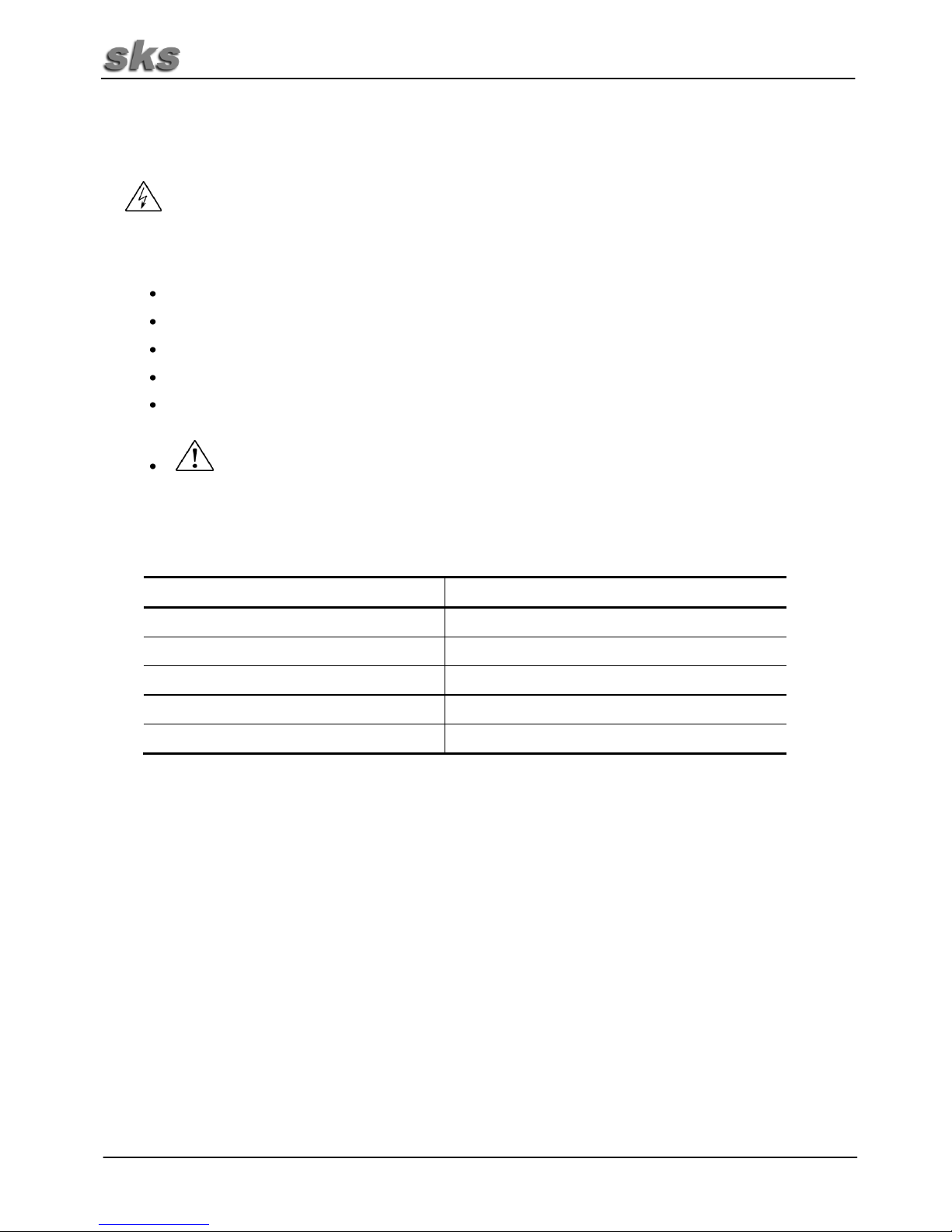
3. Assembly Instructions FS4510
Using a screwdriver carefully push the lower clip in
and remove the entire front.
Assembly of Mounting Box:
Fasten the rear part of the intercom unit to the wall
using dowels and screws to the wall. Watch the cable!
Connect the cable to the connection terminal.
Carefully unplug the red plug connector.
Page 13

~ 13 ~
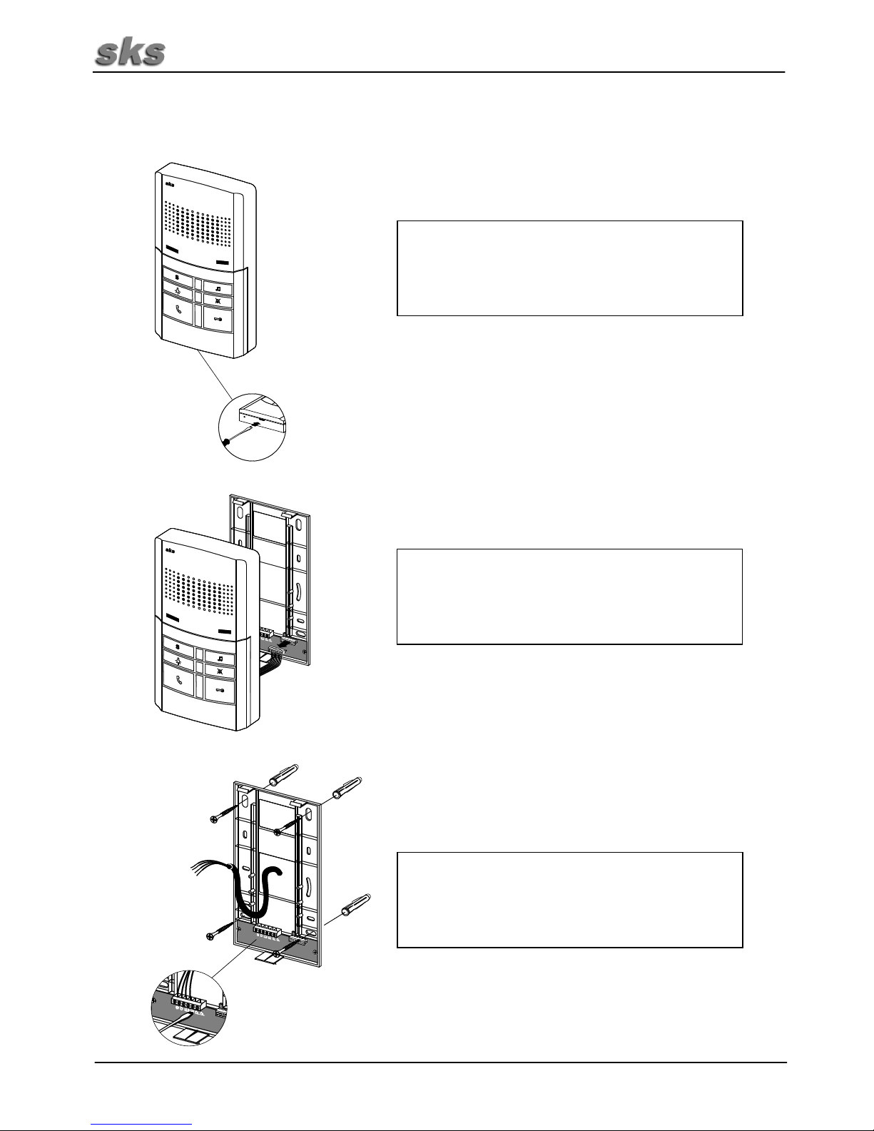
Assembly Instructions FS4510 (Continued)
Flush Mounting Socket Assembly:
Using two screws, fasten the rear part of the intercom
to the flush-mounting socket. Watch the cable!
Connect the cable to the connection terminal.
Plug the red plug connector back in. Watch the
polarity. Then, press the front piece onto the rear piece
until the clips snap into place. Make sure that no
exposed wires can touch the printed circuit board from
behind.
Page 14

~ 14 ~
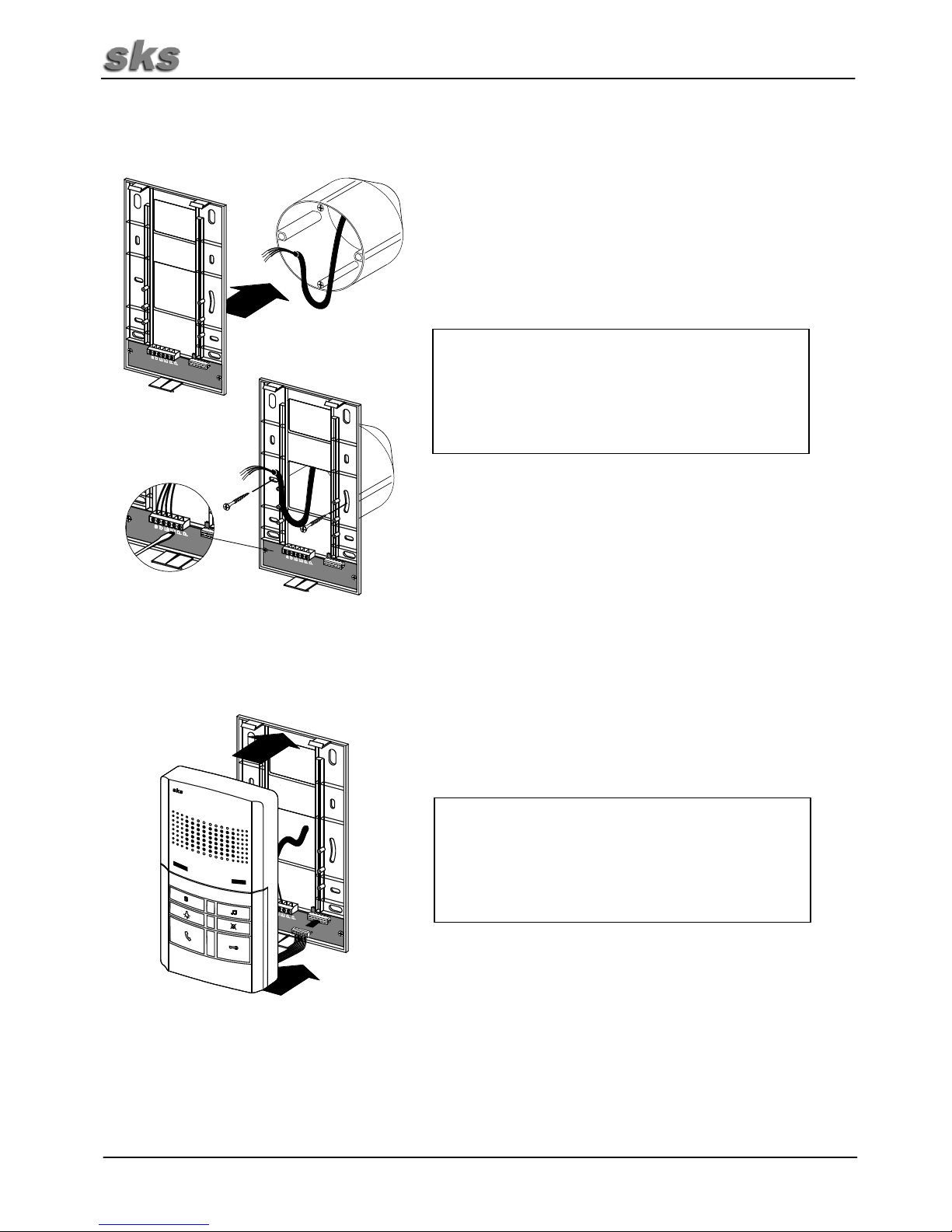
Assembly Instructions FS4510 (Continued)
Set the SKS-BUS call address on the intercom unit.
Each address is assigned to one bell button at the
door station. The addresses are listed n the appendix.
Normally, the SKS-BUS call address will set in with
“A1“.
When replacing intercom units set the DIP-Switch as
for the previously mounted intercom unit.
Loosen the keypad cover with a screwdriver.
Press the keypad cover again onto the intercom unit
until the clips snap into place.
Page 15

~ 15 ~
4. Programming
4.1 Programming Only One Call Address (One Call Button for One Intercom Unit)
Set the desired call address for the device on the DIP-Switch following the SKS-Bus Address Table in
the appendix. Each call address is assigned to one bell button in the door station. The call address
distribution is stored in the door station or in the door speaker 4503, 4508 or 4808.
4.2 Programming up to 4 Call Addresses
(2...4 Bell Buttons for an Intercom Unit or Internal Call Units)
The intercom unit can store up to 4 SKS-BUS call addresses for house call, internal call or group call
addresses. The first address is the main address and is transmitted as the device identification. The
intercom unit will respond to up to 3 additional call addresses for incoming house calls (bell button for
the door station), internal calls (talking between two intercom units) and group calls (talking between
one intercom unit and up to 4 other intercom units).
Step
Description
1
Set the call address on the DIP-Switch. The 1st call address is the house call
(bell button on the door station).
2
Push the programming button for about 5 seconds until you hear the control
tone.
3
After this control tone sounds you will hear a short tone that signals that the
first call address has been programmed. The number of short tones indicates
the memory location at which the call address was stored.
4
To program additional call addresses, repeat steps 1 to 3. A maximum of 4 call
addresses can be stored. If call addresses need to be changed, all call
addresses must first be deleted, as described under 4.3.
Note:
After programming is finished, set the DIP-Switch to the main address again so that it is possible
to assign the button to the intercom in the case of a fault.
4.3 Delete All Call Addresses
Call addresses cannot be deleted individually. All addresses are deleted every time. Hold the
programming button down for around 25 seconds. While you are doing this, you will hear several control
tones. Deletion is completed when you hear a 3-second-long high-pitched signal tone. Now release the
programming button. All call addresses have been deleted.
Note:
After you have deleted the programmed call addresses, only the address set on the DIP-Switch
is in effect, as described under 4.1.
For special function
only
DIP switch programming key
Page 16

~ 16 ~
5. Setting Up Internal Calling
5.1 Programming Internal Call Addresses
Internal calling makes it possible to call between two intercom units. Using the FS4510, you can
communicate with up to 2 intercom units. The light and special buttons on the FS4510 are provided for
this purpose. Press the corresponding button to place an internal call.
Note:
The function “Internal Call” is only possible with special models. If you need this function, let us know when
you place your order.
Intercom Unit
Internal Call Button(s)
A
B
Programming Procedure for Internal Addresses:
Note:
Before the internal call addresses can be programmed, the house call address must be
programmed as described in 4.2.
Step
Description
1
Set the internal call address (target address) on the DIP-Switch.
2
Push the talk button until you hear the signal tone.
3
Push the programming button and the desired internal call button (light or
special button) for the desired intercom unit. Push these buttons for around 5
seconds until you hear the second signal tone.
5.2 Deleting Internal Call Addresses
No individual internal call addresses can be deleted. When you delete, all internal call addresses stored
will always be deleted.
Push the programming button down and the corresponding internal call button within 2 seconds. Deletion
is completed when you hear a high-pitched tone lasting 3 seconds. Release the buttons. Now all call
addresses are deleted.
Page 17

~ 17 ~
6. Operating Instructions
Function
Button
Procedure
Accept call
Push the talk button after the unit has been rung.
Two-way communication
Once a call is accepted, you can use the talk button to deactivate hands-free
speaking. As long as the talk button is pushed you can speak from the
intercom to the door station. By not pushing the button it is just possible to
communicate from the door station to the intercom. Two-way communication
is only active for the duration of the call.
Silent mode
Push the silent key (for about 5 seconds) until you hear the confirmation tone
(3 tones of equal length). Now the ringer is deactivated. To indicate this
status, a red LED will blink once every second.
The ringer will be turned on again automatically after 12 hours or
after a power outage.
Turn ringer on
Push the silent mode button once. You will hear a continuous, high-pitched
signal tone. The ringer is now activated again.
Open door
If the device is rung, the door can be opened within 2.5 minutes using the
open door button.
Change house call tune
+
Push the sound button and then quickly press the open door button within 2
seconds. A different tune will sound with each push of the button. When the
desired tune plays, release both buttons. 8 different buttons are available.
Change floor call tune
+
Push the sound button and then quickly press the open door button within 2
seconds. A different tune will sound with each push of the button. Wait until
the desired tune plays, then release both buttons.
There are 4 different floor call tunes.
Change ring volume
Push the sound button until the desired volume is reached. There are five
different sound settings to select from.
Light and special button
+
Only on the HT4500-4. The special button “S” is used standard for switching
in combination with a switching actuator 4507. Furthermore, pushing the light
button closes an internal potential-free contact at the intercom unit. The light
button can be used optionally to switch the switching actuator. Please
indicate if you want to use this option when ordering.
Internal Call
+
The function “Internal Call” is only available on special models. If you need
this function, please inform us when placing your order.
Up to 2 call addresses are possible. The light button and the special button
can be configured for this function. A button configured for internal calling
cannot be configured for switching with the switching actuator.
Push the talk button and release it and then push and hold the button
configured for internal calling until the confirmation tone is emitted.
Page 18

~ 18 ~
7. Technical Data
Electrical Data
Voltage / b
19 – 23VDC
General
Ambient temperature
-10°C to +45°C
Humidity
20% to 90% non-condensing
Housing
Plastic housing
Dimensions (width x height x depth)
80 x 150 x 25mm
Page 19

~ 19 ~
Page 20

~ 20 ~
1. Installation
Danger d'électrocution pour les personnes. Risque de brûlure, de dommages à l’appareil et de
dysfonctionnements. Les directives de la VDE 0100 et de la VDE 0800 doivent être respectées lors
de l’installation. (Allemagne)
Contre-mesures :
Mettez hors tension toutes les lignes conductrices au début des travaux.
Sécurisez les lignes déconnectées de manière à empêcher toute remise sous tension accidentelle.
Constatez l’absence de tension en procédant à une mesure.
Recouvrez les éléments voisins sous tension ou conducteurs.
Tous les travaux et les connexions électriques doivent répondre aux dispositions nationales du pays
concerné et sont l’affaire de spécialistes dûment qualifiés.
La norme DIN VDE 0100 est à observer et respecter pour les appareils connectés en 230 V.
2. Désignation des bornes
Borne
Désignation
a
Borne de bus
b
Borne de bus
E+
Sonnerie d’étage
E-
Sonnerie d’étage
P
Contact sans potentiel
Page 21

~ 21 ~
3. Instructions de montage FS4510
Enfoncer prudemment le clip en bas au milieu à l’aide
d’un tournevis et démonter intégralement la façade..
Montage apparent :
Fixer au mur la partie arrière du poste avec des vis et
des chevilles. Attention au câble ! Connectez le câble
à la borne de raccordemente.
Détachez prudemment le connecteur rouge.
Page 22

~ 22 ~
Instructions de montage FS4510 (suite)
Montage encastré :
Fixer la partie arrière avec deux vis sur la boîte
d'encastrement. Attention au câble ! Connectez le
câble à la borne de raccordement.
Revissez le connecteur rouge Prenez garde à la
polarité. Appuyez la façade sur la partie arrière jusqu’à
encliquement des clips. Veillez à ce qu’aucun fil nu ne
puisse entrer en contact à l’arrière du circuit imprimé.
Page 23

~ 23 ~
Instructions de montage FS4510 (suite)
Définissez l’adresse d’appel du bus SKS sur le poste.
Chaque adresse est dédiée à une touche de sonnerie
sur la station de porte. Les adresses figurent en
annexe. En règle générale, on commence par
l’adresse d’appel du bus SKS « A1 ».
Lorsque vous remplacez les postes, réglez les
microinterrupteurs DIP comme sur le poste
préalablement monté.
Desserrez la couverture de touches avec un tournevis
Enfoncez la couverture des touches sur le poste
jusqu’à l’encliquètement des clips.
Page 24

~ 24 ~
4. Programmation
4.1 Programmation d’une seule adresse d’appel (un bouton de sonnette pour un carillon sur bus)
D’après le tableau des adresses d’appel du bus SKS situés den annexe, définir l'adresse d'appel de
l’appareil sur l'interrupteur DIP. Chaque adresse d’appel est dédiée de manière fixe à un bouton de
sonnerie dans la station de porte. La répartition des adresses d'appel est enregistrée sur les stations de
porte SKS ou sur le haut parleur 4503 pou 4508 ou 4808.
4.2 Programmation de 4 adresses d’appel au total
(2...4 Bouton de sonnette pour un poste ou la communication interne)
Le poste d’interphone bus peut enregistrer jusqu’à 4 adresses d'appel SKS-BUS pour les adresses
d’appel extérieures, internes ou les adresses d’appel de groupe. La première adresse est alors
l'adresse principale transmise comme identification de matériel interne. Le poste d’interphone réagit aux
3 autres adresses d'appel pour les postes entrants (boutons de sonnette de la station de porte), appels
internes (conversation entre deux postes internes) et appel de groupe (voix d’un poste de groupe
(conserver depuis un poste interne avec l'un des quatre postes internes au total)
Phase de
travail
Description
1
Définir l’adresse d’appel sur l'interrupteur DIP La 1
ère
adresse est le poste
(touche de sonnerie sur la station de porte).
2
Appuyer environ 5 secondes sur le bouton de programmation jusqu’à ce que la
tonalité de contrôle retentisse.
3
Après cette tonalité de contrôle, une brève tonalité signale que la première
adresse d’appel est programmée.
Le nombre de brèves tonalités signale sur quel emplacement de mémoire
l’adresse d'appel a été enregistrée.
4
Répétez les étapes de 1 à 3 pour programmer d’autres adresses d’appel. Il est
possible de mémoriser un maximum de 4 adresses d’appel. Si les adresses
d’appel sont modifiées, il faut d'abord supprimer toutes les adresses d'appel
comme décrit sous 4.3.
Remarque :
Après la fin de la programmation, paramétrer de nouveau l'interrupteur DIP sur l’adresse
principale afin de permettre une attribution plus simple du bouton de touche de sonnerie au poste
en cas de défaut.
4.3 Supprimer toutes les adresses d’appel.
Il est impossible de supprimer des adresses d’appels individuelles. Toutes ces adresses doivent être
supprimées. Maintenez enfoncée la touche programme pendant environ 25 secondes. Plusieurs
tonalités de contrôle retentissent pendant cette opération. La suppression s’achève lorsqu’une longue
tonalité de signalisation aiguë de 3 secondes retentit. Relâchez à présent la touche programme. Toutes
des adresses d’appel sont désormais supprimées.
Remarque :
Après la suppression des adresses d’appel programmées, seule l’adresse définie sur
l’interrupteur DIP est active comme décrit sous le point 4.1.
Seulement pour
fonction spéciales
Touche programmation
Micro interrupteur DIP
Page 25

~ 25 ~
5. Configuration de l'appel interne
5.1 Programmation des adresses d’appel interne
En conversation interne, il est possible de parler entre deux postes intérieurs. Le FS4510 permet de
converser avec 2 postes internes (maxi). La touche éclairage et la touche spéciale sont prévues sur le
FS4510. L’appel interne est lancé en appuyant sur la touche requise.
Remarque :
La fonction « Appel interne » est seulement possible sur un modèle spécial ; si vous avez besoin de cette
fonction, veuillez nous en faire part à la commande.
Poste interne
Touche(s) de conversation interne
A
B
Déroulement de la programmation des adresses d’appel interne
Remarque :
Avant de pouvoir programmer les adresses d’appel interne, l’adresse d’appel extérieur doit être
programmé comme décrit point 4.2.
Phase de
travail
Description
1
Définir l’adresse d’appel interne (adresse de destination) sur l'interrupteur DIP.
2
Maintenez la touche conversation appuyée jusqu’à ce que vous entendiez la
tonalité de contrôle
3
Maintenez la touche conversation enfoncée et appuyez la touche de
conversation interne voulue (touche éclairage ou spéciale) dans un délai de 2
secondes pour le poste interne voulu. Maintenez la combinaison de touches
appuyée pendant environ 5 secondes jusqu’à ce que vous entendiez la
deuxième tonalité de signalisation.
5.2 Suppression des adresses d’appel interne.
Il est impossible de supprimer des adresses d’appel internes individuelles. Toutes les adresses
enregistrées sont toujours effacées lors de suppression.
Maintenez la touche programme appuyée et validez la touche de conversation interne dans un délai de
2 secondes.. La suppression s’achève lorsqu’une tonalité de signalisation de 3 secondes retentit.
Relâchez à présent les touches. Toutes des adresses d’appel sont désormais supprimées.
Page 26

~ 26 ~
6. Mode d'emploi
Fonction
Touches
Procédure à suivre
Accueillir l’appel
Actionner la touche conversation après sonnerie sur l'appareil.
Communication simplex
En prenant l’appel, il est possible de désactiver la fonction main libre avec la
touche conversation. Tant que celle-ci est achevée, la conversation est
possible du poste interne avec la station de porte. Si la touche de conversation
n’est pas actionnée, le sens de la communication va de la station de porte vers
le poste interne. La fonction communication simplex n’est active que pendant la
durée de la conversation.
Fonction « Silence »
Maintenez appuyée la touche "silence“ (env. 5 secondes) jusqu’à ce que vous
entendiez les tonalités de confirmation (3 tonalités de même longueur). La
tonalité d’appel est désactivée. Pour rappeler cet état, la LED rouge clignote
une fois toutes les secondes.
La tonalité d’appel est rétablie automatiquement au bout de 12 heures
ou après une panne secteur.
Activation d’appel
Tapez brièvement sur la touche silence. Vous entendez une forte tonalité de
signalisation continue. La tonalité d’appel est de nouveau activée.
Ouvrir la porte
Si l'appareil sonne, il est possible d'ouvrir la porte en l’espace de 2,5 minutes à
l’aide de la gâche d'ouverture.
Changer la tonalité de
sonnerie extérieure
+
Maintenez appuyée la touche son puis appuyez brièvement pendant 2
secondes la gâche d’ouverture de porte. Une sonnerie différente retentit à
chaque pression de touche. Une fois la mélodie souhaitée exécutée, relâchez
les deux touches.
On peut choisir entre 8 tonalités de sonneries
Changer la tonalité
d’appel à l’étage
+
Maintenez appuyée la touche son puis appuyez brièvement pendant 2
secondes la gâche d’ouverture de porte.et maintenez enfoncée. Attendez
jusqu’à ce que la mélodie souhaitée retentisse. Relâchez les deux touches.
On peut choisir entre 4 tonalités de sonneries à l'étage.
Changer le volume de la
sonnerie
Maintenir appuyée la touche son jusqu’à ce que le volume voulu soit obtenu.
Le volume a 5 positions de réglage.
Touche éclairage et
spéciale
+
La touche „S“ est utilisée par défaut pour la commutation à l’aide d’un
actionneur 4507/ De plus, un contact sans potentiel interne est fermé sur le
poste en actionnant la touche éclairage.
La touche éclairage peut être utilisée en option pour commuter l'actionneur.
Veuillez préciser si vous le souhaitez à la commande.
Appel interne
+
La fonction « Appel interne » est seulement possible sur un modèle spécial ; si
vous avez besoin de cette fonction, veuillez nous en faire part à la commande.
Au total, 2 adresses d’appel sont possibles. La touche éclairage mais aussi la
touche spéciale peuvent être configurées pour cette fonction. Une touche
configurée pour l’appel interne ne peut plus utilisée pour une commutation avec
l’actionneur.
Pressez puis relâchez la touche conversation puis maintenez la touche
configurée pour l’appel interne jusqu’à ce que la tonalité de confirmation soit
émise.
Station de porte Station de porte
Page 27

~ 27 ~
7. Caractéristiques techniques
Caractéristiques électriques
Tension a / b
19 – 23VDC
Généralités
Température ambiante
de -10°C à +45°C
Humidité
20% à 90% sans condensation
Boîtier
Boîtier plastique
Dimensions (largeur x hauteur x profondeur)
80 x 150 x 25mm
Page 28

~ 28 ~
Page 29

~ 29 ~
Anhang, Appendix, Annexe
DIP-Switch settings for intercoms, switch actuator and TK-Adapter
Standard address range Extended address range
 Loading...