

Page 1
Installationsanleitung
Installation instructions
SKS-Kinkel Elektronik GmbH
Version: 1.1
Support-Hotline: +49 (0) 2661 98088 112
E-Mail: support@sks-kinkel.de Dokument Art. Nr. 97011101
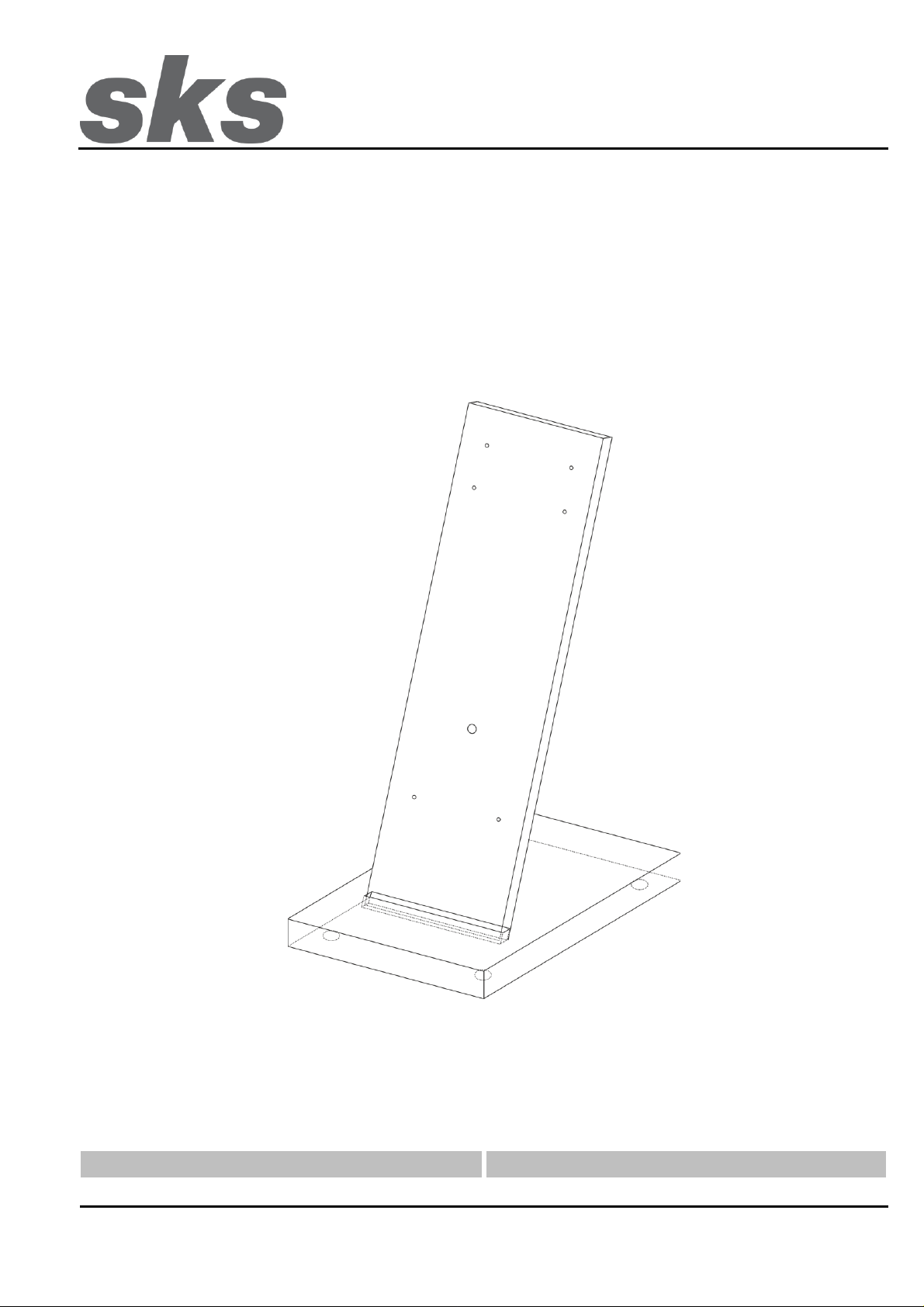
300101 Tischmontageset
Für Innensprechstellen:
DS2010 Video Hörer
HTV4600
Page 2

SKS-Kinkel Elektronik GmbH
DE
300101 Tischmontageset
Support-Hotline: +49 (0) 2661 98088 112
- 2 -
Version: 1.1
E-Mail: support@sks-kinkel.de Dokument Art. Nr. 97011101
Inhaltsverzeichnis
1 Installation ........................................................................................................................................................... 3
2 Klemmenbezeichnung ........................................................................................................................................ 3
3 Montage ............................................................................................................................................................... 4
3.1 DS2010 Video Hörer .................................................................................................................................... 4
3.1.1 Vorbereitung ............................................................................................................................................. 4
3.1.2 Befestigung .............................................................................................................................................. 6
3.1.3 Demontage ............................................................................................................................................... 7
3.2 HTV4600 ...................................................................................................................................................... 8
3.2.1 Vorbereitung ............................................................................................................................................. 8
3.2.2 Befestigung ............................................................................................................................................ 10
3.2.3 Demontage ............................................................................................................................................. 11
4 Struktur- und Verdrahtungsplan ..................................................................................................................... 12
5 Service ............................................................................................................................................................... 13
Index
1 Installation ......................................................................................................................................................... 14
2 Terminal designation ........................................................................................................................................ 14
3 Mounting instructions ...................................................................................................................................... 15
3.1 DS2010 Video reciever .............................................................................................................................. 15
3.1.1 Preparation ............................................................................................................................................. 15
3.1.2 Mounting ................................................................................................................................................ 17
3.1.3 Disassembly ........................................................................................................................................... 18
3.2 HTV4600 .................................................................................................................................................... 19
3.2.1 Preparation ............................................................................................................................................. 19
3.2.2 Mounting ................................................................................................................................................ 21
3.2.3 Disassembly ........................................................................................................................................... 22
4 Structure and wiring plan ................................................................................................................................ 23
5 Service ............................................................................................................................................................... 24
Page 3
SKS-Kinkel Elektronik GmbH
DE
300101 Tischmontageset
Support-Hotline: +49 (0) 2661 98088 112
- 3 -
Version: 1.1
E-Mail: support@sks-kinkel.de Dokument Art. Nr. 97011101
1 Installation
Gefahr für Personen durch einen elektrischen Schlag, Verbrennungsgefahr, Geräteschäden und
Fehlfunktionen. Bei der Installation sind die Richtlinien der VDE 0100 und VDE 0800 einzuhalten.
(Deutschland)
Gegenmaßnahmen:
Schalten Sie zu Beginn der Arbeiten alle spannungsführenden Leitungen frei.
Sichern Sie die ausgeschalteten Leitungen gegen irrtümliches Wiedereinschalten.
Stellen Sie Spannungsfreiheit durch Messung fest.
Decken Sie benachbarte, unter Spannung stehende, oder leitfähige Teile ab.
Alle Arbeiten und elektrische Anschlüsse müssen den nationalen Bestimmungen des jeweiligen Landes
entsprechen und von entsprechend ausgebildetem Fachpersonal durchgeführt werden.
Bei Geräten mit 230-V-Anschluss ist die DIN VDE 0100 zu beachten und einzuhalten.
2 Klemmenbezeichnung
Klemme
Bezeichnung
a+ / b-
Bus-Klemmen
E+ / E-
Etagentaster
V+ / V-
Videosignal
+22 / GND
Versorgungsspannung
Page 4
SKS-Kinkel Elektronik GmbH
DE
300101 Tischmontageset
Support-Hotline: +49 (0) 2661 98088 112
- 4 -
Version: 1.1
E-Mail: support@sks-kinkel.de Dokument Art. Nr. 97011101
3 Montage
Jedem Tischmontageset ist eine Anschlussdose und ein Cat-Anschlusskabel beigelegt. Die Anschlussdose wird
nach dem Verdrahtungsplan angeschlossen (Punkt 5). Die Verbindung zwischen Anschlussdose und
Tischmontageset erfolgt durch das mitgelieferte Cat-Anschlusskabel.
3.1 DS2010 Video Hörer
3.1.1 Vorbereitung
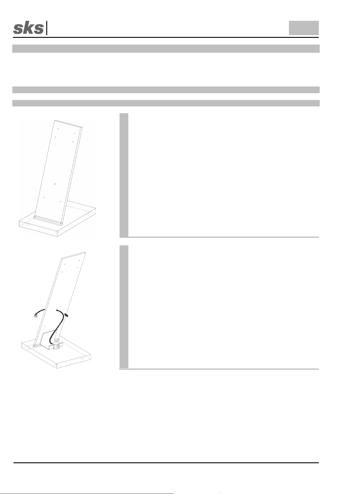
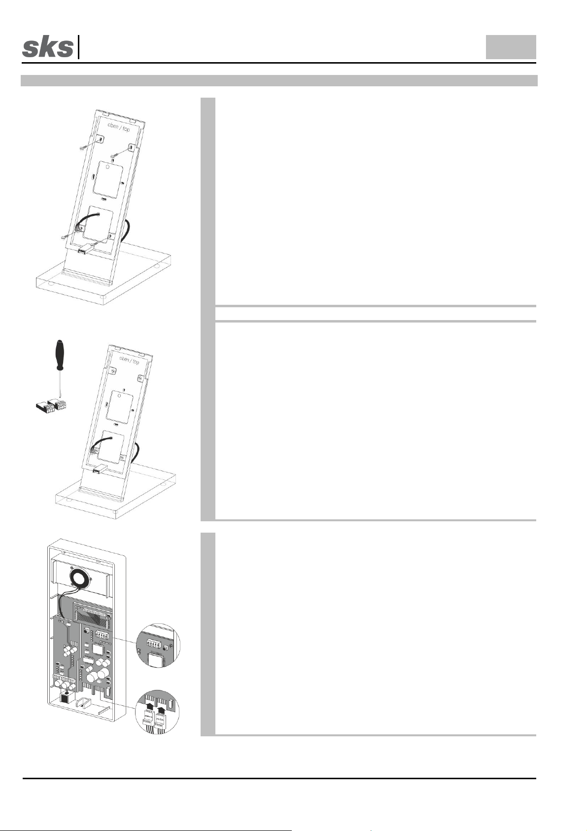
Entnehmen Sie das Tischmontageset aus der Verpackung und stellen
Sie es auf. Das Tischmontageset wird komplett vorbereitet ausgeliefert
und muss nicht zusammengebaut werden.
Auf der Rückseite des Tischmontagesets befindet sich der
Anschlussadapter.
Stecken Sie das Anschlussadapterkabel, wie auf der Zeichnung zu
sehen, durch die dafür vorgesehene Öffnung im Tischmontageset.
Page 5
SKS-Kinkel Elektronik GmbH
DE
300101 Tischmontageset
Support-Hotline: +49 (0) 2661 98088 112
- 5 -
Version: 1.1
E-Mail: support@sks-kinkel.de Dokument Art. Nr. 97011101
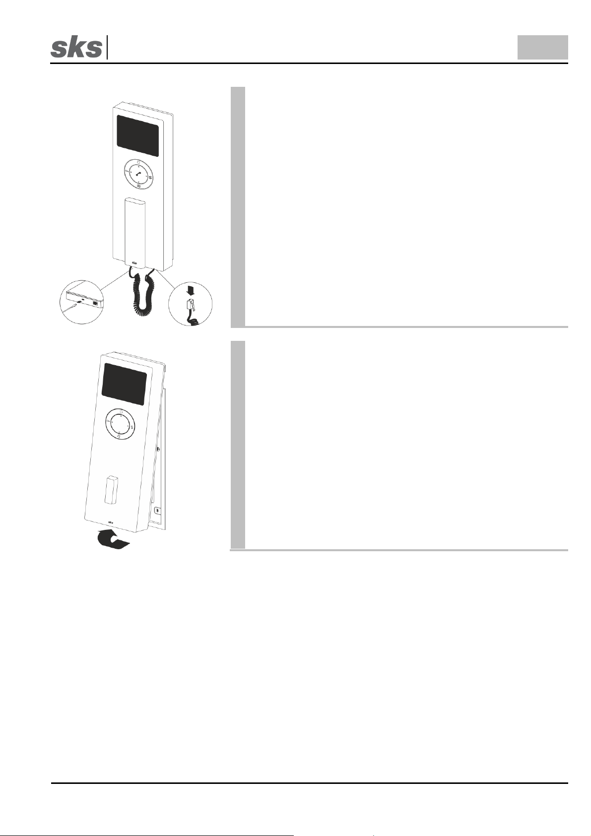
Lösen Sie die Innensprechstelle von dem Geräteträger, indem Sie mit
dem Schraubendreher in die Entriegelungsöffnung auf der Unterseite
der Innensprechstelle hineindrücken.
Nehmen Sie vorsichtig die Innensprechstelle, wie auf der Zeichnung
zu sehen, von dem Geräteträger ab.
Ziehen Sie die Unterseite der Innensprechstelle zu sich hin und heben
Sie dann diese nach oben hin ab.
Page 6
SKS-Kinkel Elektronik GmbH
DE
300101 Tischmontageset
Support-Hotline: +49 (0) 2661 98088 112
- 6 -
Version: 1.1
E-Mail: support@sks-kinkel.de Dokument Art. Nr. 97011101
3.1.2 Befestigung
Montieren Sie den Geräteträger anschließend mit den mitgelieferten
Schrauben an dem Tischmontageset. Benutzen Sie dazu die
Befestigungslöcher im oberen und unteren Bereich des Geräteträgers.
Achten Sie bei der Befestigung des Geräteträgers auf das
Installationskabel!
Schließen Sie die Anschlussklemmen an das Anschlussadapterkabel
an. Die Anschlussklemmen finden Sie auf der Rückseite der
Innensprechstelle.
Um Fehler bei dem Anschluss zu vermeiden, nehmen Sie die
Planungshilfe und den Verdrahtungsplan zu Hilfe. Beim
Austausch der Innensprechstelle ist unbedingt auf die
Einstellung des DIP-Schalters zu achten.
Stecken Sie die Anschlussklemmen auf die Rückseite der
Innensprechstelle auf und stellen Sie die SKS-Bus Rufadresse an
dem DIP-Schalter auf der Rückseite der Innensprechstelle ein. Jede
Adresse ist einem Klingeltaster an der Türstation zugeordnet. Die
SKS-Bus Rufadressentabelle befindet sich im Anhang.
Page 7
SKS-Kinkel Elektronik GmbH
DE
300101 Tischmontageset
Support-Hotline: +49 (0) 2661 98088 112
- 7 -
Version: 1.1
E-Mail: support@sks-kinkel.de Dokument Art. Nr. 97011101
Hängen Sie als nächstes die Innensprechstelle im oberen Bereich des
Geräteträgers ein.
Drücken Sie anschließend die Innensprechstelle auf den
Geräteträger, bis diese hörbar einrastet.
3.1.3 Demontage
Lösen Sie die Innensprechstelle von dem Geräteträger, indem Sie mit
dem Schraubendreher in die Entriegelungsöffnung auf der Unterseite
der Innensprechstelle hineindrücken.
Nehmen Sie vorsichtig die Innensprechstelle, wie auf der Zeichnung
zu sehen, von dem Geräteträger ab.
Ziehen Sie die Unterseite der Innensprechstelle zu sich hin und heben
Sie dann diese nach oben hin ab.
Page 8
SKS-Kinkel Elektronik GmbH
DE
300101 Tischmontageset
Support-Hotline: +49 (0) 2661 98088 112
- 8 -
Version: 1.1
E-Mail: support@sks-kinkel.de Dokument Art. Nr. 97011101
3.2 HTV4600
3.2.1 Vorbereitung
Entnehmen Sie das Tischmontageset aus der Verpackung und stellen
Sie es auf. Das Tischmontageset wird komplett vorbereitet ausgeliefert
und muss nicht zusammengebaut werden.
Auf der Rückseite des Tischmontagesets befindet sich der
Anschlussadapter.
Stecken Sie das Anschlussadapterkabel, wie auf der Zeichnung zu
sehen, durch die dafür vorgesehene Öffnung im Tischmontageset.
Page 9

SKS-Kinkel Elektronik GmbH
DE
300101 Tischmontageset
Support-Hotline: +49 (0) 2661 98088 112
- 9 -
Version: 1.1
E-Mail: support@sks-kinkel.de Dokument Art. Nr. 97011101
Lösen Sie die Innensprechstelle von dem Geräteträger, indem Sie mit
dem Schraubendreher in die Entriegelungsöffnung auf der Unterseite
der Innensprechstelle hineindrücken.
Nehmen Sie vorsichtig die Innensprechstelle, wie auf der Zeichnung
zu sehen, von dem Geräteträger ab.
Ziehen Sie die Unterseite der Innensprechstelle zu sich hin und heben
Sie dann diese nach oben hin ab.
Page 10

SKS-Kinkel Elektronik GmbH
DE
300101 Tischmontageset
Support-Hotline: +49 (0) 2661 98088 112
- 10 -
Version: 1.1
E-Mail: support@sks-kinkel.de Dokument Art. Nr. 97011101
3.2.2 Befestigung
Montieren Sie den Geräteträger anschließend mit den
mitgelieferten Schrauben an dem Tischmontageset. Benutzen Sie
dazu die Befestigungslöcher im oberen und unteren Bereich des
Geräteträgers.
Achten Sie bei der Befestigung des Geräteträgers auf das
Installationskabel!
Schließen Sie die Anschlussklemmen an das
Anschlussadapterkabel an. Die Anschlussklemmen finden Sie auf
der Rückseite der Innensprechstelle.
Um Fehler bei dem Anschluss zu vermeiden, nehmen Sie die
Planungshilfe und den Verdrahtungsplan zu Hilfe. Beim
Austausch der Innensprechstelle ist unbedingt auf die
Einstellung des DIP-Schalters zu achten.
Stecken Sie die Anschlussklemmen auf die Rückseite der
Innensprechstelle auf und stellen Sie die SKS-Bus Rufadresse an
dem DIP-Schalter auf der Rückseite der Innensprechstelle ein.
Jede Adresse ist einem Klingeltaster an der Türstation zugeordnet.
Die SKS-Bus Rufadressentabelle befindet sich im Anhang.
Page 11

SKS-Kinkel Elektronik GmbH
DE
300101 Tischmontageset
Support-Hotline: +49 (0) 2661 98088 112
- 11 -
Version: 1.1
E-Mail: support@sks-kinkel.de Dokument Art. Nr. 97011101
Hängen Sie als nächstes die Innensprechstelle im oberen Bereich des
Geräteträgers ein.
Drücken Sie anschließend die Innensprechstelle auf den Geräteträger
bis diese hörbar einrastet.
3.2.3 Demontage
Lösen Sie die Innensprechstelle von dem Geräteträger, indem Sie mit
dem Schraubendreher in die Entriegelungsöffnung auf der Unterseite
der Innensprechstelle hineindrücken.
Nehmen Sie vorsichtig die Innensprechstelle, wie auf der Zeichnung
zu sehen, von dem Geräteträger ab.
Ziehen Sie die Unterseite der Innensprechstelle zu sich hin und heben
Sie dann diese nach oben hin ab.
Page 12

SKS-Kinkel Elektronik GmbH
DE
300101 Tischmontageset
Support-Hotline: +49 (0) 2661 98088 112
- 12 -
Version: 1.1
E-Mail: support@sks-kinkel.de Dokument Art. Nr. 97011101
4 Struktur- und Verdrahtungsplan
Page 13

SKS-Kinkel Elektronik GmbH
DE
300101 Tischmontageset
Support-Hotline: +49 (0) 2661 98088 112
- 13 -
Version: 1.1
E-Mail: support@sks-kinkel.de Dokument Art. Nr. 97011101
5 Service
Für die Gewährleistung gelten die gesetzlichen Bestimmungen (vgl. hierzu auch unsere beigefügten bzw. im Internet unter
www.sks-kinkel.de/agb/ abrufbaren und einsehbaren AGB)
Abwicklung der Gewährleistung
Wir bieten unseren Kunden und auch Elektrofachkräften eine vereinfachte Abwicklung von Gewährleistungsfällen an. Dafür
beachten Sie die Verkaufs- und Lieferbedingungen auf unserer Internetpräsenz oder wenden Sie sich an unsere SKS-Support
Hotline.
Entsorgungshinweise
Durch die separate Sammlung von Elektro- und Elektronikaltgeräten soll die Wiederverwendung, die stoffliche Verwertung bzw.
andere Formen der Verwertung von Altgeräten ermöglicht sowie negative Folgen bei der Entsorgung der in den Geräten
möglicherweise enthaltenen gefährlichen Stoffe auf die Umwelt und die menschliche Gesundheit vermieden werden. Entsorgen
Sie die Verpackungsteile getrennt in Sammelbehältern für Pappe und Papier bzw. Kunststoff.
Die Produkte entsprechen den gesetzlichen Anforderungen, insbesondere dem Elektro- und Elektronikgerätegesetz und der
REACH-Verordnung. (EU-Richtlinie 2012/19/EU WEEE und 2011/65/EU RoHS, EU-REACH-Verordnung und Gesetz zu
Durchführung der Verordnung (EG) Nr.1907/2006).
Pflegehinweise
Reinigen Sie das Gerät nur mit einem weichen Tuch, welches mit einer milden Seifenlösung angefeuchtet ist. Trockene
Reinigung, aggressive Reiniger und Scheuermittel können die Oberfläche beschädigen.
Haftungsausschluss
Wir haben den Inhalt der Druckschrift auf Übereinstimmung mit der beschriebenen Hard- und Software geprüft. Es können
dennoch Abweichungen nicht ausgeschlossen werden, so dass wir für die vollständige Übereinstimmung keine Gewähr
übernehmen. Die Angaben dieser Druckschrift werden regelmäßig überprüft und notwendige Korrekturen sind in den
nachfolgenden Auflagen enthalten.
Service und Support
Unser Supportteam steht Ihnen mit Rat und Tat zur Seite und kümmert sich um Ihre Anliegen. Unser SKS-Support ist für Sie per
E-Mail und Telefon erreichbar. Bitte geben Sie stets eine möglichst genaue Fehlerbeschreibung, Projektbezeichnung, Ihren
Namen und Ihre Kundennummer mit an.
Folgende Möglichkeiten stehen Ihnen zur Verfügung:
SKS-Support Hotline
+49 (0) 2661 98088 112
SKS-Support E-Mail
support@sks-kinkel.de
Wir bieten ausschließlich Support für das Elektro-Handwerk, Architekten und Planungsbüros – Endkunden wenden sich bitte an
Ihren Elektro-Handwerksbetrieb
Anschrift
SKS-Kinkel Elektronik GmbH, Im Industriegebiet 9, 56472 Hof/ Westerwald
Tel.: +49 (0) 2661 980 88 0, Fax: +49 (0) 2661 980 88 200
E-Mail: info@sks-kinkel.de, www.sks-kinkel.de
Entsorgen Sie das Gerät nicht in den Hausmüll, sondern über eine Sammelstelle für Elektronikschrott. Die
zuständige Sammelstelle erfragen Sie bitte bei Ihrer Stadt- bzw. Kommunalverwaltung.
Page 14

SKS-Kinkel Elektronik GmbH
EN
300101 Table installation kit
Support-Hotline: +49 (0) 2661 98088 112
- 14 -
Version: 1.1
E-Mail: support@sks-kinkel.de Document art. no. 97011101
300101 Table installation kit
For indoor station:
DS2010 Video reciever
HTV4600
1 Installation
Electrical shock hazard to persons. Danger of burns, damage to device and malfunctions. Observe VDE 0100
and VDE 0800 guidelines during installation. (Germany)
Counter measures:
Before beginning any work, deactivate and disconnect all energized electrical wires.
Secure the switched off/ disconnected lines against erroneous reconnection.
Use a measuring device to make sure that the wires are de energized.
Cover up any adjacent, energized or conducting components.
All work and all electrical connections must comply with the national provisions for the country in question
and must be performed by appropriately trained personnel.
DIN VDE 0100 must be observed and complied with in devices with a 230V connection.
2 Terminal designation
Terminal
Designation
a+ / b-
Bus-terminal
E+ / E-
Floor bell
V+ / V-
Videosignal
+22 / GND
Power supply
Page 15

SKS-Kinkel Elektronik GmbH
EN
300101 Table installation kit
Support-Hotline: +49 (0) 2661 98088 112
- 15 -
Version: 1.1
E-Mail: support@sks-kinkel.de Document art. no. 97011101
3 Mounting instructions
Each table installation kit is supplied with a Cat connection socket and a Cat connection cable. To avoid errors when
connecting cables please use the planning guide or the wiring diagram. (Point 5). The connection between the Cat
connection socket and the table installation kit is made by the supplied Cat connection cable.
3.1 DS2010 Video reciever
3.1.1 Preparation
Remove the table installation kit from the packaging and set it up. The
table installation kit delivered completely prepared and does not have
to be assembled.
The connection adapter is located on the back of the table installation
kit.
Plug the adapter cable through the provided opening hole in the table
installation kit as shown in the drawing.
Page 16

SKS-Kinkel Elektronik GmbH
EN
300101 Table installation kit
Support-Hotline: +49 (0) 2661 98088 112
- 16 -
Version: 1.1
E-Mail: support@sks-kinkel.de Document art. no. 97011101
Use a screwdriver to release the indoor station from its supporting
frame. This is done by inserting the screwdriver into the release
opening at the bottom of the indoor station.
Carefully remove the indoor station from the support frame as shown
in the drawing.
Pull the lower part of the indoor station towards you and carefully lift it
upwards.
Page 17

SKS-Kinkel Elektronik GmbH
EN
300101 Table installation kit
Support-Hotline: +49 (0) 2661 98088 112
- 17 -
Version: 1.1
E-Mail: support@sks-kinkel.de Document art. no. 97011101
3.1.2 Mounting
Using the screws attach the supporting frame of the indoor station to
the table installation kit. Please use the fastening holes provided on
the upper and under part on the table installation kit.
Pay particular attention to the installation cable when mounting
the supporting frame!
Connect the terminals to the previously installed cable. The terminals
are located at the back of the indoor station.
The pre-assembled cables are then connected to the indoor station.
To avoid errors when connecting cables please use the planning
guide or the wiring diagram. Pay particular attention to the
setting of the DIP switch when the indoor station is replaced!
Set the SKS bus call address at the DIP switch on the back of the
indoor station. Each address is assigned to a bell button at the door
station. The SKS bus table of call addresses can be found in the
appendix.
Page 18

SKS-Kinkel Elektronik GmbH
EN
300101 Table installation kit
Support-Hotline: +49 (0) 2661 98088 112
- 18 -
Version: 1.1
E-Mail: support@sks-kinkel.de Document art. no. 97011101
Remount the indoor station in the upper part of the supporting frame.
Subsequently press the indoor station onto the frame until it clicks into
place.
3.1.3 Disassembly
Use a screwdriver to release the indoor station from its supporting
frame. This is done by inserting the screwdriver into the release
opening at the bottom of the indoor station.
Carefully remove the indoor station from the support frame as shown
in the drawing.
Pull the lower part of the indoor station towards you and carefully lift it
upwards.
Page 19

SKS-Kinkel Elektronik GmbH
EN
300101 Table installation kit
Support-Hotline: +49 (0) 2661 98088 112
- 19 -
Version: 1.1
E-Mail: support@sks-kinkel.de Document art. no. 97011101
3.2 HTV4600
3.2.1 Preparation
Remove the table installation kit from the packaging and set it up. The
table installation kit delivered completely prepared and does not have
to be assembled.
The connection adapter is located on the back of the table installation
kit.
Plug the adapter cable through the provided opening hole in the table
installation kit as shown in the drawing.
Page 20

SKS-Kinkel Elektronik GmbH
EN
300101 Table installation kit
Support-Hotline: +49 (0) 2661 98088 112
- 20 -
Version: 1.1
E-Mail: support@sks-kinkel.de Document art. no. 97011101
Use a screwdriver to release the indoor station from its supporting
frame. This is done by inserting the screwdriver into the release
opening at the bottom of the indoor station.
Carefully remove the indoor station from the support frame as shown
in the drawing.
Pull the lower part of the indoor station towards you and carefully lift it
upwards.
Page 21

SKS-Kinkel Elektronik GmbH
EN
300101 Table installation kit
Support-Hotline: +49 (0) 2661 98088 112
- 21 -
Version: 1.1
E-Mail: support@sks-kinkel.de Document art. no. 97011101
3.2.2 Mounting
Using the screws attach the supporting frame of the indoor station
to the table installation kit. Please use the fastening holes provided
on the upper and lower part on the table installation kit.
Pay particular attention to the installation cable when
mounting the supporting frame!
Connect the terminals to the previously installed cable. The
terminals are located at the back of the indoor station.
The pre-assembled cables are then connected to the indoor
station.
To avoid errors when connecting cables please use the
planning guide or the wiring diagram. Pay particular attention
to the setting of the DIP switch when the indoor station is
replaced!
Set the SKS bus call address at the DIP switch on the back of the
indoor station. Each address is assigned to a bell button at the
door station. The SKS bus table of call addresses can be found in
the appendix.
Page 22

SKS-Kinkel Elektronik GmbH
EN
300101 Table installation kit
Support-Hotline: +49 (0) 2661 98088 112
- 22 -
Version: 1.1
E-Mail: support@sks-kinkel.de Document art. no. 97011101
Remount the indoor station in the upper part of the supporting frame.
Subsequently press the indoor station onto the frame until it clicks into
place.
3.2.3 Disassembly
Use a screwdriver to release the indoor station from its supporting
frame. This is done by inserting the screwdriver into the release
opening at the bottom of the indoor station.
Carefully remove the indoor station from the support frame as shown
in the drawing.
Pull the lower part of the indoor station towards you and carefully lift it
upwards.
Page 23

SKS-Kinkel Elektronik GmbH
EN
300101 Table installation kit
Support-Hotline: +49 (0) 2661 98088 112
- 23 -
Version: 1.1
E-Mail: support@sks-kinkel.de Document art. no. 97011101
4 Structure and wiring plan
Page 24

SKS-Kinkel Elektronik GmbH
EN
300101 Table installation kit
Support-Hotline: +49 (0) 2661 98088 112
- 24 -
Version: 1.1
E-Mail: support@sks-kinkel.de Document art. no. 97011101
5 Service
Statutory provisions for warranty shall apply. (See general terms and conditions in the appendix or the internet at www.skskinkel.de/agb/).
Warranty
Statutory provisions for warranty shall apply. (See general terms and conditions in the appendix or the internet at www.skskinkel.de/agb/).
Disposal instructions
By separately disposing of electrical and electronic devices you will allow for the reuse, renewing and recycling of materials and
used appliances and equipment. At the same time this separation shall prevent negative effects of the possibly existing
dangerous substances and materials on the environment and public health. Dispose of the packaging in the respective separate
containers for cardboard, paper and plastics.
The products comply with the regulatory requirement, in particular with electrical and electronic equipment act and the REACH-
regulation. (EU- guideline 2012/19/EU WEEE and 2011/65/EU RoHS). EU-REACH- regulation and the law implementing
regulation (EG) Nr.1907/2006).
Liability disclaimer
We have checked the content of this document to verify that it corresponds to the hard- and software described herein. There
may, however, be deviations and SKS-Kinkel GmbH may not be held liable for a lack of conformity. The information in this
document is checked regularly and necessary changes are made in subsequent issues.
Care instructions
Please just clean the device unit with a soft cloth, moistened with a mild soap solution. Dry cleaning, aggressive detergents and
abrasives may damage the surface.
Service and support
Our support team provides practical assistance and advice. SKS support may be reached via email or phone. When contacting
us please provide an exact description of the fault, the project name your name and your customer ID.
We provide the following options:
SKS-Support Hotline
+49 (0) 2661 98088 112
SKS-Support E-Mail
support@sks-kinkel.de
Support is exclusively provided for electricians, architects or planning offices. End customers are asked to contact their
electrician.
Address
SKS-Kinkel Elektronik GmbH, Im Industriegebiet 9, 56472 Hof/ Westerwald
Tel.: +49 (0) 2661 980 88 0, Fax: +49 (0) 2661 980 88 200
E-Mail: info@sks-kinkel.de, www.sks-kinkel.de
Do not dispose of the device with the regular household refuse but take it to a collection point for electronic
scrap. The respective collection point is provided by the municipal administration in the area.
 Loading...