

Page 1
Installationsanleitung
Installation instructions
SKS-Kinkel Elektronik GmbH
Version: 1.3
Support-Hotline: +49 (0) 2661-98088-112
E-Mail:support@sks-kinkel.de
Dokument Art. Nr. 97009603
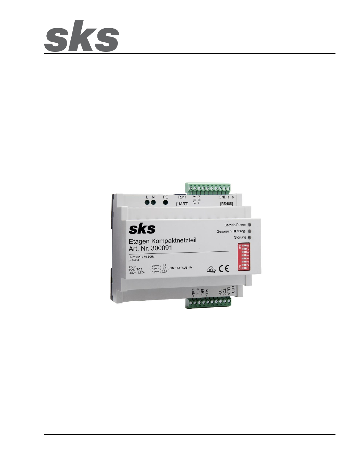
300091 Etagen Kompaktnetzteil
Page 2
SKS-Kinkel Elektronik GmbH
DE
300091 Etagen Kompaktnetzteil
Support-Hotline: +49 (0) 2661-98088-112
- 2 -
Version: 1.3
E-Mail: support@sks-kinkel.de Dokument Art. Nr. 97009603
1 Installation
Gefahr für Personen durch einen elektrischen Schlag, Verbrennungsgefahr, Geräteschäden und
Fehlfunktionen. Bei der Installation sind die Richtlinien der VDE 0100 und VDE 0800 einzuhalten.
(Deutschland)
Gegenmaßnahmen:
• Schalten Sie zu Beginn der Arbeiten alle spannungsführenden Leitungen frei.
• Sichern Sie die ausgeschalteten Leitungen gegen irrtümliches Wiedereinschalten.
• Stellen Sie Spannungsfreiheit durch Messung fest.
• Decken Sie benachbarte, unter Spannung stehende, oder leitfähige Teile ab.
• Alle Arbeiten und elektrische Anschlüsse müssen den nationalen Bestimmungen des jeweiligen Landes
entsprechen und von entsprechend ausgebildetem Fachpersonal durchgeführt werden.
Bei Geräten mit 230-V-Anschluss ist die DIN VDE 0100 zu beachten und einzuhalten.
1.1 Installationsvorschriften und Schutzmaßnahmen
Das Gerät muss so an die Versorgung angeschlossen werden, dass der Benutzer keinen direkten Zugang zum
Bereich der Netzanschlussklemme hat.
Außerhalb des Gerätes muss eine leicht zugängliche Trennvorrichtung vorhanden sein.
Das Gerät entspricht der Überspannungskategorie II.
Außerhalb des Gerätes ist eine Überstrom-Schutzeinrichtung vorzuschalten.
Das Gerät muss über die Klemme PE an das Schutzleitersystem oder den Schutzpotentialausgleich
angeschlossen werden.
Das Gerät entspricht der Schutzart IP20 und muss in der Endanwendung in einem Verteiler oder Gehäuse auf der
Hutschiene montiert sein.
Das Gerät muss in einem Brandschutzgehäuse nach IEC 60950-1 eingebaut werden.
1.2 Warnhinweis
Eindringen von Flüssigkeiten oder elektrisch leitenden Kleinteilen können einen Kurzschluss, Brand oder
elektrischen Schlag verursachen. Das Gerät darf nicht mit Wasser oder anderen Flüssigkeiten in Berührung
gebracht werden.
Vermeiden Sie das Eindringen von elektrisch leitenden Kleinteilen durch die Lüftungsschlitze.
Das Gerät entwickelt im Nennbetrieb Wärme und es ist für eine ausreichende Belüftung zu sorgen. Die
Lüftungsschlitze am Gerät dürfen nicht abgedeckt werden.
Page 3
SKS-Kinkel Elektronik GmbH
DE
300091 Etagen Kompaktnetzteil
Support-Hotline: +49 (0) 2661-98088-112
- 3 -
Version: 1.3
E-Mail: support@sks-kinkel.de Dokument Art. Nr. 97009603
2 Klemmenbezeichnung
Klemme
Bezeichnung
aEL+ / bEL-
Ausgänge a+ / b- Etagenlinie
LED+ / LED-
Ausgang Tableau Beleuchtung
TÖ1 / TÖ2
Ausgang Türöffner
aHL+ / bHL-
Ausgänge a+ / b- Hauptlinie
a / b / GND
RS485 Anschluss
RJ11
Kompakt Interface
L / N / PE
Versorgungsspannung
3 Beschreibung
Eine SKS-Busanlage besteht im einfachsten Fall aus einer Linie, der sogenannten Hauptlinie. Auf der Hauptlinie
kann nur ein Gespräch gleichzeitig geführt werden, auch wenn es mehrere Türstationen gibt. Das Etagen
Kompaktnetzteil 300091 bietet die Möglichkeit, Etagenlinien zu errichten. Eine Etagenlinie besteht aus mindestens
einer Etagentürstation und den dazugehörigen Innensprechstellen.
Mit dem Etagen Kompaktnetzteil ist es möglich, ein Gespräch von der Etagentürstation in die Etagenlinie zu führen.
Zeitgleich ist es möglich, ein Gespräch auf der Hauptlinie zu einer Innensprechstelle, die sich nicht in der Etagenlinie
befindet, zu führen. Das Etagen Kompaktnetzteil wird überall dort eingesetzt, wo es viele Etagentürstationen zu den
Haupttürstationen gibt. Soll ein Gespräch von der Haupttürstation zu einer Sprechstelle in der Etagenlinie geführt
werden, während an einer Etagentürstation bereits gesprochen wird, ertönt aus der Türstation eine akustische
Besetztmeldung.
Das Etagen Kompaktnetzteil wird überall dort eingesetzt, wo Audio-Etagentürstationen und Audio
Innensprechstellen mit einer Audiokommunikation zu den Haupttürstationen zum Einsatz kommen. In Verbindung
mit dem erweitertem Video Kompaktnetzteil 300092 ist es möglich auch Video-Etagentürstationen und Video
Innensprechstellen in der Etagenlinie zu betreiben. Des Weiteren bietet es die Möglichkeit, bis zu 30
Namensschildbeleuchtungen und die Türöffner zu versorgen.
Eine Bildhol-Funktion von der Etagensprechstelle zur Haustürstation ist nicht möglich. Eine Bildhol-Funktion von der
Etagensprechstelle zur Etagentürstation ist hingegen möglich.
Das Etagen Kompaktnetzteil ist kurzschlussfest und vor Überlastung geschützt.
Page 4
SKS-Kinkel Elektronik GmbH
DE
300091 Etagen Kompaktnetzteil
Support-Hotline: +49 (0) 2661-98088-112
- 4 -
Version: 1.3
E-Mail: support@sks-kinkel.de Dokument Art. Nr. 97009603
4 LED Anzeige
Das Gerät verfügt über mehrere LED-An zeigen, welche Auskünfte über den aktuellen Betriebszustand geben. Die
Bedeutung der Anzeigen wird nachfolgend erklärt.
4.1 Betrieb / Power - LED
Die Betrieb / Power- LED zeigt den Betriebsstatus des Etagen Kompaktnetzteil 300091 an. Die unten dargestellte
Tabelle zeigt die unterschiedlichen Betriebsstadien an.
Status LED
Bedeutung
LED an
Betriebsbereit
LED blinkt
Keine Rufadressen Programmiert
LED aus
Ausgänge abgeschaltet
4.2 Gespräch HL / Prog. - LED
Die LED „Gespräch HL / Prog.“ Zeigt zwei Betriebszustände an. Die unten dargestellte Tabelle zeigt die
unterschiedlichen Betriebsstadien an.
Status LED
DIP-Schalter 2
Bedeutung
LED an
Auf „OFF“-Position
Es wird ein Gespräch von der Hauptlinie (HL) in die
Etagenlinie (EL) geführt
LED blinkt
Auf „ON“-Position
Das Etagen Kompaktnetzteil hat den
Programmiermodus nach Ablauf der Programmierzeit
deaktiviert. Stellen Sie DIP 2 und 3 wieder auf OFF.
LED an
Auf „ON“-Position
Das Etagen Kompaktnetzteil befindet sich im
Programmiermodus
4.3 Störung - LED
Das Etagen Kompaktnetzteil 300091 generiert, abhängig von einem aufgetretenen Fehler, einen Fehlercode. Dieser
Fehlercode wird durch die Störung- LED angezeigt.
Bei einem Fehler blinkt die rote LED ca. 1x pro Sekunde. Nachdem die LED in der entsprechenden Anzahl geblickt
hat ist Sie für 5 Sekunden aus, bis sie erneut durch Blinken den Fehlercode anzeigt. Die unten dargestellte Tabelle
zeigt den Fehler in Abhängigkeit davon, wie oft die Störung- LED geblinkt hat, an.
LED Blinken
Bedeutung
1x
Min. Eingangsspannung stark unterschritten
3x
Wärmeabfuhrkapazität überschritten
4x
Gesamtstrom kurzzeitig zu hoch
5x
Gesamtstrom länger zu hoch
7x
12V-Ausgang Spannung zu niedrig
8x
12V-Ausgang Strom zu hoch
Der letzte erkannte Fehler wird einen Tag lang durch die Störung- LED angezeigt. Wird ein Fehler erkannt, werden
die Ausgänge für 30 Sekunden abgeschaltet. Bei mehrmaligem Auftreten von Fehlern werden die Ausgänge für 6
Minuten abgeschaltet.
Page 5
SKS-Kinkel Elektronik GmbH
DE
300091 Etagen Kompaktnetzteil
Support-Hotline: +49 (0) 2661-98088-112
- 5 -
Version: 1.3
E-Mail: support@sks-kinkel.de Dokument Art. Nr. 97009603
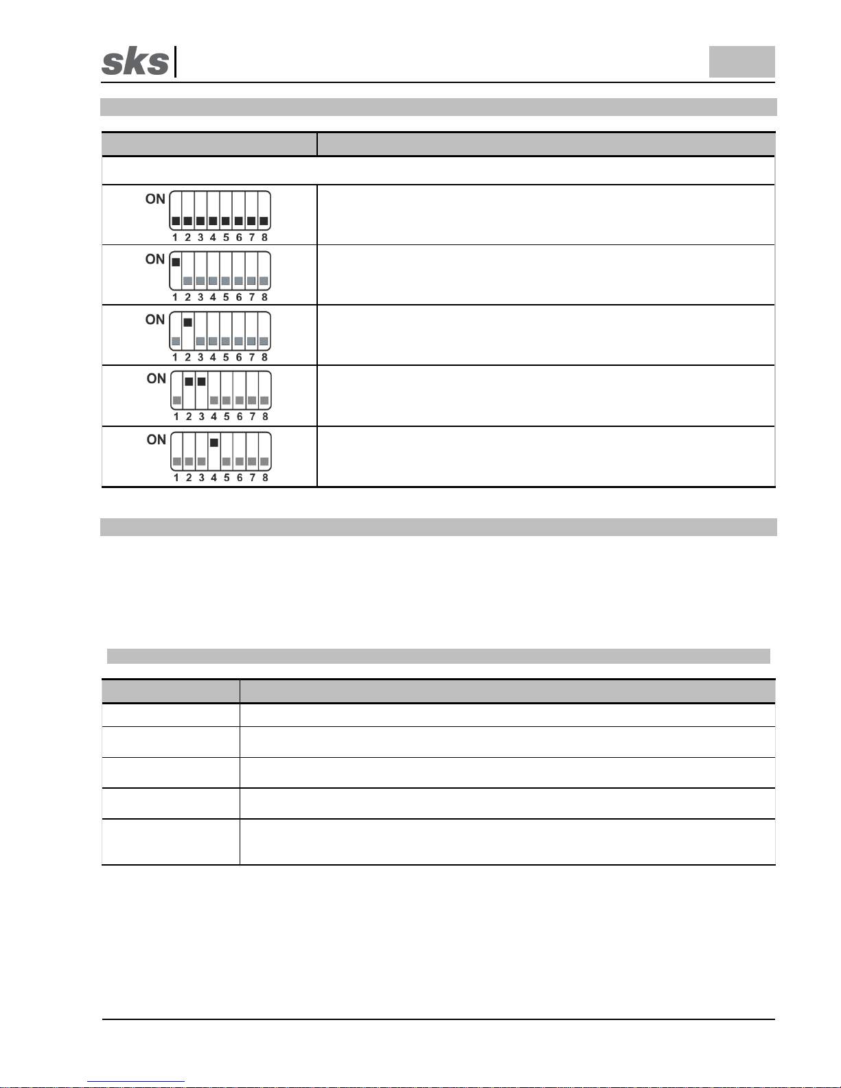
5 DIP- Schalter
DIP- Schalter Position
Betriebsart / Bedeutung
Für die beschriebenen Funktionen sind jeweils die schwarz hervorgehobenen DIP-Schalter von Bedeutung. Graue DIPSchalter haben für die jeweilige Funktion keine Relevanz. Somit ist eine Kombination der Funktionen möglich.
Normalbetrieb
Türöffnungszeit. Wird der DIP-Schalter 1 auf ON gestellt beträgt die
Türöffnerzeit 2 Sekunden. Wird der DIP-Schalter 1 auf OFF gestellt beträgt
die Türöffnerzeit 5 Sekunden.
Programmiermodus für Etagencontroller. Wird der DIP-Schalter 2 auf ON
gestellt befindet sich der Etagencontroller im Programmiermodus. Zum
Verlassen des Programmiermodus muss der DIP-Schalter 2 auf OFF gestellt
werden.
Löschen aller Rufadressen. Werden die DIP-Schalter 2 und 3 auf ON
gestellt, werden alle gespeicherten Rufadresse gelöscht. Die Löschzeit
beträgt 4 Sekunden. Nach der Löschzeit müssen die DIP-Schalter 2 und 3
wieder auf OFF gestellt werden. Weitere Informationen in Abschnitt 8.
Sprachen der Besetzt Ansage. Wird der DIP-Schalter 4 auf ON gestellt wird
nur eine Englische Besetzt Ansage wiedergegeben. Wird der DIP-Schalter 4
auf OFF gestellt wird eine Deutsche und Englische Besetzt Ansage
wiedergegeben.
6 Programmieren von Etagensprechstellen
Nachdem Sie die DIP-Schalter-Einstellungen am Etagen Kompaktnetzteil vorgenommen haben, beginnen Sie mit
der Programmierung der Rufadressen. Wenn das Etagen Kompaktnetzteil im Programmiermodus ist, kann nicht von
der Hauptlinie in die Etagenlinie gerufen werden. Die Programmierung kann über zwei Wege erfolgen. Die beiden
unten dargestellten Tabellen zeigen den Programmierablauf.
6.1 Programmierung über „S“-Taste auf der Etagensprechstelle
Arbeitsschritt
Beschreibung
1
Stellen Sie den DIP-Schalter 2 auf ON, die „Gespräch HL / Prog.“ LED leuchtet.
2
Überprüfen Sie die DIP-Schalter-Einstellungen für die Rufadresse der Etagensprechstelle
und betätigen Sie die „S“-Taste auf der Frontseite der Etagensprechstelle.
3
Bei jeder erfolgreich einprogrammierten Etagensprechstelle geht die „Gespräch HL / Prog.“
LED des Etagen Kompaktnetzteils 3 mal kurz aus und die Etagensprechstelle klingelt.
4
Wenn Sie weitere Rufadressen von Etagensprechstellen einprogrammieren wollen,
wiederholen Sie die Arbeitsschritte 2 und 3.
5
Sind alle Etagensprechstellen im Etagen Kompaktnetzteil erfolgreich einprogrammiert,
stellen Sie den DIP-Schalter 2 auf OFF, die „Gespräch HL / Prog.“ LED leuchtet nun nicht
mehr.
Page 6
SKS-Kinkel Elektronik GmbH
DE
300091 Etagen Kompaktnetzteil
Support-Hotline: +49 (0) 2661-98088-112
- 6 -
Version: 1.3
E-Mail: support@sks-kinkel.de Dokument Art. Nr. 97009603
6.2 Programmierung über die Klingeltasten auf der Etagentürstation
Arbeitsschritt
Beschreibung
1
Stellen Sie den DIP-Schalter 2 auf ON, die „Gespräch HL / Prog.“ LED leuchtet.
2
Betätigen Sie die erste Klingeltaste auf der Etagentürstation.
3
Bei jeder erfolgreich einprogrammierten Etagensprechstelle geht die „Gespräch HL / Prog.“
LED des Etagen Kompaktnetzteils 3 mal kurz aus.
4
Wenn Sie weitere Rufadressen von Etagentürstation einprogrammieren wollen,
wiederholen Sie die Arbeitsschritte 2 und 3. Warten Sie 2 Sekunden bis Sie die nächste
Klingeltaste an der Etagentürstation betätigen.
5
Sind alle Etagensprechstellen im Etagen Kompaktnetzteil erfolgreich einprogrammiert,
stellen Sie den DIP-Schalter 2 auf OFF, die „Gespräch HL / Prog.“ LED leuchtet nun nicht
mehr.
7 Löschen von einzelnen Etagensprechstellen
Das Löschen einzelner Etagensprechstellen ist über die Licht-Taste an der jeweiligen Etagensprechstelle möglich.
Wenn das Etagen Kompaktnetzteil im Programmiermodus ist, kann nicht von der Hauptlinie in die Etagenlinie
gerufen werden. Das Löschen erfolgt wie in der unten dargestellten Tabelle.
Arbeitsschritt
Beschreibung
1
Stellen Sie den DIP-Schalter 2 auf ON, die „Gespräch HL / Prog.“ LED leuchtet.
2
Betätigen Sie die Licht-Taste auf der zu löschenden Etagensprechstelle.
3
Bei jeder erfolgreich gelöschten Etagensprechstelle geht die „Gespräch HL / Prog.“ LED
des Etagen Kompaktnetzteils kurz aus und die Etagensprechstelle klingelt.
4
Sind die gewünschten Etagensprechstellen im Etagen Kompaktnetzteil erfolgreich
gelöscht, stellen Sie den DIP-Schalter 2 auf OFF, die „Gespräch HL / Prog.“ LED leuchtet
nun nicht mehr.
8 Löschen aller Etagensprechstellen
Das Löschen aller einprogrammierten Etagensprechstellen ist mit dem DIP-Schalter 3 am Etagen Kompaktnetzteil
möglich. Wenn das Etagen Kompaktnetzteil im Programmiermodus ist, kann nicht von der Hauptlinie in die
Etagenlinie gerufen werden. Das Löschen erfolgt wie in der unten dargestellten Tabelle.
Arbeitsschritt
Beschreibung
1
Stellen Sie den DIP-Schalter 2 auf ON, die „Gespräch HL / Prog.“ LED leuchtet nun.
2
Stellen Sie zusätzlich den DIP-Schalter 3 auf ON.
3
Während des Löschens blinkt die „Gespräch HL / Prog.“ LED des Etagen
Kompaktnetzteils. Nach dem Löschen blinkt die „Gespräch HL / Prog.“ Und „Betrieb /
Power“ LED.
4
Stellen Sie nach 4 Sekunden die DIP-Schalter 2 und 3 auf OFF, die „Gespräch HL / Prog.“
LED leuchtet nun nicht mehr.
Page 7
SKS-Kinkel Elektronik GmbH
DE
300091 Etagen Kompaktnetzteil
Support-Hotline: +49 (0) 2661-98088-112
- 7 -
Version: 1.3
E-Mail: support@sks-kinkel.de Dokument Art. Nr. 97009603
9 Technische Daten
Primärseite
Eingangsnennspannung
207 – 253 VAC / 50Hz
Sekundärseite
Ausgangsnennspannung TÖ
15V Rechteck-Wechselspannung (+5/-10%)
Ausgangsnennstrom TÖ
Aussetzbetrieb (EIN 5,5s/ AUS 11s) max. 1A
Ausgangsnennspannung LED
15VDC (+5/-10%)
Ausgangsnennstrom LED
max. 0,3 A
Ausgangsnennspannung aEL+ / bEL-
24VDC (+/-20%)
Ausgangsnennstrom aEL+ / bEL-
max. 1A
EMV-Norm, Sicherheit-Norm
EMV 2014/30/EU: EN55032 und EN55024, EG
2014/35/EU, EN60950-1
Allgemeines
Temperatur
-5°C bis +45°C
Feuchtigkeit
20% bis 90% nicht kondensierend
Gehäuse
Kunststoff Hutschienengehäuse
Abmessungen (Breite x Höhe x Tiefe)
105 x 90 x 71 mm (6TE)
Schutzart
IP20
Schutzmaßnahmen
Überspannungs- und Überlastschutz, Strombegrenzung
Netzanschlussklemmen L / N / PE
0,75mm² - 1,5mm², eindrähtig ohne Aderendhülse
0,75mm² - 1,5mm², feindrähtig mit Aderendhülse
Lastklemmen
aHL+ / bHL- / aEL+ / bEL- / LED+ / LED- / TÖ1/ TÖ2 / a
/ b / GND
0,13mm² - 1,29mm², eindrähtig
0,13mm² - 1,29mm², feindrähtig mit Aderendhülse
Page 8
SKS-Kinkel Elektronik GmbH
DE
300091 Etagen Kompaktnetzteil
Support-Hotline: +49 (0) 2661-98088-112
- 8 -
Version: 1.3
E-Mail: support@sks-kinkel.de Dokument Art. Nr. 97009603
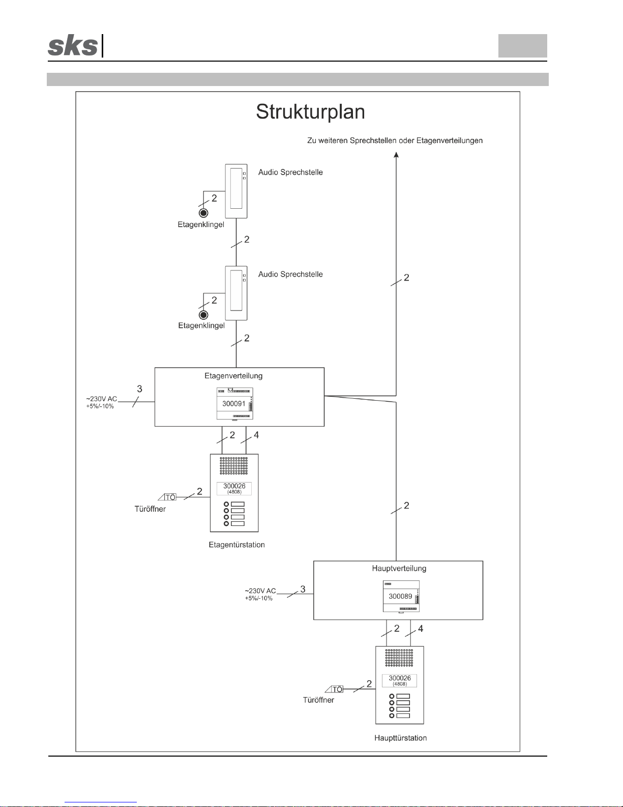
10 Strukturplan 2 Draht Audio
Page 9
SKS-Kinkel Elektronik GmbH
DE
300091 Etagen Kompaktnetzteil
Support-Hotline: +49 (0) 2661-98088-112
- 9 -
Version: 1.3
E-Mail: support@sks-kinkel.de Dokument Art. Nr. 97009603
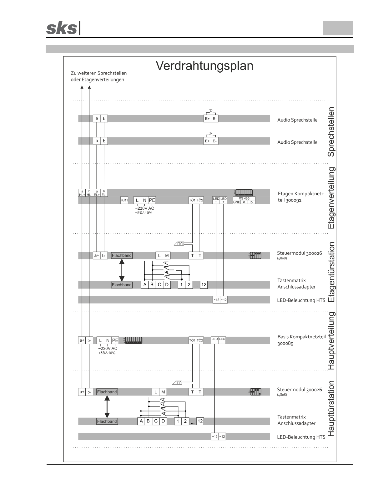
11 Verdrahtungsplan 2 Draht Audio
Page 10

SKS-Kinkel Elektronik GmbH
DE
300091 Etagen Kompaktnetzteil
Support-Hotline: +49 (0) 2661-98088-112
- 10 -
Version: 1.3
E-Mail: support@sks-kinkel.de Dokument Art. Nr. 97009603
12 Strukturplan 6 Draht Video
Page 11

SKS-Kinkel Elektronik GmbH
DE
300091 Etagen Kompaktnetzteil
Support-Hotline: +49 (0) 2661-98088-112
- 11 -
Version: 1.3
E-Mail: support@sks-kinkel.de Dokument Art. Nr. 97009603
13 Verdrahtungsplan 6 Draht Video
Page 12
SKS-Kinkel Elektronik GmbH
DE
300091 Etagen Kompaktnetzteil
Support-Hotline: +49 (0) 2661-98088-112
- 12 -
Version: 1.3
E-Mail: support@sks-kinkel.de Dokument Art. Nr. 97009603
14 Service
Für die Gewährleistung gelten die gesetzlichen Bestimmungen (vgl. hierzu auch unsere beigefügten bzw. im Internet unter
www.sks-kinkel.de/agb/ abrufbaren und einsehbaren AGB).
Abwicklung der Gewährleistung
Wir bieten unseren Kunden und auch Elektrofachkräften eine vereinfachte Abwicklung von Gewährleistungsfällen an. Dafür
beachten Sie die Verkaufs- und Lieferbedingungen auf unserer Internetpräsenz oder wenden Sie sich an unsere SKS-Support
Hotline.
Entsorgungshinweis
Durch die separate Sammlung von Elektro- und Elektronikaltgeräten soll die Wiederverwendung, die stoffliche Verwertung bzw.
andere Formen der Verwertung von Altgeräten ermöglicht sowie negative Folgen bei der Entsorgung der in den Geräten
möglicherweise enthaltenen gefährlichen Stoffe auf die Umwelt und die menschliche Gesundheit vermieden werden. Entsorgen
Sie die Verpackungsteile getrennt in Sammelbehältern für Pappe und Papier bzw. Kunststoff.
Die Produkte entsprechen den gesetzlichen Anforderungen, insbesondere dem Elektro- und Elektronikgerätegesetz und der
REACH-Verordnung.
(EU-Richtlinie 2012/19/EU WEEE und 2011/65/EU RoHS).
(EU-REACH-Verordnung und Gesetz zu Durchführung der Verordnung (EG) Nr.1907/2006).
Haftungsausschluss
Wir haben den Inhalt der Druckschrift auf Übereinstimmung mit der beschriebenen Hard- und Software geprüft. Es können
dennoch Abweichungen nicht ausgeschlossen werden, so dass wir für die vollständige Übereinstimmung keine Gewähr
übernehmen. Die Angaben dieser Druckschrift werden regelmäßig überprüft und notwendige Korrekturen sind in den
nachfolgenden Auflagen enthalten.
Service und Support
Unser Supportteam steht Ihnen mit Rat und Tat zur Seite und kümmert sich um Ihre Anliegen. Unser SKS-Support ist für Sie per
E-Mail und Telefon erreichbar. Bitte geben Sie stets eine möglichst genaue Fehlerbeschreibung, Projektbezeichnung, Ihren
Namen und Ihre Kundennummer mit an.
Folgende Möglichkeiten stehen Ihnen zur Verfügung:
SKS-Support Hotline
+49 (0) 2661 98088-112
SKS-Support E-Mail
support@sks-kinkel.de
Wir bieten ausschließlich Support für das Elektro-Handwerk, Architekten und Planungsbüros – Endkunden wenden sich bitte an
Ihren Elektro-Handwerksbetrieb
Anschrift
SKS-Kinkel Elektronik GmbH, Im Industriegebiet 9, 56472 Hof/ Westerwald
Tel.: +49 2661 98088-0, Fax: +49 2661 98088-200
E-Mail: info@sks-kinkel.de, www.sks-kinkel.de
Entsorgen Sie das Gerät nicht in den Hausmüll, sondern über eine Sammelstelle für Elektronikschrott. Die
zuständige Sammelstelle erfragen Sie bitte bei Ihrer Stadt- bzw. Kommunalverwaltung.
Page 13

SKS-Kinkel Elektronik GmbH
EN
300091 Floor compact power supply
Support-Hotline: +49 (0) 2661-98088-112
- 13 -
Version: 1.3
E-Mail: support@sks-kinkel.de Document art. no. 97009603
300091 Floor compact power supply
1 Installation
Electrical shock hazard to persons. Danger of burns, damage to device and malfunctions. Observe VDE 0100
and VDE 0800 guidelines during installation. (Germany)
Counter measures:
• Before beginning any work, deactivate and disconnect all energized electrical wires.
• Secure the switched off/ disconnected lines against erroneous reconnection.
• Use a measuring device to make sure that the wires are de energized.
• Cover up any adjacent, energized or conducting components.
• All work and all electrical connections must comply with the national provisions for the country in question
and must be performed by appropriately trained personnel.
DIN VDE 0100 must be observed and complied with in devices with a 230V connection.
1.1 Installation instructions and protection
The unit must be connected to the power supply that the user has no direct access to the terminal area.
Outside the device must be an easily accessible separator.
The device complies with overvoltage category II.
An overcurrent protection circuit needs to be installed ahead outside the device.
Install a fuse in front of the device.
The device must be connected to the conductor system or the potential equalization.
The device is rated to IP20 protection and it must be mounted on the DIN rail in distribution or plastic housing.
The device must be installed in a fire enclosure to IEC 60950-1.
Page 14

SKS-Kinkel Elektronik GmbH
EN
300091 Floor compact power supply
Support-Hotline: +49 (0) 2661-98088-112
- 14 -
Version: 1.3
E-Mail: support@sks-kinkel.de Document art. no. 97009603
1.2 Warning
Penetration of fluids or electrically conductive small parts can cause a short circuit, fire or electric shock. The
device must not be brought into contact with water or other liquids.
Avoid the entry of electrically conductive small parts through the vents.
The device generates heat in nominal operation. Provide a adequate ventilation.
Do not cover the ventilation slots on the device.
2 Terminal designation
Terminal
Designation
aEL+ / bEL-
Output a+ / b- floorline
LED+ / LED-
Output door opener
TÖ1 / TÖ2
Output door opener
aHL+ / aHL-
Output a+ / b- mainline
a / b / GND
RS485 connector
RJ11
compact interface
L / N / PE
Supply voltage
3 Description
In the simplest scenario the SKS bus installation consists of a single line. This is the so-called main line. Only one
call may be conducted at a time, even if there are several door stations. The floor compact power supply 300091
provides the opportunity to build on the floor lines. The floor line consists of at least one door station for that floor
and the intercom units that belong to it.
The floor compact power supply 300091 makes it possible to call direct from the floor door station in the floor line
and at the same time direct a call on the main line to an indoor station that is not located in the floor line.
The floor compact power supply is used whenever there are many door stations on every floor that are connected to
the main door station. If a call is to be directed from the main door station to a call station on the floor line while
another call is already being answered on another floor door station, there will be an acoustic busy signal.
The floor compact power supply is used whenever there are audio floor door stations and audio indoor stations
being used with audio communication to the main door stations. In connection with the extended video compact
power supply 300092 it is possible to operate video floor door stations and video indoor stations in the floor line.
There is also the possibility connect up to 30 nameplate illuminations as well as the door opener.
Image retrieval from floor indoor station to the main door station is not possible whereas image retrieval from the
floor call station to the floor door station is possible.
The floor compact power supply is protected against overload and short circuiting.
Page 15

SKS-Kinkel Elektronik GmbH
EN
300091 Floor compact power supply
Support-Hotline: +49 (0) 2661-98088-112
- 15 -
Version: 1.3
E-Mail: support@sks-kinkel.de Document art. no. 97009603
4 LED display
The device features several LED displays which provide information on the current operational status. Please find
below an explanation of the information shown on the display.
4.1 Betrieb / Power LED
The Betrieb / Power- LED indicate the operation mode of the floor compact power supply 300091. The table below
shows the different stages.
Status LED
Description
LED on
Operative
LED flashes
No call addresses programmed
LED off
Outputs switched off
4.2 Gespräch HL / Prog.
The LED „Gespräch HL / Prog.“ indicates two different states as explained in the table below.
Status LED
DIP switch 2
Description
LED on
in „OFF“ position
A call is directed from the main line (HL) to the floor line
(EL)
LED flashing
in „ON“ position
The floor compact power supply has deactivated the
programming mode after the programming time has
elapsed. Set DIP 2 and 3 back to OFF.
LED on
in „ON“ position
The floor compact power supply is in programming
mode
4.3 Störung- LED
Depending on the fault that has occurred, the floor compact power supply 300091 will generate a diagnostic error
code. This is indicated by the Störung- LED.
In case of an error the Störung- LED will flash about 1 time per second. Once the LED has lit up the respective
number of times it will stay off for 5 seconds. After that it will come on again and flash accordingly. The table below
shows the number of times the Störung- LED will flash to indicate the respective fault.
LED flashes
Definition
1x
Minimum input voltage not reached by far
3x
Capacity of heat dissipation exceeded
4x
Total current briefly too high
5x
Total current too high for a longer period
7x
12V-output voltage too low
8x
12V-output excess current
The LED indicates the most recently recognized fault for one day. Once a fault has been detected, the outputs are
shut down for 30 seconds. If a fault occurs repeatedly, there will be a shut-off of 6 minutes.
Page 16

SKS-Kinkel Elektronik GmbH
EN
300091 Floor compact power supply
Support-Hotline: +49 (0) 2661-98088-112
- 16 -
Version: 1.3
E-Mail: support@sks-kinkel.de Document art. no. 97009603
5 DIP-Switch
DIP- switch position
Operation mode
Normal operation
Door opening time. If the DIP switch is set to ON, the door release time is 2
seconds. If the DIP switch is set to OFF, the door opening time is 5 seconds.
Programming mode for floor controller. If the DIP switch is set to ON, the
floor controller is in programming mode. To exit the programming mode, the
DIP switch must be set to OFF.
Delete all call addresses. If DIP switches 2 and 3 are set to „ON“, all stored
calls addresses are deleted. Deletion time is 4 seconds. After this delete
period DIP switches 2 and 3 have to be reset to the “OFF” position. More
information in section 8.
Languages of the busy announcement. If the DIP switch 4 is set to ON,
only an English busy announcement is played. If DIP switch 4 is set to OFF, a
German and English busy announcement is played back.
6 Programming floor intercoms
After you have completed the DIP-switch settings on the floor compact power supply, begin programming the call
addresses of the floor indoor stations. When the floor compact power supply is in programming mode, calls cannot
be made from the main line to the floor line. Programming can be done two ways. The two tables below show the
programming process.
6.1 Programming using “S”-Button at the floor indoor station
Step
Description
1
Set the DIP-Switch 2 on the floor compact power supply to the ON position until the
„Gespräch HL / Prog.“ LED lights up.
2
Check the DIP-switch settings for the call address for the floor indoor station and press the
S button on the floor indoor station.
3
For each successfully programmed floor indoor station, the „Gespräch HL / Prog.“ LED
goes off briefly three times and the floor indoor station rings.
4
If additional call addresses of floor call stations are to be programmed, repeat steps 2 and
3.
5
If all floor indoor stations have been programmed into the floor compact power supply, Set
the DIP-Switch 2 on the floor compact power supply to the OFF position until the
„Gespräch HL / Prog.“ LED turns off.
Page 17

SKS-Kinkel Elektronik GmbH
EN
300091 Floor compact power supply
Support-Hotline: +49 (0) 2661-98088-112
- 17 -
Version: 1.3
E-Mail: support@sks-kinkel.de Document art. no. 97009603
6.2 Programming using the bell buttons on the floor door station
Step
Description
1
Set the DIP-Switch 2 on the Floor compact power supply to the ON position until the
„Gespräch HL / Prog.“ LED lights up.
2
Press the first bell button on the floor station.
3
For each successfully programmed floor indoor station, the „Gespräch HL / Prog.“ LED
goes off briefly three times.
4
If additional call addresses of floor call stations are to be programmed, repeat steps 2 and
3. Wait 2 seconds until you press the next bell button on the floor door station
5
If all floor indoor stations have been programmed into the floor compact power supply, set
the DIP-Switch 2 on the floor compact power supply to the OFF position until the
„Gespräch HL / Prog.“ LED turns off.
7 Deleting floor indoor stations
You can only delete single floor indoor stations using the light button on the floor indoor station. If the floor compact
power supply is in programming mode, you cannot call from the main line to the floor line. To delete, proceed as
described in the table below.
Step
Description
1
Set the DIP-Switch 2 on the Floor compact power supply to the ON position until the
„Gespräch HL / Prog.“ LED lights up.
2
Press the light button on the floor indoor station delete this floor indoor station.
3
For each successfully deleted floor indoor station, the „Gespräch HL / Prog.“ LED goes off
briefly and the floor indoor station rings.
4
If all floor indoor stations have been programmed into the floor compact power supply, Set
the DIP-Switch 2 on the floor compact power supply to the OFF position until the
„Gespräch HL / Prog.“ LED turns off.
8 Deleting all floor indoor stations
You can delete all programmed indoor station with the DIP-Switch 3 on the floor compact supply. If the floor compact
power supply is in programming mode, you cannot call from the main line to the floor line. To delete, proceed as
described in the table below.
Arbeitsschritt
Beschreibung
1
Set the DIP-Switch 2 on the Floor compact power supply to the ON position until the
„Gespräch HL / Prog.“ LED lights up.
2
Set the DIP-Switch 3 on the Floor compact power supply also to the ON position
3
During deletion the „Gespräch HL / Prog.“ LED will blink. Once deleted, the „Gespräch HL
/ Prog.“ and “Betrieb / Power” LED will flash.
4
After 4 seconds set the DIP-Switch 2 and 3 on the floor compact power supply to the OFF
position until the „Gespräch HL / Prog.“ LED turns off.
Page 18

SKS-Kinkel Elektronik GmbH
EN
300091 Floor compact power supply
Support-Hotline: +49 (0) 2661-98088-112
- 18 -
Version: 1.3
E-Mail: support@sks-kinkel.de Document art. no. 97009603
9 Technical data
Primärseite
Input rated voltage
207 – 253 VAC / 50Hz
Sekundärseite
Output rated voltage TÖ
15 V rectangular alternating voltage (+5/-10%)
Output rated current TÖ
Intermittent (ON 5,5s / OFF 11s) max. 1 A
Output rated voltage LED
15VDC (+5/-10%)
Output rated current LED
max. 0,3 A
Output rated voltage aEL+ / bEL-
24VDC (+/-20%)
Output rated current aEL+ / bEL-
max. 1A
EMV-standard, safety standard
EMV 2014/30/EU: EN55032 und EN55024, EG
2014/35/EU, EN60950-1
Allgemeines
Temperature
-5°C up to +45°C
Humidity
20% bis 90% non-condensing
Housing
Plastic top-hat rail housing
Dimensions (width x height x depth)
105 x 90 x 71 mm (6HP)
Type
IP20
Protection measures
Overvoltage and overload protection, current limit
Power input terminal L / N / PE
0.75mm² - 1.5mm², solid without ferrule
0.75mm² - 1.5mm², flexible with ferrule
Load Terminal
aHL+ / bHL- / aEL+ / bEL- / LED+ / LED- / TÖ1/ TÖ2 / a
/ b / GND
0.13mm² - 1.29mm², solid without ferrule
0.13mm² - 1.29mm², flexible with ferrule
Page 19

SKS-Kinkel Elektronik GmbH
EN
300091 Floor compact power supply
Support-Hotline: +49 (0) 2661-98088-112
- 19 -
Version: 1.3
E-Mail: support@sks-kinkel.de Document art. no. 97009603
10 Structure plan 2 wire Audio
Page 20
SKS-Kinkel Elektronik GmbH
EN
300091 Floor compact power supply
Support-Hotline: +49 (0) 2661-98088-112
- 20 -
Version: 1.3
E-Mail: support@sks-kinkel.de Document art. no. 97009603
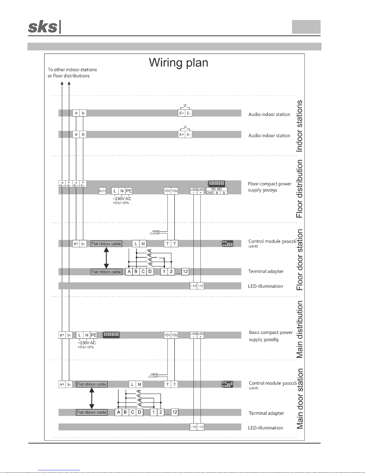
11 Wiring plan 2 wire audio
Page 21

SKS-Kinkel Elektronik GmbH
EN
300091 Floor compact power supply
Support-Hotline: +49 (0) 2661-98088-112
- 21 -
Version: 1.3
E-Mail: support@sks-kinkel.de Document art. no. 97009603
12 Structure plan 6 wire video
Page 22
SKS-Kinkel Elektronik GmbH
EN
300091 Floor compact power supply
Support-Hotline: +49 (0) 2661-98088-112
- 22 -
Version: 1.3
E-Mail: support@sks-kinkel.de Document art. no. 97009603
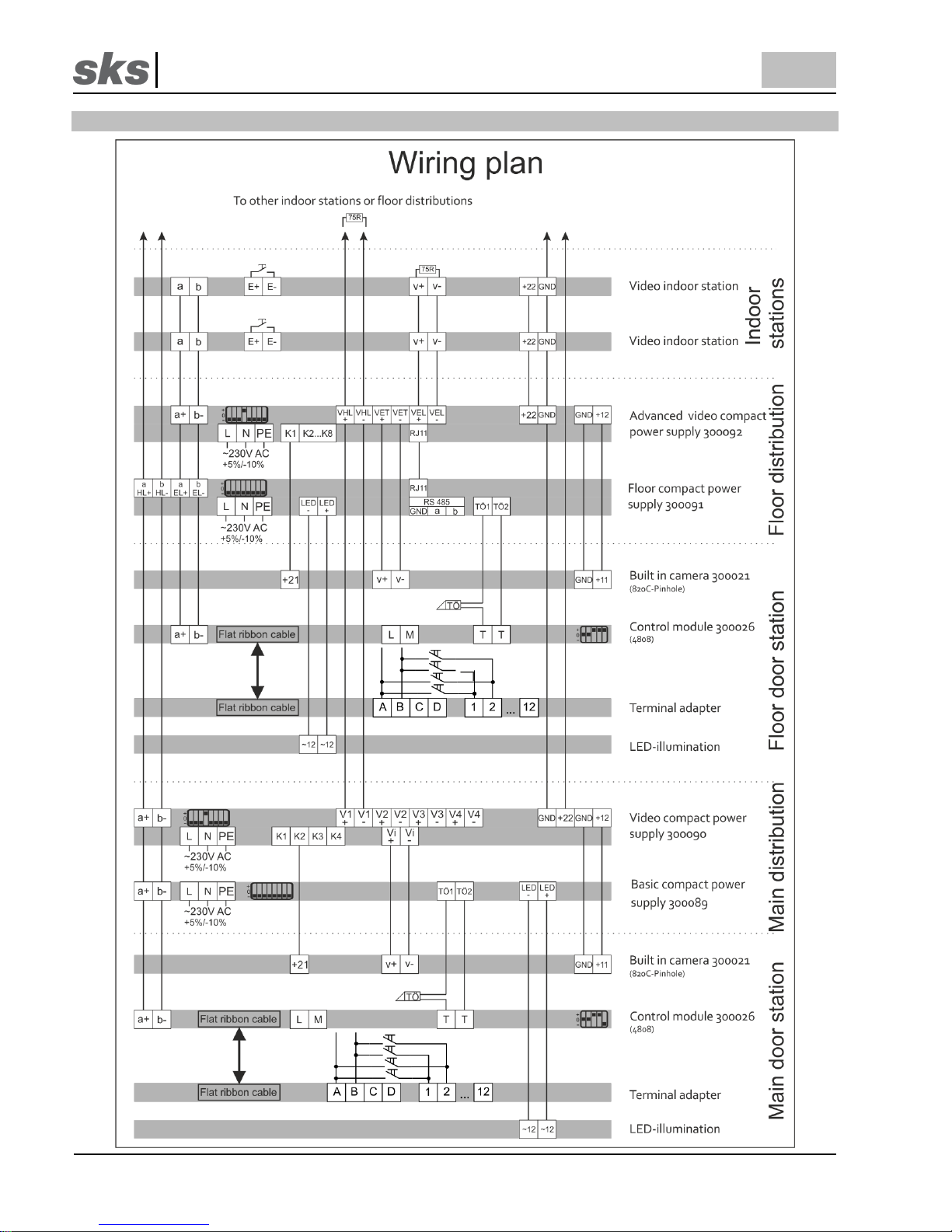
13 Wiring plan 6 wire video
Page 23

SKS-Kinkel Elektronik GmbH
EN
300091 Floor compact power supply
Support-Hotline: +49 (0) 2661-98088-112
- 23 -
Version: 1.3
E-Mail: support@sks-kinkel.de Document art. no. 97009603
14 Service
Statutory provisions for warranty shall apply. (See general terms and conditions in the appendix or the internet at www.skskinkel.de/agb/)
Warranty
Our customers and electricians are offered a simplified settlement process of the warranty claim. For more information on this
please refer to the terms and conditions on our internet page or contact the SKS support hotline.
Disposal instructions
By separately disposing of electrical and electronic devices you will allow for the reuse, renewing and recycling of materials and
used appliances and equipment. At the same time this separation shall prevent negative effects of the possibly existing
dangerous substances and materials on the environment and public health. Dispose of the packaging in the respective separate
containers for cardboard, paper and plastics.
The products comply with the regulatory requirement, in particular with electrical and electronic equipment act and the REACHregulation.
(EU- guideline 2012/19/EU WEEE and 2011/65/EU RoHS).
(EU-REACH- regulation and the law implementing regulation (EG) Nr.1907/2006).
Liability disclaimer
We have checked the content of this document to verify that it corresponds to the hard- and software described herein. There
may, however, be deviations and SKS-Kinkel GmbH may not be held liable for a lack of conformity. The information in this
document is checked regularly and necessary changes are made in subsequent issues.
Service and support
Our support team provides practical assistance and advice. SKS support may be reached via email or phone. When contacting
us please provide an exact description of the fault, the project name your name and your customer ID.
We provide the following options:
SKS-Support Hotline
+49 (0) 2661 98088-112
SKS-Support E-Mail
support@sks-kinkel.de
Support is exclusively provided for electricians, architects or planning offices. End customers are asked to contact their
electrician.
Address
SKS-Kinkel Elektronik GmbH, Im Industriegebiet 9, 56472 Hof/ Westerwald
Tel.: +49 2661 98088-0, Fax: +49 2661 98088-200
E-Mail: info@sks-kinkel.de, www.sks-kinkel.de
Do not dispose of the device with the regular household refuse but take it to a collection point for electronic
scrap. The respective collection point is provided by the municipal administration in the area.
Page 24

SKS-Kinkel Elektronik GmbH
300091 Etagen Kompaktnetzteil
Support-Hotline: +49 (0) 2661-98088-112
- 24 -
Version: 1.3
E-Mail: support@sks-kinkel.de Dokument Art. Nr. 97009603
15 Anhang, appendix
DIP-Schaltereinstellungen für Innensprechstellen, Schaltaktor und TK
-Adapter
DIP-Switch settings for intercoms,
switch actuator
and TK
-Adapter
Standard
Rufadressbereich
Erweiterter
Rufadressbereich
Standard
call address range
Extended
call address range
 Loading...