

Page 1

SC-1 System Controller
OWNER'S MANUAL
SKRYDSTRUP R&D CUSTOM BUILT AUDIO & SWITCHING SYSTEMS
Page 2

SC-1 System Controller Manual
Contents
Introduction 3
Warranty 4
Precautions 5
1. Top panel
1.1 Primary functions of switches.
1.2 Secondary functions of switches.
2. Rear panel 9
3. Midi devices 10
4. Operating the SC-1 11
5. SC-1 menu schematic 12
6. Getting started 13
7. Operation modes 14
8. Preset mode 15
9. Song mode
9.1 Accessing the song mode
9.2 Modifying a song
0. Set mode
10.1 Accessing the set mode
10.2 Editing the set
1. Midi menu
11.1 Program Change menu
11.2 Controllers menu
11.3 Pedals menu
2. Titles menu 25
3. Copy menu
13.1 Copy a bank-preset
13.2 Copy a song
4. System menu
14.1 Midi Bulk
14.2 Version
14.3 Restore
14.4 Pedals
5. Cables 30
6. Midi appendix 31
6
16
18
20
26
27
2
Page 3

SC-1 System Controller Manual
Introduction
Congratulations on your purchase of the SRD SC-1 System Controller.
The SC-1 System Controller was designed to provide ultimate flexibility in MIDI
controlling, combined with a rugged design for years of trouble free and reliable
use.
This manual will introduce you to the SC-1 System Controller and its features.
After reading this manual carefully please keep it for future reference.
We are confident that you very quickly will be familiar with the SC-1 System
Controller, and appreciate the versatility and high quality of this unit.
Steen Skrydstrup.
President.
SKRYDSTRUP RESEARCH & DEVELOPMENT
MOEGELMOSEVEJ 54
DK-6630 ROEDDING
DENMARK.
Tel.: +45 7536 6174
Fax: +45 7536 6179
Web: www.skrydstrup.com
3
Page 4

SC-1 System Controller Manual
Warranty
• All parts and workmanship of this SKRYDSTRUP R&D product are fully guaranteed
to be free of defects under normal use and service for a period of TWO years from
date of purchase.
• This warranty will remain in effect until the original expiration date.
• Any damage resulting from mis-use or failure to follow instructions and precautions
as stated in this manual, will void this warranty.
• Should this product require repair, SKRYDSTRUP R&D will assume responsibility
for repair service. Re-pack the unit, along with a description of the problem, and
send it to SKRYDSTRUP R&D.
• Removing or altering the original serial number, will void this warranty.
• Altering this product in general, will void this warranty.
• SKRYDSTRUP R&D reserves the right to make changes in design and/or
improvements upon this product, without any obligation to include those changes in
any products previously manufactured.
4
Page 5

SC-1 System Controller Manual
Precautions
NOTE: IT IS VERY IMPORTANT THAT YOU READ THIS SECTION
CAREFULLY TO PROVIDE YEARS OF TROUBLE FREE USE.
THIS UNIT REQUIRES CAREFUL USE.
DO NOT…
• ATTEMPT TO SERVICE THIS EQUIPMENT. QUALIFIED PERSONNEL
SHOULD SERVICE THIS EQUIPMENT ONLY.
• REMOVE THE COVER FROM THIS EQUIPMENT AT ANY TIME.
• MAKE INTERNAL ADJUSTMENTS OR ADDITIONS TO THIS
EQUIPMENT AT ANY TIME.
• TAMPER WITH INTERNAL ELECTRONIC COMPONENTS AT ANY
TIME. FAILURE TO FOLLOW THESE INSTRUCTIONS MAY VOID
WARRANTY SERVICE TO THIS EQUIPMENT, AS WELL AS SHOCK
HAZARD.
• EXPOSE THIS UNIT TO EXCESSIVE HEAT. THIS UNIT IS DESIGNED
TO OPERATE BETWEEN O° C AND 40° C.
• USE THIS EQUIPMENT NEAR WATER. CARE SHOULD BE TAKEN
SO THAT OBJECTS DO NOT FALL AND LIQUIDS ARE NOT SPILLED
INTO THE UNIT THROUGH ANY OPENINGS.
• USE SOLVENTS SUCH AS BENZINE, ETC. TO CLEAN THE
EXTERIOR. USE A DRY SOFT CLOTH TO REMOVE DUST, DIRT OR
FINGERMARKS.
5
Page 6
6
Page 7
456
213
8
SC-1 System Controller Manual
1. Top Panel
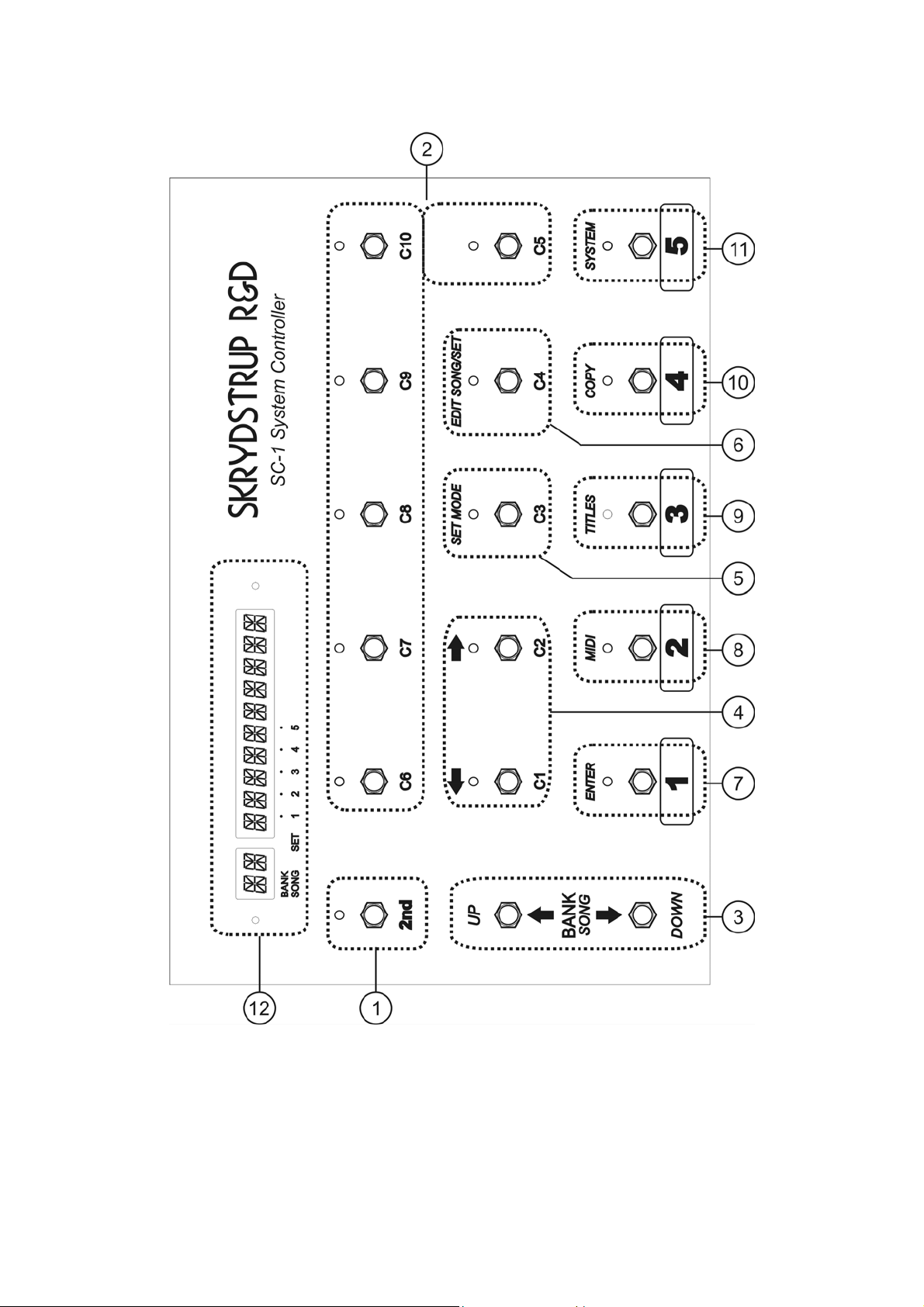
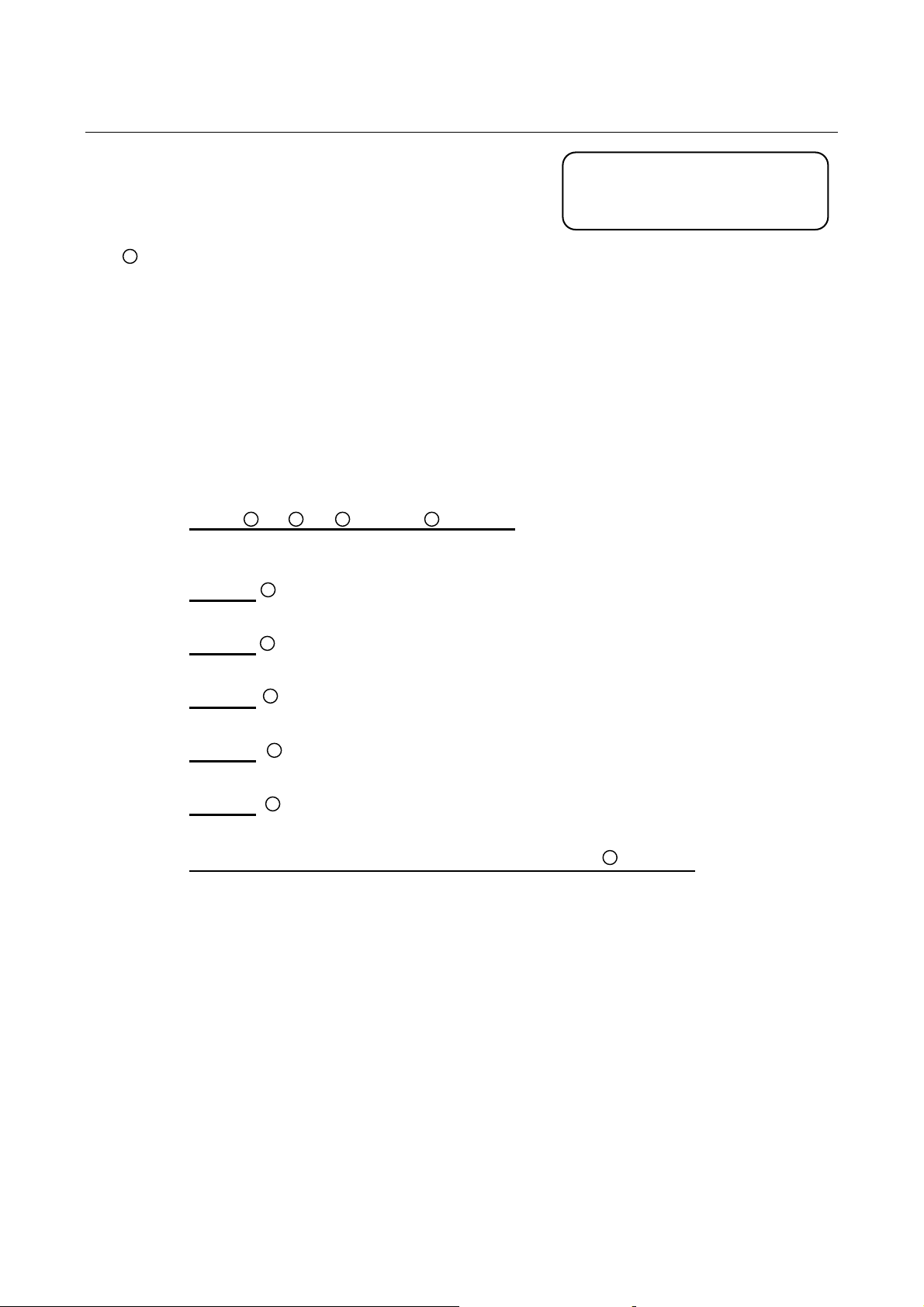
2ND switch:
This switch selects between the primary and the secondary function of every switch on the
SC-1.
The primary function of all switches corresponds to the label below the switch, while the
secondary function corresponds to the label above the switch. When this switch is pressed the
LED turns on, indicating the secondary functions are available. When the switch is pressed
again, the LED turns off, indicating the primary functions are available.
1.1 Primary function of the switches:
C1 - C2 , C3 , C4 , C5 - C10 switches:
The primary functions of these switches are to initiate the corresponding MIDI controller
change transmissions, if programmed.
1 switch:
Recalls preset number 1.
2 switch:
Recalls preset number 2.
3 switch:
Recalls preset number 3.
4 switch:
Recalls preset number 4.
5 switch:
Recalls preset number 5.
UP ARROW
The function of these switches are to decrement and increment the bank number and song
number.
If pressed and held down, the bank or song number will be scrolled, until either of the
switches is released.
7
9
10
11
“”and DOWN ARROW “” (BANK/SONG) switches:
The numbers inside the circles
refers to the numbers on the
drawing page 6.
7
Page 8
456
9
3
SC-1 System Controller Manual
1.2 Secondary function of the switches:
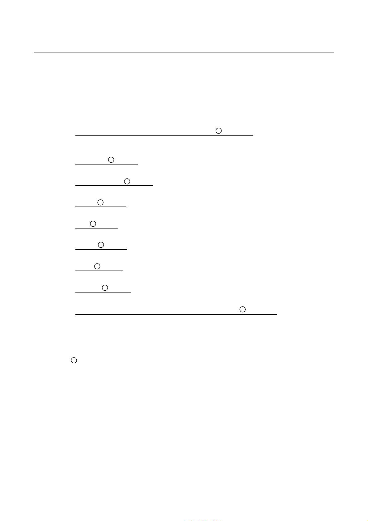
LEFT “” ARROW and C2/ RIGHT “” ARROW switches:
The secondary function for these switches is to move the cursor in the 12-character display
between the sections available and to step forward and backwards in the various menus.
DISPLAY
SET MODE switch:
Enters the SET MODE menu.
EDIT SONG/SET switch:
Enters the EDIT SONG/SET menu.
ENTER switch:
Used for selecting menus, storing changes, executing functions, etc.
MIDI switch:
Enters the MIDI menu.
TITLES switch:
Enters the TITLES edit function.
COPY switch:
Enters the COPY function.
SYSTEM switch:
Enters the SYSTEM menu.
UP ARROW
The function of these switches are to decrement and increment the bank number and song
number.
If pressed and held down, the bank or song number will be repetitive accelerating
decremented or incremented, until either of the switches is released.
12
7
8
10
11
“”and DOWN ARROW “” (BANK/SONG) switches:
It is used to display user-programmed preset or song titles, as well as programmed MIDI data,
system status and system messages.
The decimal points are used to indicate if set mode is active and which set number is active.
The display consists of 12 alphanumeric characters of 14 segments each.
8
Page 9
SC-1 System Controller Manual
2. Rear Panel
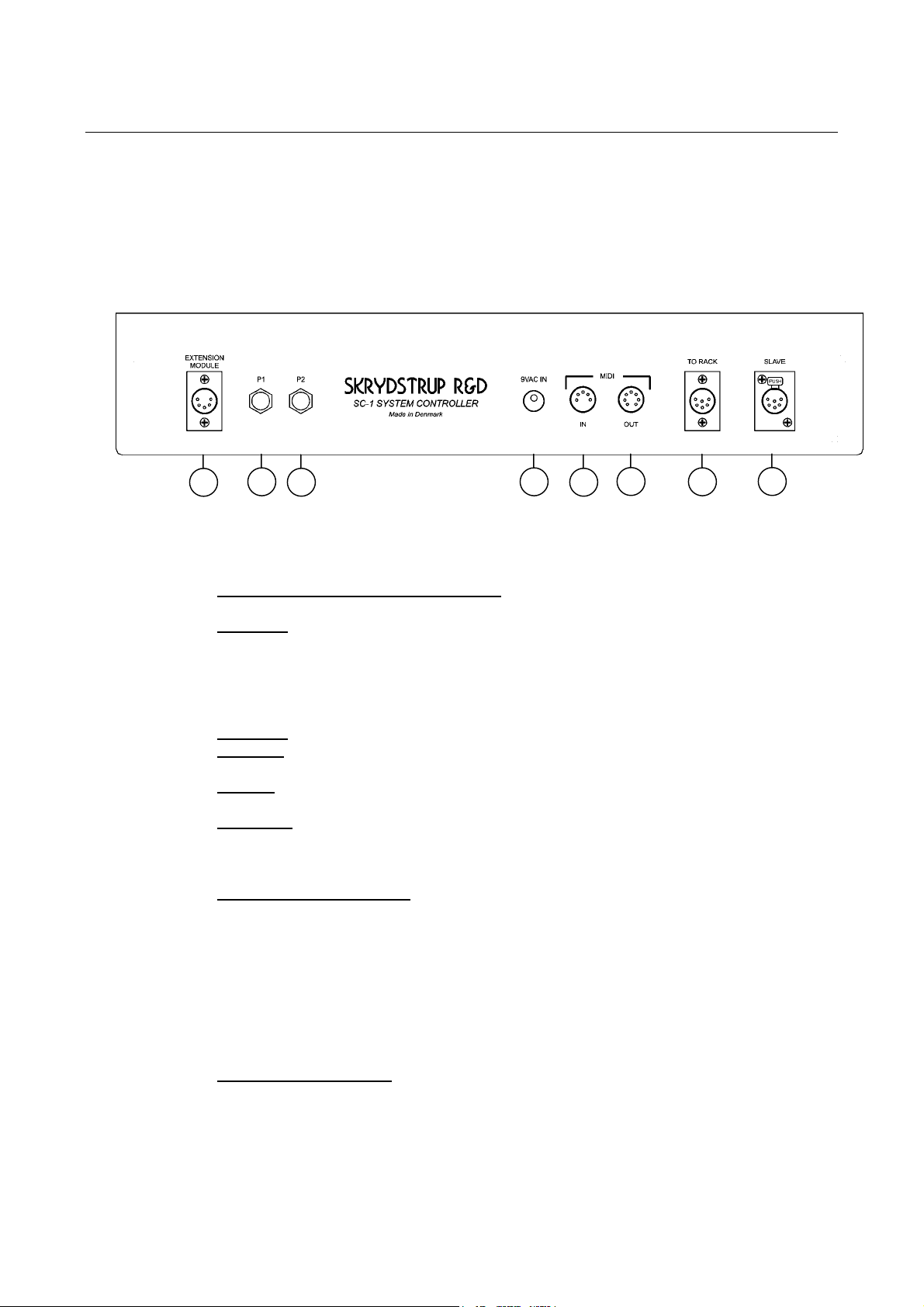
1
1) EXTENSION MODULE XLR Connector:
2) P1 JACK:
3) P2 JACK:
4) 9VAC IN: 2.1mm DC bushing for supplying the SC-1 with 9VAC.
5) MIDI IN:
6) MIDI OUT:
7) TO RACK XLR Connector:
2
3
provide power as well as information lines between SC-1 and the Extension Module.
standard ¼” stereo.
This jack provides connection for an external expression pedal.
Tip=pedal input Ring=pedal output Sleeve=ground
The ring of this jack is internally wired to +5V through a 200 Ohm resistor, so that external
short circuits will not damage the unit. Maximum resistance of the expression pedal is not
critical (see section 15 for further information).
same specifications as P1 jack.
The SC1 will require a min. of 300mA, and 375mA with the Extension.
5-pin DIN connector providing the SC-1 with incoming MIDI data. This connector
is used for MIDI Bulk Load and firmware-update functions.
7-pin DIN connector. This 7-pin connector takes a 7-pin MIDI cable to provide
power for the SC-1, as well as sending MIDI data to external MIDI devices. This connector
can be used together with MIDI IN on SKRYDSTRUP R&D MR-8 Loop System.
A common 5-pin MIDI cable can also be used, if the 9VAC in is used for powering.
This 6-pin XLR connector takes a cord to provide power as
well as MIDI IN/OUT information lines between the SC-1 and a SKRYDSTRUP R&D
System Interface.
The PIN configuration is:
PIN 1 : 9VAC
PIN 2 : MIDI IN +
PIN 3 : MIDI OUT +
PIN 4 : MIDI OUT PIN 5 : MIDI IN PIN 6 : 9VAC
4
This 5-pin XLR connector takes a cord to
5
6
7
8
8) SLAVE XLR Connector: This 6-pin XLR connector takes a cord to provide power as well
as information lines between additional SC-1’s. Contact factory for details.
9
Page 10
SC-1 System Controller Manual
3. Midi devices
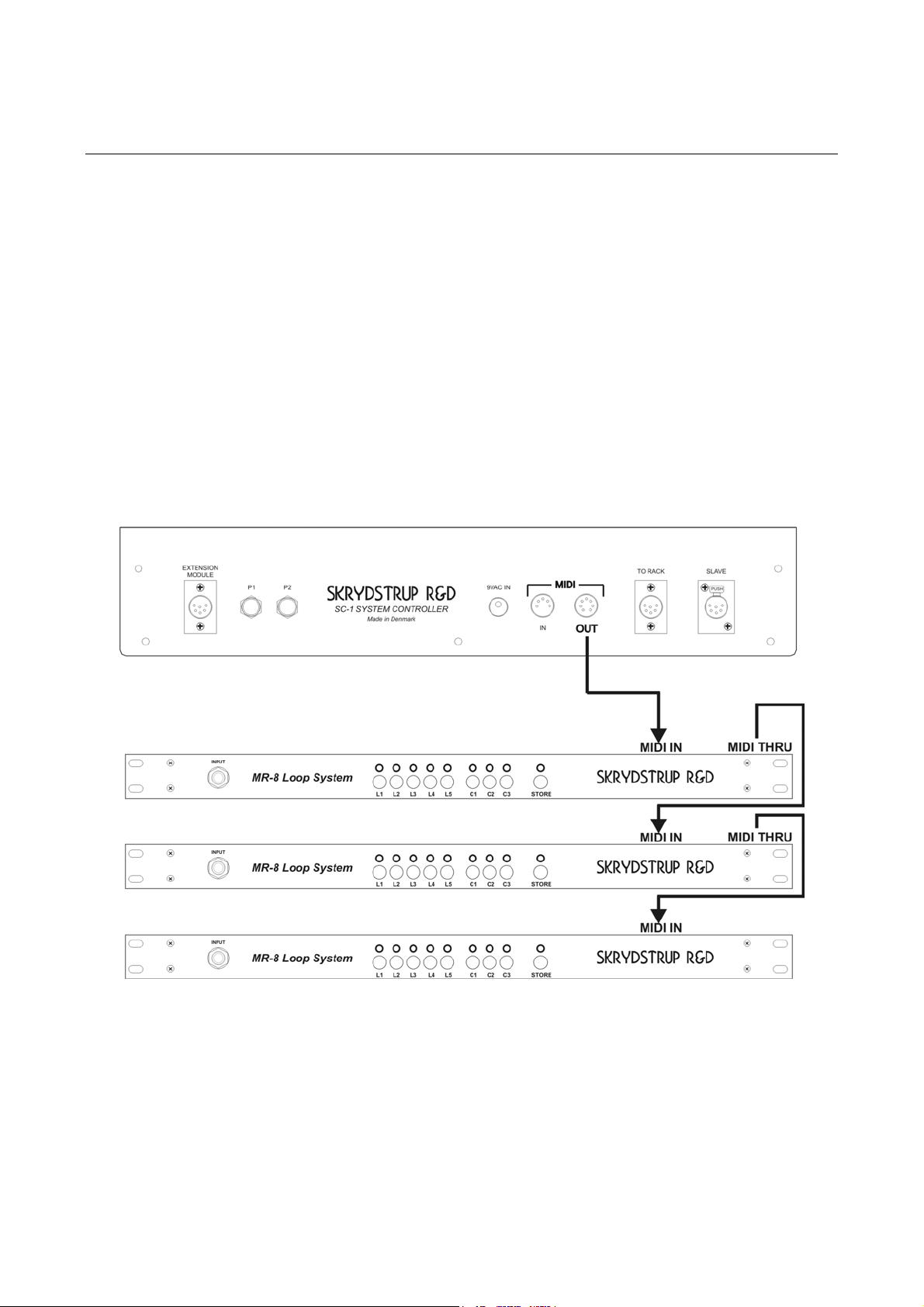
External MIDI devices can be connected to the SC-1 MIDI Out. The MIDI Thru of the first MIDI device passes
on the original MIDI signal sent to MIDI In. There is a limit to how many MIDI devices you can connect like
this – in series.
A distortion and delay of the MIDI signal can occur, causing errors in the MIDI signal.
To solve this problem a MIDI Thru Box can be used. A MIDI Thru Box will supply multiple buffered MIDI
Outs. Keep MIDI cables as short as possible, not exceeding 15 meters in length.
SC-1 rear
10
Page 11

SC-1 System Controller Manual
4. Operating the SC-1
To get quickly started using the SC-1 there is some basic concepts regarding the user
interface that is worth knowing for better and faster operation of the machine.
4.1 Primary operation
When operating in primary mode the preset switches 1-5 are used for selecting presets, the
controller switches C1-C10 are used for control change operations, the up
“” arrows selects the bank or song number which is shown in the BANK/SONG part of the
display. The title of the preset/song is shown in the larger 10-character part of the display.
The preset switches selects one of the five presets available in each bank/song. When
pressing one of these switches the selected preset will be instantly recalled and all pre
programmed MIDI data will be sent.
The controller switches C1-C10 are used for sending MIDI control change messages. When
recalling a preset the states of the controllers are used for sending either on (7Fh) or off (00h)
control changes to i.e. a loop system or an effects processor. These controllers can also be
toggled while using the preset by pressing the desired controller. A controller can be turned off
– so don’t be alarmed if a controller does not respond. Storing the change is done by pressing
nd
2
followed by ENTER (only in preset mode). When repressing the selected preset switch,
the preset is restored to its last stored state.
The up
pressing either of these switches the BANK/SONG display will start blinking, indicating that
the shown bank/song number is not the current. Pressing a preset number will recall the
selected preset number in the selected bank.
When operating in set mode the dot-points in the bottom of the display indicates the current
set number.
4.2 Secondary operation
Pressing the 2nd switch accesses the secondary mode. The 2
secondary functions are available. These functions are listed above the switches. By pressing
any of the titled switches you will access the features of the selected function.
Many of these functions use menus where you can scroll between the menu items by
pressing the up
the desired menu item. Press the left arrow “” to step back to the previous menu or press
the function switch the go back to the root of the menu.
A blinking dot-point appears when entering a page where parameters can be edited. This dotpoint is your cursor and can be moved between the parameters with the left and right arrows.
The parameter can be altered with the up
positioned next to it. Stepping back to the previous menu is done be moving the cursor to the
first parameter and pressing the left “” arrow.
Please note: Not all of the secondary functions are available in some operating modes.
See the detailed descriptions of the secondary functions (referred to as “menus”) further on in
this manual.
“” and down “” arrows lets you select the current bank or song number. When
“” and down “” arrows. Press the right arrow “” or ENTER to select
“” and down “” arrows when the cursor is
“”and down
nd
LED will be lit indicating that
11
Page 12
A
SC-1 System Controller Manual
5. SC-1 menu schematic
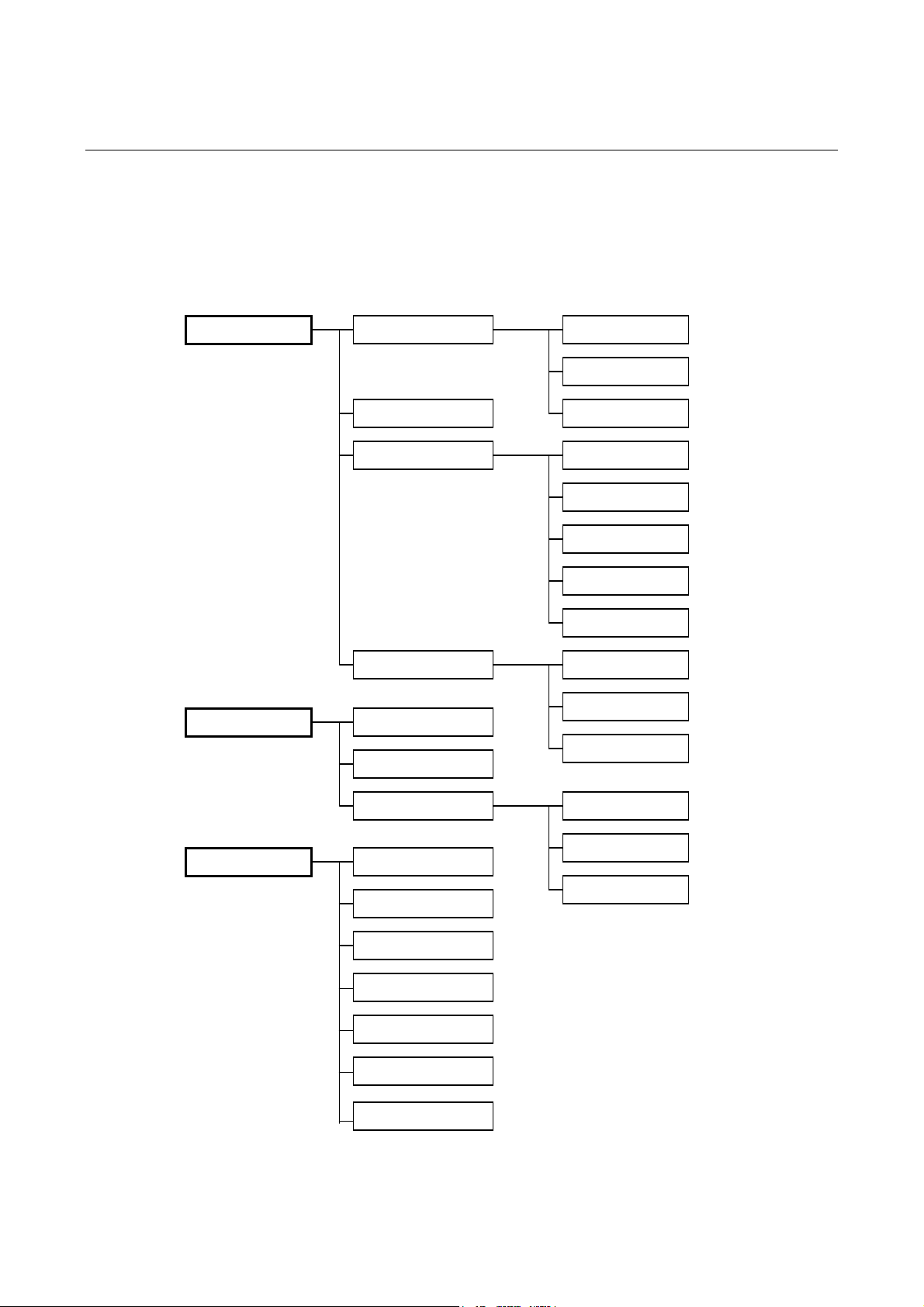
Below is shown a rough schematic layout of the three most important menus in the SC-1.
MIDI BULK
VERSION
RESTORE
PEDALS
PRG CHANGE
CONTROLLER
PEDALS VALUE
PRESET
SONG
SET 1
SET 2
SET 3
SET 4
SLAVE
BULK DUMP
BULK LOAD
CALIBRATE
DEVICE ID
LL
GLOBALS
SET
SONG
PRESETS
GRAB
SCALE
GLOBALS
MIDI CC#
12
Page 13

SC-1 System Controller Manual
6. Getting started
1. Connect a Midi cable from SC-1 Midi Out to your system (See section 3)
2. Connect the 9VAC power supply to SC-1.
SC-1 is now functional.
To start using the SC-1 with your system, follow step 3 thru 11.
3. Select how you want the SC-1 to operate (See section 7)
4. Set up your controllers (See section 11)
5. Set up the scale of your external pedals used in P1/P2 (See section 14)
6. Calibrate your pedals (See section 14)
7. Set up the controller number and channel for each pedal used (See section 11)
8. If PDL VAL is selected ON, set up the actual pedal value (See section 11)
9. Set up any Midi Program Change messages you want to send (See section 11)
10. Rename your presets with a unique title (See section 12)
Step 8, 9 and 10 is repeated in every preset used.
You are now ready to perform with the SC-1.
13
Page 14

SC-1 System Controller Manual
7. Operating modes
The SC-1 can operate in several different modes. You can select any of these modes
depending on your performance situation.
Modes available:
• PRESETS Factory default.
In PRESET mode the SC-1 is performing like a standard MIDI Foot Controller.
125 presets divided into 25 banks containing 5 presets each.
• SONGS
In SONG mode the particular information stored in each of the 125 presets can be arranged
in any desired order, for access and recall during the performance of songs.
Up to 99 songs can be created.
• SET 1
In SET mode you can group and arrange the 99 songs in any desired order within set 1.
Set 1 can contain up to 50 songs.
• SET 2
In SET mode you can group and arrange the 99 songs in any desired order within set 2.
Set 2 can contain up to 50 songs.
• SET 3
In SET mode you can group and arrange the 99 songs in any desired order within set 3.
Set 3 can contain up to 50 songs
• SET 4
In SET mode you can group and arrange the 99 songs in any desired order within set 4.
Set 4 can contain up to 50 songs
• SET 5
In SET mode you can group and arrange the 99 songs in any desired order within set 5.
Set 5 can contain up to 50 songs.
• SLAVE
SLAVE mode is for use of multiple footswitch systems. One footswitch needs to be set to
preset/song/set1-5 and the others set to slave.
To select any of the modes press 2
Using the up
available.
GLOBAL PRESET
The SC1 (with software version 1.32 or higher) features a GLOBAL PRESET which can
accessed from any preset in any mode (Preset, Song or Set).
Pressing the preset button twice will activate the GLOBAL PRESET.
Press the preset button again, and you’re back where you came from.
The GLOBAL PRESET is located in Bank 25 Preset 5.
This feature can be bypassed – look for more details on page 27.
“” arrow or the down “” arrow you can scroll through the operating modes
nd
and then the SET MODE switch.
14
Page 15
SC-1 System Controller Manual
8. Preset mode
The basic (factory default) mode of the SC-1 is the PRESETS mode. This is the standard
preset/bank mode known from most MIDI foot controllers.
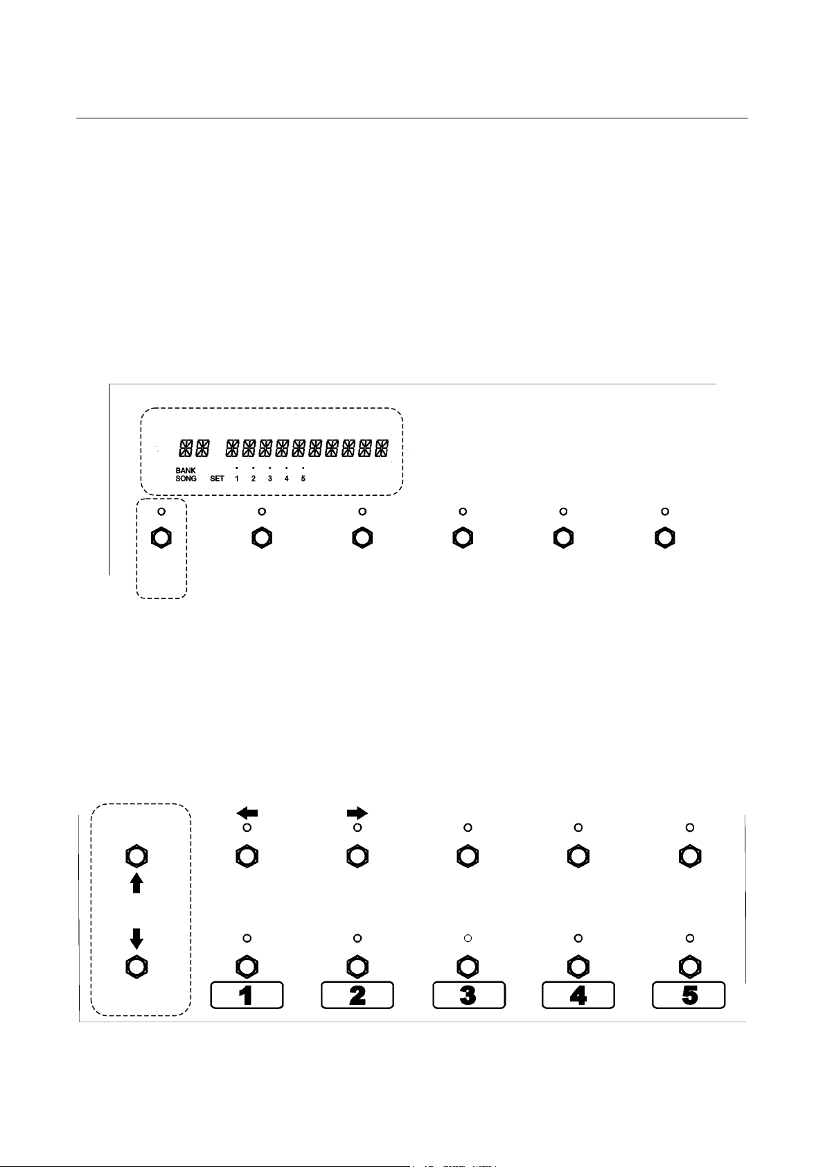
The SC-1 utilizes a total of 125 presets divided into 25 banks containing 5 presets each.
Each preset is capable of storing all MIDI program change and controller change data
programmed (See section 9 to learn how to set up the MIDI data)
Each bank/preset has it’s own 12-character display – divided in two sections – one 2character display and one 10-character display.
The 2-character display will show the bank number, and the 10-character display will show the
unique title of each preset (See section 12).
SKRYDSTRUP R&D
SC-1 System Controller
UP
BANK
SONG
The 5 presets in each bank are selected via the numbered switches 1 through 5.
To increment a bank, press the up
To decrement a bank, press the down
Continued depression of either of these switches will result in repetitive accelerating
incremented or decremented operations.
As you change banks, the bank will not be selected until a preset number is selected.
In other words, you are able to scroll through the 25 banks, and nothing will be recalled unless
one of the numbered switches 1 through 5 is selected.
C6 C7 C8 C9 C10
“” arrow switch.
“” arrow switch.
DOWN
15
Page 16
SC-1 System Controller Manual
9. Song mode
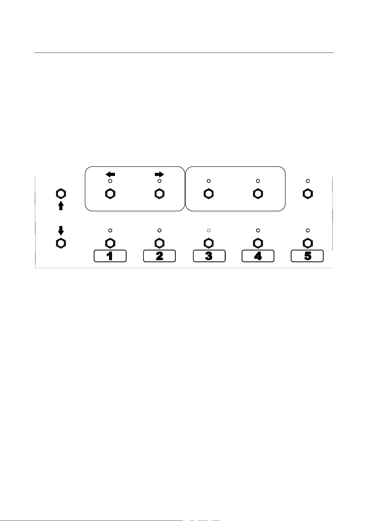
In SONG mode the particular information stored in each of the 125 presets, can be arranged
in any desired order, for access and recall during the performance of SONGS. Each SONG
can contain up to 5 presets.
SET MODE
C1 C2 C3 C4 C5
EDIT SONG/SET
9.1 Accessing the song mode.
To enter the SONG mode, press 2
Using the up
Select SONGS.
Press 2
The display will now show the song number and the title of the song.
“” arrow or the down “” arrow you can scroll through the available modes.
nd
to exit the programming.
nd
then the SET MODE switch.
16
Page 17
SC-1 System Controller Manual
8.2 Modifying a song
You can create up to 99 songs, each with their own unique title.
Select the song number (1-99) you wish to modify.
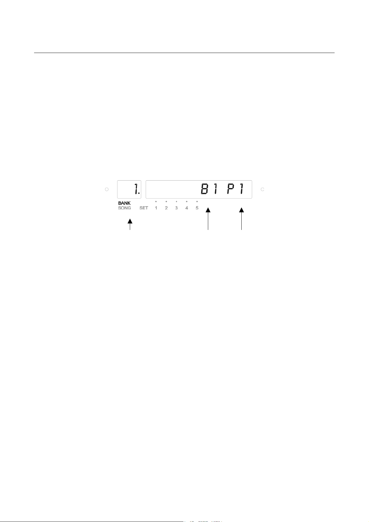
Now, press 2
The display will now show the preset number (1-5) within the selected song in the 2-character
display, and the bank and preset number of the presets actual origin in the 10-character
display.
nd
and then the EDIT SONG/SET switch.
Preset #
(1-5)
Bank #
(1-25)
Preset #
(1-5)
When you have entered the original bank and preset number for preset 1 in this song, press
ENTER to store the values modified.
Move on to preset number 2 in this song, by moving the decimal point to the preset number in
the 2-character display, and via the up
Now modify the original bank and preset number as preferred.
Repeat this procedure for preset 3, 4 and 5, if desired.
“” arrow select preset 2.
HINT! To ensure that it is the correct bank-preset selected, the unique title of the original bank-
preset can be displayed by pressing the C5 switch.
17
Page 18
SC-1 System Controller Manual
10. Set mode
Once you have created the songs you want to use, you are able to organize the songs into 5
different set lists, each containing up to 50 songs.
10.1 Accessing the set mode.
To enter set mode press 2
Using the up
Select i.e. SET 1.
10.2 Editing the set.
Now, press the EDIT SONG/SET switch.
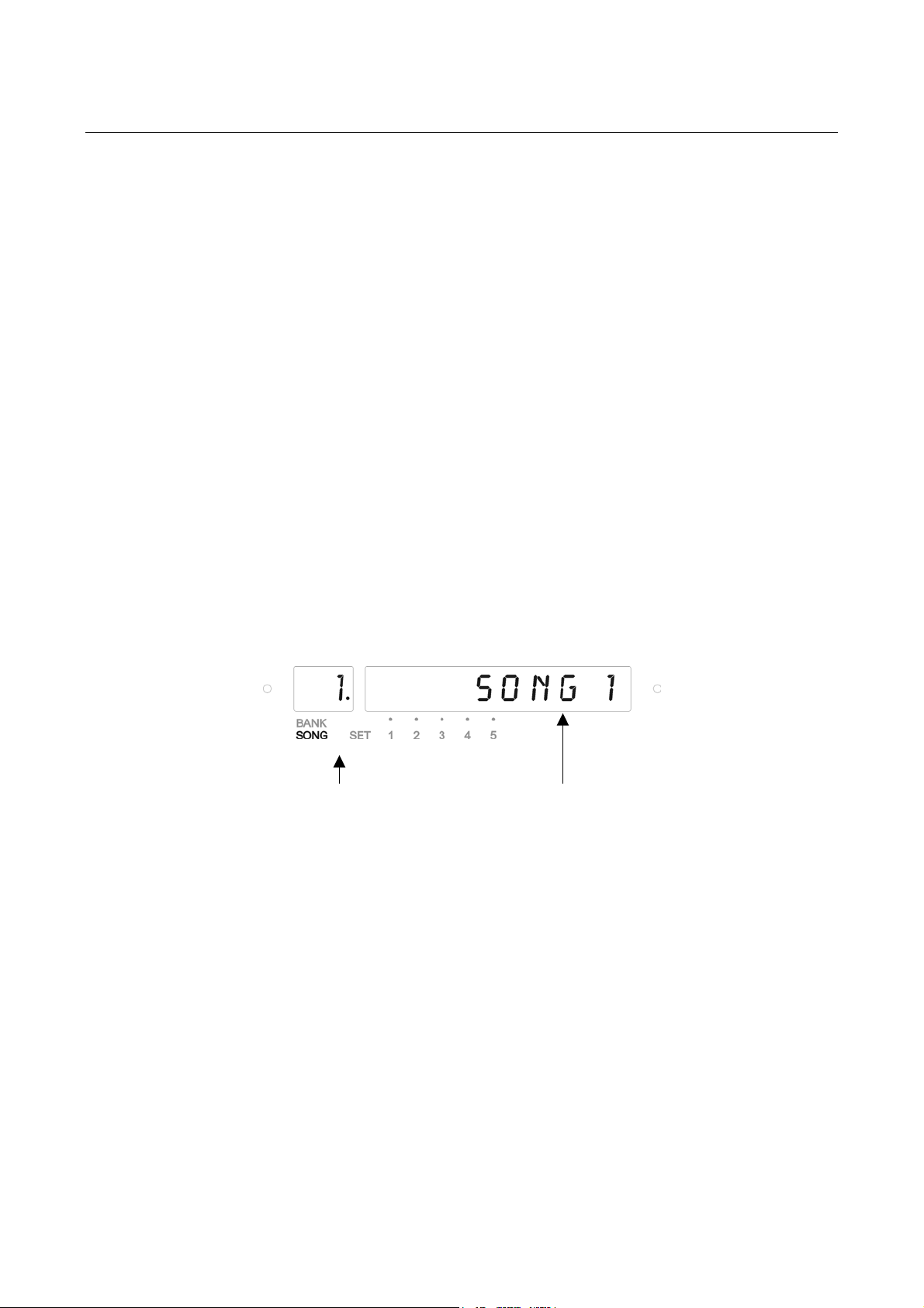
The 2-character display will now show the song number (1-50) within the actual set, and the
original song number is shown in the 10-character display.
Using the right
up
“” arrow or the down “” arrow you can scroll through the 99 songs available.
“” arrow or the down “” arrow you can scroll through the available modes.
“” arrow you can move the cursor to the 10-character display, and with the
nd
then the SET MODE switch.
To specify song # 2 in the set list, use the left “” arrow to place the cursor in the 2-character
display. Use the up
cursor to the 10-character display, and with the up
the original song number or title.
Repeat this procedure until you have created the set list desired.
If you want to organize set list 2-5, press SET MODE switch and choose the set list you want
to modify. Repeat the procedure described above.
HINT! While in the EDIT SONG/SET menu press the C5 switch to view the actual title of the song
selected.
Song # (1-50)
within set.
Original song #
(1-99)
“” arrow to select song # 2. Use the right “” arrow to move the
“” arrow or the down “” arrow, select
18
Page 19
SC-1 System Controller Manual
When you are done, press 2
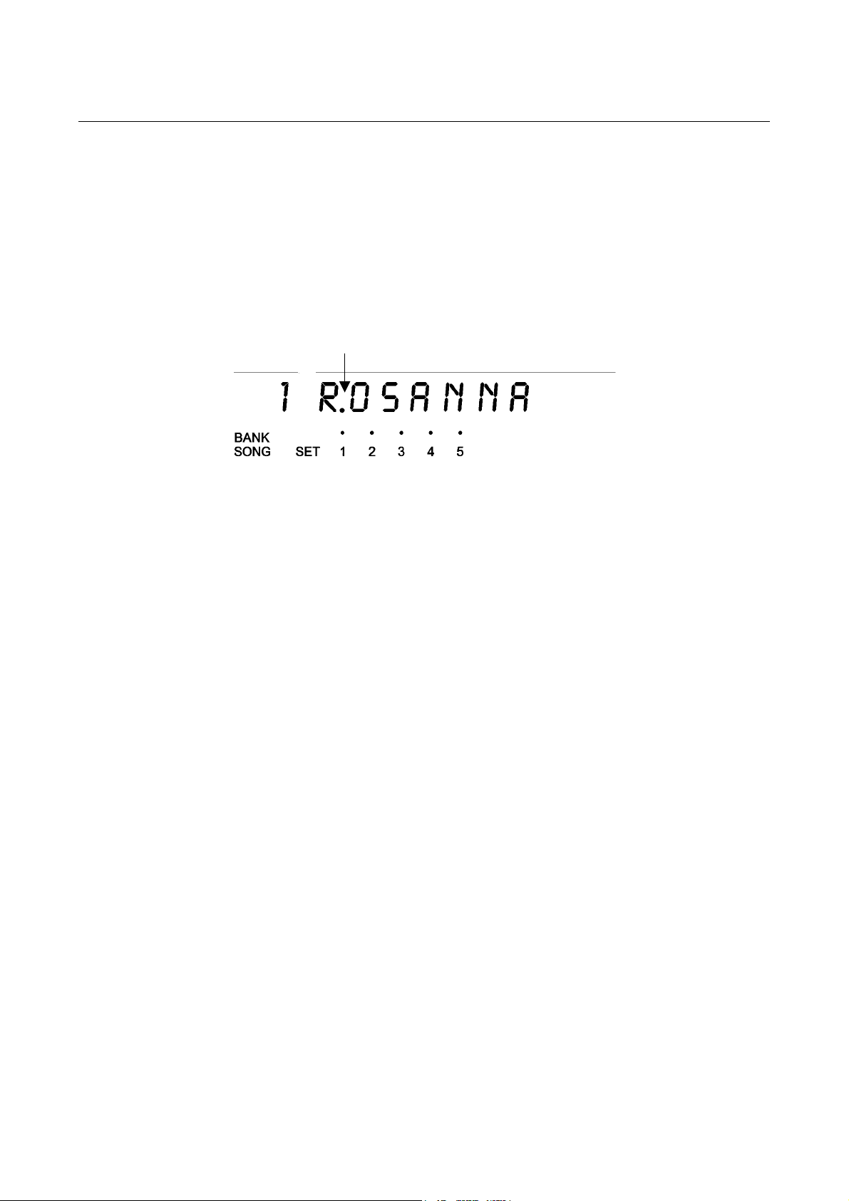
In the 10-character display a dot will indicate which set is active.
nd
to exit.
Indicates set 1
is active
19
Page 20

SC-1 System Controller Manual
11. MIDI menu
MIDI menu is where all MIDI data is programmed.
The MIDI menu is available only in preset mode.
Options available:
• PROGRAM CHANGE Define program change commands.
• CONTROLLER Define CC# and MIDI channel for each controller switch.
• PEDALS Define CC# and MIDI channel, as well as specific pedal value
for each controller port.
Press 2
11.1 PROGRAM CHANGE menu
To send MIDI program change messages, enter PROGRAM CHANGE mode.
Program change commands can be defined for every midi channel in every preset.
The 2-character display shows the MIDI channel. You can scroll through all 16 channels by
using the up
Use the left “” arrow or the right
display and the sections available in the 10-character display.
The 10-character display shows the program change message you want to send on the
selected MIDI channel – displayed in the 2-character display. You can send message 1-128
or OFF.
All values entered are stored in real time.
SC-1 is able to send program change messages and control change information on each of
the 16 MIDI channels simultaneously.
In the example shown below Midi channel 1 is set for program change 42.
Use the left “” arrow to step back to the MIDI menu or 2
preset.
nd
then MIDI switch to enter the MIDI menu.
“” arrow or the down “” arrow.
“” arrow to move the cursor between the 2-character
nd
switch to go back to the current
20
Page 21
SC-1 System Controller Manual
11.2 CONTROLLER menu
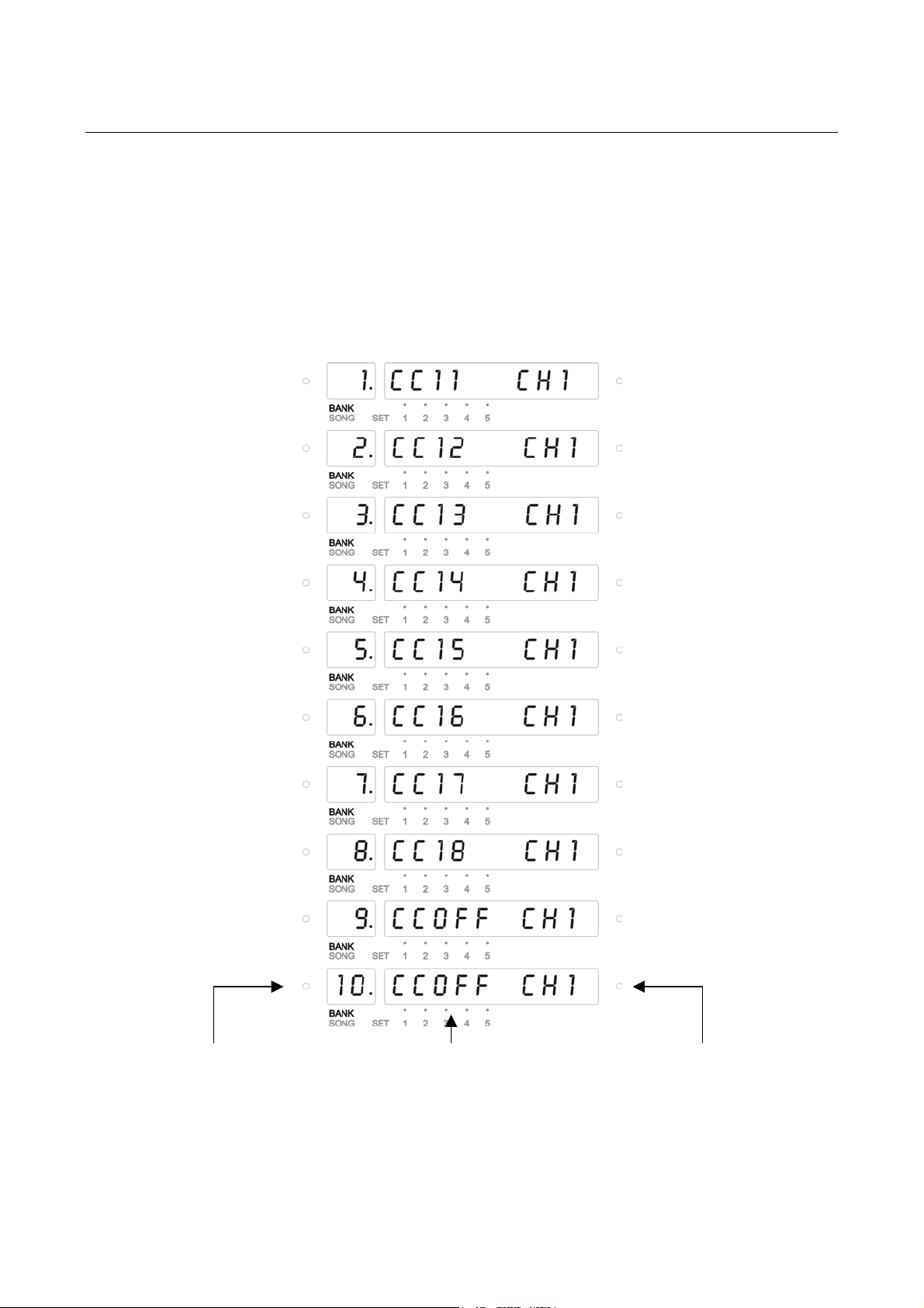
This menu is used for modifying the Control Change type and MIDI channels of the C1 – C10
controllers. These settings are global and cannot be different for every preset.
In the CONTROLLER menu the 2-character display shows the switch number.
I.e. 1 equals C1, 2 equals C2 and so on.
In the 10-character display you set the CC number and the MIDI channel.
Factory default is MIDI control change (CC) numbers that matches our MR8 Loop System.
If you are using a different Loop System or unit you want to control via control change, refer to the owner’s manual of the
device you need to control, for MIDI control change numbers and channel.
Switch # (1-10) MIDI channel (1-16)
MIDI Control Change #
(0-127, OFF)
21
Page 22
SC-1 System Controller Manual
11.3 PEDALS menu
Options available:
• PEDAL CC
• PEDAL GLOBALS
• PEDAL VALUE
PEDAL CC
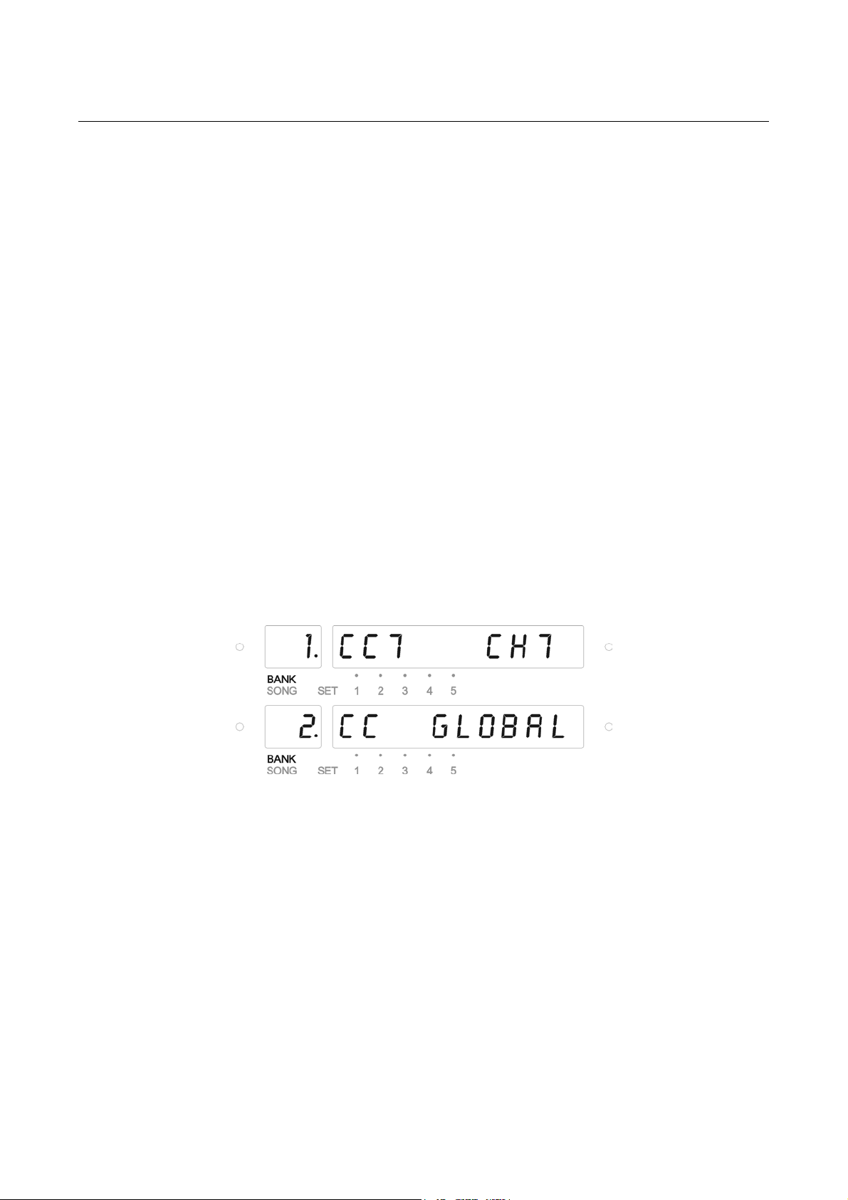
In PEDAL-CC menu your options are OFF, GLOBAL or a specific MIDI CC number and MIDI
channel for P1/P2.
If you choose GLOBAL, the settings will be as programmed in the PEDAL GLOBAL menu.
If you choose a different MIDI CC number and MIDI channel, the global settings will be
ignored.
The editing procedure works exactly like in Controller Mode. The 2-character display now
shows the pedal number.
22
PEDAL GLOBALS
In PEDAL GLOBALS menu you set the global MIDI CC and MIDI channel for P1/P2.
These settings are global, but they can be ignored by the settings in the PEDAL-CC menu.
The global setting is intended to use for the predominant setting.
If you i.e. primarily use P1 for controlling a certain parameter (i.e. master volume) you
program the pedal settings needed for this specific operation.
Page 23
SC-1 System Controller Manual
The editing procedure works exactly like in Controller Mode. The 2-character display now
shows the pedal number.
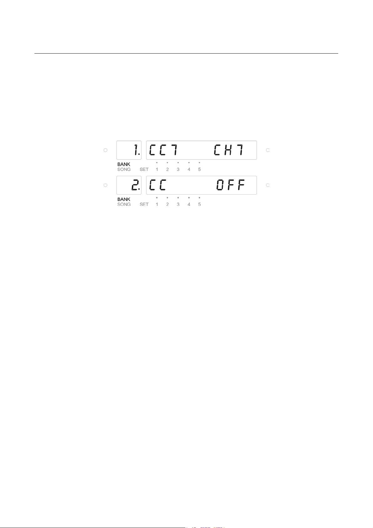
Example:
In the example shown Pedal 1 is set for control change 7 – midi channel 7.
Pedal 2 is set for off.
Again, use the left “
sections available, and use the up
section selected.
” arrow or the right “” arrow is to move the cursor between the
“” arrow or the down “” arrow to change value in the
PEDAL VALUE
PEDAL-VALUE is a feature never seen in a MIDI board before. This feature enables you to
store specific pedal values in each preset. When using a MIDI controllable VCA, or any multi
efx machine (like the TC Electronic G-Force) with a MIDI controllable volume, you will i.e. be
able to program specific volume levels or any specific control change value in each preset.
• You have a MIDI controllable VCA like i.e. the Rocksonics MVCA-4.
• Set the MIDI channel on the VCA for i.e. channel 7. Volume is controlled on CC# 7.
• Press 2
• Use the up “
• Press ENTER or right “
• Use the up “
• Press ENTER or right “
• Use the up “
nd
then MIDI.
” arrow or down “” arrow to select the PEDALS menu.
” arrow.
” arrow or down “” arrow to select the GLOBALS menu.
” arrow.
” arrow or down “” arrow to alternate between P1 and P2.
23
Page 24

SC-1 System Controller Manual
• Press the right “
• Set i.e. pedal 2 for CC7 (control change number 7) and CH7 (MIDI channel 7).
The VCA and the SC-1 will now be able to communicate.
• Use the left “
• Use the up “
• Use the up “
The 2-character display should read 2 (pedal 2).
• Now, enter the PEDAL-VAL menu and by using the up arrow or the down arrow
• Use the right “
default value is 127 (max.). By using the up “
expression pedal connected to P2 – you can now alter the value. Settings possible is
anywhere between 0 (min.) and 127 (max.). This way you can pre-program any volume
levels needed for your performance, in every preset.
” arrow.
” arrow to return to where the display reads GLOBL.
” arrow or down “” arrow to select the VALUE menu.
” arrow or down “” arrow to select pedal 2.
” arrow is to move the cursor to the 10-character display. The factory
” arrow or down “” arrow, or the
24
Page 25

SC-1 System Controller Manual
12. TITLES menu
After the bank-preset or song has been selected, titles for bank-presets and songs can be
entered or modified by pressing 2
The decimal point is blinking next to the character to be entered or modified.
Move the decimal point by using the left “” arrow or right
The selected character can be altered using the up “” arrow or down “” arrow.
HINT! If you want to delete the entire title, simply press the C5 switch.
nd
, and then the TITLES switch.
“” arrow.
25
Page 26

SC-1 System Controller Manual
13. COPY menu
The copy menu allows you to copy …
• a bank-preset into another bank-preset.
• a song into another song.
This menu is available only in preset and song modes.
13.1 To copy a bank-preset into another bank-preset:
1. Select the bank-preset you wish to copy.
2. Press 2
3. The cursor is blinking next to the bank number. By using the up
arrow select the desired bank (1-25) number you wish to copy into.
4. By using the right
“” arrow or down “” arrow select the desired preset number (1-5) you wish to copy
into.
5. Press ENTER to store the copy.
6. Press 2
13.2 To copy a song into another song:
1. Select the song you wish to copy.
2. Press 2
3. The cursor is blinking next to the song number. By using the up
arrow select the desired song (1-99) number you wish to copy into.
4. Press ENTER to store the copy.
5. Press 2
nd
, and then COPY.
“” arrow the cursor will move to the preset number. By using the up
nd
to exit programming.
nd
, and then COPY.
nd
to exit programming.
“” arrow or down “”
“” arrow or down “”
26
Page 27

SC-1 System Controller Manual
14. System menu
The SYSTEM menu is used for MIDI Bulk functions, general information on software; restore
functions as well as calibration of expression pedals.
Options available:
• MIDI BULK Bulk Dump, Bulk Load and Device ID.
• VERSION Indication of software version.
• RESTORE Restore to factory default.
• PEDALS Calibrate your expression pedals, select Grab function and
select type of pedal connected to P1/P2.
• GLOBAL PR Determines if the Global Preset should be ON or OFF.
14.1 MIDI BULK
DUMP
Enables you to dump data stored in the SC-1 as sysEx data, to i.e. your computer. This menu
contains the following options:
• DUMP ALL Dump all data. Press ENTER to instantly start dumping all data.
• DUMP PSET Dump one or all presets. Press ENTER and select all or bank
and preset number by using the arrows.
Start dumping by pressing ENTER.
• DUMP SONG Dump one or all songs. Like DUMP PSET.
• DUMP SET Dump one or all sets. Like PUMP PSET.
• DUMP GLOB Dump global data (controller and pedal settings). Press ENTER
to dump global data.
Use the left “” arrow to step back to the previous menu.
LOAD
Enables you to load any sysEx data previously dumped. The sysEx data can be sent to the
SC-1 at any time, but it is recommended that you use this function for that purpose.
14.2 VERSION
Displays the software version on your SC-1. Software updates can be downloaded on
http://www.skrydstrup.com
27
Page 28

SC-1 System Controller Manual
This procedure will permanently erase all user settings!
14.3 RESTORE
Restore to factory default. ALL, PRESET, SONG, SET or GLOBALS can be selected.
ALL – means that all settings in the SC-1 will be restored to factory default.
PRESET – means that all presets will be restored to factory default.
SONG – means that all songs will be restored to factory default.
SET – means that all sets will be restored to factory default.
GLOBALS – means that all global data will be restored to factory default.
• Press 2
• Use the up “” arrow or down “” arrow to select RESTORE menu.
• Press ENTER or right “” arrow.
• Use the up “” arrow or down “” arrow to select the type of restore required.
• Press ENTER to confirm the restore procedure.
14.4 PEDALS
CALIB PDLS (abbreviation for Calibrating Pedals)
Enables you to specify the minimum and maximum point of your expression pedals to the
SC-1. This ensures best possible performance.
• Press 2
Use the up “” arrow or down “” arrow to select CALIB PDLS menu.
• Press ENTER or right “” arrow.
• Use the up “” arrow or down “” arrow to alternate between P1 and P2.
• Press ENTER or right “” arrow.
The 10-character display now reads MINIMUM.
• Place the pedal at its minimum point, and press ENTER.
The 10-character display now reads MAXIMUM.
• Place the pedal at its maximum point, and press ENTER.
You have now calibrated your pedal. Repeat procedure for the second pedal if necessary.
nd
then SYSTEM.
nd
then SYSTEM.
WARNING!
28
Page 29

SC-1 System Controller Manual
PEDL SCALE
Enables you to specify the type of pedal used in P1/P2.
Possible values are…
• PDL LIN (Pedal Linear) for linear taper of the expression pedal.
• PDL LOG (Pedal logarithmic) for audio/logarithmic taper.
• PDL MOM (Pedal Momentary) for momentary footswitch.
• PDL LATCH (Pedal Latching) for latching footswitch.
Selecting the logarithmic taper will try to make a audio/logarithmic taper act like a linear one.
When using a momentary or latching switch for control change functions, PDL MOM (Pedal
Momentary) should be selected.
The factory setting for these parameters is PDL LIN (Pedal Linear).
• Press 2
• Use the up “”or down “” arrow to select PEDL SCALE menu.
• Press Enter or right “” arrow.
• Use the up “”or down “” arrow to alternate between P1 and P2.
• Press Enter or right “” arrow.
• Use the up “”or down “” arrow to select the scale required.
• You do not need to press ENTER to store the settings.
nd
then SYSTEM.
14.5 GLOBAL PRESET
GLOBAL PR (abbreviation for Global Preset)
Enables you to specify if the Global Preset feature should be ON or OFF.
Use the up “”or down “” arrow to select the status.
(abbreviation for Pedal Scale)
29
Page 30
SC-1 System Controller Manual
15. Cables
If you want to use the ports P1/P2 on the SC-1, it is important to use proper cables.
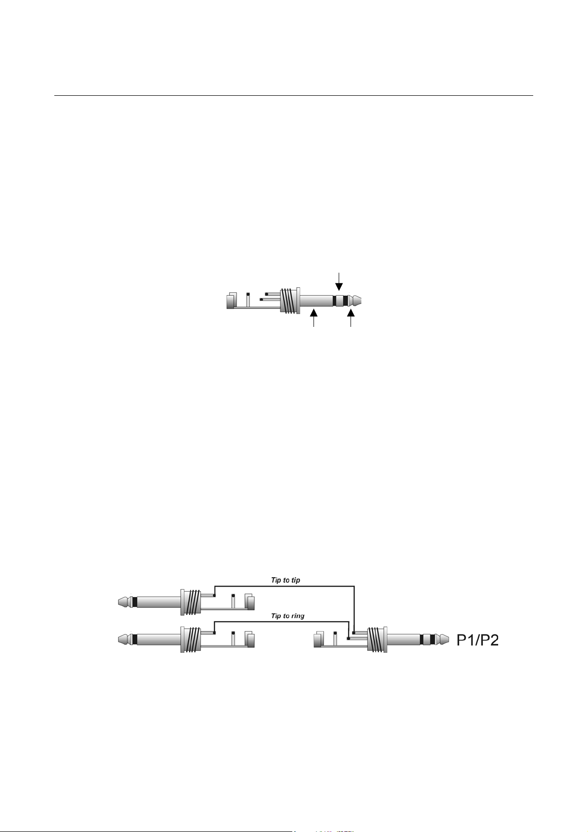
P1/P2 uses a standard ¼” TRS stereo jack, and is configured as follows:
TIP is pedal input
RING is pedal output
SLEEVE is ground.
RING
The ring of this jack is internally wired to +5V through a 200 Ohm resistor, so that external
short circuits will not damage the unit.
GND
15.1 USING AN EXTERNAL EXPRESSION PEDAL
A standard ¼” TRS stereo jack cable provides connection for an external expression pedal,
like the Boss FV300L pedal.
15.2 USING AN EXTERNAL VOLUME PEDAL
A ¼” TRS stereo jack cable into 2 x ¼” mono jack cable provides connection for an external
volume pedal, like the Ernie Ball 6166 volume pedal.
The cable should be configured as the drawing shown below.
TIP
Input
Output
15.3 USING AN EXTERNAL SWITCH
A standard ¼” mono jack cable provides connection for an external momentary switch, like
the Boss FS-5U.
30
Page 31

SC-1 System Controller Manual
16. MIDI Implementation Chart
Model: SC-1 System Controller Version: 1.2 Date: May 2002.
Function Transmitted Recognized Remarks
Basic
Channel Changed 1-16
Default X X
Mode Messages X X
Altered X X
Note Number True Voice X X
Velocity Note On X X
Note Off X X
After Touch Key’s X X
Channel X X
Pitch Bend X X
Control Change 0-127, off O X
Program Change True Number O X Programs 1-128
System Exclusive O O
Song Position X X
System Common Song Select X X
Tune Request X X
System Real-Time Clock X X
Commands X X
Local On/Off X X
Aux. Messages All Notes Off X X
Active Sensing X X
System Reset X X
X: NO O: YES
Default
1-16
1-16
31
 Loading...