

SKP Pro Audio VZ-40 A, VZ-60A User Manual
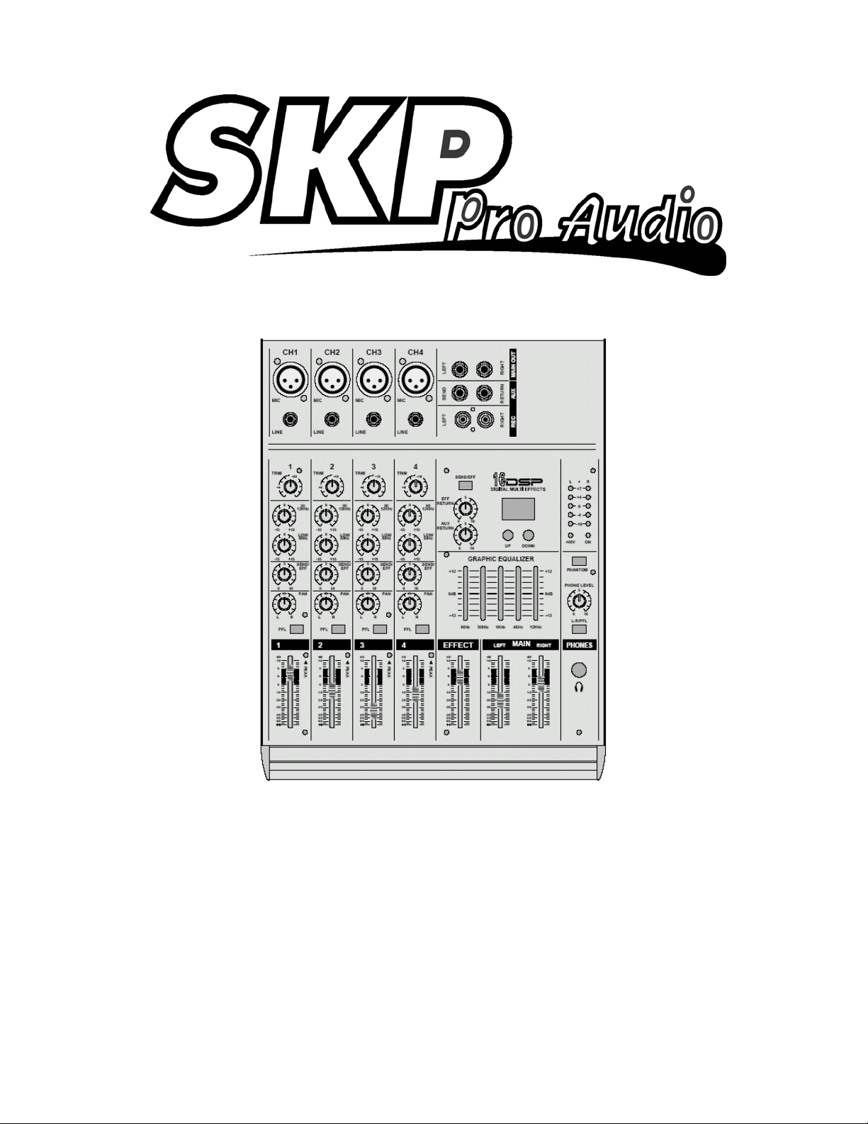
VZ-40 A / VZ-60A
4 - 6 CHANNEL
MIC/LINE MIXER

A. INPUT CHANNEL SECTION
2
B. MASTER SECTION
C. MIXER OUTPUT SECTION
D. POWER SECTION
E. INSTALLATION
F. APPENDIX
G. BLOCK DIAGRAM
3~4
5
6
6
7
8
Ultra-low noise discrete Mic Preamps with +48 V Phantom Power
Extremely high headroom - offering more dynamic range
Balanced Inputs for highest signal integrity
Ultra-musical 2-band EQ on all channels
Peak LEDs all Mono Channels
1 Aux Send per channel for external effects and monitoring
Build in digital multi (16 DSP)
Master Mix Output and rec output
Highly accurate 5 segment Bargraph Meters
Separate Master Mix Outputs
SAFETY INSTRUCTIONS
CAUTION:
WARNING:
To reduce the risk of electrical shock, do not remove
the cover (or back). No user serviceable parts inside;
refer servicing to qualified personnel.
To reduce the risk of fire or electrical shock, do not
expose this appliance to rain or moisture.
This symbol, wherever it appears, alerts
you to the presence of uninsulated
dangerous voltage inside the enclosure
- voltage that may be sufficient to constitute a risk of shock.
CAUTION
RISK OF ELECTRIC SHOCK
DO NOT OPEN
This symbol, wherever it appears, alerts
you to important operating and maintenance instructions in the accompanying
literature. Read the manual.
1
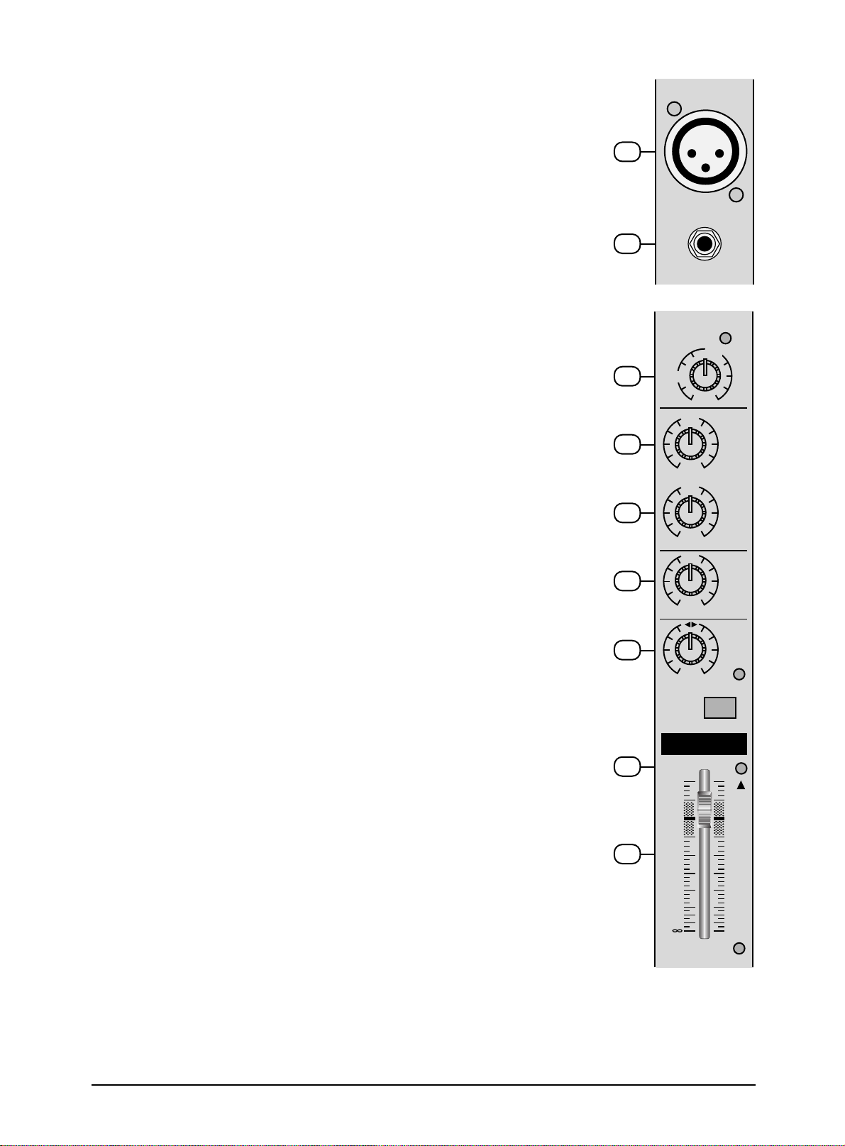
A. INPUT CHANNEL SECTION
1. BALANCE INPUT (MIC)
Electronially Balanced inputs acceptable a standard XLR male connector.
+ 48V Phantom Power available on each input Mic socket.
and this switch is on Rear Phantom Power.
2. LINE INPUT
The unbalanced Mic input is provided for the use of an unbalance mic and is
designed to accept an unbalanced high impedance input signal.
(This use for connection Deck, Turntable, Keyboard etc..)
CH1
1
MIC
2
LINE
3. TRIM
This has a function which adjusts the input sensitivity of each channel in order
to input the constant level of the signal.
4. HI EQ
This control gives you up to 15 dB of boost or cut at 12KHz and above, and it is
also flat at the detent. Use it to add sizzle to cymbals, and an overall sense of
transparency or edge to key-boards, vocals, guitar, and bacon frying. Turn it
down a little to reduce sibilance, or to hide tape hiss.
5. LOW EQ
This control gives you up to 15 dB boost or cut at 80Hz and below. This circuit
is flat (no boost or cut) at the center detent position.
This frequency reptesents the punch in bass drums, bass guitar, fat synth
patches, and some really serious male singers.
6. SEND /EFF
This is normally derived after the EQ and channel fader (POST FADE, POST
EQ), and is therefore follow any changers in fader level. They are normally
used to drive effects processing units which are fed back into the mixer and
which must fade out with the input channel.
1
TRIM
3
4
5
6
7
+4
PFL
-
10
0
HI
12KHz
+15-15
0
LOW
80Hz
+15-15
5
SEND/
EFF
100
PAN
RL
7. PAN
The pan control sends continuously variable amounts of the post fader signal to
either the left and right main busses. In the center position equal amounts of
signal are sent to the left and right.
8. CHANNEL FADER
This is function to adjust the volume of signal connection into each channel and
adjust the volume of output, together with master fader. Normal operating
position is at the “O” mark, providing 4dB of gain adove that point, if required.
9. PEAK
A red LED indicates a signal level at the insert return point, premaster fader, It
illuminates at approximately 5dB below clipping.
2
1
9
8
dB
10
5
0
5
10
20
30
40
50
60
PEAK
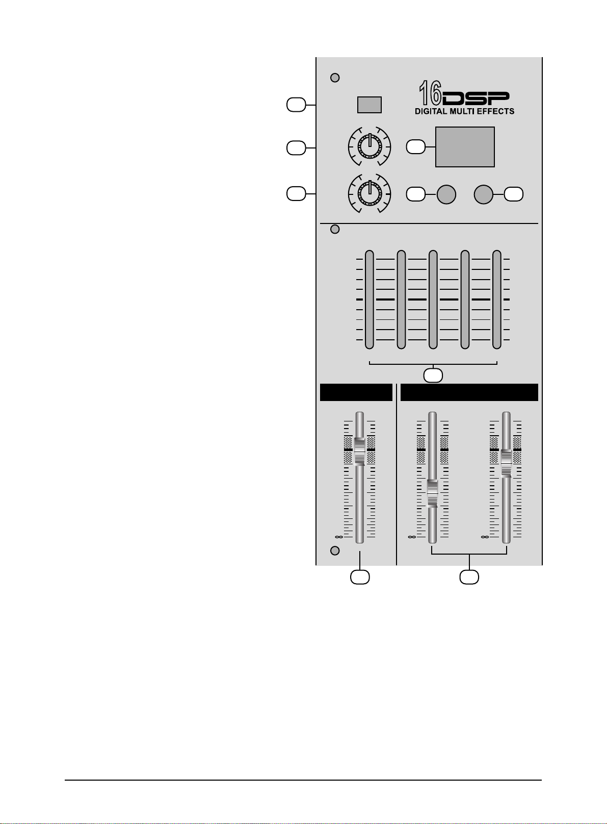
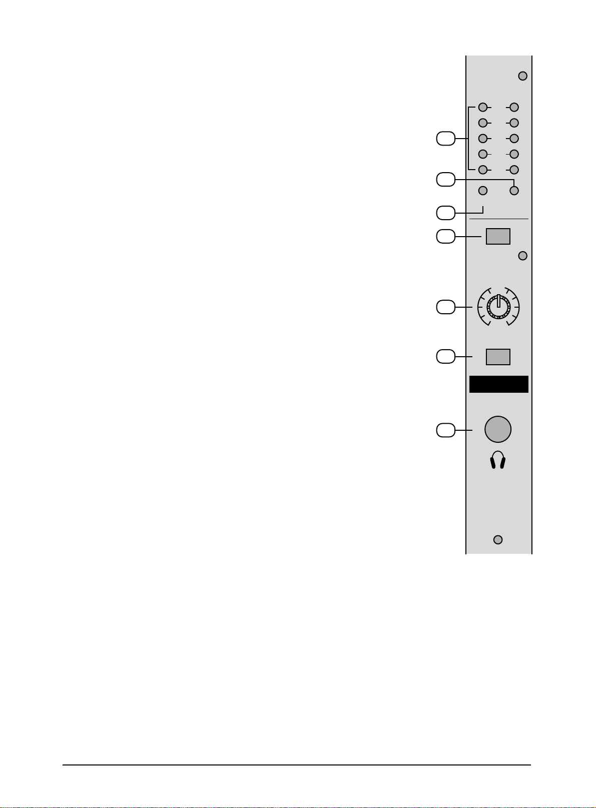
B. MASTER SECTION
10. SEND / EFFECT
When this button is up, Post signal work
as send signal.
When this button is down, post signal
work as EFFECT singal.
11. EFFECT RETURN
This is used for adjusting frequency of
echo repeat, since too echo repeat may
cause a nowl, please adjust frequency
properly.
12. AUX RETURN
This is used for adjusting frequency of
echo repeat, since too echo repeat may
cause a nowl, please adjust frequency
properly.
13. EFFECT PROGRAMS
When adjust switch 19,20,21,22 ,ore
effects are displayed.
14. UP TAPE SWITCH
One push, one program up, push with
more than 5 swconds.
15. DOWN TAPE SWITCH
One push, one program down, push with
more than 5 swconds, hi-speed program
down.
16. EFFECT LEVEL
Using by this control, you can adjust
signal level of echo repeat & exteral effect.
10
11
12
SEND/EFF
EFF
RETURN
AUX
RETURN
+12
0dB
-
12
EFFECT
dB
10
5
0
5
10
20
30
40
50
60
5
13
10
0
5
14 15
10
0
UP DOWN
GRAPHIC EQUALIZER
80Hz 350Hz 1KHz 4KHz 12KHz
17
LEFT RIGHT
dB
10
5
0
5
10
20
30
40
50
60
MAIN
dB
10
5
0
5
10
20
30
40
50
60
+12
0dB
-
12
17. STEREO GRAPHIC EQUALIZER
2X5-band equalizer is provided for tone
control over each frequency, and for
precise high quality sound by final tone
control.
18. OUTPUT MAIN FADER
(LEFT/RIGHT)
This is a master fader for adjustment for
volume of left/right output. Unity gain is
the top their travel.
16 18
3
19. OUTPUTS LEVEL INDICATOR
This is level meter which shows output levels of left & right channel
condition on the way of operation, therefore, you can see output
condition thru this master level indication.
20. POWER LED
The POWER LED will be turned on when strt working.
21. PHANTOM LED
The LED will be turned on when strt working.
19
20
+L R
+7
+4
0
-4
-10
22. PHANTOM POWER SWITCH
Depressing this switch applies 48V DC across all microphone input
channels connectors for remote powering of condenser microphones.
23. HEADPHONE LEVEL
This is a single volume control sends the level to be the headphones
and main monitors.
24. HEADPHONE SWITCH
When L-R/PFL switch up, could monitor stereo (L-R) output signal when
L-R/PFL switch down, could monitor group (PFL) output signal.
25. HEADPHONE JACK
You can monitor working condition by sound thru the headphone.
21
22
23
24
25
+48V ON
PHANTOM
PHONE LEVEL
5
10
0
L-R/PFL
PHONES
4
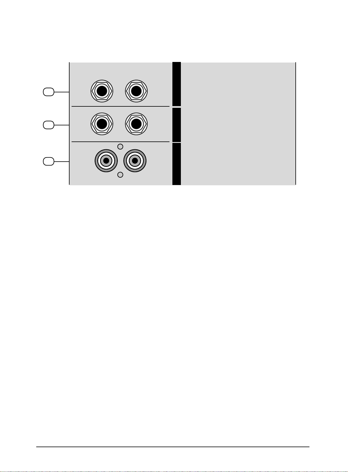
C. MIXER OUTPUT SECTION
26
27
28
LEFT
SEND
LEFT
RIGHT
RETURN
RIGHT
REC AUX MAIN OUT
26 MAIN OUTPUT JACK (LEFT / RIGHT)
In this product, the final confirmed sound can be send to main amplifier through jack.
27. AUX SEND/RETURN JACK
This can be used to connect all kinds of effect form outside.
28. RECORD PIN JACK
This jack is to be connected with cassette deck when recording the mixed output.
5
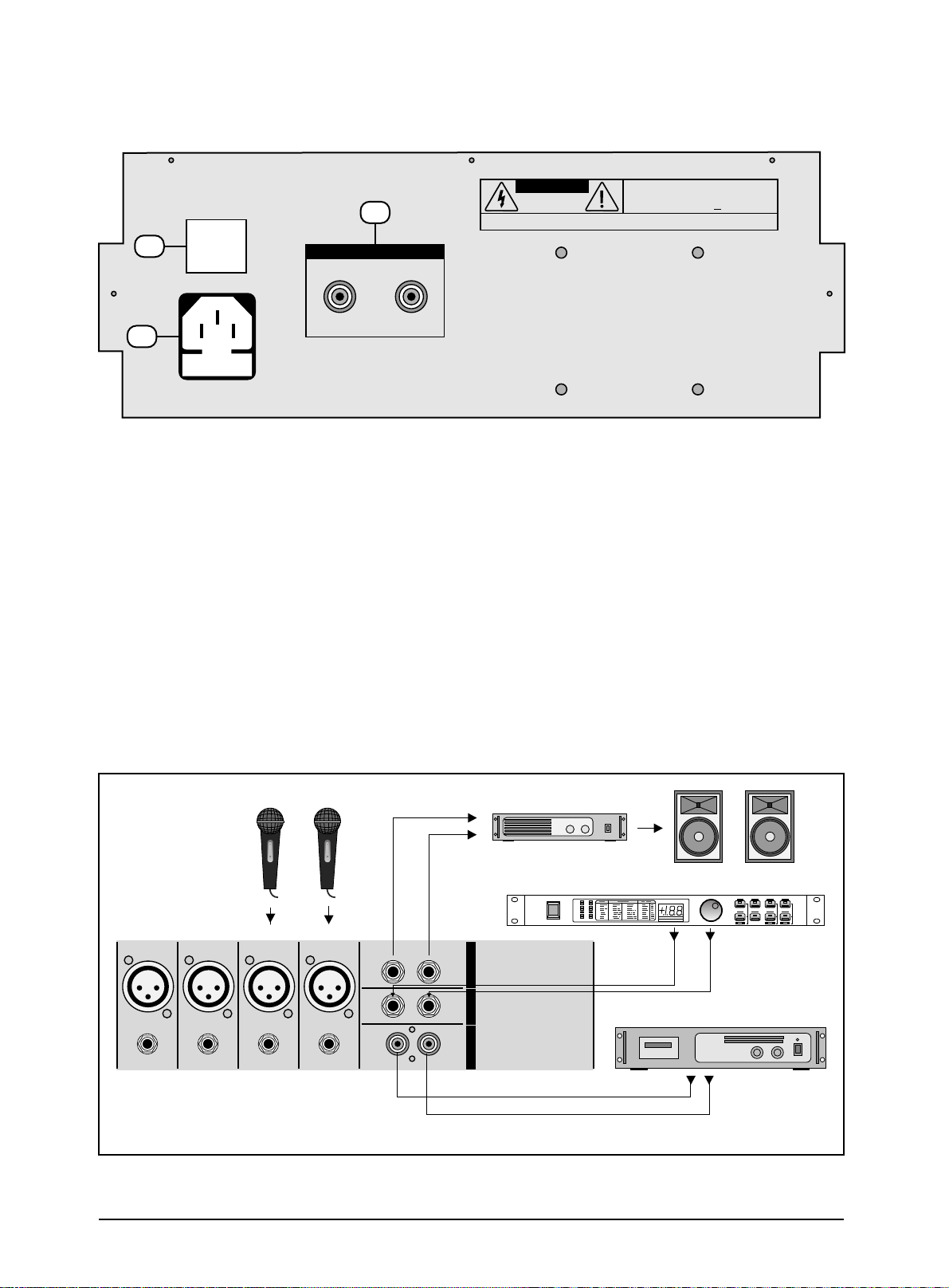
D. POWER SECTION
30
29
POWER
31
SPEAKER OUTPUTS
2@100W 4Ω
RIGHT
LEFT
CAUTION
RISK OF ELECTRIC SHOCK
DO NOT OPEN
REPLACE WITH THE SAME TYPE FUSE AND RATING.
CAUTION:
DISCONNECT SUPPLY CORD BEFORE CHANGING FUSE.
WARNING:
TO REDUCE THE RISK OF FIRE OR ELECTRIC SHOCK. DO NOT
EXPOSE THIS EQUIPMENT TO RAIN OR MOISTURE. DO NOT REMOVE COVER.
NO USER SERVICEABLE PARTS INSIDE. REFER SERVICING TO QUALIFIED PERSONNEL.
RISQUE DE CHOC ELECTRIQUE NE PAS OUVRIR
AVIS:
UTILISE UN FUSIBLE DE RECHANGE DE MÊME TYPE.
ATTENTION:
DEBRANCHER AVANT DE REMPLACER LE FUSIBLE.
AC IN / FUSE
29. POWER SWITCH
Push marked (1), when you want to operate. The LED (SEE NO, 33) will be turned on when working
30. POWER JACK
This is out of connect the power supply (2 X AC 120V or 230V) jack.
31. SPEAKER JACK
This is same functions as below but the using jack is different.
E. INSTALLATION
Experience tells us that the cables in a studio environment get tangled very quickly (inviting mistakes).
MIC
LINE
CH1
MIC
LINE
CH2
MIC
LINE
CH3
MIC
LINE
CH4
LEFT
SEND
LEFT
RIGHT
RETURN
RIGHT
REC AUX MAIN OUT
MODEL-DVP-3000
AMPLIFIER
DIGITAL
+6
+3
01
09
02
10
+1
03
11
0
04
12
05
13
-1
06
14
-3
07
15
-6
08
16
L RdB
POWER
SURROUND
17
25
18
26
19
27
20
28
21
29
22
30
23
31
24
32
TAPE
OUTPUT
L & R
6

F. APPENDIX
Specifications
Mono Inputs
Mic Input
Bandwidth
Distortion (THD & N)
Mic E.I.N (22 Hz - 22 kHz)
TRIM range
Line Input
Bandwidth
Distortion (THD&N)
Line level range
Equalization
Hi Shelving
Lo Shelving
Master Mix section
Max Output
Aux Send Max Out
Control Room Out
Signal-To-Noise Ratio
Power supply
electronically balanced, discrete input configuration
10 Hz to 60 kHz ± 3 dB
0.01% at +4 dBu, 1 kHz, Bandwidth 80 kHz
-129.5 dBu, 150 Ohm source
-117.3 dBqp, 150 Ohm source
-132.0 dBu, input shorted
-122.0 dBqp, input shorted
+10dB to +60dB
electronically balanced
10 Hz to 60 kHz ± 3 dB
0.01% at +4 dBu, 1 kHz, Bandwidth 80 kHz
+10 dBu to -40 dBu
12 kHz +/-15 dB
80 Hz +/-15 dB
+22 dBu balanced
+22 dBu unbalanced
+22 dBu unbalanced
112 dB, all channels at Unity Gain
Mains Voltages
Power 4CH
VZ-40 110/220V~60/50Hz 400W Clase I
VZ-60 100/220V~60/50Hz 300W Clase I
2X150W(4 )
6CH
2X200W(4 )
7
 Loading...