

SKP Pro Audio VZ-12USB, VZ-16USB Operating Manual
VZ-12USB / VZ-16USB

FEATURES:
Four XLR mic inputs on VZ-12USB, Six XLR mic inputs on VZ-16USB
Four stereo channels with 1/4" inputs
Three-band channel EQ
Inserts on all mono channels
80 Hz low-cut switch on every input channel
USB connectivity
Clip LEDs monitor the entire signal path for clipping
Signal LEDs on every input channel
48 Volt phantom power switch
Effects send on every channel with stereo return
Internal digital effects with 16 selections, including reverb, delay and vocal
enhancement
Effect parameter adjustment allows you to customize each effect selection
Monitor send on every channel
Zero latency record monitoring capabilities
Control room output with level control
Contour EQ switch

Important Safety
Instructions
Safety sy mbols used in this p roduct
This symb ol alerts the user that there a re important ope rating and maintenance
instruc tions in the liter ature acc ompanying this u nit.
This symb ol warns the user of uninsula ted voltage with in the unit that can c ause
dangero us electric shocks.
This symb ol warns the user that output connectors cont ain voltages tha t can cause
dangero us electrical shock.
Please fo llow these preca utions when usin g this
product :
1. Read the se instructions.
2. Keep the se instructions.
3. Heed all w arnings.
4. Follow a ll instructions.
5. Do not use t his apparatus ne ar water.
6. Clean on ly with a damp cloth . Do not spray any liquid clean er onto the facepl ate, as this may
damage th e front panel controls or cau se a dangerous con dition.
7. Instal l in accordance with the manu facturer's ins tructions.
8. Do not ins tall near any heat sources su ch as radiators, h eat registers, s toves, or other
apparat us (including amplifier s) that produce he at.
9. Do not def eat the safety pur pose of the polarized or grou nding-type plug. A polarize d plug
has two bla des with one wider than the oth er. A grounding-typ e plug has two blades and a third
groundi ng prong. The wide blade or t he third prong is provided fo r your safety. Wh en the
provide d plug does n ot fit into your out let, consult an el ectrician for re placeme nt of the obsolete
outlet.
10. Prote ct the power cord fr om being wa lked on or pinched , particularly at plugs, co nvenience
recepta cles, and the point where the y exit from the appa ratus.
11. Use only attach ments or accesso ries specified by the manuf acturer.
12. Use onl y with a cart, stand , bracket, or table designe d for use with profe ssional audio or
music equ ipment. In any installati on, make sure that i njury or damage will not resu lt from cables
pulling o n the apparatus and its mount ing. If a cart is used , use caution when m oving the
cart/ap paratus combination to av oid injury from ti p-over.
13. Unplu g this apparatus during lig htning storms or w hen unused for lon g periods o f time.
14. Refer a ll servicing to qualified s ervice personn el. Servicing is required w hen the apparatu s
has been da maged in any way, such as when t he power-supply cord or plu g is damaged,liq uid
has been sp illed or objects have falle n into the apparat us, the apparatus has been exposed to
rain or moi sture, does not op erate nor mally, or has been d ropped.
15. Thi s unit produces heat when ope rated normally. Operate i n a well-ventila ted area with at least
six inche s of clearance from periphe ral equipment.
16. This product , in combination w ith an amplifier a nd headph ones or speakers , may be
capable o f producing sound levels th at could cause permanent he aring loss. Do not o perate for
a long peri od of time at a high volume level o r at a level that is unc omfortable. If you experi ence
any heari ng loss or ringing in the ears, y ou should consul t an audiologist.
17. Do not ex pose the apparatus to dripp ing or splashing . Do not place objects filled w ith liquids
(flower v ases, soft drink c ans, coffee cups) on the ap paratus.
18. WARNING: To reduce the risk of fire or elec tric shock, do not e xpose this apparatus to rain
or moistu re

Using Pro per Cables
When conn ecting instruments and ot her equipment to t he VZ series, it's im portant that you
use the app ropriate types of cables. H ere are some simpl e but important guideline s:
For the mic i nputs, use XLR cab les.
For the lin e inputs and all oth er 1/4” connections, use 1/ 4” mono TRS cable s.
And use ster eo RCA cables for the 2-track in a nd out.
Setting L evels
Before yo u can begin mixing differ ent audio sources with your series, you must se t the level for
each chan nel you're using. This help s to prevent disto rtion and clipping. The i dea is to get the
stronge st signal possible withou t clipping. Here 's how:
1. Turn the ch annel level control to the 12 :00 position.
2. Turn the AUX S END and GAIN controls all the w ay down, and turn th e EQ knobs to the cent er
detent (y ou'll feel a click).
3. Connec t the source of the si gnal to the channel's input .
4. Play the i nstrument at a nor mal level a nd adjust the chan nel's gain slowly until the P EAK LED
lights.
5. Slowly r educe the channel's gain un til the PEAK LED no lo nger lights when you play.
6. If you nee d to apply EQ, do so and c heck the PEAK LED to make sure it s till does not ligh t as
you play.
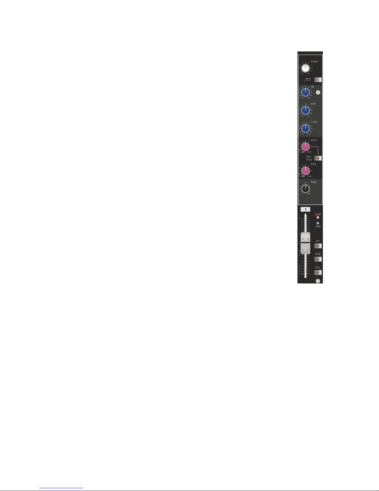
Front Pan el
FADER
Equaliz er
Provide s +/-15dB of control over hig h, mid and low frequ ency rang es at the center
frequen cies listed below.
HIGH : 10kH z (shelving)
MID : 2.5 kHz ( peaking)
LOW : 100Hz ( shelving)
Frequen cy response will be flat when t he knob is positio ned at “0”.
from fader to AUX1
Control s the level of the signal sent fr om each channel to the EFFECT bus.
This cont rol is located after the chan nel fader so its lev el will also be affected by t he
channel f ader setting.When a stere o channel is used, L and R ch annel signals are
combine d and sent to the EFFECT bus.
Trim
This cont rol establishes the nomin al operating lev el for the channel. The inp ut gain
can be adju sted over a w ide range to compe nsate for soft voi ces or very loud drums.
To maximize the signal -to-noise rati o, the gain should be set to the pr oper level, with
the chann el set to 0. If th e clip LED comes on and remains l it, try reducing
the gain.
Low Cut
The low cut filter has a corner frequency of 100 Hz. When engaged‚ it can improve
clarity by re moving low fr equencies that make a mix soun d muddy. T his feature i s
especia lly useful when playin g outside on a windy day or on a hollow-soundi ng‚
noisy stage. Thes e kinds of ambient noises can rob your sound system of power.
Engagin g this switch will re move those frequen cies from the system and rest ore
power whe re needed .
Caution : Excessive low frequency b oost causes greater power c onsumption and
increas es the poss ibility of speak er damage.
AUX1(MON Send )
This cont rol adjusts the level of the ch annel signal sen t to the monitor output. Th e
signal is t aken before th e channel but after t he channel EQ .
Dependi ng upon the P re/Post switch setti ng, the signal tak en from either before
(Pre = ?) or af ter (Post = >) the cha nnel fade r is sent to AUX1.
AUX2(EFX Send )
PAN Cont rol and BAL Control
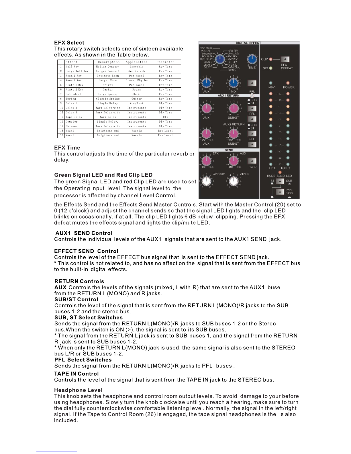
Clip LED
This ligh t normally indicates that t he channel signal level is ne aring the overlo ad point. The clip
indicat or circuit monitors the sig nal at many points i n the channel to ensure that it c atches all
instanc es of clipping. It illumina tes at +19 dBu and war ns that the gain or EQ boost shou ld be
reduced . When it lights, roughly 3 dB of h eadroom remain s.
Signal LE D
The signal LED lights when the channel level reaches approximatel y -20 dBu. This not o nly
indicat es which ch annels are activ e, but also serves as a mini leve l meter.
The PAN control kno bs set the positio n within the stere o field of each signal that is se nt to the
GROUP bus 1 -2 and STEREO bus L-R.
The BAL control k nobs set the balan ce between left and right cha nnels and assigns the signa ls
that are re ceived at INPUT L (CH9, 11,13, 15) to SUB bu ses 1 or Stereo bus L, a nd the signals
receive d at INPUT R (CH10, 12,14, 16) to SUB buse s 2 or Stereo bus R.
SUB, ST,PFL Select Switches
Used to send t he signa l o f each channel to the S UB bus, Stereo b us L-R , and PFL.When the
switch is ON (>), the si gnal is sen t to the rela tive bus. This swi tch lets yo u monitor the channel's
pre-fad er signal. To set the switch on, press it in ( ) so that it lights u p. When the switch i s on,
the mixer outputs the c hannel' s pre-f ader si gnal to the PHONES and C-R OUT jacks, for
monitor ing.

Phantom P ower Switch
This Swit ch applies +48 VDC voltage to the input XLR conne ctors to power microphone s
requiri ng phanto m power.
If phantom powe r is used, do not connect unbalanced d ynamic microphones o r ot her devices to
the XLR inp uts.
Contour S witch
Engagin g this switch enhances the si gnal by adding both bass and tr eble frequenci es. Thi s is
especia lly eff ective at lower vo lumes or for tape/CD playba ck.
Mic (XLR) I nputs
XLR balan ced input s are optimized fo r a microphone or other low imp edance source. P in 2 is
the posit ive input. Because of the wid e range of gain adju stment, signal levels up to + 14 dBu
can be acco mmodate d.
Rear Panel
Two eight- segment LED arrays are prov ided to monitor th e levels of the main left/rig ht outputs.
These met ers range from -30 dB to +19 dB. The 0 dB position on the meter corresponds to +4
dBu at the ou tputs.
Level-M eter Signal Swit ches (ST-GROUP Toggle S witch and 2TR IN Swi tch)
These lev el-meter switches, toge ther with the chan nel PFL switches, select th e signal that is
sent thro ugh the C-R/PHONES contro l to the C-R OUT jac ks, the PHONES jack, and the le vel
meter.Th e following illustratio n shows how the swit ch settings correspond to t he signal
selecti on.1 If t he in put c han nel's PFL switch is on ( ), then only the channel's PFL ou tpu t it se nt to t he C- R OUT
jacks, PHONES jacks, and lev el me ter. 2 If th e 2TR I N swi tch i s ON ( ), t he si gna l sup pli ed to t he 2T R IN ja ck is s ent t o
the C-R OUT jacks, PHONE jacks, and level meter. If the 2TR IN switch is OFF, then the Group or Stereo signal is
sent instead (as determine d by th e ST-G ROU P toggle switch).
This LED li ghts when the Phantom Power Switch (25) has bee n engaged.
Phantom P ower LED
This LED in dicates AC power is supplied t o the unit‚ the powe r switch is on, and the unit is
functio ning properly.
Power LED
LED Meter s
ST Master F ader
Adjusts t he signal level to the ST OUT jacks.
SUB 1-2 Fad er
Adjusts t he signal level to the SUB OUT 1 and SUB OUT 2 jacks.
2TR IN Cont rol
Adjusts t he level of the signal sent fro m the 2TR IN jack to the S tereo bus.
PHANTOM +48 V Switch
This swit ch toggles phantom power on a nd off. If you set t he switch on, the mixer suppl ies
power to al l channel s that provide XLR m ic input jacks (CHs 1-4, 5/6, 7/8 on VZ-12USB,CHs16,7/8,9/10 on VZ-16U SB). Set this switch on when us ing one or more condenser
microph ones.When this switch is on , the mixer suppli es DC +48 V pow er to pins 2 and 3 of all
XLR-typ e MIC INPUT jacks.
*Be sure to leave this switch OFF when you are not using phantom power. Hummin g or da mag e may
result if you connect to an unba lan ced d evi ce or t o an un gro und ed tr ans for mer w hil e thi s swi tch i s on. But n ote t hat t he
switch may be left on without pr obl em wh en co nne cti ng to b ala nce d dynamic microphones .
*To avo id da mage to speakers, be sure to turn off am pli fie rs (o r pow ere d spe ake rs) before turning this switch on or
off.

Tape In/ Out
The tape in put jacks are designed to acc ommodate tape‚ C D, or computer sound card out put
levels. The outp ut level is +4 dBu for c onnecting to a recorder or so und card input. The tape
inputs ca n be used as an additional ster eo input by engagi ng the Tape /USB to Main Mix swi tch
(27). The tape inp ut can also be used to m onitor the recorder/sou nd card output wit hout the risk
of feedba ck.
NOTE: The USB inpu t is routed to the Tape I nput left/righ t. If another device is conne cted to the
Tape Input, t his signal will be combined w ith the USB input si gnal.
MON Send
The MON Sen d features a 1⁄4” TRS Z-bal anced jack in the master sect ion. This outp ut can be
used with t he Tip, Ring, Sleeve (TRS) bal anced or Tip, Sleev e (TS) unba lanced connect ors.
The MON mix i s determined by th e amount of signal being sent t o the MON bus in each ch annel
and by the Mo nitor Master control (19) .
EFX Send
The EFX Send feature s a 1⁄4” TRS Z-balan ced jack in t he master s ection. These outputs c an be
used with Tip‚ Ring, Sleev e (TRS) balance d, or Tip, Sle eve ( TS) unbala nced connectors. The
EFX mix is determ ined by t he amoun t of sign al being sent to the EFX bus in each channel and
by the EFX ma ster control.
Control R oom Outputs
The Contr ol Room outputs feature two 1 ⁄4” TRS Z-bala nced jack s. These outpu ts can be use d
with Tip, Ri ng, Sleeve (TRS) balanced , or Tip, Sleeve (TS) u nbalanc ed connectors. The
Control R oom output level is adjuste d with the Headpho ne level co ntrol (21).
Left/Ri ght Outputs
The left/ right Outputs fe ature two 1⁄4” TRS Z-bala nced jacks and two fully bala nced XLR
outputs . The 1⁄4 ” outputs can be use d with Tip‚ Ring, Sleeve (TRS) b alanced or Tip, Sle eve
(TS) unba lanced connectors. Th e output level is set by the Mast er Level Faders (3 0). Both
outputs c an be used simultaneously.
Headpho ne Output
The Headp hone Output is a 1⁄4” TRS (Tip= Le ft; Ring = Right; Sl eeve = Ground). The signa l
sent to thi s output is normally the left/right mix. When t he Tape to Control Room switc h is
engaged , the tape input signal is adde d to the left/righ t mix and can be monitored in the
headpho nes.
Power Swi tch
Depress ing the pow er switch suppli es power to the unit .
REAR PANEL
Stereo (1 ⁄4”) Inputs
These 1⁄4” unbalanced inputs work as a stere o line input using both jacks o r as a mono input if
the connection i s made to the left/mono input only. The A/B in put sel ector must be in the “A”
RCA Inputs
These RCA inpu ts work as stereo line inp uts. The A/B in put selecto r must be in th e “B” position
for these j acks to be active.
Line (1⁄4 ”) Inputs
Line inputs provide 1⁄4” balanced (TRS) 10 k Ohm impedance input. The tip i s th e po sitive inpu t
and should be used for unba lanced inputs. It has 20 dB less gain t han the XLR in put and does
not have ph antom power available. The Mic and L ine inputs shoul d not be used simultaneousl y.
Insert
The 1⁄4” TRS conn ectors allow external si gnal proces sors to be inserted i nto the channel signal
path. Tip= Send; Ring=Return; Slee ve=Ground.

Specifications
For the mor e technical-minded, her e are some detailed
specifi cations for the VZ operating l evels.
Input Cha nnels
Mic In Sens itivity Range: -60dBu to 10 dBu nominal, +5d Bu maximu m
Line In Sen sitivity Range: -40dBu to - +10dBu nominal, +25dBu ma ximum
Mic/Lin e Gain Range: +10 to +60dB
Equaliz ation
High Shel ving: 12k Hz, +/- 15dB
Mid Bandp ass/Ban d Reject: 2.5 kHz, + /- 15dB
Low Shelv ing: 80Hz , +/- 15dB
Aux Send
Aux Send Ga in Range: -∞ to +10dB
Aux Retur ns
Aux Retur n: -∞ to +15dB
Effects Level Ga in Range: -∞ to +15d B
Channel L evels
Channel L evel Gain R ange: -∞ to +10dB
Master Le vels
Main Mix, C trl Room Gain
Range: -∞ t o +10dB
1/4” Inpu ts
Stereo Aux R eturn Lev el: +4dBu nomina l, +20dBu maximum
RCA Inputs
Tape In Level : -10dBV no minal, +5dBV max imum
1/4” Outp uts
Main Mix, C trl Room, Ext Aux Send Level: +4 dBu nominal, +20 dBu maxim um Headphone
Output: 7 5 ohm output imped ance >105 mW into 75 ohms, >40 mW into 600ohms
RCA Outputs
Tape Out Leve l: -10dBV nominal, +5dBV ma ximum
Power Adapter I nput
This unit p rovides 17 VAC at 1200 mA.
smoothl y. As with nea rly all power supp ly units, this one tends to get warm when left on for a
This is per fectly normal.
USB port
The USB por t is used to connect the VZ Series U SB mixer to a comput er for recording or
playing b ack digit al audio to/from y our computer. The USB port s ends the mixer's m ain/tape
stereo ou t to the computer. The USB por t receives digital audio fr om the computer; i t can then
be assign ed throug h the “Tape/USB to Mix ” switch (27) to the m ain left/right output. Co mpatible
®
with Wind ows XP, ME & 2000. Also compa tible with Mac OS X® 1 0.0 or later.
 Loading...