

SKP Pro Audio VX-03, VX-02 User Manual
ELECTRONIC CROSSOVER
User’s Manual
VX-02
VX-03
( English Version )
VX-02 ELECTRONIC CROSSOVER
INTRODUCTION
Congratulations on your purchase of the VX-02.
Crossover. We are confident you will find this crossover to be the finest product of its kind in this price range .We
have taken care to include all of the features you need to make your system sound its best. Some of the features
common to VX-02 crossovers are:
·Back panel switches for selecting the operating mode of the crossover.
·Back panel switches indicating the selected range of crossover frequencies. Both of these features have LED
indicators on the front panel so you can see at a glance which mode the unit is in.
·Low frequency summed output designed specifically for mono subwoofer applications.
·Phase invert switches on all outputs.
·Individual level controls on every output.
We are sure you will agree that these crossovers are built to provide extremely high quality frequency division for
all applications.
VX-02 FUNCTIONS and PERFORMANCE FEATURES x10 OPERATION
If you are using your system in stereo 2-way or 3-way mode, the needed crossover frequency may be higher than
960 Hz, making it necessary to set the x10 switch to the active position. This changes the range of operation of
the frequency selector from 45-960 Hz to 9.6 kHz. All other frequency selectors remain the same. When using the
x10 switch, ALWAYS ensure that the amplifiers feeding all speaker systems are turned off or that the input gain
controls on the power amplifiers are turned down before changing the setting of the x10 switch. Not doing so may
send a spurious signal to the outputs of the crossover when the x10 switch is engaged, and may damage speaker
systems which are powered any the time of the spurious signal.

POLARITY SWITHCH
Every output is equipped with a polarity (φ) reverse switch on the front panel. When speakers are not "in phase",
the frequency response of the system is compromised, particularly in the low frequencies. Out of phase signals
can also cause "comb-filtering" in the high frequencies. the polarity switch is extremely useful for fine tuning your
sound system for peak performance. An LED is activated when the output polarity is reversed.
LOW FREQUENCY SUMMING
The other feature accessed on the back panel is " low frequency summing". This is useful with systems that
utilize mono subwoofers.
Activating the LF sum switch "sums" the low frequencies of both the left and right inputs. The sum is sent to
channel one's low output marked "LF SUM" , while channel two's low output is not used, and channel two's pase
invert led is disabled, indicating it is not operational in "LF SUM" mode. The summed low frequencies represent
all the low frequencies of both the left and right inputs, and since lows are generally non-directional anyway, it will
not detract from the true stereo picture of the source material..
RACK MOUNTING, GROUNDING AND SAFETY
You should avoid mounting the unit near large power transformers or motors. Route the AC cord away from audio
lines and plug it into a power source close by , if the power cord must cross over audio lines, you should take care
to them cross at 90degree angles.
The input and output connector are balanced.
The VX-02 crossovers have differentially balanced input and output circuits. Balanced wiring is recommended,
even with unbalanced source devices, especially when running long paths. Twin-conductor, shielded cable is
more reliable since it does not depend on the shield wire itself to complete the signal connection. Using twin
conductor cable, a broken shield may only result in a slight increase in noise or hum due to the lack of shielding.
You may also use unbalanced cables to connect to and from the crossover.
TROUBLESHOOTING No SOUND
If there appears to be no power:
·Check that either the stereo or mono LED on the front panel of the VX-02 is lit
·Check that the power cord is seated properly in the back panel of the crossover and that it is plugged into an
active AC power source.
If there appears to be power, but no audible signal:
·Confirm that active audio lines are connected to the crossover's inputs and outputs.
·Check that both the input and output gain controls are advanced sufficiently.
·Check to make sure that you have turned up the amplifiers' outputs.
ABNORMAL AUDIO OUTPUT
·Ensure that the proper mode for your setup has been selected via the rear panel mode switches.
·Check the LF Sum switch.
·Check the x10 switch, this changes the range of the crossover frequency from 45-960Hz to 450 Hz-9.6 kHz.
WEAK AND /OR DISTORTED AUDIO
·Check that a clean signal is being fed to the crossover.
·Confirm that the input wiring is correct.
Check that the grounds of the audio signal path and the chassis and power line of all units in the system are
·
connected.
HUM AND/OR Buzz
If you suspect that the hum is caused by a ground loop:
·Systematically remove and /or connect the audio grounds of the devices in the signal path.
·Remember, for safety you must maintain connection to chassis ground. Never lift a safety ground.
·If you suspect the hum is not caused by a ground loop.
·Check the audio at an earlier stage in the audio chain.
·Low level equipment should be mounted away from power amplifiers to avoid induction of this type of hum.
·Be certain that all audio wiring except for loudspeaker lines is well shielded, and that low level wiring is not run
parallel to and /or in close proximity to AC power wiring.
INTERMITTENT AUDIO
·Check the other equipment and the wiring to make certain that the signal is not intermittent earlier in the chain.
·Check the integrity of all cables using a cable tester.
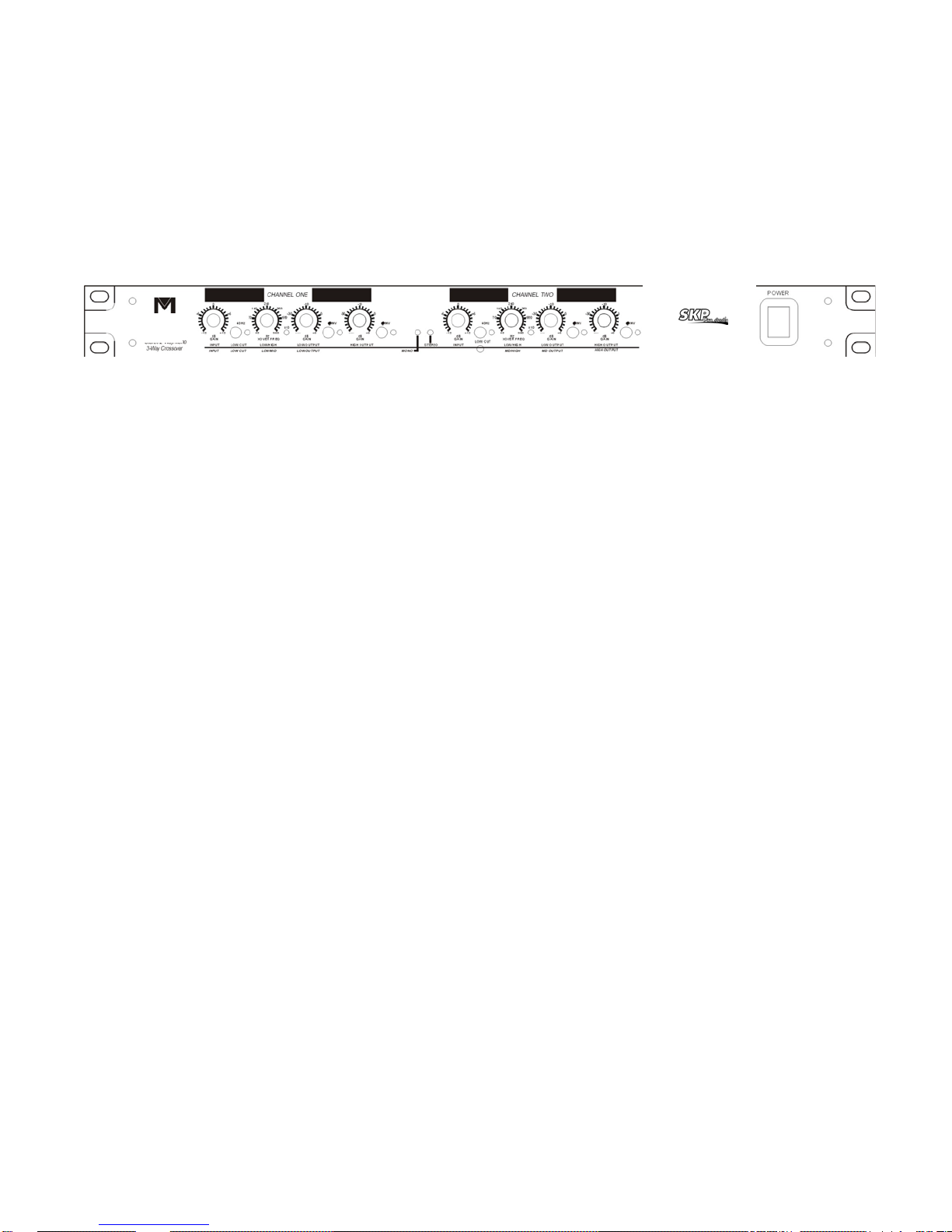
STEREO 2-WAY-MODE
In 2-way stereo mode the controls are marked BELOW the horizontal blue line.
Channel one and Channel Two functions are identical in the stereo mode. LEDs are disabled for controls which
are non-functional in this mode.
[1]&[5] INPUT GAIN Controls the INPUT level with +/- 12dB of gain.
[9]&[15] LOW CUT Switch for selecting the 40 Hz high pass filter. An LED indicates the selection.
[2]&[6] LOW/HIGH Selects crossover point between the LOW and HIGH output
[10]&[16] x10 LED Indicates that the LOW/HIGH crossover frequency range is 450 Hz to 9.6 kHz.
[3]&[7] LOW OUTPUT Controls the low Frequency output level with a range of -∞to +6dB.
[11]&[17] PHASE INVERT Switch for reversing the polarity on the low output. An led indicate the
selection.
[4]&[8] HIGH OUTPUT Controls the high frequency output with a range of -∞ to +6-dB.
[12]&[18] PHASE INVERT Switch for reversing the polarity on the high output. An led indicates the
selection.
[14] STEREO Led indicating stereo mode operation.
MONO 3-WAY MODE
In 3 -way mono operation the controls are marked ABOVE the horizontal blue line. Front panel controls not
described in this section are not active in mono 3-way mode. LEDs are disabled for controls which are
nonfunctional in this mode.
[1] INPUT GAIN Controls the input level with +/- 12dB of gain.
[9] Low CUT Switch for selecting the 40 Hz high pass filter. An led indicates the selection.
[2] LOW/MID Selects crossover point between low and mid frequencies.
[10] x10 LED Indicates that the Low/MID crossover range is 450 Hz to 9.6 kHz.
[6] Mid/High Selects the crossover point between MID and HIGH frequencies.
[16] x10 LED Indicates that the MID/HIGH crossover frequency range is 450 Hz to 9.6 kHz
[3] Low OUTPUT Controls the low frequency output level with a range of -∞to +6 dB.
[11] PHASE INVERT Switch for reversing the polarity on the Low Output. An LED indicates that the
phase is reversed.
[7] MID OUTPUT Controls the mid frequency output level with a range of - ∞to +6 dB
[17] PHASE INVERT Switch for reversing the polarity on the mid output. An led Indicates that the
phase is reversed.
[8] HIGH OUTPUT Controls the high frequency output level with a range of - ∞to +6dB
[18] PHASE INVERT Switch for reversing the polarity on the high output. An led indicates that the
phase is reversed
[13] MONO Led indicating mono mode operation.
On the back panel of the VX-02 there are markings to help you connect the source devices and amplifiers to your
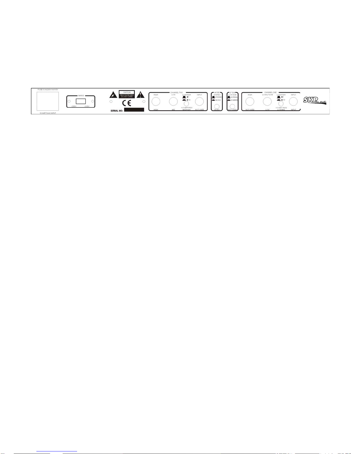
crossover. To operate the VX-02 in stereo 3-way operation, follow the top row of markings horizontally along the
length of the VX-02 for stereo 2-way operation of the VX-02 use the second row of mark ings directly above the
connectors. For mono 4-way operation of the VX-02 use the markings directly below the connectors. The
connectors not used in the selected mode are marked "not used". This designation applies only to that mode of
operation.
The VX-02 is marked in a similar way: for stereo 2-way operation use the markings ab ove the connectors. To
operate the VX-02 in mono 3-way mode use the markings below the connectors. The connectors which are not
used in the selected mode are marked "not used". This designation applies only to that mode of operation.
AUDIO CONNECTIONS
·Before connection anything to the crossover,, make sure it is not connected to any power source.
·Be sure that the source device(equalizer, compressor, nixing console, etc.) for the VX-02 is turned off. Connect
the output(s) of the source device to the inputs of the crossover, following the rear panel markings carefully.
·Make sure that the amplifiers which will be used to drive your speaker system are turned off. Using the back
panel markings as a guide, use high quality cables to connect the amplifiers to the appropriate outputs of the
VX-02 ELECTRICAL CONNECTIONS
Ensure that your VX-02 crossover conforms to the AC power specifications in your area, by checking the marked
voltage spec on the rear of the unit. Never plug the incorrect voltage into your
Input:
Connectors: 1/4"TRS
Type: Electronically balanced/unbalanced, rf filtered
Impedance: Balanced > 50kΩ,unbalanced>25kΩ
Max Input Level: +22dB typical, balanced or unbalanced
CMRR: >40dB, typicality >55dB at 1 kHz
Output
Connectors: 1/4"TRS
Type: Impedance-balanced/unbalanced, RF filtered
Impedance: balanced 220Ω,unbalanced100Ω
Max Input Level: >+21dBu Balanced / unbalanced into 2kΩ or greater
PERFORMANCE:
Bandwidth: 20 Hz to 20 kHz, +0/-0.5 dB
Frequency Response: < 3 Hz to >90kHz, +0/-3 dB
Signal-to-Noise: Ref: +4 dBu, 22 kHz measurement bandwidth
Stereo Mode: Mono Mode:
Low Output: > 94dB > 94dB
Mid Output: > 93 dB
High Output: > 91dB > 91dB
Dynamic Range: >106dB, unweighted, any output
THD+Noise: <0.004% at +4 dBu,1 kHz
<0.004% at +20 dBu,1 kHz
Interchannel Crosswalk: < -80dB, 20Hz to 20 kHz

CROSSOVER FREQUENCIES:
Stereo Mode:
Low/High: 45 to 960 Hz or 450 Hz to 9.6 kHz (x10 setting)
Mono Mode:
Low/Mid: 45 to 960 Hz or 450 Hz to 9.6 kHz (x10 setting)
Mid/High: 45 to 960 Hz or 450 Hz to 9.6 kHz (x10 setting)
Filter Type: Linkwitz-Riley,24 dB/octave, state-variable
FUNCTION SWITCHES:
Front Panel:
Low Cut: Activates 40 Hz Butterworth, 12 dB/octave high-pass filter, one switch per
channel.
Phase invert: Inverts the phase at the output, one switch per output.
Rear panel:
X10: Multiplies crossover frequency range by 10, one switch per channel.
Mode: Selects stereo/mono and 2/3/4-way operation.
LF sum: Selects normal(stereo) or mono-summed low frequency operation.
INDICATORS:
Stereo Operation: Green LED
Mono Operation: Yellow LED
Low Cut: Red LED per channel
X10: Green LED per channel
Phase Invert: Red LED per output (3 per channel)
POWER SUPPLY:
Operating Voltage: 100 VAC 50/60 Hz,
230 VAC 50/60 Hz
power Consumption: 15 watts
Mains Connection: IEC 320 receptacle

VX-03 ELECTRONIC CROSSOVER
INTRODUCTION
The VX-03 is a stereo 3-way, mono 4-way crossover. These high-quality crossover networks are designed to
extract maximum sound quality from your multi-amped sound system at a price working musicians can afford.
Accurate state-variable, 18 dB/octave butterworth filters prevent peaks or dips in the output at crossover points,
ensuring good driver protection by rolling off crossover frequencies rapidly.
A two-pole, high-pass filter may be electronically inserted at 40 Hz using a switch on the front panel, and a
variable low frequency summed output is available for mono subwoofer applications.
The rear panel of the VX-03 is clearly labeled for stereo and mono operation, and all outputs on the VX-03
except the mono low frequency sum output include phase switches.
INSTALLATION
Install the crossover in a rack. Route the AC power cord away from audio lines and plug into a convenient outlet
connect audio lines to the crossover using the appropriate input jacks to channels 1 and 2 (for stereo operation),
or to channel 1 only (for mono operation). Connect the appropriate output jacks for stereo 3-way, mono 4-way
operation. The rear panel is clearly marked for proper connection. Follow the top labels for stereo connection or
the bottom labels for mono connection.
All inputs and outputs are balanced.
The VX-03 may be connected balanced or unbalanced. Input impedance is 40K ohms, and output impedance is
102 ohms.
Once the crossover is installed, adjusted, and tested, an optional security panel may be secured to the front panel
of the unit to prevent tampering.
SETUP
Consult your speaker and driver manufacturer's specifications for the recommended crossover frequencies.
Basic setup procedures for the crossovers are follows:
Label each power amplifier for its respective frequency band.
VX-03: LOW, MID, or HIGH for stereo operation; LOW,LOW-MID,HIGH-MID or HIGH for mono operation
Set each power amplifier volume control at maximum and connect each power amplifier output to its correct
speaker or driver.
Apply power to the crossover. DO NOT TURN ON THE POWER AMPLIFIERS YET.
STEREO OPERATION
Using the markings in the top row of the front and rear panels, set each channel as follows:
Set the gain control to 0dB. Set all level controls to -∞ and switch in the 40Hz highpass filter desired.
VX-03: Set the LOW/MID crossover frequency for each channel according to the front panels markings.
VX-03: If the desired frequency is above 500Hz, the range switch must be engaged (LED indicator lit). If the
desired frequency is below 500Hz, the range switch must be disengaged (LED indicator off).
When the range switch is engaged, the frequencies marked around the LOW/MID frequency control are
multiplied by ten. In other words, if the LOW/MID frequency is set at 250 and the range switch is engaged, the
actual crossover frequency is 2.5Khz.
VX-03: Set the MID/HIGH crossover frequency. The channel A MID/HIGH frequency control has two sets of
markings. When using the crossover in stereo mode, use the lower frequency markings to set the MID/HIGH
crossover point. This frequency control has no range switch, and in stereo mode extends to 7.5kHz.
Send a broadband signal into the crossover and slowly bring up the LOW level control. Set the control for the
desired level. The gain control can be used to SKP the if needed.
VX-03: Apply power to the MID frequency amplifier and turn up the MID level control to the desired level.
VX-03: Finally, apply power to the HIGH frequency power amplifier and bring up the HIGH level control to the
desired level.
Once the output levels are set, any phase problems can be corrected with the phase inversion switches on the
real panel. THE PHASE INVERSION SWITCHES ON THE VX-03 ARE MECHANICAL SWITCHS AND SHOULD
ONLY BE CHANGED. WHEN THE POWER AMPLIFIER FOR THAT OUTPUT IS OFF. Turning down the level
controls on the VX-03 will not prevent transients from appearing at the outputs when changing the phase

switches while the crossover is on. These transients can damage power amplifier, speakers, and drivers.
STEREO OPERATION USING A MONO SUBWOOFER
This mode of operation provides:
VX-03: Channel A and channel B HIGH frequency outputs, channel A and channel B MID frequency outputs, and
one summed LOW frequency output.
The setup procedure is the same as for stereo mode, except that, instead of connecting both low frequency
outputs, connect only the low frequency sum output to the LOW frequency amplifier. Set both LOW level controls
to the same level to ensure that both controls the same amount of signal to the LOW frequency sum output.
Note that there is no phase inversion switch on the VX-03 for the LOW frequency sum output. Any phase
problems must be corrected using the phase inversion switches on the other four outputs.
MONO OPERATION
Depress the stereo/mono switch(LED indicator lit). When operating the crossover in stereo mode. The MID/HIGH
frequency control of the VX-03 is variable from. 75kHz-7.5kHz. When operating the crossover in mono mode, the
HIGH-MID/HIGH frequency control range is from 2kHz-20kHz.
The mono mode setup procedure is the same as for stereo mode, except that the bottom row of marking on the
front and rear panels will be followed instead of the top row. Be sure that the amplifiers are off, that the gain
control is set to 0dB, and that the level control is set to -∞ before proceeding to adjust the crossover frequencies
and levels. The LOW frequency sum output is not usable in the mono mode.
VX-03 SPECIFICATIONS
Crossover type: Stereo 3-way , mono 4-way.
1/0 connectors: VX-03: Balanced/unbalanced connections.
THD+NOISE: Less than 0.006%.
Sign-To-Noise Ratio: Greater than -90dB
Filter Type: 18 dB/octave butterworth state-variable filters.
Crossover Frequencies -stereo: LOW/MID :50Hz to 5kHz in two ranges,MID/HIGH:750Hz to 7.5kHz.
Mono: LOW/LOW-MID: 50Hz to 5kHz in two ranges, LOW-MID/HIGH-MID:750Hz to 7.5kHz, HIGH-MID/HIGH:
2kHz to 20kHz.
Input impedance: 20k ohms unbalanced, 40k ohms balanced.
Maximum input level: +21dB (ref:0.775Vrms).
Output impedance: 102 ohms.
Maximum output level: +21dB (ref: 0.775Vrms).

DIVISOR DE FRECUENCIA ELECTRONICO
VX-02
VX-03
Manual del Usuario.
( English Version )
 Loading...