

SKP Pro Audio MAX G-1210X,MAX G-1810X,MAX G-3610X,MAX G-5010D User Manual

1
MAX G - X SERIES
PROFESSIONAL POWER AMPLIFIER
AMPLIFICADOR PROFESIONAL
AMPLIFICADOR PROFISSIONAL

2
MAX G-1210X/1810X/3610X/5010D
User’s Manual
Manual del Usuario.
Manual do Usuário.
SAFETY INFORMATION
CAUTION: To reduce the risk of electric shock, do not remove any cover(or the rear section). No user serviceable
parts inside. Refer servicing to qualified service personnel only.
WARNING: To reduce of fire or electric shock, do not expose this appliance to rain and moisture. Electrical
equipments should NEVER be kept or stored in damp environments.
This symbol, wherever appears, is intended to alert the user to the presence of un-insulated
dangerous voltage within the appliance ’s enclosure that may be of sufficient magnitude to a risk of
electric shock.
This symbol, wherever app ears, is intended to alert t he user to the presence of important operating
and maintenance (servicing) instruction in the literature accompanying this appliance.
3
This symbol means: indoor use on ly.
This symbol means: Read instructions.
SAFETY INSTRUCTIONS
1. Read Instructions All the safety and operating instructions should be read before this products is
connected and used.
2. Retain Instructions The safety and operating instr uct ions sho uld be kept for future reference.
3. Heed Waning All warnings on this appliance and in these oper ating instructions should be followed.
4. Follow Instruction All operating and other instruct ions should be followed.
5. Heat, Water and Moisture Do not place this appliance to c lose to any high heat sources such as rad iators.
Also this appliance shou ld be kept aw ay fro m direct cont act with liqu ids.
6. Ventilation The appliance should be situated so that it’s location or position does not interfere with it’s proper
ventilation. For example, t he appliance should not be situat ed on a sofa, bed, or similar surface that may block the
vent ilat ion o pen ing; o r ke ep the appliance away of those objects such as newspaper s, carpet which may cover the
ventilation op ening o r impede the flow of a ir through the venti la tion opening.
7. Power Source & Power Cord This appliance should be connected to a power supply only of the type
described in these operating instructions, or marked on the unit.
Power supply cord should be routed so that the are not likely to be walked upon or pinched by the items placed on
or against them. When removing the cord from a power outlet be sure to remove it by holding the plug attachment
and not by pulling on the cord.
Check the total maximum power of your AC wall outlet and make sure it has the enough power to mat ch t he Power
Consumption of this appliance, otherwise you could overload the wa ll outlet, which could cause fire.
8. Internal / External Voltage Selectors Int ernal o f exter nal volt age se lector switche s, if an y, sho uld only be
reset and re-equipped with a proper plug for alternative voltage by a qualified service technician . Do not attempt to
alter this yourself.
9. Object & Liquid Entry Take care to avoid any objects falling into or liquids ar e no t spilled in to the inside of
the appliance.
10. Cleaning Unplug the applian ce firs t and clean only with a dry clot h.
11. Non-use Period The power cor d of the app lianc e sho uld be unp lugg ed fro m the o utlet when le ft unuse d for
long periods of time.
12. Unpacking & Setup Please check your appliance for any damage after unpacking(before connecting) and
contact your dealer in ca se of any re lated complains. Take care of choosing your inst allation place and t he correct
4
AC connection. If built in to a case, be aware that the depth and the weight of some kind appliance(such as
Amplifier) does require an additional fixing on the backside o r the use of rack shelf supports. Never mount the
amplifier in a rack just by fixing it on the front p late – Manufacturer takes no responsibility in this case.
13. Damage Requiring Service Servicing is required when the appliance has been damaged in any way, such as
power cord or plug is damaged, liquid has been spilled or objects have fallen in the appliance, the app liance has
been exposed to rain or moisture, does not operate normally, or has been dropped. Refer all servicing to qualified
service personnel or contact your dealer. Do not attempt to repair by yourself.
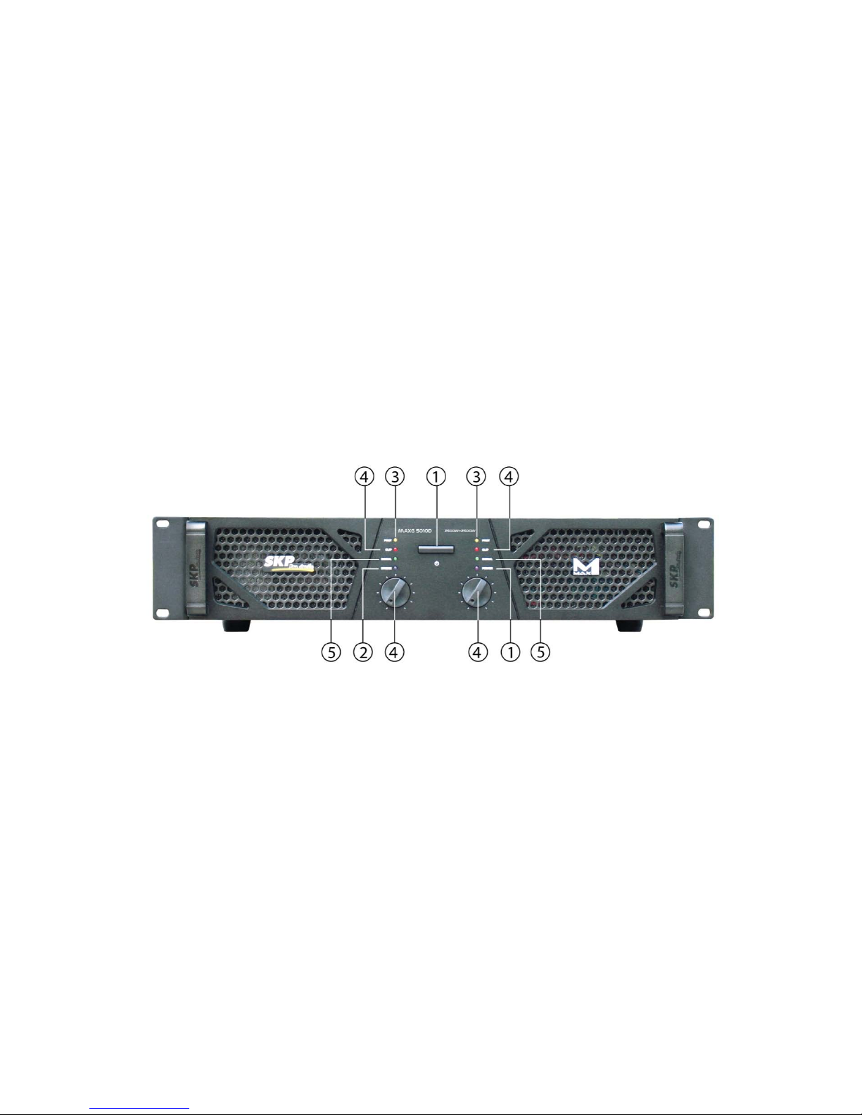
FRONT PANEL:
1、Power switch
When this switch is pushed down, the power on , the amplifie r is re ady to work.
2、Bridge mode indicating LED (Blue)
This LED will be on when working under Bridge mode.
3、CHA/CHB protection indicating LEDs (Yellow)
The LEDs will be on in the follow ing three co nditions:
A. 3-5 seconds after turning on power, or after turning off power, the amplifier is under unstable status.
Indicating the power amplifier is still disco nnect ed from speakers.
B. When the amplifier parts' temperat ur e is over 93℃.
C. Whe n s omet hing is wrong with t he ampli fier.
4、CHA/CHB peak level indicating LEDs (Red)

5
The LEDs will be on in the two situations:
A. When the output signal has reached its clipping level, the LE D light s ; poss i bly resultin g in dis tortion. Shou ld
this occur, adjust the input level control so that the Peak LED tur ns off.
B. As the signal has been input, the Peak LED lights continuously, but the speaker has no voice, it is
possibly that it is short circuited for loading. Youshould turn off the amplifie r. Find o ut wher e the t rouble is and
renew operation.
5、CHA/CHB signal indicating LEDs (green)
This LED will be on when the amplifie r is wo rking normall y.
6
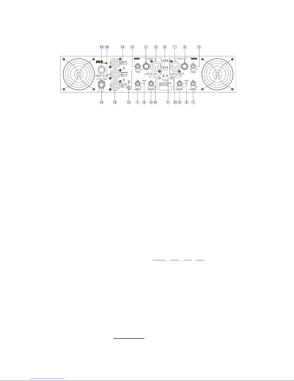
REAR PANEL 1: (MAXG 1210X/MAXG1810X/MAXG 3610X)
1 , 2. CHA Input (Balanced) Standard XLR socket, used for all long cable runs. Please note : Pin
1= Ground , Pin 2 = Positive (+) , Pin3 = Negative (-).
3 , 4. 1/4” Input Socket Connec t mixer outputs fo r CHA and CHB
5. Low Cut Filter Re moves ultra-low frequency from the a udio s ignal an d
ensures that most power can go to the middle frequencies so there is less chance for audio
clipping or make your speaker woofer damaged.
Remove range: 0 ~ 170Hz
6. Stereo / Bridge Mode Switch Set to choo se the out p ut mode o f amplifier.
Br idge mono oper ation is easil y achi eved and give s you t he outp ut pow er of bot h channe ls wit h
just one mono output. Follow these instruction for successful Bridge operation :
A> Set the Mode Switch to Bridge posit ion while amplifier is off
B> Connect input signal
C> Connect your speaker to Bridge speakon so cket (Red col or ) only
D> The mini mu m load i mpe da nc e in Br idg e mod e is 8 ohm
E> To adjust level, use Channel A cont r ol and leave Channel B level at zero
7. Low / Mid Crossover Adjust the Low/Mid frequency of output
Range : 50 ~ 500Hz or 500 ~ 5kHz (Range switch pressed)
8. Mid / High Crossover Adjust the high frequency of o utput
Range : 750 ~ 7.5kHz
9. Range Switch Pressed to get the adjustable frequency range of Low/Mid crossover from 500
~5kHz
10. Output Frequency Selector 4 modes of Bypass / High / Mid / Low availab le, see detail
instruction below.
A> Bypass: No limit for the output frequency. but the low frequency output still controlled by
Low Cut Filter.
B> High: Amplifier working at High frequency output mode, both
Low/Mid and Mid/High work as the High-pass filter, Adjustable Ra nge : 750 ~
20kHz
C> Mid: Amplifier working at Middle frequency output mode.
Low/Mid filter works as the High-pass filter
Mid/High filter works as the Low-pass Filt er
Adjustable Range : 50 ~ 7.5kHz or 500 ~ 7.5kHz (Range switch pressed)
D> Low : Amplifier working at Low frequency output mode, both
Low/Mid and Mid/High filter work as the Low-pass filter
Output frequency Range : 0 ~ 500Hz
Note : The setting of Low Cut Filter is always valid for all kinds of above output
frequency selection.
7
11. Limiter On/Off Switch Use to choose auto-lim iter fu nc tion
12. Grounding Post
13,14. CHA/CHB Output Standard Speakon Socket for Stereo output, please note the Pin
designation as: 1+ , 2+ (connected) = Positive 1- , 2- (connected) = N egative
15. Bridge Output Standard S peakon Socket with Red color, for Bridge output use o nly, p lease
note the Pin desig natio n a s :
1+ , 2+ (connected) = Positive 1- , 2- (connected) = Negative
16. Recoverable Fuse When replacing the fuse, please make sure that you always use fuses o f the
same type, follow the Fuse instructions marked under the Recoverable Fuse housing.
17. Mains Power Cord Be fore connecting the amp lifier to a power outlet, please make sure that
the selected voltage (set by the Voltage se lect Switch) matches your local voltage and t he fuse
matches the specification marked u nder the Recoverable Fuse housing.
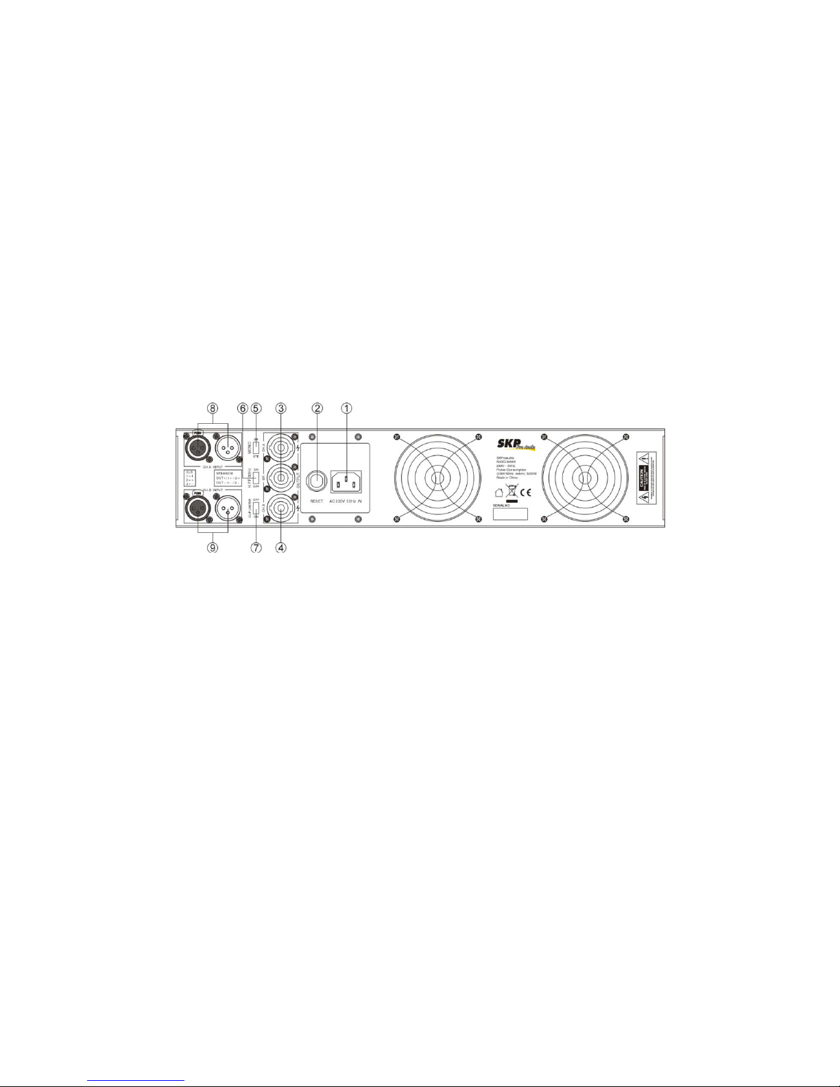
REAR PANEL 2: (MAXG 5010D)
1、 Power supply
AC230V 50Hz or AC 115V 60Hz
2、 Resettable fuse
When the amplifier malfunctions, t he fuse will automatically disconnect the circuit loop; after the
trouble is removed, t he fuse will automatically reset, and resume working.
3、 CHA /CHB Speakon output connector
Used by a standard Speakon connector. 1+ 2+, 1- 2-
4、 B RIDGED Speakon output connector
Used by a standard Speakon connecto r. 1+ 2+, 1- 2-
5、 Mode selector
For Stereo or Bridge mode selection.
6、 High Pass filter
While the switch positioned to “On”position, then the input signal under 30Hz will be cut off.
Bypass mode when the switch positioned on OFF posit ion
7、 Auto-Limiter switch
When then switch positioned to“ON”, the Auto-Limiter ins id e is ac tive。
8、 CHA XLR input connector
A standard XLR socket.
Pin1: ground Pin2: positive Pin3: negative。
9、 CHB XLR input connector
A standard XLR socket.
Pin1: ground Pin2: positive Pin3: negative。
 Loading...