

SKP Pro Audio MAX G-1200X,MAX G-1800X,MAX G-3600X,MAX G-5000D User Manual
1
MAX G - X SERIES
PROFESSIONAL POWER AMPLIFIER
AMPLIFICADOR PROFESIONAL
AMPLIFICADOR PROFISSIONAL
MAX G-1200X/1800X/3600X/5000D
User’s Manual
Manual del Usuario.
Manual do Usuário.

2
SAFETY INFORMATION
CAUTION: To reduce the risk of electric shock, do not remove any cover(or the rear section). No user serviceable
parts inside. Refer servicing to qualified service personnel only.
WA R NI N G : To reduce of fire or electric shock, do not expose this appliance to rain and moisture. Electrical
equipments should NEVER be kept or stored in damp environments.
This symbol, wherever appears, is intended to alert the user to the presence of un-insulated
dangerous voltage within the appliance’s enclosure that may be of sufficient magnitude to a risk of
electric shock.
This symbol, wherever appears, is intended to alert the user to the presence of important operating
and maintenance (servicing) instruction in the literature accompanying this appliance.
This symbol means: indoor use only.
This symbol means: Read instructions.

3
SAFETY INSTRUCTIONS
1. Read Instructions Æ All the safety and operating instructions should be read before this products is
connected and used.
2. Retain Instructions Æ The safety and operating instructions should be kept for future reference.
3. Heed Waning Æ All warnings on this appliance and in these operating instructions should be followed.
4. Follow Instruction Æ All operating and other instructions should be followed.
5. Heat, Water and Moisture Æ Do not place this appliance to close to any high heat sources such as radiators.
Also this appliance should be kept away from direct contact with liquids.
6. Ventilation Æ The appliance should be situated so that it’s location or position does not interfere with it’s proper
ventilation. For example, the appliance should not be situated on a sofa, bed, or similar surface that may block the
ventilation opening; or keep the appliance away of those objects such as newspapers, carpet which may cover the
ventilation opening or impede the flow of air through the ventilation opening.
7. Power Source & Power Cord Æ This appliance should be connected to a power supply only of the type
described in these operating instructions, or marked on the unit.
Power supply cord should be routed so that the are not likely to be walked upon or pinched by the items placed on
or against them. When removing the cord from a power outlet be sure to remove it by holding the plug attachment
and not by pulling on the cord.
Check the total maximum power of your AC wall outlet and make sure it has the enough power to match the Power
Consumption of this appliance, otherwise you could overload the wall outlet, which could cause fire.
8. Internal / External Voltage Selectors Æ Internal of external voltage selector switches, if any, should only be
reset and re-equipped with a proper plug for alternative voltage by a qualified service technician . Do not attempt to
alter this yourself.
9. Object & Liquid Entry Æ Take care to avoid any objects falling into or liquids are not spilled in to the inside of
the appliance.
10. Cleaning Æ Unplug the appliance first and clean only with a dry cloth.
11. Non-use Period Æ The power cord of the appliance should be unplugged from the outlet when left unused for
long periods of time.
12. Unpacking & Setup Æ Please check your appliance for any damage after unpacking(before connecting) and
contact your dealer in case of any related complains. Take care of choosing your installation place and the correct
AC connection. If built in to a case, be aware that the depth and the weight of some kind appliance(such as
Amplifier) does require an additional fixing on the backside or the use of rack shelf supports. Never mount the
amplifier in a rack just by fixing it on the front plate – Manufacturer takes no responsibility in this case.
13. Damage Requiring Service Æ Servicing is required when the appliance has been damaged in any way, such as
power cord or plug is damaged, liquid has been spilled or objects have fallen in the appliance, the appliance has
been exposed to rain or moisture, does not operate normally, or has been dropped. Refer all servicing to qualified
service personnel or contact your dealer. Do not attempt to repair by yourself.
4
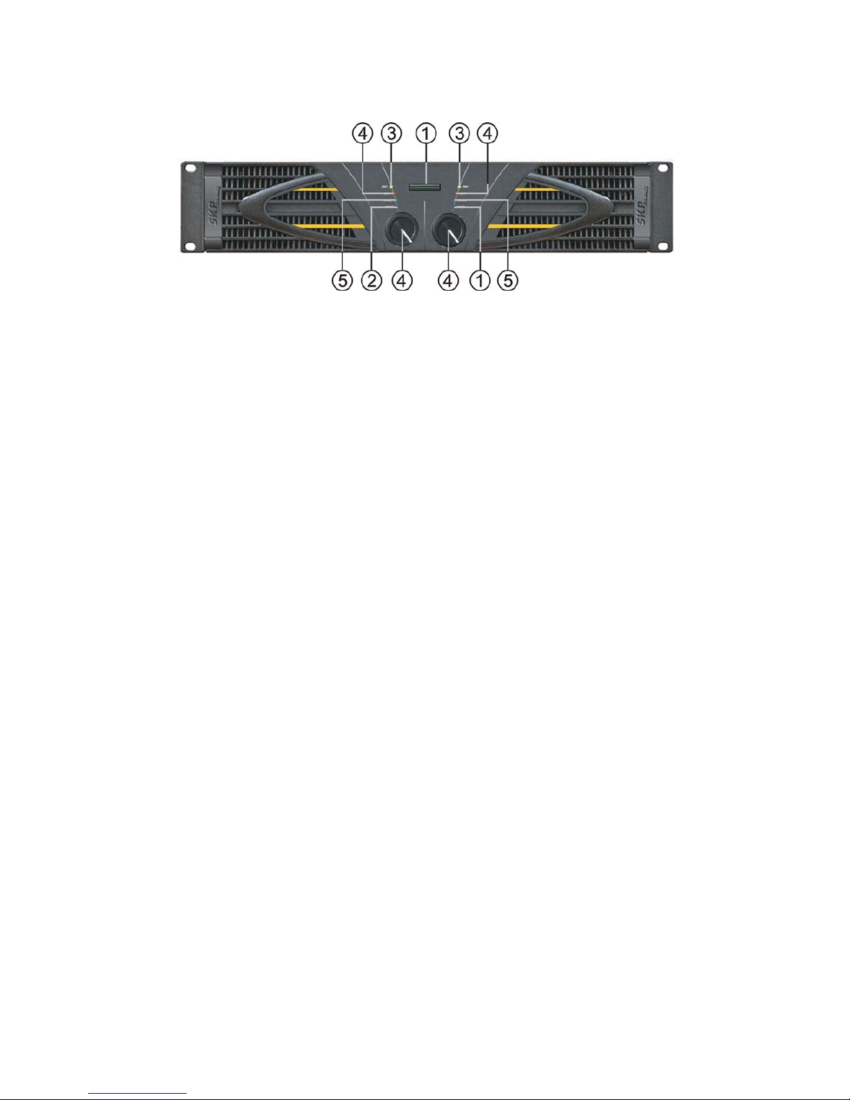
FRONT PANEL:
1、Power switch
When this switch is pushed down, the power on , the amplifier is ready to work.
2、Bridge mode indicating LED (Blue)
This LED will be on when working under Bridge mode.
3、CHA/CHB protection indicating LEDs (Yellow)
The LEDs will be on in the following three conditions:
A. 3-5 seconds after turning on power, or after turning off power, the amplifier is under unstable status.
Indicating the power amplifier is still disconnected from speakers.
B. When the amplifier parts' temperature is over 93.
C. When something is wrong with the amplifier.
4、CHA/CHB peak level indicating LEDs (Red)
The LEDs will be on in the two situations:
A. When the output signal has reached its clipping level, the LED lights; possibly resulting in distortion. Should
this occur, adjust the input level control so that the Peak LED turns off.
B. As the signal has been input, the Peak LED lights continuously, but the speaker has no voice, it is
possibly that it is short circuited for loading. Youshould turn off the amplifier. Find out where the trouble is and
renew operation.
5、CHA/CHB signal indicating LEDs (green)
This LED will be on when the amplifier is working normally.
5
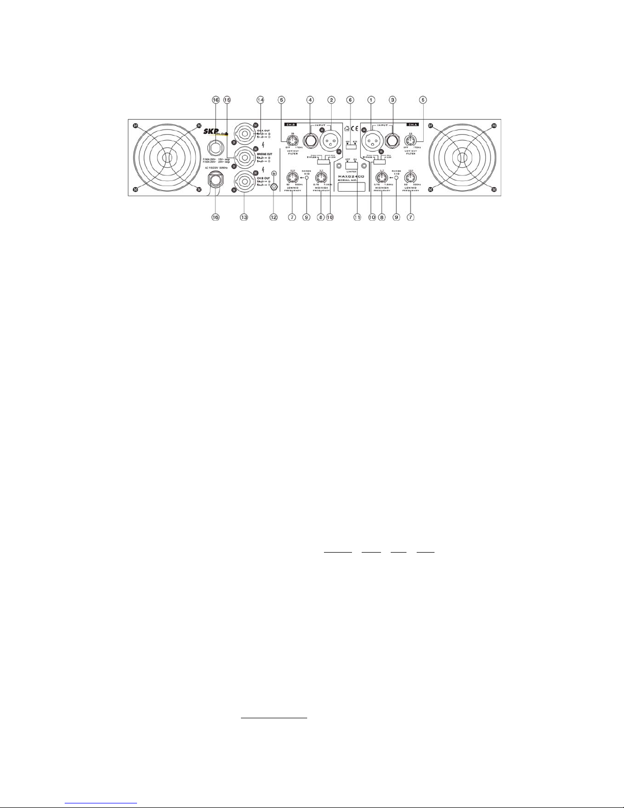
REAR PANEL 1: (MAXG 1200X/MAXG1800X/MAXG 3600X)
1 , 2. CHA Input (Balanced) Æ Standard XLR socket, used for all long cable runs. Please note : Pin
1= Ground , Pin 2 = Positive (+) , Pin3 = Negative (-).
3 , 4. 1/4” Input Socket Æ Connect mixer outputs for CHA and CHB
5. Low Cut Filter Æ Removes ultra-low frequency from the audio signal and
ensures that most power can go to the middle frequencies so there is less chance for audio
clipping or make your speaker woofer damaged.
Remove range: 0 ~ 170Hz
6. Stereo / Bridge Mode Switch Æ Set to choose the output mode of amplifier.
Bridge mono operation is easily achieved and gives you the output power of both channels with
just one mono output. Follow these instruction for successful Bridge operation :
A> Set the Mode Switch to Bridge position while amplifier is off
B> Connect input signal
C> Connect your speaker to Bridge speakon socket (Red color) only
D> The minimum load impedance in Bridge mode is 8 ohm
E> To adjust level, use Channel A control and leave Channel B level at zero
7. Low / Mid Crossover Æ Adjust the Low/Mid frequency of output
Range : 50 ~ 500Hz or 500 ~ 5kHz (Range switch pressed)
8. Mid / High Crossover Æ Adjust the high frequency of output
Range : 750 ~ 7.5kHz
9. Range Switch Æ Pressed to get the adjustable frequency range of Low/Mid crossover from 500
~5kHz
10. Output Frequency Selector Æ 4 modes of Bypass
/ High / Mid / Low available, see detail
instruction below.
A> Bypass: No limit for the output frequency. but the low frequency output still controlled by
Low Cut Filter.
B> High: Amplifier working at High frequency output mode, both
Low/Mid and Mid/High work as the High-pass filter, Adjustable Range : 750 ~
20kHz
C> Mid: Amplifier working at Middle frequency output mode.
Low/Mid filter works as the High-pass filter
Mid/High filter works as the Low-pass Filter
Adjustable Range : 50 ~ 7.5kHz or 500 ~ 7.5kHz (Range switch pressed)
D> Low : Amplifier working at Low frequency output mode, both
Low/Mid and Mid/High filter work as the Low-pass filter
Output frequency Range : 0 ~ 500Hz
Note : The setting of Low Cut Filter
is always valid for all kinds of above output
frequency selection.
6
11. Limiter On/Off Switch Æ Use to choose auto-limiter function
12. Grounding Post
13,14. CHA/CHB Output Æ Standard Speakon Socket for Stereo output, please note the Pin
designation as: 1+ , 2+ (connected) = Positive 1- , 2- (connected) = Negative
15. Bridge Output Æ Standard Speakon Socket with Red color, for Bridge output use only, please
note the Pin designation as:
1+ , 2+ (connected) = Positive 1- , 2- (connected) = Negative
16. Recoverable Fuse Æ When replacing the fuse, please make sure that you always use fuses of the
same type, follow the Fuse instructions marked under the Recoverable Fuse housing.
17. Mains Power Cord Æ Before connecting the amplifier to a power outlet, please make sure that
the selected voltage (set by the Voltage select Switch) matches your local voltage and the fuse
matches the specification marked under the Recoverable Fuse housing.
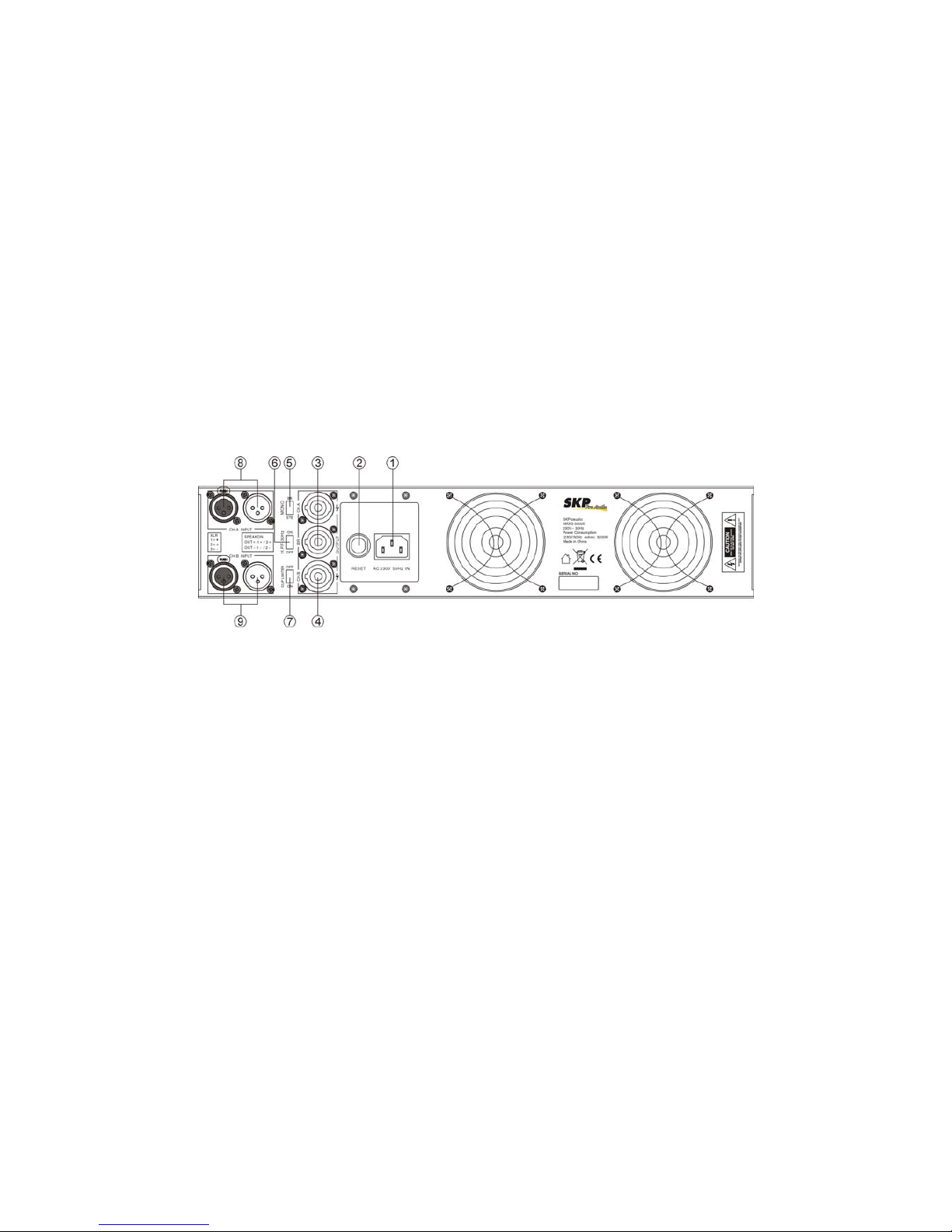
REAR PANEL 2: (MAXG 5000D)
1、 Power supply
AC230V 50Hz or AC 115V 60Hz
2、 Resettable fuse
When the amplifier malfunctions, the fuse will automatically disconnect the circuit loop; after the
trouble is removed, the fuse will automatically reset, and resume working.
3、 CHA /CHB Speakon output connector
Used by a standard Speakon connector. 1+ 2+, 1- 2-
4、 BRIDGED Speakon output connector
Used by a standard Speakon connector. 1+ 2+, 1- 2-
5、 Mode selector
For Stereo or Bridge mode selection.
6、 High Pass filter
While the switch positioned to “On”position, then the input signal under 30Hz will be cut off.
Bypass mode when the switch positioned on OFF position
7、 Auto-Limiter switch
When then switch positioned to“ON”, the Auto-Limiter inside is active。
8、 CHA XLR input connector
A standard XLR socket.
Pin1: ground Pin2: positive Pin3: negative。
9、 CHB XLR input connector
A standard XLR socket.
Pin1: ground Pin2: positive Pin3: negative。
 Loading...