

Page 1
VF Series
User Manual
MAN10521 Rev. 3.3 Jun. 2016
VF1000
SKOPE Vertical Freezer
Page 2

SKOPE Warranty Protection
Register now for peace of mind
It’s quick and simple. Take a few minutes to register
your SKOPE product and enjoy more efficient
support plus other warranty benefits. When
registering, make sure you have your cabinet serial
number at hand.
To register online:
Visit our website at www.skope.com/warrantyprotection
then complete and submit the online registration form.
Or freephone:
1800 121 535 (Australia)
0800 947 5673 (New Zealand)
SKOPE 1-year Extended Warranty
Extend your Warranty Protection by 1 year during registration. Please
check you have not already organised an extended warranty through
your dealer at time of purchase. For pricing information on an extended
warranty visit www.skope.com/warrantyprotection
Service & Support
We know you will get years of satisfaction from your new SKOPE
product when you follow a few simple preventative maintenance
guidelines.
Helpful information is available on our website
www.skope.com/serviceandsupport
Thank you for purchasing a SKOPE refrigeration product.
Page 3

SKOPE VF Series
User Manual
iii
CONTENTS
1 Installation
Safety First . . . . . . . . . . . . . . . . . . . . . . . . . . . . . . . . . . . . . . . . . . .4
Positioning the Cabinet . . . . . . . . . . . . . . . . . . . . . . . . . . . . . . . . . . . . 5
Climate Class . . . . . . . . . . . . . . . . . . . . . . . . . . . . . . . . . . . . . . . . .5
Freezer Location . . . . . . . . . . . . . . . . . . . . . . . . . . . . . . . . . . . . . . . 5
Power Cord . . . . . . . . . . . . . . . . . . . . . . . . . . . . . . . . . . . . . . . . . . 5
Ventilation . . . . . . . . . . . . . . . . . . . . . . . . . . . . . . . . . . . . . . . . . . . 5
Shelves . . . . . . . . . . . . . . . . . . . . . . . . . . . . . . . . . . . . . . . . . . . . . . . . 6
Optional Door Lock . . . . . . . . . . . . . . . . . . . . . . . . . . . . . . . . . . . . . . .6
2 Operation
Automatic Start-Up . . . . . . . . . . . . . . . . . . . . . . . . . . . . . . . . . . . . . . . 7
Loading Product . . . . . . . . . . . . . . . . . . . . . . . . . . . . . . . . . . . . . . . . .7
Electronic Controller . . . . . . . . . . . . . . . . . . . . . . . . . . . . . . . . . . . . . . 8
Introduction . . . . . . . . . . . . . . . . . . . . . . . . . . . . . . . . . . . . . . . . . . 8
Faceplate . . . . . . . . . . . . . . . . . . . . . . . . . . . . . . . . . . . . . . . . . . . . 8
Defrost . . . . . . . . . . . . . . . . . . . . . . . . . . . . . . . . . . . . . . . . . . . . . . 9
Continuous Cycle . . . . . . . . . . . . . . . . . . . . . . . . . . . . . . . . . . . . . . 9
Temperature Setpoint . . . . . . . . . . . . . . . . . . . . . . . . . . . . . . . . . . 9
Controller Reset . . . . . . . . . . . . . . . . . . . . . . . . . . . . . . . . . . . . . . 10
Alarms . . . . . . . . . . . . . . . . . . . . . . . . . . . . . . . . . . . . . . . . . . . . .11
3 Servicing
Cleaning . . . . . . . . . . . . . . . . . . . . . . . . . . . . . . . . . . . . . . . . . . . . . . 12
Cabinet . . . . . . . . . . . . . . . . . . . . . . . . . . . . . . . . . . . . . . . . . . . . . 12
Condenser Coil . . . . . . . . . . . . . . . . . . . . . . . . . . . . . . . . . . . . . . 12
Lighting . . . . . . . . . . . . . . . . . . . . . . . . . . . . . . . . . . . . . . . . . . . . . . . 13
Interior Light . . . . . . . . . . . . . . . . . . . . . . . . . . . . . . . . . . . . . . . . . 13
Sign Light . . . . . . . . . . . . . . . . . . . . . . . . . . . . . . . . . . . . . . . . . . . 14
Troubleshooting. . . . . . . . . . . . . . . . . . . . . . . . . . . . . . . . . . . . . . . . . 15
Page 4
4
Installation
User Manual
SKOPE VF Series
1 Installation
Safety First Always observe safety precautions when using any electrical appliance.
Read these instructions carefully and retain them for future reference.
When the appliance is used by or near young children or infirm persons,
close supervision is necessary, especially to ensure children do not play
with it.
Do not use this appliance for other than its intended use.
Do not cover the grilles or block the entry or exhaust of airflow by
placing objects up against the refrigeration unit.
Do not probe any opening.
Do not store explosive substances such as aerosol cans with a
flammable propellant in this appliance.
Only use this appliance with the voltage specified on the cabinet rating
label affixed to the inside of the cabinet.
Ensure the appliance has adequate ventilation as this is essential to
economical, high performance.
Be careful not to touch moving parts and hot surfaces.
For your own safety and that of others, ensure that all electrical work is
done by authorised personnel.
If the power supply flexible cord becomes damaged, it must be replaced
by an authorised service agent or similarly qualified person in order to
avoid a hazard.
Ensure all necessary safety precautions are observed during installation
or removal of the refrigeration unit.
This appliance is not designed to be stable while in motion. Use
extreme caution when moving or transporting the appliance.
Please contact SKOPE customer services for advice regarding disposal
of this appliance.
WARNING
Always isolate the freezer from the mains power supply before
attempting any maintenance.
WARNING
Twin unit freezers have two seperate power supplies. Ensure
both supplies are disconnected before undertaking any service
or maintenance work.
CAUTION
Never overload the power supply, which could damage the
freezer and product. See the rating label inside the cabinet for
the safe power supply and current draw.
Page 5
5
SKOPE VF Series
Installation
User Manual
Positioning the Cabinet
Climate Class The freezer is designed to operate within a climate class 5 environment
(40°C @ 40% RH). We recommend that you put the freezer in the coolest
place possible because it will use less power and last longer.
Freezer
Location
Avoid direct sunlight, warm draughts etc. Allow adequate space for doors to
open and close properly. Self-closing doors have internal torsion bars
pretensioned at the factory, and must be unobstructed. Ensure the cabinet
sits on a level surface so that the doors shut and correctly seal. Level footing
also prevents the condensate tray from overflowing.
Power Cord The power cord exits from the top rear of the cabinet and is fitted with a 3-pin
plug. Pull the power cord around so that it’s not trapped before you position
the cabinet. Note: Single unit freezers are fitted with one power cord. Twin
unit freezers are fitted with two power cords, one for each refrigeration unit.
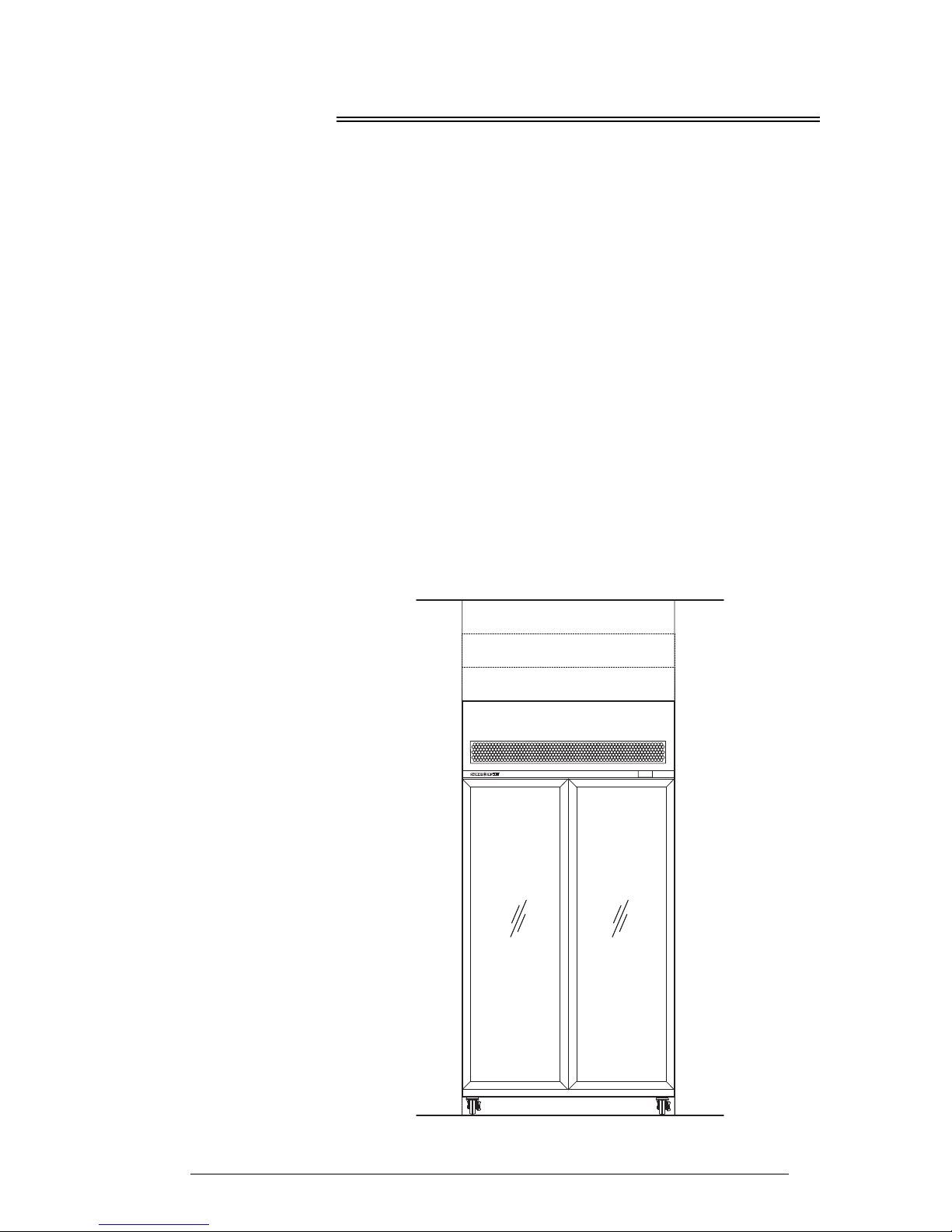
Ventilation See diagram below for ventilation guidelines. When positioning the freezer,
ensure there is at least a 200mm space above the top panel. Adequate
ventilation around the refrigeration unit is essential for efficient operation.
The air surrounding the refrigeration unit must not exceed 40°C. Keep the
ventilation slots at the top of the cabinet clear at all times and never store
cardboard cartons or other objects on top of the freezer.
Note: Remote cabinets require a minimum of 300mm clearance above the
top panel to allow for service access.
Requires min. 400mm
space above top panel
Requires min. 300mm
space above top panel
Requires min. 200mm
space above top panel
35°C to 40°C
ambient
25°C to 35°C
ambient
Less than 25°C
ambient
All remote
cabinets
Page 6

6
Installation
User Manual
SKOPE VF Series
Shelves
The freezer is supplied with five wire shelves which may be positioned at
different heights to suit various products. Always ensure that the shelf clips
are securely engaged in each of the shelf support strips. Support strips are
marked ‘+’ for easy location of shelf clips.
To fit the wire shelves
Optional Door Lock
Cabinets fitted with optional door locks have a key barrel type lock at the top
each door. Use the supplied keys to lock and unlock the door as necessary.
1. Unpack the shelves and shelf clips from inside the cabinet.
2. Establish the desired position for the shelves and securely engage a shelf
clip in each of the shelf support strips.
3. Sit the shelves on the
shelf clips.
4. The ticket strips clip into
place on the front of each
shelf.
Page 7

7
SKOPE VF Series
Operation
User Manual
2 Operation
Automatic Start-Up
After the cabinet has been positioned in a suitable place, plug it in an d c heck
the following activity.
Loading Product
Let the freezer run for 30 minutes before loading it with product the first time.
When loading the freezer:
Allow adequate air space around each item to ensure even cooling and
efficient operation of the freezer.
Do not exceed a maximum load of 20kg per shelf.
Remove some product if the shelves are flexing.
Do not let anything overhang the shelves because this might stop the
doors from shutting or even break something.
Do not load product above the load limit indicators shown on the cabinet
interior sides (see image below).
Item Activity
Condenser Fan
The condenser fan starts and runs at a slow speed. When the
compressor starts, the condenser fan will run at full speed.
Lighting
The lights that illuminate cabinet interior and top sign (where
applicable) will come on when the freezer is turned on. The
light/s can be switched on and off via the electronic controller
(see over page). Cabinets fitted with solid doors use an
automatic light switch to turn the light on and off with door
openings.
Electronic
Controller
An electronic controller runs the freezer and is visible on the
control panel above the door/s. The electronic controller
display panel shows the cabinet temperature.
Note: Twin unit freezers are fitted with two electronic
controllers, one for each refrigeration unit. Only one electronic
controller is visible.
Compressor
The compressor starts about one minute after the lights go on.
The compressor turns off when the product temperature
reaches around -21°C and turns on again when it reaches
about -18°C.
Evaporator Fan
The evaporator fan will not operate until the evaporator probe
senses a temperature of -8°C on the evaporator coil. When
the evaporator coil is below -8°C, the evaporator will run at
slow speed or fast speed as required.
LOAD LIMIT
Page 8

8
Operation
User Manual
SKOPE VF Series
Electronic Controller
Introduction The electronic controller controls the freezer, displays the freezer
temperature and signals temperature alarms. It uses temperature probes to
collect data and runs the freezer accordingly. The electronic controller is
pre-programmed and usually requires no initial setup or additional
programming. SKOPE does not recommend that the settings be changed
unless necessary.
Note: Twin unit freezers freezers are fitted with two electronic controllers,
one for each refrigeration unit.
Faceplate Because the electronic controller plays such an important role, it’s helpful to
know the parts of the faceplate you may use.
No. Item Description
1
Prg / mute: To initiate program sets, press for 5 seconds. Mutes the audible alarm (buzzer).
2
UP / aux: To switch light/s on and off. To scroll settings UP (in program mode).
3
Set: If pressed for more than 2 seconds displays and / or enables changing the temperature
setpoint (see page 9).
4
DOWN / def: To scroll settings DOWN (in programme mode).
5
COMPRESSOR: ON when the compressor and condenser fan starts. Flashes when activation of
the compressor is temporarily delayed.
6 FAN: Shows when fan is operational.
7
DEFROST: ON when the defrost is activated. Flashes when the activation of the defrost is
temporarily delayed due to procedures in progress.
8 AUX: n.a.
9 ALARM: Flashes in the event of alarms.
10 CLOCK: On when real time clock is enabled.
11 LIGHT: On when the cabinet lighting is activated.
12 SERVICE: Flashes in the event of malfunctions.
13 DISPLAY: Shows the cabinet temperature.
14 HACCP: n.a.
15 CONTINUOUS CYCLE: On when freezer is running in continuous run mode.
Page 9

9
SKOPE VF Series
Operation
User Manual
Defrost To ensure efficient operation, the electronic controller forces a defrost cycle
when required. During a defrost cycle, the compressor stops, DEF and the
will display on the electronic controller faceplate. The freezer will resume
normal operation once the defrost cycle has finished. A manual defrost can
also be initiated by pressing and holding the
button.
Continuous
Cycle
The continuous cycle can be used to pull down the temperature of product
inside the freezer quickly. During a continuous cool down the compressor
runs continuously for a set time.
To start a continuous cycle
To stop a continuous cycle
Temperatur e
Setpoint
The VF Freezer Range is manufactured with a pre-set control temperature
set point of -21°C. If this set point does not match your required storage
temperature it is recommended that you change the set point accordingly.
The set point can be adjusted between -26°C and -16°C.
To view and adjust the temperature setpoint
1. While the freezer is switched on and
running, press and hold the and
buttons for five seconds.
The symbol will display during a
continuous cycle.
1. The electronic controller will
automatically stop the continuous cycle
after a period of time.
The continuous cycle can be stopped
by pressing and holding the and
buttons for five seconds.
1. To view the setpoint: press and hold the
key for 2 seconds, until the
setpoint value flashes
2. To adjust the setpoint: press either the
and keys to display the
required setpoint value.
3. Press the key again to memorise
the new setpoint value. If this is not
done within 60 seconds, changes will
be lost and you will need to repeat the
above procedure.
Page 10

10
Operation
User Manual
SKOPE VF Series
Controller
Reset
To delete program modifications and reset the controller to SKOPE default
program or when a replacement controller is being fitted, a ‘Controller Reset’
must be performed.
To reset the controller
1. Disconnect the freezer from the power supply.
2. Press and hold the key while
plugging the freezer into the power
supply (this may require two people).
After a few seconds the controller is
reset and program mode ‘bn0’ is
displayed. The controller must never be
left in program mode ‘bn0’ as failure
will occur.
3. Press the or keys to select
‘bn1’ for SKOPE default program.
4. Immediately press the key to
confirm the preferred program. If not
confirmed within 60 seconds the
freezer will remain in program mode
‘bn0’ (and cause failure). If this occurs,
repeat the above procedure.
Page 11

11
SKOPE VF Series
Operation
User Manual
Alarms The following table explains messages that the electronic controller displays
and related alarms. Alarms signal unexpected operational changes in the
freezer and stop when action is taken to resolve the problem.
Code Display
Icon
Alarm
Description
Initial Action
Flashing
Product HIGH
temperature
alarm
1. Check the cabinet product loading to ensure
ventilation slots are not blocked and that product
does not overhang the shelves.
2. Ensure the cabinet is installed with good
refrigeration unit ventilation.
3. Check and clean the condenser coil (see
page 12).
4. Unplug cabinet from the power supply for 1
minute, then reconnect to power supply.
If problems persist, contact SKOPE
Flashing
Product LOW
temperature
alarm
Door open
alarm
Check door is closed.
High ambient
alarm
Check ventilation and operating conditions (see
page 5).
High pressure
alarm
Check and clean the condenser coil (see page 12).
Flashing
Control probe
fault
Contact an authorised service agent to replace
probe.
Flashing
Evaporator
probe fault
Flashing
Ambient
probe fault
None
Defrost overtime limit
Unplug cabinet from the power supply for 1 minute,
then reconnect to power supply.
If problems persist, contact an authorised service
agent.
Flashing
Real-time
clock fault
Flashing
Controller E
prom error
Flashing
Controller E
prom error
None
Start defrost
request
None
None
End defrost
request
Page 12

12
Servicing
User Manual
SKOPE VF Series
3 Servicing
Cleaning
Ensure the freezer is disconnected from the power supply before cleaning.
Cabinet Periodically wipe the inside and outside of the cabinet with a damp cloth,
taking care to keep moisture away from electrical parts.
Condenser
Coil
To ensure trouble-free performance, we strongly urge monthly cleaning with
a soft brush to remove dust and fluff. A more thorough cleaning is
recommended every six months, by qualified service personnel. The
condenser coil must be kept clean for efficient and reliable operation.
To clean the condenser coil
WARNING
Twin unit freezers have two seperate power supplies. Ensure
both supplies are disconnected before undertaking any service
or maintenance work.
WARNING
Disconnect the freezer from the power supply before cleaning
the condenser coil.
1. Disconnect the freezer from the power supply.
2. Remove the sign assembly. Lift the assembly up and off the sign sides and if
necessary unplug it from the cabinet.
3. Clean the condenser coil
with a soft brush.
4. Refit the sign assembly and reconnect the freezer to the power supply.
Page 13

13
SKOPE VF Series
Servicing
User Manual
Lighting
This freezer is designed for use with LED tubes and is not compatible with
fluorescent tubes.
As with any maintenance, ensure the freezer is disconnected from the
power supply before cleaning.
Interior Light The cabinet interior is lit by one side light or one centre pillar light (see table
below for details), which can be replaced without moving shelves or
removing product.
Interior light specifications
To replace the cabinet interior side light (model VF650)
To replace the cabinet interior pillar light (model VF1000/1300/1500)
WARNING
Twin unit freezers have two seperate power supplies. Ensure
both supplies are disconnected before undertaking any service
or maintenance work.
IMPORTANT
DO NOT use fluorescent tubes.
Model LED Tube Specification
VF650 1 x side light: 22 Watt T8 LED tube (Ø26mm x 1500mm)
VF1000/VF1300 1 x pillar light: Twin 22 Watt T8 LED tube (Ø26mm x 1500mm)
VF1500 2 x pillar lights: Twin 22 Watt T8 LED tube (Ø26mm x 1500mm)
1. Disconnect the freezer from the power supply.
2. Remove the diffuser by squeezing it until it is released from the aluminium
housing, and then push the diffuser out of the way.
3. Rotate the LED tube until
the pins on the ends of the
tube align with the slots,
then slide it out.
4. Fit a new LED tube.
Ensure the LED tube is
fitted with the power end
at the top.
5. Refit the diffuser by slipping the back section into the housing, then
squeezing and snapping the front section of the diffuser into place as you
work down the length of the light.
1. Disconnect the freezer from the power supply.
2. Remove the diffuser by squeezing it until it is released from the housing, and
then push the diffuser out of the way.
3. Rotate the LED tube until the pins on the ends of the tube align with the slots,
then slide it out.
4. Fit a new LED tube. Ensure the LED tube is fitted with the power end at the
top.
Page 14

14
Servicing
User Manual
SKOPE VF Series
Sign Light Not as standard - lit sign freezers only. The sign unit is lit by one LED tube
(see table below for details) which can be replaced by removing the front
sign panel.
Sign light specifications
To replace the sign light
Model LED Tube Specification
VF650 1 x 9 Watt T8 LED tube (Ø26 x 600mm)
VF1000 1 x 12 Watt T8 LED tube (Ø26 x 900mm)
VF1300 1 x 20 Watt T8 LED tube (Ø26 x 1200mm)
VF1500 1 x 22 Watt T8 LED tube (Ø26 x 1500mm)
1. Disconnect the freezer from the mains power supply.
2. Remove the sign assembly. Lift the assembly up and off the sign sides and
unplug it from the cabinet.
3. Seperate the light sign
light assembly from the
sign panel by undoing the
two fixing screws on each
side of the sign panel.
4. Remove the top of the
sign light assembly by
undoing the four fixing
screws on the top of the
sign light assembly.
5. Remove the plastic sign panel (and artwork if present) from the sign light
assembly.
6. Rotate and remove the
failed LED tube.
7. Fit the new LED tube.
8. Refit the clear front panel (and artwork if present) and screw the sign top
cover back onto the top of the sign assembly.
9. Refit and fix the sign light back onto the sign panel assembly.
10. Plug the sign assembly back into the cabinet and slot the assembly back
onto the sign sides.
Page 15

15
SKOPE VF Series
Servicing
User Manual
Troubleshooting
For questions about the electronic controller, see page 11. For problems
with the cabinet and refrigeration cassette, use the following table.
Problem Possible Cause Suggestions
• Cabinet not
operating
• No controller display
• Loss of power
supply
• Check mains power supply.
• Interior light not on • Failed LED tube • Replace LED tube (see
page 13).
• Blown cabinet fuse • Contact an authorised
service agent to replace it.
• Power consumption
is higher than
expected
• Unit operating too
hot
• Clean the condenser coil
(see page 12).
• Ensure the cabinet has
good ventilation around the
refrigeration unit (see
page 5).
• Ensure the cabinet is in a
cool spot.
• Cabinet doors are
opened excessively
• Ensure doors are closed
more often.
• Product is too warm • Restricted airflow to
cabinet
• Ensure product is not
blocking airflow slots.
• Ensure there is space
around individual product
pieces.
• Warm cabinet
temperatures
• Compressor
operating for long
periods (more than 1
hour)
• Blocked condenser • Clean the condenser coil
(see page 12).
• Poor ventilation
around refrigeration
unit
• Ensure the cabinet has
good ventilation around the
refrigeration unit (see
page 5).
Page 16

SKOPE Contacts
SKOPE Industries Limited
NEW ZEALAND CONTACT
Head Office
PO Box 1091, Christchurch
New Zealand
Freephone: 0800 947 5673
Fax: (03) 983 3896
E-mail: enquiry@skope.co.nz
Website: www.skope.co.nz
AUSTRALIAN CONTACT
A.B.N. 73 374 418 306
PO Box 7543, Baulkham Hills B.C.
NSW 2153, Australia
Freephone: 1800 121 535
Fax: 1800 121 533
E-mail: enquiry@skope.com.au
Website: www.skope.com.au
Trademark Infringement
The SKOPE trademark on this product is infringed if the owner, for the time being, does
any of the following:
• Applies the trade mark to the product after their state, condition, get-up or packaging
has been altered in any manner
• Alters, removes (including part removal) or obliterates (including part obliteration) the
trade mark on the product
• Applies any other trade mark to the product
• Adds to the product any written material that is likely to damage the reputation of the
trade mark
Notice of the above contractual obligations passes to:
• Successors or assignees of the buyer
• Future owners of the product
VF Series
SKOPE Vertical Freezer
User Manual
MAN10521
Rev. 3.3 Jun. 2016
© 2012 SKOPE Industries Limited. All rights reserved.
SKOPE Industries Limited reserve the right to alter specifications without notice.
is a registered trademark of SKOPE Industries Limited.
 Loading...