

Page 1

TMEF Series
User Manual
MAN10132 Rev. 1.0 Oct. 2010
SKOPE Vertical Freezer
Page 2

TMEF Series
SKOPE Vertical Freezer
Type: (CAREL ir32 Controller)
User Manual
MAN10132
Rev. 1.0 Oct. 2010
© 2010 SKOPE Industries Limited. All rights reserved.
SKOPE Industries Limited reserve the right to alter specifications without notice.
is a registered trademark of SKOPE Industries Limited.
SKOPE INDUSTRIES LIMITED
Head Office
PO Box 1091, Christchurch
New Zealand
Freephone: 0800 947 5673
Fax: (03) 983 3896
E-mail: enquiry@skope.co.nz
Website: www.skope.co.nz
Trademark Infringement
The SKOPE trademark on this product is infringed if the owner, for the time
being, does any of the following:
• Applies the trade mark to the product after their state, condition, get-up or
packaging has been altered in any manner
• Alters, removes (including part removal) or obliterates (including part
obliteration) the trade mark on the product
• Applies any other trade mark to the product
• Adds to the product any written material that is likely to damage the
reputation of the trade mark
Notice of the above contractual obligations passes to:
• Successors or assignees of the buyer
• Future owners of the product
Page 3

SKOPE TMEF Series
User Manual
iii
CONTENTS
1 Installation
Safety First . . . . . . . . . . . . . . . . . . . . . . . . . . . . . . . . . . . . . . . . . . . . . 4
Positioning the Cabinet . . . . . . . . . . . . . . . . . . . . . . . . . . . . . . . . . . . . 5
Before Operating. . . . . . . . . . . . . . . . . . . . . . . . . . . . . . . . . . . . . . . 5
Power Cord . . . . . . . . . . . . . . . . . . . . . . . . . . . . . . . . . . . . . . . . . .5
Cabinet Location . . . . . . . . . . . . . . . . . . . . . . . . . . . . . . . . . . . . . . . 5
Ventilation . . . . . . . . . . . . . . . . . . . . . . . . . . . . . . . . . . . . . . . . . . . . 6
Shelves . . . . . . . . . . . . . . . . . . . . . . . . . . . . . . . . . . . . . . . . . . . . . . 6
2 Operation
Automatic Start-Up . . . . . . . . . . . . . . . . . . . . . . . . . . . . . . . . . . . . . . . 7
Loading Product . . . . . . . . . . . . . . . . . . . . . . . . . . . . . . . . . . . . . . . . . 7
CAREL Electronic Controller . . . . . . . . . . . . . . . . . . . . . . . . . . . . . . . . 8
Faceplate . . . . . . . . . . . . . . . . . . . . . . . . . . . . . . . . . . . . . . . . . . . . 8
Operation . . . . . . . . . . . . . . . . . . . . . . . . . . . . . . . . . . . . . . . . . . . . 9
Controller Components . . . . . . . . . . . . . . . . . . . . . . . . . . . . . . . . . 9
Defrost . . . . . . . . . . . . . . . . . . . . . . . . . . . . . . . . . . . . . . . . . . . . . . 9
Alarms and Signals . . . . . . . . . . . . . . . . . . . . . . . . . . . . . . . . . . . 10
Programming . . . . . . . . . . . . . . . . . . . . . . . . . . . . . . . . . . . . . . . .10
Setpoint . . . . . . . . . . . . . . . . . . . . . . . . . . . . . . . . . . . . . . . . . . . . 10
Manual Defrost . . . . . . . . . . . . . . . . . . . . . . . . . . . . . . . . . . . . . . . 10
Continuous Refrigeration . . . . . . . . . . . . . . . . . . . . . . . . . . . . . . . 10
Display Function . . . . . . . . . . . . . . . . . . . . . . . . . . . . . . . . . . . . . .10
Buzzer Off . . . . . . . . . . . . . . . . . . . . . . . . . . . . . . . . . . . . . . . . . . 10
Parameters . . . . . . . . . . . . . . . . . . . . . . . . . . . . . . . . . . . . . . . . . . 11
Parameter Modification (if keypad is enabled) . . . . . . . . . . . . . . .12
3 Servicing
Cleaning . . . . . . . . . . . . . . . . . . . . . . . . . . . . . . . . . . . . . . . . . . . . . . 13
Cabinet . . . . . . . . . . . . . . . . . . . . . . . . . . . . . . . . . . . . . . . . . . . . . 13
Condenser Coil . . . . . . . . . . . . . . . . . . . . . . . . . . . . . . . . . . . . . . 13
Lighting . . . . . . . . . . . . . . . . . . . . . . . . . . . . . . . . . . . . . . . . . . . . . . . 14
Interior Side Light . . . . . . . . . . . . . . . . . . . . . . . . . . . . . . . . . . . . . 14
Centre Pillar Light . . . . . . . . . . . . . . . . . . . . . . . . . . . . . . . . . . . . . 14
Page 4
4
Installation
User Manual
SKOPE TMEF Series
1 Installation
Safety First Always observe safety precautions when using any electrical appliance.
Read these instructions carefully and retain them for future reference.
When the appliance is used by or near young children or infirm persons,
close supervision is necessary, especially to ensure children do not play
with it.
Do not use this appliance for other than its intended use.
Do not cover the grilles or block the entry or exhaust of airflow by
placing objects up against the refrigeration freezer unit.
Do not probe any opening.
Only use this appliance with the voltage specified on the cabinet rating
label affixed to the refrigeration unit.
Ensure the freezer has adequate ventilation as this is essential to
economical, high performance.
Be careful not to touch moving parts and hot surfaces.
For your own safety and that of others, ensure that all electrical work is
done by authorised personnel.
If the power supply flexible cord becomes damaged, it must be replaced
by an authorised service agent or similarly qualified person in order to
avoid a hazard.
Ensure all necessary safety precautions are observed during installation
or removal of the refrigeration unit.
The freezer is not designed to be stable while in motion. Use extreme
caution when moving or transporting the freezer.
WARNING
The TMEF1500 (3 door) freezer has two seperate power
supplies.
CAUTION
Always isolate the cabinet from the power supply before
attempting any maintenance.
CAUTION
Never overload the power supply, which could damage the
chiller and product. See the rating label inside the cabinet for
the safe power supply and current draw.
Page 5
5
SKOPE TMEF Series
Installation
User Manual
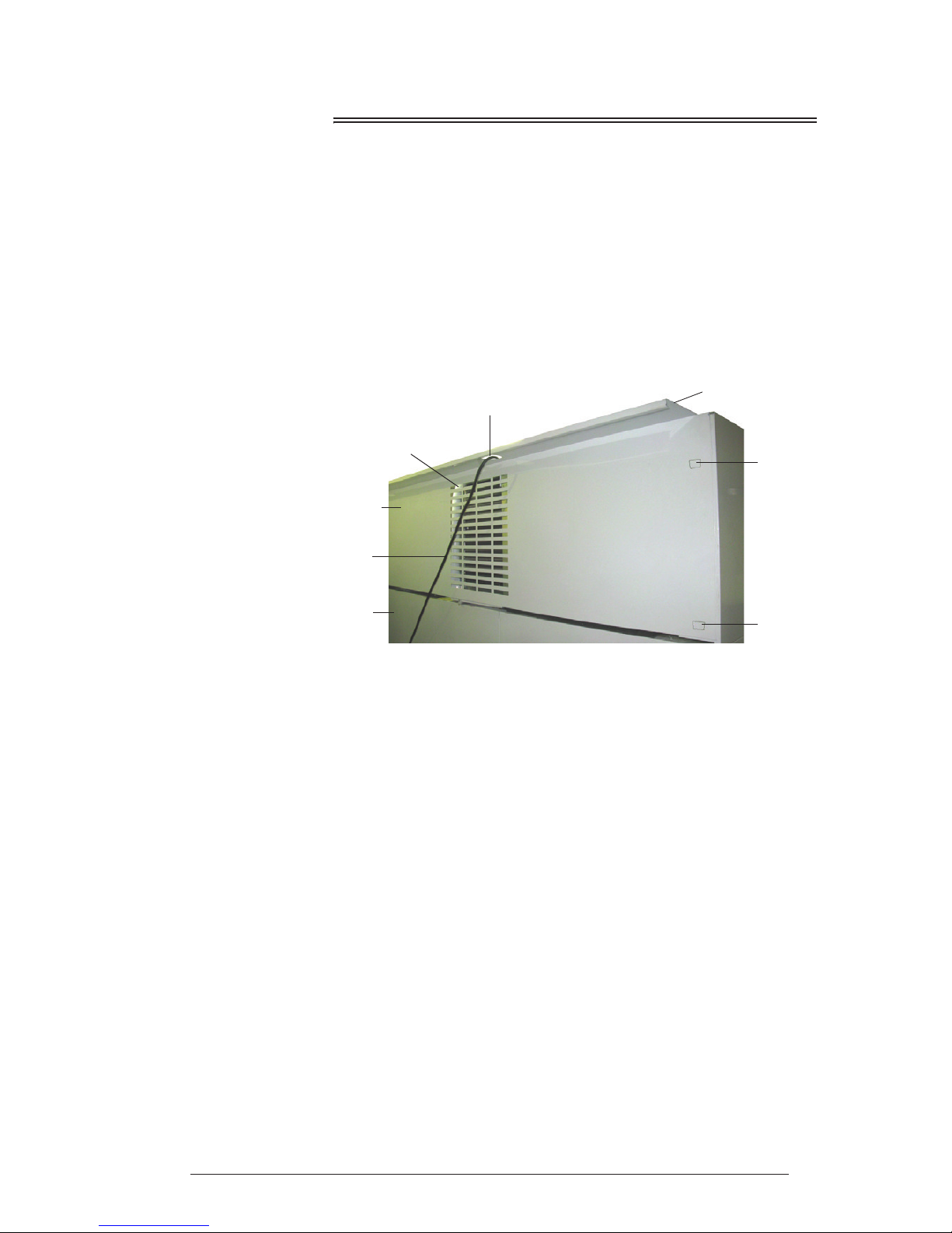
Positioning the Cabinet
Before
Operating
Follow the below steps to ensure the back sign panel is reversed and the
rear spacer is protruding from the back of the cabinet (TMEF1500 3 door
cabinet only). This will provide the necessary air gap at the rear of the
cabinet for correct operation.
1. Cut the cable ties securing the sign back panel to the sign side panels.
2. Reverse the sign back panel so that the rear spacer protrudes from the
rear of the cabinet, and attach the sign back panel to the cabinet by
hooking into the slots on the sign side panel ends.
3. Retrieve and unravel the power cords and fit through the exit holes on
top of the rear spacer.
Power Cord The freezer has a flexible power cord fitted with a 3-pin plug, which exits
from the top rear of the cabinet. Pull the power cord around so that it’s not
trapped before you position the cabinet.
Note: The TMEF1500 (3 door) freezer has two power cords, one for each
refrigeration unit.
Cabinet
Location
The location of the freezer may be the single most important decision that
will extend its life and ensure economical, high performance. We
recommend that you put the freezer in the coolest place possible because it
will use less power and last longer.
Avoid direct sunlight, warm draughts etc. Allow adequate space for doors to
open and close properly. Self-closing doors have internal torsion bars
pretensioned at the factory, and must be unobstructed. Ensure the cabinet
sits on a level surface so that the doors shut and correctly seal. Level footing
also prevents the condensate tray from overflowing.
Power Cord
Rear Spacer
Power Cord Exit Hole
Sign Back Panel
Back of Cabinet
Hanging
Hook/Slot
Hanging
Hook/Slot
Ventilation Slots
Page 6

6
Installation
User Manual
SKOPE TMEF Series
Ventilation Adequate ventilation is essential:
Ensure the is a minimum of 200mm of space above the cabinet and
100mm behind the cabinet.
Air onto the refrigeration unit should not exceed 25°C.
Do not cover any ventilation holes on the front and back of the freezer.
Ensure there is always at least a 200mm gap above the cabinet, and when
installing a TMEF1500 (3 door) cabinet a 100mm gap behind the cabinet
(see below). Keep the ventilation slots at the top of the cabinet clear at all
times, never store cardboard cartons or other objects on top of the freezer.
Shelves
Shelves may be positioned at different heights to suit various products.
Always ensure that the shelf clips are securely engaged in each of the shelf
support strips. Support strips are marked ‘+’ for easy location of shelf clips.
TMEF650/1000
TMEF1500
200mm min
200mm min 100mm min
Page 7

7
SKOPE TMEF Series
Operation
User Manual
2 Operation
Automatic Start-Up
After the cabinet has been positioned in a suitable place, plug it in and check
the following activity.
Loading Product
Let the freezer run 30 minutes before loading it with product the first
time.
Allow adequate air space around each item to ensure even cooling and
efficient operation of the chiller.
Do not exceed a maximum load of 20kg per shelf.
Leave airspace of at least 75mm (3”) above the product on the top shelf.
Do not cover air outlet at the bottom of the cabinet with product as this
may cause spot freezing of products and other products to be warm.
Remove some product if the shelves are flexing.
Do not let anything overhang the shelves because this might stop the
doors from shutting or even break something.
Item Activity
Condenser Fan
The condenser fan runs continuously throughout all
operations of the machine.
Lighting
The sign and interior lights turn on and stabilise after a few
flickers.
Electronic
Controller
An electronic controller runs the chiller and is visible
behind the front panel. The display panel first shows - - before stabilising on the cabinet temperature.
Compressor
The compressor starts about one minute after the lights go
on. The compressor should switch off when the cabinet
internal air reaches the preset ‘set point’ temperature.
Evaporator Fan
The evaporator fan which circulates the cabinet air will not
operate until the defrost probe senses a temperature of
-8°C. On initial start up the fan should come on after a
delay of approximately four minutes (verified by air blowing
out of the bottom duct and the green LED.
Page 8
8
Operation
User Manual
SKOPE TMEF Series
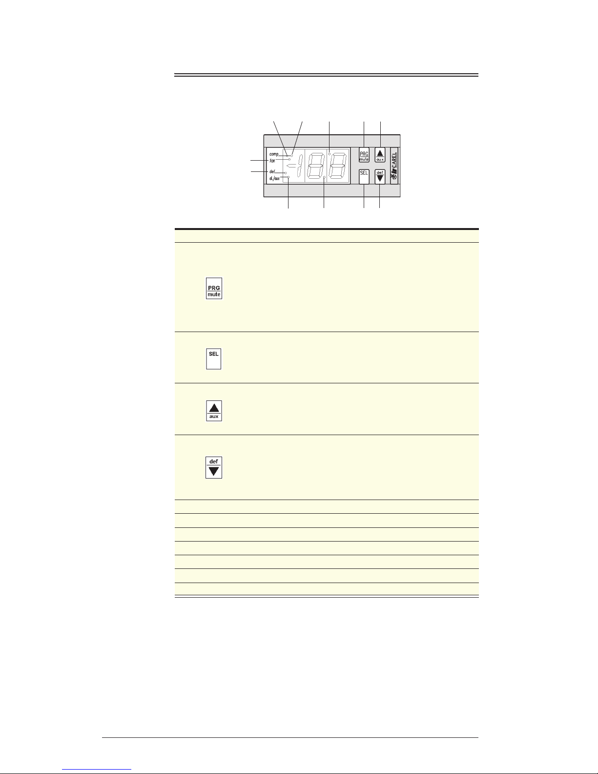
CAREL Electronic Controller
Faceplate
8
7
9
10
11
1 3
6
5 2
4
No. Item Description
1
Silences alarm buzzer.
Allows entry to frequent parameters section, if pressed for 5
seconds.
Allows entry to configuration parameters section, if pressed
simultaneously with ‘SEL’ for 5 seconds.
Locks in new parameters, and exits parameter sections.
Activates reset procedure.
2
Displays setpoint in run mode.
Displays selected parameter in parameter mode.
Allows entry to configuration parameters section if pressed
simultaneously with ‘PRG’ for 5 seconds.
3
Adjustment locked out
Alters parameters in parameter mode.
Activates and deactivates continuous refrigeration mode with ‘def’
key.
4
Adjustment locked out
Activates manual defrost cycle.
Alters parameters in parameter mode.
Activates and deactivates continuous refrigeration mode with ‘aux’
key.
5 Decimal point indicator.
6 Unused.
7 Defrost cycle on indicator
8 Evaporator fan on indicator.
9 Continuous refrigeration mode on indicator (fast freeze).
10 Compressor on indicator.
11 Remote controller indicator.
Page 9

9
SKOPE TMEF Series
Operation
User Manual
Operation The operation of this cabinet is controlled by a pre-programmed
microprocessor. The Microprocessor display indicates the temperature of
the cabinet ambient probe, except during a defrost where the temperature
of the cabinet probe is locked in, and during an alarm condition.
The display also has LED indicators showing the activation of the
compressor, the fan and the defrost. At alarm activation, the display
indicates the type of alarm signal; and an audible alarm sounds. The alarm
can be muted at the controller.
Controller
Components
A controlling probe located in a thermal mass inside the evaporator box,
called a ‘Cabinet Ambient Probe’.
An evaporator probe located within the evaporator coil, referred to as a
‘Defrost Probe’.
Defrost The first defrost will occur in 6 hours. During a defrost cycle (indicated by the
green defrost LED on the control panel) the compressor and the evaporator
fan will switch off. Four elements inside the evaporator box will then melt
away any ice build up. The duration of a defrost cycle depends on the
quantity of ice build up (usually about 10 minutes). A maximum of 22
minutes is preset. Defrost cycles are pre-programmed at 6 hour intervals.
During and after each defrost, the display will read the temperature detected
before the defrost cycle. The display will then show the return air
temperatures as the machine cycles during normal operation.
Defrosts should occur during off-peak periods to maximise the efficiency of
the machine. This can be achieved by switching the power off, then on
again, so that the subsequent 6 hourly cycle defrosts will not coincide with
peak periods.
Note:
A power cut would reset the defrost cycles.
This freezer has an over temperature cut-out inside the refrigeration unit
evaporator box. This is to safe guard the possibility of the defrost
elements remaining on under fault conditions (set at 55°C).
The light which illuminates the cabinet interior is permanently on, where
applicable.
Ensure the door gaskets form a good seal with the cabinet.
Component Description
Microprocessor: Located behind ventilated unit front cover.
Controller Relay Module: Located in control box. Performs processor
switching.
Module Connector Cable: Flat black cable connecting module to
microprocessor.
Probes: 2 x NTC probes are used.
Page 10

10
Operation
User Manual
SKOPE TMEF Series
Alarms and
Signals
Note: Alarm HI may activate during cabinets initial pull down cycle, after being first powered
up. Alarm may be muted; and will automatically reset when cabinet passes alarm setpoint.
Programming To access the controller
1. Press and hold PRG and SEL simultaneously for more than 5 seconds
until 00 is displayed.
2. Press aux (up) until 22 is displayed.
3. Press SEL to confirm selection. The first parameter /C is displayed.
To turn the controller keypad on
1. Follow Access / Entry above, until the first parameter /C is displayed.
2. Press def (down) two times, until H2 is displayed.
3. Press SEL to display the ‘value’ of the parameter.
4. Press aux (up) to increase or def (down) to decrease, until 01 is displayed.
5. Press SEL to accept the ‘value’.
6. Press PRG to lock in new value and to exit program.
Setpoint Press SEL key for 1 second and the ‘Setpoint’ will be displayed. On
releasing the key, the display will flash. To alter the ‘Setpoint’, press aux (up)
or def (down). Press SEL to lock in the value and return to cabinet
temperature.
Manual
Defrost
Follow steps above to access the controller, and press def (down) key for
more than 5 seconds to manually initiate a defrost.
Continuous
Refrigeration
Press aux (up) and def (down) together, (down key first) to initiate a
‘Continuous Refrigeration’ mode. The compressor will run without
interruption to the parameter ‘cc’ (6 hours: SKOPE programme). Its purpose
is to achieve a fast product pull-down.
Display
Function
During run mode, the display shows the value measured by the ‘Cabinet
Ambient Probe’. In alarm status, the display indicates the relative alarm
code.
Buzzer Off Press mute key to silence the buzzer. The alarm display remains while the
alarm condition exists.
Signal Description
EO on Indicates faulty ambient probe.
El blinking Indicates faulty defrost probe.
IA blinking
Indicates unit has high pressure fault.
Note: At alarm initiation, check condenser radiator for
blockage, and clean if necessary. To reset alarm, cabinet
must be replugged into power supply.
LO blinking Indicates low temperature alarm.
HI blinking Indicates high temperature alarm.
EA, EB or EE
blinking
Indicates data acquisition failure.
The controller requires re-programming.
Ed blinking Indicates defrost timed out.
Factory setting: -21°C
Maximum: -18°C
Minimum: -21°C
Page 11

11
SKOPE TMEF Series
Operation
User Manual
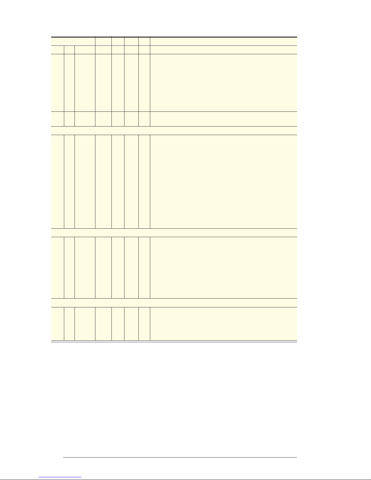
Parameters The following table describes SKOPE settings for CAREL controller
IR32POLBRO.
WARNING
The following parameters (Table 1: pp.10,11) are set exclusively for the SKOPE freezer
program, with its dedicated CAREL controller.
Any alteration from this program may adversely effect the operation of the freezer.
For full specifications, a detailed CAREL controller manual is available.
SKOPE Settings Type Min Max Def Parameter
PA 22 C 00 199 22 Password
Probe Parameters
/0 0
NTC
probe
n.a. 0 1 0
Type of probe used (NTC or PTC). Available after ‘Reset
Procedure’
/C 2.0 2°C F -20 20 0 Calibration offset for cabinet temperature display
/2 04 - C 1 15 4 Probe reading stability (lower the number, faster the response)
/3 08 - C 1 15 8 Probe reading speed (lower the number, slower the response)
/4 00 probe C 0 100 0 Designation as controlling probe
/5 00 °C C 0 1 0 Units of temperature measurement
/6 00 Yes C 0 1 0 Decimal point display
Cycle Parameters
rd 3.0 3°C F 0.1 20 2 Refrigeration differential
r1 -26 -26°C C -40 r2 -40 Minimum allowable setpoint
r2 -16 -16°C C r1 199 90 Maximum allowable setpoint
r3 01 Yes C 0 1 0
Enabling of ED alarm (defrost interrupted because maximum
duration has been reached, parameter dP) 0=No, 1=Yes
r4 3.0 3 C 0 20 3 Not used. Must be 3
r5 01 Yes C 0 1 0 Enabling of minimum / maximum temperature monitoring
rt - - F 0 199 - Actual interval in maximum / minimum temperature reading
rH - - F -50 +90 - Maximum temperature reading in the ‘rt’ interval
rL - - F -50 +90 - Minimum temperature reading in the ‘rt’ interval
Compressor Parameters
c0 01
1
minute
C 0 15 0 Compressor and evaporator fan start delay at power on
c1 03
3
minutes
C 0 15 0 Minimum time between compressor starts
c2 03
3
minutes
C 0 15 0 Minimum compressor OFF time
c3 00 0 C 0 15 0 Minimum compressor ON time
c4 99
99
minutes
C 0 100 0
Compressor backup for ‘Ambient’ probe failure (On for c4, off for
15 min)
cc 04 4 hours C 0 15 4 Duration of ‘Continuous Refrigeration Mode’
c6 02 2 hours C 0 15 2 Duration of alarm override after ‘Continuous Refrigeration Mode’
Defrost Parameters
d0 00 Electric C 0 1 0 Type of defrost
dl 06 6 hours F 0 199 8 Time interval between defrosts
dt 6 12°C F -40 199 4 Defrost termination temperature
dP 22
22
minutes
F 1 199 30 Maximum defrost time
Continued over page
Page 12
12
Operation
User Manual
SKOPE TMEF Series
* High Pressure trip is maintained as alarm status by latching relay. To reset, the freezer must be unplugged and then
replugged into the power supply.
Parameter Modification (if keypad is enabled)
1. Press aux (up) or def (down) to show the code of the parameter that has to be changed.
2. Press SEL to display the selected parameter value.
3. Press aux (up) or def (down) to increase or decrease the value.
4. Press SEL to temporarily confirm the new value, and display its code.
5. Repeat above procedures to alter further parameters.
Press PRG to lock in the new parameters and exit parameter modification procedure.
SKOPE Settings Type Min Max Def Parameter
d4 00 No C 0 1 0 Defrost at cabinet plug in
d5 00 No C 0 199 0 Defrost delay at cabinet plug in
d6 01 Yes C 0 1 1 Lock in temperature display during defrost
dd 03
3
minutes
F 0 15 2 Defrost drip time, before compressor and evaporator fan start
d8 01 1 hour F 0 15 1 Continuation of d6 at defrost end (until setpoint or d8 elapses)
d9 00 No C 0 1 0 Compressor protection times observed at defrost (c1, c2, c3)
d/ - - F n.a n.a n.a Evaporator temperature (via defrost probe) is displayed
dC 00
hrs /
mins
C 0 1 0 Time basis for parameter ‘dl’ and ‘dp’
Alarm Parameters
AO 1.0 1.0°C C 0.1 20 0.2 Alarm and fan differential
AL 10
-32°C /31°C
F 0 199 10 Low temp alarm (On=Setpoint -AL-A0) (Off=Setpoint -AL)
AH 09
-11°C /12°C
F 0 199 10 High temp alarm (On=Setpoint +AH+A0) (Off=Setpoint +AH)
Ad 60
60
minutes
C 0 199 120 Alarm delay time
A4 01 On C 0 5 0 Immediate external alarm i.e. High pressure switch trip*
A5 00 - C 0 5 0 Not used. must be 0
A6 99
99
minutes
C 0 100 0
Compressor run lock time due to A4 function. Compressor will
still cycle with HP switch
A7 00 - C 0 199 0 Not used. must be 0
Fan Parameters
F0 02 On C 0 1 0
Evaporator fan control type (controlled by Evaporator Defrost
Probe). Must be 2
F1
14.0-8°C /7°C
F 0 20 5
Evaporator fan start temperature (On=Setpoint +F1 -A0)
(Off=Setpoint +F1)
F2 00 No C 0 1 1 Evaporator fan off while compressor is off
F3 01 Yes C 0 1 1 Evaporator fan off during defrost
Fd 01
1
minute
F 0 15 1 Evaporator Fan delay after defrost
Other Selections
H0 00 - C 0 15 0 Serial address
H1 00 - C 0 1 1 Not used. Must be 0
H2 00 No C 0 3 1 Enable keypad & remote control (must be ‘01’ to enable)
H3 00 00 C 0 199 0 Password for remote control
Page 13
13
SKOPE TMEF Series
Servicing
User Manual
3 Servicing
Cleaning
Cabinet Periodically wipe the inside and outside of the cabinet with a damp cloth,
taking care to keep moisture away from electrical parts. As with any
maintenance, ensure the cabinet is disconnected from the power supply
before cleaning.
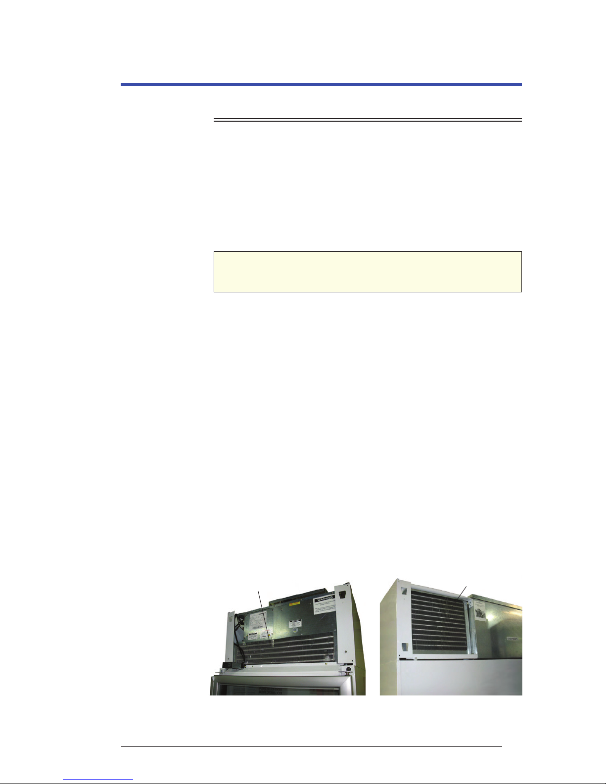
Condenser
Coil
To ensure trouble-free performance, we strongly urge monthly cleaning with
a soft brush to remove dust and fluff. A more thorough cleaning is
recommended every six months by qualified service personnel. The
condenser coil must be kept clean for efficient and reliable operation.
To clean the condenser coil
(TMEF650 single door & TMEF1000 2 door cabinets)
1. Disconnect the cabinet from the mains power supply.
2. Remove the top panel (above the doors) by releasing the sign clips
above the panel and unscrewing the 2 fixing screws. Lift up and out
from the cabinet.
3. Clean the condenser coil with a soft brush (see image below).
4. Carefully place the top panel back into position by hooking into the slots
on the sign side ends, repositioning the sign clips and fix in place with
the fixing screws.
To clean the condenser coil
(TMEF1500 3 door cabinet)
1. Disconnect both power cords from the mains power supply.
2. Remove the sign back panel lifting up and out from the cabinet.
3. Clean the condenser coil with a soft brush (see image below).
Note: The TMEF1500 (3 door) cabinet is fitted with two refrigeration
units, each with a condenser coil.
4. Carefully place the top panel back into position by hooking into the slots
on the sign side ends.
CAUTION
Disconnect the cabinet from the power supply before cleaning
the condenser coil.
TMEF650
TMEF150
Condenser Coil
Condenser Coil
Page 14

14
Servicing
User Manual
SKOPE TMEF Series
Lighting
Interior Side
Light
TMEF650 (single door) cabinet.
The cabinet interior is lit by one 58 Watt T8 fluorescent tubes (Ø26mm x
1150mm), which can be replaced without moving shelves or removing
product.
To replace the interior side light
1. Disconnect the cabinet from the power supply.
2. Remove the diffuser by squeezing it until it is released from the
aluminium housing, and then push the diffuser out of the way.
3. Rotate the fluorescent tube until the pins on the ends of the tube align
with the slots, then slide it out.
4. Fit a new fluorescent tube taking care that the printing on the tube is at
the bottom (tube orientation is important).
5. Refit the diffuser by slipping the back section into the housing, then
squeezing and snapping the front section of the diffuser into place as
you work down the length of the light.
Centre Pillar
Light
TMEF1000 (2 door) and TMEF1500 (3 door) cabinets.
The cabinet interior is lit by one or two 58 Watt T8 fluorescent tubes (Ø26mm
x 1150mm), which can be replaced without removing shelves or removing
product.
To replace the sign light
1. Disconnect the cabinet from the mains power supply.
2. Remove the top panel (above the doors) by unscrewing the fixing
screw/s and lifting up and out from the cabinet. Keeping all wires
attached, carefully place on top of the cabinet.
3. Unscrew the bottom fixing screw from the centre pillar cover and unclip
from the centre pillar.
4. Rotate the tube until the pins on the ends of the tube align with the slots,
then slide the tube out.
5. Fit the new fluorescent tube taking care that the printing on the tube is at
the bottom (tube orientation is important).
6. Refit the centre pillar cover by clipping back onto the centre pillar and
reattach the bottom fixing screw.
7. Carefully place the top panel back into position by hooking into the slots
on the sign side ends and reattach the fixing screw.
Flourescent Tube
Centre Pillar Cover
Centre Pillar
Page 15

15
SKOPE TMEF Series
Servicing
User Manual
New Zealand Contact
SKOPE INDUSTRIES LIMITED
Head Office
PO Box 1091, Christchurch
New Zealand
Freephone: 0800 947 5673
Fax: (03) 983 3896
E-mail: enquiry@skope.co.nz
Website: www.skope.co.nz
Australian Contact
SKOPE AUSTRALIA PTY LTD
A.C.N. 000 384 270
PO Box 7543, Baulkham Hills B.C.
NSW 2153, Australia
Freephone: 1800 121 535
Fax: 1800 121 533
E-mail: enquiry@skope.com.au
Website: www.skope.com.au
SKOPE Contacts
 Loading...