

Page 1
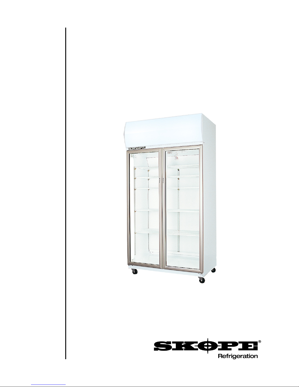
SK1000
SKOPE Top Mounted Two Door Chiller
Vertical Display and Storage
Operating and Service Manual
MAN0712 Rev. 1.0 Dec. 2003 edition
Page 2

Page 3
SK1000
SKOPE Top Mounted Vertical Chiller
Designed and Manufactured by
New Zealand
SKOPE INDUSTRIES LIMITED
PO Box 1091, Christchurch
New Zealand
Freephone: 0800 947 5673
Fax: (03) 983 3896
E-mail: enquiry@skope.co.nz
Website: www.skope.co.nz
Australia
SKOPE AUSTRALIA PTY LTD
A.C.N. 000 384 270
PO Box 7543, Baulkham Hills B.C.
NSW 2153, Australia
Freephone: 1800 121 535
Fax: 1800 121 533
E-mail: enquiry@skope.com.au
Website: www.skope.com.au
CONTACT ADDRESSES
i
Page 4
SK1000
SKOPE Top Mounted Vertical Chiller
SK1000
Operating and Service Manual
MAN0712
Rev. 1.0 Dec. 2003 edition.
Published by
SKOPE Industries Limited,
Christchurch, New Zealand.
Copyright © 2003
SKOPE Industries Limited.
All rights reserved.
SKOPE and CYCLONE are
registered trademarks of
SKOPE Industries Limited.
SKOPE Industries Limited
reserve the right to alter specifications
without notice.
ii
Page 5

SK1000
SKOPE Top Mounted Vertical Chiller
1 SPECIFICATIONS
1.1 Cabinet and Refrigeration Unit . . . . . . . . . . . . . . . . . . . . . . .6
2INSTALLATION
2.1 Positioning of Machine . . . . . . . . . . . . . . . . . . . . . . . . . . . . .7
3 OPERATION
3.1 Safety Information . . . . . . . . . . . . . . . . . . . . . . . . . . . . . . . . . 8
3.2 Operation of Machine . . . . . . . . . . . . . . . . . . . . . . . . . . . . . .9
3.3 Loading . . . . . . . . . . . . . . . . . . . . . . . . . . . . . . . . . . . . . . . . .9
3.4 Cleaning . . . . . . . . . . . . . . . . . . . . . . . . . . . . . . . . . . . . . . .10
3.5 Servicing . . . . . . . . . . . . . . . . . . . . . . . . . . . . . . . . . . . . . . .10
4 SERVICE INSTRUCTIONS
4.1 Interior Side Light . . . . . . . . . . . . . . . . . . . . . . . . . . . . . . . . 11
4.2 Glass Doors. . . . . . . . . . . . . . . . . . . . . . . . . . . . . . . . . . . . .12
4.3 Solid Doors . . . . . . . . . . . . . . . . . . . . . . . . . . . . . . . . . . . . .15
4.4 Sign Unit . . . . . . . . . . . . . . . . . . . . . . . . . . . . . . . . . . . . . . .16
4.5 Refrigeration Unit. . . . . . . . . . . . . . . . . . . . . . . . . . . . . . . . .19
4.6 Pressure Temperature Chart . . . . . . . . . . . . . . . . . . . . . . . . 24
4.7 Trouble Shooting Chart . . . . . . . . . . . . . . . . . . . . . . . . . . . .25
5 WIRING DIAGRAM
5.1 Model: SK1000 . . . . . . . . . . . . . . . . . . . . . . . . . . . . . . . . . .30
6 SPARES
6.1 Cabinet Assembly . . . . . . . . . . . . . . . . . . . . . . . . . . . . . . . .32
6.2 Interior Side Light . . . . . . . . . . . . . . . . . . . . . . . . . . . . . . . .33
6.3 Glass Door . . . . . . . . . . . . . . . . . . . . . . . . . . . . . . . . . . . . .34
6.4 Solid Door . . . . . . . . . . . . . . . . . . . . . . . . . . . . . . . . . . . . . .35
6.5 Illuminated Sign. . . . . . . . . . . . . . . . . . . . . . . . . . . . . . . . . .36
6.6 Refrigeration Unit. . . . . . . . . . . . . . . . . . . . . . . . . . . . . . . . .37
TABLE OF CONTENTS
iii
Page 6
6
SK1000
SKOPE Top Mounted Vertical Chiller
1.1 Cabinet and Refrigeration Unit
Cabinet Construction
Exterior/Interior: White powdercoat on galvanised steel
Insulation: 50mm thick, polyurethane foam
Cyclo-iso Pentane blowing agent: C
5H10/C5H12
Dimensions
Height: 2195mm - with standard castors fitted
Width: 1130mm
Depth: 700mm
Floor area:
0.79m
2
Internal volume: 980 litres
Refrigeration
Top mounted SKOPE Cyclone® refrigeration unit:
Nominal capacity: 820 Watts
Compressor: Danfoss SC12G
Refrigerant: R134a
Charge: 400 grams
Electrical
230-240 Volts a.c. 50 Hz, single phase power supply
Run Amps: 5.2 Amps
Lighting
2 x interior side lights: 58 Watt fluorescent tube, Ø26mm x 1524mm
Illuminated Sign
370mm high flat sign: 1 x 30 Watt fluorescent tube, Ø26 x 915mm
Doors
Self-closing, aluminium framed, double glazed, toughened safety glass
Shelves
Adjustable height, white powder coated, steel wire shelves
SPECIFICATIONS
1
Table 1: Specifications
Page 7

7
SK1000
SKOPE Top Mounted Vertical Chiller
2.1 Positioning of Machine
Mains Flex
The mains flex exits below the rear panel behind the refrigeration
units. For convenience, the flex should be retrieved before the
machine is positioned, when walls and partitions may make access
difficult.
Siting chiller
When siting the chiller, avoid direct sunlight, and warm draughts etc.
Adequate allowance should be made for door openings. The cabinet
must be positioned on a level surface for the door to shut and seal
correctly, and to prevent the condensate tray from overflowing.
Remove all packaging material from the shelves. Clip shelf support
brackets into the shelf support strips at the desired heights, and
relocate shelves.
Ventilation
When positioning the chiller, a gap must be left between the top of
the sign panels and ceiling, of at least 200mm. For efficient opera
tion of the chiller, it is essential that adequate ventilation be provided
above the refrigeration unit.
Maximum recommended operating
ambient temperature is 40°C.
Never store cardboard cartons or other items on top of the
refrigeration unit.
INSTALLATION
2
Page 8

8
SK1000
SKOPE Top Mounted Vertical Chiller
3.1 Safety Information
When using any electrical appliance, safety precautions should
always be observed. Read these instructions carefully, and retain for
future reference.
Warning:
Do NOT overload power supply.
Machine rated at 5.2 Amps @ 240 Volts
• Do not use this appliance for other than its intended use.
• Only use this appliance with voltage specified on the rating label.
• Ensure adequate ventilation of SKOPE refrigeration unit.
• Condenser coil MUST be kept clean. To ensure trouble free
performance, it is recommended that on a regular basis the unit
be isolated from the power supply and a vacuum cleaner used to
remove dust and fluff from the condenser.
• Be careful not to touch moving parts.
• Do NOT cover the grilles or block the entry or exhaust of airflow
by placing objects up against or on top of refrigeration unit.
• Do NOT probe any opening.
• Regulations require that all electrical work be carried out by
authorised persons. For your own safety and that of others,
ensure this is done.
• If the refrigeration unit is required to be installed or removed
from the cabinet, ensure all necessary safety precautions are
observed.
Caution:
Disconnect the cabinet from mains power supply before
attempting any electrical servicing, cleaning or maintenance.
OPERATION
3
Page 9

9
SK1000
SKOPE Top Mounted Vertical Chiller
3.2 Operation of Machine
Plug in machine and check operation of the refrigeration unit,
illuminated sign, and cabinet lights. The compressor, evaporator and
condenser fans should all operate initially. This may be verified by
listening for compressor switch-on, and by checking air movement
around the refrigeration unit and out of the rear duct inside the
cabinet.
Checking Operation
• Compressor and condenser fan should switch off when cabinet
internal temperature reaches approximately +1°C, and on again
at approximately +4°C. The internal cabinet air will continue to
circulate at all times.
• The lights which illuminate the top sign and cabinet interior are
permanently on.
• Ensure the door gaskets form a good seal with the cabinet.
3.3 Loading
Shelves may be positioned at different heights to suit various products. Always ensure that the shelf clips are securely engaged in
each of the four shelf support strips. Support strips are marked ‘+’
for easy location of shelf clips.
Product
For even cooling and efficient operation, allow air space around
packages etc. Do not allow products to overhang the front of the
shelf as this could prevent the door from shutting or cause glass
breakage. Leave an airspace of at least 75mm (3") above packages
etc. on the top shelf.
OPERATION
3
Page 10

10
SK1000
SKOPE Top Mounted Vertical Chiller
3.4 Cleaning
When necessary, wipe both the interior and exterior of the cabinet
with a damp cloth. Ensure the cabinet is disconnected from the
mains power supply before cleaning. The exterior of the cabinet may
be waxed with automobile polish for extra protection.
Do not wipe the sealant off the door gaskets, as the sealant ensures
the door gaskets form a good seal with the cabinet.
Periodic cleaning of the condenser coil is also recommended.
Condenser Coil
The condenser coil MUST be kept clean for efficient and reliable
operation. Clean the condenser coil with a brush and vacuum
cleaner regularly.
Access to the condenser coil is gained by removing the sign unit.
See page 16 for instructions on how to remove the sign unit.
The preventative maintenance recommendation is to clean the
condenser at one to three month intervals. Certain conditions may
necessitate more regular attendance, such as dusty, humid or
steamy environments.
Caution:
The cabinet MUST be disconnected from the mains power
supply before cleaning the condenser coil.
3.5 Servicing
Servicing should be carried out by an authorised service agent.
OPERATION
3
Page 11

11
SK1000
SKOPE Top Mounted Vertical Chiller
4.1 Interior Side Light
The fluorescent tube and starter are located inside the interior side
light, and may be replaced without removing shelves or product from
the cabinet. To replace the fluorescent tube and starter:
1. Disconnect cabinet from power supply.
2. Compress the back section of the diffuser, so that it disengages
from the aluminium housing and push the diffuser back, to gain
access to the light.
3. The fluorescent tube and starter can now be removed. Revolve
the tube until the pin position allows withdrawal.
4. Replace tube and starter as necessary (see p.33 for spares).
5. When refitting the diffuser, engage back section into side light
housing, and compress and snap front section of diffuser back
into place working progressively down the full length of light.
SERVICE INSTRUCTIONS
4
Tube Holder
Fluorescent Tube
Diffuser
Starter
COMPRESS
PUSH
Figure 1: Interior Side Light
Page 12

12
SK1000
SKOPE Top Mounted Vertical Chiller
4.2 Glass Doors
Alignment
Door alignment can be achieved by releasing the bottom hinge
bracket, which is provided with slots allowing alignment adjustment,
enabling the bottom of the door to be moved sideways.
Gasket replacement
The door gaskets clip into the door gasket retainer extrusion and
may be removed for repair or replacement simply by peeling from
frame, starting at a corner.
New gaskets, when fitted, may be lightly lubricated with a clear silicone grease or similar compound. This will lessen the possibility of
the gasket rolling. Should the gasket be out of shape when in place,
use hot air (i.e. from hair drier) to realign.
SERVICE INSTRUCTIONS
4
Figure 2: Door Gasket Removal
Door Gasket
Gasket Retainer
Door Frame
Page 13

13
SK1000
SKOPE Top Mounted Vertical Chiller
Glass Door tension
The glass door has an internal torsion bar, pretensioned at the factory, which enables the door to self-close. If necessary, door tension
can be further adjusted by rotating the capstan mounted in the
bottom hinge bracket. To adjust door tension:
1. Slowly release tension on the capstan, by turning the capstan
with a Ø2.5mm steel rod, and removing the split pin.
2. With the aid of another Ø2.5mm steel rod, increase the tension
by turning the capstan in the direction the door closes.
3. Once adequate tension has been achieved, re-insert the split
pin through the hole in the hinge bracket, to lock in position.
4. To check door tension; hold the door open approximately
100mm and let go of the door. The door should gently close,
with the door gasket forming an air tight seal with the cabinet.
In the event the door tension can no longer be adjusted, the torsion
bar may need replacing (see ‘Torsion bar replacement’, page 14).
SERVICE INSTRUCTIONS
4
Figure 3: Door Tension
Capstan
Split Pin
Ø2.5mm
steel rod
Bottom Hinge Bracket
Door
Door
alignment
adjustment
screw
Page 14

14
SK1000
SKOPE Top Mounted Vertical Chiller
Torsion bar replacement
The torsion bar assembly is located inside the door frame, and can
be replaced if necessary. To replace the door torsion bar assembly:
1. Remove the door from cabinet.
2. Carefully lever out the bottom bush from the door frame, and
pull old torsion bar out from the door frame. The end of the
torsion bar will need manoeuvring, to allow the ‘flat hook’ end to
clear the hinge hole.
3. Remove existing capstan and bush from old torsion bar.
4. Thread the capstan, complete with the bush, over the ‘round
hook’ end of the new torsion bar (see figure 4 below). Ensure
the aluminium tube
moves freely up and
down the torsion bar.
5. Fit the new torsion bar
assembly into the door
frame. When the torsion
bar is correctly installed,
the capstan should not
turn.
6. Lightly tap bottom of
capstan into hinge hole,
until the bush is flush with
door frame.
Refit the door to cabinet, and
adjust tension (see ‘Glass
Door Tension’, page 13).
SERVICE INSTRUCTIONS
4
Aluminium Tube
Figure 4: Torsion Bar Assembly
Torsion Bar
‘Round Hook’ end
Bush
Capstan
Page 15

15
SK1000
SKOPE Top Mounted Vertical Chiller
4.3 Solid Doors
Solid door removal
To remove the solid doors from the cabinet:
1. Remove bottom hinge screw from pivot point
2. Unbolt bottom hinge plate, and slide door down to remove from
top hinge.
Solid door tension
The solid door hinge mechanism has a preset tension, and is nonadjustable. Ensure the square notch in the hinge plate mates with
the door hinge, when replacing.
SERVICE INSTRUCTIONS
4
Solid Door Hinge
Bracket
Solid Door Hinge
Mechanism
Square
Locating
Notch
Bottom Hinge
Screw
Spring Stop
Washer (2)
Figure 5: Solid Door Hinge Mechanism
Page 16

16
SK1000
SKOPE Top Mounted Vertical Chiller
4.4 Sign Unit
The illuminated sign unit, located on top of the cabinet, houses a
fluorescent tube and electronic ballast. Internal access to the sign
unit may be gained with the sign unit still attached to the cabinet.
To replace Fluorescent Tube
To access the fluorescent tube, the curved sign panel must first be
removed from the sign unit. No tools are required for this procedure.
To remove the sign panel:
1. Disconnect cabinet from the power supply.
2. Start at one of the top corners of the sign unit and pull the sign
panel out from under the sign top cover (see figure 11 below).
3. Work along the length of the sign unit, pulling the sign panel out
as you go.
4. Carefully remove the sign panel away from the sign unit.
5. The fluorescent tube can now be accessed for replacement
(see figure 13, page 17).
SERVICE INSTRUCTIONS
4
Figure 12: Sign Corner Detail
Sign Top Cover
Corner Notch
Sign Panel
End Strip
Sign Panel
Figure 11: Removing Sign Panel
Sign Top Cover
Corner
Notch
Page 17

17
SK1000
SKOPE Top Mounted Vertical Chiller
To refit the curved sign panel:
1. Ensure both sign end strips are fitted to the sign panel.
2. Carefully fit the sign panel into the bottom sign cover, ensuring
the sign end strips are correctly positioned in both of the bottom
corner notches.
3. Locate one top corner of the sign panel into the corner notch of
the top cover. Ensure the end strip fits neatly into the corner
notch (see figure 12, page 16).
4. Use your thumbs to push the sign panel under the top cover,
working progressively along the full length of the panel. Ensure
the sign panel engages into the sign top along the full length of
the sign unit.
5. Ensure both the sign end strips fit neatly into the top and
bottom corner notches.
SERVICE INSTRUCTIONS
4
Figure 13: Sign Unit (with sign panel removed)
Fluorescent Tube
Sign Top Cover
Sign Panel
Sign ENSTO 3-pole Plug
Sign Unit
Centre Tie Wire
Sign Bottom Cover
Sign Panel
End Strip
Sign Wiring Cover
Page 18

18
SK1000
SKOPE Top Mounted Vertical Chiller
To remove Sign Unit
For ease of servicing, the sign unit can be removed from the cabinet.
To remove the sign unit:
1. Unplug the sign ENSTO 3-pole plug from the left hand end of
the unit junction box (see figure 17, page 33).
2. Loosen, and turn the sign retaining clip on the top of each side
panel (see figure 15, below).
3. Lift the sign unit up, to separate the sign from the sign sides.
4. The sign unit can now be removed from the cabinet.
To remove Sign Side Panels
For ease of servicing, the sign side panels can be removed from the
cabinet. To remove the side panels:
1. Remove the sign back panel, by lifting up to disengage from the
side and unit separation panels (see figure 16, below).
2. Loosen the keyhole screws, holding side panels to cabinet top.
3. Slide the side panels forward to disengage the keyholes.
SERVICE INSTRUCTIONS
4
Figure 15: Sign Retaining Clip
Figure 16: Sign Back Panel
Sign Retaining Clip
Sign Side Panel
Sign Back
Panel
Page 19

19
SK1000
SKOPE Top Mounted Vertical Chiller
4.5 Refrigeration Unit
The SKOPE Cyclone® unit is a self-contained refrigeration module,
which aligns with port holes on top of the cabinet. Air is drawn
through the evaporator and blown down the back duct. Air returns to
the evaporator through the roof port hole.
Condenser fan motor, evaporator fan motor, and thermostat may be
serviced with the refrigeration unit in place (see page 29 for spare
parts).
To provide easier access, the sign unit, side panels, and sign back
panel may be removed, and the refrigeration unit unbolted and shift
-
ed or removed completely.
SKOPE Refrigeration Unit Removal
1. Disconnect power supply from unit.
2. Remove sign unit and side panels (see page 18).
3. Undo bolt or screw at right hand side of the evaporator box,
then lift the complete unit to the right.
4. Turn unit until the lifting handles are facing the front.
5. The unit may now be removed from cabinet.
Caution:
The refrigeration unit weight is approximately 37kg. Ensure all
hazards are allowed for when removing unit.
Steps or platform about 1 metre high is suggested, to allow the
unit to be lifted, carried, and put down at about waist height.
Warning:
Avoid damage to the underside sealing strip, by not dragging
the unit. If damage to the seal occurs, it must be repaired prior
to re-installation.
SERVICE INSTRUCTIONS
4
Page 20

20
SK1000
SKOPE Top Mounted Vertical Chiller
Condenser Fan/Motor Replacement
1. Remove cover from control box, and withdraw the motor flex.
2. Undo two top screws from the mounting bracket, and remove
complete fan motor assembly (see page 37 for spare parts).
3. Remove securing cable ties if necessary.
Evaporator Fan/Motor Replacement
1. Undo four screws from the evaporator box lid, and remove lid
by lifting vertically.
2. Remove cover from the control box, and withdraw motor flex.
Carefully withdraw flex through the wall of evaporator box.
3. Undo two top screws from the mounting bracket, and remove
complete fan motor assembly (see page 37 for spare parts).
4. Ensure motor bracket is replaced in correct position.
5. On replacement, carefully reseal flex hole in evaporator box.
Thermostat Setting
The thermostat is pre-set to give an internal air temperature of
between 2°C and 4°C, and in normal circumstances should not
require adjustment. If thermostat adjustment is required: to make
colder - turn clockwise, to make warmer - turn anti-clockwise.
Thermostat Replacement
1. Undo the four screws from evaporator box lid, and remove lid
by lifting vertically.
2. Withdraw the capillary from evaporator, noting original position
and length into coil.
3. Remove the cover from control box, or undo the thermostat
bracket and remove thermostat (see page 37 for spare parts).
4. When refitting thermostat, ensure the capillary is fitted back in
the original position.
SERVICE INSTRUCTIONS
4
Page 21

21
SK1000
SKOPE Top Mounted Vertical Chiller
Recommended Service Procedures
SKOPE recommend the SKOPE Cyclone® demountability and
exchangeability philosophy, which in essence means:
The customer must not be inconvenienced during system
maintenance.
In the unlikely event of Refrigeration failure, an exchange unit is
simply swapped in a matter of minutes. There is no cabinet down
time or unloading product. In one 5 minute visit, the customer's
inconvenience ends. The faulty Cyclone® is then removed to the
workshop for repair as time allows.
For a suspected refrigerant problem
Disconnect the evaporator fan motor and with the system running, a
‘frost line’ will become obvious (after approximately 5 minutes):
Entire evaporator, accumulator, and suction line right up to compres
-
sor must be frosting. Compressor at suction inlet will sweat.
If these conditions are not met, the system is faulty, either short of
refrigerant, compressor not pumping efficiently, or capillary restric
tion. The system must then be opened (see Refrigerant R134a
Handling Precautions section) and gauges temporarily fitted (i.e.
either temporarily fit line piercing valves, or braze in service lines).
Short of refrigerant
Where the frosting effect is shorter than required (unless all refrigerant is lost, where there is no frosting effect). Only a small amount of
refrigerant will exit the system. A leak test (refrigerant / dry nitrogen
mix, up to 250 psig) should be performed to locate the leak. If no leak
is found, a pressure test should be performed (dry nitrogen only, up
to 250 psig) if there is no pressure drop over 24 hours, the fault
should be treated as a capillary restriction.
SERVICE INSTRUCTIONS
4
Page 22

22
SK1000
SKOPE Top Mounted Vertical Chiller
Compressor not pumping efficiently
Where the frosting effect is not as cold as it should be. Symptoms
include: compressor body hotter than normal, condenser cooler
than normal, and the compressor may make an unusual hissing
sound. All of these symptoms depend on the severity of the problem.
The only way to prove a pumping problem is to perform a compressor pump-down test: braze closed compressor suction line, Open
discharge line; then run the compressor to pull a vacuum on a vacu
um gauge. The compressor should pull down to approximately 30"
(inches) vacuum then turn the compressor off and this vacuum must
be held without any loss for 5 minutes. If the Compressor does not
pass these tests; it is not pumping efficiently and must be replaced.
There are different methods to proving pumping efficiency. If the test
is performed with a system charged with refrigerant, a deep vacuum
will not be achieved.
Capillary restriction
With a totally blocked capillary, there will be no refrigeration effect. A
partially blocked capillary may have similar symptoms to a system
being short of refrigerant. Flush a restricted capillary with dry nitro
-
gen. If the capillary will not clear, it must be replaced.
After the repair, the drier must be replaced (every time the refrigeration system is opened, the drier must be replaced). The Cyclone®
must be fully evacuated and charged to the volume of refrigerant
indicated on the Cyclone® serial/rating label. All service lines must
be purged.
Finally, pinch-off the gauge process lines (or remove line piercing
valves) and braze the system closed. SKOPE recommend against
leaving service valves in the system as these are prone to leak (and
are open to abuse). Perform a final system leak test.
SERVICE INSTRUCTIONS
4
Page 23

23
SK1000
SKOPE Top Mounted Vertical Chiller
Refrigerant R134a Handling Precautions
It is important to maintain dedicated HFC service equipment and
parts:
• Refrigeration gauges
• Service lines / Fittings
• Vacuum Pump
• Charging equipment
•Driers
• Compressors
• Temperature / Pressure chart
HFC (R134a) refrigeration systems require special service procedures because of the highly hygroscopic (moisture sensitive) polyolester (POE) compressor oil:
• The system (especially compressor) must only be open for the
very minimum time (to prevent moisture ingression). All parts
required for servicing must be at hand - before the system is
opened, and there should be no interruption until the system is
on the vacuum pump (or hermetically sealed).
• The system must not be open for longer than 20 minutes max.
• The drier must be replaced every time the system is opened.
• Clean work practices are essential.
• SKOPE recommend brazing the system closed after service - as
valves are prone to leak due to the nature of R134a.
Important:
Every time the refrigeration system is opened, the drier MUST be
replaced.
SERVICE INSTRUCTIONS
4
Page 24

24
SK1000
SKOPE Top Mounted Vertical Chiller
4.6 Pressure Temperature Chart
TEMPERATURE R134a R404A
°F °C KPa psig KPa psig
-29.2 -34 -32 9.4 71 10
-27.4 -33 -28 8.4 79 11
-25.6 -32 -25 7.3 86 13
-23.8 -31 -21 6.2 94 14
-22.0 -30 -17 5.0 103 15
-20.0 -29 -13 3.8 111 16
-18.4 -28 -9 2.6 120 17
-16.6 -27 -4 1.3 129 19
-14.8 -26 0 0.0 138 20
-13.0 -25 5 0.7 148 21
-11.2 -24 10 1.4 158 23
-9.4 -23 15 2.2 168 24
-7.6 -22 20 2.9 179 26
-5.8 -21 26 3.7 189 27
-4.0 -20 31 4.5 200 29
-2.2 -19 37 5.4 212 31
-0.4 -18 43 6.3 224 32
1.4 -17 49 7.2 236 34
3.2 -16 56 8.1 248 36
5.0 -15 63 9.1 261 38
6.8 -14 69 10.0 274 40
8.6 -13 77 11 .0 288 42
10.4 -12 84 12.0 302 44
12.2 -11 91 13.0 316 46
14.0 -10 99 14.0 331 48
15.8 -9 107 16.0 346 50
17.6 -8 116 17.0 361 52
19.4 -7 124 18.0 377 55
21.2 -6 133 19.0 393 57
23.0 -5 142 21.0 410 59
24.8 -4 151 22.0 427 62
26.6 -3 161 23.0 445 65
28.4 -2 171 25.0 463 67
30.2 -1 181 26.0 481 70
32.0 0 192 28.0 500 73
33.8 1 202 29.0 519 75
35.6 2 213 31.0 539 78
37.4 3 225 33.0 559 81
39.2 4 237 34.0 580 84
41.0 5 249 36.0 601 87
42.8 6 261 38.0 623 90
44.6 7 274 40.0 645 94
46.8 8 287 42.0 668 97
48.2 9 300 44.0 691 100
50.0 10 314 46.0 715 104
SERVICE INSTRUCTIONS
4
Table 2: Pressure Temperature Chart
Page 25

25
SK1000
SKOPE Top Mounted Vertical Chiller
4.7 Trouble Shooting
Complaint Possible Cause Repair
1. Cabinet not
operating
- lights etc not
going.
Loss of power supply. Check power supply.
High pressure switch cut-out, due to
over heating.
Check, and clean condenser.
Check unit operation, and reset
pressure switch (see p.7).
2. Compressor
will not start
- no hum.
Fuse removed or blown. No power. Replace fuse. Check reason.
Overload protector tripped. Refer to electrical section.
Thermostat stuck in open position. Repair or replace control.
Thermostat off, due to cold location. Relocate control.
Wiring improper, or loose. Check wiring against diagram.
3. Compressor
will not start
- hums but trips
on overload
protector.
Improperly wired. Check wiring against diagram.
Low voltage to unit. Determine reason and correct.
Start capacitor defective on CSIR or
CSR motor.
Determine reason and replace.
Run capacitor defective on PSC
motor.
Determine reason and replace.
Relay failing to close. Determine reason and correct.
Replace if necessary.
Compressor motor has a winding
open or shorted.
Check resistance values.
Replace compressor if necessary.
Internal mechanical trouble in compressor.
Replace compressor.
SERVICE INSTRUCTIONS
4
Table 3: Trouble Shooting Chart - continued on next page
Page 26

26
SK1000
SKOPE Top Mounted Vertical Chiller
4.7 Trouble Shooting
Complaint Possible Cause Repair
4. Compressor
starts, but
does not
switch off
- starts
winding.
Improperly wired. Check wiring against diagram.
Low voltage to unit. Determine reason and correct.
Relay failing to open, due to welded
contacts or relay incorrectly
mounted.
Determine reason and correct.
Replace if necessary.
Run capacitor defective on CSR
motor.
Determine reason and replace.
Excessively high discharge pressure.
Clean condenser. Check power
input. Possible overcharge,
insufficient condenser cooling,
or non-condensible gasses.
Compressor motor has winding open
or shorted. Check continuity and
resistance.
Replace compressor if faulty.
Internal mechanical trouble in compressor (tight). May be lubrication.
Replace compressor.
5. Compressor
starts and
runs, but
short cycles
on overload
protector
(relay may
chatter on
RSIR, CSIR
and CSR
motors).
Additional current passing through
overload protector.
Check wiring diagram. Check
for added fan motors etc.,
connected to wrong side of
protector.
Low voltage to unit. Determine reason and correct.
Overload protector defective. Check current, replace
protector.
Run capacitor defective on CSR
motor.
Determine reason and replace.
Excessive discharge pressure. Check condenser, check
ventilation, check for restrictions
in refrigeration system.
Suction pressure too high. Check for possibility of
misapplication.
Compressor too hot - insufficient
suction gas cooling.
Check refrigerant charge (fix
leak), add if necessary. Check
return vapour temperature and
suction superheat.
Comp’r motor has a winding shorted. Replace compressor.
SERVICE INSTRUCTIONS
4
Table 3: Trouble Shooting Chart - continued on next page
Page 27

27
SK1000
SKOPE Top Mounted Vertical Chiller
4.7 Trouble Shooting
Complaint Possible Cause Repair
6. Unit runs OK,
but short
cycles.
Overload protector. See section 4 on p.21.
Thermostat: requires adjustment or
incorrectly positioned.
Adjust or relocate thermostat.
Incorrect refrigerant charge. Adjust refrigerant charge.
7. Unit operates
long or continuously.
Unsatisfactory
cabine
t tem-
perature.
Short of refrigerant. Fix leak, and add charge.
Overcharge of refrigerant. Remove refrigerant to correct
charge.
Thermostat not cooling correctly. Adjust thermostat (clockwise
colder), and check thermostat
bulb location. If necessary,
replace thermostat.
Freezer has excessive load. Establish load within limits.
Evaporator coil iced. Defrost evaporator, check
refrigeration. Check
thermostat. Check door
closing, seals etc.
Restriction in refrigeration system. Determine location and clear
restriction. Flush with dry
nitrogen. Replace component
if blockage will not clear.
Dirty condenser. Clean condenser. Advise client
how to regularly clean
condenser.
Inadequate air circulation. Internal: Improve air
movement, alloe airflow around
stock.
External: Remove any
restrictions to condensing
ventilation.
Compressor not pumping
efficiently.
Replace compressor.
Filter dirty (if applicable). Clean or replace.
Faulty fan motor. Check rotation. Replace if
necessary.
SERVICE INSTRUCTIONS
4
Table 3: Trouble Shooting Chart - continued on next page
Page 28

28
SK1000
SKOPE Top Mounted Vertical Chiller
4.7 Trouble Shooting
Complaint Possible Cause Repair
8. Start capacitor
open, shorted
or blown.
Relay contact not opening
properly.
Clean contacts, or replace
relay if necessary.
Prolonged operation on start cycle
due to:
(a) Low voltage to unit.
(b) Improper relay.
(a) Determine reason and
correct.
(b) Replace relay.
Excessive short cycling. Determine reason for short
cycling (see section 5 on p.21),
and correct.
Improper capacitor. Determine correct size and
replace.
9. Relay defective
or burned out.
Incorrect relay. Check and replace.
Line voltage too high or too low. Determine reason and correct.
Excessive short cycling. Determine reason (see section
5 on p.21), and correct.
Relay being influenced by loose
vibrating mount.
Remount rigidly.
10. Suction line
frosted.
Evaporator fan not running. Determine reason and correct.
Overcharge of refrigerant capillary
systems.
Correct charge.
11. Unit noisy. Loose parts or mountings. Find and tighten.
Tubing rattle. Reform to be free of contact.
Bent fan blade causing vibration. Replace blade.
Fan motor bearing worn. Replace motor.
SERVICE INSTRUCTIONS
4
Table 3: Trouble Shooting Chart
Page 29

29
SK1000
SKOPE Top Mounted Vertical Chiller
Notes
SERVICE INSTRUCTIONS
4
Page 30

30
SK1000
SKOPE Top Mounted Vertical Chiller
5.1 Model: SK1000
WIRING DIAGRAM
5
Figure 8: SK1000 Wiring Diagram
Page 31

31
SK1000
SKOPE Top Mounted Vertical Chiller
5.1 Model: SK1000
Item Part Description
1 Mains Supply Flex
2 Sign Unit
3 30 Watt Fluorescent Tube
4 30 Watt Ballast
5 Starter (3)
6 Fused Connector Block with 3.0 Amp Fuse (2)
7 SKOPE Cyclone® Refrigeration Unit
8 Compressor - Danfoss SC12G
9 Relay
10 Start Capacitor
11 Control Box
12 Cabinet Heater Wire (optional)
13 Thermostat
14 RFI Suppression Capacitor
15 Terminal Block
16 Condenser Fan Motor
17 Evaporator Fan Motor
18 Socket Box
19 ENSTO Connector (2)
20 Control Panel
21 Connector Block (3)
22 58/65 Watt Ballast (2)
23 Side Light Assembly (2)
24 58 Watt Fluorescent Tube (2)
25 Centre Pillar Assembly
26 Centre Pillar Element
WIRING DIAGRAM
5
Page 32

32
SK1000
SKOPE Top Mounted Vertical Chiller
6.1 Cabinet Assembly
Part Description SKOPE Part Number
Control Panel V5050/789-32
Solid Centre Pillar Assembly E5064/L43-32
SKOPE Badge V5000/770BF-99
Wire Shelf V5000/583-32
Shelf Bracket V0973-99
Dial Thermometer V5000/95
Fused Connector Block ELZ6461
Fuse Holder ELZ6462
3.0 Amp Ceramic Fuse ELZ6467
58/65 Watt Ballast (for interior sidelight) ELZ8103
Swivel Castor SXX4339
SPARES
6
Page 33

33
SK1000
SKOPE Top Mounted Vertical Chiller
6.2 Interior Side Light
Part Description SKOPE Part Number
Side Light Assembly - L/H V5060/670L-32
Side Light Assembly - R/H V5060/670R-32
58 Watt Fluorescent Tube ELL6267
Side Light Diffuser V5060/E71
Starter ELZ2840
Lamp Holder ELZ6270
Lamp & Starter Holder ELZ6271
SPARES
6
Page 34

34
SK1000
SKOPE Top Mounted Vertical Chiller
6.3 Glass Door
Part Description SKOPE Part Number
Glass Door Assembly - L/H V5000/D01LT *
Glass Door Assembly - R/H V5000/D01RT *
Glass Door Gasket GKT4774
Bush PLM5075
Torsion Bar Assembly REF5014
Capstan TUR5100
Top Hinge Assembly - R/H V5301/388
Top Hinge Assembly - L/H V5301/389
Bottom Hinge - R/H V5000/393-32
Bottom Hinge - L/H V5000/394-32
* If ordering a door assembly, please quote the finish colour.
SPARES
6
Page 35

35
SK1000
SKOPE Top Mounted Vertical Chiller
6.4 Solid Door
Part Description SKOPE Part Number
Solid Door Assembly - L/H V5000/D01LT *
Solid Door Assembly - R/H V5000/D01RT *
Solid Door Gasket GKT4774
Bush PLM5075
Door Hinge Mechanism HIN5780
Top Hinge Assembly - R/H V5301/388
Top Hinge Assembly - L/H V5301/389
Bottom Hinge - R/H V5000/393-32
Bottom Hinge - L/H V5000/394-32
* If ordering a door assembly, please quote the finish colour.
SPARES
6
Page 36

36
SK1000
SKOPE Top Mounted Vertical Chiller
6.5 Illuminated Sign
Part Description SKOPE Part Number
Illuminated Sign Assembly (packed) V5000/C20 *
Sign Box End - R/H V5000/C21 *
Sign Box End - L/H V5000/C22 *
Sign Reflector V5000/C23-32
Top/Bottom Panel V5000/C24 *
Sign Wiring Cover Assembly V5000/C25
Sign Back Strip V5000/181 *
Acrylic Flat Sign Panel (opal) PLY4506
Sign Side V5000/182 *
30 Watt Fluorescent Tube ELE5064
30 Watt Ballast ELZ1238
Starter ELZ2840
Lamp Holder ELZ6270
Lamp & Starter Holder ELZ6271
Fused Connector Block ELZ6461
Fuse Holder ELZ6462
3.0 Amp Ceramic Fuse ELZ6467
* If ordering a packed sign assembly, or the sign outer panels,
please quote this part number plus the painted colour.
SPARES
6
Page 37

37
SK1000
SKOPE Top Mounted Vertical Chiller
6.6 Refrigeration Unit
Part Description SKOPE Part Number
Refrigeration Unit Assembly E5020R-128EZ
Control Box Assembly V5000/E50EZ
Foamed Evaporator Box V5000/376
Foamed Evaporator Box Lid V8150/225
Compressor - Danfoss SC12G CPR6108
Compressor Mounting Kit SXX3654NC
Evaporator Coil CLS3855
Condenser Coil CLS6356
Drier DRY8783
Thermostat - Saginomiya ELO7702
Unit Base V5000/210-32
Discharge Line V5020/255
Suction Line Assembly E5020/378
Condenser / Evaporator Motor ELM5304
R/H Fan Blade (clockwise) FAN4100
Relay - Danfoss SC12B ELR2729NC
RFI Suppression Capacitor ELC8068
SPARES
6
 Loading...