

BB380i-2SL,BB580i-3SL,BB780i-4SL,BB380i-2SW,BB580i-2SW,BB780i-4SW,BB380r-2SL,BB580r-3SL,BB780r-4SL,BB380r-2SW,BB580r-3SW,BB780r-4SW,CL400i-2SL,CL800i-4SL,CL400i-2SW,CL800i-4SW,CL400r-2SL,CL600r-3SL,CL800r-4SL,CL400r-2SW,CL600r-3SW,CL800r-4SW,CC300i-2SL,CC700i-4SL,CC300i-2SW,CC700i-4SW,CC300r-2SL,CC500r-3SL,CC700r-4SL,CC300r-2SW,CC500r-3SW,CC700r-4SW
Table of contents
 Loading...
Skope BB380i-2SL,BB580i-3SL,BB780i-4SL,BB380i-2SW,BB580i-2SW,BB780i-4SW,BB380r-2SL,BB580r-3SL,BB780r-4SL,BB380r-2SW,BB580r-3SW,BB780r-4SW,CL400i-2SL,CL800i-4SL,CL400i-2SW,CL800i-4SW,CL400r-2SL,CL600r-3SL,CL800r-4SL,CL400r-2SW,CL600r-3SW,CL800r-4SW,CC300i-2SL,CC700i-4SL,CC300i-2SW,CC700i-4SW,CC300r-2SL,CC500r-3SL,CC700r-4SL,CC300r-2SW,CC500r-3SW,CC700r-4SW User Manual
Page 1
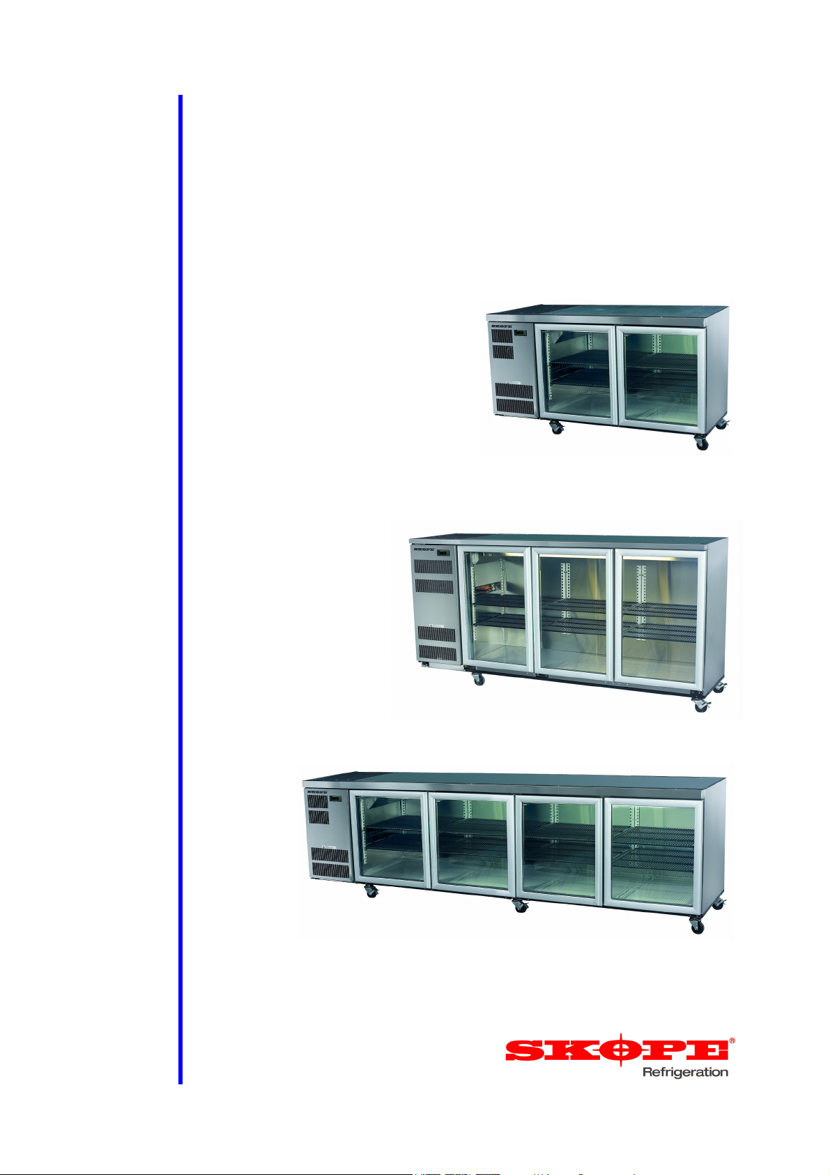
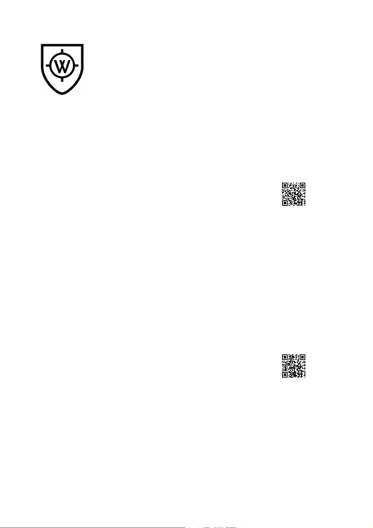
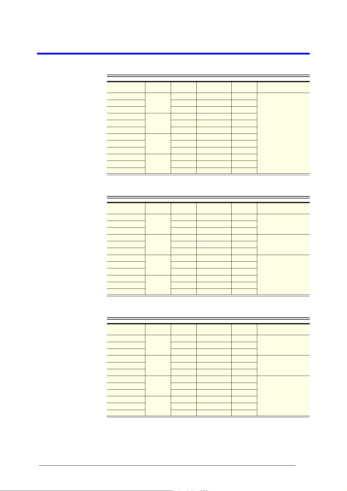
SKOPE Backbar, Counterline & Slimline
BB, CL & CC Series
1, 2 & 3 Door Horizontal Chillers
CL400
User Manual
MAN11015 Rev. 2.1 Mar. 2019
BB580
CL800
Page 2
SKOPE Warranty Protection
Register now for peace of mind
It’s quick and simple. Take a few minutes to register
your SKOPE product and enjoy more efficient
support plus other warranty benefits. When
registering, make sure you have your cabinet serial
number at hand.
To register online:
Visit our website at www.skope.com/warrantyprotection
then complete and submit the online registration form.
Or freephone:
1800 121 535 (Australia)
0800 947 5673 (New Zealand)
SKOPE 1-year Extended Warranty
Extend your Warranty Protection by 1 year during registration. Please
check you have not already organised an extended warranty through
your dealer at time of purchase. For pricing information on an extended
warranty visit www.skope.com/warrantyprotection
Service & Support
We know you will get years of satisfaction from your new SKOPE
product when you follow a few simple preventative maintenance
guidelines.
Helpful information is available on our website
www.skope.com/serviceandsupport
Thank you for purchasing a SKOPE refrigeration product.
Page 3

CONTENTS
1 Models
Backbar . . . . . . . . . . . . . . . . . . . . . . . . . . . . . . . . . . . . . . . . . . . . . . . .4
Counterline . . . . . . . . . . . . . . . . . . . . . . . . . . . . . . . . . . . . . . . . . . . . . 4
Slimline . . . . . . . . . . . . . . . . . . . . . . . . . . . . . . . . . . . . . . . . . . . . . . . . 4
2 Installation
Safety First . . . . . . . . . . . . . . . . . . . . . . . . . . . . . . . . . . . . . . . . . . . 5
Locating the Cabinet . . . . . . . . . . . . . . . . . . . . . . . . . . . . . . . . . . . . . .6
Location . . . . . . . . . . . . . . . . . . . . . . . . . . . . . . . . . . . . . . . . . . . . . 6
Ventilation . . . . . . . . . . . . . . . . . . . . . . . . . . . . . . . . . . . . . . . . . . . 6
Power Supply . . . . . . . . . . . . . . . . . . . . . . . . . . . . . . . . . . . . . . . . . 6
Positioning the Cabinet . . . . . . . . . . . . . . . . . . . . . . . . . . . . . . . . . . . .7
Legs and Castors . . . . . . . . . . . . . . . . . . . . . . . . . . . . . . . . . . . . . 7
Shelving. . . . . . . . . . . . . . . . . . . . . . . . . . . . . . . . . . . . . . . . . . . . . . . .8
Fitting the Shelves . . . . . . . . . . . . . . . . . . . . . . . . . . . . . . . . . . . . .8
Loading Product . . . . . . . . . . . . . . . . . . . . . . . . . . . . . . . . . . . . . . . 8
Remote Cabinet Installation . . . . . . . . . . . . . . . . . . . . . . . . . . . . . . . . 9
Electronic Controller . . . . . . . . . . . . . . . . . . . . . . . . . . . . . . . . . . . . 9
Pipe Locations . . . . . . . . . . . . . . . . . . . . . . . . . . . . . . . . . . . . . . . .9
3 Operation
Automatic Start-Up . . . . . . . . . . . . . . . . . . . . . . . . . . . . . . . . . . . . . .10
Refrigeration Unit . . . . . . . . . . . . . . . . . . . . . . . . . . . . . . . . . . . . .10
Cabinet Lighting . . . . . . . . . . . . . . . . . . . . . . . . . . . . . . . . . . . . . .10
Electronic Controller . . . . . . . . . . . . . . . . . . . . . . . . . . . . . . . . . . . 10
Electronic Controller . . . . . . . . . . . . . . . . . . . . . . . . . . . . . . . . . . . . . 11
Controller Overview . . . . . . . . . . . . . . . . . . . . . . . . . . . . . . . . . . .12
Temperature Setpoint . . . . . . . . . . . . . . . . . . . . . . . . . . . . . . . . .12
Controller Alarms . . . . . . . . . . . . . . . . . . . . . . . . . . . . . . . . . . . . . 13
4 Servicing
Cleaning . . . . . . . . . . . . . . . . . . . . . . . . . . . . . . . . . . . . . . . . . . . . . . 14
Cabinet . . . . . . . . . . . . . . . . . . . . . . . . . . . . . . . . . . . . . . . . . . . . . 14
Condenser Coil . . . . . . . . . . . . . . . . . . . . . . . . . . . . . . . . . . . . . . 14
Lighting . . . . . . . . . . . . . . . . . . . . . . . . . . . . . . . . . . . . . . . . . . . . . . . 15
Cabinet Interior Lights . . . . . . . . . . . . . . . . . . . . . . . . . . . . . . . . .15
Troubleshooting. . . . . . . . . . . . . . . . . . . . . . . . . . . . . . . . . . . . . . . . . 16
Page 4
1 Models
Backbar
Model Config. Doors
BB380i-2SL
BB580i-3SL 3 Integral 3.9A
BB780i-4SL 4 Integral 4.0A
BB380i-2SW
BB580i-2SW 3 Integral 3.6A
BB780i-4SW 4 Integral 3.8A
BB380r-2SL
BB580r-3SL 3 Remote 1.5A
BB780r-4SL 4 Remote 1.6A
BB380r-2SW
BB580r-3SW 3 Remote 0.9A
BB780r-4SW 4 Remote 1.4A
Sliding
doors
Swing
doors
Sliding
doors
Swing
doors
2 Integral 3.6A
2 Integral 3.4A
2 Remote 0.9A
2 Remote 0.7A
Refrigeration
unit
Current
draw
Counterline
Model Config. Doors
CL400i-2SL
CL600i-3SL 3 Integral 3.4A
CL800i-4SL 4 Integral 4.0A
CL400i-2SW
CL600i-3SW 3 Integral 3.2A
CL800i-4SW 4 Integral 3.8A
CL400r-2SL
CL600r-3SL 3 Remote 0.9A
CL800r-4SL 4 Remote 1.3A
CL400r-2SW
CL600r-3SW 3 Remote 0.7A
CL800r-4SW 4 Remote 1.0A
Sliding
doors
Swing
doors
Sliding
doors
Swing
doors
2 Integral 2.5A
2 Integral 2.3A
2 Remote 0.5A
2 Remote 0.3A
Refrigeration
unit
Current
draw
Operating temperature
range
+1°C to +4°C up to 32°C
ambient
Operating temperature
range
+1°C to +4°C up to 32°C
ambient
+1°C to +4°C up to 40°C
ambient
+1°C to +4°C up to 32°C
ambient
Slimline
Model Config. Doors
CC300i-2SL
CC500i-3SL 3 Integral 3.4A
CC700i-4SL 4 Integral 4.0A
CC300i-2SW
CC500i-3SW 3 Integral 3.2A
CC700i-4SW 4 Integral 3.8A
CC300r-2SL
CC500r-3SL 3 Remote 0.9A
CC700r-4SL 4 Remote 1.3A
CC300r-2SW
CC500r-3SW 3 Remote 0.7A
CC700r-4SW 4 Remote 1.0A
SKOPE Backbar, Counterline & Slimline
User Manual
Sliding
doors
Swing
doors
Sliding
doors
Swing
doors
Refrigeration
unit
2 Integral 2.5A
2 Integral 2.3A
2 Remote 0.5A
2 Remote 0.3A
Current
draw
Operating temperature
range
+1°C to +4°C up to 32°C
ambient
+1°C to +4°C up to 40°C
ambient
+1°C to +4°C up to 32°C
ambient
4
Page 5
SKOPE Backbar, Counterline & Slimline
2 Installation
Safety First Always observe safety precautions when using any electrical appliance.
Read these instructions carefully and retain them for future reference.
When the appliance is used by or near young children or infirm persons,
close supervision is necessary, especially to ensure children do not play
with it.
Do not use this appliance for other than its intended use.
Do not cover the grilles or block the entry or exhaust of airflow by
placing objects up against the refrigeration unit.
Do not probe any opening.
Only use this appliance with the voltage specified on the rating label.
Ensure the appliance has adequate ventilation as this is essential to
economical, high performance.
Be careful not to touch moving parts and hot surfaces.
For your own safety and that of others, ensure that all electrical work is
done by authorised personnel.
If the power supply flexible cord becomes damaged, it must be replaced
by an authorised service agent or similarly qualified person in order to
avoid a hazard.
Ensure all necessary safety precautions are observed during installation
or removal of the refrigeration unit.
The appliance is not designed to be stable while in motion. Use extreme
caution when moving or transporting it.
Do not store explosive substances such as aerosol cans with a
flammable propellant in this appliance.
Please contact SKOPE customer services for advice regarding disposal
of this appliance.
CAUTION
Never overload the power supply, which could damage the
chiller and product. See the rating label inside the cabinet for
the safe power supply and current draw.
WARNING
Always disconnect the chiller from the mains power supply
before cleaning or maintenance.
WARNING
If retrofitting door locks, ensure retrofit is done by a SKOPE
approved service technician following SKOPE guidelines on
instruction sheet PRN8503.
Installation
User Manual
5
Page 6
SKOPE Backbar, Counterline & Slimline
Locating the Cabinet
Location When positioning the cabinet, avoid direct sunlight and warm draughts etc.
The cabinet must NOT be situated where it is affected by warm or hot air
from adjacent equipment, as this will compromise the airflow and
performance of the chiller.
The cabinet must be positioned on a level surface for the doors to shut and
seal correctly, and to prevent the condensate tray from overflowing.
Adequate allowance should be made for door opening.
Always ensure that the top of the cabinet is shielded from impact and
moisture, with either a SKOPE provided bench top, or with a custom or
existing bench top.
When installing the cabinet
Avoid direct sunlight and warm draughts etc.
Allow adequate space for the doors to open fully.
Ensure the cabinet is positioned on a level surface so the doors shut
and seal correctly and to prevent the condensate tray from overflowing.
Ventilation For efficient operation of the chiller, it is essential that adequate ventilation
be provided around the front of the refrigeration unit. Normal operating
conditions should not exceed the operating temperature range (see page 4).
It is critical that the hot refrigeration exhaust air is not restricted and that it
can easily flow out and away from the front of the cabinet. Never store
cardboard cartons or other items in front of the refrigeration unit. The
ventilation slots on the unit front cover must be kept clear at all times.
Power Supply The chiller is supplied with a flexible power cord and plug, which is located
at the rear of the cabinet.
Before final positioning of the cabinet, pull the power cord out from the
cabinet and connect to the power supply.
WARNING:
Do NOT overload the power supply. See the rating label inside
the cabinet for power supply and current draw.
6
Installation
User Manual
Page 7

SKOPE Backbar, Counterline & Slimline
Castor
mounting plate
Adjustable leg
Plastic foot
Lock nut
Positioning the Cabinet
Legs and
Castors
The chiller is packed with a set of adjustable height legs and a set of
adjustable height castors. Either of these sets can be fitted to the cabinet
depending on specific height and manoeuvrability requirements. The legs or
castors should be fitted to the base of the cabinet before final positioning.
The adjustable legs screw into the castor mounting plates attached to the
bottom of the cabinet. The adjustable legs can adjust the cabinet height up
to 30mm.
To adjust leg height
1. Turn the black plastic foot
at the bottom of the leg
counter-clockwise to raise
the height or clockwise to
lower.
The adjustable castors screw into the castor mounting plates attached to the
bottom of the cabinet. The two lockable castors should be fitted to the front
of the cabinet and the non-locking castors fitted to the rear. The adjustable
castors can adjust the cabinet height up to 15mm.
To adjust castor height
1. Loosen the lock nut.
2. Turn the castor counterclockwise to raise the
height or clockwise to
lower (see image below).
Re-tighten each lock nut
after final adjustment has
been made.
Installation
User Manual
7
Page 8

SKOPE Backbar, Counterline & Slimline
Shelving
Fitting the
Shelves
Loading Product
Remove all packaging material from the shelves. Clip the shelf support
brackets into the shelf support strips, at the desired heights, and fit the
shelves. The shelves may be positioned at different heights to suit various
products. Always ensure that the shelf clips are securely engaged in each
of the shelf support strips. The shelf support strips are marked ‘+’ for easy
location of shelf clips and can be lifted up and removed for cleaning
purposes.
The chiller should be left running for 30 minutes before loading with product.
When loading product
Allow air space around all the product to ensure even cooling and
efficient operation of the chiller.
Do not allow products to overhang the front of the shelf as this could
prevent the doors from shutting. Leave an airspace of at least 75mm
above product loaded on the top shelf.
Do not exceed a maximum loading of 20kg per shelf.
Remove some product if the shelves are flexing or bending.
8
Installation
User Manual
Page 9

SKOPE Backbar, Counterline & Slimline
Unit Pipework Cover
Refrigeration Unit Compartment
Drain Tube
Suction Line
Liquid Line
Rear of Cabinet
Remote Cabinet Installation
SKOPE horizontal remote cabinets are supplied with a seperate instruction
sheet: Guidelines for SKOPE remote Refrigeration (PRN2362), and
specification sheet: SKOPE Gen 2 Horizontal Remote Cooler -
Specifications (PRN1647). Refer to these sheets for SKOPE remote
refrigeration installation guidelines and specifications.
Electronic Controller
When the cabinet is connected to the power supply, the electronic controller
will display the current cabinet temperature. On the controller display, the
symbol will indicate the compressor output signal has been initiated and the
symbol will indicate the evaporator fan is on.
Pipe Locations Refer to the images below (remote chiller unit pictured) for component
locations and unit access points.
Installation
User Manual
9
Page 10

SKOPE Backbar, Counterline & Slimline
3 Operation
Automatic Start-Up
Connect the cabinet to the mains power supply and check operation of the
refrigeration unit and electronic controller. If the cabinet has been on its
back, leave for 30 minutes before running.
If the cabinet has been on its back, leave for 30 minutes
IMPORTANT
before running.
Refrigeration
Unit
Cabinet
Lighting
Electronic Controller
The compressor, and the condenser and evaporator fans should all operate
within two minutes from the time the cabinet is plugged in. This may be
verified by listening for compressor switch-on and checking for air
movement out of the top ventilation slots in the refrigeration unit front cover.
The compressor and condenser fan should switch on and off depending on
the cabinet temperature.
The light switch, located next to the electronic controller on the refrigeration
unit front cover, activates the cabinet interior lighting and can be switched on
or off as required.
When the cabinet is connected to the power supply, the electronic controller
will display the current cabinet temperature. The compressor LED will
indicate the compressor is operating and the evaporator fan LED will
normally come on within two minutes (see “Electronic Controller” on page 11
for controller display).
To ensure efficient operation, the electronic controller forces regular
defrosts. During the defrost cycle, the compressor and condenser fan switch
off and the evaporator fan stays on.
10
Operation
User Manual
Page 11

Electronic Controller
910
11
12
43
15
14
1312
8
7
6
5
Item Icon Function
Mute / program: Mutes the audible alarm (buzzer) and
1
deactivates the alarm relay. To initiate program sets, press for 5
seconds.
SKOPE Backbar, Counterline & Slimline
2 Up: To scroll settings up (in program mode).
3
4
5
6 Fan: Shows when the fan is operational.
7
8 Aux: n.a.
9 Alarm: Flashes in the event of alarms.
10 Clock: n.a.
11 Light: n.a.
12 Service: Flashes in the event of malfunctions.
Set point: If pressed for more than 2 seconds displays and / or
enables changing the temperature setpoint.
Manual defrost / down: Press for more than 5 seconds to initiate
manual defrost. To scroll settings down (in program mode).
Compressor: ON when the compressor and condenser fan
starts. Flashes when activation of the compressor is temporarily
delayed.
Defrost: ON when the defrost is activated. Flashes when the
activation of the defrost is temporarily delayed due to procedures
in progress.
13
14
15
DISPLAY: Shows the cabinet temperature. Flashes when the
door is open.
HACCP: n.a.
CONTINUOUS CYCLE: On when freezer is running in continuous
run mode.
Operation
User Manual
11
Page 12

SKOPE Backbar, Counterline & Slimline
Controller
Overview
Temperature
Setpoint
The CAREL ir33 electronic controller controls and displays the internal
cabinet temperature. The preset temperature setting keeps the product
temperature within the operating temperature range (see page 4). The
electronic controller also signals temperature alarms (see next page).
For general operation, the electronic controller requires no initial setup or
additional programming.
When the cabinet is connected to the power supply, the electronic controller
will display the current cabinet temperature. The compressor LED will
indicate the compressor is operating and the evaporator fan LED will
normally come on within 2 minutes.
The chiller temperature setpoint is factory set (see table below) and can be
adjusted if necessary. SKOPE do not recommend that the setpoint be
changed unless it is absolutely necessary, and then only by small
increments at a time.
Factory setpoints
Model series Factory setpoint
Backbar 1.5°C
Counterline & Slimline
1.0°C
To view and adjust the temperature setpoint
1. To view the setpoint:
Press and hold the key for 2 seconds, until the
setpoint value flashes.
2. To adjust the setpoint:
Press either the or keys to display the required
setpoint value.
3. Press the key again to memorise the new setpoint
value. If this is not done within 60 seconds changes will
be lost and you will need to repeat the above
procedure.
12
Operation
User Manual
Page 13

SKOPE Backbar, Counterline & Slimline
Controller
Alarms
The following table explains messages that the electronic controller displays
and related alarms. Alarms signal unexpected operational changes in the
freezer and stop when action is taken to resolve the problem.
Code Display Alarm Action
1. Check the cabinet product loading to ensure
ventilation slots are not blocked, and that
product does not overhang the shelves.
Ensure the doors are closed.
2. Ensure the cabinet is installed with good
refrigeration unit ventilation.
3. Check and clean the condenser coil (see
page 14).
4. If immediate alarm recovery is required unplug the cabinet from the power supply for
1 minute, then reconnect to power supply. If
alarm persists, contact SKOPE.
NOTE: The ‘HI’ and ‘LO’ alarms deactivate the
cabinet lighting and trim heaters.
1. Clean the condenser coil (see page 14).
2. Check refrigeration ventilation. Ensure clear
airpath in front of the cabinet.
3. Ensure the cabinet is installed in a suitable
environment.
4. To reset the ‘CHt’ alarm - unplug the cabinet
from the power supply for 1 minute, then
reconnect to power supply. If alarm persists,
contact SKOPE.
Flashing
Flashing
Flashing
Flashing
Product HIGH
temperature alarm
(auto reset)
Product LOW
temperature alarm
(auto reset)
Refrigeration
system high
temperature
pre-warning (auto
reset)
Refrigeration
system and
cabinet high
temperature
shutdown (manual
reset)
Flashing
Flashing
Flashing
None
Flashing
Flashing
Flashing
None
None
Control probe fault
Evaporator probe
fault
Condenser probe
fault
Defrost over-time
limit
Real-time clock
fault
Controller E prom
error
Controller E prom
error
Start defrost
request
End defrost
request
To reset alarm - unplug the cabinet from the
power supply for 1 minute, then reconnect to
power supply.
1. If alarm persists, contact SKOPE.
None
Operation
User Manual
Flashing
Door open alarm
Check that a door or drawer has not been left
open. Note: The audible alarm buzzer cannot
be turned off manually.
13
Page 14

SKOPE Backbar, Counterline & Slimline
Condenser coil
4 Servicing
Cleaning
Cabinet When necessary, wipe both the interior and exterior of the cabinet with a
damp cloth. Ensure the cabinet is disconnected from the mains power
supply before cleaning the cabinet.
Disconnect the cabinet from the mains power supply before
cleaning the condenser coil or washing the cabinet with water.
CAUTION
Condenser
Coil
Integral cabinets only. The condenser coil should be brushed clean once a
month and blown clean by qualified service personnel every six months.
Over time, dust may accumulate within the condenser that cannot be
removed with a brush. If this occurs, contact SKOPE to arrange for a
SKOPE authorised service agent to clean the condenser with compressed
air. The condenser coil is located inside the refrigeration unit compartment
and is accessed by opening the unit front cover. Disconnect the cabinet from
the power supply before cleaning the condenser coil.
14
IMPORTANT
If the electronic controller display flashes ‘cht’ the condenser
coil must be cleaned immediately.
Servicing
User Manual
Page 15

Lighting
SKOPE Backbar, Counterline & Slimline
Cabinet
Interior Lights
The cabinet is fitted with cabinet interior light/s mounted above the doors on
the ceiling of the cabinet. Backbar pass-through cabinets are fitted with
lights above the front and back doors. Refer to the table below for light tube
specifications.
Interior light specifications
Type LED Tube Specification
Two door cabinet 20 Watt T8 Frosted LED tube (Ø26 x 900mm, 5500K)
Three door cabinet 24 Watt T8 Frosted LED tube (Ø26 x 1500mm, 5500K)
Four door cabinet Counterline & Slimline
Four door cabinet Backbar
20 Watt T8 Frosted LED tube (×2) (Ø26 x 900mm, 5500K)
24 Watt T8 Frosted LED tube (Ø26 x 1500mm, 5500K)
To replace the interior LED light tube
1. Disconnect the cabinet from the power supply (see page 14).
2. Remove the top light
diffuser by squeezing it
until it is released from the
housing.
3. Rotate the LED tube until
the pins on the ends of the
tube align with the slots,
then slide it out.
4. Fit a new LED tube and
clip the diffuser back into
place. When fitting
vertically mounted LED
tubes, ensure the tube is
fitted with the ‘Power’ end
at the top.
Servicing
User Manual
15
Page 16

SKOPE Backbar, Counterline & Slimline
Troubleshooting
Complaint Possible Cause Repair
1. Cabinet not
operating and
no controller
display:
2. Power
consumption
is higher than
expected:
3. Product is too
warm and
spoiling:
4. Warm cabinet
temperatures
and/or
compressor
operating for
long periods
(more than 1
hour):
• Loss of power supply. • Check mains power supply.
• Unit operating too hot. • Clean condenser (see
• Cabinet doors are opened
excessively.
• Restricted cabinet airflow. • Ensure product is not
• Temperature setpoint is too
warm.
• Blocked condenser. • Clean condenser (see
• Poor refrigeration unit
ventilation.
page 14).
• Ensure the chiller is installed
with good ventilation around
the refrigeration unit.
• Keep door/s open for
minimum time.
blocking airflow slots.
• Adjust setpoint (see
page 12).
page 14).
• Ensure the cabinet is
installed with good
ventilation around the
refrigeration unit.
16
Servicing
User Manual
Page 17

SKOPE Industries Limited
NEW ZEALAND CONTACT
Head Office
PO Box 1091, Christchurch
New Zealand
Freephone: 0800 947 5673
Fax: (03) 983 3896
E-mail: enquiry@skope.co.nz
Website: www.skope.co.nz
AUSTRALIAN CONTACT
A.B.N. 73 374 418 306
PO Box 7543, Baulkham Hills B.C.
NSW 2153, Australia
Freephone: 1800 121 535
Fax: 1800 121 533
E-mail: enquiry@skope.com.au
Website: www.skope.com.au
SKOPE Contacts
Trademark Infringement
The SKOPE trademark on this product is infringed if the owner, for the time being, does
any of the following:
• Applies the trade mark to the product after their state, condition, get-up or packaging
has been altered in any manner
• Alters, removes (including part removal) or obliterates (including part obliteration) the
trade mark on the product
• Applies any other trade mark to the product
• Adds to the product any written material that is likely to damage the reputation of the
trade mark
Notice of the above contractual obligations passes to:
• Successors or assignees of the buyer
• Future owners of the product
SKOPE Backbar, Counterline & Slimline
BB, CL & CC Series
User Manual
MAN11015
Rev. 2.1 Mar. 2019
© 2013 SKOPE Industries Limited. All rights reserved.
SKOPE Industries Limited reserve the right to alter specifications without notice.
is a registered trademark of SKOPE Industries Limited.
Loading...