

Page 1
B600-2/B600G-2
User Manual
MAN10530 Rev. 2.4 Mar. 2014
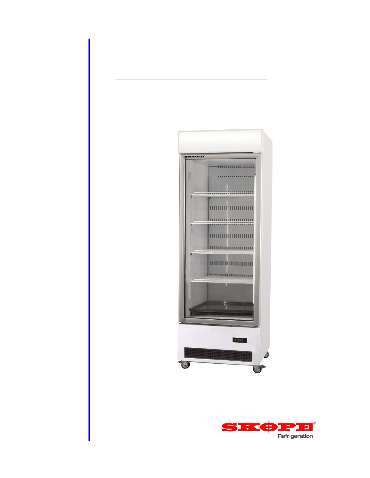
B600G-2
SKOPE Single Door Vertical Chiller
B600-2 (no sign) G60EV/X5990
B600G-2 (lit sign) G60EV
Page 2
SKOPE Warranty Protection
To activate your Warranty Protection, you must
register your product with SKOPE within 4 weeks
from date of invoice.
To register online:
Visit our website at www.skope.com/warrantyprotection
then complete and submit the online registration form.
Or alternatively contact our Customer Services team to register:
1800 121 535 (Australia)
0800 947 5673 (New Zealand)
SKOPE 1-year Extended Warranty
Extend your Warranty Protection by 1 year during registration. Please
check you have not already organised an extended warranty through
your dealer at time of purchase. For pricing information on an extended
warranty visit www.skope.com/warrantyprotection
Service & Support
We know you will get years of satisfaction from your new SKOPE
product when you follow a few simple preventative maintenance
guidelines.
Helpful information is available on our website
www.skope.com/serviceandsupport
Thank you for purchasing a SKOPE refrigeration product.
Page 3

SKOPE B600-2/B600G-2
User Manual
iii
CONTENTS
1 Installation
Safety First . . . . . . . . . . . . . . . . . . . . . . . . . . . . . . . . . . . . . . . . . . .4
Positioning the Cabinet . . . . . . . . . . . . . . . . . . . . . . . . . . . . . . . . . . . .5
Chiller Location . . . . . . . . . . . . . . . . . . . . . . . . . . . . . . . . . . . . . . . . 5
Ventilation . . . . . . . . . . . . . . . . . . . . . . . . . . . . . . . . . . . . . . . . . . . . 5
Before Operating. . . . . . . . . . . . . . . . . . . . . . . . . . . . . . . . . . . . . . . 5
Power Cord . . . . . . . . . . . . . . . . . . . . . . . . . . . . . . . . . . . . . . . . . . 5
Shelves . . . . . . . . . . . . . . . . . . . . . . . . . . . . . . . . . . . . . . . . . . . . . . . . 6
Bottom Shelf . . . . . . . . . . . . . . . . . . . . . . . . . . . . . . . . . . . . . . . . . .6
Wire Shelves . . . . . . . . . . . . . . . . . . . . . . . . . . . . . . . . . . . . . . . . .6
2 Operation
Automatic Start-Up . . . . . . . . . . . . . . . . . . . . . . . . . . . . . . . . . . . . . . . 7
Loading Product . . . . . . . . . . . . . . . . . . . . . . . . . . . . . . . . . . . . . . . . .7
EMS Controller Operations . . . . . . . . . . . . . . . . . . . . . . . . . . . . . . . . .8
Introduction . . . . . . . . . . . . . . . . . . . . . . . . . . . . . . . . . . . . . . . . . . 8
Self-Learning . . . . . . . . . . . . . . . . . . . . . . . . . . . . . . . . . . . . . . . . .8
Motion Sensor & Door Switch . . . . . . . . . . . . . . . . . . . . . . . . . . . . 8
Faceplate . . . . . . . . . . . . . . . . . . . . . . . . . . . . . . . . . . . . . . . . . . . . 9
Temperature Setpoint . . . . . . . . . . . . . . . . . . . . . . . . . . . . . . . . .10
Perishable Mode . . . . . . . . . . . . . . . . . . . . . . . . . . . . . . . . . . . . . 10
Messages and Alarms . . . . . . . . . . . . . . . . . . . . . . . . . . . . . . . . . 11
3 Servicing
Isolating Electrics . . . . . . . . . . . . . . . . . . . . . . . . . . . . . . . . . . . . . . .12
Cleaning . . . . . . . . . . . . . . . . . . . . . . . . . . . . . . . . . . . . . . . . . . . . . .12
Cabinet . . . . . . . . . . . . . . . . . . . . . . . . . . . . . . . . . . . . . . . . . . . . . 12
Condenser Coil . . . . . . . . . . . . . . . . . . . . . . . . . . . . . . . . . . . . . . 12
Lighting . . . . . . . . . . . . . . . . . . . . . . . . . . . . . . . . . . . . . . . . . . . . . . .13
Interior Light . . . . . . . . . . . . . . . . . . . . . . . . . . . . . . . . . . . . . . . . .13
Sign Light . . . . . . . . . . . . . . . . . . . . . . . . . . . . . . . . . . . . . . . . . . . 14
Troubleshooting. . . . . . . . . . . . . . . . . . . . . . . . . . . . . . . . . . . . . . . . . 15
Page 4
4
Installation
User Manual
SKOPE B600-2/B600G-2
1 Installation
Safety First Always observe safety precautions when using any electrical appliance.
Read these instructions carefully and retain them for future reference.
When the appliance is used by or near young children or infirm persons,
close supervision is necessary, especially to ensure children do not play
with it.
Do not use this appliance for other than its intended use.
Do not cover the grilles or block the entry or exhaust of airflow by
placing objects up against the refrigeration cassette.
Do not probe any opening.
Do not store explosive substances such as aerosol cans with a
flammable propellant in this appliance.
Only use this appliance with the voltage specified on the cabinet rating
label affixed to the refrigeration cassette.
Ensure the chiller has adequate ventilation as this is essential to
economical, high performance.
Be careful not to touch moving parts and hot surfaces.
For your own safety and that of others, ensure that all electrical work is
done by authorised personnel.
If the power supply flexible cord becomes damaged, it must be replaced
by an authorised service agent or similarly qualified person in order to
avoid a hazard.
Ensure all necessary safety precautions are observed during installation
or removal of the refrigeration cassette.
This appliance is not designed to be stable while in motion. Use
extreme caution when moving or transporting the appliance.
This appliance is not intended for use with perishable product, which are
high risk foods likely to support the growth of harmful bacteria.
Perishable product requires continuously cold temperatures.
WARNING
Always isolate the chiller from the mains power supply before
attempting any maintenance.
CAUTION
Never overload the power supply, which could damage the
chiller and product. See the rating label inside the cabinet for
the safe power supply and current draw.
Page 5

5
SKOPE B600-2/B600G-2
Installation
User Manual
Positioning the Cabinet
Chiller
Location
The location of the chiller may be the single most important decision that will
extend its life and ensure economical, high performance. We recommend
that you put the chiller in the coolest place possible because it will use less
power and last longer.
Allow adequate space for doors to open and close properly. Self-closing
doors have internal torsion bars pretensioned at the factory, and must be
unobstructed. Ensure the cabinet sits on a level surface so that the doors
shut and correctly seal. Level footing also prevents the condensate tray from
overflowing.
Ventilation Ensure there is always at least a 50mm gap around the back, top and
underside of the cabinet. Keep the ventilation slots in the front panel clear at
all times, never store cardboard cartons or other objects in front of the
chiller.
Before
Operating
Ensure both rear spacers are rotated outwards and fully tightened. This will
provide the necessary air gap at the rear of the cabinet for correct operation.
Power Cord The chiller has a flexible power cord fitted with a 3-pin plug, which exits the
rear of the cabinet at floor level. Pull the power cord around so that it’s not
trapped before you position the cabinet.
CAUTION
To prevent over heating and conserve energy, ensure air flows
freely all around the chiller - including front, back, top and
underside (minimum 50mm gap).
Back of Chiller
Power Cord
Rear Spacer
Page 6

6
Installation
User Manual
SKOPE B600-2/B600G-2
Shelves
The chiller is supplied with four wire shelves and one solid bottom stainless
steel shelf.
Bottom Shelf The solid bottom shelf is fixed into place on the floor of the chiller. It is
important that this shelf is always in place as it directs the interior air
circulation.
Wire Shelves The wire shelves may be fitted at different heights to suit various products.
Each shelf is held in place with four shelf clips, which engage in the shelf
support strips. The support strips are numbered for easy location of shelf
clips.
To fit the wire shelves
IMPORTANT
For correct chiller operation, the solid bottom shelf must
always be in the bottom of the chiller.
1. Unpack the shelves and shelf clips from inside the cabinet.
2. Establish the desired position for the shelves and securely engage a shelf
clip in each of the shelf support strips.
3. Sit the shelves onto the
shelf support strips.
Page 7
7
SKOPE B600-2/B600G-2
Operation
User Manual
2 Operation
Automatic Start-Up
After the cabinet has been positioned in a suitable place, plug it in and check
the following activity.
After initial start-up, the EMS electronic controller starts its self-learning
process, and the cabinet will operate without any assistance. Refer to “SelfLearning” on page 8 for more information.
Loading Product
Let the chiller run 30 minutes before loading it with product the first time.
When loading the chiller:
Allow adequate air space around each item to ensure even cooling and
efficient operation of the chiller.
Do not exceed a maximum load of 20kg per shelf.
Remove some product if the shelves are flexing.
Do not let anything overhang the shelves because this might stop the
doors from shutting or even break something.
Item Activity
Condenser Fan The condenser fan starts when the chiller is plugged in.
Lighting
The lights that illuminate the cabinet interior and top sign
(top sign fitted to B600G-2 only) will come on when the
chiller is turned on.
Electronic
Controller
An electronic controller runs the chiller and is visible
behind the front panel. The display panel first flashes startup messages before stabilising on the cabinet
temperature.
Compressor
The compressor starts about three minutes after the lights
go on. To verify, listen for the compressor and check that
the COMPRESSOR light is green on the EMS Advanced
controller. The compressor turns off when the product
temperature reaches around +2°C and turns on again
when it reaches about +4°C.
Evaporator Fan
The evaporator fan starts about 30 seconds after the
compressor. To verify, check that the FAN light is green on
the EMS controller.
Page 8
8
Operation
User Manual
SKOPE B600-2/B600G-2
EMS Controller Operations
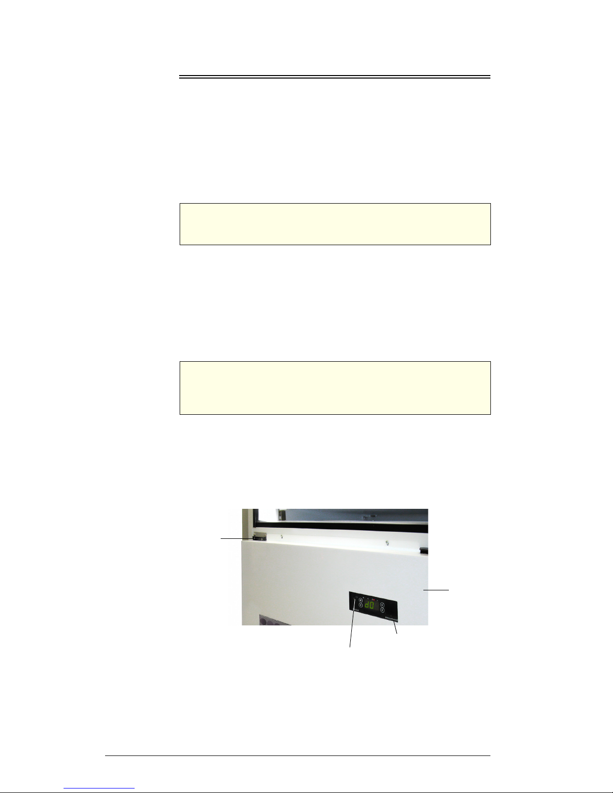
Introduction The Energy Management System (EMS) controller is located inside the
refrigeration unit compartment, with the faceplate visible behind the front
panel.
The EMS controller detects variable business hours and switches the chiller
to active mode approximately two hours prior to opening, and then changes
to stand-by mode at close of business. While in the economical stand-by
mode, the temperature inside the chiller is moderated and the cabinet lights
turn off.
Self-Learning After initial start-up, the EMS controller goes into learning mode for 24 hours
to establish the density of shopper traffic and the business’s opening/closing
pattern. It’s always gathering data about shopping activity and updating
itself. A service agent is not required if the store hours change, or you
disconnect the power to move the chiller.
The EMS controller continuously collects data from two sources:
motion sensor
door switch
Motion Sensor
& Door Switch
The motion sensor detects activity in front of the chiller and feeds data to the
EMS controller. The motion sensor is located on the faceplate of the EMS
controller, visible on the front panel.
The chiller is fitted with a door switch below the door. The door switch tells
the EMS controller how often the door is opened. A small magnet in the door
frame activates the switch.
CAUTION
The EMS controller must only be adjusted by an authorised
service agent.
IMPORTANT
Disconnecting the refrigeration unit from the power supply
does not reset the self-learning module. Only an authorised
service agent can adjust the program.
Motion Sensor
Door Switch
EMS Controller
Front Panel
Page 9
9
SKOPE B600-2/B600G-2
Operation
User Manual
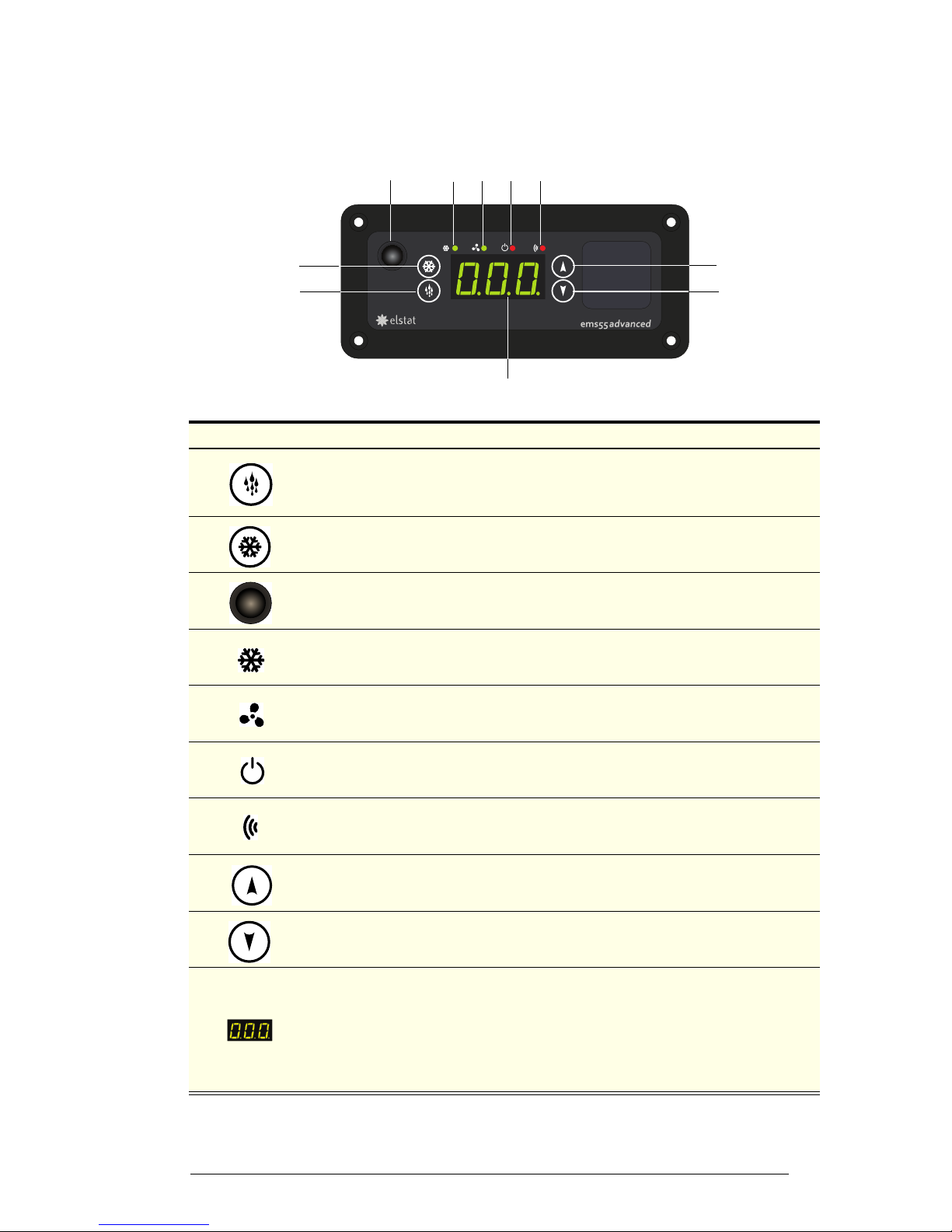
Faceplate Because the EMS controller plays such an important role, it’s helpful to know
the parts of the faceplate you will use.
No. Item Description
1
DEFROST button. Manually activates an additional defrost cycle, and used to program
the controller.
The first automatic defrost occurs six hours after the first off-cycle.
2 SET button. Used to program the controller.
3
Eye of the infrared motion sensor. It detects activity within five metres around the front
of the chiller, and feeds the data to the EMS controller.
4 LED for the compressor light – green when on.
5 LED for the evaporator fan – green when on.
6 LED indicating perishable mode – red when on. See page 10 for more information.
7
LED linked to the motion sensor and flashes red when there is activity around the
chiller, but otherwise off.
8 UP button. Used to program the controller.
9 DOWN button. Used to program the controller.
10
Digital display of cabinet temperature or messages (see next page for details).
The temperature is what the sensor inside the chiller detects, and not necessarily the
product temperature. However, they may be very close depending on how the
controller is set to sense temperature.
When the chiller is in stand-by mode, the controller displays three bars (- - -). This
should not be displayed during normal business hours.
8
9
1
2
3
4567
10
Page 10
10
Operation
User Manual
SKOPE B600-2/B600G-2
Temperature
Setpoint
The chiller temperature setpoint is factory set at 1°C. If necessary the
standard setting can be adjusted between 0°C and 4.0°C. SKOPE do not
recommend that the setpoint be changed unless it is absolutely necessary,
and then only by small increments at a time.
To adjust the setpoint
Perishable
Mode
The chiller has the ability to operate in either perishable mode or nonperishable mode. When in perishable mode the symbol on the EMS
controller faceplate is lit red, when in non-perishable mode the symbol is
not lit.
Perishable mode is for use with perishable products such as dairy or food
products. When in perishable mode the chiller temperature is kept
constantly cool at all times. During standby periods the lights switch off and
the fans cycle on and off. Perishable mode must be used when perishable
product is being stored inside the chiller.
Non-perishable mode is for use with non-perishable products such as
carbonated drinks and water. When in non-perishable mode, the chiller
temperature is moderated, the lights switch off and the fans cycle on and off
during standby periods resulting in maximum energy savings. Follow the
steps below to change between perishable and non-perishable mode.
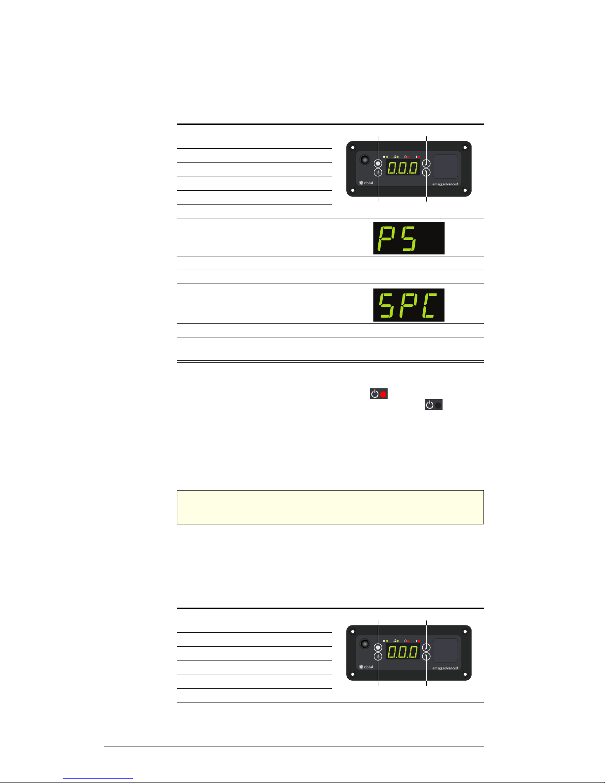
To change between perishable and non-perishable mode
1. Push and hold the set button, PAS
appears on the display.
2. Release the set button.
3. Push the set button four times.
4. Push the up button once.
5. Push the down button twice.
6. Push the defrost button twice.
7. Push the down button to nagivate
to the parameter menu. PS will
show on the display.
8. Push the set button to enter the parameter menu.
9. Push and hold the
set
button to scroll through the parameter menu.
10. Release the set button when
SPC
appears on the display.
11. Push the
up
and
down
button to change the value.
12. Once the desired mode setting is flashing on the display, leave the controller
for 20-30 seconds to save the setting.
Set
Defrost
Up
Down
IMPORTANT
Ensure perishable mode is used when perishable product is being
stored inside the chiller.
1. Push and hold the set button, PAS
appears on the display.
2. Release the set button.
3. Push the set button four times.
4. Push the up button once.
5. Push the down button twice.
6. Push the defrost button twice.
Continued over page
Set
Defrost
Up
Down
Page 11
11
SKOPE B600-2/B600G-2
Operation
User Manual
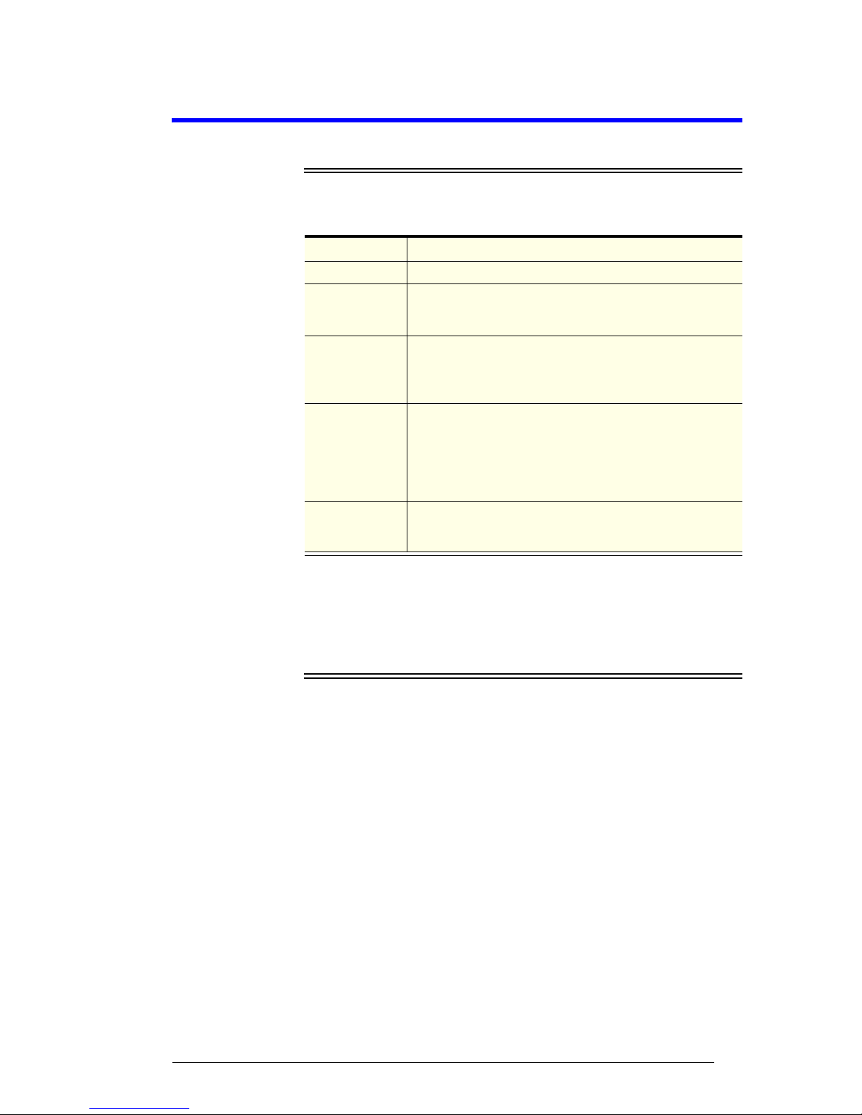
Messages and
Alarms
The following table explains messages that the EMS Advanced controller
displays and related alarms. Alarms signal unexpected operational changes
in the chiller and stop when you disconnect the chiller from the power supply
at the isolating switch.
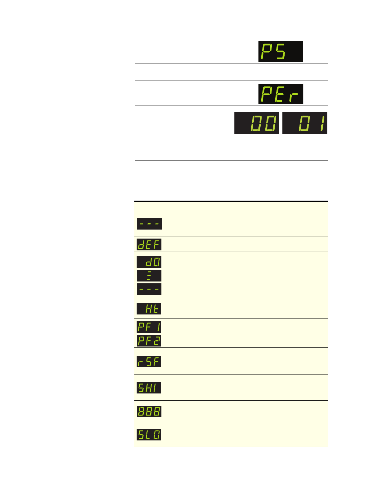
7. Push the down button to nagivate
to the parameter menu. PS will
show on the display.
8. Push the set button to enter the parameter menu.
9. Push and hold the
set
button to scroll through the parameter menu.
10. Release the set button when
PEr
appears on the display.
11. Push the
down
button to change
between perishable and nonperishable mode:
0 = Non-perishable mode
1 = Perishable mode
12. Once the desired mode setting is flashing on the display, leave the controller
for 20-30 seconds to save the setting.
Non-perishable mode
Perishable mode
Display Description
When the chiller is in stand-by mode, the EMS Advanced controller
displays three bars. This should not be displayed during normal
business hours. When the chiller becomes operational, the display
changes to the temperature.
Defrost cycle in progress.
Door Open. The EMS Advanced controller detects an open door
through a door switch in the door, and has found one open. If it stays
open over two minutes, an alarm sounds, but stops when the door
closes again.
If the door remains open five minutes, such as when loading product,
then the alarm stops and the EMS Advanced controller turns off the
compressor. The compressor starts again when the door closes.
High Temperature. The refrigeration system has overheated, and an
alarm sounds. The EMS Advanced controller turns off the system to
avoid damage. Contact a service agent.
Probe Failure. A temperature sensor in the cabinet or condenser has
failed, and an alarm sounds. Contact a service agent.
Refrigeration System Failure. There is a refrigeration system failure,
and the EMS Advanced controller turns it off to avoid damage. An
alarm sounds when the system does not reach the preset temperature
within 72 hours.
Contact a service agent.
Supply High. The voltage from the main supply is too high, and an
alarm sounds. The controller turns off the electrical motors,
continuously monitors the voltage level, and restores power as soon
as the voltage returns to a safe level.
Freeze up protection. The cabinet temperature is too low. The
compressor stops running and the evaporator fans run continuously
until the cabinet temperature reaches an acceptable level.
Supply Low. The voltage from the main supply is too low, and an
alarm sounds. The controller turns off the electrical motors,
continuously monitors the voltage level, and restores power as soon
as the voltage returns to an appropriate level.
Page 12
12
Servicing
User Manual
SKOPE B600-2/B600G-2
3 Servicing
Isolating Electrics
You should isolate the cabinet from the power supply before attempting any
maintenance. Use the isolating switch to turn off electrics to the cabinet and
refrigeration unit without unplugging the cabinet from the wall. The isolating
switch is located on the right hand side of the refrigeration unit compartment.
To isolate the power supply
Cleaning
Cabinet Periodically wipe the inside and outside of the cabinet with a damp cloth,
taking care to keep moisture away from electrical parts. As with any
maintenance, ensure the cabinet is isolated from the power supply before
cleaning.
Condenser
Coil
To ensure trouble-free performance, we strongly urge monthly cleaning with
a soft brush to remove dust and fluff. A more thorough cleaning is
recommended every six months, by qualified service personnel. The
condenser coil must be kept clean for efficient and reliable operation.
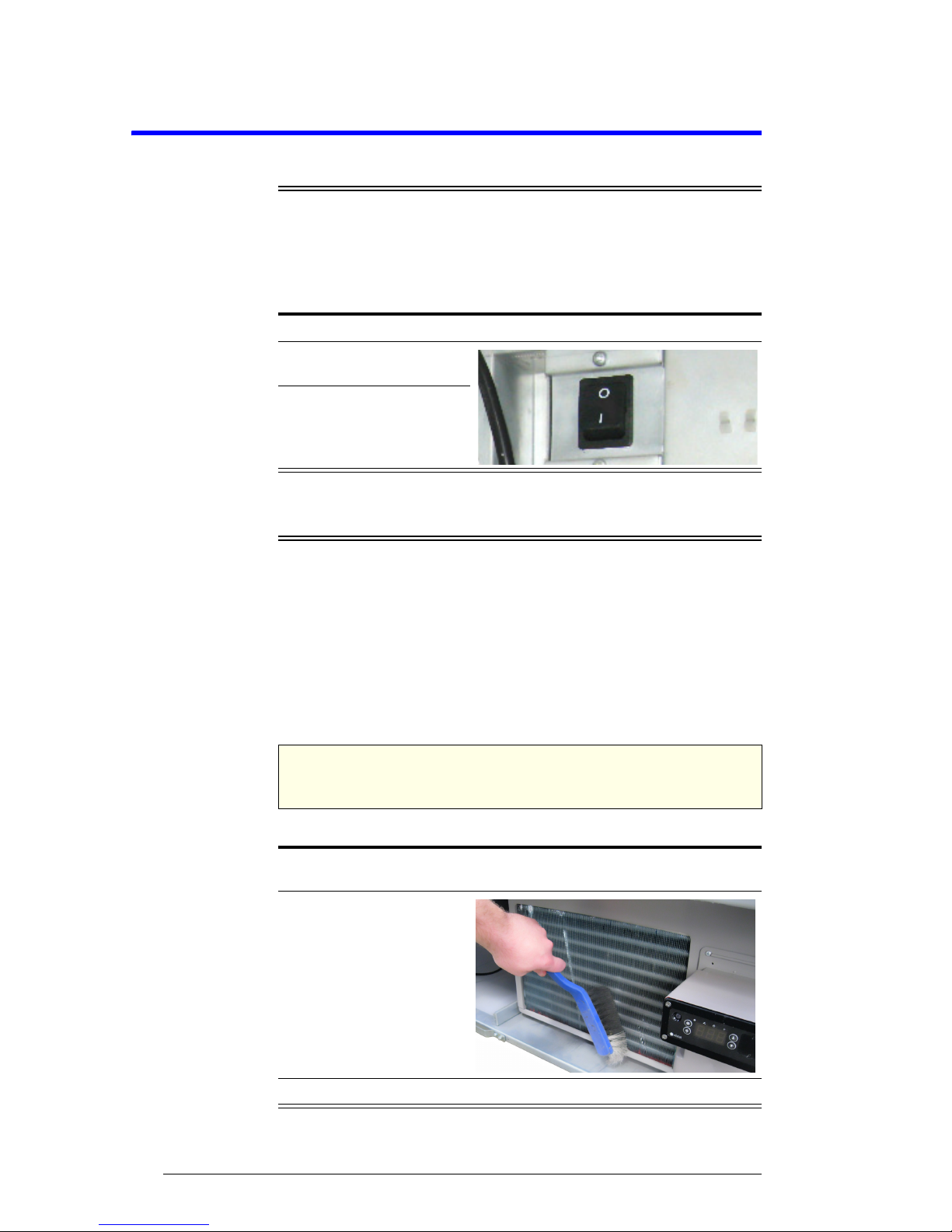
To clean the condenser coil
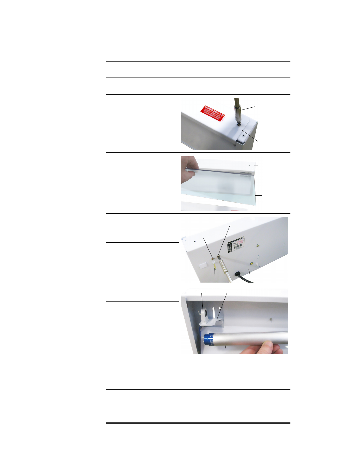
1. Fully open the cabinet door and unscrew the front panel.
2. Remove the front panel
from the cabinet.
3. Turn off the power to the
cabinet (0) at the isolating
switch.
WARNING
Isolate the cabinet from the power supply before cleaning the
condenser coil.
1. Remove the front panel and isolate the chiller from the mains power supply
(see above).
2. Clean the condenser coil
with a soft brush.
3. Reconnect the chiller to the power supply and refit the front panel.
Page 13
13
SKOPE B600-2/B600G-2
Servicing
User Manual
Lighting
This chiller is designed for use with LED tubes and is not compatible with
fluorescent tubes.
Interior Light The cabinet interior is lit by one 19 Watt T8 LED tube (Ø26mm x 1200mm),
which can be replaced without moving shelves or removing product.
To replace the cabinet interior light
IMPORTANT
DO NOT use fluorescent tubes.
1. Remove the front panel and isolate the chiller from the mains power supply
(see previous page).
2. Remove the diffuser by squeezing it until it is released from the aluminium
housing, and then push the diffuser out of the way.
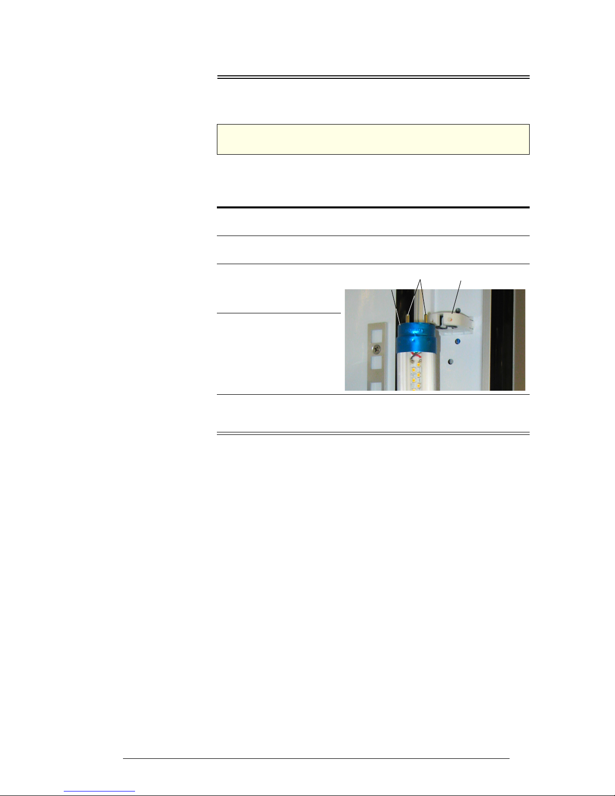
3. Rotate the LED tube until
the pins on the ends of the
tube align with the slots,
then slide it out.
4. Fit a new LED tube.
Note: the pointer at each
end of the tube should be
set to the “0” position.
5. Refit the diffuser by slipping the back section into the housing, then
squeezing and snapping the front section of the diffuser into place as you
work down the length of the light.
Pins
Lamp Holder
LED Tube
(partially removed)
Page 14
14
Servicing
User Manual
SKOPE B600-2/B600G-2
Sign Light B600G-2 only. The sign unit is lit by one 11 Watt T8 LED tube (Ø26mm x
600mm), which can be replaced by removing the front sign panel.
To replace the sign light
1. Remove the front panel and isolate the chiller from the mains power supply
(see page 12).
2. Remove the sign assembly. Lift the assembly up and off the sign sides and
unplug it from the cabinet.
3. Remove the sign top
cover by undoing the
fixing screws from the top
of the sign assembly.
4. Slide the clear front panel
(and artwork if present) up
and out of the sign
assembly.
5. Undo the two inner
lampholder fixing screws
from the rear of the sign
assembly.
6. Loosen the two outside
screws (vertical slot
screws) and slide the
lampholder brackets (and
LED tube) to the bottom of
the vertical slots.
7. Rotate and remove the
failed LED tube.
8. Fit the new LED tube.
9. Slide the lampholder brackets (and LED tube) to the top of the vertical slots
and tighten the outside screws (vertical slots screws).
10. Screw the two inner screws back into the assembly to fix the lampholder
brackets (and LED tube) in place.
11. Refit the clear front panel (and artwork if present) and screw the sign top
cover back onto the top of the sign assembly.
12. Plug the sign assembly back into the cabinet and slot the assembly back
onto the sign sides.
Screw driver
Sign top cover
Sign Assembly
Screw driver
Inner screw (remove)
Outer screw (loosen)
Sign assembly (back)
Vertical slot
Lamp holder bracket
Lamp holder
LED tube
Page 15
15
SKOPE B600-2/B600G-2
Servicing
User Manual
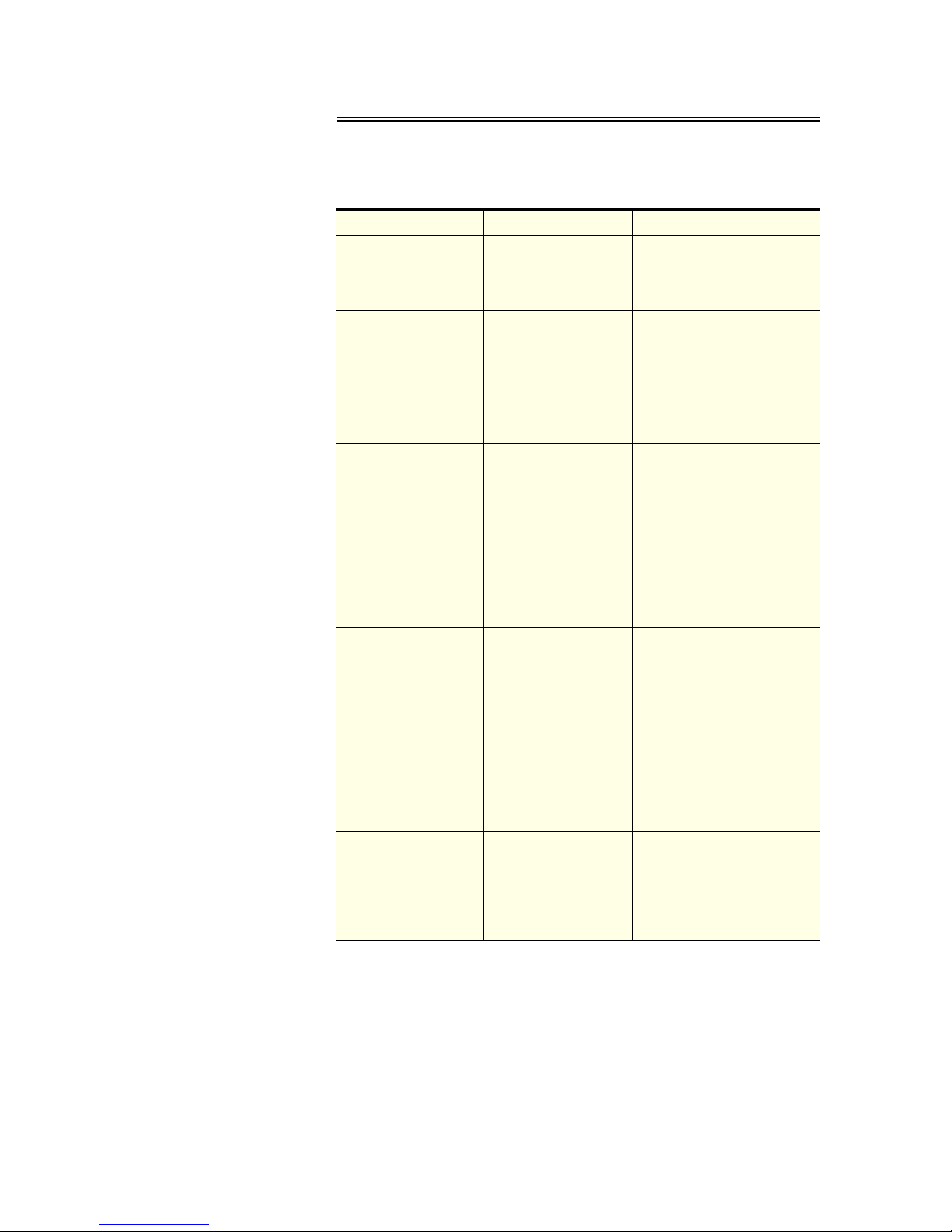
Troubleshooting
For questions about the EMS controller, see “Messages and Alarms” on
page 11. For problems with the cabinet and refrigeration cassette, use the
following table.
Problem Possible Cause Suggestions
• Cabinet not
operating
• No controller display
• Loss of power
supply
• Isolating switch
turned off
• Check mains power supply.
• Check isolating switch (see
page 12).
• Interior light not on • Failed LED tube • Replace LED tube (see
page 13).
• Controller is in
stand-by mode
• Movement in front of the
motion sensor will
reactivate it.
• Blown cabinet fuse • Contact an authorised
service agent to replace it.
• Power consumption
is higher than
expected
• Unit operating too
hot
• Clean the condenser coil
(see page 12).
• Ensure the cabinet has
good ventilation around the
refrigeration unit (see
page 5).
• Ensure the cabinet is in a
cool spot.
• Cabinet doors are
opened excessively
• Ensure doors are closed
more often.
• Product is too warm • Restricted airflow to
cabinet
• Ensure product is not
blocking airflow slots.
• Ensure there is space
around individual product
pieces.
• Controller is in
stand-by mode
• Movement in front of the
motion sensor will
reactivate it.
• Controller is in nonperishable mode
• Change the controller to
perishable mode (see
page 10).
• Warm cabinet
temperatures
• Compressor
operating for long
periods (more than 1
hour)
• Blocked condenser • Clean the condenser coil
(see page 12).
• Poor ventilation
around refrigeration
unit
• Ensure the cabinet has
good ventilation around the
refrigeration unit (see
page 5).
Page 16

SKOPE Contacts
SKOPE Industries Limited
NEW ZEALAND CONTACT
Head Office
PO Box 1091, Christchurch
New Zealand
Freephone: 0800 947 5673
Fax: (03) 983 3896
E-mail: enquiry@skope.co.nz
Website: www.skope.co.nz
AUSTRALIAN CONTACT
A.B.N. 73 374 418 306
PO Box 7543, Baulkham Hills B.C.
NSW 2153, Australia
Freephone: 1800 121 535
Fax: 1800 121 533
E-mail: enquiry@skope.com.au
Website: www.skope.com.au
Trademark Infringement
The SKOPE trademark on this product is infringed if the owner, for the time being, does
any of the following:
• Applies the trade mark to the product after their state, condition, get-up or packaging
has been altered in any manner
• Alters, removes (including part removal) or obliterates (including part obliteration) the
trade mark on the product
• Applies any other trade mark to the product
• Adds to the product any written material that is likely to damage the reputation of the
trade mark
Notice of the above contractual obligations passes to:
• Successors or assignees of the buyer
• Future owners of the product
B600-2/B600G-2
SKOPE Single Door Vertical Chiller
Type: G60EV/X5990, G60EV
User Manual
MAN10530
Rev. 2.4 Mar. 2014
© 2012 SKOPE Industries Limited. All rights reserved.
SKOPE Industries Limited reserve the right to alter specifications without notice.
is a registered trademark of SKOPE Industries Limited.
 Loading...