

Page 1

Operating and Service Manual
MAN0515 Rev. 4.0 Jan. 2006 edition
B550/660-2
BME550-2
SKOPE Gen2: Single Door Chiller
Vertical Display and Storage
Page 2

Page 3
B550/660-2, BME550-2
SKOPE Gen2: Single Door Chiller
Designed and Manufactured by
New Zealand
SKOPE INDUSTRIES LIMITED
PO Box 1091, Christchurch
New Zealand
Freephone: 0800 947 5673
Fax: (03) 983 3896
E-mail: enquiry@skope.co.nz
Website: www.skope.co.nz
Australia
SKOPE AUSTRALIA PTY LTD
A.C.N. 000 384 270
PO Box 7543, Baulkham Hills B.C.
NSW 2153, Australia
Freephone: 1800 121 535
Fax: 1800 121 533
E-mail: enquiry@skope.com.au
Website: www.skope.com.au
CONTACT ADDRESSES
i
Page 4
B550/660-2, BME550-2
SKOPE Gen2: Single Door Chiller
B550/660-2, BME550-2
SKOPE Gen2: Single Door Chiller
Operating and Service Manual
MAN0515
Rev. 4.0 Jan. 2006 edition.
Copyright © 2005
SKOPE Industries Limited.
All rights reserved.
SKOPE Industries Limited reserve the
right to alter specifications without
notice.
is a registered trade
mark of SKOPE Industries Limited.
ii
TRADE MARK INFRINGEMENT
The SKOPE trade mark on this product is infringed if the owner, for the time
being, does any of the following:
•Applies the trade mark to the product after their state, condition, get-up
or packaging has been altered in any manner
•Alters, removes (including part removal) or obliterates (including part
obliteration) the trade mark on the product
•Applies any other trade mark to the product
•Adds to the product any written material that is likely to damage the
reputation of the trade mark
Notice of the above contractual obligations passes to:
•Successors or assigns of the buyer
•Future owners of the product
Page 5

B550/660-2, BME550-2
SKOPE Gen2: Single Door Chiller
1SPECIFICATIONS
1.1Cabinet and Refrigeration Unit . . . . . . . . . . . . . . . . . . . . . . .7
2OPERATION
2.1Safety Information. . . . . . . . . . . . . . . . . . . . . . . . . . . . . . . . .8
2.2Operation of Machine . . . . . . . . . . . . . . . . . . . . . . . . . . . . . .9
Refrigeration Unit. . . . . . . . . . . . . . . . . . . . . . . . . . . . .9
Electronic Controller. . . . . . . . . . . . . . . . . . . . . . . . . . .9
Cabinet Lighting. . . . . . . . . . . . . . . . . . . . . . . . . . . . .10
Mains Isolating Switch . . . . . . . . . . . . . . . . . . . . . . . .10
2.3Shelving. . . . . . . . . . . . . . . . . . . . . . . . . . . . . . . . . . . . . . . .11
Loading Product. . . . . . . . . . . . . . . . . . . . . . . . . . . . .11
2.4Cleaning . . . . . . . . . . . . . . . . . . . . . . . . . . . . . . . . . . . . . . .12
3ELECTRONIC CONTROLLER
3.1Controller Display . . . . . . . . . . . . . . . . . . . . . . . . . . . . . . . .13
Meaning of LEDs . . . . . . . . . . . . . . . . . . . . . . . . . . . .14
3.2Controller Operation . . . . . . . . . . . . . . . . . . . . . . . . . . . . . .14
3.3Programming Controller . . . . . . . . . . . . . . . . . . . . . . . . . . .15
3.4Parameters . . . . . . . . . . . . . . . . . . . . . . . . . . . . . . . . . . . . .18
3.5Alarm Displays. . . . . . . . . . . . . . . . . . . . . . . . . . . . . . . . . . .19
Alarm Recovery . . . . . . . . . . . . . . . . . . . . . . . . . . . . .19
3.6Replacement. . . . . . . . . . . . . . . . . . . . . . . . . . . . . . . . . . . .20
Controller NTC Probe Resistance . . . . . . . . . . . . . . .20
Controller Removal . . . . . . . . . . . . . . . . . . . . . . . . . .21
Replacement Controller. . . . . . . . . . . . . . . . . . . . . . .22
Dixell Controller Wiring. . . . . . . . . . . . . . . . . . . . . . . .23
4SERVICE INSTRUCTIONS
4.1Interior Side Light . . . . . . . . . . . . . . . . . . . . . . . . . . . . . . . .24
4.2Door. . . . . . . . . . . . . . . . . . . . . . . . . . . . . . . . . . . . . . . . . . .25
4.3Sign Unit . . . . . . . . . . . . . . . . . . . . . . . . . . . . . . . . . . . . . . .29
TABLE OF CONTENTS
iii
Page 6
B550/660-2, BME550-2
SKOPE Gen2: Single Door Chiller
4.4Refrigeration Unit. . . . . . . . . . . . . . . . . . . . . . . . . . . . . . . . 33
To Remove the Refrigeration Unit . . . . . . . . . . . . . . 34
To Re-Install the Refrigeration Unit. . . . . . . . . . . . . . 36
Refrigeration Unit Junction Box . . . . . . . . . . . . . . . . 37
Evaporator Fan Motor Assembly . . . . . . . . . . . . . . . 38
Condenser Fan Motor Assembly . . . . . . . . . . . . . . . 39
Cleaning the Condenser Coil . . . . . . . . . . . . . . . . . . 40
Recommended Service Procedures. . . . . . . . . . . . . 41
For a Suspected Refrigerant Problem . . . . . . . . . . . 41
Short of Refrigerant. . . . . . . . . . . . . . . . . . . . . . . . . . 41
Compressor Not Pumping Efficiently . . . . . . . . . . . . 42
Capillary Restriction . . . . . . . . . . . . . . . . . . . . . . . . . 42
Refrigerant R134a Handling Precautions. . . . . . . . . 43
4.5Cabinet Wiring Junction Box . . . . . . . . . . . . . . . . . . . . . . . 44
4.6Mains Isolating Box . . . . . . . . . . . . . . . . . . . . . . . . . . . . . . 46
4.7Pressure Temperature Chart . . . . . . . . . . . . . . . . . . . . . . . 47
4.8Troubleshooting Chart . . . . . . . . . . . . . . . . . . . . . . . . . . . . 48
5WIRING DIAGRAM
5.1Model: B550/660-2, BME550-2 . . . . . . . . . . . . . . . . . . . . . 52
6SPARES
6.1Cabinet Assembly . . . . . . . . . . . . . . . . . . . . . . . . . . . . . . . 54
6.2Interior Side Light. . . . . . . . . . . . . . . . . . . . . . . . . . . . . . . . 55
6.3Cabinet Wiring Junction Box . . . . . . . . . . . . . . . . . . . . . . . 56
6.4Mains Isolating Box . . . . . . . . . . . . . . . . . . . . . . . . . . . . . . 57
6.5Door . . . . . . . . . . . . . . . . . . . . . . . . . . . . . . . . . . . . . . . . . . 58
6.6Sign Unit. . . . . . . . . . . . . . . . . . . . . . . . . . . . . . . . . . . . . . . 59
6.7Refrigeration Unit: UB40AAC. . . . . . . . . . . . . . . . . . . . . . . 60
6.8Refrigeration Unit: UB30AAC. . . . . . . . . . . . . . . . . . . . . . . 61
TABLE OF CONTENTS
iv
Page 7
7
B550/660-2, BME550-2
SKOPE Gen2: Single Door Chiller
1.1Cabinet and Refrigeration Unit
Table 1: Specifications
Cabinet Construction
Exterior / Interior: White powdercoat on galvanised steel
Insulation:
50mm thick, polyurethane foam
Cyclo-iso Pentane blowing agent: C5H10/C5H
12
Dimensions
Model: B550-2 B660-2 BME550-2
Height: 2195mm 2195mm 1995mm
Width: 740mm 800mm 740mm
Depth: 750mm 800mm 750mm
Floor area:
0.56m
2
0.6m
2
0.56m
2
Internal volume: 558 litres 658 litres 558 litres
Refrigeration
Electronic controlled, bottom mounted SKOPE refrigeration unit
Model: UB40AAC UB30AAC
Nominal capacity: 581 Watts 581 Watts
Compressor: Electrolux GLY90RA Electrolux GLY90RA
Refrigerant: R134a / 465 grams R134A / 465 grams
Electrical
230-240 Volts a.c. 50 Hz, single phase power supply
Run Amps: 2.15 A 2.36 A 1.96 A
Interior Lighting
Either 1 or 2 vertical 28 Watt T5 fluorescent tubes (Ø16mm x 1150mm)
Illuminated Sign
1 x 14 W T5 fluorescent tube (Ø16mm x 550mm) No sign fitted
Door
Self-closing, aluminium framed, double glazed, toughened safety glass
Shelves
5 adjustable shelves 4 adjustable shelves
SPECIFICATIONS
1
Page 8
8
B550/660-2, BME550-2
SKOPE Gen2: Single Door Chiller
2.1Safety Information
When using any electrical appliance, safety precautions should
always be observed. Read these instructions carefully, and retain for
future reference.
•When used by, or near, young children or infirm persons, close
supervision is necessary. Young children should be supervised
to ensure that they do not play with the appliance.
•Do NOT use this appliance for other than its intended use.
•Do NOT cover the grilles or block the entry or exhaust of airflow
by placing objects up against the refrigeration units.
•Do NOT probe any opening.
•Only use this appliance with voltage specified on the rating label.
•Ensure adequate ventilation of the SKOPE refrigeration units.
•Be careful not to touch moving parts and hot surfaces.
•Regulations require that all electrical work be carried out by
authorised persons. For your own safety, and that of others,
ensure this is done.
•If the supply cord becomes damaged, it must be replaced by a
SKOPE authorised service agent, or similarly qualified person,
in order to avoid a hazard.
•If the refrigeration units are required to be installed or removed
from the cabinet, ensure all necessary safety precautions are
observed.
Warning: Do NOT overload the power supply.
Caution:
Disconnect the cabinet from the mains power supply before
attempting any electrical servicing, cleaning or maintenance.
OPERATION
2
Page 9
9
B550/660-2, BME550-2
SKOPE Gen2: Single Door Chiller
2.2Operation of Machine
Plug in the machine and check operation of the refrigeration unit,
electronic controller and cabinet lighting.
Refrigeration Unit
On initial startup the evaporator and condenser fans and the
compressor will operate. This may be verified by listening for
compressor switch on and checking air movement out of the slots in
the front kick panel. The internal cabinet air will continue to circulate
at all times, as the evaporator fans operate continuously.
The compressor should switch off when the cabinet internal
temperature reaches approximately +2°C. and switch on again at
approximately +4°C.
A fan reversing device reverses the condenser fan motor for a
period of time during the compressor ‘off-cycle’. This rotation
change is to assist with self-cleaning of the condenser coil.
Otherwise, the condenser fan operates continuously in a clockwise
(LE) direction.
The two evaporator fans, located inside the evaporator box, operate
continuously. Both evaporator fans operate in contra rotation, hence
there are dedicated left and right hand blades and different wiring for
the fan motors. Correct airflow, as viewed from the rear, of the unit
left hand fan is clockwise and the right hand fan is anti-clockwise.
Electronic Controller
On initial startup, the electronic controller will either display the
internal cabinet temperature or the controller set point. The
compressor ‘on’ LED will indicate when the compressor is operating.
The controller is located in the front kick panel (see page 14 for
further controller operation).
OPERATION
2
Page 10
10
B550/660-2, BME550-2
SKOPE Gen2: Single Door Chiller
Cabinet Lighting
On initial startup, the lights which illuminate the cabinet interior and
top sign (when fitted) will come on and stay on permanently. The
lights will require a period of time to stabilise following initial start up.
Mains Isolating Switch
This cabinet is fitted with a mains isolating switch and IEC
(appliance) socket, located in the refrigeration unit compartment
(see Figure 1 below). The isolating switch and socket can be used
to isolate all cabinet and unit electrics, without unplugging the
cabinet from the wall. Ensure the mains isolating switch is turned
back on after servicing.
Figure 1: Isolating Switch
Isolating Switch
IEC Socket
Refrigeration Unit
Mains Flex
OPERATION
2
Page 11
11
B550/660-2, BME550-2
SKOPE Gen2: Single Door Chiller
2.3Shelving
The chiller is supplied with either four or five cabinet shelves, which
may be positioned at different heights to suit various products. Each
shelf is held in place with four shelf clips, which engage in each of
the four shelf support strips. The support strips are marked with a ‘+’
for easy location of shelf clips (see Figure 2 below).
Loading Product
When loading the cabinet shelves with product:
•For even cooling and efficient operation, allow air space around
packages etc.
•Do not allow products to overhang the front of the shelf as this
could prevent the door from shutting or cause glass breakage.
• Leave an airspace of at least 75mm (3") above packages etc.
on the top shelf.
Figure 2: Shelf Clip
Shelf Support Strip
Shelf Clip
‘+’ Mark
Shelf
OPERATION
2
Page 12
12
B550/660-2, BME550-2
SKOPE Gen2: Single Door Chiller
2.4Cleaning
When necessary, wipe both the interior and exterior of the cabinet
with a damp cloth. The exterior of the cabinet may be also be waxed
with automobile polish for extra protection. Ensure the cabinet is
disconnected from the mains power supply before cleaning.
Periodic cleaning of the condenser coil is also recommended (see
page 40 for cleaning instructions).
Caution:
Disconnect the cabinet from the mains power supply before
cleaning.
OPERATION
2
Page 13
13
B550/660-2, BME550-2
SKOPE Gen2: Single Door Chiller
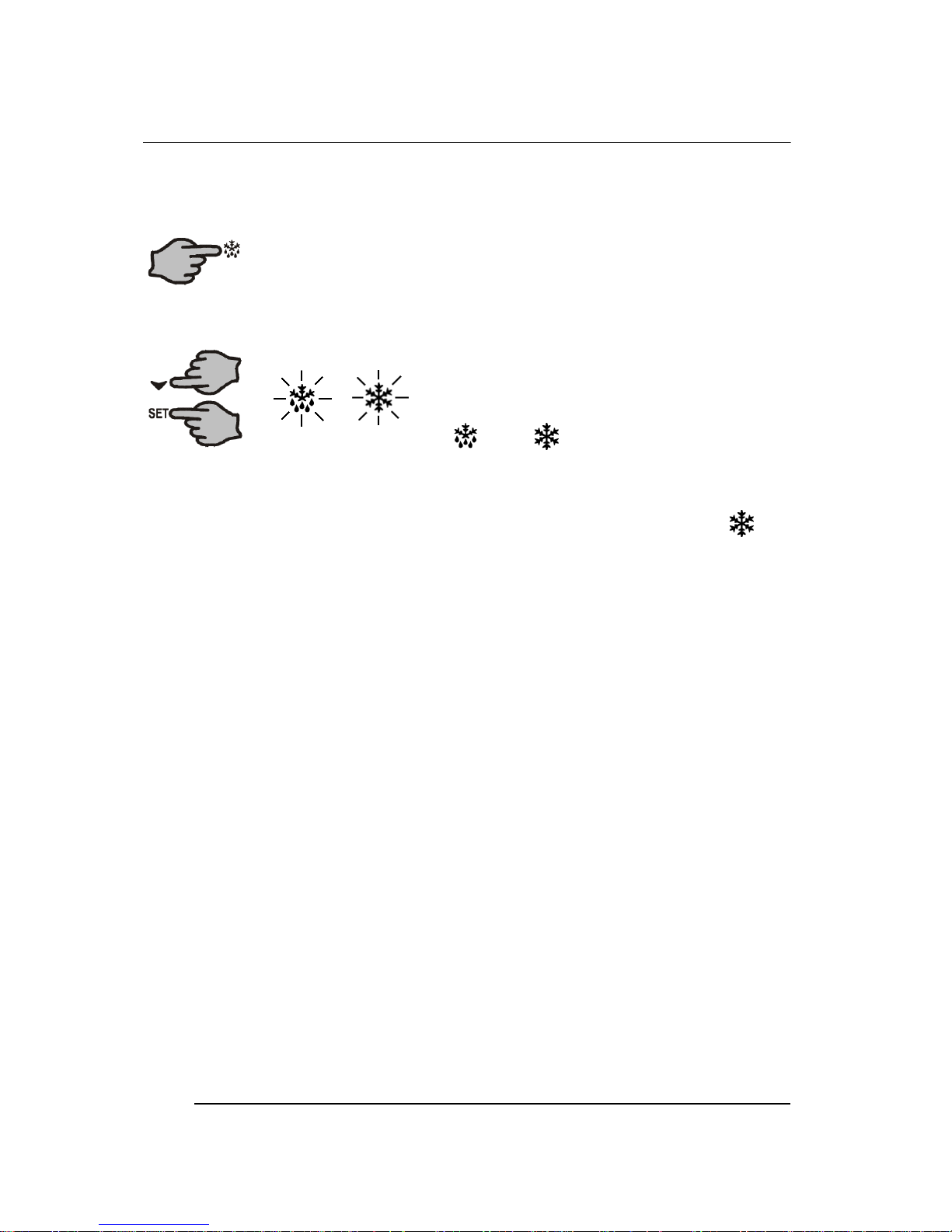
3.1Controller Display
Table 2: Controller Operation
Item KeyFunction
1
SET: Press to display target set point. In programming mode it selects
a parameter or confirms an operation
2
DEFROST: Press to start a manual defrost
3
UP: Press to see maximum stored temperature. In programming mode
it browses the parameter codes, or increases the displayed value
4
DOWN: Press to see the minimum stored temp. In programming mode
it browses the parameter codes, or decreases displayed value
5
Compressor on LED indicator
6
Defrost cycle on LED indicator
7
Set Point displayed LED indicator
8
Decimal point LED indicator
Key Combinations:
Press both keys simultaneously, to lock and unlock the keypad
Press both keys simultaneously, to enter the programming mode
Press both keys simultaneously, to return to room temperature display
1
35
2
4
6
7
8
Figure 3: Controller Display
+
+
+
ELECTRONIC CONTROLLER
3
Page 14
14
B550/660-2, BME550-2
SKOPE Gen2: Single Door Chiller
Meaning of LEDs
Table 3: LED Functions
3.2Controller Operation
The SKOPE electronic controller controls and displays the cabinet
temperature. The preset temperature setting controls the product
temperature between 2°C and 4°C.
The electronic controller also signals system and temperature
alarms (see Table 5 on page 19).
To ensure efficient operation, the electronic controller has a built in
minimum off cycle time of 3 minutes and features regular timed
defrost cycles. During the defrost cycle, the compressor switches off
and the evaporator fan stays on.
The controller has two temperature probes; one is used for the
cabinet temperature control and display, while the other probe is
used for the condenser over-temperature alarms.
LEDModeFunction
ONCompressor enabled
FlashingAnti-short cycle delay enabled
ONDefrost enabled
FlashingDrip time in progress
FlashingProgramming mode (see page 16)
ONTemperature alarm (see page 19)
+
ELECTRONIC CONTROLLER
3
Page 15
15
B550/660-2, BME550-2
SKOPE Gen2: Single Door Chiller
3.3Programming Controller
The controller keypad must always be locked, to prevent
unauthorised modification.
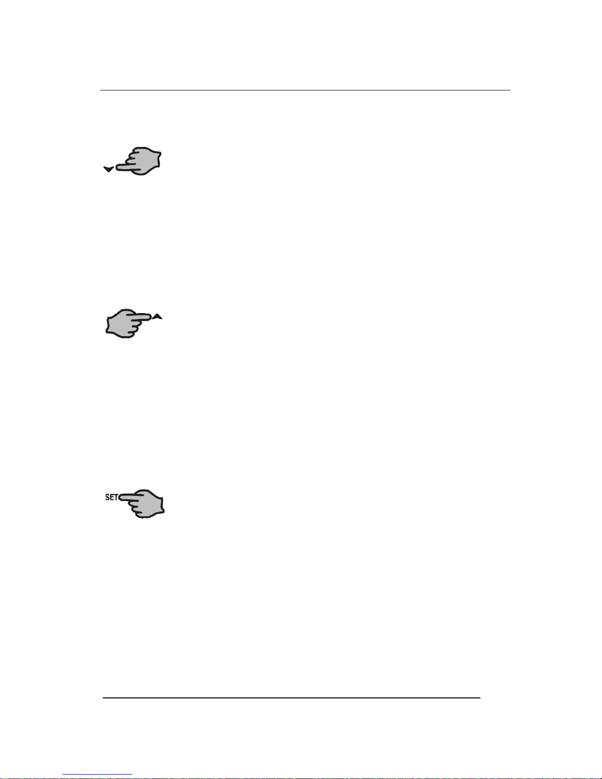
To Unlock the Keypad (to modify parameters)
Press both the UP and DOWN keys
simultaneously until ‘Pon’ is displayed.
To Lock the Keypad
1.Press and hold both the UP and DOWN
keys together for more than 3 seconds.
2. The ‘PoF’ message will be displayed and
the keypad will be locked. At this point it will be possible only to
see the Set Point or maximum or minimum temperature stored.
3.If a key is pressed for more than 3 seconds, the ‘PoF’ message
will be displayed.
To Display the Set Point
Press and immediately release the SET key. The
display will show the Set Point value and the Set Point
LED will be highlighted.
To Change the Set Point
1. Push and hold the SET key for
more than 2 seconds.
2. The value of the Set Point will be
displayed, and the LED will start blinking.
3.To change the Set value, push the UP or DOWN keys.
4.To memorise the new Set Point value, push the SET key again
or wait 15 seconds.
ELECTRONIC CONTROLLER
3
Page 16
16
B550/660-2, BME550-2
SKOPE Gen2: Single Door Chiller
To Start a Manual Defrost
Push and hold the DEFROST key for more than 2
seconds.
To Change a Parameter Value
1. Enter the programming mode by
pressing and holding both the
SET and DOWN keys for 3 sec.
(and start flashing).
2.Select the required parameter.
3.Press the SET key to display the Set value (now only the
LED is flashing).
4.Press the UP or DOWN keys to change the Set value.
5.Press the SET key to store the new value and move to the
following parameter.
6.To exit: Press both the SET and UP keys, or wait 15 seconds
without pressing any keys.
7.To lock in new parameter value: after one minute operation,
disconnect and reconnect cabinet into the mains power supply.
Notes:
1.The Set value is stored even when the procedure is exited, by
waiting for the time-out to expire.
2.Dependent on customer requirements, the SKOPE electronic
controller may have different parameter configurations (see
‘Controller Parameters’ in Table 4 on pages 18). To ensure the
controller is programmed with the correct SKOPE program,
check the program number printed on the controller box
(parameter configuration 160 = Beverage, and 170 = Food).
ELECTRONIC CONTROLLER
3
Page 17
17
B550/660-2, BME550-2
SKOPE Gen2: Single Door Chiller
To See the Minimum Temperature
1.Press and release the DOWN key.
2.The ‘Lt’ message will be displayed, followed by the minimum
temperature.
3.Press the DOWN key again, or wait 5 seconds, to restore the
normal display.
To See the Maximum Temperature
1.Press and release the UP key.
2.The ‘Ht’ message will be displayed, followed by the maximum
temperature recorded.
3.Press the UP key again, or wait 5 seconds, to restore the
normal display.
To Reset the Maximum and Minimum
Temperature
1.Press and hold the SET key for more than 3 seconds, while the
maximum or minimum temperature is displayed. The ‘rSt’
message will be displayed.
2.To confirm the operation, the ‘rSt’ message starts flashing and
the normal temperature will be displayed.
ELECTRONIC CONTROLLER
3
Page 18
18
B550/660-2, BME550-2
SKOPE Gen2: Single Door Chiller
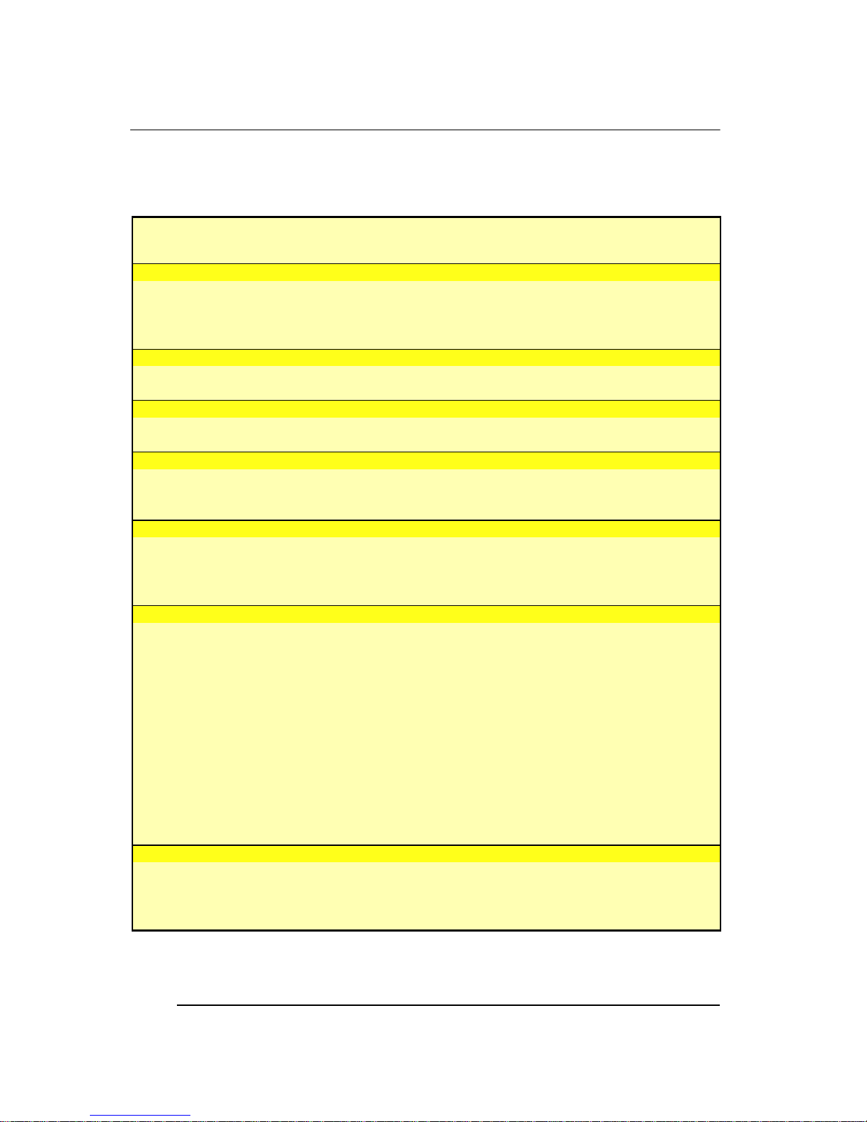
3.4Parameters
Table 4: Controller Parameters
Parameters
Display Beverage
160
Food
170
Range Description of Parameter
SET POINT PARAMETERS
Set 2 1 LS to US Set Point
Hy 2 2 0.1°C to 25.5°C Differential
LS 1 -1 -50°C to Set Minimum Set Point
US 15 5 Set to 150°C Maximum Set Point
PROBE PARAMETERS
Ot -0.7 0 -12°C to 12°C Thermostat probe calibration
OE 0 0 -12°C to 12°C Condenser probe calibration
CONTROL PARAMETERS
OdS 0 0 0 to 255 minutes Outputs delay at start up
AC 3 3 0 to 50 minutes Anti-short cycle delay
DISPLAY PARAMETERS
CF °C °C °C / °F Temperature measurement unit
rES dE in in / dE Resolution
LoD P1 P1 P1 / P2 or SP Local display
DEFROST PARAMETERS
IdF 6 6 1 to 120 hours Interval between defrost cycles
MdF 12 12 0 to 255 minutes Maximum length for defrost
dFd dEF dEF rt / it / Set / DEF Displaying during defrost
dAd 20 20 0 to 255 minutes Maximum display delay after defrost
ALARM PARAMETERS
ALc Ab Ab rE / Ab Temperature alarms configuration
ALU 12 7 up to 150°C Maximum temperature alarm
ALL -2 -2 -50°C to ALU Minimum temperature alarm
AtH 1 1 0.1°C to 25.5°C Differential for temperature alarm in cabinet
ALd 240 120 0 to 255 minutes Temperature alarm delay
dAO 24 24 0 to 23.5 hours Delay of temperature alarm at start up
tbA n n n = no / y = yes Alarm relay silencing
PA2 58 58 -40°C to AU2 Condenser over temperature
AU2 65 65 -40°C to 110°C AUE Condenser alarm temperature
ACH 5 5 0.1°C to 25.5°C Differential for condenser alarm temp recovery
dL2 2 2 0 to 255 minutes Condenser alarm delay
dA2 0 0 0 to 23.5 hours Condenser alarm temperature delay at start up
AOP CL CL OP / CL Alarm relay polarity
OTHER PARAMETERS
dP1 - - - Thermostat probe read out
dP2 - - - Condenser probe read out
rEL - - - Software release
Ptb - - - Map code
ELECTRONIC CONTROLLER
3
Page 19
19
B550/660-2, BME550-2
SKOPE Gen2: Single Door Chiller
ELECTRONIC CONTROLLER
3
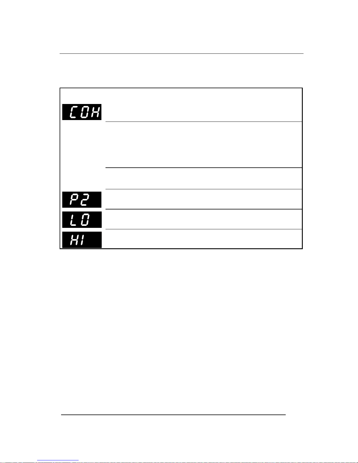
3.5Alarm Displays
Table 5: Controller Alarm Displays
Note: The refrigeration system and cabinet lighting shut down with
‘P1, P2 and CSd’ alarms.
Alarm Recovery
•Condenser Stage ONE over-temperature alarm (COH) recovers
when the condenser is either cleaned or cools down.
•Condenser Stage TWO over-temperature alarm (CSd) recovers
by disconnecting and reconnecting the cabinet mains power
supply (or isolation switch), which will reset all the alarms.
•Cabinet temperature alarms (LO and HI) automactically stop at
temperature recovery.
AlarmDescription
Stage ONE - Maintenance required:
Immediately attend condenser (for auto alarm reset).
Stage TWO - Refrigeration Shut-Down:
Condenser over-temperature has shut-down system and
cabinet lighting. Attend condenser. To reset alarm, cabinet
must be replugged into power supply. For repeat alarms,
contact an authorised service agent.
Faulty Ambient probe (internal cabinet - return air).
Refrigeration system and cabinet lighting shut down.
Faulty High Temperature probe (condenser).
Refrigeration system and cabinet lighting shut down.
Internal cabinet - LOW temperature alarm.
Alarm will stop at temperature recovery.
Internal cabinet - HIGH temperature alarm.
Alarm will stop at temperature recovery.
Page 20

20
B550/660-2, BME550-2
SKOPE Gen2: Single Door Chiller
3.6Replacement
If the SKOPE electronic controller has a suspected fault, care must
be taken to ensure accurate diagnosis. The controller has various
programmable parameters that effect operation such as time delay
and defost modes (see Table 4 on page 18).
•Any suspected failure must be double checked.
•Confirm all wiring and terminations are correct.
•Check probe resistance is correct (see Table 6 below).
•Replace any faulty components.
Controller NTC Probe Resistance
* Tolerance ± 2.4%
Table 6: NTC Probe Resistance
Temperature
Resistance*
(K Ohms)
-10°C 42.5
-5°C 34.0
0°C 27.3
5°C 22.1
10°C 18.0
20°C 12.1
30°C 8.3
40°C 5.8
50°C 4.2
ELECTRONIC CONTROLLER
3
Page 21

21
B550/660-2, BME550-2
SKOPE Gen2: Single Door Chiller
Controller Removal
1.Disconnect the cabinet from the mains power supply.
Alternatively, the cabinet can be switched off and unplugged
from the mains isolating box, located on the left hand side of
the refrigeration unit compartment. The cabinet kick panel will
need to be removed to access the mains isolating box.
2.Remove the cabinet kick panel, by loosening the two top
keyhole fixing screws and lifting the panel up and forward.
3.Loosen off the two top keyhole fixing screws that hold the
controller box assembly to the kick panel.
4.Unscrew and remove the controller box cover.
5.Release the controller fixing clips, each side of the controller.
6.Disconnect the push-on terminals from the back of controller.
7.Fitting the controller is a reversal of these instructions.
Figure 4:
Removing the Controller Box
Controller
Fixing Clip
Controller Box
Controller
Controller
Keyhole Fixing
Screws
Figure 5:
Removing the Controller
Push-on Terminals
Cabinet Kick
Panel
ELECTRONIC CONTROLLER
3
Page 22

22
B550/660-2, BME550-2
SKOPE Gen2: Single Door Chiller
Replacement Controller
The Dixell XR30C, ELZ0471, controller has been replaced by the
Dixell XR30C, ELZ0471B (Rev B) electronic controller.
The Dixell XR30C ELZ0471B Rev B controller provides identical
functionality in an essentially identical housing. The only difference
in the two models is the connection terminals at the rear of the
controller. The Dixell XR30C Rev A controller (see Figure 7) uses a
low insertion force right-angled socket. The XR30C Rev B controller
(see Figure 6) uses five standard right-angled 6.3mm Q.C. PCB
mount terminals, providing a more reliable connection.
This change is effective from February 2005, cabinet serial no.
A050212714.
Figure 7:
Dixell XR30C ELZ0471
Rev A Controller
Figure 6:
Dixell XR30C ELZ0471B
Rev B Controller
ELECTRONIC CONTROLLER
3
Page 23

23
B550/660-2, BME550-2
SKOPE Gen2: Single Door Chiller
Dixell Controller Wiring
The wiring configuration has also been simplified to eliminate one of
the two external loop wires (see Figures 8 and 9 below).
Note: The arrangement of the order of the connections and position
of the external loop wire differs between the two variations.
However, the connections at the refrigeration system electrical
junction box remain the same.
Figure 9:
Dixell XR30C ELZ0471
Rev A Controller
Figure 8:
Dixell XR30C ELZ0471B
Rev B Controller
ELECTRONIC CONTROLLER
3
Page 24

24
B550/660-2, BME550-2
SKOPE Gen2: Single Door Chiller
4.1Interior Side Light
The cabinet can have one or two interior side lights. Each side light
houses one 28 Watt T5 fluorescent tube, which may be replaced
without removing shelves or product from the cabinet. To replace
the fluorescent tube:
1.Disconnect the cabinet from the mains power supply.
2.Remove the side light diffuser, by compressing the back
section of the diffuser until it disengages from the aluminium
housing and then push the diffuser back (see Figure 10 below).
3.The fluorescent tube can now be removed. Revolve the tube
until the pin position allows withdrawal.
4.When refitting the new fluorescent tube ensure the printing on
the tube is at the bottom, as the tube orientation is important.
5.When refitting the diffuser, engage the back section into the
housing, and then compress and snap the front section of
diffuser back into place working down the full length of the light.
Fluorescent Tube
Diffuser
Figure 10: Replacing the Fluorescent Tube
SERVICE INSTRUCTIONS
4
Page 25

25
B550/660-2, BME550-2
SKOPE Gen2: Single Door Chiller
4.2Door
Alignment
Door alignment can be achieved by removing the kick panel and
releasing the bottom hinge fixing bracket. The brackets are provided
with slots allowing alignment adjustment.
Gasket Replacement
The door gasket clips into the door frame extrusion and may be
removed for repair or replacement simply by peeling from the frame,
starting at a corner (see Figure 11 below).
Should the gasket be out of shape when in place, use hot air (i.e.
from hair drier) to realign.
Figure 11: Door Gasket Removal
Door Gasket
Gasket Retainer
Door Frame
SERVICE INSTRUCTIONS
4
Page 26

26
B550/660-2, BME550-2
SKOPE Gen2: Single Door Chiller
Door Tension
The glass door has an internal torsion bar, pretensioned at the
factory, which enables the door to self-close. If necessary, door
tension can be further adjusted by rotating the capstan mounted in
the bottom hinge bracket. To adjust the door tension:
1.Slowly release tension on the capstan, by turning the capstan
with a Ø2.5mm steel rod and removing the split pin.
2.With the aid of another Ø2.5mm steel rod, increase the tension
by turning the capstan in the direction the door closes.
3.Once adequate tension has been achieved, re-insert the split
pin through the hole in the hinge bracket to lock in position.
4.To check door tension; hold the door open approximately
100mm and let go of the door. The door should gently close
with the door gasket forming an air tight seal with the cabinet.
In the event the door tension can no longer be adjusted, the torsion
bar may need replacing (see ‘Torsion Bar Replacement’, page 27).
Figure 12: Door Tension
Capstan
Split Pin
Bottom Hinge Bracket
Door
SERVICE INSTRUCTIONS
4
Page 27
27
B550/660-2, BME550-2
SKOPE Gen2: Single Door Chiller
Torsion Bar Replacement
The torsion bar assembly is located inside the door frame and can
be replaced if necessary. To replace the door torsion bar assembly:
1.Remove the door from cabinet (see ‘Door Removal’, page 28).
2.Carefully lever out the bottom bush from the door frame and
pull old torsion bar out from the door frame. The end of the
torsion bar will need manoeuvring, to allow the ‘flat hook’ end to
clear the hinge hole.
3.Remove the existing capstan and bush from the old torsion bar.
4.Thread the capstan, complete with the bush, over the ‘round
hook’ end of the new torsion bar (see Figure 13 below). Ensure
the aluminium tube moves freely up and down the torsion bar.
5.Fit the new torsion bar assembly into the door frame. When the
torsion bar is correctly installed, the capstan should not turn.
6.Lightly tap the bottom of the capstan into the hinge hole, until
the bush is flush with the door frame.
7.Refit the door to the cabinet and adjust the tension (see ‘Door
Tension’ on page 26).
Figure 13: Door Torsion Bar Assembly
Torsion Bar
‘round hook end’
Door Bush
Capstan
Door Frame
SERVICE INSTRUCTIONS
4
Page 28

28
B550/660-2, BME550-2
SKOPE Gen2: Single Door Chiller
Door Removal
For ease of servicing and reversing hinging, the door can be
removed from the cabinet. To remove the door:
1.Disconnect the cabinet from the mains power supply.
2.Slowly release tension on the door capstan, by turning the
capstan with a Ø2.5mm steel rod and removing the split pin
from the bottom hinge bracket.
3.Unscrew the bottom hinge. Important: ensure the weight of the
door is fully supported, before removing the bottom hinge.
4.The door and hinge can now be removed from the cabinet.
To refit the door:
1.Lift the door onto the top hinge pin. The weight of the door will
need supporting, until the bottom hinge is fitted.
2.Locate bottom hinge onto door capstan and attach to cabinet.
3.Check alignment with other doors and adjust as necessary.
4.Re-tension the door (see ‘Door Tension’ on page 26).
Hinge Reversal
The glass door can be hinged on either the left or right hand side. To
reverse the door hinging opposite hand top and bottom hinges are
required.
1.Remove the door (see ‘Door Removal’ above).
2.Remove the existing top and bottom hinges and replace with
the opposite hand hinges (see page 58 for part numbers).
3.Remove the torsion bar assembly from the door.
4.Refit torsion bar assembly into the opposite end of the door.
5.Refit top door bush.
6.Refit the door to the cabinet (see ‘Door Removal’, above).
7.Re-tension the door (see ‘Door Tension’ on page 26).
SERVICE INSTRUCTIONS
4
Page 29

29
B550/660-2, BME550-2
SKOPE Gen2: Single Door Chiller
4.3Sign Unit
The illuminated sign unit, located on top of the cabinet houses a
fluorescent tube and electronic ballast. Internal access to the sign
unit may be gained with the sign unit still attached to the cabinet.
To Replace the Fluorescent Tube
To access the fluorescent tube, the curved sign panel must first be
removed from the sign unit. No tools are required for this procedure.
To remove the sign panel:
1.Disconnect the cabinet from the mains power supply.
2.Start at one of the top corners of the sign unit and pull the sign
panel out from under the sign top cover (see Figure 14 below).
3.Work along the length of the sign unit, pulling the sign panel out
as you go.
4.Carefully remove the sign panel away from the sign unit.
5.The fluorescent tube can now be accessed for replacement
(see figure 16 on page 30).
Figure 15: Sign Corner Detail
Sign Top Cover
Corner Notch
Sign Panel
End Strip
Sign Panel
Figure 14: Removing Sign Panel
Sign Top Cover
Corner
Notch
SERVICE INSTRUCTIONS
4
Page 30

30
B550/660-2, BME550-2
SKOPE Gen2: Single Door Chiller
To refit the curved sign panel:
1.Ensure both sign end strips are fitted to the sign panel.
2.Carefully fit the sign panel into the bottom sign cover, ensuring
the sign end strips are correctly positioned in both of the bottom
corner notches.
3.Locate one top corner of the sign panel into the corner notch of
the top cover. Ensure the end strip fits neatly into the corner
notch (see Figure 15 on page 29).
4.Use your thumbs to push the sign panel under the top cover,
working progressively along the full length of the panel. Ensure
the sign panel engages into the sign top along the full length of
the sign unit.
5.Ensure both the sign end strips fit neatly into the top and
bottom corner notches.
Figure 16: Sign Unit (with sign panel removed)
Fluorescent Tube
Sign Top Cover
Sign Panel
Sign Bottom Cover
Sign Panel
End Strip
Sign Wiring Cover
SERVICE INSTRUCTIONS
4
Page 31

31
B550/660-2, BME550-2
SKOPE Gen2: Single Door Chiller
To Replace the Electronic Ballast
The electronic ballast is located inside the sign unit, mounted on the
back of the sign wiring cover. To access the electronic ballast:
1.Disconnect the cabinet from the mains power supply.
2.Remove the sign unit from the top of cabinet (see ‘To Remove
the Sign Unit’ on page 32).
3.Remove the curved sign panel (see ‘To Replace the
Fluorescent Tube’ on page 29).
4.Remove the fluorescent tube, to avoid it being damaged.
5.Remove the sign wiring cover, by undoing the four screws from
the rear of the sign unit.
6.The electronic ballast, mounted on the back of the sign wiring
cover, can now be accessed for replacement (see Figure 17
below).
Figure 17: Electronic Ballast
Electronic Ballast
Sign Wiring Cover
Connector Block
SERVICE INSTRUCTIONS
4
Page 32
32
B550/660-2, BME550-2
SKOPE Gen2: Single Door Chiller
To Remove the Sign Unit
For ease of servicing, the sign unit can be removed from the cabinet:
1.Unplug the sign unit from the cabinet roof top power supply
socket.
2.Loosen and turn the sign retaining clip on the top of each side
panel (see Figure 18 below).
3.Loosen the two screws on the back of the sign unit bracket.
4.Lift the sign unit up to separate the sign from the sign sides.
5.The sign unit can now be removed from the cabinet.
To Remove the Sign Side Panels
For ease of servicing, the sign side panels can be removed from the
cabinet. To remove the side panels:
1.Remove the sign back panel, by lifting up to disengage from
the side panels (see Figure 19 below).
2.Loosen the keyhole screws, holding side panels to cabinet top.
3.Slide the side panels forward to disengage the keyholes.
Figure 18: Sign Retaining Clip
Figure 19: Sign Back Panel
Sign Retaining Clip
Sign Side Panel
Sign Back
Panel
SERVICE INSTRUCTIONS
4
Page 33

33
B550/660-2, BME550-2
SKOPE Gen2: Single Door Chiller
4.4Refrigeration Unit
The SKOPE Cyclone® unit is a self-contained refrigeration module,
which aligns with port holes in the floor of the cabinet. Air is drawn
through the evaporator and blown up the back duct. Air returns to
the evaporator through the floor port hole.
The refrigeration unit can be isolated from the mains power, by
switching off the mains isolating switch and disconnecting the
appliance connector (unit to mains isolating box flex).
All electrical connections for the refrigeration unit are contained
inside the unit junction box, mounted on front of the refrigeration unit
(see page 37).
Figure 20: Refrigeration Unit
Unit Junction Box
Unit Side Baffle
Electronic Controller (in transit position)
Evaporator Coil
Condenser Coil
Compressor
SERVICE INSTRUCTIONS
4
Page 34

34
B550/660-2, BME550-2
SKOPE Gen2: Single Door Chiller
To Remove the Refrigeration Unit
For servicing, the refrigeration unit can be removed from the cabinet.
1.Disconnect the cabinet from the mains power supply.
2.Remove the cabinet kick panel, by loosening the screws along
the top back flange of the kick panel. Raise the kick panel
vertically to clear keyholes off the screw heads, then tilt panel
forward and lift up and off the bottom fixing brackets. Access to
top screws can be made easier by opening the cabinet door.
3.Unplug the cabinet sidelight 5-pole plug from underneath the
right hand side of the cabinet wiring junction box.
4.Unplug the cabinet roof top supply 3-pole plug from underneath
the centre of the cabinet wiring junction box.
5.Unplug the cabinet wiring junction box 3-pole plug from the
front of the refrigeration unit junction box.
Figure 21: Cabinet Wiring Junction Box
Refrigeration Unit Junction Box
3-Pole Socket
Cabinet Wiring
Junction Box
Cabinet Sidelight
5-Pole Plug
Cabinet Roof Top 3-Pole Plug
Electronic Controller
Unit Side Baffle
SERVICE INSTRUCTIONS
4
Page 35

35
B550/660-2, BME550-2
SKOPE Gen2: Single Door Chiller
6.Loosen the two keyhole screws holding the cabinet wiring
junction box to the guide rails.
7.The wiring junction box can now be lifted off the keyhole
screws and removed clear of the cabinet.
8.Switch off the isolating switch and unplug the refrigeration unit
from the mains isolating box.
9.Remove the unit bottom baffle by loosening both screws on the
bottom baffle and lifting up and off the screw heads.
10.Remove the top screws from both guide rails and pull both
guide rails down level with the unit base (this will lower the
entire refrigeration unit away from the base of the cabinet).
11.The refrigeration unit can now be pulled straight out from the
cabinet, using the diagonal white handles on either side.
12.Important: ensure the cabinet sidelight and roof top supply
flexes are drawn safely clear of the unit.
Figure 22: Isolating Switch
Isolating Switch
IEC Socket
Refrigeration Unit
Mains Flex
SERVICE INSTRUCTIONS
4
Page 36

36
B550/660-2, BME550-2
SKOPE Gen2: Single Door Chiller
To Re-Install the Refrigeration Unit
Refitting the refrigeration unit is a reversal of the removal procedure.
1.Ensure all cables, capillaries etc. are secured away from sharp,
hot or moving objects before replacing the refrigeration unit.
2.Ensure the refrigeration unit is plugged into the isolating box
and that the mains isolating switch is turned on.
3.Ensure the refrigeration unit is pushed fully home before raising
both the guide rails and locking into position.
4.Plug the cabinet wiring junction box into the refrigeration unit
junction box.
5.Important: ensure the unit bottom baffle is refitted (see Figure
21 on page 34).
6.Refit the cabinet wiring junction box and cabinet kick panel.
7.Reconnect the cabinet to the mains power supply.
Figure 23: Removing Refrigeration Unit
Refrigeration Unit
Junction Box
3-Pole Socket
Unit Side
Baffle
SERVICE INSTRUCTIONS
4
Page 37

37
B550/660-2, BME550-2
SKOPE Gen2: Single Door Chiller
Refrigeration Unit Junction Box
Electrical connections for the refrigeration unit are contained inside
the refrigeration unit junction box, mounted on the front of the refrigeration unit. Evaporator fan connections and capacitors are located
inside the evaporator motor junction boxes. To access the fan motor
connections, fan motor capacitor and fan reversing timer:
1.Disconnect the cabinet from the mains power supply.
2.Remove the kick panel, electronic controller and refrigeration
unit from the cabinet (see page 34 for removal instructions).
3.Unplug the cabinet wiring junction box plug from the cabinet
supply socket, on the front of the unit junction box.
4.Undo the two screws from front and rear of the unit junction box
and remove the cover, leaving the Earth wire attached.
5.All electrical connections can now be accessed.
6.Ensure the unit junction box cover is replaced after servicing.
Figure 24: Refrigeration Unit Junction Box
Condenser
Fan Motor
Fan Reversing Timer
Cabinet Supply Socket
Refrigeration Unit Junction Box
Fan Motor
Capacitor
Resistor
Condenser Fan
Shroud
SERVICE INSTRUCTIONS
4
Page 38

38
B550/660-2, BME550-2
SKOPE Gen2: Single Door Chiller
Evaporator Fan Motor Assembly
The evaporator fan motors can be removed from the evaporator box
as a complete assembly. To replace an evaporator fan motor:
1.Remove the refrigeration unit (see page 34).
2.Remove the cover from the refrigeration unit junction box.
3.Trace the evaporator fan motor flex to the push-on connections
inside the unit junction box and disconnect the terminals.
4.Undo the two top screws from the mounting bracket and lift out
complete evaporator fan motor ass’y (see Figure 25 below).
5.Undo two screws from motor junction box and disconnect flex.
6.Remove the fan blade and undo four screws holding fan motor.
7.Replace the fan motor capacitor inside the motor junction box.
8.Fit the new fan motor and re-assemble.
9.When refitting the evaporator fan motor assembly, reseal the
flex hole in the evaporator box.
Figure 25:
Evaporator Fan Motor Assembly
Figure 26:
Evaporator Motor Junction Box
Evaporator Fan
Motor Assembly
Evaporator Motor Junction Box
Evaporator Motor Flex
Evaporator Motor
Fan Blade
Refrigeration Unit
Junction Box
Fan Motor Capacitor
SERVICE INSTRUCTIONS
4
Page 39

39
B550/660-2, BME550-2
SKOPE Gen2: Single Door Chiller
Condenser Fan Motor Assembly
The condenser fan motor, fan blade and mounting bracket can be
removed from the refrigeration unit as a complete assembly. To
replace the condenser fan motor assembly:
1.Remove the refrigeration unit (see page 34).
2.Remove the cover from the refrigeration unit junction box (see
page 37).
3.Trace the condenser fan motor flex to the push-on connections
inside the unit junction box and disconnect the terminals.
4.Withdraw condenser fan motor flex out of the unit junction box.
5.Undo the two top fixing screws from the mounting bracket.
6.Remove the complete condenser fan motor assembly.
7.Remove the fan blade and undo four screws holding fan motor.
8.Replace the fan motor capacitor inside the unit junction box.
9.Fit new fan motor and re-assemble.
Figure 27: Condenser Fan Motor Assembly
Condenser Fan
Motor Assembly
Condenser Coil
Fixing Screws (2)
Fan Blade
Condenser Fan Motor Flex (disconnected from unit junction box)
Mounting Bracket
SERVICE INSTRUCTIONS
4
Page 40

40
B550/660-2, BME550-2
SKOPE Gen2: Single Door Chiller
Cleaning the Condenser Coil
The condenser coil MUST be kept clean for efficient and reliable
operation. Clean the condenser coil with a brush and vacuum
cleaner regularly. The condenser coil is located behind a side baffle,
on the right hand side of the refrigeration unit (see Figure 21 on p34).
To access the condenser coil:
1.Disconnect the cabinet from the mains power supply.
2.Remove the cabinet kick panel and cabinet wiring junction box
(see instructions on page 34).
3.Remove the two screws holding the side baffle to the
condenser coil and carefully pull the baffle out from the unit.
4.The condenser coil can now be accessed for cleaning. Clean
the condenser coil with a brush and vacuum cleaner.
5.Refit the side baffle and cabinet wiring junction box.
6.Refit the cabinet kick panel, and reconnect to the power supply.
Caution:
The cabinet MUST be disconnected from the mains power
supply before cleaning the condenser coil.
Figure 28: Condenser Coil
Cabinet
Kick Panel
Cabinet Wiring
Junction Box
Keyhole Fixing Screw
Cabinet Door
(open)
Condenser Coil
Kick Panel Keyhole
Fixing Screw
SERVICE INSTRUCTIONS
4
Page 41

41
B550/660-2, BME550-2
SKOPE Gen2: Single Door Chiller
Recommended Service Procedures
SKOPE recommend the SKOPE Cyclone® demountability and
exchangeability philosophy, which in essence means: The customer
must not be inconvenienced during system maintenance.
In the unlikely event of Refrigeration failure, an exchange unit is
simply swapped in a matter of minutes. There is no cabinet down
time or unloading product. In one 5 minute visit, the customer's
inconvenience ends. The faulty Cyclone® is then removed to the
workshop for repair as time allows.
For a Suspected Refrigerant Problem
Disconnect the evaporator fan motor and with the system running, a
‘frost line’ will become obvious (after approximately 8 minutes):
Entire evaporator and accumulator must be frosting. Compressor at
suction inlet will be cold and sweating.
If these conditions are not met, the system is faulty, either short of
refrigerant, compressor not pumping efficiently, or capillary
restriction. The system must then be opened (see Refrigerant
R134a Handling Precautions section) and gauges temporarily fitted
(i.e. either temporarily fit line piercing valves, or braze in service
lines).
Short of Refrigerant
Where the frosting effect is shorter than required (unless all
refrigerant is lost, where there is no frosting effect). Only a small
amount of refrigerant will exit the system. A leak test (refrigerant /
dry nitrogen mix, up to 250 psig) should be performed to locate the
leak. If no leak is found, a pressure test should be performed (dry
nitrogen only, up to 250 psig) if there is no pressure drop over 24
hours, the fault should be treated as a capillary restriction.
SERVICE INSTRUCTIONS
4
Page 42

42
B550/660-2, BME550-2
SKOPE Gen2: Single Door Chiller
Compressor Not Pumping Efficiently
Where the frosting effect is not as cold as it should be. Symptoms
include: compressor body hotter than normal, condenser cooler
than normal, and the compressor may make an unusual hissing
sound. All of these symptoms depend on the severity of the problem.
The only way to prove a pumping problem is to perform a
compressor pump-down test: braze closed compressor suction line,
Open discharge line; then run the compressor to pull a vacuum on a
vacuum gauge. The compressor should pull down to approximately
30" (inches) vacuum then turn the compressor off and this vacuum
must be held without any loss for 5 minutes. If the Compressor does
not pass these tests; it is not pumping efficiently and must be
replaced.
There are different methods to proving pumping efficiency. If the test
is performed with a system charged with refrigerant, a deep vacuum
will not be achieved.
Capillary Restriction
With a totally blocked capillary, there will be no refrigeration effect.
A partially blocked capillary may have similar symptoms to a system
being short of refrigerant. Flush a restricted capillary with dry
nitrogen. If the capillary will not clear, it must be replaced.
After the repair, the drier must be replaced (every time the
refrigeration system is opened, the drier must be replaced). The
Cyclone® must be fully evacuated and charged to the volume of
refrigerant indicated on the Cyclone® serial/rating label. All service
lines must be purged.
Finally, pinch-off the gauge process lines (or remove line piercing
valves) and braze the system closed. SKOPE recommend against
leaving service valves in the system as these are prone to leak (and
are open to abuse). Perform a final system leak test.
SERVICE INSTRUCTIONS
4
Page 43

43
B550/660-2, BME550-2
SKOPE Gen2: Single Door Chiller
Refrigerant R134a Handling Precautions
It is important to maintain dedicated HFC service equipment and
parts:
•Refrigeration gauges
•Service lines / Fittings
•Vacuum Pump
•Charging equipment
•Driers
•Compressors
•Temperature / Pressure chart
HFC (R134a) refrigeration systems require special service
procedures because of the highly hygroscopic (moisture sensitive)
polyolester (POE) compressor oil:
•The system (especially compressor) must only be open for the
very minimum time (to prevent moisture ingression). All parts
required for servicing must be at hand - before the system is
opened, and there should be no interruption until the system is
on the vacuum pump (or hermetically sealed).
•The system must not be open for longer than 20 minutes max.
•The drier must be replaced every time the system is opened.
•Clean work practices are essential.
•SKOPE recommend brazing the system closed after service - as
valves are prone to leak due to the nature of R134a.
Important:
Every time the refrigeration system is opened, the drier MUST be
replaced.
SERVICE INSTRUCTIONS
4
Page 44

44
B550/660-2, BME550-2
SKOPE Gen2: Single Door Chiller
4.5Cabinet Wiring Junction Box
The cabinet wiring junction box houses the electronic ballast,
cabinet fuse and electrical supply wiring for the cabinet. The cabinet
wiring junction box is located behind the kick panel, in front of the
refrigeration unit. The cabinet sidelight and cabinet roof top supply
plug into the cabinet wiring junction box, which in turn plugs into the
refrigeration unit junction box. For servicing, the cabinet wiring
junction box can be removed from the cabinet.
To access the Cabinet Wiring Junction Box
1.Disconnect the cabinet from the mains power supply.
2.Remove the cabinet kick panel, by loosening the screws along
the the top back flange of the kick panel. Raise the kick panel
vertically to clear keyholes off the screw heads, then tilt panel
forward and lift up and off the bottom fixing brackets. Access to
top screws can be made easier by opening the cabinet door.
3.Unplug the cabinet sidelight 5-pole plug from underneath the
right hand side of the wiring junction box.
4.Unplug the cabinet roof top supply 3-pole plug from underneath
the centre of the wiring junction box.
5.Unplug the cabinet wiring junction box 3-pole plug from the
junction box on the refrigeration unit.
6.Loosen keyhole screws from either end of wiring junction box.
7.The cabinet wiring junction box can now be lifted off keyhole
screws and removed from the cabinet.
8.Remove the three bottom screws and slide the junction box lid
down and off.
9.When refitting the cabinet wiring junction box to the cabinet,
ensure the cabinet roof top supply and sidelight flexes are both
plugged in and the cabinet wiring junction box is plugged into
the refrigeration unit junction box.
SERVICE INSTRUCTIONS
4
Page 45

45
B550/660-2, BME550-2
SKOPE Gen2: Single Door Chiller
Cabinet Junction Box Lid
3 Amp Ceramic Fuse
Electronic Ballast
ENSTO 3-Pole Socket
Cabinet Junction Box to Unit Junction Box Flex
ENSTO 5-Pole Socket
Screw Keyhole
Figure 29: Cabinet Wiring Junction Box
SERVICE INSTRUCTIONS
4
Page 46

46
B550/660-2, BME550-2
SKOPE Gen2: Single Door Chiller
4.6Mains Isolating Box
The mains isolating box houses a 2-pole isolating switch and IEC
style appliance socket, providing mains connection to the
refrigeration unit and cabinet. The mains isolating box is located in
the refrigeration unit compartment, recessed into the left hand
cabinet side. The refrigeration unit plugs directly into the mains
isolating box.
To access the mains isolating box, for servicing:
1.Disconnect the cabinet from the mains power supply.
2.Remove the cabinet kick panel and cabinet wiring junction box
(see instructions on page 34).
3.Remove the two screws from the mains isolating box and pull
out from the cabinet wall.
4.The isolating switch, IEC socket and mains supply flex can now
be replaced if necessary. See Spares section for component
part numbers.
IEC Socket
Refrigeration Unit
Mains Flex
Figure 30: Mains Isolating Box
SERVICE INSTRUCTIONS
4
Page 47

47
B550/660-2, BME550-2
SKOPE Gen2: Single Door Chiller
4.7Pressure Temperature Chart
Table 7: Pressure Temperature Chart
TEMPERATURE R134a R404A
°F °C KPa psig KPa psig
-29.2 -34 -32 9.4 71 10
-27.4 -33 -28 8.4 79 11
-25.6 -32 -25 7.3 86 13
-23.8 -31 -21 6.2 94 14
-22.0 -30 -17 5.0 103 15
-20.0 -29 -13 3.8 111 16
-18.4 -28 -9 2.6 120 17
-16.6 -27 -4 1.3 129 19
-14.8 -26 0 0.0 138 20
-13.0 -25 5 0.7 148 21
-11.2 -24 10 1.4 158 23
-9.4 -23 15 2.2 168 24
-7.6 -22 20 2.9 179 26
-5.8 -21 26 3.7 189 27
-4.0 -20 31 4.5 200 29
-2.2 -19 37 5.4 212 31
-0.4 -18 43 6.3 224 32
1.4 -17 49 7.2 236 34
3.2 -16 56 8.1 248 36
5.0 -15 63 9.1 261 38
6.8 -14 69 10.0 274 40
8.6 -13 77 11.0 288 42
10.4 -12 84 12.0 302 44
12.2 -11 91 13.0 316 46
14.0 -10 99 14.0 331 48
15.8 -9 107 16.0 346 50
17.6 -8 116 17.0 361 52
19.4 -7 124 18.0 377 55
21.2 -6 133 19.0 393 57
23.0 -5 142 21.0 410 59
24.8 -4 151 22.0 427 62
26.6 -3 161 23.0 445 65
28.4 -2 171 25.0 463 67
30.2 -1 181 26.0 481 70
32.0 0 192 28.0 500 73
33.8 1 202 29.0 519 75
35.6 2 213 31.0 539 78
37.4 3 225 33.0 559 81
39.2 4 237 34.0 580 84
41.0 5 249 36.0 601 87
42.8 6 261 38.0 623 90
44.6 7 274 40.0 645 94
46.8 8 287 42.0 668 97
48.2 9 300 44.0 691 100
50.0 10 314 46.0 715 104
SERVICE INSTRUCTIONS
4
Page 48

48
B550/660-2, BME550-2
SKOPE Gen2: Single Door Chiller
4.8Troubleshooting
Table 8: Troubleshooting - continued on next page
Complaint Possible Cause Repair
1. Cabinet not
operating
- lights etc not
going.
Loss of power supply. Check power supply.
Refrigeration shut-down. Condenser
over-temperature has shut-down
system and cabinet lighting.
Attend condenser. To reset
alarm, cabinet must be replugged into power supply.
2. Compressor
will not start
- no hum.
Fuse removed or blown. No power. Replace fuse. Check reason.
Overload protector tripped. Refer to electrical section.
Thermostat stuck in open position. Repair or replace control.
Thermostat off, due to cold location. Relocate control.
Wiring improper, or loose. Check wiring against diagram.
3. Compressor
will not start
- hums but trips
on overload
protector.
Improperly wired. Check wiring against diagram.
Low voltage to unit. Determine reason and correct.
Start capacitor defective on CSIR or
CSR motor.
Determine reason and replace.
Run capacitor defective on PSC
motor.
Determine reason and replace.
Relay failing to close. Determine reason and correct.
Replace if necessary.
Compressor motor has a winding
open or shorted.
Check resistance values.
Replace compressor if necessary.
Internal mechanical trouble in compressor.
Replace compressor.
SERVICE INSTRUCTIONS
4
Page 49

49
B550/660-2, BME550-2
SKOPE Gen2: Single Door Chiller
4.8Troubleshooting
Table 8: Troubleshooting - continued on next page
Complaint Possible Cause Repair
9. Compressor
starts, but
does not
switch off
- start
winding.
Improperly wired. Check wiring against diagram.
Low voltage to unit. Determine reason and correct.
Relay failing to open, due to welded
contacts or relay incorrectly
mounted.
Determine reason and correct.
Replace if necessary.
Run capacitor defective on CSR
motor.
Determine reason and replace.
Excessively high discharge pressure.
Clean condenser. Check power
input. Possible overcharge,
insufficient condenser cooling,
or non-condensible gasses.
Compressor motor has winding open
or shorted. Check continuity and
resistance.
Replace compressor if faulty.
Internal mechanical trouble in compressor (tight). May be lubrication.
Replace compressor.
10. Compressor
starts and
runs, but
short cycles
on overload
protector
(relay may
chatter on
RSIR, CSIR
and CSR
motors).
Additional current passing through
overload protector.
Check wiring diagram. Check
for added fan motors etc.,
connected to wrong side of
protector.
Low voltage to unit. Determine reason and correct.
Overload protector defective. Check current, replace
protector.
Run capacitor defective on CSR
motor.
Determine reason and replace.
Excessive discharge pressure. Check condenser, check
ventilation, check for restrictions
in refrigeration system.
Suction pressure too high. Check for possibility of
misapplication.
Compressor too hot - insufficient
suction gas cooling.
Check refrigerant charge (fix
leak), add if necessary. Check
return vapour temperature and
suction superheat.
Comp’r motor has a winding shorted. Replace compressor.
SERVICE INSTRUCTIONS
4
Page 50

50
B550/660-2, BME550-2
SKOPE Gen2: Single Door Chiller
4.8Troubleshooting
Table 8: Troubleshooting - continued on next page
Complaint Possible Cause Repair
9. Unit runs OK,
but short
cycles.
Overload protector. See wiring on page 52.
Thermostat: requires adjustment or
incorrectly positioned.
Adjust or relocate thermostat
probe.
10. Unit operates
long or continuously.
Unsatisfactory
cabinet temperature.
Short of refrigerant. Fix leak, and add charge.
Overcharge of refrigerant. Remove refrigerant to correct
charge.
Thermostat not reading
temperature correctly.
Check air temperature with
thermometer. Adjust offset if
required.
Evaporator has excessive load. Establish load within limits.
Evaporator coil iced. Defrost evaporator, check
refrigeration. Check
thermostat. Check door
closing, seals etc. Check
defrost.
Restriction in refrigeration system. Determine location and clear
restriction. Flush with dry
nitrogen. Replace component
if blockage will not clear.
Dirty condenser. Clean condenser. Advise
client how to regularly clean
condenser.
Inadequate air circulation. Internal: Improve air
movement, alloe airflow around
stock.
External: Remove any
restrictions to condensing
ventilation.
Compressor not pumping
efficiently.
Replace compressor.
Filter dirty (if applicable). Clean or replace.
Faulty fan motor. Check rotation. Replace if
necessary.
SERVICE INSTRUCTIONS
4
Page 51

51
B550/660-2, BME550-2
SKOPE Gen2: Single Door Chiller
4.8Troubleshooting
Table 8: Troubleshooting
Complaint Possible Cause Repair
9. Start capacitor
open, shorted
or blown.
Relay contact not opening
properly.
Clean contacts, or replace
relay if necessary.
Prolonged operation on start cycle
due to:
(a) Low voltage to unit.
(b) Improper relay.
(a) Determine reason and
correct.
(b) Replace relay.
Excessive short cycling. Determine reason for short
cycling, and correct.
Improper capacitor. Determine correct size and
replace.
10. Relay
defective or
burned out.
Incorrect relay. Check and replace.
Line voltage too high or too low. Determine reason and correct.
Excessive short cycling. Determine reason, and correct.
Relay being influenced by loose
vibrating mount.
Remount rigidly.
11. Suction line
frosted.
Evaporator fan not running. Determine reason and correct.
Overcharge of refrigerant capillary
systems.
Correct charge.
12. Unit noisy. Loose parts or mountings. Find and tighten.
Tubing rattle. Reform to be free of contact.
Bent fan blade causing vibration. Replace blade.
Fan motor bearing worn. Replace motor.
SERVICE INSTRUCTIONS
4
Page 52

52
B550/660-2, BME550-2
SKOPE Gen2: Single Door Chiller
5.1Model: B550/660-2, BME550-2
Dixell XR30C
Rev. B Controller
30
WIRING DIAGRAM
5
Page 53

53
B550/660-2, BME550-2
SKOPE Gen2: Single Door Chiller
5.1Model: B550/660-2, BME550-2
* LE denotes fan motor orientation as viewed from the lead end.
** The wiring diagram opposite shows the Rev A electronic
controller, with an insert showing the Rev B controller (see page 22
for more information on the two variations).
Item Part Description Item Part Description
1
Sign Unit
(when applicable)
21 Capacitor
2 Lamp Holder 22
Evaporator Fan Motor
(clockwise - LE) *
3
14 Watt Fluorescent Tube
OSRAM FH 14W/860
23
Evaporator Fan Motor
(anti-clockwise - LE) *
4
Single Electronic Ballast
14-35 Watt
24
Condenser Fan Motor
(clockwise - LE) *
5 3-Way ENSTO Connector 25 Mains Terminal Block
6 Foamed Cabinet 26 RFI Capacitor
7 Sidelight Assembly 27 Resistor
8 28 Watt Fluorescent Tube 28 Relay
9 Mains Flex and Plug 29 Controller Housing
10 Mains Isolating Box 30 Electronic Controller **
11 2-Pole Isolating Switch 31 Cabinet Temp Probe
12 IEC Socket Outlet 32 Condenser Temp Probe
13 5-Way ENSTO Connector 33 Start Capacitor
14 Cabinet Junction Box 34 NTC Probe
15 5-Way ENSTO Socket 35 Run Capacitor
16 3-Way ENSTO Socket 36 Start Relay
17 3-Way Connector Block 37 Electrolux Compressor
18 3 Amp Ceramic Fuse 38 Compressor Overload
19 Refrigeration Unit 39 Unit Junction Box
20 Evap Motor Bracket Ass’y
WIRING DIAGRAM
5
Page 54
54
B550/660-2, BME550-2
SKOPE Gen2: Single Door Chiller
6.1Cabinet Assembly
Part Description SKOPE P/No. Customer P/N.
Kick Panel
(B550-2, BME550-2)
V48BA/131
Kick Panel (B660-2) D66BA/131
Kick Panel Bracket V48BA/R84
SKOPE Label - black LAB7562B
SKOPE Label - white LAB7562W
Sign Side V48BA/S20
Sign Back Panel
(B550-2)
V4800/C53
Sign Back Panel
(B660-2)
D66BA/C53
Shelf (B550-2) WRKV6000/J70
Shelf (BME550-2) V6000/J70-32
Shelf (B660-2) WRKC7200/J70
Shelf Bracket V0973-99
Light Junction Box - R/H V48BA/170
Condenser Baffle UB40AA/A62-GT
Bottom Baffle UB40AA/C93-GT
Swivel Castor SXX4339
Swivel Castor - lockable SXX4539
SPARES
6
Page 55

55
B550/660-2, BME550-2
SKOPE Gen2: Single Door Chiller
6.2Interior Side Light
Part Description SKOPE P/No. Customer P/No.
T5 Side Light Assembly - R/H V48BA/L85-32
T5 Side Light Assembly - L/H V48BB/L85-32
28 Watt T5 Fluorescent Tube ELL0603
T5 Lampholder ELZ0600
Light Cover V48BA/E71
SPARES
6
Page 56

56
B550/660-2, BME550-2
SKOPE Gen2: Single Door Chiller
6.3Cabinet Wiring Junction Box
Part Description SKOPE P/No. Customer P/No.
Cabinet Junction Box Ass’y V48BA/G29
Cabinet Junction Box Base V48BA/G30-GT
Cabinet Junction Box Cover V48BA/G31-GT
ENSTO Socket - 3 Pole ELZ0499-3
ENSTO Socket - 5 Pole ELZ0499-5
ENSTO Adaptor - 3 Pole PLM0497-3
ENSTO Adaptor - 3 Pole PLM0497-5
Single Electronic Ballast ELZ0605
3 Amp Ceramic Fuse ELZ9654
Fused Terminal Block ELZ9655
Cabinet Supply Flex V48BA/X03
SPARES
6
Page 57

57
B550/660-2, BME550-2
SKOPE Gen2: Single Door Chiller
6.4Mains Isolation Box
Part Description SKOPE P/No. Customer P/No.
Mains Isolation Box Ass’y V48BA/E80
Mains Isolation Box Base V48BA/E81-GT
Mains Isolation Box Cover V48BA/E82-GT
IEC Socket Outlet ELK8880
2-Pole Isolating Switch ELS0495
Mains Flex V4800/E53
SPARES
6
Page 58

58
B550/660-2, BME550-2
SKOPE Gen2: Single Door Chiller
6.5Door
Part Description SKOPE P/No. Customer P/No.
Glass Door Assembly - R/H
(B550-2, BME550-2)
V48BA/Z04R
Glass Door Assembly - R/H
(B660-2)
D66BA/Z04R
Door Gasket
(B550-2, BME550-2)
GKT0482N
Door Gasket (B660-2) GKT0427N
Gasket Retainer - Horizontal
(B550-2, BME550-2)
V6000/766
Gasket Retainer - Horizontal
(B660-2)
Y1100/766
Gasket Retainer - Vertical D6660/765
Torsion Bar Assembly REF5014
Bush PLM5075
Capstan TUR5100
Cotter Pin FAS5076
Top Hinge Assembly - R/H V4750/388
Bottom Hinge - R/H V48BA/393
Bottom Hinge - L/H V48BA/394
SPARES
6
Page 59

59
B550/660-2, BME550-2
SKOPE Gen2: Single Door Chiller
6.6Sign Unit
Part Description SKOPE P/No. Customer P/No.
Sign Unit Assembly (packed)
(B550-2)
V48BA/S11
Sign Unit Assembly (packed)
(B660-2)
D66BA/S11
Sign End - R/H D66BA/S13
Sign End - L/H D66BA/S14
Sign Reflector (B550-2) V48BA/S15-32
Sign Reflector (B660-2) D66BA/S15-32
Curved Sign Panel (B550-2) V4800/S17V
Curved Sign Panel (B660-2)
Wiring Cover Assembly
(B550-2)
V48BA/S18
Wiring Cover Assembly
(B660-2)
D66BA/S18
Wiring Cover (B550-2) V48BA/S19-32
Wiring Cover (B660-2) D66BA/S19-32
Sign Top / Bottom Panel V48BA/S06
Sign Panel Edge Strip RUE3704RE
14 Watt T5 Fluorescent Tube ELL0601
T5 Lamp Holder ELZ0600
Single Electronic Ballast ELZ0605
Sign Flex V60BA/934
ENSTO 3-Pole Plug ELZ0500-3
SPARES
6
Page 60

60
B550/660-2, BME550-2
SKOPE Gen2: Single Door Chiller
6.7Refrigeration Unit: UB40AAC
Part Description SKOPE P/No. Customer P/No.
Refrigeration Unit Assembly UB40AAC-160ZX
Unit Base UB40AA/210-32
Foamed Evaporator Box UB40AA/376
Compressor: Electrolux CPR0464P
Condenser Coil CLS9929
Evaporator Coil CLS9930
Drier DRY8783
Run Capacitor ELC9941NC
Start Capacitor ELC9942NC
Electrolux Relay ELR9943NC
DIXELL Electronic Contoller ELZ0471SP
DIXELL NTC Probe ELZ0472
Fan Motor - Reversible ELM9917
Fan Blade - R/H (clockwise) FAN4100
Evaporator Motor Bracket UT40AA/231
Suction Line Assembly UT40AA/378
Junction Box Assembly UB40AA/R86
Junction Box Base UB40AA/R87-GT
Junction Box Cover UB40AA/R88-GT
RFI Suppression Capacitor ELC8068
Motor Capacitor ELC9142NC
HONGFA Relay ELR0494
OMRON Relay ELR6183
ENSTO Socket ELZ0499-3
Resisistor ELZ7157
Controller Flex Assembly UB40AA/E19
Mains Flex (with IEC plug) UB40AA/E53
SPARES
6
Page 61
61
B550/660-2, BME550-2
SKOPE Gen2: Single Door Chiller
6.8Refrigeration Unit: UB30AAC
Part Description SKOPE P/No. Customer P/No.
Refrigeration Unit Assembly UB30AAC-160IX
Unit Base UB40AA/210-32
Foamed Evaporator Box UB40AA/376
Compressor: Electrolux CPR0464P
Condenser Coil CLS9967
Evaporator Coil CLS0752
Drier DRY8783
Run Capacitor ELC9941NC
Start Capacitor ELC9942NC
Electrolux Relay ELR9943NC
DIXELL Electronic Contoller ELZ0471SP
DIXELL NTC Probe ELZ0472
Fan Motor - Reversible ELM9917
Fan Blade - R/H (clockwise) FAN4100
Suction Line Assembly UT40AA/378
Junction Box Assembly UB40AA/R86
Junction Box Base UB40AA/R87-GT
Junction Box Cover UB40AA/R88-GT
RFI Suppression Capacitor ELC8068
Motor Capacitor ELC9142NC
HONGFA Relay ELR0494
OMRON Relay ELR6183
ENSTO Socket ELZ0499-3
Resisistor ELZ7157
Controller Flex Assembly UB40AA/E19
Mains Flex (with IEC plug) UB40AA/E53
SPARES
6
 Loading...