

Page 1
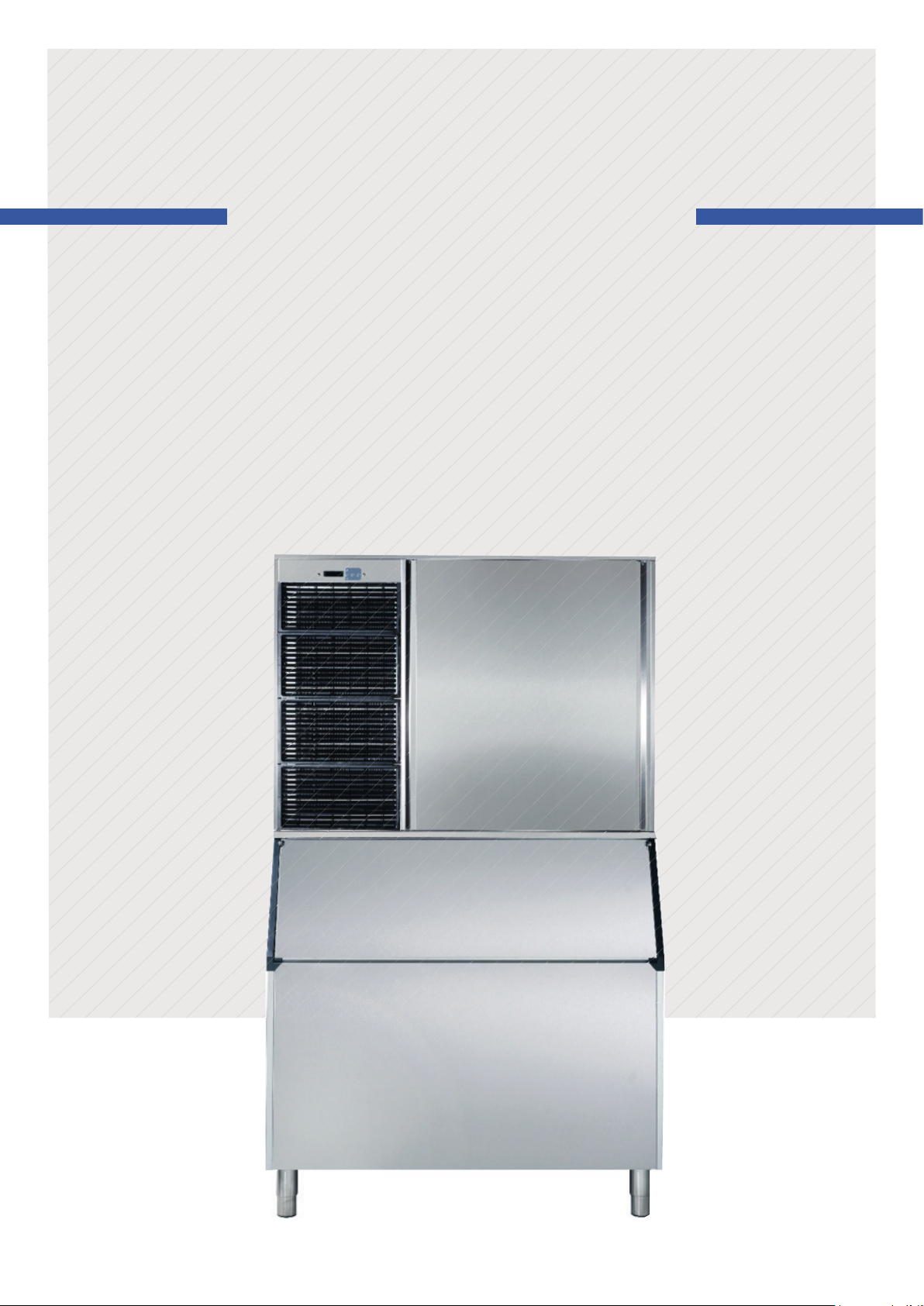
INSTRUCTIONS MANUAL
Sold separated
Page 2

HOW TO USE THIS MANUAL CORRECTLY
DESCRIPTION OF THE CONTENT
This manual has been created to provide the installation technician with information for the
machine’s correct installation and effective maintenance.
The document also contains a section that describes the cause of potential incidents as well as
detailed information for resolving them.
This manual should be stored in a safe place so it may be used to resolve matters related to
the machine’s operation throughout its service life.
RECEPTION AND INSTALLATION
The installation technician who handles the reception and installation may refer to the first
part of this document for important information on how to properly connect the machine to
the mains, water mains and drainage, as well as the conditioning factors and limitations. This
manual also contains comprehensive information about installing multiple stacked devices.
OPERATION
This document has been prepared so anyone may easily understand the machine’s operating
principles and quickly view each status. The manual also serves as a valuable guide about the
menus and explains in detail each of the messages that appear on the display in a technical
annex located at the end.
SPECIFICATIONS AND ADJUSTMENTS
The manual’s user can consult technical information regarding the machine’s parameters,
production ranges, pressostat adjustments, electrical or water consumption, and refrigerant
charges.
MAINTENANCE AND CLEANING
In order for this document to serve as a comprehensive guide for the installer, a section has
been included with periodic maintenance and cleaning instructions as well as a detailed
explanation of how to clean each element. It is essential to refer to this manual in order to
guarantee the machine’s optimal service life.
INCIDENT RESOLUTION
The document includes a technical support table to help users resolve common issues. It
serves as a guide for diagnosing issues and provides the most probable solutions.
QUALITY PARAMETERS AND CUSTOMER SERVICE
This machine has been manufactured according to rigorous quality standards. If any incidents
arise, please contact the company that installed the machine or the Customer Service
department of the manufacturer:
P.I. Sector 13. Avda. dels Hostalers, 2
46394 Ribarroja del Turia. Valencia. Spain
0034961667639/ Hours: 8:00 a.m. to 7:00 p.m.
Page 3

INDEX
1. INTRODUCCIÓN----------------------------------------------------------------------------------------------------1
• 1.1 Warnings ----------------------------------------------------------------------------------------------1
• 1.2 Description---------------------------------------------------------------------------------------------1
2. RECEPTION OF THE MACHINE ---------------------------------------------------------------------------------2
3. INSTALLATION------------------------------------------------------------------------------------------------------2
• 3.1 Conditions of the location--------------------------------------------------------------------------2
• 3.2 Water and drainage connetions-------------------------------------------------------------------2
• 3.3 Connection to the water main---------------------------------------------------------------------3
• 3.4 Connection to the drain-----------------------------------------------------------------------------3
• 3.5 Electrical connection---------------------------------------------------------------------------------3
• 3.6 Stacking kit---------------------------------------------------------------------------------------------4
3.6.1 Machine stacking-----------------------------------------------------------------------------------5
• 3.7 Thermostat connections----------------------------------------------------------------------------8
• 3.8 Remoter condenser unit----------------------------------------------------------------------------9
4. START UP----------------------------------------------------------------------------------------------------------10
5. OPERATION-------------------------------------------------------------------------------------------------------11
• 5.1 Operation principle---------------------------------------------------------------------------------11
• 5.2 Display-------------------------------------------------------------------------------------------------12
5.2.1 Machine operations states--------------------------------------------------------------------12
5.2.3 Menús ----------------------------------------------------------------------------------------------14
• 5.3 Parameterisation------------------------------------------------------------------------------------16
6. SPACIFICATIONS-------------------------------------------------------------------------------------------------17
• 6.1 Production table------------------------------------------------------------------------------------17
• 6.2 Power consumption, water consumption and refrigerant charge----------------------18
• 6.3 Weights & dimensions-----------------------------------------------------------------------------18
• 6.4 Water and drainage connections----------------------------------------------------------------19
7. REGULATIONS----------------------------------------------------------------------------------------------------20
• 7.1 Pressure switch of the condenser water valve (Water condensation)-----------------20
• 7.2 Fan pressure switch (Air-condensed machines)---------------------------------------------20
• 7.3 Safety pressure switch-----------------------------------------------------------------------------20
Page 4

8. MAINTENANCE AND CLEANING INSTRUCTIONS AND PROCEDURES-------------------------------21
• 8.1 Water condenser------------------------------------------------------------------------------------22
• 8.2 Aire condenser---------------------------------------------------------------------------------------22
• 8.3 Evaporator/ Water container--------------------------------------------------------------------22
8.3.1 Cleaning instructions-----------------------------------------------------------------------------22
• 8.4 Collector and injectors-----------------------------------------------------------------------------23
• 8.5 Cleaning the inlet filters---------------------------------------------------------------------------24
• 8.6 Control of water leaks------------------------------------------------------------------------------24
9. CONSIDERATIONS REGARDINGS USE OF THE R404 REFRIGERANT----------------------------------24
10. ALARMS----------------------------------------------------------------------------------------------------------24
• 10.1 Full Stock--------------------------------------------------------------------------------------------24
• 10.2 Cycle probe------------------------------------------------------------------------------------------25
• 10.3 Aire temperatura probe--------------------------------------------------------------------------25
• 10.4 High pressure---------------------------------------------------------------------------------------25
• 10.5 Long pre-heating-----------------------------------------------------------------------------------25
• 10.6 Long pre-cooling-----------------------------------------------------------------------------------25
• 10.7 Short pre-cooling----------------------------------------------------------------------------------25
11. TABLE OF INCIDENTS------------------------------------------------------------------------------------------26
12. TECHNICAL ANEX-----------------------------------------------------------------------------------------------29
WIRING DIAGRAMS: AT THE END OF THE MANUAL
Page 5

1. INTRODUCTION
1.1 WARNINGS
This device must be installed by a specialist technician.
Any modification necessary to the electrical installation for the perfect connection of the machine must
be carried out exclusively by professionally qualified and authorised staff.
To guarantee the efficient and correct operation of this device, it is essential to follow the manufacturer's
instructions, particularly with regard to maintenance and cleaning operations, which in most cases should
be carried out by qualified staff.
Actions by unqualified persons, apart from being dangerous, can cause serious faults. In case of a fault,
contact the distributor who sold it to you. We recommend that you always demand original spare parts.
Any use of the ice-cube-maker other than for producing ice, using drinking water, is considered
inappropriate.
Modifying or attempting to modify this device, apart from voiding the warranty, is extremely dangerous.
The machine should not be used in the open air or exposed to the rain. Connect to the drinking water
mains.
The machine should be connected using the cable supplied. It is not designed to be connected to a fixed
pipe.
Always disconnect the machine from the mains before carrying out any cleaning or maintenance work.
The electrical base must be in an accessible place.
We recommend the use of filtration in case of low water quality.
Carry out unloading and recovery of materials or waste according to your national regulations on the
matter.
This device can be used by children older than 8 years and persons with impaired physical, sensory or
mental capacities, or who lack experience or knowledge, if they have had supervision or instruction in the
use of the device from a person responsible for their safety. Children should be supervised to ensure that
they do not play with the device. Children cannot do the cleaning and maintenance of the device without
supervision.
Do not store explosive substances such as cans of aerosol with flammable propellant in this device.
1.2 DESCRIPTION
The most important features are:
Modular machine.
Display with LDC screen of 16x2 characters.
Cleaning system included in the electronic programmer.
AISI 304 stainless steel chassis
Anti-jamming injectors installed in 3 rotating collectors.
Pumps without seals (2)
High/low pressure safety gauge.
Tropical-temperature machine. Ready to work up to 43ºC.
TRANSPARENT CUBES with mostly mains water.
1
Page 6
2. RECEPTION OF THE MACHINE
Inspect the exterior of the packaging. If it is broken or damaged, complain to the haulier.
To checky whether the machine is damaged, UNPACK IT IN THE PRESENCE OF THE HAULIER and make a record on
the reception document, or on a separate document, of any damage that the machine may have suffered. Since 1
May 1998, it has complied with European regulations on the management
of Packaging and Packaging Waste.
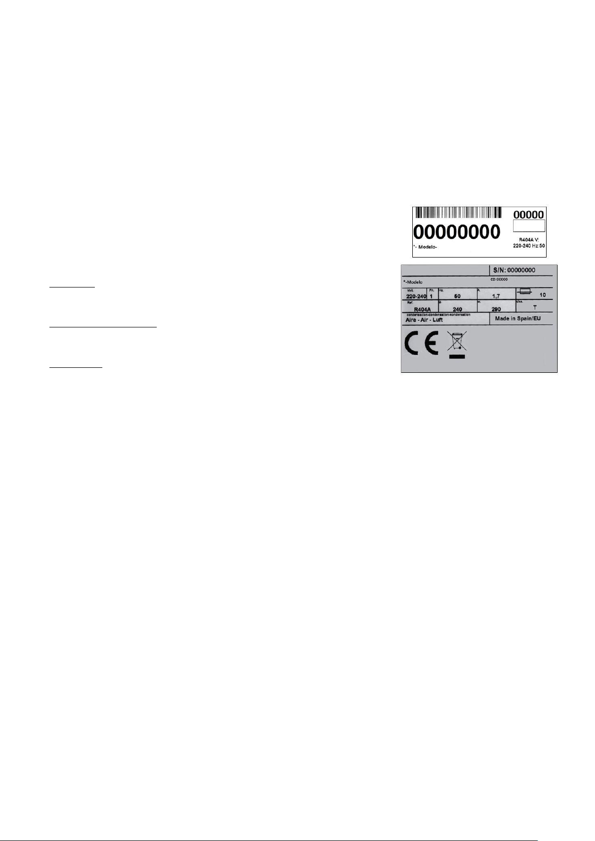
Always record the machine and model number. This number is marked in
three places:
Packaging
There is an external label with the factory number.
Exterior of the machine
On the back, on a label that is identical to the front.
Name plate
Check that the installation kit is complete inside the machine. It is consists of: ¾ gas connection, two filter joints,
anchor bolts and the manual.
CAUTION: THE PACKAGING ITEMS (PLASTIC BAGS, CARDBOARD BOXES AND WOODEN PALLETS) MUST NOT BE
LEFT WITHIN REACH OF CHILDREN AS THEY ARE A POTENTIAL SOURCE OF DANGER
3. INSTALLATION
3.1 CONDITIONS OF THE LOCATION
The machines are designed to function in an ambient temperature of between 5ºC and 43ºC, and with water
input temperatures of between 5ºC and 35ºC.
Below these minimum temperatures, there may be difficulty in removing the cubes. Above the maximum, the life
of the compressor is shortened and production is considerably reduced.
3.2 WATER AND DRAINAGE CONNECTION
Bear in mind the following preliminary considerations on water quality:
Water quality has a significant influence on the quality, hardness and taste of the ice, and on the life of the
condenser in water-condensed machines.
a) Water impurities: larger impurities are retained by the filters which come with each machine. The filters must
2
Page 7

be cleaned according to the purity of the water. For small impurities, we recommend the installation of a 5
micron filter.
b) Hard water: the ice will be less compact and the cubes may stick to each other. Some cubes may appear with
white marks. Inside the machine, lime deposits will form, which may interfere with its proper functioning. Water
condensate may obstruct the condenser or reduce its performance. To avoid incrustations it is advisable to install
a water filtering system. We recommend the use of a polyphosphate filter.
c) Highly-chlorinated water: the ice may taste of bleach (chlorine). In order to eliminate this taste, you can install
an activated carbon filter.
Bear in mind that you may receive water which is simultaneously affected by these three problems.
d) High purity water: production may be reduced by up to 10%.
3.3 CONNECTION TO THE WATER MAINS
Use the flexible connection (length 1.3 m.) with the two filter joints supplied with the machine. We do not advise the use of
double outlet taps with two stopcocks as they may close the rear one by mistake, leaving the machine without water. Water
pressure must be between 1 Bar and 6 Bar. If the pressure exceeds these values, install the necessary corrective components.
It is important that the water line does not pass close to sources of heat, and that the flexible hose or the filter does not
receive hot air from the machine. Otherwise this would cause production to decrease as the water would be heated.
3.4 CONNECTION TO THE DRAIN
The drain must be below the machine, by at least 150 mm.
In order to prevent bad smells, install a siphon. The drainage pipe should ideally have an internal diameter of 60 mm. and a
minimum slope of 3 cm per metre.
3.5 ELECTRICAL CONNECTION
The machine is supplied with a 1.5 metre cable. If the power cable is damaged, it must be replaced with a special
cable or set supplied by the manufacturer or the after-sales service.
The machine should be positioned in such a way that a minimum space is left between the back of the machine and the wall
so the plug on the end of the cable can be plugged in comfortably and without any risk.
Supply a suitable socket.
It is a good idea to install a switch and suitable fuses. The voltage and intensity are marked on the name plate and in the
technical pages of this manual. Voltage variations of more than 10% above that indicated on the plate may cause
breakdowns or prevent the machine starting.
The line to the socket must have a minimum cross-section of 2.5 mm2.
Check that the mains voltage and that indicated on the name plate are the same.
IMPORTANT: Ensure that there is a proper earth connection when connecting the machine. Consult the current legislation or
the regulations of the country where it is installed.
The electronic board has a button battery to maintain the time. In the installation, please remove the plastic protecting the
battery (board in the upper side, behind the display, remove two screws under the upper air grille, to access the electric box).
3
Page 8

Reference
Description
Units
Comments
8141
STACKING OUTLET
1
Outlet assembly (Detail B)
8823
ASSEMBLY OF STACKING RAMP-PLATE
1
Ice cube ramp assembly
3x1 mm2 interconnecting hose for machines
8824
STACKING RAMP TEMPLATE
1
Ice cube ramp assembly
3x1 mm2 interconnecting hose for machines
8145
STACKING WIRING KIT
1
Ice cube ramp assembly
3x1 mm2 interconnecting hose for machines
2452
DIN 127 M-8 ZINC GROVER WASHER
4
Stacking of machines (Detail A)
2515
DIN 9021 M-8X23 ZINC WASHER
4
Stacking of machines (Detail A)
8142
STACKING SPACER
4
Stacking of machines (Detail A)
285
DIN 934 M-8 ZINC NUT
4
Stacking of machines (Detail A)
722
DIN 912 M-8X50 ZINC SCREW
4
Stacking of machines (Detail A)
244
DIN 7981 2.9X9.5 STAINLESS STEEL SCREW
2
Outlet assembly (Detail B)
302
4X10 STAINLESS STEEL RIVET
3
Stacking of machines (Detail A)
3.6 STACKING KIT
In case of stacking 2 machines, a stacking kit is supplied, made up of the following parts:
To stack two machines, you need to make some modifications to the electrical connections of the machine. Carry
out the stacking before making the electrical installation. In addition, the stock thermostat connections have to be
changed in both machines.
NOTE: Use a drill no longer than 20 mm to avoid damaging the bin.
4
Page 9
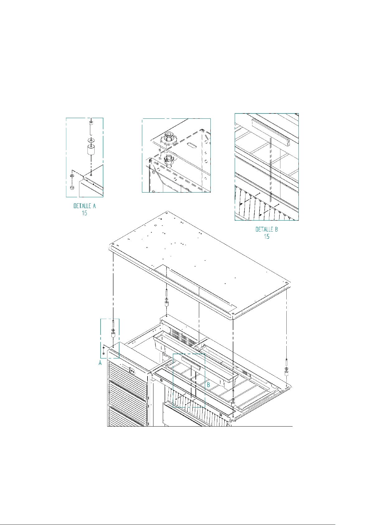
3.6.1 MACHINE STACKING
To carry out the stacking, remove the top panel of the machine that is going to be placed below and the front panel
as shown in the illustration.
Once the top and front panels are removed, install the kit as shown in details A and B. To install the outlet, remove
the plate that covers the ice outlet (remove fasteners and file the perimeter).
5
Page 10
MACHINE STACKING: DIAGRAM
6
Page 11
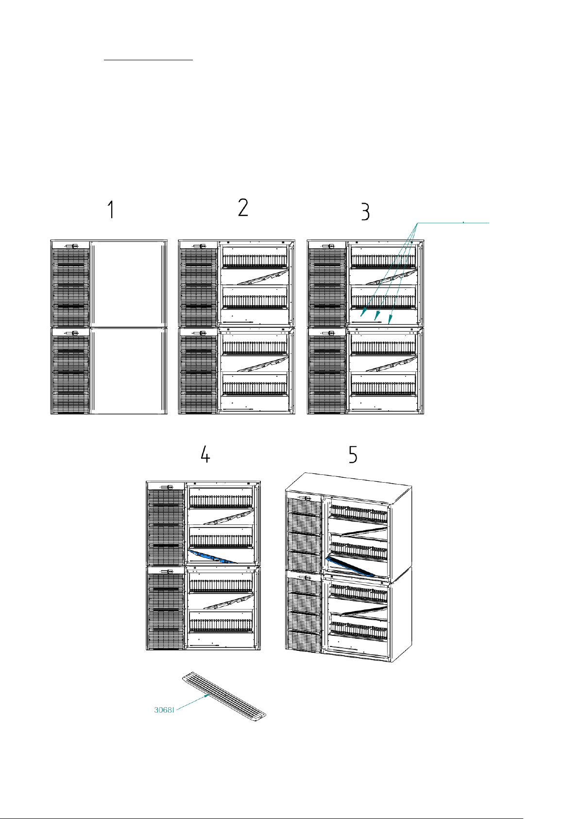
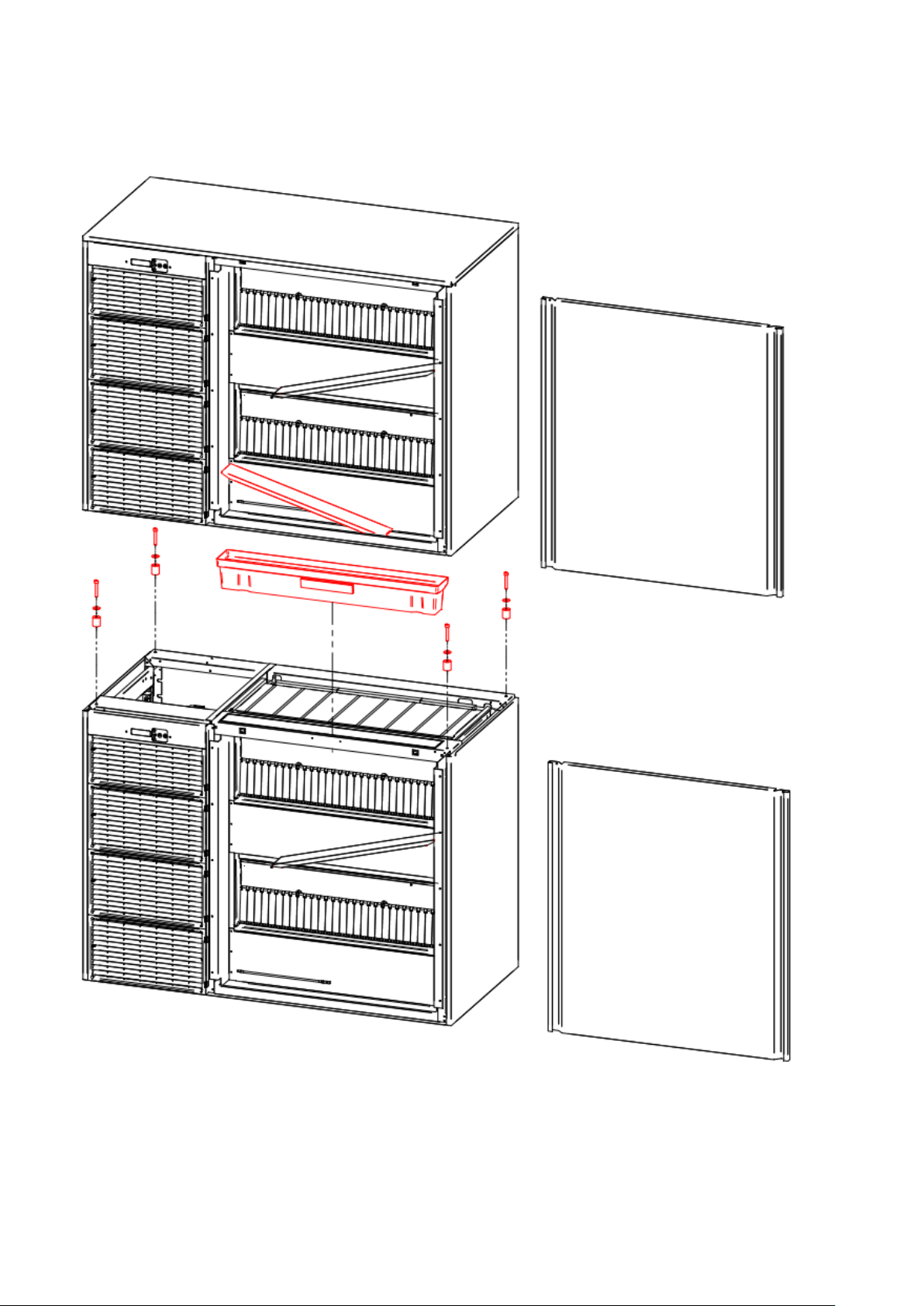
Remove caps
The steps to assemble the ramps are shown below:
1. The two machines should already be stacked.
2. Remove both front covers.
3. Remove the three plastic caps from the riveted nuts to be able to screw.
4. Place the ramp 30681 and screw it, as shown in the image.
5. Final position of the ramps.
7
Page 12

3.7 THERMOSTAT CONNECTIONS
Machine stacking kit
8
Page 13
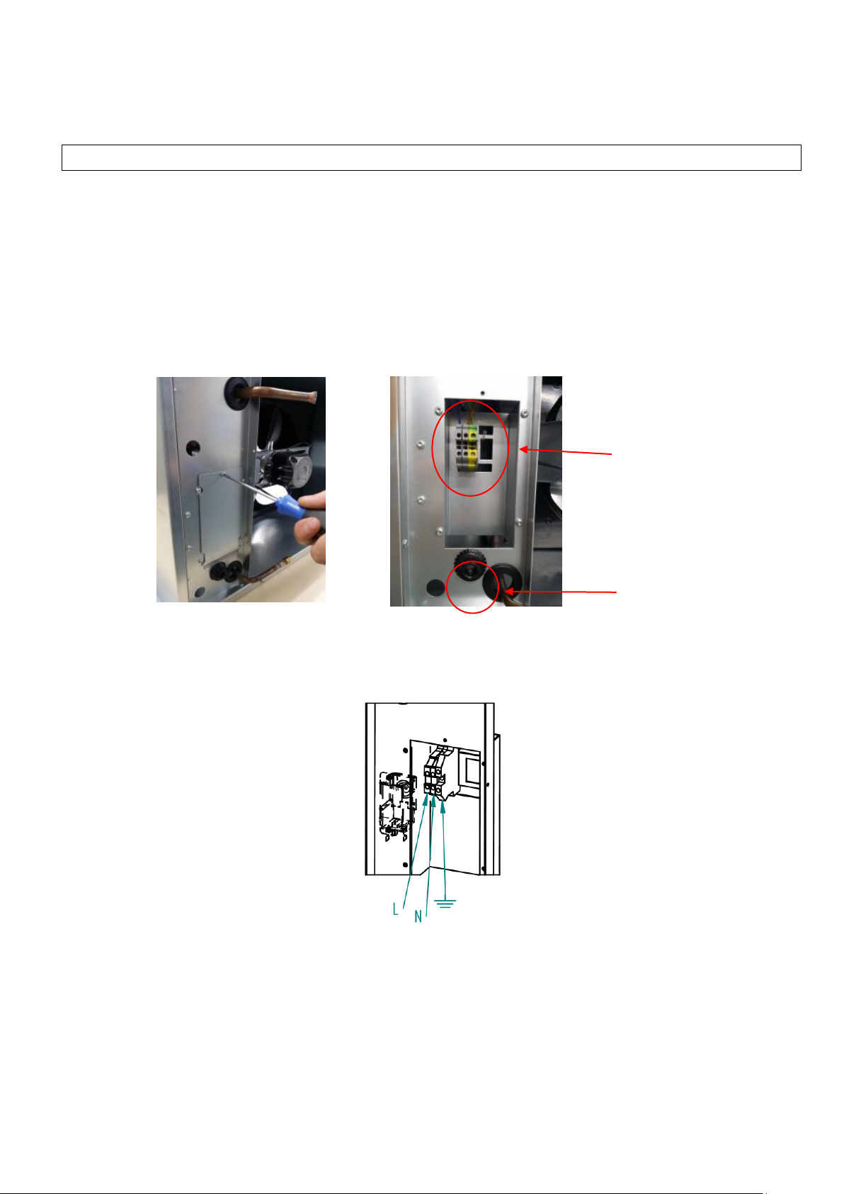
Terminal connector
Cable passing
hole
3.8 REMOTE CONDENSER UNIT
If you have purchased a machine with a remote condenser, follow the instructions for its installation.
STEP 1: PLACING BOTH UNITS (REMOTE CONDENSER AND SPLIT MACHINE) IN ITS LOCATION
CHECKING THE PROPER CONNECTIONS FOR EACH UNIT:
REMOTE CONDENSER:
The condenser includes the condenser pressure switch
It needs an electrical supply (check label with power supply specifications). It comes without an electrical
cable. Connect to the power supply directly (it does not need communication with the split unit).
To connect, remove the rear cover, using a Torx screwdriver. The electrical cable must go through the
hole next to the piping hole. Use a 3x1.5 mm2 electrical cable.
Terminal connector to supply electrical power to the remote condenser, located behind the metallic cover.
Level the unit correctly.
Locate the remote condenser unit under a shadow. We advise to place it under a roof, whenever possible.
The remote condenser unit works between 0ºC (32ºF) and 43ºC (109.4ºF) air temperature.
9
Page 14
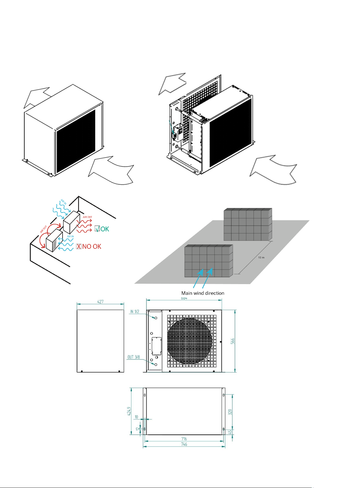
Check the air direction through the remote condenser, always install the unit with the air direction out to
the ambient when installed in a wall, to avoid condensed air returning to the condenser.
If more than one unit is going to be installed, please located them to avoid the condensed air going from
one unit to the other.
10
Page 15
Refrigeration taps
INTERNAL UNIT:
It needs an electrical supply (check label with power supply specifications). The unit comes with an
electric cable, and no plug.
Water supply: it needs a water tap nearby. The unit comes with a water hose, ¾” GAS connection, and
two net filters.
Drain pipe: The unit has two drain pipes. A drainage is need it. The drain pipes must be straight, no
siphons allowed, to let the water drain directly.
Level the unit correctly.
Always check the ice exit, to allow the ice cubes fall free.
In case of stacking two units, please follow the stacking manual.
STEP 2: REFRIGERATION CONNECTION BETWEEN BOTH UNITS
REMOTE CONDENSER: Remove the rear cover if need it.
REMOTE CONDENSER PIPING CONNECTION
Gas pipe: up inlet 1/2”
Liquid pipe: down outlet 3/8”
The remote condenser is sent from factory pressurized. To ensure there is no damage from the transport,
please check that is still pressurized, before cutting the pipes to start the connection.
Always connect the remote condenser to the refrigeration pipes by welding. The remote condenser
comes with the inlet gas pipe closed, and the outlet liquid pipe with a gas intake. Cut both pipes to weld.
11
Page 16

Do the refrigeration installation between the remote condenser and the split unit. Check always that each
tube is in the correct position, and the pipes are not together (to avoid heat exchange between pipes. We
advise to insulate the liquid line.
Try to do a clean installation, as straight forward as possible.
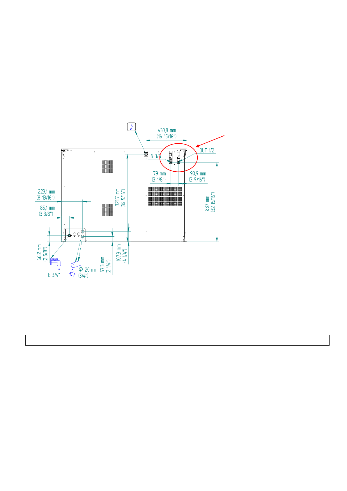
The liquid line must always go from the outlet remote condenser (liquid, lower pipe) to the split unit
liquid inlet (3/8” tap), and the gas inlet from the remote condenser (upper pipe) to the gas outlet in the
split unit (1/2” tap).
If the remote condenser is lower than the split unit, it is necessary to install a siphon in the liquid line,
near the remote condenser, to avoid the oil staying at the condenser.
Do not install the remote condenser lower than 3 meters from the split unit.
If the remote condenser higher or equal to the split unit, a siphon must be installed in the gas line, one
every 4 vertical meters and one every 8 horizontal meters.
SPLIT UNIT: It is connected by a gas tap 3/8” and a liquid gas tap ½”, using the nut that comes with the tap.
STEP 3: INSTALLATION LEAKING TEST AND VACUUM
Once the refrigeration pipes are weld and connected, a leaking test must be done to
check that the line has no leakage in the nuts or the welding.
After checking for leakages, a correct vacuum must be done. We advise to keep vacuum
for around 4 hours.
ATENTION: Do not open the gas taps from the split before doing the vacuum, as the unit comes with
refrigerant.
STEP 4: OPEN GAS AND LIQUID TAPS
Once that everything is correctly installed and there are no leakages, and the vacuum
has been done properly, open the split unit, that comes with a refrigerant charge for 5 meters of distance
between the remote condenser and the split unit. Open slowly the liquid gas tap (3/8”) and then the gas
tap (1/2”).
12
Page 17

STEP 5: ONLY FOR GREATER DISTANCES THAN 5 METERS BETWEEN UNITS
If the distance between the remote condenser and the split is greater than 5 meters, it is
necessary to add some refrigerant. Add 40 grams per extra meter, up to 15 meters maximum.
STEP 6: START UP
Now the split unit can be turn on to try it, and modified the control parameters if need it (electronic
board). Instruccions in the user manual.
NOTE: It is better to use the ambient probe from the split unit to obtain the temperature of the air getting
inside the remote condenser (in the air intake of the condenser). To do so, enlarge the probe cable and put
the probe in the condenser.
13
Page 18

MAXIMUM
MINIMUM
AMBIENT TEMP.
43ºC
5ºC
WATER
35ºC
5ºC
MINIMUM
1 Bar / 0.1 MPa
MAXIMUM
6 Bar / 0.6 MPa
4. START UP
4.1 PRIOR CHECK
Is the machine level?
Are the voltage and frequency as indicated on the plate?
Are the drains connected and do they work?
Is it connected to cold water?
** If the machine is air condensed, are the air circulation and the temperature of the premises right?
Is the water pressure correct?
NOTE: If the incoming water pressure is greater than 6 Bar, install a pressure reducer.
CAUTION: CHECK THAT THE VOLTAGE AND FREQUENCY OF THE MAINS ARE THE SAME AS THOSE INDICATED ON
THE NAME PLATE.
4.2 START UP
After following the installation instructions (ventilation, conditions of the premises, temperatures, water quality,
etc.), proceed as follows:
1. Open the tap to let water flow. Check that there are no leaks.
2. Connect the machine to the mains with its corresponding protection.
3. Activate the button on the display installed on the front of the machine.
4. Check that there is no part which is rubbing or vibrating.
5. Check that the curtain can move freely.
6. Check that the injectors send the water to the evaporator in the correct direction.
7. Check that the collectors turn freely on their axles.
8. Once 10 minutes have passed, check that the water container has no leaks through the maximum level overflow
channel.
Note: The electronic plate has a battery to keep the date and time. The battery is protected with a plastic to
prevent their consumption. The first time using the unit, remove the plastic (opening the upper compartment,
display area, access to the electronic board box and inside is the battery with plastic).
14
Page 19
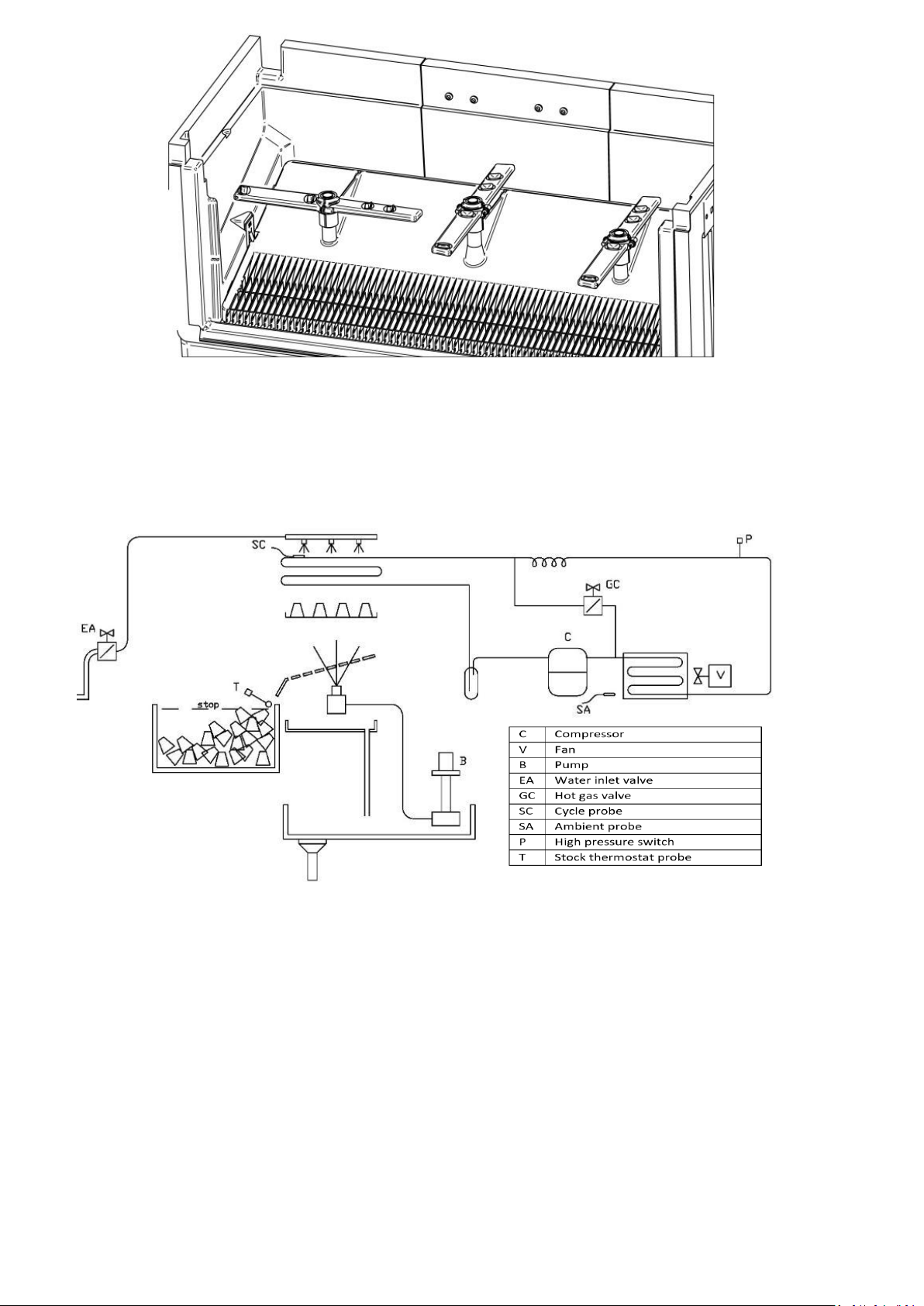
5. OPERATION
5.1 OPERATING PRINCIPLE
1. When the start button is pressed, the machine begins with a starting timed period, during which the water inlet
electro-valve (EA) is opened.
2. After this timed start, the working cycle begins:
3. It starts with the detachment operation.
4. When the detachment time begins, the hot gas electro-valves (GC) and the water inlet electro-valves (EA)
remain open, and the compressor and fan start up. The water pump runs for 30 seconds to help detachment.
5. When detachment is complete, ice-making begins.
6. The compressor (C) and the fan (V) continue to work, the pump (B) starts and the hot gas valves (GC) and water
inlet valves (EA) close.
7. From this moment on, the evaporator begins to cool during the production time.
8. Once the production time has finished, the detachment process will begin again.
15
Page 20
Starting…
Harvest
9. Each entire cycle is considered to begin when the production time starts and ends when the
detachment time has finished, at which point a new production cycle begins.
*The hot gas electro-valve GC has to open during 5 seconds before the compressor starts. The remaining
components are stopped, including the compressor.
*Expansion controlled by expansion valve.
5.2 DISPLAY
5.2.1 MACHINE OPERATING STATES
Machine off
The time is shown on the display when the machine is off (no light). When the machine is disconnected from the
power supply the time is lost. When reconnected it starts at 00:00, flashing to indicate that the time is not set.
Start
When the machine is working during the start time, the display will appear as follows:
Detachment
When the machine is working during the detachment time, the display will appear as follows:
At the bottom of the screen it will show the temperature indicated by the SC cycle probe.
16
Page 21
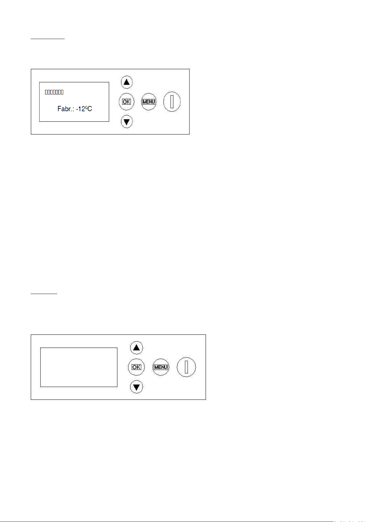
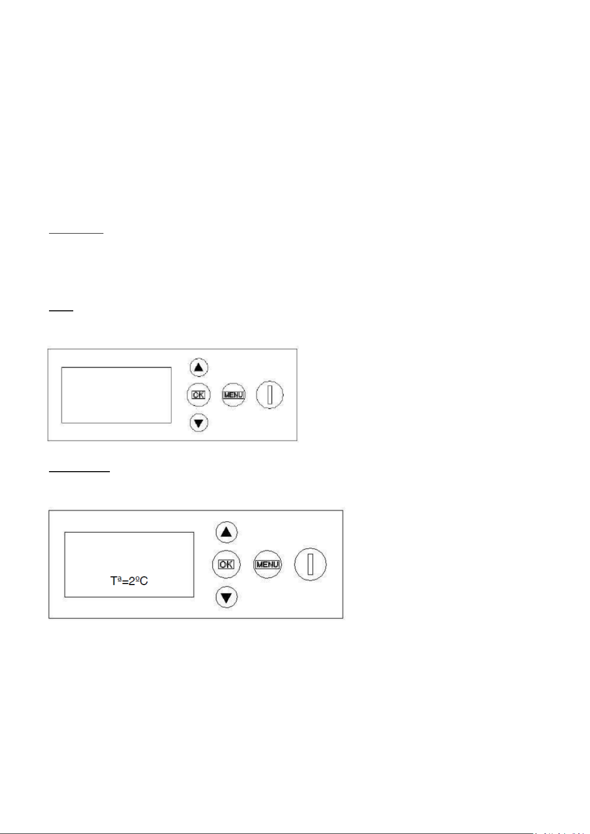
Washing
Production
When the machine is working during the production time, the display will appear as follows:
When the detachment has finished the screen will show a progress bar with the time remaining until the end of
the cycle.
It will also show the following text at the bottom of the screen: “Fabr.: -12ºC”, with the temperature indicated by
the SC cycle probe.
As the production time is “tf=tfv+tff” and at the start it is not known how long the “tfv” will last, since it depends
on the “Tfc”, take as a reference: cooling time “tfv” of the last cycle + set production time “tff”.
If the tfv of the last cycle is not known, use a time of 25 minutes (total production time tf=tfv+tff) for the
calculation (for example, in the first cycle of the machine).
Once the cycle has started and, as soon as point 4 on the graph is reached, you will know exactly the time
remaining until the end of the cycle, because "tf" will be defined at that time. Therefore, at this point, the bar will
be recalculated so that it reaches the end just as the cycle has finished.
Cleaning
Only the water pump works. It can be accessed with the machine off, pressing simultaneously the “OK” and
power “I” buttons for 3 seconds.
The display will show:
To end the cleaning cycle, press the power button “I” and the machine will turn off.
17
Page 22

Defrost
Defrost
After reaching the “tMmax” and the pump is operating, the screen will display the message “Defrost”
and will show the progress bar for the set defrost pump time “tBdesescarche”.
5.2.3 MENUS
The parameters of the machine can be adjusted, as required, on the display menu. The machine has 3
menus:
Main menu: this menu is accessed by pressing the "Menu" button while the machine is Off.
“Time setting” time setting. Locate on the menu, press the buttons to make the correct adjustment.
After selecting the time, press “OK” and set the minutes. By pressing “OK” again, the time will be set and you
will return to the menu.
“Programmer” programmer. This option allows you to programme the start and stop time of the machine.
Look for the “Programmer” option in the menu. By pressing the button the “Activate” option will appear.
After selecting the “Activate” option, the fields to complete, “Start” and “End”, will appear on the screen.
“Language” language. After locating the menu with the buttons select the language and press “OK”.
“Exit” exit.
Information menu: you can access this menu at any time while the machine is working or with the
machine off by pressing the “MENU” button for 3 seconds: This menu provides access to:
Ambient probe temperature “Amb.T”
Cycle probe temperature “Cyc.T”
Last cycle production time “Freez.t”
Last cycle complete time “Cyc.t”
Instant production time of current cycle “Cur.F.t”
Remaining production time of current cycle “rem.F.t”
Instant detachment time of current cycle “cur.H.t”
Remaining detachment time of current cycle “rem.F.t”
18
Page 23

Status of inputs “On/off” “I1234”
Status of outputs “On/off” “O1234”
Cycle counter
Exit
Configuration menu: you can access it by pressing simultaneously for 3 seconds.
You can access at any moment of operation or with the machine switched off.
Set production time “Freezing Time”
Setpoint production temperature “Freezing Temp”
Set detachment temperature “Harvest time”
Setpoint detachment temperature “Harvest Temp”
Water inlet time “water time”
Pump time during initial detachment “in.pump harv.t.”
Pump time during final detachment “fin.pump harv.t.”
Balance time (hot gas) during start-up “balancing time”
Start time “start t.”
Minimum downtime due to full stock “min stock t”
Minimum downtime due to safety switch “min.security t”
Maximum variable detachment time “max. harvest t”
Maximum variable production time “max. Freez. t”
Minimum variable production time “min. Freez. t.”
Maximum machine time “max. machine t”
Defrost pump time “defrost pump t”
By default “standard values”
Exit
19
Page 24

Parameter
Description
Electronic
board
factory
settings
Minimum
value
Maximum
value
23/30 cc
65/68 cc
36/40 cc
48/52 cc
start t
Initial start time of machine
after disconnection (open
water inlet)
02’00’’
00’00’’
02’00’’
02’00’’
balancing time
Hot gas valve opening time for
balancing pressures before
activating the compressor
during start-up. DO NOT
CHANGE
00’05’’
00’00’’
01’00’’
00’05’’
Harvest Temp
Setpoint detachment temp.
0 ºC
-50°C
+20°C
0°C
Harvest time
Detachment time after
obtaining “Harvest Temp.”.
02’00’’
00’00’’
05’00’’
00’50’’
02’00’’
01’00’’
02’00’’
Freezing Temp
Production setpoint temp.
-10°C
-50°C
+20°C
-10°C
Freezing Time
Production time after obtaining
“Harvest Temp.”.
22’00’’
00’00’’
60’00’’
12’00’’
22’00’’
14’00’’
20’00’’
water time
Water time after obtaining
“Harvest Temp.”.
02’00’’
00’00’’
10’00’’
00’40’’
01’50’’
00’50’’
01’50’’
min stock t
Minimum machine downtime
due to full stock. DO NOT
CHANGE
02’00’’
00’00’’
10’00’’
02’00’’
min.security t
Minimum machine downtime
due to safety switch. DO NOT
CHANGE
60’00’’
00’00’’
99’00’’
60’00’’
max. harvest t
Maximum detachment time to
raise an alarm if the
temperature does not
exceed “Harvest Temp.” DO
NOT CHANGE
05’00’’
00’00’’
30’00’’
05’00’’
max. Freez. t
Maximum production time to
raise an alarm if the
temperature is not less
than “Freezing Temp”. DO NOT
CHANGE
60’00’’
00’00’’
99’00’’
60’00’’
min. Freez. t
Minimum production time to
raise an alarm if the
temperature is less
than “Freezing Temp”. DO NOT
CHANGE
02’00’’
00’00’’
10’00’’
02’00’’
in.pump harv.t.
Pump activation time after start
of detachment.
00’30’’
00’00’’
02’00’’
00’30’’
00’40’’
00’30’’
00’40’’
fin.pump harv.t
Pump activation time before
end of detachment.
00’00’’
00’00’’
05’00’’
00’00’’
max. machine
Activates the defrost.
Maximum cont. operation time
of the machine without
disconnections or downtime.
00h00’
00h00’
96h0’
00h00’
defrost pump t
Active pump time for defrost.
30’00’’
07’00’’
60’00’’
30’00’’
5.3 PARAMETERISATION
20
Page 25

PRODUCTION TABLE 220/50
WATER °C
AIR °C
10
15
21
30 10
361
349
334
319 20
356
345
328
312 32
340
326
312
296 43
261
242
231
204
PRODUCTION TABLE 400/50 A/W
WATER °C
AIR °C
10
15
21
30 10
397
389
378
350 20
390
381
373
345 32
365
356
349
315 43
315
303
294
260
PRODUCTION TABLE 220/60/3N AIR
WATER °C
AIR °C
10
15
21
30 10
371
365
360
353 20
365
361
352
343 32
339
330
318
310
43
275
260
250
235
PRODUCTION TABLE 400/50 REMOTA AIR
WATER °C
AIR °C
10
15
21
30 10
378
375
350
322 20
375
373
345
320 32
350
340
310
290 43
330
320
285
260
6. SPECIFICATIONS
6.1 PRODUCTION TABLE
25gr
25gr
25gr
25gr
21
Page 26

PRODUCTION TABLE 220/50 AIR
WATER °C
AIR °C
10
15
21
30 10
387
375
359
342
20
382
370
352
335
32
365
350
335
318
43
280
260
248
219
PRODUCTION TABLE 220/50 WATER
WATER °C
AIR °C
10
15
21
30 10
383
371
355
339
20
378
366
349
332
32
361
347
332
315
43
277
257
246
217
PRODUCTION TABLE 400/50 AIR
WATER °C
AIR °C
10
15
21
30 10
430
420
390
350
20
418
409
373
345
32
395
384
345
315
43
350
340
300
260
PRODUCTION TABLE 220/50 WATER
WATER °C
AIR °C
10
15
21
30 10
430
415
400
350
20
420
405
380
338
32
400
380
360
315
43
380
360
334
290
36gr
36gr
36gr
36gr
22
Page 27

PRODUCTION TABLE 400/50 REMOTA AIR
WATER °C
AIR °C
10
15
21
30 10
406
403
376
346
20
403
400
370
344
32
376
365
333
311
43
354
344
306
279
PRODUCTION TABLE 220/50 AIR
WATER °C
AIR °C
10
15
21
30 10
378
367
351
334 20
374
362
344
328 32
357
342
328
311 43
274
254
243
214
PRODUCTION TABLE 220/50 WATER
WATER °C
AIR °C
10
15
21
30 10
378
366
350
334 20
373
361
343
327 32
356
341
327
310 43
273
254
242
214
PRODUCTION TABLE 220/50 AIR
WATER °C
AIR °C
10
15
21
30 10
369
358
342
326 20
364
353
336
319 32
348
334
319
303 43
267
248
236
209
36gr
51gr
51gr
62gr
23
Page 28

PRODUCTION TABLE 220/50 WATER
WATER °C
AIR °C
10
15
21
30 10
368
357
341
325 20
363
352
335
319 32
347
333
319
302 43
266
247
236
208
PRODUCTION TABLE 400/50 AIR
WATER °C
AIR °C
10
15
21
30 10
405
391
385
360 20
400
391
380
355 32
387
378
370
342 43
330
320
307
280
PRODUCTION TABLE 400/50 WATER
WATER °C
AIR °C
10
15
21
30 10
405
394
385
360 20
400
391
380
355 32
390
382
373
345 43
350
330
315
300
PRODUCTION TABLE 400/50 REMOTA AIR
WATER °C
AIR °C
10
15
21
30 10
387
384
358
330 20
384
382
353
328 32
358
348
317
297 43
338
328
292
266
62gr
62gr
62gr
62gr
Data obtained with amb. temp.=20°C, water inlet temp.=15°C and water quality=500ppm
Maximum consumption obtained at ambient temperature = 43ºC, according to UNE standards for climate classification Class T (TROPICAL).
The ice production will vary with the water quality, decreasing with water quality below or above 500 ppm.
24
Page 29

6.2 POWER CONSUMPTION, WATER CONSUMPTION AND REFRIGERANT CHARGE
MODEL
COMPRESSOR
POWER HP
ABS POWER
W
TOTAL
INTENSITY
(A)
400 A
(380 / 50-60Hz) III
5
3500
6.5
400 REMOTE
5
3500
6.5
400 A
(230 / 60Hz)
III
5
3500
10.7
MODEL
TOTAL CONSUMPTION L/H
400 A
27
400 W
217
MODEL
NET WEIGHT
GROSS
WEIGHT
MACHINE
DIMENSIONS
PACKAGING
DIMENSIONS
400
165 (A)
166 (W)
191
1321x638x978
1410x740x1115
400A remota
158
178
1321x638x978
1410x740x1115
6.3 WEIGHTS & DIMENSIONS
25
Page 30

ICE CHUTE
6.4 WATER AND DRAINAGE CONNECTIONS
26
Page 31

7. REGULATIONS
7.1 CONDENSER WATER VALVE PRESSURE SWITCH (WATER CONDENSATION)
The pressure switch controls high pressure by opening and closing the condenser water valve. The differential is
fixed at 1 bar (14 psi).
The closed pressure should be 15 bar (214 psi), equivalent to an output temperature of the condensation water
of 38º C. Below this pressure, there may be difficulties in detaching the cubes.
Above this pressure, the life of the compressor is shortened and ice production decreases.
Pressure is increased by turning the adjusting screw clockwise. One turn is approximately equivalent to 1.5 Bar.
7.2 FAN PRESSURE SWITCH (AIR-CONDENSED MACHINES)
The pressure switch controls the pressure through stopping and starting the fan. The differential is fixed at 1 bar
(14 psi).
The stopping pressure should be 15 bar (214 psi). Below this pressure, there may be difficulty in removing the
cubes.
Above this pressure, the life of the compressor is shortened and ice production decreases.
Pressure is increased by turning the adjusting screw clockwise. One turn is approximately equivalent to 1.5 Bar.
7.3 SAFETY PRESSURE SWITCH
The safety pressure switch has the function of ensuring safety from excessive discharge pressure, which may be
due to:
A dirty condenser, poor air circulation or very high room temperature (air condensation).
Lack of water or very high water temperature (water condensation).
The high pressure parameters are fixed
Disconnection: 30 Bar.
Connection: 22 Bar.
27
Page 32

ACTION
MONTHLY
QUARTERLY
BIANNUAL
ANNUAL
BIENNIAL
T UNIT
Air condenser cleaning
30 minutes
Water condenser
cleaning
90 minutes
Injector cleaning
30 minutes
Production water
circuit cleaning
45 minutes
Sanitary cleaning
30 minutes
Water filter
cleaning/replacement
30 minutes
Exterior cleaning
Essential
Depending on the conditions of the premises
Depending on the conditions and water quality.
To be performed by the user
8. MAINTENANCE AND CLEANING INSTRUCTIONS AND PROCEDURES
CAUTION: MAINTENANCE AND CLEANING OPERATIONS, AND ANY MALFUNCTIONS CAUSED BY THEIR
OMISSION, ARE NOT INCLUDED IN THE WARRANTY.
The machine will only continue to produce good-quality ice free of malfunctions if maintenance is properly
performed.
Maintenance and cleaning intervals depend on the conditions of the premises where the machine is installed and
the water quality.
Checking and cleaning should be carried out at least every six months.
In very dusty places, it may be necessary to clean the condenser in air-condensed machines every month.
MAINTENANCE TABLE
CAUTION: FOR ALL CLEANING AND MAINTENANCE OPERATIONS, DISCONNECT THE MACHINE FROM THE
POWER SUPPLY.
28
Page 33

1
8.1 WATER CONDENSER
1) Disconnect the machine.
2) Disconnect the water inlet or close the tap.
3) Disconnect the water inlet and outlet from the condenser.
4) Prepare a 50% solution of phosphoric acid and distilled or demineralised water (or a suitable product to clean
the water condenser circuit).
5) Make it circulate through the condenser. (The mixture is more effective when hot - between 35º and 40º C-)
Do not use hydrochloric acid.
8.2 AIR CONDENSER
1) Disconnect the machine.
2) Disconnect the water inlet or close the tap.
3) Clean with the help of a vacuum cleaner, non-metallic brush or low-pressure air.
8.3 EVAPORATOR / WATER CONTAINER
8.3.1 CLEANING INSTRUCTIONS
1. We recommend using the cleaning product Calklin. Prepare a solution with 50% phosphoric acid and distilled
water. Do not use hydrochloric acid. Remove the rear panel to access the production containers. Remove the
cover attached to the pump to access the interior of the container where you should pour the previously
prepared mixture. The mixture is more effective if the water is between 35ºC and 40ºC.
2. Washing cycle: Press the button and the power button for 3 seconds. The pumps will recirculate
the mixture through the evaporators and containers. The compressor and other components will remain
disconnected during this cycle.
3. Let the solution act for 10 minutes.
4. After 10 minutes, halt the washing cycle pressing the power button and the machine will stop.
29
Page 34

5. Remove the overflows installed inside the containers by the back of the machine. (See illustration: 1)
6. Once the containers are emptied, put the overflows back in.
7. If the containers and evaporators are completely clean, you should run two washing cycles with water only to
eliminate any remains of dirt left by the previous cycle.
CAUTION: ** DISCARD THE ICE PRODUCED IN THIS FIRST CYCLE.
8. Clean and assemble all the components, check that the grille is clean and that the cubes slide well. Check that
no slat is jammed in the curtain.
9. Check and/or change the water inlet filters.
10. Check that the injectors are in position. When necessary, disassemble, clean and put them in the correct
position.
8.4 COLLECTOR AND INJECTORS
1. Remove the curtain. 2. Remove the collectors from their axles by pulling gently upwards.
2. Remove the expulsion grille for fallen ice. (Clean it just like the curtain.)
3. Disassemble the injectors and clean them.
4. Disassemble and clean the main filter of the water pump. (It is pressure-assembled.)
5. Install filter, injectors and collectors.
CAUTION: IT IS VERY IMPORTANT WHEN YOU RE-INSTALL THE COLLECTOR THAT THE INJECTORS ARE
PUT BACK IN THE SAME POSITION.
30
Page 35

6. Assemble the ice cube expulsion grille.
(CAUTION: IT MUST BE FIRMLY SECURED TO THE SIDE ANCHORS).
7. Clean the curtain with phosphoric acid and rinse.
8. Install the curtain. Make sure that all the slats move freely.
9. Turn the machine on and discard the first batch of ice.
8.5 CLEANING THE INLET FILTERS
They tend to become obstructed during the first few days that the machine is operating, particularly in newly
plumbed facilities. Release the hose and clean them under the water tap.
8.6 CONTROL OF WATER LEAKS
Whenever you open up the machine, check all the water connections, the condition of the washers and hoses to
avoid leaks and to prevent breakages and flooding.
9. CONSIDERATIONS REGARDING USE OF THE R404A REFRIGERANT
R404A is a mixture of 3 gases in liquid phase. When it evaporates, the 3 gases separate.
Reloading and purging must be carried out with the liquid part.
When a compressor is replaced, clean the installation, carry out a sweep with dried nitrogen, change the
dehydrator for one that is suitable for 404 and which also has an anti-acid capacity.
If you need to replace oil in the circuit, use oils specifically for 404 (POE). In case of any doubt, always
consult the equipment manufacturer.
In case of any leaks in the areas of the circuit where R404 is in gas form, and if the amount to be refilled is
greater than 10% of the total load, recover all the gas from the installation for disposal with the
authorised waste manager and proceed to reload (always liquid).
If filled in the low pressure circuit, wait to connect the compressor for at least 1 hour, so as to allow the
liquid to become gas.
10. ALARMS
10.1 FULL STOCK
When the stock thermostat contact is open (stock full of ice), after checking it once the detachment has finished,
the machine will stop while indicating “Full stock”.
31
Page 36

10.2 CYCLE PROBE
Indicates the temperature of the cycle probe on the screen. If it is defective, the machine will stop and indicate
“Cycle probe”.
10.3 AIR TEMPERATURE PROBE
If, for any reason, the probe is defective, instead of indicating the temperature, it will indicate “_____”. This alarm
will not affect the operation of the machine, as this function is purely for information purposes.
10.4 HIGH PRESSURE
This alarm will appear when the pressure in the machine reaches 30 Bar. The switching may be manual or
automatic as regulated by the electronic plate.
If dip-switch 2 is in the ON position, the switching will be automatic. The minimum downtime for safety is
60 minutes and the “temporizing” alarm will appear on the display.
If dip-switch 2 is in the OFF position, the switching will be manual and “Pressure” will appear on the
display.
10.5 LONG PRE-HEATING
If the detachment time is longer than the time defined, the “long harv.time” alarm will appear on the display.
10.6 LONG PRE-COOLING
If the production time is longer than the time defined, the machine will stop working while showing the “long
freez.time” alarm on the display.
10.7 SHORT PRE-COOLING
If the production time is shorter than the minimum variable production time, the machine will start detaching. If
this continues, the error will be shown on the “short freez.time” display.
32
Page 37

11. TABLE OF INCIDENTS
PROBLEM
PROBABLE CAUSE
SOLUTION
1- No electrical component is
working.
The machine is unplugged.
Plug the machine in.
The electrical connection is
defective or in poor condition.
Check connections and
connection cable.
High temperature alarm.
Check whether the fan works
and whether the condenser is
clean. Check the condensation
pressure switch.
Wrong settings for the shutdown
thermostat or it is defective. (Full
stock.)
Check and adjust the settings or
replace the defective stock
thermostat.
2- All the electrical
components work. The
compressor does not start.
Electronic control. Check that
power reaches the compressor.
Replace the electronic plate if no
power reaches the compressor.
Defective compressor.
Replace the compressor.
3 - Everything seems to work,
but no ice is produced in the
evaporator.
Malfunctioning pump.
Replace the pump.
No water enters the container.
Check the water inlet valve.
The water container runs out of
water.
Check the water-inlet electro
valve and replace if necessary.
Check the water level tube.
Ineffective refrigeration system.
(Dirty condenser, malfunctioning
or wrong settings for the
condensation water inlet valve or
pressure switch, or lack of
refrigerant.)
Replace the dehydrator, create a
vacuum and load.
33
Page 38

4- Ice cubes are produced but
do not detach
Defective or badly connected hot
gas valve.
Check and replace if necessary.
Low water pressure.
Increase the pressure. (The
problem can sometimes be
solved by removing the flow
meter from the water inlet
valve).
Fan or condensation pressure
switch too low or
malfunctioning.
Adjust settings or replace.
Water pressure switch valve too
open or defective. (machines
that are water-condensed with
that valve)
Adjust, repair or replace.
Room or water temperature
below 7ºC.
Increase detachment time.
Insufficient detachment time.
Increase detachment time.
Production time is too long. The
cubes have rough edges outside
the mould.
Change production time.
Dirty water inlet filters.
Clean filters.
5- Low ice production.
Dirty condenser, obstructed air
flow or flow of hot air from
another machine.
Clean condenser, remove the air
flow obstruction or change the
location of the machine.
Dirty condenser, wrong
condensation pressure switch
settings.
Clean condenser or adjust the
pressure switch settings.
Defective hot gas valve, always
allows some hot gas to leak (the
tube temperature is indicative).
Replace the hot gas valve.
The settings for the pressure
switch of the fan or of the
condensation water inlet valve
are too low or defective.
Adjust settings or replace.
Water inlet valve will not close
(drips).
Check and replace if necessary.
Ineffective compressor.
Change the compressor.
34
Page 39

6- Empty cubes with uneven
edges and too white.
Water loss in container. The
pump loses prime.
Repair water loss.
Obstructed injectors.
Clean injectors.
The curtain slats don’t close
properly, and water is lost.
Adjust the curtain slats or clean
the axle (it may contain lime that
won’t allow the slats to turn
smoothly).
7-The machine won’t stop
even full of cubes.
Stock thermostat incorrectly
adjusted or defective.
Adjust to the factory setting
marked with a red point over the
thermostat label. Change it if is
defective.
35
Page 40

Symbol
Description
Relay
C
Fan and compressor supply.
10 A
B
Drive pump supply.
5 A
EA
Water inlet electro valve supply during detachment.
5 A
GC
Hot gas electro valve supply during detachment.
5 A
12. TECHNICAL ANNEX
12.1 ELECTRONIC CONTROLLER
12.2 DESCRIPTION OF OUTPUTS
36
Page 41

Symbol
Description
SC
Cycle probe. – temperature -50/+80 °C
SA
Ambient probe. – temperature -50/+80 °C
P
Safety pressure switch. ON/OFF / NC contact / I min 25 mA
T
Stock thermostat. ON/OFF / NC contact / I min 25 mA
I
Flooding. Electrode conductivity.
EL
Free input ON/OFF / I min 25 mA
Symbol
Description
1
Setting of the time alarms (long pre-heating, long and short pre-cooling).
2
Pressure switch re-setting.
3
Automatic start due to power cut.
12.3 DESCRIPTION OF INPUTS
12.4 DIP SWITCH
12.5 BUTTONS
ON-OFF
Power on: lights up the screen and starts at point 0.
Power off: It turns off the machine at any time. It turns off the display light
and leaves the time showing. All relays off.
UP/DOWN: Move between menu options. Increase or decrease programmer
values.
OK: Confirm menu options or programmer values.
MENU: To enter the main menu. To exit one level when navigating the menus.
37
Page 42

12.6 Main menu
12.6.1 Time setting
12.6.2 Programmer
12.6.3 Language
Spanish
English
French
Italian
12.6.4 Exit
12.7 Information menu
12.7.1 Ambient probe Temp. / Cycle probe Temp.
12.7.2 Last cycle production time / Last cycle complete time.
12.7.3 Instant time of current cycle / Remaining time of cycle
12.7.4 Current cycle: drainage
12.7.5 Inputs and outputs status
12.7.6 Complete cycle counter
12.7.7 Exit
12.8 Configuration menu
12.8.1 Set production time
12.8.2 Setpoint production time
12.8.3 Set detachment time
12.8.4 Setpoint detachment temperature
12.8.5 Water inlet time
12.8.6 Pump time during initial detachment
12.8.7 Pump time during final detachment
12.8.8 Balance time (hot gas) during start-up
12.8.9 Start time
12.8.10 Minimum downtime due to full stock
12.8.11 Minimum safety switch downtime.
12.8.12 Maximum variable detachment time
12.8.13 Maximum variable production time
12.8.14 Minimum variable production time
12.8.15 Maximum machine time
12.8.16 Defrost pump time
12.8.17 By default
12.18.20 Exit
USER INTERFACE
38
Page 43

Programmer
Turn off
Time setting
00:00
12.6 MAIN MENU
It can only be accessed when the machine is “OFF”. To access the main menu press the
“MENU” button once.
Once in the main menu the following options will appear: “Time setting” “Programmer”,
“Language” and “Exit”. If you press the “MENU” button again when in the main menu you will
leave this menu.
12.6.1 TIME SETTING
The time will be shown as “hh:mm”. To set the time, search on the menu for the option “Time
setting” and press “OK”. Here the time can be increased or decreased using the arrow buttons,
24h format.
Once the time is set, press “OK” again; it will be stored and the minutes can be changed.
Change the minutes using the up and down arrows and press “OK” again to store them and
automatically return to the main menu.
12.6.2 PROGRAMMER
This option allows the user to programme a start and stop time for the machine. To
programme the machine select the option on the main menu. It will show a screen to turn on
and off the programmer.
By pressing the down arrow the option “Activate” will appear. If the “Activate” option is
chosen, a new screen to set the hour will be shown in “hh:mm” format to start the machine
(the last time programmed will appear by default).
After entering the minutes, you will automatically enter the end time by pressing “OK”. When
you select the minutes of the end time by pressing “OK”, you will return to the main menu.
39
Page 44

Start: 88:88
End: 88:88
If the start time is before the actual time, the programmer will begin the next day.
Once the programmer is on, it will continue every day.
After returning to the main menu, to show the programmer being on, the screen will show a
special character that can be chosen. This special character will be present whenever the
programmer is activated, with the machine either off or on (during production, detachment
and alarms).
Once the activation time arrives, the machine will start (point 0 on the illustration), and when
the end time arrives, it has two options:
1. If it is detaching, it will turn off after finishing this.
2. If it is in the production process, the cycle will end, i.e., it will turn off after detachment
has finished.
To deactivate the programmer select the option “Deactivate”. The programmer can be turned
off at any time, turning off the machine to enter the menu. If power is lost, the programmer
will turn off as the time will be reset to zero.
With the programmer activated, two options are available:
1. If the machine has not started and is turned off, you can turn it on with the power button
and work with it, so:
If it is left on, the programmer will turn it off once the programmed hour arrives.
If the machine is turned off before the start time, the programmer will turn it on once
the start time arrives.
2. If the machine is already on and working, it can be turned off with the power button, so:
If it is off before the switch-off time, the programmer won’t use the programmed
switch-off time.
If the machine is started again, the programmer will turn it off when the programmed
time arrives.
40
Page 45

Language
12.6.3 LANGUAGE
The language of all the texts shown on the display can be changed with this option. Select the
language you want and press “OK” to save. This option will be saved even if the machine is
turned off.
Languages available:
Spanish (by default)
English
French
Italian
12.6.4 EXIT
Press the exit option to return to the main screen.
12.7 INFORMATION MENU
It can be accessed at any time with the machine either on or off.
Enter by pressing the “MENU” key for 3 seconds.
Once in the menu by pressing the “Up/Down” button you can see the different parameters
available.
12.7.1 AMBIENT PROBE TEMP. / CYCLE PROBE TEMP.
Ambient probe “Amb.T”: it only works as a thermometer, without affecting the working cycle
of the machine. It will show the instant temperature on the display.
If the probe is defective, the following will be indicated: “error” instead of the °C value.
As its installation is optional, if it is not installed, the display will show some dashes “_ _ _ _”.
Cycle probe “Cyc.T”: it will show the instant cycle probe temperature on the display. If the
probe is defective the machine will stop and the display will show: “Cycle probe”.
Both temperatures appear on the same screen.
41
Page 46

Amb.T Cyc.T
+20ºC -12ºC
Freez.t Cyc.t
00:00:00 00:00:00
12.7.2 LAST CYCLE PRODUCTION TIME / LAST CYCLE COMPLETE TIME
This menu will show information on the last cycle processed “Freez.t”.
The last cycle production time will be shown on the screen in “h:mm:ss”
The last cycle complete time will also be shown on the screen in “h:mm:ss”
Both times on the same screen.
12.7.3 INSTANT TIME OF CURRENT CYCLE / REMAINING TIME OF CURRENT CYCLE
This menu will show information on the current cycle in process “cur.F.t”. The cycle is equal to
the production time plus the detachment time.
Therefore, there are two situations: production and detachment. In each of them the display
will change and show the relevant information in the following way:
Current cycle: production (interval 3-5). Instant production time of current cycle / Remaining
production time of current cycle “rem.H.t”.
The screen will show a timer with the current cycle production time as “h:mm:ss”.
A timer with the remaining production time of the current cycle “rem.H.t” will be shown on
the screen as “h:mm:ss”.
42
Page 47

cur.H.t rem.F.t
00:00:00 00:00:00
cur.F.t
rem.F.t
cur.F.t
rem.F.t
Both times on the same screen.
When the cycle is during the variable production time or cooling time, the remaining
production time is not known, since the setpoint production temperature has not yet been
reached.
In this case the screen will not show the timer with the remaining production time “t.F.rest”.
12.7.4 CURRENT CYCLE: DETACHMENT INSTANT DETACHMENT TIME OF CURRENT
CYCLE / REMAINING DETACHMENT TIME OF CURRENT CYCLE
A timer with the actual detachment time of the current cycle “cur.H.t” will also appear on the
screen as “h:mm:ss”. A timer with the remaining detachment time of the current cycle
“rem.F.t” will also appear on the screen as “h:mm:ss”.
Both times on the same screen.
When the cycle is during the variable detachment time or heating time, the remaining
detachment time is not known, since the setpoint detachment temperature has not yet been
reached. In this case the screen will not show the timer with the remaining detachment time.
43
Page 48

Inputs
Stock thermostat
1
Pressure switch
2
Flooding
3
I 1234 O 1234
cur.H.t rem.H.t
00:00:25
cur.H.t rem.H.t
0:00:52 0:02:00
When the machine reaches the setpoint detachment temperature, it will also show on screen
the timer with the remaining time.
12.17.5 INPUTS/OUTPUTS STATUS
It will show information on active inputs and outputs. “I 1 2 3 4” or “1 2 3 4” will appear on the
top screen. The character will be completed with a full box on the lower screen if the
output/input is activated, and not be completed (empty box) if it is not activated.
The inputs/outputs are listed with a number, and the assignment table is:
44
Page 49

Free input
4
Outputs
Compressor / Fan
1
Pump
2
Hot gas electr valve
3
Water inlet electro valve
4
Total Cycles
0000000
Reset Nºcyc: OK?
cancel: MENU
12.7.6 COMPLETE CYCLE COUNTER
A counter will appear on the screen showing the total complete cycles the machine has
completed. One cycle will be counted for each complete cycle time.
By pressing the “OK” button for 3 seconds you can reset to 0, and the screen will show:
If you press “OK” the counter resets to zero and you will return to the Total Cycles screen with
zero cycles.
If you press “MENU”, the reset is cancelled and the screen will show the total cycle number it
had before. The value will remain stored even if the machine is disconnected from the mains.
12.7.8 EXIT
Use this option to return to the main menu.
45
Page 50

Freezing Time
22:00 (mm:ss)
Freezing Time
-10ºC
12.8 CONFIGURATION MENU
Access is provided by simultaneously pressing “Up/Down” for 3 seconds. It can be accessed at
any time with the machine on or with the machine off. It allows you to change the working
parameters of the machine. Once in the menu, press the “Up/Down” button to view the
different parameters available.
12.8.1 SET PRODUCTION TIME
The production time can be changed using the arrow buttons and is measured in minutes and
seconds with a resolution of 1 second.
The value can be changed with “Up/Down”. By pressing “OK”, you can store this parameter
and go to the next one. The value will remain stored even if the machine is disconnected from
the mains.
12.8.2 SETPOINT PRODUCTION TEMPERATURE
This parameter allows you to change the setpoint production temperature of the machine. By
pressing the arrows you can increase or decrease ±1ºC with each keystroke. Measured in
degrees centigrade with a 1ºC resolution.
The value can be changed with “Up/Down”. By pressing “OK”, you can store this parameter
and go to the next one. The value will remain stored even if the machine is disconnected from
the mains.
46
Page 51

Harvest time
02:00 (mm:ss)
Harvest Temp
+0ºC
12.8.3 SET DETACHMENT TIME
The detachment time can be modified using the arrow buttons and is measured in minutes
and seconds with a resolution of 1 second.
The value can be changed with “Up/Down”. By pressing “OK”, you can store this parameter
and go to the next one. The value will remain stored even if the machine is disconnected from
the mains.
12.8.4 SETPOINT DETACHMENT TEMPERATURE
This parameter allows you to change the setpoint detachment temperature of the machine. By
pressing the arrows you can increase or decrease ±1ºC with each keystroke. Measured in
degrees centigrade with a 1ºC resolution.
The value can be changed with “Up/Down”. By pressing “OK”, you can store this parameter
and go to the next one. The value will remain stored even if the machine is disconnected from
the mains.
12.8.5 WATER INLET TIME
The water inlet time occurs during the set detachment time. It can be modified using the
arrow buttons and is measured in minutes and seconds with a resolution of 1 second.
47
Page 52

water time
02:00 (mm:ss)
in.pump harv.t.
00:30 (mm:ss)
The value can be changed with “Up/Down”. By pressing “OK”, you can store this parameter
and go to the next one. The value will remain stored even if the machine is disconnected from
the mains.
12.8.6 PUMP TIME DURING INITIAL DETACHMENT
The pump time during initial detachment occurs at the start of each variable detachment time.
It is measured in minutes and seconds with a resolution of 1 second.
The value can be changed with “Up/Down”. By pressing “OK”, you can store this parameter
and go to the next one. The value will remain stored even if the machine is disconnected from
the mains.
12.8.7 PUMP TIME DURING FINAL DETACHMENT
The pump time during final detachment starts before each set detachment time ends.
The value can be changed with “Up/Down”. By pressing “OK”, you can store this parameter
and go to the next one. The value will remain stored even if the machine is disconnected from
the mains.
48
Page 53

fin.pump harv.t.
00:00 (mm:ss)
balancing time
00:05 (mm:ss)
12.8.8 BALANCE TIME (HOT GAS) DURING START-UP
The hot gas electro valve has to open during 5 seconds before the compressor starts. DO NOT
CHANGE
The value can be changed with “Up/Down”. By pressing “OK”, you can store this parameter
and go to the next one. The value will remain stored even if the machine is disconnected from
the mains.
12.8.9 START TIME
The start time marks the time when the machine starts up. Both the hot gas and water electro
valves connect. It is measured in minutes and seconds with a resolution of 1 second.
The value can be changed with “Up/Down”. By pressing “OK”, you can store this parameter
and go to the next one. The value will remain stored even if the machine is disconnected from
the mains.
49
Page 54

12.8.10 MINIMUM DOWNTIME DUE TO FULL STOCK
start t.
02:00 (mm:ss)
min stock t.
02:00 (mm:ss)
The minimum downtime due to full stock will be 2 minutes by default. It is measured in
minutes and seconds with a resolution of 1 second.
The value can be changed with “Up/Down”. By pressing “OK”, you can store this parameter
and go to the next one. The value will remain stored even if the machine is disconnected from
the mains.
12.8.11 MINIMUM SAFETY SWITCH DOWNTIME
The minimum safety switch downtime will be 60 minutes by default. It is measured in minutes
and seconds with a resolution of 1 second.
The value can be changed with “Up/Down”. By pressing “OK”, you can store this parameter
and go to the next one. The value will remain stored even if the machine is disconnected from
the mains.
50
Page 55

min.security t.
60:00 (mm:ss)
max. harvest t
10:00 (mm:ss)
12.8.12 MAXIMUM VARIABLE DETACHMENT TIME
The maximum variable detachment time will measure the maximum time the machine has to
wait to produce an alert without reaching the setpoint detachment temperature. It is
measured in minutes and seconds with a resolution of 1 second.
The value can be changed with “Up/Down”. By pressing “OK”, you can store this parameter
and go to the next one. The value will remain stored even if the machine is disconnected from
the mains.
12.8.13 MAXIMUM VARIABLE PRODUCTION TIME
The maximum variable production time will measure the maximum time the machine has to
wait to produce an alert without reaching the setpoint production temperature. It is measured
in minutes and seconds with a resolution of 1 second.
The value can be changed with “Up/Down”. By pressing “OK”, you can store this parameter
and go to the next one. The value will remain stored even if the machine is disconnected from
the mains.
51
Page 56

max. Freez. t.
60:00 (mm:ss)
min. Freez. t.
02:00 (mm:ss)
12.8.14 MINIMUM VARIABLE PRODUCTION TIME
The minimum variable production time will measure the minimum time the machine has to
wait to start production. It is measured in minutes and seconds with a resolution of 1 second.
The value can be changed with “Up/Down”. By pressing “OK”, you can store this parameter
and go to the next one. The value will remain stored even if the machine is disconnected from
the mains.
12.8.15 MAXIMUM MACHINE TIME
The maximum machine time measures the maximum continuous operation time of the
machine without stops. It is measured in hours and minutes with a resolution of 1 minute. It
allows to defrost the machine with a given time.
The value can be changed with “Up/Down”. By pressing “OK”, you can store this parameter
and go to the next one. The value will remain stored even if the machine is disconnected from
the mains.
ATTENTION: FOR INDUSTRIAL USE OF THE MACHINE, IT IS RECOMMENDED TO CHANGE THE
MAXIMUM MACHINE TIME TO 20 MINUTES EVERY 2 DAYS.
52
Page 57

max. machine t
00:00 (hh:mm)
defrost pump t
00:00 (mm:ss)
By default:OK?
Pres. OK
12.8.16 DEFROST PUMP TIME
The defrost pump time starts when the maximum machine time has finished. It is measured in
minutes and seconds with a resolution of 1 second.
The value can be changed with “Up/Down”. By pressing “OK”, you can store this parameter
and go to the next one. The value will remain stored even if the machine is disconnected from
the mains.
12.8.17 BY DEFAULT
With this option you can restore the default factory settings of the machine.
By pressing the “OK” button, the display will show:
53
Page 58

By default: OK?
cancel: MENU
If you press “OK”, all the values will have the default settings and you will go back to the
configuration menu. If you press “MENU”, you will leave this option without making any
change and return to the configuration menu.
12.8.20 EXIT
Select this option to leave the Configuration Menu and return to the main screen.
54
Page 59

INDEX
1. 400 A 230 V/ 60 Hz/ III---------------------------------------------------------------------------------------1
2. 400 A 380 V/ 50 -60 Hz/ III---------------------------------------------------------------------------------2
3. 400 A 380 V/ 50 -60 Hz/ III STACKED -------------------------------------------------------------------3
4. 400 A REMOTE 380 V/ 50 -60 Hz/III--------------------------------------------------------------------4
3. 400 A 380 V/ 50 -60 Hz/ III STACKED REMOTE -------------------------------------------------------5
1. 400 A 220 V/ 50-60 Hz/ I------------------------------------------------------------------------------------6
7. 400 MODIFICATION FROM 380 V (III) TO 220 --------------------------------------------------------7
8. 400 REMOTE / 220 V/ 60 Hz/ III --------------------------------------------------------------------------8
Page 60

Page 61

Page 62

Page 63

Page 64

Page 65

Page 66

Page 67

Page 68

The Company reserves the right to change models and specifications without prior notice.
Cod. 30243 / 7 -2017
 Loading...