

SIMPLY CLEVER
OWNER´S MANUAL
OWNER´S MANUAL
ŠKODA Yeti

5L0012720AM

Preface
You have opted for a ŠKODA – our sincere thanks for your confidence in us.
This Owner's Manual contains instructions about the vehicle operation, im-
portant information about safety, vehicle care, maintenance and self-help
and technical vehicle data.
For vehicles with Infotainment, the operation of some of the functions and
vehicle systems is carried out via Infotainment.
Please do not read just this Owner's Manual, but also read the Infotainment
Owner's Manual carefully. The procedure in accordance with the two instructions is a prerequisite for the correct use of the vehicle.
When using the vehicle, the general binding country-specific legal requirements (e.g. transporting children, deactivating the airbag, tyre use, road traffic, etc.) must always be observed.
Please always pay attention when driving! As the driver, you are fully responsible for road safety.
We hope you enjoy driving your ŠKODA, and wish you a pleasant journey at
all times.
Your ŠKODA AUTO
5L0012720AM

Table of Contents
materials defect liability and ŠKODA warranty
for new cars 4
On-board literature 6
Notes 7
Structure of the Owner's Manual and further
information 8
Abbreviations
Safety
Passive Safety
General information 10
Correct and safe seated position 10
Seat belts 13
Using seat belts 13
Inertia reels and belt tensioners 15
Airbag system 16
Description of the airbag system 16
Airbag deactivation 19
Transporting children safely 21
Child seat 21
Fastening systems 24
Using the system
Cockpit 27
Overview
Instruments and Indicator Lights
Instrument cluster
Warning lights
Information system
Driver information system
Operation of the information system
26
28
28
38
38
40
Multifunction display (MFD) 41
MAXI DOT display 42
Service interval display 44
SmartGate 45
Unlocking and opening 47
Unlocking and locking 47
Anti-theft alarm system 51
Luggage compartment lid 52
Window operation 53
Panorama sliding/tilting roof 56
Lights and visibility 58
Lights 58
Interior lighting 62
10
Visibility 63
Windscreen wipers and washers 64
Rear view mirror 66
Seats and head restraints 68
Front seats 68
Rear seats 71
Headrests 73
Front seat heating 74
Useful features 75
Interior fittings 75
Tablet holder 84
Transport of cargo 86
Luggage Storage and Transport 86
Variable loading floor in the luggage
compartment (Estate) 91
Transportation on the roof rack 93
Heating and ventilation 93
Heating, manual air conditioning system,
31
Climatronic 93
Auxiliary heating (auxiliary heating and
ventilation) 97
Driving
Starting-off and Driving 100
Starting and stopping the engine 100
START-STOPsystem 102
Brakes and parking 103
Manual gear changing and pedals 105
Automatic transmission 106
Running in and economical driving 108
Avoiding damage to your vehicle 109
Assist systems 110
General information 110
Braking and stabilisation systems 110
OFF ROAD Mode 112
Parking aid (ParkPilot) 114
Reversing camera 116
Park Assist 118
Cruise Control System 121
Fatigue detection 122
Tyre pressure monitoring 123
Towing device and trailer 124
Hitch 124
Using the towing device 128
General Maintenance
Care and maintenance
Service work, adjustments and technical
alterations 131
Service intervals 133
Cleaning and care 135
Inspecting and replenishing 139
Fuel 139
AdBlue® And its refilling 141
Engine compartment 142
Engine oil 144
Coolant 146
131
2
Table of Contents

Brake fluid 147
Vehicle battery 147
Wheels 150
Wheels and tyres 150
Operating in winter conditions 152
Do-it-yourself
Emergency equipment and self-help 154
Emergency equipment 154
Changing a wheel 155
Breakdown kit 159
Jump-starting 161
Towing the vehicle 162
Remote control and removable light -
replacing the battery/batteries 164
Emergency unlocking / unlocking of doors 165
Replacing windscreen wiper blades 166
Fuses and light bulbs 167
Fuses 167
Bulbs 170
Technical data
Technical data
Basic vehicle data 175
Vehicle-specific data depending on the
engine 181
175
Index
Table of Contents
3

materials defect liability and ŠKODA warranty for new cars
Materials defect liability
Your ŠKODA Partner, as a vendor, is liable to you for material damage to your
new ŠKODA car, ŠKODA Genuine Parts or ŠKODA Genuine Accessories in accordance with statutory regulations and the purchase agreement.
ŠKODA warranty for new cars
As well as the materials defect liability, ŠKODA AUTO grants you the ŠKODA
warranty for new cars (hereinafter referred to as “ŠKODA warranty),” according
to the conditions described below.
As part of the ŠKODA warranty, ŠKODA AUTO will provide the following services.
▶
Free repair of faulty components or vehicle defects that occur within two
years from the start of the ŠKODA warranty.
▶
Free repair of paintwork defects on your vehicle that occur within three years
from the start of the ŠKODA warranty.
▶
Free repair of corrosion caused by rust on the bodywork of your vehicle that
occurs within twelve years from the start of the warranty. Only corrosion of
body panels from the inside to the outside is included in the definition of corrosion caused by rust on the bodywork and covered by the ŠKODA warranty.
The start of warranty is the date on which the new car is handed over to the
initial purchaser by the ŠKODA Partner1). This date must be noted down by the
ŠKODA Partner in the Owner's Manual for your vehicle » in the section on the
documentation of the vehicle handover.
Vehicle repairs may be carried out either by replacing the faulty part or by repairing it. Replaced parts become the property of the ŠKODA Service Partner.
There shall be no further claims arising from the ŠKODA warranty. In particular,
there shall be no claims for replacement, cancellation, provision of a courtesy
vehicle for the duration of repairs or compensation for damages.
If your ŠKODA vehicle was purchased from a ŠKODA Partner in a country of the
European Economic Area (i.e. the countries of the European Union, Norway,
Iceland and Liechtenstein) or in Switzerland, claims arising from the ŠKODA
warranty must also be made through a ŠKODA Service Partner in one of these
countries.
If your ŠKODA vehicle was purchased from a ŠKODA Partner outside the European Economic Area and Switzerland, claims arising from the ŠKODA warranty
must also be made through a ŠKODA Service Partner outside the European
Economic Area and Switzerland.
A prerequisite for carrying out work under the ŠKODA warranty is that all service work has been carried out in a timely and technically correct manner and in
accordance with the ŠKODA AUTO's provisions. It must be proven that service
work has been carried out properly and in accordance with the ŠKODA AUTO's
provisions when making a claim on the ŠKODA warranty. In the event of a
missed service or failure to carry out a service according to the ŠKODA AUTO's
provisions, you may still be entitled to warranty claims as long as you can
prove that the missed service or the failure to carry out a service according to
the ŠKODA AUTO's provisions was not the cause of the defect.
Natural wear and tear to your vehicle is not covered by the ŠKODA warranty.
The ŠKODA warranty also does not cover faults to bodywork, installations or
conversions provided by third parties, or vehicle faults caused as a result. The
same applies to accessories that were not installed and/or delivered ex-factory.
In addition, this warranty does not apply if the defect was caused by one of
the following.
▶
Unauthorised use, improper handling (e.g. use in racing competitions or overloading), improper care and maintenance or unauthorised modifications to
your vehicle.
▶
Non-compliance with instructions in the Owner's Manual or other factorysupplied instructions.
▶
External causes or influences (e.g. accidents, hail, flooding etc.).
1)
Due to the requirements of the generally binding country-specific regulations, the date of first registration can be given instead of the date of the
vehicle handover.
4
materials defect liability and ŠKODA warranty for new cars

▶
Parts fitted on or in the vehicle, whose use has not been approved by ŠKODA
AUTO, or modification of the vehicle in a manner not approved by ŠKODA
AUTO (e.g. tuning).
▶
Damage caused by you that was not immediately seen to by a specialist garage or was not rectified properly.
It is the customer's responsibility to prove that s/he is not the cause of the
damage.
This ŠKODA warranty does not affect the purchaser's statutory rights from materials defect liability from the vehicle vendor and other potential claims from
product liability laws.
Mobility warranty
The mobility warranty provides a sense of security when travelling in your vehicle.
If your vehicle ever breaks down on the road due to an unexpected failure,
services to keep you moving can be provided for you under the mobility guarantee, which include the following services: Breakdown at the roadside and
towing to ŠKODA service partners, technical assistance on the phone or onsite commissioning.
If your vehicle is not repaired on the same day, the ŠKODA Service Partner may
provide further services as required, such as replacement transportation (bus,
train etc.) or a courtesy vehicle etc.
More information regarding terms and conditions for the provision of a mobility
warranty for your vehicle can be obtained from your ŠKODA Partner. They will
also provide you with detailed terms and conditions for the mobility warranty
with respect to your vehicle. In the event that there is no mobility warranty
coverage in place for your vehicle, you should check with any ŠKODA Service
Partner about the possibility of a supplementary agreement.
Optional ŠKODA Extended warranty
If you opted for a ŠKODA extended warranty when purchasing your new car,
the two-year ŠKODA warranty with regards to all free warranty repairs is extended by the period you chose or until the chosen mileage limit has been
reached, whichever occurs first.
The paint warranty and the warranty against corrosion described above are
unaffected by the ŠKODA extended warranty.
The ŠKODA extended warranty does not apply to external and internal foils.
The information on the detailed conditions of the ŠKODA extended warranty is
provided by your ŠKODA partner.
Note
The ŠKODA extended warranty is only available in some countries.
materials defect liability and ŠKODA warranty for new cars
5
On-board literature
You will always find this Owner's Manual in the on-board literature. Depending
on equipment fitted, the on-board literature can also contain the Infotainment
Owner's Manual or The radio Owner's Manual.
Owner´s Manual
These Owner´s Manual apply to all body variants of the vehicle and all related
model versions as well as all equipment levels.
This Owner's Manual describes all possible equipment variants without identifying them as special equipment, model variants or market-dependent equipment. Consequently, this vehicle does not contain all of the equipment com-
ponents described in this Owner's Manual.
The range of equipment installed in your vehicle depends on the purchase
contract for the vehicle. For any questions regarding the scope of equipment,
please contact a ŠKODA Partner.
The Pictures in this Owner's Manual are for illustrative purposes only. The illustrations can differ in minor details from your vehicle; they are only intended
to provide general information.
ŠKODA AUTO pursues a policy of ongoing product and model development
with all vehicles. Changes in terms of supply scope are possible at any time
with regard to design, equipment and technology. The information listed in
this Owner's Manual corresponds to the information available at the time of
going to press.
Therefore legal claims cannot be made based on the technical data, illustrations and information contained in this Owner's Manual.
We recommend that web pages that are referred to in this Owner's Manual are
displayed using the classic view. Not all necessary information may be displayed correctly if the mobile view is chosen.
Infotainment Owner´s Manual
The Infotainment Owner's Manual contains a description of the Infotainment
service and possibly also some functions and vehicle systems.
The radio Owner's Manual
The radio Owner's Manual describes the operation of the radio, and in some
cases various functions and vehicle systems.
Online user manuals
Fig. 1
On-board literature online on the
ŠKODA web pages
Todisplay user manuals online proceed as follows.
1. Read the QR-Code » Fig. 1 using the corresponding application in your external device (e.g. phone, tablet) or enter the following address in your
web browser.
http://go.skoda.eu/owners-manuals
The web page with a model overview of the ŠKODAbrand is opened.
2. Select the desired model - a menu for the user manuals is displayed.
3. Select the construction period as well as the language.
4. Select one of the following manual types.
File in pdfformat
On-lineversion of the manual
Variant for the mobile device - My ŠKODA App application
6
On-board literature

Notes
Terms used
“Specialist”
“ŠKODA Service Partner”
“ŠKODA Partner”
Text notes
“Press”
“Hold”
Explanation of symbols
Situations in which the vehicle must be stopped as soon as possible
® Trademark
Telephone operation in the MAXI DOT display
Text display in the segment display
→ Marker to the next operation step
Texts with this symbol draw attention to threats of a serious accident, in-
jury or loss of life.
Texts with this symbol draw attention to the risk of vehicle damage or possible
inoperability of some systems.
Texts with this symbol contain additional information.
- Workshop - a workshop that carries out specialist service tasks
for ŠKODA vehicles. A specialist can be a ŠKODA Partner, a ŠKODA Service Partner, or an independent workshop.
- A workshop that has been contractually authorised
by ŠKODA AUTO or its sales partner to service ŠKODA vehicles and to
sell ŠKODA Genuine Parts.
- A company that has been authorised by ŠKODA AUTO or its
sales partner to sell new ŠKODA vehicles and, when applicable, to service them using ŠKODA Genuine Parts and sell ŠKODA Genuine Parts.
- Short press (e.g. a button) within 1 s
- Long press (e.g. a button) for more than 1 s
Reference to the introductory module of a chapter with important information and safety warnings
WARNING
CAUTION
Note
Notes
7

Structure of the Owner's Manual and further information
Structure of the Owner's Manual
The Owner's Manual is hierarchically divided into the following areas.
■
Section (e.g. Operating instructions) - the title of the section is shown down
in the left-hand corner
■
Main chapter (e.g. Checking and refilling) - the title of the main chapter is
shown down in the right-hand corner
■
Chapter (e.g. Engine oil)
■
Introductory information - Module overview within the chapter, in-
troductory information about the chapter content and, where appropriate, information relevant to the whole chapter
■
Module (e.g. Checking and refilling)
Information search
When searching for information in the Owner´s Manual, we recommend using
the Index at the end of the Owner's Manual.
Direction indications
All direction indications such as “left”, “right”, “front”, “rear” relate to the forward direction of travel of the vehicle.
Units
The volume, weight, speed and length data are given in metric units, unless
otherwise indicated.
Display
In this Owner's Manual, the MAXI DOT display is used as the display in the instrument cluster unless otherwise stated.
Help in an emergency
In case of breakdown, the breakdown service contact information required can
be found in the following places.
▶
Contact details for the ŠKODA Partner (e.g. window sticker)
▶
Infotainment (Phone - breakdown service / information service menu)
▶
ŠKODA mobile application
▶
ŠKODA web pages
8
Structure of the Owner's Manual and further information

Abbreviations
Abbreviation Definition
rpm Engine revolutions per minute
ABS Anti-lock brake system
AF Multi-purpose vehicles
AFS Adaptive headlights
AG Automatic gearbox
AGM Vehicle battery type
TCS Traction control
CO
COC Declaration of conformity
DPF Diesel particle filter
DSG Automatic double clutch gearbox
DSR Active driver-steering recommendation
EDL Electronic differential lock
ECE Economic Commission for Europe
EPC EPC fault light
ESC Electronic Stability Control
RD Rim depth
EU European Union
HBA Hydraulic brake assist
HHC Uphill start assist
KESSY keyless unlocking, starting and locking
kW Kilowatt, measuring unit for output
LED Lighting element type
MFD Multifunction display
MG Manual gearbox
MPI Gasoline engine with a multi-point fuel injection
MSR Engine drag torque control
N1
NiMH Nickel metal hydride
Carbon dioxide
2
Panel van intended exclusively or mainly for the transportation of goods
Abbreviation Definition
Nm Newton meter, measuring unit for the engine torque
PIN personal identification number
SCR Diesel engine for which the AdBlue ® solution is required
TDI CR
TSA Trailer stabilisation
TSI Petrol engine with turbo charging and direct injection
VIN Vehicle identification number
W Watt, unit of power
Wi-Fi wireless data network
Diesel engine with turbo-charging and common rail injection
system
Abbreviations
9

Safety
Passive Safety
General information
Introduction
This chapter contains information on the following subjects:
Before setting off
Driving safety 10
In this section of the instructions you will find important information on the
subject of passive safety. We have combined everything here which you
should be familiar with, for example, regarding seat belts, airbags, safety of
children and anything similar.
Other important safety information can also be found in the subsequent sections of this Owner's Manual. The Owner's Manual should therefore always be
kept in the vehicle.
Before setting off
For your own safety and the safety of the people travelling with you, please
pay attention to the following points before setting off.
▶
Check the lights and turn signal lights are functioning correctly.
▶
Check the wiper function and the wiper blades for wear. Check the windscreen washer fluid level.
▶
Ensure that all of the windows offer good visibility to the outside.
▶
Adjust the rear-view mirror so that vision to the rear is guaranteed. Ensure
that the mirrors are not covered.
▶
Check the tyre inflation pressure.
▶
Check the engine oil, brake fluid and coolant level.
▶
Secure all items of luggage.
▶
Do not exceed the permissible axle loads and permissible gross weight of the
vehicle.
▶
Close all doors as well as the bonnet and boot lid.
▶
Ensure that no objects can obstruct the pedals.
▶
Protect children using a suitable child seat » page 21, Transporting children
safely.
▶
Adopt the correct seated position. Tell your passengers to assume the correct seated position » page 10, Correct and safe seated position.
Driving safety
For safety in traffic, the following precautions must be observed.
▶
Do not become distracted from concentrating on the traffic situation, (e.g. by
your passengers or mobile phone calls).
10
▶
Never drive when your driving ability is impaired, (e.g. due to medication, alcohol, drugs or similar).
▶
Keep to the traffic regulations and the permissible speed limit.
▶
Always adjust the driving speed to the road, traffic and weather conditions.
▶
Take regular breaks on long journeys (at least every two hours).
Correct and safe seated position
Introduction
This chapter contains information on the following subjects:
The correct seating position for the driver
Adjusting the steering wheel position
Correct seating position for the front passenger
Correct seating position for the passengers in the rear seats
Always assume the correct seated position before setting off and do not
change this position while driving. Also advise your passengers to adopt the
correct seated position and not to change this position while the car is moving.
The following list contains instructions for the Passenger which, if not observed, may cause serious injuries or death.
▶
Do not lean against the dash panel.
▶
Do not put your feet on the dash panel.
The following list contains instructions for all Passengers which, if not observed, may cause serious injuries or death.
▶
Do not sit only on the front part of the seat.
▶
Do not sit facing to one side.
▶
Do not lean out of the window.
▶
Do not put your limbs out of the window.
▶
Do not put your feet on the seat cushion.
11
11
12
12
10
Safety
WARNING
■
The front seats and all head restraints must be adjusted to match the
body size at all times and the seat belt must always be fastened properly to
provide the most effective levels of protection to the passengers.
■
Each occupant must correctly fasten the seat belt belonging to the seat.
Children must be fastened » page 21, Transporting children safely with a
suitable restraint system.
■
The seat backrests must not be tilted too far back when driving, as this
will impair the function of the seat belts and of the airbag system – risk of
injury!
WARNING
By sitting incorrectly, the occupant is risking life-threatening injuries.
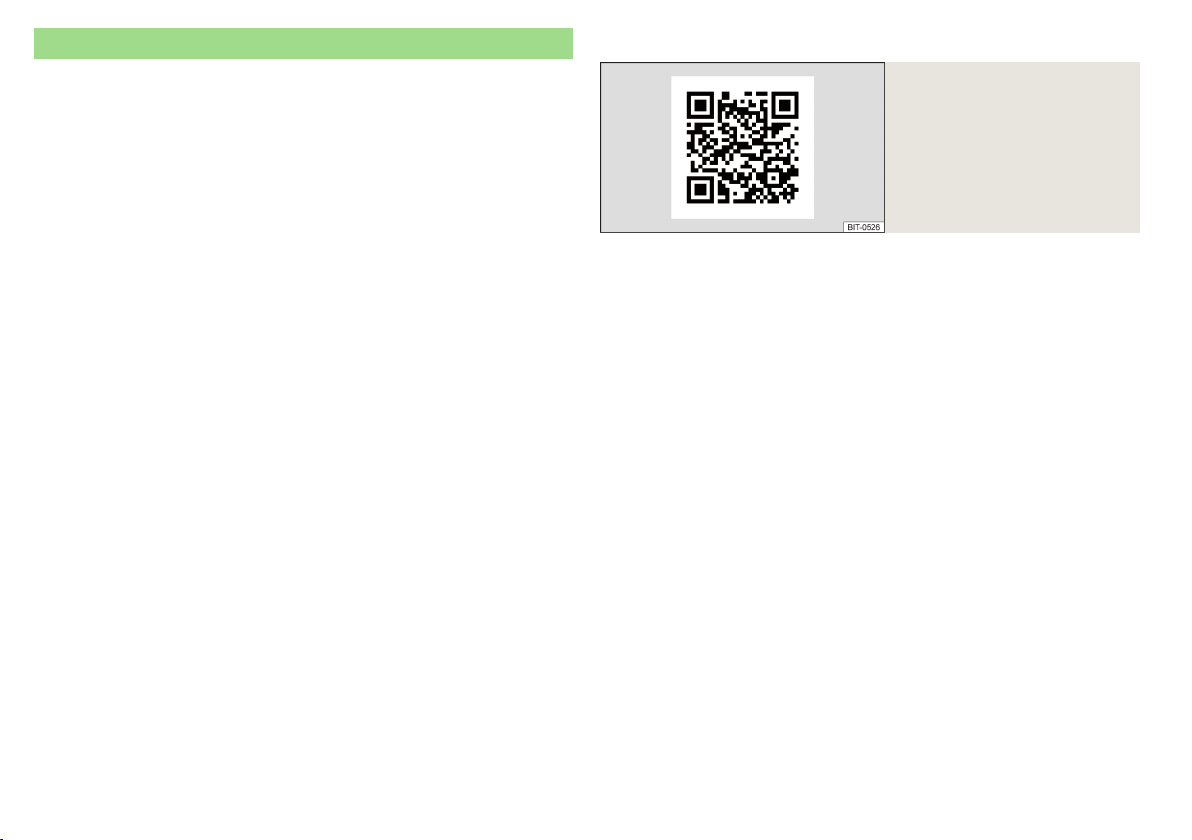
The correct seating position for the driver
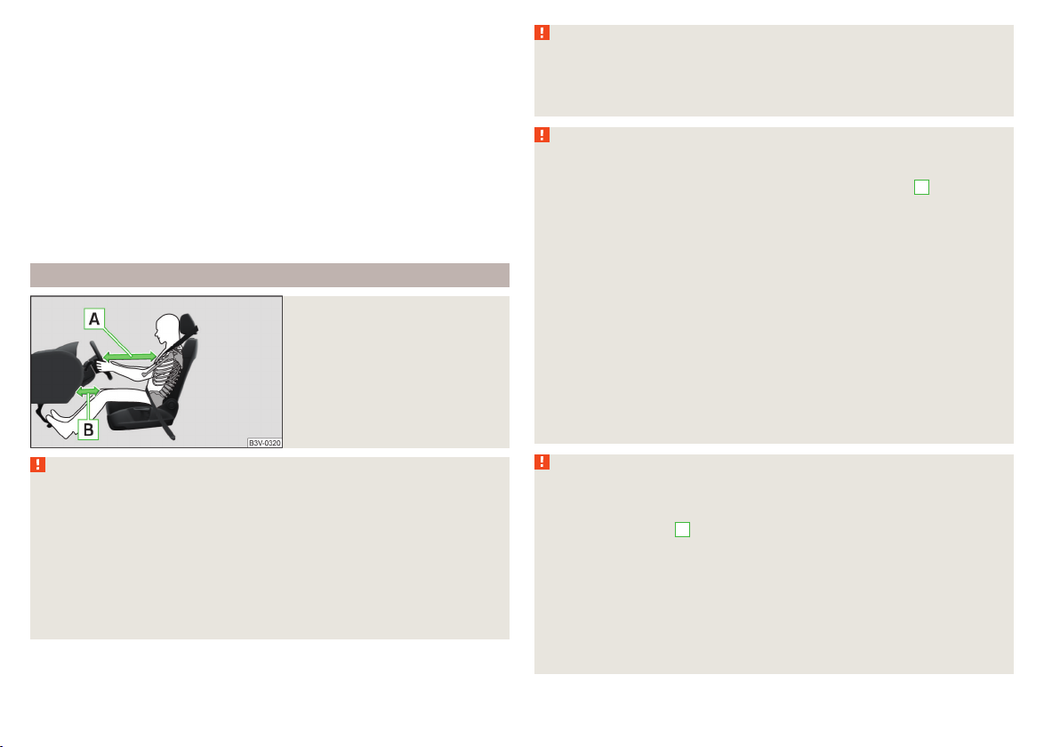
Fig. 2
Correct seated position for the driver/correct steering wheel posi-
tion
Read and observe on page 11 first.
For your own safety and to reduce the risk of injury in the event of an accident,
the following instructions must be observed.
Adjust the driver’s seat in the forward/back direction so that the pedals
can be fully depressed with slightly bent legs.
For vehicles equipped with driver knee airbags, adjust the driver's seat in a
forward/back direction so that there is a gap of at least 10 cm between the
legs and the dashboard in the vicinity of the knee airbag » Fig. 2 - B.
Adjust the seat backrest so that the highest point of the steering wheel
can be reached with your arms at a slight angle.
Adjust the steering wheel so that the distance between the steering
wheel and your chest is at least 25 cm » Fig. 2 - A.
Adjust the headrest so that the top edge of the headrest is at the same
level as the upper part of your head (not for seats with integrated headrests) » Fig. 2 - C.
Correctly fasten the seat belt » page 13, Using seat belts.
WARNING
■
Maintain a distance of at least 25 cm from the steering wheel, and a distance of at least 10 cm between the legs and the dash panel at the height
of the knee airbag. Not maintaining this minimum distance will mean that
the airbag system will not be able to properly protect you - hazard!
■
When driving, hold the steering wheel with both hands firmly on the outer edge in the “9 o'clock” and “3 o'clock” position » Fig. 2. Never hold the
steering wheel in the “12 o'clock” position or in any other way (e.g. in the
middle, inner edge of the steering wheel or similar). Otherwise, you could
sustain serious injuries to the arms, hands and head if the airbag is activated.
■
Ensure there are no objects in the driver's footwell as they may get behind the pedals while driving. You would then no longer be able to operate
the clutch, brake or acceleration pedals.
Adjusting the steering wheel position
Fig. 3 Adjusting the steering wheel position
Read and observe on page 11 first.
The height and forward/back position of the steering wheel can be adjusted.
Swing the safety lever under the steering wheel in the direction of arrow
›
» Fig. 3.
1
Passive Safety
11

Adjust the steering wheel to the desired position. The steering wheel can be
›
adjusted in direction of arrow 2.
Pull the holder in arrow direction 3 until the stop.
›
WARNING
■
Never adjust the steering wheel when the vehicle is moving only when
the vehicle is stationary!
■
The safety lever must always be locked so that the steering wheel cannot
accidentally change position – There is a risk of an accident!
Correct seating position for the front passenger
Read and observe on page 11 first.
For passenger safety and to reduce the risk of injury in an accident, the following instructions must be observed.
Position the front passenger seat back as far as possible. The front passenger must maintain a distance of at least 25 cm to the dash panel so
that the airbag offers the greatest possible safety if it is deployed.
Adjust the headrests so that the top edge of the headrest is at the same
level as the upper part of your head » Fig. 2 on page 11 - C (not for seats
with integrated headrests).
Correctly fasten the seat belt » page 13.
WARNING
■
A distance of least 25 cm to the dashboard should be maintained, otherwise the airbag system will not be able to protect you - There is a risk to
life!
■
Always keep your feet in the footwell when the car is being driven – never place your feet on the instrument panel, out of the window or on the
surface of the seats! You will be exposed to increased risk of injury if it becomes necessary to apply the brake or in the event of an accident. If an airbag is deployed, you could suffer fatal injuries by adopting an incorrect
seated position!
Correct seating position for the passengers in the rear seats
Read and observe on page 11 first.
For the safety of the passengers in the rear seats, and to reduce the risk of
injury in an accident, the following instructions must be observed.
Adjust the headrests so that the top edge of the headrest is at the same
level as the upper part of the head » Fig. 2 on page 11 - C.
Correctly fasten the seat belt » page 13, Using seat belts.
12
Safety

Seat belts
Using seat belts
Introduction
This chapter contains information on the following subjects:
Correct routing of seat belt 14
Fastening and unfastening seat belts 14
Seat belt for the rear middle seat 15
Seat belts that are fastened correctly offer good protection in the event of an
accident. They reduce the risk of an injury and increase the chance of survival
in the event of a major accident.
The seat belts reduce the kinetic energy (energy of motion) to a considerable
extent. They also prevent uncontrolled movements which, in turn, may well result in severe injuries.
When transporting a child the following instructions must be observed
» page 21, Transporting children safely.
WARNING
■
Fasten seat belts before every ride! This also applies to other passengers
- there is a danger of injury!
■
Maximum seat belt protection is only achieved if you are correctly seated
» page 10, Correct and safe seated position.
■
The seat backrests of the front seats must not be tilted too far to the rear
otherwise the seatbelts can lose their effectiveness.
WARNING
Information on dealing with the safety belts
■
The belt webbing must not be jammed in-between at any point or twis-
ted, or chafe against any sharp edges.
■
Make sure you do not catch the seat belt in the door when closing it.
WARNING
Information on the proper use of safety belts
■
Adjust the height of the belt in such a way that the shoulder part of the
belt is roughly positioned across the middle of your shoulder - on no account across your neck.
■
No two persons (also not children) should ever use a single seat belt together.
■
The lock tongue should only be inserted into the lock which is the correct
one for your seat. Wrong use of the safety belt will reduce its capacity to
protect and the risk of injury increases.
■
Many layers of clothing and loose clothing (e. g. a winter coat over a jacket) do not allow you to be correctly seated and impairs proper operation of
the seat belts.
■
Do not use clamps or other objects to adjust seat belts (e.g. for shortening the belts for smaller persons).
■
The seat belts for the rear seats can only fulfil their function reliably
when the seat backrests are correctly locked into position » page 72.
WARNING
Information on the care and maintenance of safety belts
■
The belt webbing must always be kept clean. Soiled belt webbing may impair proper operation of the inertia reel » page 138.
■
The seat belts must not be removed or changed in any way. Do not attempt to repair the seat belts yourself.
■
Check the condition of all the seat belts on a regular basis. If damage to
the parts of the seat belt system (e.g. the strap, the belt connectors, the
retractor, the lock or similar) are detected, the seat belt in question must
be replaced immediately by a specialist.
■
Seat belts which have been subjected to stress in an accident should be
replaced by a specialist garage. The anchorage points for the belts should
also be checked.
Seat belts
13
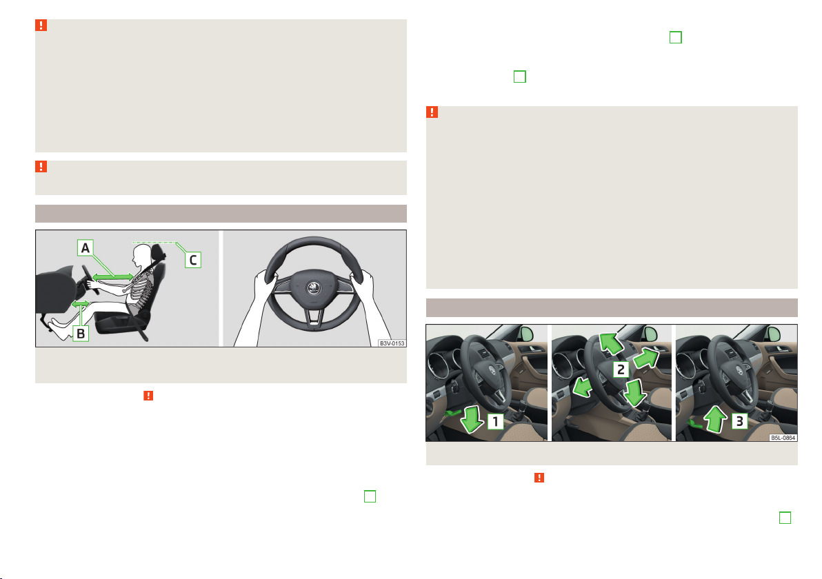
Correct routing of seat belt
Fig. 4 Routing of belt webbing over the shoulders and the lap belt/Routing of belt webbing for an expectant mother
Fig. 5 Seat belt height adjusters for front seats
Read and observe on page 13 first.
It is important that the belt is properly routed to ensure seat belts offer the
maximum protection.
The shoulder belt should be positioned approximately over the middle of your
shoulder (on no account across your neck) and lie flush to the chest » Fig. 4 -
.
The lower part of the belt should run across the pelvis (it should not lie on top
of the stomach) and must always fit snugly » Fig. 4 - .
For pregnant women, the lower part of the belt must be positioned as low
down as possible across the pelvis, to avoid exerting any pressure on the lower abdomen » Fig. 4 - .
Seat belt height adjusters for front seats
Push the return pulley upwards in the direction of arrow » Fig. 5 - .
›
Or: push together the mechanism in the direction of arrows 1 and push the
›
return pulley downwards in the direction of arrow 2 » Fig. 5 - .
Then pull firmly on the belt to ensure that the seat belt height adjuster has
›
correctly locked in place.
WARNING
■
Always ensure that the webbing of the seat belts is properly routed. Seat
belts which are not correctly adjusted can themselves cause injuries even
in minor accidents.
■
A seat belt which is hanging too loose can result in injuries as your body is
moved forward by the kinetic energy produced in an accident and is then
suddenly held firm by the belt.
■
The belt webbing must not run across solid or fragile objects (e.g. pencils,
spectacles, pens, keys etc.). Such objects can cause injury.
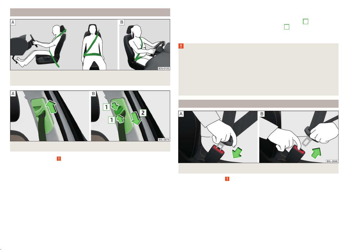
Fastening and unfastening seat belts
Fig. 6 Fastening/unfastening the seat belt
Read and observe
Before fastening the belt
Adjust the headrest properly (does not apply to seats with integrated headr-
›
ests).
Adjust the seat (applies to the front seats).
›
Adjust the belt height (applies to the front seats).
›
Fasten
Use the lock tongue to slowly pull the webbing over your chest and pelvis.
›
on page 13 first.
14
Safety
Insert the lock tongue into the belt buckle » Fig. 6 – that is part of the seat
›
until it clicks into place.
Pull on the belt to check that it has engaged correctly in the lock.
›
Release
Grip the lock tongue and press the red button in the buckle » Fig. 6 - , the
›
lock tongue pops out.
Guide the belt back by hand so that the seat belt does not twist and the
›
webbing rolls up fully.
WARNING
The slot of the belt tongue must not be blocked otherwise the belt tongue
will not lock in place properly.
Seat belt for the rear middle seat
Read and observe
The seat belt for the rear middle seat is anchored in the area of the boot on
the left side of the headliner.
Fasten
Pull the belt with both lock tongues out of the headliner mount.
›
Insert the lock tongue at the end of the belt into the belt buckle on the left
›
side until it is heard to lock in place.
Pull the second lock tongue, which is moveable on the seat belt, over the
›
chest and insert it into the belt buckle on the right side until it is heard to
lock in place.
Pull on the belt to check that it has engaged correctly in the lock.
›
The lock tongue of the belt is shaped differently so that it only fit into the respective belt buckle. If you are not able to insert a lock tongue into the wrong
belt lock you probably tried to put it into the wrong buckle.
Release
Take off the safety belt in the reverse order to how you fasten it.
›
Guide the belt back by hand so that the seat belt does not twist and the
›
webbing rolls up fully.
on page 13 first.
WARNING
■
After releasing the seat belt hold it tight and let it slowly reel up until
both lock tongues lock into the headliner mount and are secured with a
magnet - there is a risk of injury.
■
Never unlock the two buckle tongues at the same time -There is a risk of
injury.
■
The slot of the belt tongue must not be blocked otherwise the belt
tongue will not lock in place properly.
Inertia reels and belt tensioners
Introduction
This chapter contains information on the following subjects:
Inertia reel
Belt tensioners 15
Inertia reel
Each seat belt is equipped with an inertia reel.
When pulling slowly on the seat belt, the belt can move freely. When pulling
sharply on the seat belt, the movement is locked by the inertia reel. The belts
also lock when full braking, when the car accelerates, when driving downhill
and when cornering.
WARNING
If the seat belt does not lock when pulling sharply on it, have it inspected
immediately by a specialist garage.
Belt tensioners
Safety for the driver and front passenger wearing their seat belts is enhanced
by the belt tensioners fitted to the inertia reels of the front three-point seat
belts.
If there is a collision of a certain severity, the seat belts are tightened by the
belt tensioner so that unwanted body motion is prevented.
Belt tensioners are not activated in the event of minor collisions, in the case
of a roll-over and also not in accidents in which no major forces are produced.
15
Seat belts
15
WARNING
■
Any work on the belt tensioner system, including the removal and installation of system components because of other repair work, must only be
carried out by a specialist garage.
■
If the belt tensioners have been deployed, it is then necessary to replace
the entire system.
Note
■
The belt tensioners can also be deployed if the seat belts are not fastened.
■
Smoke is generated when the belt tensioners are deployed. This is not an in-
dication of a fire in the vehicle.
Airbag system
Description of the airbag system
Introduction
This chapter contains information on the following subjects:
System description 16
Airbag deployment 17
Safety instructions 18
The airbag system provides, as a supplement to the seat belts, additional occupant protection during severe frontal and side-on collisions.
The airbag will only provide optimum protection in conjunction with wearing
the seat belt - the airbag is not a substitute for the seat belts.
The functional status of the airbag system is indicated by the indicator light
in the instrument cluster » page 36.
System description
16
Safety
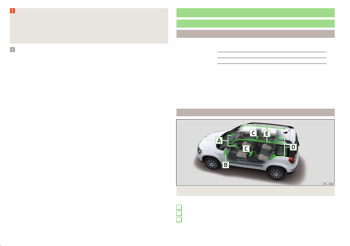
Fig. 7 Airbag installation points
Airbag installation points » Fig. 7
A
Front airbags
B
Driver’s knee airbag
C
Front side airbags
D
Rear side airbags
E
Head airbags
Front airbags - the forward thrust of the driver and of the front passenger is
cushioned when they make contact with the fully-inflated airbag, and the risk
of injury to head and chest is thus reduced.
The front airbags can be identified by the lettering
featured on the steer-
ing wheel and on the dashboard on the passenger side.
Driver´s knee airbag - The forward movement of the body is cushioned when
it makes contact with the fully inflated airbag, and the risk of injury to the legs
of the driver is thus reduced.
The knee airbag is provided with the lettering
on the dashboard on the
driver's side.
Side airbags - the load of the occupants is cushioned when plunged into the
fully inflated airbag. The risk of injury to the entire upper body (chest, stomach
and pelvis) is reduced on the side facing the door.
The side air bags can be identified by a label with the lettering
marked on
the front seat backrests. The rear side airbags are provided with the lettering
in between the entrance area and the rear seat backrest.
Head airbags - the forward movement of the body is cushioned when it makes
contact with the fully inflated airbag, and the risk of injury to head and chest is
thus reduced.
The head airbags are provided with the lettering
marked on the B-pillar
cladding.
Depending on the vehicle equipment, the airbag system consists of the
following parts.
▶
Individual airbags.
▶
Indicator light in the instrument cluster » page 36.
▶
Key switch for the front passenger airbag » page 20.
▶
Warning light for the front passenger airbag in the middle of the dash panel
» page 20.
Airbag deployment
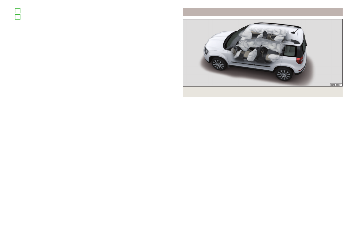
Fig. 8 Inflated airbags
The airbag system is only functional when the ignition is switched on.
When triggered, the airbag fills with gas and unfolds. The inflation of the airbag is carried out in a fraction of a second.
When the airbag inflates, smoke is released. This is not a sign of a fire in the
vehicle.
Triggering conditions
It is not possible to generally determine which deployment conditions apply to
the airbag system in every situation. The important factors here are the hardness of the object with which the vehicle collides, the angle of impact, vehicle
speed etc.
A decisive factor in the deployment of the airbags is the degree of deceleration
at the time. If the vehicle deceleration which occurs and is measured during
the collision remains below the prescribed reference values specified in the
control unit, the airbags are not deployed although the vehicle may well suffer
severe damage to the bodywork as a consequence of the accident.
The following airbags will be deployed in the event of a severe frontal
collision.
▶
Driver’s front airbag.
▶
Front passenger airbag.
▶
Driver’s knee airbag.
Airbag system
17
The following airbags will be deployed in the event of a severe side collision.
▶
Front side airbag.
▶
Rear side airbag.
▶
Head airbag.
When an airbag is deployed, the following events occur.
▶
The hazard warning lights are switched on.
▶
All doors are unlocked.
▶
The fuel supply to the engine is interrupted.
▶
The interior light comes on (if the automatic operation of the interior light is
switched on - position ).
When there is no air bag deployment?
With minor frontal and side collisions, rear collision, overturning of the vehicle
or vehicle roll-over there is no airbag deployment.
Safety instructions
Fig. 9
Safe distance from the steering
wheel and dashboard
WARNING (Continued)
■
If the airbag has been deployed, the airbag system must then be replaced.
■
In the area of the front airbag and the knee airbag, the surface of the
steering wheel and the dashboard should be cleaned using only a dry cloth
or one that has been dampened with water.
WARNING
Information about the front airbags
■
For the driver and front passenger it is important to maintain a distance
of at least 25 cm to the steering wheel or the panel » Fig. 9 - A, If you do
not keep this distance, it means that the airbag system cannot protect you
- there is a risk to life! The front seats and the head restraints must always
also be correctly adjusted to match the body size of the occupant.
■
The front passenger airbag must be deactivated if using a rear-facing
child seat on the front passenger seat » page 19, Airbag deactivation. If
this is not done, there is a risk of the child suffering severe or even fatal
injuries if the front passenger airbag is deployed.
■
No other persons, animals or objects should be placed in front of the occupants in the front seats in the deployment area of the front airbags.
■
The steering wheel and the surface of the dashboard on the passenger
side must not be stickered, covered or modified in any way. No parts (e.g.
cup holders, mobile phone mounts and the like) may be mounted near the
airbag installation points and in the airbag deployment area.
■
Never place objects on the surface of the dashboard on the passenger
side.
WARNING
General information
■
The seat belts and the airbag system can only offer optimum protection
if the driver and passengers are seated properly » page 10.
■
The airbag unleashes enormous force when triggered, which can lead to
serious injuries or fatalities if the driver and passengers are not seated
properly. This applies in particular to children who are transported without
using a suitable child safety seat » page 23.
■
If there is a fault, have the airbag system checked immediately by a specialist garage. Otherwise, there is a risk of the airbag not being activated in
the event of an accident.
18
Safety
WARNING
Information about knee airbags
■
Adjust the driver's seat in a forward/back direction so that there is a gap
of at least 10 cm between the legs and the dashboard in the vicinity of the
knee airbag » Fig. 9 - B. If it is not possible to meet this requirement due
to your body size, visit a specialist garage.
■
The surface of the airbag module in the lower part of the dash panel below the steering column not have stickers attached, be covered or modified
in any other way. Nothing may be attached to the cover of the airbag module or located within the immediate vicinity.
■
Do not attach any bulky and heavy objects (bunch of keys etc.) to the ignition key. These can be ejected by the knee airbag when it is deployed and
can cause injuries.

WARNING
Information about for side and head airbags
■
No objects (e.g. sun visors turned towards the windows) should be located in the deployment area of the side and head airbags. No accessories
(e.g. cup holders etc.) should be fitted to the doors - There is a risk of an
injury!
■
Hang only light clothing on the hooks in the vehicle, do not leave any
heavy or sharp objects in the pockets. Do not use hangers to hang up the
clothes.
■
The airbag system operates using pressure sensors located in the front
doors. For this reason, no adjustments may be carried out to the doors or
door panels (e.g. installation of additional loudspeakers). Additional information » page 132.
■
No excessive force, e.g. through blows, kicks etc. should be applied to the
seat backrests - there is a risk of damage to the side airbags. The side airbags would not be deployed in such a case!
■
Any seat or protective covers which you fit to the driver or front passenger seats must only be of a type expressly authorised by ŠKODA AUTO. In
view of the fact that the airbag inflates out of the backrest of the seat, use
of non-approved seat or protective covers would considerably impair the
protective function of the side airbag.
■
Any damage to the original seat covers or stitching at the installation
points for the side airbags should be immediately repaired by a specialist
company.
WARNING
Information on the use of the airbag system
■
Any work on the airbag system, including the installation and removal of
system components due to other repair work (e.g. removal of the steering
wheel), must only be carried out by a specialist garage. Additional information » page 132.
■
No changes of any sort should be made to parts of the airbag system, the
front bumper or the bodywork.
■
Do not manipulate individual parts of the airbag system, as this might result in the airbag being deployed.
Airbag deactivation
Introduction
This chapter contains information on the following subjects:
Deactivating airbags
Deactivating the front passenger airbag 20
Deactivating airbags
The front passenger airbag can be switched off with the key-operated switch
» Fig. 10 on page 20 - .
We recommend that you ask a ŠKODA service partner to deactivate any other
airbags.
An indicator light indicates that the airbag has been deactivated» page 36.
Deactivating an airbag should be considered in cases such as the ones below.
▶
If a child seat must be used on the front passenger seat, where the child is
transported facing towards the rear» page 21.
▶
If it is not possible to maintain a distance of at least 25 cm between the middle of the steering wheel and chest, despite the driver's seat being correctly
adjusted.
▶
If special attachments are required in the area of the steering wheel because
of a physical disability.
▶
If different seats have been fitted (e.g. orthopaedic seats without side airbags).
WARNING
If an airbag is deactivated at the time of the vehicle being sold, the purchaser must be informed!
19
Airbag system
19
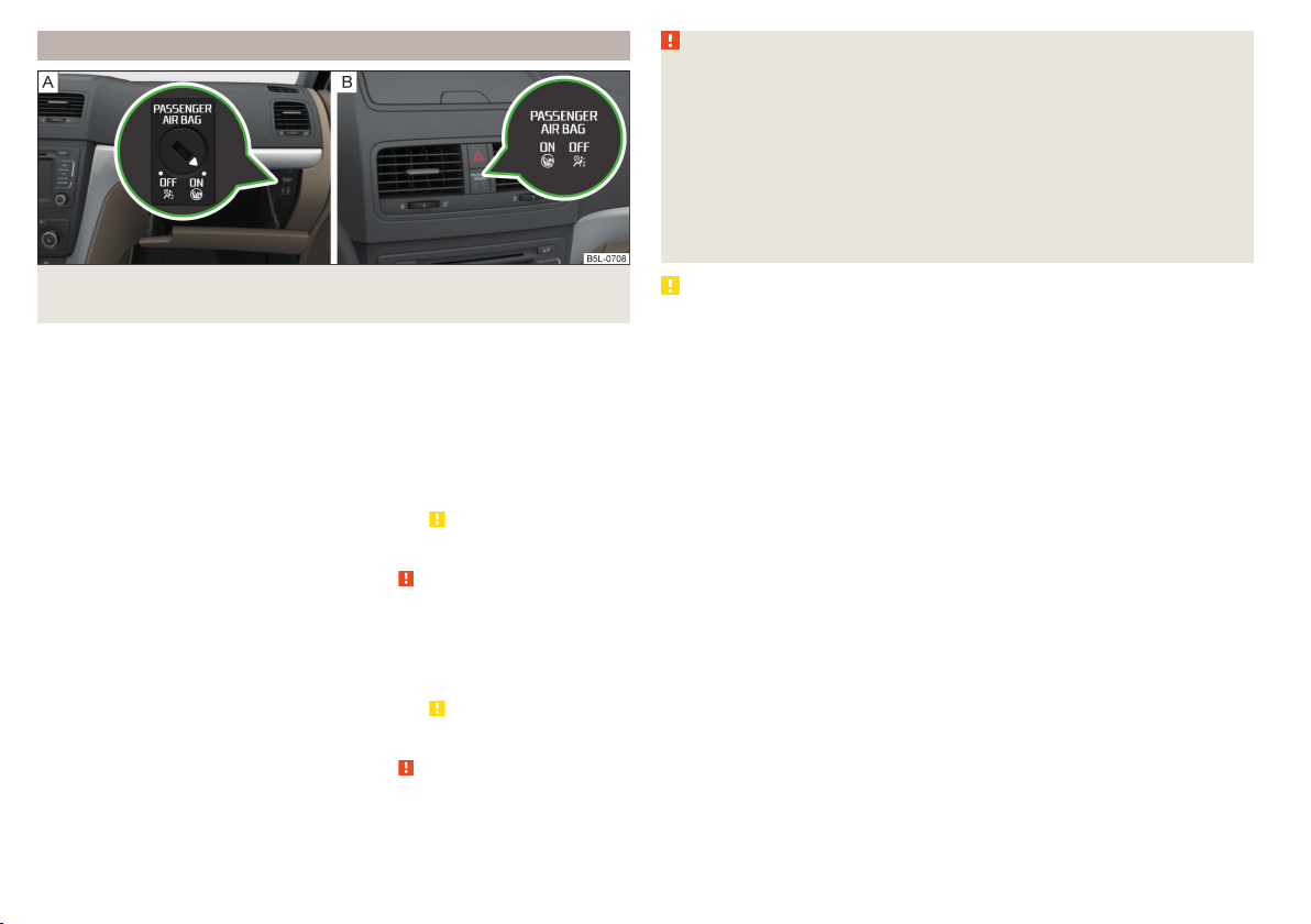
Deactivating the front passenger airbag
WARNING
■
The key cannot be inserted into the key switch while driving. Shocks can
cause the key to turn in the slot and trigger the airbag! The airbag can be
triggered unexpectedly in an accident - it may result in injury or death!
■
The driver is responsible for whether the airbag is switched on or switched off.
■
Only switch off the airbag when the ignition is switched off! Otherwise a
fault can occur in the system for deactivating the airbag.
■
If the
be deployed in the event of an accident! Have the airbag system checked
by a specialist garage immediately.
warning lights flash, the front passenger airbag will not
Fig. 10 Key-operated switch for the front passenger airbag / warning
light for front passenger airbag
Switch positions » Fig. 10 -
The front passenger airbag is deactivated - after the ignition is switched
on, the indicator light
The front passenger airbag is switched on - after switching on the ignition,
the warning light illuminates for 65 seconds
Switch off
Switch off the ignition.
›
Open the storage box on the front passenger's side.
›
Fold the key bit out completely for the radio key » .
›
Carefully insert the key into the key slot in the key switch as far as the stop.
›
Use the key to turn the slot of the key switch carefully into the position
›
Pull the key out of the slot in the key switch » .
›
Close the storage compartment on the front passenger side.
›
Check that the indicator light
›
Switching on
Switch off the ignition.
›
Open the storage box on the front passenger's side.
›
Fold the key bit out completely for the radio key » .
›
Carefully insert the key into the key slot in the key switch as far as the stop.
›
Use the key to turn the slot of the key switch carefully into the position .
›
Pull the key out of the slot in the key switch » .
›
Close the storage compartment on the front passenger side.
›
Check that the indicator light lights up after the ignition is switched on.
›
20
Safety
» Fig. 10illuminates -
lights up after the ignition is switched on.
CAUTION
An insufficiently folded out key bit can damage the key switch!
.
Transporting children safely
Child seat
Introduction
To reduce the risk of injury in an accident, children should only be transported
in child seats!
This chapter contains information on the following subjects:
Use of a child seat on the front passenger seat 22
Use of a child seat on the front passenger seat 22
Child safety and the side airbag 23
Classification of child seats 23
Use of child safety seats which are secured using a seat belt 23
Please refer to the instructions in this Owner's Manual and the child seat manufacturer's instructions with regard to the installation and use of the child
seat.
For safety reasons, we recommend that you always transport children on the
rear seats. Only transport a child on the passenger seat in exceptional circumstances.
Child seats complying with the ECE-R 44 Economic Commission for Europe
standard must be used.
Child seats that comply with the ECE-R 44 standard are identified with a test
mark that cannot be removed: a large E within a circle with the test number
below.
WARNING
■
One should never carry children, and also not babies! - on one's lap.
■
When leaving the vehicle, do not leave children unattended in the vehicle.
In an emergency, they might not be able to get out of the vehicle on their
own or to help themselves. Can be fatal at very high or very low temperatures!
■
The child must be secured in the vehicle during the entire journey! Otherwise, the child would be thrown through the vehicle in the event of an accident, causing fatal injuries to both the child and other occupants.
WARNING (Continued)
■
Children are exposed to an increased risk of injury in the event of an accident if they lean forward or adopt an incorrect seated position when the
vehicle is moving. This particularly applies to children who are transported
on the front passenger seat as they can suffer severe, or even fatal injuries
if the airbag system is deployed!
■
Pay particular attention to the information provided by the manufacturer
of the child safety seat regarding the correct routing of the belt. Seat belts
which are not correctly adjusted can themselves cause injuries even in minor accidents.
■
Safety belts must be checked to ensure that they are running properly.
One should also ensure that the belt is not damaged by sharp-edged fittings.
■
When installing the child seat on the back seat, the corresponding front
seat must be adjusted so that there is no contact between the front seat
and the child seat or the child being transported in a child seat.
■
When installing a child seat in which the child faces forward, adjust the
head restraints so that they are as high as possible.
■
If the headrests still prevent the child seat from being installed, even in
the highest position, you will need to remove them » page 73. After removing the child seat, refit the head restraints.
Note
We recommend that you use child seats from ŠKODA Original Accessories.
These child seats were developed and also tested for use in ŠKODA vehicles.
They meet the ECE-R 44 standard.
Transporting children safely
21
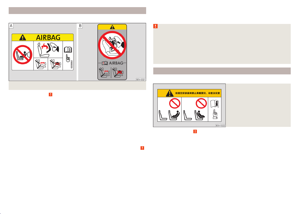
Use of a child seat on the front passenger seat
Does not apply to Taiwan
Fig. 11 Warning labels
Read and observe on page 21 first.
Never use a rearward-facing child restraint system on a seat which is protected by an active airbag. This could cause serious injury to the child, even
death.
This warning is also given on stickers that are located in the following places.
▶
On the front passenger sun visor » Fig. 11 - .
▶
On the B-column on the front passenger side » Fig. 11 – .
The following instructions must be followed when using a child seat on the
front passenger seat.
▶
It is essential to deactivate the front passenger airbag if using a child seat in
which the child is transported with its back facing the direction of travel »
▶
If possible, adjust the front passenger seat backrest so that it is as vertical,
so as to ensure secure contact between the passenger seat backrest and the
back of the child seat.
▶
If possible, move the front passenger seat backwards so that there is no contact between the front passenger seat and the child seat behind it.
▶
Set the height-adjustable front passenger seat as high up as possible.
▶
Set the front passenger seat belt as high up as possible.
▶
With child safety seats in groups 2 and 3, make sure that the loop-around fittings attached to the child seat headrest is positioned in front of or at the
same height as the loop-around fittings on the B pillar on the passenger side.
Adjust the height of the front passenger seat belt so that the belt does not
“jam” in the return pulley. In the event of an accident, there is the risk of injury to the neck of the child carried due to the seat belt!
WARNING
■
Never use a rear-facing child seat on the front passenger seat if the passenger airbag is activated. This child safety seat is positioned in the deployment area of the front passenger airbag. The airbag may cause the child severe, or even fatal injuries, in the event of it being deployed.
■
Once a child seat in which the child is transported with its back to the direction of travel is no longer being used on the passenger seat, the front
passenger airbag should be reactivated.
Use of a child seat on the front passenger seat
Applies to Taiwan
Fig. 12
Warning labels
Read and observe on page 21 first.
No babies, infants or children to be carried on the passenger seat.
A label to this effect can also be found on the front passenger's sun visor
.
» Fig. 12.
22
Safety
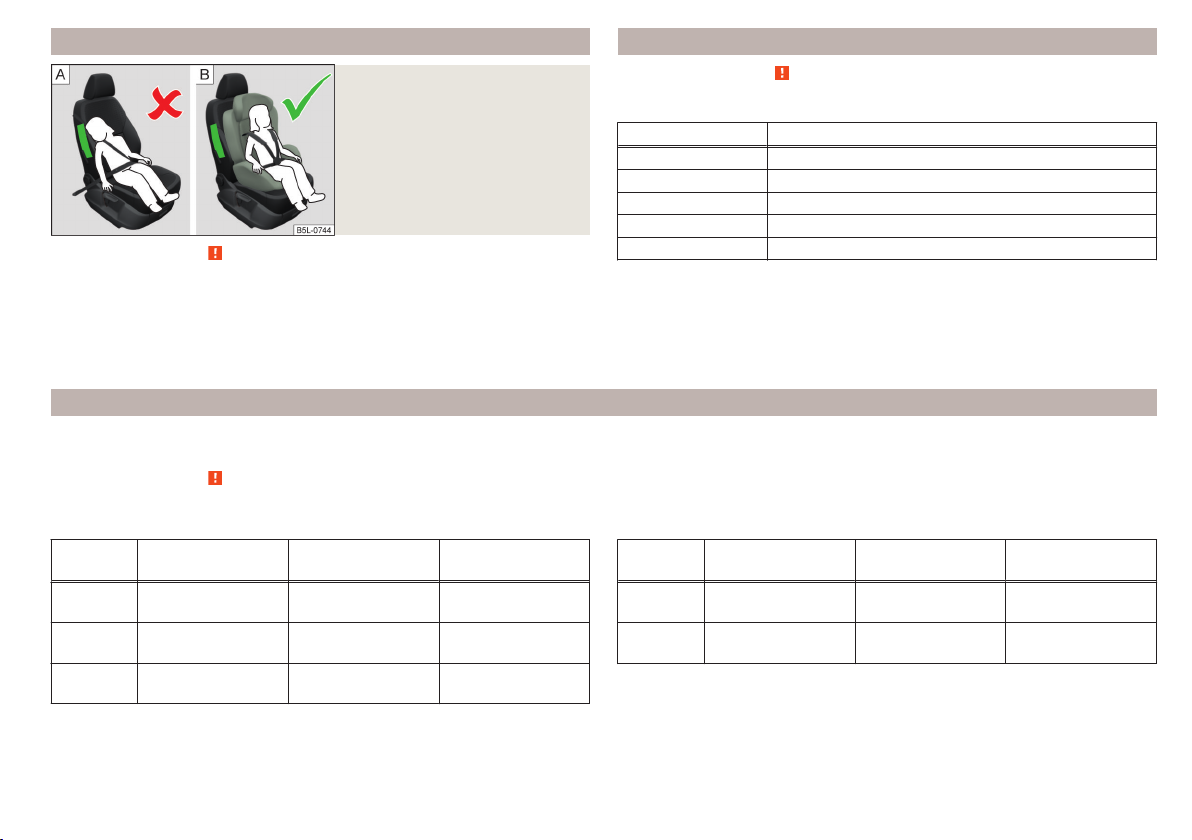
Child safety and the side airbag
Fig. 13
Incorrect seated position of a
child who is not properly secured
– risk from the side airbag/Child
properly protected by safety seat
Classification of child seats
Read and observe on page 21 first.
Classification of child seats according to the ECE-R 44 standard.
Group Weight of the child
0 up to 10 kg
0 up to 13 kg
1 9-18 kg
2 15-25 kg
Read and observe on page 21 first.
3 22-36 kg
The child must not be positioned in the deployment area of the side airbag
» Fig. 13 - .
There must be sufficient room between the child and the deployment area of
the side airbag that the airbag can provide as much protection as possible
» Fig. 13 – .
Use of child safety seats which are secured using a seat belt
Never use a rear-facing child seat on the front passenger seat if the front passenger airbag is activated. This child safety seat is positioned in the deployment
area of the front passenger airbag. The airbag may cause the child severe, or even fatal injuries, in the event of it being deployed.
Read and observe on page 21 first.
Overview of the usability of child seats fastened with a seat belt on each of the seats in accordance with the ECE-R 16 standard.
Group
0
up to 10 kg
0
up to 13 kg
1
9-18 kg
Front passenger
seat
Rear seats
External
U U U
U U U
U U U
Rear seat
Centre
Group
2
15-25 kg
3
22-36 kg
a)
If the middle rear seat is not provided with a headrest, then a child seat of Group 2 or 3 is only to be used
if this has its own built-in headrest. If the child seat of Group 2 or 3 does not have its own built-in headrest, the child seat must be attached to the outer rear seat.
U
“Universal” child seat category - a child seat designed to be attached to
Front passenger
seat
U U U
U U U
Rear seats
External
Rear seat
Centre
a)
a)
the seat using the seat belt.
Transporting children safely
23
Fastening systems
Introduction
This chapter contains information on the following subjects:
attachment points of the
Use of child safety seats with the
Attachment points of the
system
system 24
system 25
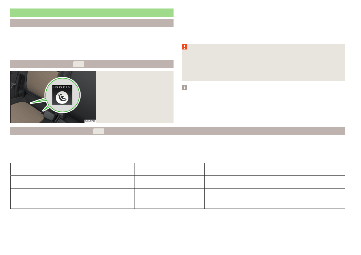
is a system for securing child seats quickly and safely.
There are two fixing eyes between the seat backrest and the seat cushion of
the front passenger seat for fixing a child seat with the
system.
On the rear outside seats, the fixing eyes are located below the upholstery.
The places are marked with labels with the
24
logo » Fig. 14.
WARNING
■
Always refer to the instructions of the manufacturer of the child seat
when installing and removing a child seat with the system.
attachment points of the
system
Fig. 14
Labels of the system
■
Never attach other child seats, belts or objects to the attachment points
intended for the installation of a child seat with the
system – risk of
death!
Note
■
A child seat fitted with the system can only be mounted in a vehicle fit-
ted with a system if the child seat has been approved for this type of vehicle. Further information is available from a ŠKODA Partner.
■
Child seats with the
system can be purchased from ŠKODA Original Ac-
cessories.
Use of child safety seats with the system
Never use a rear-facing child seat on the front passenger seat if the front passenger airbag is activated. This child safety seat is positioned in the deployment
area of the front passenger airbag. The airbag may cause the child severe, or even fatal injuries, in the event of it being deployed.
Overview of the use-ability of the child seats fastened with the system on each of the seats in accordance with the ECE-R 16 standard.
24
Group
0
up to 10 kg
0
up to 13 kg
Safety
Size class of
the child seat
a)
Front passenger seat
b)
Outer rear seats Rear seat middle
E X IL-SU X
E
X IL-SU XD
C
Group
Size class of
the child seat
D
1
9-18 kg
C
B
B1
A
2
15-25 kg
3
22-36 kg
a)
The size category is shown on the label attached to the child seat.
b)
If the front passenger seat is fitted with
- X IL-SU X
- X IL-SU X
system attachment points, it is suitable for the installation of an
a)
Front passenger seat
X
b)
child seat with “Semi-Universal” approval.
Outer rear seats Rear seat middle
IL-SU
IUF
X
IL-SU The seat is suitable for the use of approved child seats in in the “Semi-Universal”category. The “Semi-Universal” category means that the child seat
with the
system is approved for your vehicle. Observe the list of vehicles that comes with the child seat.
IUF The seat is suitable for the installation of a child seat with “Universal” approval and attachment with the system belt.
X The seat is not fitted with system attachment points.
Attachment points of the system
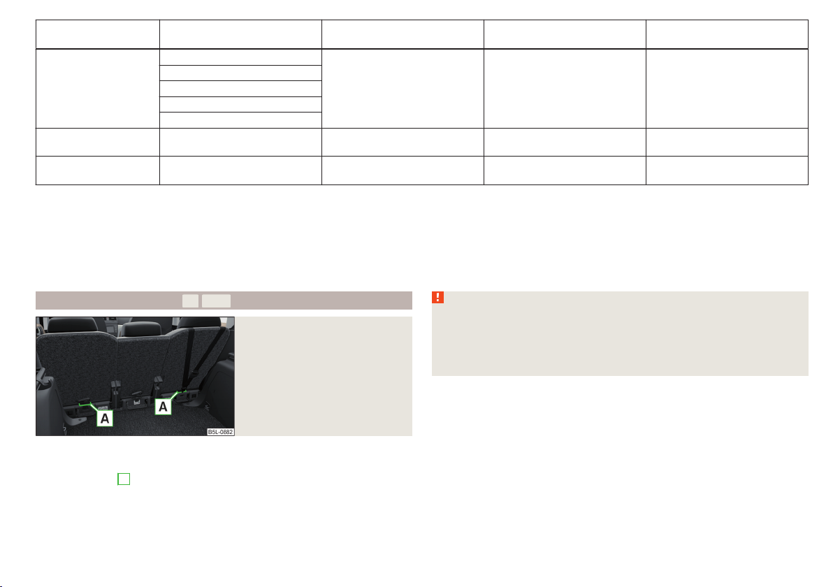
Fig. 15
Attachment points of the
-system
is a fastening system, which restricts the movement of the upper part
WARNING
■
Always refer to the instructions from the manufacturer of the child seat
when installing and removing a child seat with the system.
■
Only use child seats with the
system on the seats with the at-
tachment points.
■
Only ever attach one belt from the child seat to a locking eye.
of the child seat.
The locking eyes A for attaching the belt of a child seat with the
sys-
tem are located on the rear side of the outer rear seat backrests » Fig. 15.
Transporting children safely
25
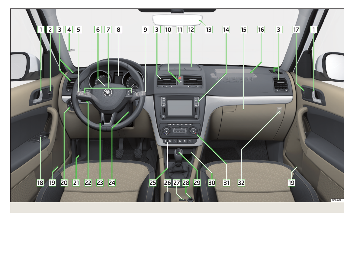
Fig. 16 Cockpit example for LHD models
26
Using the system
Using the system
Cockpit
Overview
1
Door opening lever 50
2
Electric exterior mirror adjustment 67
3
Air outlet vents 96
4
Ticket holder 75
5
Operating lever (depending on equipment):
▶
Direction and high beam 59
▶
Speed regulating system
6
Steering wheel with horn / with driver's front airbag 16
7
Buttons for operating the information system 38
8
Instrument cluster 28
9
Operating lever:
▶
Windscreen wipers and washers 64
▶
Information system
10
Warning light for the front passenger airbag 20
11
Button for hazard warning light system 61
12
Storage compartment 76
13
Interior rear-view mirror 66
14
Depending on specification:
▶
Radio
▶
Infotainment
15
Storage compartment on the front passenger side
16
Front passenger airbag 16
17
Electric window in the front passenger door 54
18
Electric windows 54
19
Storage compartment 76
20
Light switch 58
21
Bonnet release lever 143
22
Regulator for instrument lighting and regulator for headlight
beam range adjustment 29, 58
23
Steering wheel locking lever 11
24
Depending on equipment fitted:
▶
Ignition lock 101
▶
Starter button 101
25
Bar with keys depending on the equipment fitted:
▶
START STOP 102
▶
Traction control TCS 111
▶
Electronic Stability Control ESC 110
▶
Parking aid
▶
OFF ROAD-mode
▶
Tyre pressure control indicator
▶
Park Assist 118
26
Handbrake lever 104
27
121
38
Central locking system 49
28
Depending on equipment fitted:
▶
12-Volt power socket 79
▶
Cigarette lighter
29
Depending on equipment fitted:
▶
Gearshift lever (manual gearbox) 105
▶
Selector lever (automatic gearbox)
30
Storage compartment 76
31
Controls for heating / air conditioning 93
32
Key switch for switching off the front passenger airbag (in front
passenger storage compartment) 20
Note
The layout of the controls on right-hand drive vehicles differs partially from
that shown in this layout» Fig. 16.
82
114
112
123
78
106
Cockpit
27
Instruments and Indicator Lights
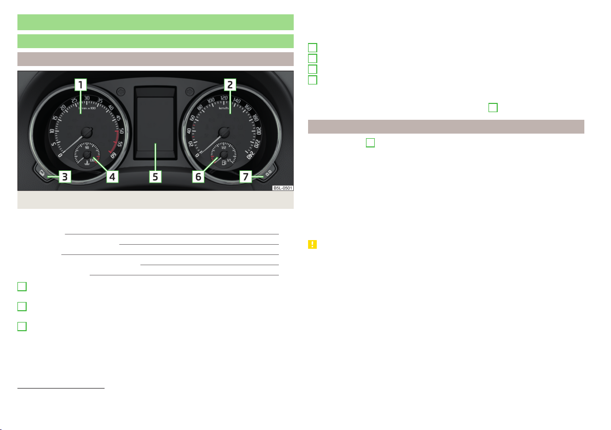
Instrument cluster
Introduction
Fig. 17 Instrument cluster
This chapter contains information on the following subjects:
Rev counter 28
Coolant temperature gauge 29
Fuel gauge 29
Lighting of the instrument cluster 29
Auto Check Control 30
1
Engine revolutions counter » page 28
▶
with warning lights » page 31
2
Speedometer
▶
with warning lights » page 31
3
Operation key:
▶
Setting the time » page 39
▶
Switching the display for the second speedometer on/off1) » page 39
▶
Displaying the distance and days until the next service interval
» page 44
▶
Show AdBlue range1) » page 39
4
Coolant temperature gauge » page 29
5
Display » page 38
6
Fuel gauge » page 29
7
Operation key:
▶
Reset counter for distance travelled (trip) » page 38
▶
Setting the time
▶
Enable / disable the mode selected using the3 button
1)
Rev counter
The tachometer 1 » Fig. 17 on page 28 shows the actual engine speed per minute.
The beginning of the tachometer red scale range indicates the maximum permitted speed for an engine that has been driven-in and has reached operating
temperature.
You should shift into the next highest gear before the red scale of the revolution counter is reached, or select mode D / S on the automatic gearbox.
The gear recommendation is important to note in order to maintain the optimum engine speed » page 39.
CAUTION
The rev counter pointer may only move into the red area for a short time - otherwise there is a risk of engine damage!
1)
Applies to vehicles with a segment display.
28
Using the system

Coolant temperature gauge
Fig. 18
Coolant temperature gauge
The display » Fig. 18 only works if the ignition is switched on.
Cold range - the pointer is in the range A, the engine has not yet reached its
operating temperature. Avoid high speeds and high engine loads.
Operating range - the pointer is in the range B.
High temperature range - the pointer is in the range C. The coolant tempera-
ture is too high. The warning light » page 32 illuminates in the instrument
cluster .
Fuel gauge
Fig. 19
Fuel gauge
The display » Fig. 19 only works if the ignition is switched on.
The tank capacity is 55 litres or approximately 60 litres for Yeti 4x4.
If the fuel level reaches the reserve level A » Fig. 19, the warning light illu-
minates in the instrument cluster» page 36.
WARNING
For the vehicle systems to function correctly, and thus for safe driving,
there must be sufficient fuel in the tank. Never drain the fuel tank completely – risk of accident!
CAUTION
Never drive until the fuel tank is completely empty! Irregular supply of fuel can
cause misfiring, which can result in damage to parts of the engine and the exhaust system.
Note
After filling up, it can occur that during dynamic driving (e.g. numerous curves,
braking, driving downhill and climbing a steep hill) the fuel gauge indicates a
fraction less.
Lighting of the instrument cluster
Fig. 20
Controller for instrument cluster
lighting
The brightness of the of the instrument cluster lighting can be adjusted individually when the dipped beam / parking light is switched.
To Control of lighting brightness the regulator of the instrument cluster
›
turn » Fig. 20.
Note
On vehicles with MAXI DOT display, the brightness of the instrument lighting is
set automatically. A manual brightness adjustment can therefore only have a
limited effect.
Instruments and Indicator Lights
29

Auto Check Control
Vehicle condition
Certain functions and conditions of individual vehicle systems are checked
continuously when the ignition is switched on. If there is a system failure, the
relevant message is displayed in the MAXI DOTDisplay, in conjunction with indicator lights, if necessary, indicator light illumination takes place in the instrument cluster» page 31, Warning lights.
The menu item
play whenever at least one fault message exists. After selecting this menu,
the first of the error messages is displayed.
Several error messages are shown on the display under the message e.g. 1/3.
This indicates that the first of a total of three error messages is being displayed.
Warning lights in the MAXI DOT display
Vehicle status
Engine oil pressure too low » page 33
Check engine oil level
Engine oil sensor defective
Engine-speed limitation » page 30
Water in fuel filter (diesel engine). » page 30
Automatic gearbox DSG overheated » page 30
AdBlue® level too low » page 30
is shown in the main menu of the MAXI DOT dis-
» page 145
Engine-speed limitation
The information about the maximum permissible engine speed is displayed together with this indicator light.
▶
Do not exceed the indicated maximum engine speed!
▶
Continued driving is possible with appropriate caution. Seek assistance from
a specialist garage immediately.
Water in the fuel filter (diesel engine)
The fuel filter with water separator, filters out dirt and water from the fuel.
If too much water is present in the separator, the following information appears on the instrument cluster display.
The indicator light is only shown in the MAXI DOTdisplay.
Illuminates
▶
Continued driving is possible with appropriate caution. Seek assistance from
a specialist garage immediately.
Automatic gearbox DSG
Gearbox overheated. Stop! Log book!
▶
Stop driving! Stop the vehicle and turn off the engine.
You can continue your journey as soon as the warning light disappears.
▶
If the indicator light does not go out, stop driving! Seek help from a specialist garage.
/ AdBlue®level too low
The indicator light and is only shown in the MAXI DOTdisplay.
Further information on refilling of AdBlue ® is shown in the display.
Refill AdBlue (DEF)! Range: ...
ADBLUE RANGE …
The range in the display indicates the distance that can be driven with the remaining AdBlue® left in the tank.
▶
Add AdBlue® » page 142.
ADBLUE NO START IN …
The range in the display indicates the distance to travel, after which no engine
restart is possible, as long as no AdBlue® is added.
▶
Add AdBlue® » page 142.
ADBLUE NO RESTART
It is no longer possible to start the engine.
▶
Refill AdBlue® » page 142.
Water in fuel filter. Log book!
FUEL FILTER SEE MANUAL
Refill AdBlue (DEF)! No engine start in …
Refill AdBlue (DEF)! No engine start possible.
30
Using the system

WARNING
If you have to stop for technical reasons, then park the vehicle at a safe
distance from the traffic, switch off the engine and switch on the hazard
warning light system » page 61. Place the warning triangle at the prescribed distance.
Note
■
If the MAXI DOT display shows warning messages, these messages must be
confirmed in order to access the main menu » page 40 .
■
As long as the operational faults are not rectified, the warning lights are always indicated again. After they are displayed for the first time, the warning
lights continue to be indicated without any extra messages for the driver.
Warning lights
Introduction
This chapter contains information on the following subjects:
Handbrake 32
Braking system 32
Front seat belt indicator light 32
Alternator 32
Door open 32
Coolant 32
Boot lid 32
Power steering / steering lock (KESSY system) 33
Engine oil 33
Stability control (ESC) / Traction control (TCS) 34
Traction control (TCS) deactivated 34
Anti-lock braking system (ABS) 34
Rear fog light 34
Lamp failure 34
Xenon headlights (AFS) 34
Emission control system 35
Preheating unit (diesel) 35
Control of the engine electronics (petrol engine) 35
Diesel particle filter (diesel) 35
Fuel reserve 36
Airbag system 36
Tyre pressure 36
Windscreen washer fluid level 37
Turn signal system 37
Fog lights 37
Cruise control system 37
Brake pedal (automatic transmission)
OFF ROADmode 37
Main beam 37
Display of a low temperature 37
37
The warning lights in the instrument cluster indicate certain functions or
faults.
Some warning lights can be accompanied by acoustic signals and messages in
the display of the instrument cluster.
After switching on the ignition, some warning lights light up briefly as a function test. If the tested systems are OK, the corresponding warning lights go
out a few seconds after switching on the ignition or after starting the engine.
The warning lights are located at the following positions in the instrument
cluster » Fig. 17 on page 28.
▶
Engine revolutions counter
▶
Speedometer
▶
Display
2
5
1
WARNING
■
Ignoring illuminated warning lights and related messages or instructions
in the display of the instrument cluster may lead to serious personal injury
or damage to the vehicle.
■
If you have to stop for technical reasons, then park the vehicle at a safe
distance from the traffic, switch off the engine and switch on the hazard
warning light system » page 61. Place the warning triangle at the prescribed distance.
■
The engine compartment of your car is a hazardous area. The following
warning instructions must be followed at all times when working in the engine compartment » page 142, Engine compartment.
Instruments and Indicator Lights
31

Handbrake
Read and observe on page 31 first.
lights up – the hand brake has been applied.
An acoustic signal will sound if you drive the vehicle above 6 km/h while the
handbrake is still on.
▶
Release the handbrake.
Braking system
Read and observe on page 31 first.
illuminates – the brake fluid level in the brake system is too low.
▶
Park the vehicle, stop driving! Seek help from a specialist garage.
WARNING
A fault to the braking system can increase the vehicle's braking distance There is risk of accident!
Front seat belt indicator light
Read and observe on page 31 first.
lights up - the driver or front passenger has not fastened their seat belt.
At a speed of over 20 km/h, the indicator light flashes and an audible warning sounds at the same time.
If the seat belt is not fastened by the driver or front passenger during the next
approx. 2 minutes, the warning signal is deactivated and the warning light
illuminates permanently.
Alternator
Read and observe
lights up – the battery is not being charged whilst the engine is running.
▶
As the battery discharges while driving, all non-essential electrical loads (e.g.
Infotainment) should be switched off.
▶
Continued driving is possible with appropriate caution. Seek assistance from
a specialist garage immediately.
on page 31 first.
CAUTION
If, in addition to the light the light lights up while driving, stop driving There is a risk of engine damage! Switch off the engine and seek assistance
from a specialist garage.
Door open
Read and observe on page 31 first.
illuminates - one or more doors are open.
On vehicles with MAXI DOT display, this indicator is replaced by a vehicle icon
on the display » page 38 .
Coolant
Read and observe
lights up or flashes – the coolant temperature is too high or the coolant lev-
el is too low.
▶
Stop the vehicle, switch off the engine, and allow the engine to cool down.
▶
Check the coolant level » page 146, Checking and refilling.
If the coolant level is within the specified range and the warning light lights
up again, there may be a malfunction of the cooling fan.
▶
Switch off the ignition.
▶
Check the fuse for the radiator fan, replace if necessary.
If the coolant level and fan fuse are both OK but the warning light lights up
again, stop driving!
▶
Seek help from a specialist garage.
on page 31 first.
Boot lid
Read and observe on page 31 first.
illuminates - the boot lid is open.
On vehicles with MAXI DOT display, this indicator is replaced by a vehicle icon
on the display » page 38 .
32
Using the system

Power steering / steering lock (KESSY system)
Read and observe on page 31 first.
Fault in the power steering
lights up – this indicates a complete failure of the power steering and the
steering assist is no longer working (significantly higher steering forces).
lights up – this indicates a partial failure of the power steering and the
steering forces can be greater.
▶
Switch off the ignition, start the engine again and travel a short distance.
▶
If the warning light does not go out, stop the vehicle, Stop driving!.
Seek help from a specialist garage.
▶
If the warning light does not go out, you can drive on, exercising appropriate caution. Seek assistance from a specialist garage immediately.
Steering column lock not unlocked (System KESSY)
flashes - for vehicles with the KESSY system, the steering lock is not re-
leased.
▶
Move the steering wheel slightly back and forth, thereby facilitating unlocking the steering lock.
▶
If the steering does also not unlock then, the help of a specialist garage is
required.
Steering lock defect (KESSY system)
An audible signal sounds as a warning.
flashes
▶
Park the vehicle, stop driving. After switching off the ignition, it is no longer possible to lock the steering, to activate the electrical components (e.g.
Infotainment ), to switch on the ignition again and to start the engine. Seek
help from a specialist garage.
flashes
▶
Continued driving is possible with appropriate caution. Seek assistance from
a specialist garage immediately.
Disconnecting the vehicle battery
If the vehicle's battery has been disconnected and reconnected, the indicator
light comes on after switching on the ignition.
The warning light should go out after driving a short distance.
Steering column lock faulty.
Steering lock: Workshop!
If, after the motor is restarted and a short drive, the indicator light does not go
out, there is a system error.
▶
Continued driving is possible with appropriate caution. Seek assistance from
a specialist garage immediately.
Engine oil
Read and observe on page 31 first.
Low oil pressure
flashes
▶
Stop the vehicle, switch off the engine, and check the engine oil level.
▶
If the warning light flashes , do not drive an further!even if the oil level
is correct! Also do not leave the engine running at an idling speed.
▶
Seek help from a specialist garage.
Oil pressure: Engine off! Log book!
Engine oil level too low
Illumi-
nates
▶
Stop the vehicle, switch off the engine, and check the engine oil level, top up
Check oil level!
if necessary.
The warning light will go out if the bonnet is left open for more than 30 seconds. If the engine oil is not replenished, the warning light will come on again
after driving about 100 km.
Fault on the engine oil level sensor
flashes
Oil sensor: Workshop!
The warning light flashes several times after switching on the ignition and
there is audible signal.
▶
Continued driving is possible with appropriate caution. Seek assistance from
a specialist garage immediately.
CAUTION
If, under the given conditions, it is not possible to top up with engine oil,
stop driving - there is a risk of engine damage! Switch off the engine and seek
assistance from a specialist garage.
Instruments and Indicator Lights
33

Stability control (ESC) / Traction control (TCS)
Read and observe on page 31 first.
If your vehicle is equipped with the ESC system, the TCS is part of the ESC system.
flashes – the ESC or TCS is currently active.
System fault
lights up – there is an ESC or TCS fault.
▶
Continued driving is possible with appropriate caution. Seek assistance from
a specialist garage immediately.
If the warning light comes on after starting the engine, the TCS may be
switched off for technical reasons.
▶
Switch the ignition off and on again.
If the warning light does not illuminate after you switch the engine back on,
the ASR is fully functional again.
Disconnecting the vehicle battery
If the vehicle's battery has been disconnected and reconnected, the warning
light comes on after switching on the ignition.
The warning light should go out after driving a short distance.
If, after a short drive, the indicator light does not go out, there is a system er-
ror.
▶
You can drive on, exercising appropriate caution. Seek assistance from a specialist garage immediately.
For more information on the ESC system » page 110 or TCS system
» page 111.
Traction control (TCS) deactivated
Read and observe
illuminates – the TCS system is disabled.
on page 31 first.
Anti-lock braking system (ABS)
Read and observe
lights up – there is an ABS fault.
on page 31 first.
The vehicle will only be braked by the normal brake system without the ABS.
▶
Continued driving is possible with appropriate caution. Seek assistance from
a specialist garage immediately.
WARNING
■
If the warning light lights up together with the warning light
» page 32, stop driving! Seek help from a specialist garage.
■
A fault to the ABS system or the braking system can increase the vehi-
cle's braking distance – risk of accident!
Rear fog light
Read and observe on page 31 first.
lights up – the rear fog light is switched on.
Lamp failure
Read and observe
illuminates – one of the vehicle's exterior lights is defective. A message will
appear in the display about the affected lamp.
illuminates within a few seconds after switching on the ignition or when a
light with a faulty bulb is switched on.
Xenon headlights (AFS)
Read and observe on page 31 first.
flashes for 1 minute while driving or after the ignition is switched on - there
is a fault in the xenon headlights (AFS).
The MAXI DOT display shows the following.
Note
With the Xenon headlight “tourist light” (travel mode) activated, the warning
light flashes after switching on the ignition for 10 seconds.
on page 31 first.
34
Using the system

Emission control system
Read and observe on page 31 first.
lights up – there is a fault in the emission control system. The system
makes it possible to drive on in emergency mode - there may be a noticeable
reduction in engine performance.
▶
Continued driving is possible with appropriate caution. Seek assistance from
a specialist garage immediately.
Preheating unit (diesel)
Read and observe on page 31 first.
The warning light comes on after the ignition has been switched on. Once
the light has gone out, the engine can be started immediately. There is a fault
in the glow plug system if the warning light does not come on or illuminates
continuously.
▶
Seek help from a specialist garage.
flashes – there is a fault in the engine management system. The system
makes it possible to drive on in emergency mode - there may be a noticeable
reduction in engine performance.
▶
Continued driving is possible with appropriate caution. Seek assistance from
a specialist garage immediately.
Control of the engine electronics (petrol engine)
Read and observe on page 31 first.
lights up – there is a fault in the engine management system. The system
makes it possible to drive on in emergency mode - there may be a noticeable
reduction in engine performance.
▶
Continued driving is possible with appropriate caution. Seek assistance from
a specialist garage immediately.
Diesel particle filter (diesel)
Read and observe on page 31 first.
The diesel particulate filter separates the soot particles from the exhaust. The
soot particles collect in the diesel particulate filter where they are burnt on a
regular basis.
illuminates – the filter is clogged with soot.
To clean the filter, and where traffic conditions permit »
at least 15 minutes or until the indicator light goes out.
4. or 5. gear engaged (automatic gearbox:S position).
Vehicle speed at least 70 km/h.
Engine speed between 1800-2500 rpm.
If the filter is properly cleaned, the warning light extinguishes.
If the filter is not properly cleaned, the warning light does not go out and
the warning light begins to flash.
▶
Continued driving is possible with appropriate caution. Seek assistance from
a specialist garage immediately.
WARNING
■
Always adjust the speed and driving style to the actual weather, road, ter-
rain and traffic conditions.
■
The diesel particulate filter reaches very high temperatures - there is a
fire hazard and serious injury could be caused. Therefore, never stop the
vehicle at places where the underside of your vehicle can come into contact
with flammable materials, such as dry grass, undergrowth, leaves, spilled
fuel or the like.
CAUTION
■
As long as the warning light illuminates, one must take into account an
increased fuel consumption and a power reduction of the engine.
■
Using diesel fuel with an increased sulphur content can considerably reduce
the life of the diesel particle filter. A ŠKODA partner will be able to tell you
which countries use diesel fuel with a high sulphur content.
Note
We encourage you to avoid constant short journeys. This will improve the combustion process of the soot particles in the diesel particulate filter.
, drive as follows for
Instruments and Indicator Lights
35

Fuel reserve
Read and observe on page 31 first.
illuminates – the fuel level in the fuel tank is at the reserve level (approxi-
mately 9 litres).
An audible signal sounds as a warning.
▶
Please refuel » page 139.
Note
The text in the display goes out after refuelling and driving a short distance.
Airbag system
Read and observe
System fault
lights up - there is a fault in the airbag system.
Error: Airbag
▶
Seek help from a specialist garage.
The front passenger airbag has been disabled with the key switch
illuminates for around 4 seconds after the ignition has been switched on.
One of the airbags or a belt tensioner has been disabled by the diagnostic
tool
illuminates for around 4 seconds after the ignition is switched on and then
flashes for approximately 12 seconds.
Airbag / belt tensioner deactivated.
WARNING
When a fault in the airbag system occurs, there is a risk of the system not
being triggered in the event of an accident. Therefore, this must be
checked immediately by a specialized garage.
Tyre pressure
Read and observe
Change of tyre pressure values
lights up - there was a pressure change in one of the tyres.
on page 31 first.
on page 31 first.
An audible signal sounds as a warning.
▶
Immediately reduce speed and avoid sudden steering and braking manoeuvres.
▶
Stop the vehicle, turn the ignition off and check the tyres and their inflation
pressures » page 151.
▶
Correct the tyre pressure, if necessary or replace the affected wheel
» page 155 or use the repair kit » page 159.
▶
Save the tyre pressure values in the system » page 123.
System fault
flashes for approximately 1 minute and remains lit – there may be a fault in
the tyre pressure monitoring system.
▶
Stop the vehicle, turn the ignition off and start the engine again.
If the warning light flashes again after the engine has started, there is a
system error.
▶
Continued driving is possible with appropriate caution. Seek assistance from
a specialist garage immediately.
Disconnecting the vehicle battery
If the vehicle's battery has been disconnected and reconnected, the indicator
light comes on after switching on the ignition.
The warning light should go out after driving a short distance.
If, after a short drive, the indicator light does not go out, there is a system er-
ror.
▶
Continued driving is possible with appropriate caution. Seek assistance from
a specialist garage immediately.
Other incidents
The following reasons can explain the warning light being illuminated.
▶
The vehicle is loaded on one side. Distribute the load evenly.
▶
The wheels of one axle are loaded more heavily (e.g. when towing a trailer or
when driving uphill or downhill).
▶
Snow chains are mounted.
▶
A wheel has been changed.
CAUTION
Under certain circumstances (e.g. sporty style of driving, wintry or unpaved
roads) the warning light can be delayed or does not light up at all.
36
Using the system

Windscreen washer fluid level
Read and observe on page 31 first.
illuminates – the windscreen washer fluid level is too low.
▶
Top up the windscreen washer fluid » page 144.
Turn signal system
Read and observe on page 31 first.
flashes – the left turn signal is turned on.
flashes – the right turn signal is turned on.
If there is a fault in the turn signal system, the warning light flashes at twice
its normal rate (does not apply when towing).
When the hazard warning light system is switched on, this will cause all of the
turn signal lights as well as both warning lights to flash.
Fog lights
Read and observe on page 31 first.
illuminates – the fog lights are switched on.
Cruise control system
Read and observe on page 31 first.
lights up – the vehicle speed is regulated by the cruise control system.
Brake pedal (automatic transmission)
Read and observe on page 31 first.
lights up – apply the brake.
flashes – the hill descent assistant is engaged at the moment.
Main beam
Read and observe on page 31 first.
lights up – the main beam or the headlight flasher is switched on.
Display of a low temperature
Read and observe on page 31 first.
illuminates – the outside temperature is below +4 °C.
WARNING
Even at temperatures of around +4 °C, black ice may still be on the road
surface! You should therefore not only rely on the outside temperature display for accurate information as to whether there is ice on the road.
OFF ROADmode
Read and observe on page 31 first.
illuminates – the conditions for the engagement of OFF ROADmode are
met» page 112, OFF ROAD Mode.
Instruments and Indicator Lights
37

Information system
Driver information system
Introduction
This chapter contains information on the following subjects:
Display in the instrument cluster 38
Setting the time 39
Display of the second speedometer 39
Display of AdBlue range 39
Gear recommendation 39
Display in the instrument cluster
Fig. 21 Display types: MAXI DOT / segment display
Depending on the vehicle's equipment, the information system uses the display in the instrument cluster to provide the following information » Fig. 21.
1
Compass display
2
Engaged gear / gear recommendation
Selector lever positions for the automatic gearbox
Warning lights of the START-STOP system
3
Time
4
Driving data (multi-function display - MFD)
Warning lights
Information messages
1)
Door alarm
Service interval display
5
Outside temperature
6
Total distance travelled
Speed regulating system
7
Distance travelled by resetting the memory (trip)
8
Engaged gear / gear recommendation
Selector lever positions for the automatic gearbox
9
Driving data (multi-function display - MFD)
10
Distance travelled by resetting the memory (trip)
Total distance travelled / Second speedometer display
Speed regulating system
Service interval display
Information messages
Reset counter for distance travelled (trip)
Press button B » Fig. 22 on page 39.
›
Door, luggage compartment and bonnet alarm
When the door or luggage compartment / bonnet is open, a warning indicator
appears in theMAXI DOT display. An acoustic signal will also sound if you drive
the vehicle above 6 km/h when a door is open.
Segment display - with the door or tailgate open, the warning light or.
illuminates in the instrument cluster. An acoustic signal will also sound if
you drive the vehicle above 6 km/h when a door is open.
CAUTION
remove the ignition key when touching the display,(. E.g. when cleaning) (As
regards vehicles with the KESSY system, switch off the ignition and open the
driver's door) - otherwise there is a risk of damage to the display.
1)
Applies to vehicles with factory-installed navigation system.
38
Using the system

Setting the time
Fig. 22
Buttons in the instrument cluster
Use buttons A and B to set the time» Fig. 22.
A
The choice to change the display (hours or minutes).
B
The change of the displayed value.
In vehicles equipped with the MAXI DOT display, it is also possible to set the
Time
in the Time menu » page 43, Menu item
Settings
.
Display of the second speedometer
The display can show the current speed in mph1). This feature is provided for
driving in countries with different speed units.
MAXI DOT display
The display of the second speedometer can be set in the
item » page 43, Menu item
Segment display
Press buttonA » Fig. 22 on page 39repeatedly, until the odometer display
›
flashes.
Press the B button while the display flashes.
›
The second speedometer is displayed instead of the odometer. The display of
the second speedometer is switched offin the same manner as it is switched
on.
Settings
.
Alt. speed dis.
menu
Display of AdBlue range
The display shows the distance in km that can still be driven with the remaining AdBlue tank capacity.
MAXI DOT display
The display of AdBlue range is part of the multi-function display » page 41,
Information overview.
Segment display
Press button A » Fig. 22 on page 39 repeatedly until instead of total kilome-
›
tres travelled, the AdBlue Range is displayed.
Wait around 5 seconds - the system switches to the initial setting.
›
Gear recommendation
Fig. 23 Information on the selected gear / Gear recommendation
A suitable engaged gear or, where appropriate, a recommended gear is displayed, with the aim of conserving the life of the engine and increasing driving
efficiency.
For vehicles with automatic transmission the recommended gear will be
shown provided the mode for manual switching (Tiptronic) is selected.
Display
MAXI DOT display » Fig. 23
Optimal gear engaged
Gear recommendation (e.g. means that it is advantageous to switch
from 3. to 4. gear)
Segment display » Fig. 23
Optimal gear engaged
Recommended gear
- Recommends that you change up to a higher gear
1)
For models with the speedometer in mph, the second speedometer is displayed in km/h.
Information system
39

- Recommends that you change down to a lower gear
▶
On vehicles with a manual gearbox, the recommended gear and an arrow symbol is displayed (e.g. means that it is advantageous to
change up from a lower gear to 4. gear).
▶
On vehicles with an automatic gearbox in manual shifting mode (Tiptronic), gearcurrently engaged and an arrow symbol is displayed, (e.g.
means that it is advantageous to change up from 4 to a higher gear).
WARNING
The driver is always responsible for selecting the correct gear in different
driving situations (e.g. when overtaking).
Operation via the multifunction steering wheel
Operation of the information system
Operation via the operating lever
Operating the multifunction display
A
Press (up or down) - select data / Setting values
B
Press - show / confirm entry
Operating the MAXI DOT display
A
Press (up or down) - move to the selected menu
Hold (up or down) - display main menu
B
Press - confirm selected menu item
40
Using the system
Fig. 24
Buttons on the control lever
Fig. 25 Buttons/dials on the multifunction steering wheel
Buttons/dials on the multifunction steering wheel
Press- Change frequency range (e.g. FM/AM/DAB) / Switch audio source
(e.g. SD card/USB input)
A
Turn - sets the volume
Press - sound on / off
Skip to next track/station
Switch to previous track/station
Switch on/off voice control
Press - display the phone menu; accept/end the call; select contact
Hold - repeat last call; reject call
Operating the multifunction display
B
Turn - select data / set values
Press - show / confirm entry
Operating the MAXI DOT display
Hold - display main menu
Press - return to a previous level in the menu
B
Turn - move in the selected menu
Press - confirm selected menu item
Note
Depending on equipment not all functions may be available. The system indicates this through a text message on the display.

Multifunction display (MFD)
Introduction
This chapter contains information on the following subjects:
Information overview
Warning when exceeding the set speed 41
Memory 42
The driving data is displayed in the multifunction display when is ignition is
switched on. After the ignition is switched on, the function that was last selected before switching off the ignition is displayed.
If vehicles with MAXI DOTdisplay do not show the driving data after switching
on the ignition, select the menu item
» page 42, MAXI DOT display.
On vehicles with a MAXI DOT display, there is an option to fade out the units
and some of the information » page 43, Menu item
Note
If the display of the second speed is activated in mph, the current speed is not
indicated in km/h on the display.
Information overview
Overview of driving data (depending on the vehicle equipment fitted).
Exterior temperature - For vehicles with a MAXI DOT display this information
is always shown.
Driving time - driving time since last clearing the memory.
Current fuel consumption - when the vehicle is stationary or moving slowly,
the fuel consumption is displayed in l/h (in models in some countries the following appears --,- km/l).
Average fuel consumption - is calculated continuously since the last clearing
of the memory. After erasing the memory, no data will appear for the first 300
m driven.
Range - drive distance in km which can be covered with the existing tank capacity and with the same driving style. If you drive more efficiently this value
can increase.
MFD
in the main menu and confirm
Settings
.
AdBlue® range - drive distance in km which can be covered with the existing
AdBlue®tank capacity and with the same driving style. If you drive more efficiently this value can increase.
Distance driven - distance driven since the memory was last cleared.
Average speed - value constantly recalculated, for distance since last clearing
41
the memory. After erasing the memory, no data will appear for the first 300 m
driven.
Current Speed - digital speedometer.
Oil temperature - if the temperature is lower than 50 °C or if there is a fault in
the system for checking the oil temperature, the
Warning when the preset speed is exceeded - allows the setting of a speed
limit where, if exceeded, an acoustic warning signal and a warning message
appears on the display of the instrument cluster.
symbols are displayed.
Warning when exceeding the set speed
The system offers the possibility to set a speed limit beyond which an acoustic
warning signal will sound and the following warning message (MAXI DOT Display) and the symbol appears in the display of the instrument cluster.
Adjust the speed limit while the vehicle is stationary
Select the menu item
›
Set the desired speed limit.
›
Confirm the set value, or wait several seconds; your settings will be saved
›
automatically.
Adjusting the speed limit while the vehicle is moving
Select the menu item
›
Drive at the desired speed.
›
Confirm the current speed as the speed limit.
›
The set speed limit can be manually adjusted later if needed.
Reset speed limit
Select the menu item
›
By confirming the speed stored in the memory, the speed limit is reset.
›
The set driving mode remains stored even after switching the ignition on and
off.
Speed warning
Speed warning
Speed warning
at () or () and confirm.
at () or () and confirm.
at () or () and confirm.
Information system
41

Memory
MAXI DOT display
Fig. 26
Multi-function display - memory display
The system stores data from the two memories described below, which are
then displayed at position A» Fig. 26.
“1” - Single-trip memory
Drive data is stored from when the ignition is switched on to when it is switched off. If the trip is continued within 2 hours after switching off the ignition,
new data will also flow into the calculation of the current driving information.
If the trip is interrupted for more than 2 hours, the memory is automatically
erased.
“2” - Long-term memory
The memory saves data from any number of individual journeys up to a total of
19 hours and 59 minutes or 1999 kilometres driven (), and up to a total of
99 hours and 59 minutes or 9999 kilometres driven ().
The indicator is automatically set back to zero if one of the indicated values is
exceeded.
For the Storage choice, repeatedly confirm the selected indication and select
›
the desired memory.
For Deleting the memory for the selected information, hold down the button
›
confirming the specification.
The following driving data is stored in different memory banks.
▶
Average fuel consumption.
▶
Distance driven.
▶
Average speed.
▶
Driving time
Note
Disconnecting the vehicle battery will delete all memory data.
Introduction
This chapter contains information on the following subjects:
Menu item
Menu item
Menu item
Menu item
Menu item
The MAXI DOT display is a user interface which, depending on the equipment
configuration, provides information about the Infotainment, the multifunction
display, the assistance systems etc. Furthermore, it enables some other functions of your vehicle to be set.
The menus with details can be operated and displayed using the buttons on
the operating lever or the multifunction steering wheel » page 40.
Main menu items (depending on vehicle equipment)
■
MFD
■
Audio
■
Navigation
■
Phone
■
Aux. heating
■
Assist systems
■
Vehicle status
■
Settings
■
If warning messages are displayed, these messages must be verified to ac-
cess the main menu.
■
The menu chosen always shifts to one of the higher levels after 10 seconds if
the display is not currently active.
Menu item
The following information is displayed in the
▶
Driving recommendations
▶
Compass
▶
Last destinations
Navigation
Audio
Phone
Assistants
Settings
(Multifunction display) » page 41
» page 43
» page 42
» page 43;
» page 97
» page 43
» page 30
» page 43
Note
Navigation
Navigation
menu item.
42
43
43
43
43
42
Using the system

Menu item
The following information is displayed in the
Radio
▶
Currently playing station (name/frequency).
▶
The selected frequency range (e.g. FM) optionally with the number of the station button (e.g. FM 3), if the station is stored in the memory list.
▶
List of available stations (if more than 5 stations can be received).
▶
TP traffic announcements.
Media
▶
Name of the track being played, if necessary, further information regarding
Audio
Audio
menu item.
title (e.g. artist, album name), if this information is stored as a so called ID3
tag on the audio source.
Menu item
The call list with the following symbols is displayed in the
Incoming call
Outgoing call
Missed call
Symbols in the display
Charge status of the telephone battery
A telephone is connected to the unit
Missed calls (if there are several missed calls, the number of calls is shown
Phone
Signal strength
Telephone
menu item.
1)
1)
next to the symbol)
Menu item
In the
Assistants
Assistants
menu item, the fatigue detection can be enabled/disabled
» page 122.
Menu item
Settings
There is an option to change certain settings using the display. The following
information can be selected (depending on the equipment installed in the vehicle).
Language
Setting the language for the texts shown on the display.
MFD data
Switching on/off certain information of the multifunction display.
Comfort
-Turn on / off or adjust the following functions.
Switch on/off the audible signal indicating activation
ATA confirm
of the anti-theft alarm system» page 51, Anti-theft
alarm system.
Central locking
Switch on/off the central locking and automatic locking function» page 50, Individual settings.
Setting the comfort controls for the driver window or
Window op.
for all windows » page 55, Window convenience operation.
Activate/deactivate the function for lowering the mirror on the front passenger side when in reverse
Mirror down
gear» page 67, Tilting the mirror area of the front
passenger mirror (vehicles with electrically adjustable
driver's seat).
Activation / deactivation of the synchronous exterior
Mirror adjust.
mirror function settings» page 67, Setting the mirror surfaces synchronously.
Factory setting.
Lights & Vision
- Turn on / off or adjust the following functions.
Coming Home
Leaving Home
Dayt. r. light
Resetting the
Comfort
menu to the factory setting.
Activate/deactivate and adjust the light duration of
the COMING HOME function» page 61.
Switch on/off and adjust the light duration of the
LEAVING HOME function» page 61.
Activate/deactivate the daylight driving
light» page 59, Daylight running lights (DAY LIGHT).
Activate/deactivate the function of the automatic
Rear wiper
rear window wiping» page 65, Automatic rear wiper.
Lane ch. flash
Activate/deactivate the Comfort Indicating function» page 59, Comfort signalling.
1)
This function is only supported by some mobile phones.
Information system
43

Travel mode
Factory setting.
Coasting
-Enable / disable the idle position (coasting) for vehicles with automat-
Activate/deactivate the travel mode feature» page 62.
Resetting
Lights & Vision
menu item to the factory set-
ting.
ic transmission » page 108, Driving in neutral (“coasting”).
Time
- Setting the time, the time format (24 or 12 hour) and the change-over to
summer/winter time.
Winter tyres
- Setting the speed and the switching on and off of the acoustic signals when exceeding this speed. This function is, for example, used for winter
tyres where the maximum permissible speed is lower than the maximum
speed of the vehicle » page 150, Wheels and tyres. If the set speed is exceeded, an audible signal sounds and the following message appears in the information display.
Units
- Setting the units for temperature, consumption and distance travelled.
Assistants
- Adjustment of the sound in Park Assist» page 114, Parking aid
(ParkPilot).
Alt. speed dis.
Turn on / off the display of the second speedometer in
mph1)» page 39, Display of the second speedometer.
Service
Display the distance travelled and the days until the next service
date» page 44, Service interval display.
Factory setting.
- Resetting the display functions to factory settings.
Service interval display
Introduction
This chapter contains information on the following subjects:
Prompt in the MAXI DOT display
Prompt in the segment display 44
Resetting the service interval display 45
The service interval display shows the kilometres or days until the next service
event.
44
Information regarding the service intervals » page 133.
Prompt in the MAXI DOT display
Messages before reaching the scheduled service date
Before the next service date has been reached, the symbol as well as a message about the mileage or days until the next service event appears in the display after switching on the ignition.
Messages upon reaching scheduled service date
Once the service appointment is reached, a message appears in the display after switching on the ignition.
Displaying the distance and days until the next service interval
Messages about the remaining kilometres and days until the next service date
can be displayed at any time when the ignition is switched on by going to the
Service
menu item » page 43, Menu item
Settings
or from the
Vehicle status
in the
main menu of the Maxi DOTdisplay. » page 42.
Prompt in the segment display
Fig. 27
Segment display: Example of a
message
Image description » Fig. 27
Service due
A
Differentiating between types of service
▶
- Oil change service
▶
- Inspection
B
- Days remaining until the next service interval
C
Kilometres remaining until the next service interval
1)
For models with the speedometer in mph, the second speedometer is displayed in km/h.
44
Using the system

Messages before reaching the scheduled service date
Before the next service date has been reached, the symbol» Fig. 27 as well as
a message about the mileage or days until the next service event appears in
the display for approx. 10 seconds after switching on the ignition.
Messages upon reaching scheduled service date
As soon as the service date is reached, the flashing icon and the message
appears in the display for about 20 seconds after the ignition is switched on.
Displaying the distance and days until the next service interval
Messages regarding kilometres and days until the next service date can be displayed at any time with the ignition switched on by pressing the button again
A
» Fig. 22 on page 39.
The following is shown in the displayed» Fig. 27 (First information on theOil
Change Service, By pressing the key again A » Fig. 22 on page 39 Information
on Inspection).
Resetting the service interval display
We recommend that the display reset is completed by a specialist garage.
We recommend that you do not reset the service interval display yourself. Incorrectly setting the service interval display could cause problems to the vehicle.
Variable service interval
For vehicles with variable service intervals, after resetting the oil change service display in a specialist garage, the values of the new service interval are displayed, which are based on the previous operating conditions of the vehicle.
These values are then continuously matched according to the actual operating
conditions of the vehicle.
SmartGate
Introduction to the subject
Fig. 28
QR code with reference to the
ŠKODA websites
SmartGate is a system that transmits certain driving data (such as fuel consumption, speed or similar) via Wi-Fi and Wi-Fi Direct.
The ŠKODA applications installed in a supported external device (e.g. phone,
tablet) give the option to further transmit the received data.
Some ŠKODA applications can be displayed in the Infotainment display by
means of a SmartLinkconnection » Owner's Manual Infotainment.
Read in the QR code » Fig. 28 using the respective application on your external
device or enter the following address in the web browser to open the website
with an overview of the available applications, compatible devices and other
information about SmartGate.
http://go.skoda.eu/connectivity-smartgate
CAUTION
■
To increase the access security to the transmitted vehicle data, once the
ŠKODA application has been started, you are requested to change the password/PIN code if the default password/PIN code has not yet been changed
» page 47, Password/PIN code. It is not possible to start the ŠKODA applica-
tion without changing it.
■
ŠKODA accepts no responsibility for any problems caused by incompatibility
or improper functioning of the external devices.
Information system
45

connection to SmartGate using Wi-Fi
This type of connection is intended for external devices running Android and
iOS operating systems.
Connecting to an Android external device
Switch on the ignition.
›
Switch on Wi-Fi in the external device that is to be connected and search for
›
available Wi-Fi networks (see Owner's Manual for the external device).
In the menu of the detected networks, select the “SmartGate_...”1) menu item.
›
Enter the password (vehicle identification number using uppercase let-
›
ters» page 47).
In the external device that is to be connected to, start the SmartGate appli-
›
cation.
Then follow the instructions in the manual, which is included in the
›
SmartGate application.
With SmartGate, a maximum of four external devices can be connected simultaneously using Wi-Fi, with as many launched ŠKODA applications as required.
Connecting to an external iOS device
Switch on the ignition.
›
Switch on Wi-Fi in the external device that is to be connected and search for
›
available Wi-Fi networks (see Owner's Manual for the external device).
In the menu of the detected networks, select the “SmartGate_...”1) menu item.
›
Enter the password (vehicle identification number using uppercase let-
›
ters» page 47).
With SmartGate, a maximum of four external devices can be connected simultaneously using Wi-Fi. In these external devices, up to four ŠKODA applications
can be started simultaneously.
Disconnection
The connection can be switched off in one of the following ways.
Switch off the ignition for longer than 5 seconds (for vehicles with a starter
›
button, switch off the engine and open the driver's door).
End the connection in the SmartGate application.
›
Switch off Wi-Fi in the connected external device.
›
Automatic connection
If the communication device has already had a connection with SmartGate,
then the connection is automatically restored under the following conditions.
The ignition is switched on.
Wi-Fi is switched on in the external device that is to be connected to.
The external device that is to be connected to stores the password re-
quired for the connection check.
Connection to SmartGate using Wi-Fi direct
This type of connection is intended for external devices running the Android
operating system.
Connection set-up
Switch on the ignition.
›
In the external device that is to be connected to, start the SmartGate appli-
›
cation.
In the application, change the connection type to Wi-Fi direct.
›
Then follow the instructions in the manual, which is included in the
›
SmartGate application.
The password for the connection to SmartGate _...1) includes the last six digits
of the vehicle identification number » page 47.
With SmartGate, a maximum of two external devices can be connected simultaneously using Wi-Fi direct, with as many launched ŠKODA applications as required.
If you want to connect to SmartGate in a different vehicle, you must make a
new connection in the SmartGate application.
Disconnection
The connection can be switched off in one of the following ways.
Switch off the ignition for longer than 5 seconds (for vehicles with a starter
›
button, switch off the engine and open the driver's door).
End the connection in the SmartGate application.
›
Switch off Wi-Fi in the connected external device.
›
Automatic connection
If the external device once had a connection with SmartGate, then the connection is automatically restored after the ignition is started.
1)
The last 6 characters of the VIN vehicle identification number of your vehicle are displayed at position ....
46
Using the system

SmartGate web interface
SmartGate parameters can be set in the SmartGate web interface.
The following address must be entered in the web browser of the external de-
vice that is connected with SmartGate.
HTTP://192.168.123.1
The setting changes are only effective after tapping the buttons “Save” →
“Reboot”.
Password/PIN code
The password for the Wi-Fi connection preset by the factory is the complete
vehicle identification number (entered in upper case); the PIN code for the Wi-
Fi direct connection is the last 6 digits of the vehicle identification number.
After changing the password/PIN, the connection to SmartGate must be re-established on the external device to be connected using the new password or
new PIN code.
Changing the password for the Wi-Fi connection
Open the SmartGate web interface » page 47, SmartGate web interface.
›
In the “WPA / WPA2 key”menu item: Enter the new password (8 to 63 alpha-
›
numeric characters and special characters, small and capital letters).
Confirm the password change by tapping on the “Save” interface.
›
Restart SmartGate by tapping on the “Reboot”1) interface.
›
Changing the PIN code for the Wi-Fi Direct connection
Open the SmartGate web interface » page 47, SmartGate web interface.
›
In the “WiFi Direct PIN”menu item: Enter the new PIN code (6 digits).
›
Confirm the PIN code change by tapping on the “Save” interface.
›
Restart SmartGate by tapping on the “Reboot”1) interface.
›
Note
If you have forgotten your password for the connection to SmartGate,
SmartGate must be reset to factory settings in a specialised workshop.
Unlocking and opening
Unlocking and locking
Introduction
This chapter contains information on the following subjects:
Unlock / lock using key and lock 48
Unlocking/locking with the remote control key 48
Unlocking/locking - KESSY 49
Vehicle locking / unlocking with the central locking button 49
SafeLock 50
Individual settings 50
Opening/closing a door 50
Child safety lock 51
Malfunctions 51
The vehicle is equipped with a central locking system which makes it possible
to unlock / lock all the doors, the fuel filler flap and boot lid simultaneously.
The door unlocking can be adjusted individually » page 50.
The unlocking of the vehicle is displayed by the turn signal lights flashing
twice.
If you unlock the vehicle and do not open a door or the boot lid within the next
30 seconds, the vehicle will lock again automatically.
The locking of the vehicle is displayed by the turn signal lights flashing once.
If the driver's door has been opened, the vehicle cannot be locked.
If the doors or the boot lid remain open after the vehicle has been locked, the
turn signal lights do not flash until they have been closed.
1)
If the “Reboot” interface is not displayed, you must manually restore the web browser display.
Unlocking and opening
47

WARNING
■
Never leave the key in the vehicle when you exit the vehicle. Unauthorised persons (e.g. children) could lock the car, turn on the ignition or start
the engine - There is risk of injury and accidents!
■
When leaving the vehicle, never leave people who are not completely independent, such as children, unattended in the vehicle. These individuals
might not be able to exit the vehicle by themselves or to help themselves.
Can be fatal at very high or very low temperatures!
CAUTION
■
Each key contains electronic components; therefore it must be protected
against moisture and severe shocks.
■
Keep the key grooves clean. Impurities (textile fibres, dust etc.) have a nega-
tive effect on the functionality of the locking cylinder and ignition lock.
Unlock / lock using key and lock
Fig. 29
Left side of the vehicle: Turning
the key for unlocking and locking
the vehicle
Read and observe and on page 48 first.
Unlocking/locking the vehicle with the key » Fig. 29
Unlocking the vehicle
Locking the vehicle
CAUTION
If the locking cylinder is provided with a cap, the cap must be removed beforehand to unlock/lock the vehicle.» page 165.
Unlocking/locking with the remote control key
Fig. 30
Key with pop-out key bit
Read and observe and on page 48 first.
Description of the key » Fig. 30
Unlock button
Lock button
Button to lock/unlock the boot lid
A
Button for folding out/folding in the key bit
B
Battery status warning light - if the warning light does not flash when you
press a button on the key, the battery is discharged
Unlocking / locking the boot lid
By pressing lightly on the button the lid is unlocked.
By pressing down on the button the lid is unlocked and unlatched (partly-
opened).
If the lid is unlocked or released with the button , then the lid is automati-
cally locked after closing. The period of time after which the flap is locked can
be set » page 53.
CAUTION
■
The remote control may be affected by signal superimposition from transmit-
ters close to the car.
■
The range of the remote control key is about 30 m. The battery must be replaced if the central locking only reacts to the remote control at a distance of
less than 3 m away » page 164.
48
Using the system

Unlocking/locking - KESSY
If the boot lid is closed after locking the vehicle and the key with which the
vehicle was locked remains in the luggage compartment, the lid is automatically unlatched (partially opened). After automatically unlocking, the turn signal
lights will flash four times. The boot lid remains unlatched (partially opened);
the other doors remain locked.
CAUTION
Some types of gloves can affect the unlocking or locking device via the sensors in the door handle.
Vehicle locking / unlocking with the central locking button
Fig. 31 Vehicle unlocking / vehicle locking
Read and observe
The KESSY system (Keyless Entry Start Exit System) enables unlocking and
locking of the vehicle without actively using the remote control key.
Grip the door handle to unlock » Fig. 31 - the vehicle.
›
Touch the sensor on the door handle with your finger to lock » Fig. 31 - the
›
vehicle.
When unlocking/locking the vehicle, the key must be at a maximum distance
of approximately 1.5 m from the front door handle.
Information on locking
On vehicles fitted with automatic gearbox, the selector lever must be moved
into the position P before unlocking.
The vehicle cannot be locked from the outside if the ignition has not been
turned off.
After locking the vehicle, it is not possible to unlock it within the next 2 seconds by touching the door handle. This can be used to check whether the vehicle is locked.
Protection against inadvertently locking the key in the vehicle
If one of the doors is closed after locking the vehicle and the key with which
the vehicle was locked remains in the passenger compartment, the vehicle is
automatically unlocked. After automatically unlocking, the turn signal lights
will flash four times. If no door is opened within 45 seconds, the vehicle is automatically locked again.
and on page 48 first.
Fig. 32
Central locking button
Read and observe and on page 48 first.
Conditions for the locking/unlocking using the central locking button.
The vehicle is not locked from the outside.
None of the doors are open.
To lock, press the button in the area » Fig. 32.
›
Locking is displayed in the button by the illumination of the symbol.
To unlock, press the button in the area .
›
The following applies after locking.
▶
Opening the doors and the boot lid from the outside is not possible.
▶
The doors can be unlocked and opened from the inside by a single pull on the
opening lever of the respective door.
WARNING
Doors locked from the inside make it difficult for rescuers to get into the
vehicle in an emergency – risk to life!
Unlocking and opening
49

SafeLock
Read and observe and on page 48 first.
SafeLock prevents opening the doors from inside as well as window operation.
This makes an attempted break-in to the vehicle more difficult.
Activating
SafeLock is activated when the vehicle is locked from the outside.
This function is pointed out by the following message on the display of the in-
strument cluster after the ignition is switched off.
Check SAFELOCK! Log book!
CHECK DEADLOCK
Activation display
When SafeLock is activated, the warning light in the driver's door flashes for 2
seconds in rapid succession, then starts to flash at longer intervals.
Deactivating
▶
By locking twice within 2 seconds.
▶
or: by deactivating the interior monitor and the towing protection
» page 52.
The warning light in the driver door flashes rapidly for about 2 seconds, then
goes out and starts to flash at longer intervals after about 30 seconds.
If the vehicle is locked and the safe securing system is switched off, the door
can be opened separately from the inside by a single pull on opening lever.
The Safelock system switches back on when the vehicle is locked.
WARNING
If the car is locked and the safe securing system activated, no people must
remain in the car as it will then not be possible to either unlock a door or
open a window from the inside. The locked doors make it more difficult for
rescuers to get into the vehicle in an emergency – risk to life!
All doors
The function allows you to unlock all doors, the boot lid and the fuel filler flap.
Single door
The function allows you to unlock only the driver's door and the fuel filler flap
with the radio remote control. KESSY allows the unlocking of a single door
which is in the vicinity of the key, as well as the fuel filler flap. The other doors
and the boot lid are only unlocked once the door handle is unlocked or
touched.
Doors on a vehicle side
This function enables you to unlock both doors on the driver's side and the
fuel filler flap with the radio remote control unit. KESSY allows the unlocking of
both doors which are in the vicinity of the key, as well as the fuel filler flap. The
other doors and the boot lid are only unlocked once the door handle is unlocked or touched.
Automatic locking/unlocking
This function enables the locking of all doors and the boot lid from a speed of
15 km / h. Opening the doors and the boot lid from the outside is not possible.
The renewed unlocking of the doors and the boot lid is carried out when the
ignition key is removed or when the door is opened from inside (depending on
the individual setting for the central locking system).
Opening/closing a door
Individual settings
Read and observe and on page 48 first.
The following central locking functions can be individually set via the MAXI
DOT display » page 43, Menu item
50
Using the system
Settings
.
Fig. 33 Door handle/door opening lever:
Read and observe and on page 48 first.
To open from the outside, unlock the vehicle and pull the door handle A in
›
the direction of arrow » Fig. 33.

To open from the inside pull the door opening lever B and push the door
›
away from you.
To the lock from the inside, grab the handle C and close the door.
›
WARNING
■
The door must be closed properly, otherwise it could open whilst the ve-
hicle is in motion - There is a risk of death!
■
Only open and close the door when there is no one in the opening/closing
range – There is a risk of injury!
■
Never drive with the doors open - it can be fatal!
■
An opened door can close automatically if there is a strong wind or the
vehicle is on an incline – risk of injury!
Child safety lock
Fig. 34
Rear door: Switching the child safety system on/off
Read and observe and on page 48 first.
The child safety lock prevents the rear door from being opened from the inside. The door can only be opened from the outside.
To turn on the child safety lock, turn the vehicle key to position » Fig. 34.
›
To turn off the child safety lock, turn the vehicle key to position .
›
Malfunctions
Read and observe and on page 48 first.
Synchronise remote
If the buttons on the remote control key have been depressed several times
beyond the effective range of the equipment, or the battery has been replaced
in the remote control key and the vehicle cannot be unlocked with the remote
control, the key must be synchronised.
Press any button on the remote control key.
›
Unlock the door with the key in the lock cylinder within 1 minute of pressing
›
the button.
Central locking fault
If the warning light in the driver's door initially flashes quickly for around 2 seconds, and then illuminates for 30 seconds without interruption before flashing
again slowly, you will need to seek the assistance of a specialist garage.
In the case of a fault with the central locking system, the vehicle doors and the
boot lid can be emergency locked or emergency released » page 165.
Failure of the KESSY system
If there is a fault in the KESSY system, the appropriate error message is displayed in the instrument cluster.
Low voltage of the key battery
If the voltage of the key battery is too low, a message appears in the display of
the instrument cluster referring to the need to replace the battery. Replace
the battery » page 164.
Anti-theft alarm system
Introduction
This chapter contains information on the following subjects:
Alarm trigger 52
Interior monitor and towing protection
The alarm system triggers audible and visual signals if an attempt is made to
break into the vehicle (hereafter referred to as alarm).
The alarm system is activated automatically approximately 30 seconds after
the vehicle is locked. This is automatically disabled after release.
52
Unlocking and opening
51

CAUTION
Before leaving the vehicle, it must be checked that all of the windows, doors
and the sliding/tilting roof are locked in order to ensure the full functionality of
the anti-theft alarm system.
Note
The alarm system has its own power source, whose service life is 5 years.
Alarm trigger
Read and observe on page 52 first.
The alarm is triggered when one of the following unauthorised actions is activated on the vehicle with an activated warning system.
▶
Opening the bonnet.
▶
Opening the boot lid.
▶
Opening the doors.
▶
Manipulation of the ignition lock.
▶
Towing the vehicle.
▶
Movement in the vehicle.
▶
Sudden and significant voltage drop of the electrical system.
▶
Uncoupling the trailer.
An alarm is triggered also when the driver's door is unlocked and opened by
the lock cylinder.
The alarm is switched off by pressing the button on the key or switching on
the ignition.
Interior monitor and towing protection
Fig. 35
Button for interior monitor and
towing protection
Read and observe on page 52 first.
The interior monitor detects movements inside the locked vehicle and then
triggers the alarm.
The anti-towing detects tilts in the locked vehicle and then triggers the alarm.
Both systems should be deactivated if there is a possibility that the alarm will
be triggered by movements (e.g. by people or animals) within the vehicle interior or if the vehicle has to be transported (e.g. by train or ship) or towed.
Deactivation
Switch off the ignition and open the driver's door.
›
Press the button on the centre column on the driver side » Fig. 35, the
›
symbol illuminates in the button.
Lock the vehicle within 30 seconds.
›
Disabling the two systems, switches off SafeLock.
CAUTION
The opened glasses storage compartment reduces the effectiveness of the interior monitor. To ensure the full functionality of the interior monitor, the
glasses storage compartment must always be closed before locking the vehicle.
Luggage compartment lid
Introduction
This chapter contains information on the following subjects:
Opening / closing the boot lid 53
Delayed locking of the boot lid
WARNING
■
Never drive with the boot lid open or ajar, as otherwise exhaust gases
may get into the interior of the vehicle – risk of poisoning!
■
Ensure that the lock is properly engaged after closing the lid. Otherwise,
the lid might open suddenly while the vehicle is moving, even if the lid was
locked – There is a risk of an accident!
■
Make sure that when closing the boot lid, no body parts are crushed there is danger of injury!
■
Do not press on the rear window when closing the luggage compartment
lid, it could crack – There is a risk of injury!
53
52
Using the system

Opening / closing the boot lid
Fig. 36 Opening / closing tailgate
Read and observe
To open the lid, press-- --» Fig. 36 button A in the direction of arrow 1.
›
Raise the lid in the direction of the arrow 2.
›
To close, grab the mount B and pull in the direction of arrow 3.
›
Note
Button A » Fig. 36 is disabled when starting off or driving at a speed of over 5
km/h. The button is reactivated when the vehicle has stopped and a door is
opened.
on page 52 first.
Delayed locking of the boot lid
Read and observe on page 52 first.
If the boot lid is unlocked with the button on the key, then the boot lid is
automatically locked after closing.
The period after which the boot lid is locked automatically can be extended by
a specialist garage.
CAUTION
There is a risk of unwanted entry into the vehicle before the boot lid is locked
automatically.
Window operation
Introduction
This chapter contains information on the following subjects:
Mechanical windows
Electric window 54
Opening the windows in the front passenger door and in the rear doors 54
Force limiter 55
Window convenience operation 55
Operational faults 55
The windows can be operated mechanically by the winder attached to the respective door panel.
The windows can be operated electrically from the following locations; all windows from the driver's seat and also via the buttons for the windows in the
passenger door or the rear doors.
WARNING
■
Always close the window carefully and in a controlled manner. Otherwise
these could cause severe crushing injuries.
■
The system is fitted with a force limiter » page 55. If there is an obstacle, the closing process is stopped and the window goes down by several
centimetres. However, the windows should be closed carefully – risk of injury.
CAUTION
■
Keep the windows clean (free of ice and similar) to ensure the correct func-
tionality of the electric windows.
■
Always close the electric windows before disconnecting the battery.
Note
If the windows are opened, dust as well as other dirt can get into the vehicle
and in addition the wind noise is more at certain speeds.
54
Unlocking and opening
53

Mechanical windows
Fig. 37 Window Operation: Left / Right
Read and observe
To open, turn the crank in the direction of arrow A » Fig. 37.
›
To close, turn the crank in the direction of arrow B.
›
and on page 53 first.
Electric window
Fig. 38
Window lifter buttons
Read and observe and on page 53 first.
All windows can be operated from the driver's seat. The window in the front
passenger door and the windows in the rear doors are operated via the button
in each door.
Electric window buttons » Fig. 38
A
Left front door
B
Right front door
C
Left rear door
D
Right rear door
E
Deactivate/activate the buttons in the rear doors (the deactivation may be
advantageous if, for example, children are transported on the rear seats)
To open, lightly press the appropriate button and hold it until the window
›
has moved into the desired position.
or: press the button to the stop, the window automatically opens fully. Re-
›
newed pressing of the button causes the window to stop.
To close, pull gently on the top edge of the corresponding button and hold
›
until the window has moved into the desired position.
or: pull the button briefly to the stop, the window automatically closes fully.
›
Renewed pulling of the button causes the window to stop immediately.
To deactivate/activate the buttons in the rear doors, press the E button. If
›
the buttons in the rear doors are deactivated, the warning light illuminates in the E button.
Note
■
After switching off the ignition, the windows can still open and close for
about 10 minutes.
■
After the driver or front passenger door is opened, the operation of the window is only possible with the button A» Fig. 38, in which case this is pressed
or pulled for approx. 2 seconds.
Opening the windows in the front passenger door and in the rear doors
Fig. 39
Power window button
Read and observe and on page 53 first.
There is a button in the front passenger door and in the rear doors for that
window.
To open, lightly press the buttonunderneathand hold it until the window has
›
moved into the desired position.
54
Using the system

or: press the buttonunderneath to the stop, the window automatically opens
›
fully. Renewed pressing of the button causes the window to stop.
To open, lightly press the button above and hold it until the window has
›
moved into the desired position.
or: press the buttonabove to the stop, the window automatically opens fully.
›
Renewed pressing of the button causes the window to stop.
Force limiter
Read and observe and on page 53 first.
The electric windows are fitted with a force limiter.
If there is an obstacle, the closing process is stopped and the window goes
down by several centimetres.
If the obstacle prevents the window from being closed during the next 10 sec-
onds, the closing process is interrupted once again and the window goes down
by several centimetres.
If you attempt to close the window again within 10 seconds of the window being moved down for the second time, even though the obstacle was not yet
been removed, the closing process is only stopped. During this time it is not
possible to automatically close the window. The force limiter is still switched
on.
The force limiter is only not operational if you attempt to close the window
again within the next 10 seconds – the window will now close with full force!
If you wait longer than 10 seconds, the force limiter is switched on again.
Window convenience operation
Read and observe
The convenience operation for the window offers the option to open/close all
the windows at once (or only the window in the driver's door). The setting, activation and deactivation for the window convenience operation is in the MAXI
DOT display in the
Opening
Press and hold the button on the key.
›
Or Hold the key in the unlock position in the driver's door lock.
›
Or:Hold the central locking button in the area of the symbol » Fig. 32 on
›
page 49 .
and on page 53 first.
Window op.
menu item. » page 43.
Or Switch off the ignition, open the driver's door and hold the key A until it
›
stops in the open position » Fig. 38 on page 54.
Closing
Press and hold the button on the key.
›
Or Hold the key in the lock position in the driver's door lock.
›
Or:Hold the central locking button in the area of the symbol » Fig. 32 on
›
page 49 .
Or Switch off the ignition, open the driver's door and hold the key A until it
›
stops in the closed position » Fig. 38 on page 54.
In the KESSY system, hold your finger on the sensor on the outside of the
›
door handle of the front door » Fig. 31 on page 49.
The convenience operation will only function correctly if all the windows automatically open/close properly.
Convenience opening or closing the window using the key in the driver's door
locking cylinder is only possible within 45 seconds of locking the vehicle.
The movement of the window is stopped immediately when the respective
button is released.
Operational faults
Read and observe and on page 53 first.
Repeatedly opening and closing the window can cause the window mechanism to overheat and become temporarily blocked. You will be able to operate
the window again as soon as the operating mechanism has cooled down.
The electric windows are deactivated after the vehicle battery has been disconnected. After connecting the vehicle battery, the system is activated as follows.
Window in the driver's door
Switch on the ignition.
›
Pull the top edge of the button and close the window.
›
Release the button.
›
Pull up the respective button and hold for 1 second.
›
Windows in the other doors
Switch on the ignition.
›
Press the respective key above and close the window.
›
Release the button.
›
Pull up the respective buttonabove and hold for 1 second.
›
Unlocking and opening
55

Panorama sliding/tilting roof
Introduction
This chapter contains information on the following subjects:
Operation
Force limiter 56
Convenience operation of sliding / tilting roof 57
Activate operation of the tilt / slide sunroof 57
Sunshade with electric operation 57
Activating operation of the sunshade 57
The panoramic tilt / slide sunroof (hereinafter referred to as tilt / slide sunroof)
can only be operated when the ignition is turned on and when the outdoor
temperature is above -20 °C.
The sliding/tilting roof can still be operated for approx. 10 minutes after
switching the ignition off. After opening the driver or front passenger door, it
is no longer possible to operate the sliding/tilting roof.
WARNING
When operating the tilt/slide sunroof and the sunshade, proceed with caution to avoid causing crushing injuries – There is a risk of injury!
CAUTION
■
During the winter it may be necessary to remove any ice and snow in the vicinity of the sliding/tilting roof before opening it to prevent any damage to the
opening mechanism.
■
Always close the sliding/tilting roof before disconnecting the battery.
56
Operation
Fig. 40 Operation of the sliding/tilting roof
Read and observe
Operation of the tilt / slide sunroof » Fig. 40
Open fully
Open to the low-noise position
A
Open partially
Close completely
1
Opening (switch in position )
2
Closing (switch in position )
After turning the switch one stop to position (spring-tensioned position),
the tilt / slide sunroof stops in the position in which the intensity of the wind
noise is low. After turning the switch further to position , the tilt / slide sunroof opens up to the stop.
and on page 56 first.
Force limiter
Read and observe
The sliding/tilting roof is fitted with a force limiter.
If there is an obstacle, the closing process is stopped and the glass pane re-
tracts by several centimetres.
and on page 56 first.
56
Using the system

WARNING
If the tilt / slide sunroof is closed, by pulling on the recess of the switch in
the direction of arrow 2, » Fig. 40 on page 56 and the closing process is
hindered by an obstacle, then at the third attempt at closing, the force limitation will cease to function (if less than 5 s passes between the individual
attempts to close). The tilt / slide sunroof closes with full force - There is a
risk of injury.
Convenience operation of sliding / tilting roof
Read and observe
The convenience operation makes it possible to open or close the sliding/tilting roof using the key or the KESSY system via the sensor in the door handle of
the front door.
To open out, press and hold the button on the key.
›
Or Hold the key in the unlock position in the driver's door lock.
›
To close, press and hold the button on the key. In the KESSY system, hold
›
your finger on the sensor on the outside of the front door handle » Fig. 31 on
page 49.
Or Hold the key in the lock position in the driver's door lock.
›
By interrupting the locking process, the closing operation is interrupted.
and on page 56 first.
Activate operation of the tilt / slide sunroof
Read and observe
If the tilt / slide sunroof stops working (e.g. after disconnecting and connecting
the battery), then the operation must be reactivated.
Turn on the ignition and set the switch to position » Fig. 40 on page 56.
›
Press the switch on the recess E down and pull forwards.
›
The tilt / slide sunroof opens and closes again after around 10 seconds.
Release the lever.
›
and on page 56 first.
Sunshade with electric operation
Fig. 41
Button for operating the sunshade
Read and observe and on page 56 first.
Operation of the sunblind » Fig. 41
Open - by pressing (press again - sunshade stops moving)
Close - by pressing (press again - sunshade stops moving)
The sunshade can also be operated by pressing and holding the appropriate
button (starts movement of the sunshade) and releasing it when the sunshade
reaches the desired position.
Activating operation of the sunshade
Read and observe
If the operation of sunshade is deactivated (e.g. after disconnecting and connecting the battery), then the operation will have to be activated.
Turn on the ignition and set the switch to position » Fig. 41 on page 57.
›
Press the button and hold down.
›
The sunshade opens and closes again after around 10 seconds.
Release the button.
›
and on page 56 first.
Unlocking and opening
57

Lights and visibility
Operating the lights
Lights
Introduction
This chapter contains information on the following subjects:
Operating the lights 58
Daylight running lights (DAY LIGHT) 59
Turn signal and main beam 59
Automatic driving light control 60
Xenon headlight 60
Fog lights/rear fog light 60
Fog lights with the CORNER function 61
COMING HOME / LEAVING HOME 61
Hazard warning light system 61
Parking lights 61
Driving abroad 62
Unless otherwise stated, the lights only work when the ignition is switched on.
The layout of the controls on right-hand drive vehicles differs partially from
that shown in this layout» Fig. 42 on page 58.
WARNING
The automatic driving lamp control only operates as a support and
does not release the driver from his responsibility to check the lights and, if
necessary, to switch on the light depending on the prevailing light condi-
tions.
Note
The headlights may mist up temporarily. When the light is on, the light-emitting surface demists after a short time.
Fig. 42
Light switch and control dial for
the headlight beam range regulation
Read and observe on page 58 first.
To switch on/off the lights, turn the A » Fig. 42 switch to one of the following
positions (equipment-dependent).
Switching off lights (except daytime running lights)
Switching lights on/off automatically » page 60
Switching on the parking lights or parking lights on both sides » page 61
Switching on the low beam
To adjust the headlight range control, turn dial B » Fig. 42 in line with the
vehicle load » .
Front seats occupied, boot empty
All seats occupied, boot empty
All seats occupied, boot loaded
Driver seat occupied, boot loaded
The Xenon headlights feature no manual headlight range control. After
switching on the ignition, adjust these automatically to the load and driving
condition of the vehicle.
WARNING
Always adjust the headlight beam to meet the following conditions - otherwise there is a risk of an accident.
■
The vehicle does not dazzle other road users, especially oncoming vehi-
cles.
■
The beam range is sufficient for safe driving.
58
Using the system
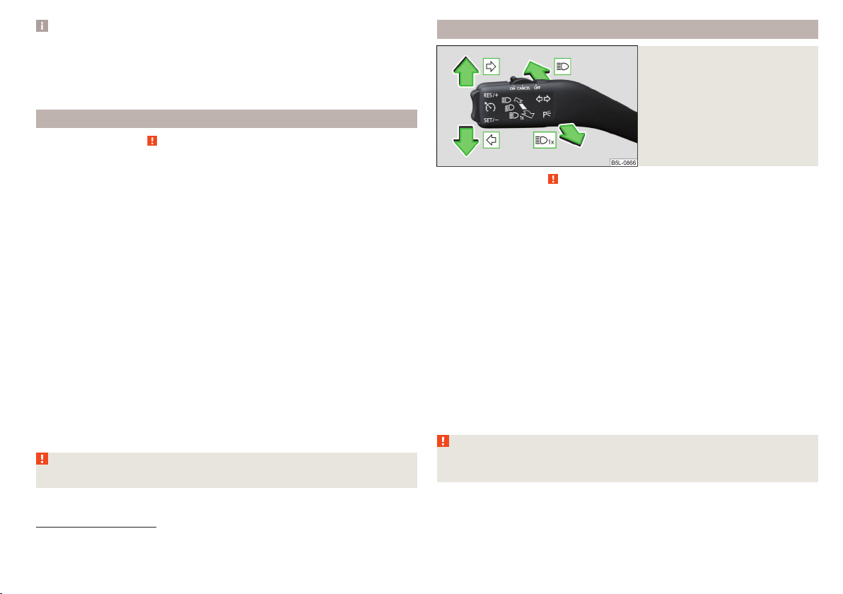
Note
■
If, with a low beam, the ignition is turned off, then the dipped beam will automatically switch off 1) and the parking lights illuminate. The parking lights are
switched off when the ignition key is removed (for vehicles with the KESSY
system, after opening the driver's door).
■
If there is a fault in the light switch, the low beam comes on automatically.
Daylight running lights (DAY LIGHT)
Read and observe on page 58 first.
The daytime running light (hereinafter referred to as "function") lights the
front and rear vehicle area (only valid for some countries).
The daytime running lights are switched on automatically if the following
conditions are met.
The light switch is in the position or
The ignition is switched on.
The function is activated.
Function for vehicles with MAXI DOT display disable / enable
The function menu item
» page 43, Menu item
Disable function for vehicles with segment display
Pull the indicator / main beam lever towards the steering wheel, push down
›
and hold in this position.
Switch on the ignition and hold the lever in the above position until you hear
›
a signal (about 3 s).
Enable function for vehicles with segment display
Pull the indicator / main beam lever towards the steering wheel, push up and
›
hold in this position.
Switch on the ignition and hold the lever in the above position until you hear
›
a signal (about 3 s).
WARNING
Always switch on the low beam when visibility is poor.
Daytime driving light
Settings
.
.
can be deactivated / activated
Turn signal and main beam
Fig. 43
Operating lever: Turn signal and
main beam operation
Read and observe on page 58 first.
Control stalk positions » Fig. 43
Switch on right turn signal
Switch on left turn signal
Switch on main beam (spring-tensioned position)
Switching off main beam / switching on headlamp flasher (spring-loaded
position)
The main beam can only be switched on when the low beam lights are on.
The headlight flasher can be operated even if the ignition is switched off.
The turn signal switches off automatically, depending on the steering angle
after completing the turn.
Comfort signalling
When the operating lever is pressed lightly up or down, the indicator in question flashes three times.
Comfort signalling can be activated / deactivated via the Maxi DOT display in
the
Comfort Signalling
WARNING
Only turn on the main beam or the headlight flasher if other road users will
not be dazzled.
» page 43, Menu item
Settings
menu item.
1)
Does not apply to the position , as long as the conditions are met for the COMING HOME function
» page 61.
Lights and visibility
59

Automatic driving light control
Fig. 44
Light switch: AUTO position
Read and observe on page 58 first.
The light switch is in position
the automatic switch on / off the lights corresponding to the light or weather
conditions (rain) takes place.
Automatic driving light control during rain
The daytime running lights are switched on automatically if the following conditions are met:
The light switch is in the position
The windscreen wipers are on for more than 15 s.
The light turns off automatically about 4 minutes after turning off the wipers.
CAUTION
Poorer visibility is evaluated by a sensor mounted below the windscreen in the
holder of the rear-view mirror. Do not cover the sensor - the system function
can be disrupted.
» Fig. 44 then depending on the equipment
.
Xenon headlight
Read and observe on page 58 first.
The Xenon headlights (hereinafter referred to as just system) use the driving
data to automatically ensure the for the best possible light cone in front of the
vehicle.
The system automatically operates in the following modes: urban, extra urban,
motorway, rain, adjusting the lighting direction of the headlights on the road
illumination on bends.
The system works as long as the light switch is in position
.
WARNING
If there is a system malfunction the headlights are automatically lowered
to the emergency position, which prevents a possible dazzling of oncoming
traffic. This reduces the cone of light in front of the vehicle. Seek help from
a specialist garage.
Fog lights/rear fog light
Fig. 45
Light switch: Switch on fog
lights / rear fog light
Read and observe on page 58 first.
Switching on the fog lights / rear fog lights is possible if the following conditions apply.
The light switch is in the position or » Fig. 45.
To switch on the fog lights, pull the light switch in position 1; the warning
›
light illuminates in the instrument cluster.
To switch on the rear fog light, pull the light switch to position 2, the indi-
›
cator light will light up in the instrument cluster.
If the vehicle is not fitted with fog lights, the rear fog light is switched on by
pulling out the light switch to the only possible setting.
The fog lights/rear fog light are switched off in the reverse order.
Note
While driving with an accessory connected to the trailer socket (e.g. trailer,
bike carrier) only the equipment is illuminated by the fog light. The towing device must be installed at the factory or from the ŠKODA original accessories.
60
Using the system

Fog lights with the CORNER function
Read and observe on page 58 first.
The CORNER function automatically switches on the fog lights on the respective side of the vehicle (e.g. when cornering), if the following conditions are fulfilled.
The turn signal is switched on or the front wheels are turned sharply 1).
The vehicle speed is below 40 km/h.
The low beam is switched on.
The fog lights are not switched on.
The two fog lights are switched on when you shift into the reverse gear.
COMING HOME / LEAVING HOME
Read and observe
The function COMING HOME ensures that the vehicle's environment is illuminated after switching off the ignition and opening the driver's door.
The function LEAVING HOME ensures that the vehicle's environment is illuminated after unlocking the vehicle with the radio remote control unit.
The function switches the light on only if there is poorer visibility and the light
switch is in the position
The functions and settings of the illumination time can be via the MAXI DOT
display in the menu items
and set up» page 43, Menu item
CAUTION
■
Poorer visibility is evaluated by a sensor mounted below the windscreen in
the holder of the rear-view mirror. Do not cover the sensor - the system function can be disrupted.
■
If this option is always enabled, then the battery is heavily loaded.
on page 58 first.
.
Coming Home
or
Settings
Leaving Home
.
activated / deactivated
Hazard warning light system
Fig. 46
Button for hazard warning light
system
Read and observe on page 58 first.
To switch on/off, press the button» Fig. 46.
›
When switched on, the turn signal lights and the warning light buttons all
flash at the same time as the warning lights in the instrument cluster.
The hazard warning light system can also be operated if the ignition is switched off.
If one of the airbags is deployed, the hazard warning light system will switch
on automatically.
When the hazard warning system is on and the indicator light is switched on
(e.g. when turning), the hazard warning lights are switched off temporarily and
only the turn signal flashes on the relevant side of the vehicle.
Parking lights
Read and observe
The side light is provided for lighting of the parked vehicle.
Switching on the side light on one side
Switch off the ignition.
›
Press the control lever all the way into position or until it stops » Fig. 43
›
on page 59.
The parking light is turned on on the relevant side of the vehicle.
on page 58 first.
1)
If the two switch-on variants are conflicting (e.g. if the front wheels are turned to the left and the right
turn signal light is switched on), the turn signal light has the higher priority.
Lights and visibility
61

Switching on the side light on both sides
Switch on the ignition and turn the light switch to position» page 58, the
›
parking lights are turned on.
Switch off the ignition and lock the car.
›
After pulling out the ignition key and opening the driver's door, an audible
warning sounds. After a few seconds or after closing the driver's door, the audible warning is turned off.
CAUTION
■
Turning on the parking light means the battery is heavily loaded.
■
The parking lights may switch off automatically due to a low battery charge.
If the two-sided parking lights are switched on when the ignition is off, the
parking lights will not switch on automatically!
Driving abroad
Read and observe on page 58 first.
When driving in countries with opposing traffic system (traffic on the
left/right), your headlights may dazzle oncoming traffic. Therefore, it is necessary to have the headlights adapted by a specialist garage.
You can adjust the settings of the Xenon headlights for a reverse traffic system in the menu of the MAXI DOT display under the
item» page 43, Menu item
ment is made ahead of the vehicle. When switching on the ignition the warning light flashes for 10 seconds.
Settings
. In this mode, no automatic beam adjust-
Travel mode
menu
Interior lighting
Introduction
This chapter contains information on the following subjects:
Front interior light 62
Interior lighting, rear 63
The inner lighting also works if the ignition is switched off. With the ignition
switched off, the lights will automatically switch off after approximately after
10 minutes.
Front interior light
Fig. 47 Front interior lights: Version 1/version 2
Toggle switch positions
Switching on
Automatic operation (centre position)
Switching off
There is no icon available for the centre position (automatic operation) in Version 2.
Switch on / off (by pressing the relevant switch B) » Fig. 47
Reading lamp left
Reading lamp right
Automatic operation - position
The system is turned on when any of the following is present.
▶
The vehicle is unlocked.
▶
One of the doors or the luggage compartment lid is being opened.
▶
The ignition key is removed.
The system is turned off when any of the following is present.
▶
The vehicle is locked.
▶
The ignition is switched on.
▶
About 30 seconds after all the doors have been closed.
A
» Fig. 47
62
Using the system

Interior lighting, rear
Windscreen and rear window heating
Fig. 48
Interior lights at the rear
Operation (by moving the lens A) » Fig. 48
Switching on
Automatic operation (centre position)
Switching off
1)
Visibility
Introduction
This chapter contains information on the following subjects:
Windscreen and rear window heating
Front sun visors
WARNING
No objects should be attached to the sun visor that could restrict the view
or endanger the vehicle occupants during sudden braking or in a collision.
1)
In this position, the same rules apply to the rear interior light as for the front interior light » page 62,
Front interior light.
Fig. 49 Buttons for rear and front window heating: Manual air condition-
ing / Climatronic
Read and observe
on page 63 first.
The heating for quick defrosting and ventilation of the front /and rear window.
The heating only works when the engine is running.
Buttons for the heating (depending on vehicle equipment) » Fig. 49
Switching the rear window heater on/off
63
64
Switching the windscreen heater on/off
When the heater is switched on, a lamp lights up inside the button.
The heating automatically switches off after 10 minutes.
Note
■
If the on-board voltage decreases, the heating switches off automatically
» page 147, Automatic shutdown of consumers - vehicle battery discharge
protection.
■
If the light is flashing inside the button, the heater will not function due to
low battery.
■
The location of the button can be different depending on the equipment fitted.
Lights and visibility
63

Front sun visors
Fig. 50 Fold down the cover / fold up cover / fold down secondary visor /
make-up mirror and tape
Read and observe on page 63 first.
Operation and description of the sun visor » Fig. 50
1
Swivel cover towards the windscreen
2
Swivel cover towards the door
3
Swivel the assist cover towards the windscreen
A
Make-up mirror with cover (the cover can be pushed in the direction of the
arrow)
B
Tape for storage of small light objects
Windscreen wipers and washers
Introduction
This chapter contains information on the following subjects:
Windscreen wipers and washers
Rear windscreen wipers and washers 65
Headlight cleaning system 66
The windscreen wipers and the wash system only operate if the ignition is
switched on and the bonnet and boot are closed1).
WARNING
Do not use the windscreen washer system at low temperatures, without
heating the windscreen beforehand. The window washer fluid could otherwise freeze on the windscreen and restrict the view to the front.
CAUTION
■
If the windscreen wipers are in rest position, they cannot be folded out from
the windscreen. The wipers must be set to the service position to raise them
off the windscreen » page 166.
■
In cold temperatures and during the winter, check before switching on the
ignition that the wiper blades are not frozen to the windscreen. If the windscreen wipers are switched on when the blades are frozen to the windscreen,
this may damage both the blades and windscreen wiper motor!
■
Carefully separate frozen windscreen wiper blades from the windscreen and
free from snow and ice.
■
Handle the windscreen wipers with care - there is a risk of damage to the
windscreen by the windscreen wiper arms.
■
Do not switch on the ignition when the wiper arm is raised from the windscreen - there is a risk of damage to the bonnet by the wiper arms.
■
If there is an obstacle on the windscreen, the wipers will try to push away
the obstacle five times. The wipers then stop to prevent themselves from being damaged. Only switch the wipers on again after the obstacle has been removed.
65
1)
On vehicles which do not have a contact switch for the bonnet, the windshield wiper and wash system
operates also when the bonnet is opened.
64
Using the system

Note
■
Each time the ignition switches off for the third time, the position of the
windscreen wipers changes. This counteracts an early fatigue of the wiper rubbers.
■
The windscreen washer nozzles for the windscreen are heated when the engine is running and the outside temperature is less than +10 °C.
Windscreen wipers and washers
WARNING
Automatic wiping during rain is only a support. The driver is not released
from the responsibility to set the function of the windscreen wipers manually depending on the visibility conditions.
Note
If the wiping is carried out without interruption, the wiping speed varies depending on the vehicle speed.
Fig. 51
Operating the windscreen wipers
and washer system
Read and observe and on page 64 first.
The lever can be moved to the following positions » Fig. 51
High-speed wiping
Slow-speed wiping
Depending on equipment fitted:
▶
Intermittent wiping
▶
Automatic windscreen wiping in the rain
Wipers and washers off
Single wipe of the windscreen (spring-loaded position)
A
Setting of windscreen wiper interval for the position - by setting the
switch in the direction of the arrow, the windscreen wipers will wipe more
often
Spraying and wiping the windscreen (sprung position)
Spraying and wiping the window
After releasing the operating lever, the wipers will make from 3 to 4 wiper
strokes.
At a speed of more than 2 km/h, the wiper wipes once again 5 seconds after
the last wiper stroke in order to wipe the last drops from the windscreen. This
function can be activated/deactivated by a specialist garage.
Rear windscreen wipers and washers
Fig. 52
Operation of the rear wiper and
washer system
Read and observe and on page 64 first.
The lever can be moved to the following positions » Fig. 52
Spraying and wiping the disc (spring-loaded position) - after releasing the
operating lever the wipers continue for another 2 to 3 strokes.
Rear screen wiping
Wipers and washers off
Automatic rear wiper
If the windscreen wiping is performed without interruption, then the automatic regular intermittent wiping of the rear window takes place.
This mode can be enabled or disabled via the Maxi DOT display in the
er
» page 43, Menu item
Note
The rear window is wiped once automatically if the windscreen wipers are on
when reverse gear is selected.
Settings
menu option.
Rear wip-
Lights and visibility
65

Headlight cleaning system
Read and observe and on page 64 first.
The headlights are cleaned with every first and after every fifth spraying of the
windscreen under the following conditions.
The ignition is switched on.
The low beam is switched on.
The outside temperature is about -12° C to +39° C.
To ensure the correct functioning of the system, even in winter, this needs to
be regularly cleared of snow and ice (e.g. using the de-icing spray).
Rear view mirror
Introduction
This chapter contains information on the following subjects:
Interior mirror dimming
Mirrors
WARNING
Exterior mirrors increase the field of view, however, they make objects appear smaller and further away. Therefore, use the interior mirror whenever
possible, for assessing the distances to the vehicles following behind.
WARNING
■
The mirrors with automatic dimming contain electrolyte fluid which may
leak if the mirror glass is broken - this can irritate skin, eyes and the respiratory system.
■
If your eyes or skin come into contact with the electrolytic fluid, immediately wash the affected area for a few minutes long with a lot of water. If
necessary get medical assistance.
66
Interior mirror dimming
Fig. 53 Interior mirror: manual dimming/auto-darkening
Read and observe
Mirrors with manual dimming » Fig. 53 -
1
Basic mirror position (not darkened)
2
Mirror blackout
67
Mirror with automatic dimming
The mirror dimming » Fig. 53 - is automatically controlled after the engine
start.
When the interior lights are switched on or the reverse gear is engaged, the
mirror moves back into the basic position (not dimmed).
WARNING
■
Attach external devices (e.g. navigation system) not in the vicinity of the
mirror with automatic dimming. The illuminated display of an external device can affect the function of the rear-view mirror -There is a risk of an accident.
■
Automatic mirror dimming only operates correctly if the light striking the
sensor is not affected by other objects. The sensors are located on the
front and back of the mirror.
on page 66 first.
66
Using the system

Mirrors
Fig. 54
Exterior mirror operation
Read and observe on page 66 first.
The exterior mirrors can (depending on vehicle equipment) have a manual or
electric fold-in function, automatic dimming and memory function.
The rotary knob can be moved into the following positions (depending on vehicle equipment)
Adjust the left-hand exterior mirror
Switch off mirror control
Adjust the right-hand exterior mirror
Exterior mirror heater (only operates when the engine is running)
Folding in the mirrors electrically (to fold back, move the rotary knob to an-
other position) »
Setting the mirror area
Move the rotary knob in the direction of arrows » Fig. 54.
›
If the mirror setting fails at any time, the mirrors can be adjusted manually by
pressing on the edge of the mirror area.
Setting the mirror surfaces synchronously
This function allows the simultaneous adjustment of the two mirror areas. This
mode can be enabled or disabled via the Maxi DOT display in the
rors
» page 43, Menu item
Turn the knob for the mirror control to the position for the driver mirror ad-
›
justment.
Adjust the mirror areas to the desired position.
›
Settings
menu item.
Adjust mir-
Manual folding mirrors
The mirror can be manually folded in towards the side window. To put it back
into its original position, it should be folded back from the side window until it
audibly clicks into place.
Folding-in both of the exterior mirrors using the remote control key
Close all windows and hold the button on the remote control key.
›
The exterior mirror is folded back into the driving position when the ignition is
switched on.
Mirror with automatic dimming
The exterior mirror dimming is controlled together with the automatic rearview mirror dimming » page 66.
Memory function for mirror (vehicles with electrically adjustable driver's
seat)
It is possible to save the current setting of the exterior mirror when saving the
driver's seat position with » page 69, Memory Function of the electrically ad-
justable seator » page 70, Memory function of the remote control key.
Tilting the mirror area of the front passenger mirror (vehicles with
electrically adjustable driver's seat)
The front passenger mirror area can be tilted to the stored position to improve
the view to the curb when reversing.
Operating conditions.
The function is activated via the MAXI DOT display in the menu item
down
» page 43, Menu item
The setting of the mirror area has been previously stored » page 69,
Memory Function of the electrically adjustable seat or. » page 70, Memory function of the remote control key.
The reverse gear is engaged.
The knob for the mirror control is in the position for the passenger mirror
adjustment.
The mirror area returns to its initial position after the rotary knob is set to another position or if the speed is greater than 15 km/h.
WARNING
Do not touch the exterior mirror surfaces, if the exterior mirror heating is
switched on - hazard of burning.
Settings
.
Mirror
Lights and visibility
67

CAUTION
■
Never manually fold in/out the electrically folding exterior mirrors - there is a
risk of damage to the mirror!
■
When the mirror is swung by external influences (due to impact during manoeuvring, for example), then first fold-in the mirror by turning the knob and
wait for a loud clapping noise.
Seats and head restraints
Front seats
Introduction
This chapter contains information on the following subjects:
Manual adjustment 68
Electrical adjustment 69
Memory Function of the electrically adjustable seat 69
Memory function of the remote control key 70
Folding front passenger seat 70
Armrest setting 71
WARNING
■
Only adjust the driver's seat when the vehicle is stationary – otherwise
there is a risk of accident!
■
Caution when adjusting the seat! You may suffer injuries or bruises as a
result of adjusting the seat without paying proper attention.
Manual adjustment
Fig. 55
Control elements on the seat
68
Using the system
Read and observe on page 68 first.
The seats can be adjusted by the respective operating element being pulled,
pressed or turned in the direction of the arrows » Fig. 55.
A
Adjusting the seat in the longitudinal direction (after releasing the control
lever, locking must be audible)
B
Adjusting the seat height

C
Adjusting the tilt of the backrest (do not lean on the backrest when adjusting)
D
Setting the extent of the curvature of the lumbar support
Note
After a certain time, play can develop within the adjustment mechanism of the
backrest angle.
Electrical adjustment
Fig. 56 Control elements on the seat
Read and observe on page 68 first.
The seats can be adjusted by the respective operating element being pressed
in the direction of area of the arrow » Fig. 56.
A
seat adjustment
▶
1 - Move in the longitudinal direction
▶
2 - Change in inclination
▶
3 - Change in height
B
Adjusting the seat backrest
▶
4 - Change in inclination
C
Adjusting lumbar support
▶
5 - Change curvature
▶
6 - The degree of curvature change
WARNING
The electric front seat adjustment is functional even with the ignition off.
Therefore, when leaving the vehicle, never leave people who are not completely independent, such as children, unattended in the vehicle - there is a
risk of injury!
Note
If the inclination angle of the seat backrest relative to the seat surface is
greater than 102 °, then it is not possible for safety reasons to save this setting
in the memory of the electrically adjustable seats or the remote control key.
Memory Function of the electrically adjustable seat
Fig. 57
SET button and memory buttons
Read and observe on page 68 first.
Among the memory buttons B on the driver's seat, a setting for the driver´s
seat and exterior mirror position can be saved » Fig. 57.
Storing driver's seat and exterior mirror settings for the forwards drive
Switch on the ignition, adjust the seat and the exterior mirrors.
›
Hold down the
›
sired memory button B at the same time. Storing is confirmed by an acoustic signal.
Storing front passenger´s exterior mirror settings for reversing
Above the MAXI DOT display in the
tion for the mirror on the passenger side must be enabled for reversing
» page 43, Menu item
Turn on the ignition and press the desired memory button B » Fig. 57.
›
Turn the rotary knob for the exterior mirror control to the position for the
›
front passenger mirror area » page 67.
Engage reverse gear.
›
Adjust the front passenger's mirror to the desired position.
›
Disengage reverse gear. The set position of the exterior mirror is stored.
›
A » Fig. 57 button and within 10 seconds press the de-
Settings
Mirror down
.
menu item, the lowering func-
Seats and head restraints
69

Retrieving the saved setting
The retrieval is possible when turned the ignition is switched on and the vehicle speed is less than 5 km/h or when the ignition key is inserted in the ignition lock.
Hold the desired memory button B » Fig. 57 .
›
Stopping the ongoing adjustment
Press any button on the driver's seat or the button on the remote control
›
key.
Note
Every time you save new seat and exterior mirror settings for driving forwards,
you must also save the front passenger mirror setting for reversing again.
Memory function of the remote control key
Read and observe on page 68 first.
Every time the vehicle is locked, the driver´s seat and exterior mirror settings
are saved and assigned to the key with which the vehicle was locked.
After the following unlocking of the vehicle with the same key, the driver´s
seat and exterior mirrors that are saved to this key will be adopted.
Activating the function
Unlock the vehicle with the corresponding remote control key and open the
›
driver door.
Press and hold any memory button B » Fig. 57 on page 69.
›
After the seat has assumed the position stored under this button, at the
›
same time press the button on the remote control key within 10 seconds.
Activation is confirmed by an acoustic signal.
Storing front passenger´s exterior mirror settings for reversing
Above the MAXI DOT display in the
tion for the mirror on the passenger side must be enabled for reversing
» page 43, Menu item
Unlock the vehicle with the remote control key and switch on the ignition.
›
Turn the rotary knob for the exterior mirror control to the position for the
›
front passenger mirror area » page 67.
Engage reverse gear.
›
Adjust the front passenger's mirror to the desired position.
›
Disengage reverse gear. The adjusted position of the exterior mirror is stored
›
in the remote control key memory.
Settings
.
Mirror down
menu item, the lowering func-
Deactivating the function
Unlock the vehicle with the remote control key.
›
Press and hold down the
›
press the button on the remote control key within 10 seconds. Deactivation
is confirmed by an acoustic signal.
Stopping the ongoing adjustment
Press any button on the driver's seat or the button on the remote control
›
key.
A
» Fig. 57 on page 69button. At the same time,
Folding front passenger seat
Fig. 58
Folding the front passenger seat
forward
Read and observe on page 68 first.
The front passenger seat can, depending on specification, be folded forward
into a horizontal position.
To fold the seat down, pull the lever in the direction of arrow 1 and fold
›
down the seat back in the direction of arrow 2 » Fig. 58. The locking mechanism must audibly snap into place.
To
fold back, pull the lever in the direction of arrow 1 pull and fold back the
›
seat back in the direction of arrow 2. The locking mechanism must audibly
snap into place.
Check this by pulling on the seat backrest.
›
WARNING
■
If the seat backrest is folded down, only the seat behind the driver´s seat
can be used to transport passengers.
■
The front passenger airbag should be switched off when transporting objects on the seat which was folded forwards » page 20, Deactivating the
front passenger airbag.
70
Using the system

WARNING (Continued)
■
Do not adjust the seat back while driving - There is a risk of injury and ac-
cidents!
■
When moving the seat backrest, keep limbs out of the area between the
seat and seat backrest – risk of injury!
■
Never transport the following items on the seat backrest when folded
forwards.
■
Objects that could restrict the driver's view.
■
Objects which make it impossible for the driver to control the vehicle
(e.g. if they roll under the pedals, or protrude into the driver's zone).
■
Objects which could lead to injury to passengers (e.g. if accelerating
sharply, braking or changing direction).
Armrest setting
Folding the seat backrest forwards and folding the seat fully forwards 72
Unlock and removing the seat 72
Adjusting seats in crosswise direction 73
Folding back seats 73
Adjusting seats in forward/back direction
Fig. 60
Adjusting seats in forward/back
direction
Fig. 59
Adjust armrest
Read and observe on page 68 first.
To adjust the height, lift the armrest in the direction of the arrowA into one
›
of the six locking positions » Fig. 59.
To close, lift the armrest in the direction of arrow A until the stop and then
›
fold down again.
To longitudinally adjust move the armrest in the direction of arrow B to the
›
desired position.
Rear seats
Introduction
This chapter contains information on the following subjects:
Adjusting seats in forward/back direction
Adjusting the angle of the seat backrest 71
Pull lever Ain the direction of arrow 1and move the seat to the desired po-
›
sition in the direction of arrow 2 » Fig. 60.
Adjusting the angle of the seat backrest
Fig. 61
Adjusting the seat backrest
Pull lever A lever on the bottom in the direction of the arrow 1 pull and set
›
the desired tilt of the seat back in the direction of arrow 2» Fig. 61.
Check for yourself that the seat backrest is engaged by pulling on it.
›
71
Seats and head restraints
71

Folding the seat backrest forwards and folding the seat fully forwards
Safety position of seat belt / folding the seat completely forward
Fig. 62
Fig. 63
Lock forward folded seats
Secure the folded forward seat with the aid of the fixing belt B to a guide rod
›
of the head restraint in the front seat » Fig. 63.
WARNING
■
The seat backs in occupied rear seats must be properly engaged.
■
When transporting objects in the luggage compartment that has been enlarged by folding the backrest forward, ensure the safety of the passengers
transported on the other rear seats.
■
The seat backrests must be securely locked in position so that no objects
in the luggage compartment can slide into the passenger compartment on
sudden braking – There is a risk of injury.
CAUTION
When moving the seat backrest, the seat belts should not be trapped - there is
a risk of damage to the seat belts.
CAUTION
■
Before folding the rear middle seat forward, make sure that the storage com-
partment, the ashtray and the cup holder in the rear part of the centre console
are closed - risk of damage.
■
Only keep the seats in the folded forward position for as long as necessary to
transport cargo - there is a risk of damaging the front seat backrests. The
seats must be folded back once the cargo has been transported.
■
If the outer seat is not in the rear end position when folding forward, damage
can occur to the locking bolts when unlocking the seat.
Folding the seat backrest forwards
Insert the belt buckle Aof the seat belt into the opening in the side pan-
›
el» Fig. 62.
Remove the head restraint from the rear middle seat.
›
Push the outer rear seats towards the rear as far as they will go» Fig. 60 on
›
page 71.
Fold the outer rear seat backrests and the center seat to the stop on the
›
seat surface » Fig. 61 on page 71.
Then pull the lever A » Fig. 61 on page 71 again and push the seat back
›
down until it clicks into place in a lower position.
Folding seats fully forwards and locking them
If the outer rear seat is fully folded forward, push it towards the rear as far as
›
it can go.
Pull the lever B » Fig. 62 in the direction of the arrow 1 and push the seat
›
completely forward in the direction of arrow 2.
72
Using the system
Unlock and removing the seat
Fig. 64
Unlocking the folded forward
seat and carrying handles on the
seat surface
Unlock the folded seat by pressing seat locks» Fig. 62 on page 72 A in the
›
direction of arrow » Fig. 64.
Remove the seat on the carrying handle B or C.
›

Note
The outer seats are not mutually interchangeable. In the rear area the left seat
is marked with the letter L and the right seat with the letter R.
Adjusting seats in crosswise direction
Fig. 65
Locking seats
Remove the middle seat» Fig. 64 on page 72.
›
Fold the outer seat forwards and unlock » Fig. 64 on page 72.
›
Move outer seat on the guide towards the middle of the vehicle up to the
›
stop.
Lock the folded forward seat by pressing the seat locks A in the direction of
›
arrow » Fig. 65.
Folding back into the starting position is accomplished in the reverse order.
Folding back seats
Fig. 66
Folding the seat backrest back
into position
Press the lever in direction of arrow 1 » Fig. 66 and fold back the seat back-
›
rest in the direction of arrow 2. Check this by pulling on the seat backrest.
Headrests
Introduction
This chapter contains information on the following subjects:
Setting the height 73
Removing/installing 74
Note
The middle rear head restraint is only adjustable in two positions.
Setting the height
Fig. 67 Setting the height of the headrest
Grasp the restraint and move upwards in the direction of 1 » Fig. 67.
›
To move the headrest down, press the securing button A in the direction of
›
arrow 2 and hold it down while pressing the headrest in the direction of arrow 3.
If the seat has been removed, first position it on the guide and lock it in place
›
using seat locking A » Fig. 65 on page 73 . Pull the seat upwards to ensure
that the seat is locked correctly.
Fold the seat in the horizontal position until it audibly click in place. Check
›
that the seat can no longer be lifted by pulling it up.
Seats and head restraints
73

Removing/installing
Fig. 68 Removing/installing the headrest
To
remove the headrest, pull it out of the seat backrest up to the latch.
›
Press locking button A in the direction of arrow 1, and pull out the head re-
›
straint in the direction of arrow 2 » Fig. 68.
To insert the headrest, push the headrest into the seat backrest in the direc-
›
tion of arrow 3 until the locking button clicks into place.
Front seat heating
Fig. 69
Buttons for heating the front
seats
The seat backrests and seats can be heated electrically.
Seat heating buttons » Fig. 69
Left seat heating
Right seat heating
To turn on the heating with maximum heat , press the key or button.
›
By repeatedly pressing the button, the heat is turned down until it is completely switched off. The level of the seat heating is indicated by the number
of illuminated warning lights in the switch.
The seat heating only operates when the engine is running.
WARNING
If you are sensitive to pain and/or temperature, e.g. through medication,
paralysis or because of chronic illness (e.g. diabetes), we recommend not to
use the seat heating. If the seat heating is used, we recommend to make
regular breaks in your journey when driving long distances, so that the
body can recuperate from the stress of the journey. Please consult your
doctor, who can evaluate your specific condition.
CAUTION
The following instructions should be observed to avoid damage to the seats.
■
Do not kneel on the seats or otherwise apply concentrated pressure to them.
■
Do not switch on the heating for unoccupied seats.
■
Do not switch on the heating for seats which have objects on them (e.g. a
child seat, bag or similar).
■
Do not switch on the heating for seats which have seat covers or protective
covers on them.
Note
If the on-board voltage decreases, the seat heating switches off automatically
» page 147, Automatic shutdown of consumers - vehicle battery discharge
protection.
74
Using the system

Useful features
Interior fittings
Introduction
This chapter contains information on the following subjects:
Ticket holder 75
Storage compartment on the dash panel 76
stowage compartments in the doors 76
Storage compartment in the front centre console 76
USB and AUX input 77
Cup holders 77
Cigarette lighter 78
Ashtray 78
12-volt socket 79
Waste container 80
Multimedia holder 80
Storage compartment under the front arm rest 81
storage net in the front centre console 81
Glasses compartment 81
Storage compartment on the front passenger side 82
Storage compartment for umbrella 82
Clothes hook 82
Storage pockets on the backs of the front seats 83
Storage compartment in the rear centre console 83
Folding table on the front seat backrest 83
Folding table on the middle seat backrest 84
Removable through-loading bag 84
WARNING
■
Do not place anything on the dashboard. These objects might slide or fall
down when driving and may distract you from concentrating on the traffic –
risk of accident!
■
Make sure that while driving no objects can enter the driver's footwell There is a risk of an accident!
WARNING (Continued)
■
Do not carry any objects on the front passenger seat except objects de-
signed for this purpose (e.g. child seats) – risk of accident!
■
No objects should be placed in the storage compartments nor in the
drinks holders; the vehicle occupants could be endangered if there is sudden braking or the vehicle collides with something.
■
For safety reasons, lockable storage compartments should be closed
while driving - there is a risk of injury from the opened lid or through the
loose objects in the compartment.
■
Make sure no objects protrude from the storage compartments - There is
a risk of injury!
■
Do not exceed the permissible loads for the storage compartments, pockets and nets - There is a risk of injury and a risk of damage to the compartments, pockets and nets!
■
Ash, cigarettes, cigars and the like should only be stored in the ashtray There is a risk of fire/burns!
■
The storage compartments, multimedia holder and waste container are
not a substitute for the ashtray and must not be used for such purposes –
There is a risk of fire!
CAUTION
Do not place any large or sharp objects in the storage compartments, pockets
and nets -There is a risk of damage to the compartments, pockets and nets.
Ticket holder
Fig. 70
Ticket holder
Read and observe and on page 75 first.
The ticket holder» Fig. 70 is provided for the holding and displaying e.g. car
park tickets.
Useful features
75

Storage compartment on the dash panel
Fig. 71
Opening the storage compartment
Read and observe and on page 75 first.
To the Open press the button » Fig. 71, the cover opens in the direction of
›
arrow.
To close, swing the lid against the direction of the arrow until it audibly clicks
›
into place.
Certain models do not have a storage compartment lid.
CAUTION
Do not put any heat-sensitive objects in the storage compartment - in the
event of high temperatures there is risk of damage.
Read and observe and on page 75 first.
Storage compartments » Fig. 72
A
Storage compartment
B
Bottle holder with a capacity of max. 1 l
C
Bottle holder with a capacity of max. 0.5 l
WARNING
The storage compartment A » Fig. 72 is to be used exclusively for storing
objects which do not stick out - There is a risk of restricting the effectiveness of the side airbags.
Storage compartment in the front centre console
Fig. 73
Non-lockable compartment
stowage compartments in the doors
Fig. 72 Storage compartments: in the front door/in the rear door
76
Using the system
Read and observe and on page 75 first.
The storage compartment is in the front of the centre console » Fig. 73.

USB and AUX input
Cup holders
Fig. 74 AUX input: underneath the armrest / above the storage compartment
Fig. 75
USB input
Read and observe and on page 75 first.
Depending on equipment fitted, the AUX input is located below the armrest
» Fig. 74 - or above the storage compartment » Fig. 74 - .
The USB input (marked with
ment » Fig. 75.
Information on use » Owner's Manual infotainment or » The Radio Owner's
Manual.
and ) is located above the storage compart-
Fig. 76 Cup holders: in the front centre console / on the folding table in
the centre backrest
Fig. 77 Cup holders in the rear centre console: Open / Adjust size
Read and observe
In the cup holders A and B two drinks containers can be placed in each
» Fig. 76.
Cup holderD in rear centre console
To Open Press the holder in the area C » Fig. 77. The holder slides out.
›
Pull the holder up to the stop in the arrow direction 1 resize by moving the
›
plate E in direction of arrow 2.
To close, push in the holder against the direction of arrow 1.
›
A 1.5 litre bottle (max. capacity) can be stored in the holder D.
and on page 75 first.
Useful features
77

WARNING
■
Do not use any cups or beakers which are made of brittle material (e.g.
glass, porcelain). This could lead to injuries in the event of an accident.
■
Never put hot beverage containers in the cup holder. If the vehicle moves,
they may spill – There is a risk of scalding!
CAUTION
■
Do not leave open beverage containers in the cup holders during the journey.
There is a risk of spilling e.g. when braking which may cause damage to the
electrical components or seat upholstery.
■
Before folding the rear centre seat, the holder D » Fig. 77 must be closed otherwise there is risk of damage.
Cigarette lighter
Fig. 78
Cigarette lighter
Read and observe and on page 75 first.
To use the lighter, push it in as far as the stop and wait until the glowing
›
lighter clicks out again » Fig. 78.
Take out the glowing lighter instantly, use it and insert it back into the sock-
›
et.
WARNING
■
The cigarette lighter also works if the ignition is switched off. When leaving the vehicle, never leave people who are not completely independent,
such as children, unattended in the vehicle - there is a risk of burning, fire
or damage to the vehicle interior.
■
Be careful when using the cigarette lighter - There is a risk of burns.
Note
The cigarette lighter socket can also be used as a 12 volt socket.
Ashtray
Fig. 79 Removing and opening front ashtray and / Low centre console:
Open rear ashtray/ remove rear ashtray
Fig. 80 High centre console: Open rear ashtray / Removing rear ashtray
insert
Read and observe
The ashtray can be used for ash, cigarettes, cigars and the like.
Removable front ashtray
Remove the ashtray in the direction of the arrow A » Fig. 79.
›
Insertion takes place in reverse order.
To the Openturn the ashtray cover in the direction of arrow B.
›
Closing takes place in reverse order.
and on page 75 first.
78
Using the system

Rear ashtray - low centre console
To open, grasp the lid on the edgeC and fold in the direction of arrow
›
until the stop » Fig. 79.
To remove, grasp the ashtray at the handle D and remove in direction of ar-
›
row 2.
To use Insert the ashtray in the console away from arrow 2 and push in.
›
Rear ashtray - high centre console
To open, press on the lid of the glasses compartment in area E. The ashtray
›
opens out in the direction of the arrow 1» Fig. 80.
To remove the ashtray insert press the lid gently1 up to the stop.
›
Grasp the ashtray insert in the area of arrow and remove it in the direction of
›
arrow 2.
To the insert the ashtray insert push in the insert away from the arrow
›
and push in.
WARNING
Never place hot or flammable objects in the ashtray – risk of fire!
CAUTION
The ashtray in the higher central console must be closed before folding forward the rear middle seat - Otherwise there is a risk of damage.
12-volt socket
Connect the plug for the electrical appliance to the socket.
1
2
›
WARNING
■
Do not place anything on the dashboard. These objects might slide or fall
down when driving and may distract you from concentrating on the traffic –
There is a risk of accident!
■
Make sure that while driving no objects can enter the driver's footwell There is a risk of an accident!
■
Stow all devices safely during the journey to prevent them from being
thrown around the interior in the event of a sudden braking manoeuvre or
an accident – There is a risk of death!
■
The devices may warm up during operation – There is a risk of injury or
fire!
■
Improper use of the power sockets and the electrical accessories can
cause fires, burns and other serious injuries.
■
The socket also works if the ignition is switched off. When leaving the vehicle, never leave persons who are not completely independent, such as
children, unattended in the vehicle.
CAUTION
■
The sockets can only be used for the connection of approved electrical ac-
cessories with a total power consumption of up to 120 watts - otherwise the
electrical system of the vehicle may be damaged.
■
Connecting appliances when the engine is not running will drain the battery
of the vehicle!
■
Before switching the ignition on / off or before starting the engine, switch
off the devices which are connected to the sockets - there is a risk of damage
to the equipment due to voltage fluctuations.
Fig. 81 Cover the 12-volt socket: in the front centre console / in the lug-
gage compartment
Read and observe and on page 75 first.
To use, remove the cover of the socket » Fig. 81 - or open the cover of the
›
socket » Fig. 81 - .
Useful features
79

Waste container
Fig. 82 Waste container: Inserting and moving/opening
Fig. 83 Replacing bags
Read and observe and on page 75 first.
The waste container can be inserted into the slot in the door.
Insert waste container
Position the waste container at the front edge of the slot.
›
Push the waste container to the back in the direction of the arrow
›
» Fig. 82.
Push the waste container as required in the direction of arrow B.
›
Remove the waste container
Remove the waste container in the opposite direction to the arrow
›
» Fig. 82.
Open/close waste container
Lift the lid in the direction of arrow C » Fig. 82.
›
Closing takes place in reverse order.
Replace bags
Remove the waste container from the slot.
›
Press the two locking lugs on the frame in the direction of arrow 1» Fig. 83.
›
Pull the bag together with the frame down in the direction of arrow 2.
›
Remove the bag from the frame.
›
Pull the new bag through the frame and pull it over the frame in the direction
›
of arrow 3.
Place the bag with the frame in the direction of arrow 4 into the container
›
body, so that the two lugs engage audibly on the frame.
Note
We recommend that you use 20x30 cm bags.
Multimedia holder
Fig. 84
Multimedia holder
Read and observe and on page 75 first.
Multimedia holder » Fig. 84
A
Storage compartment for storing two coins
B
Storage compartment for storing the vehicle key
C
A
A
Storage compartment for storing a mobile phone
80
Using the system
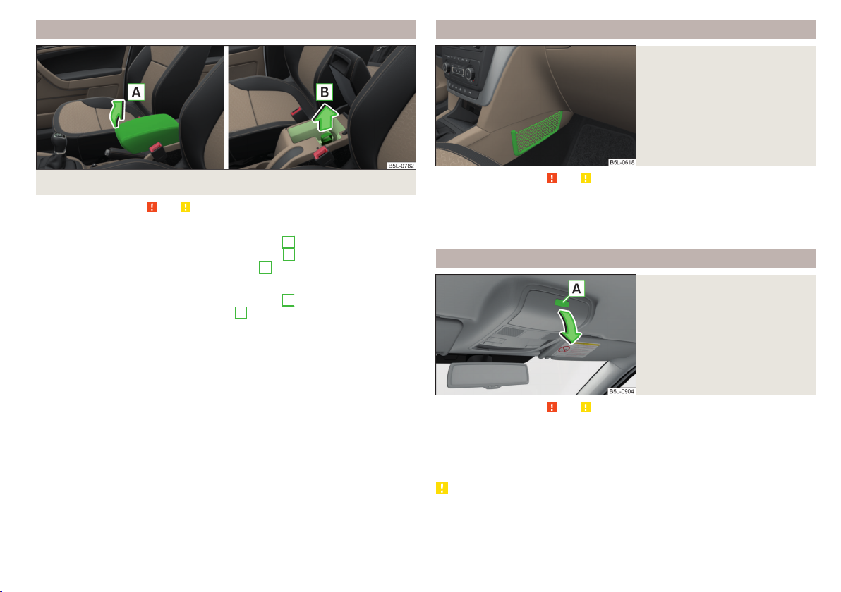
Storage compartment under the front arm rest
Fig. 85 Open storage compartment / open air supply
Read and observe
Storage compartment
To open, lift the armrest in the direction of arrow A» Fig. 85.
›
To close, lift the armrest in the direction of arrow A until the stop and then
›
fold down against the direction of the arrow A.
Air supply
To open, pull the handle in the direction of arrow B » Fig. 85.
›
To close, turn the dial away from arrow B until the stop.
›
When the air inlet is opened, the air flows into the storage compartment with
a temperature corresponding to the control dial settings on the A/C unit, depending on the outer climate conditions.
The air inlet in the storage compartment is connected to position through
adjustment of the control dial for air distribution. This setting causes the maximum amount of air to flow into the storage compartment (depending on the
rotary regulator position for the fan).
and on page 75 first.
storage net in the front centre console
Fig. 86
Storage net
Read and observe and on page 75 first.
The storage nets» Fig. 86 are intended for the storage of e.g. maps, magazines, etc.
The maximum permissible load of the net is 0.5 kg.
Glasses compartment
Fig. 87
Opening the glasses storage box
Read and observe and on page 75 first.
To open, press the -- button. The compartment folds in the direction of the
›
arrow » Fig. 87.
To close, swivel the compartment against the direction of the arrow until it
›
audibly clicks into place.
CAUTION
■
Do not put any heat-sensitive objects in the glasses storage box – there is
risk of damage at high temperatures.
■
The compartment must be closed before leaving and locking the vehicle –
There is a risk of impairment to the functions of the anti-theft alarm system.
Useful features
81

Storage compartment on the front passenger side
Fig. 88 Open storage compartment / open air supply
Read and observe
Storage compartment
To open, press the -- button. The cover folds in the arrow direction» Fig. 88.
›
To close, swing the lid against the direction of the arrow until it audibly clicks
›
into place.
Air supply
To Open pull the lever B in the direction of the arrow to the stop » Fig. 88.
›
To close, turn the lever against the direction of the arrow until it stops.
›
The temperature of the storage compartment supplied with air is dependent
on the setting in the air conditioning.
Note
A pen holder is provided in the stowage compartment.
and on page 75 first.
Storage compartment for umbrella
Fig. 89
Opening the storage compartment
Read and observe and on page 75 first.
The storage compartment under the passenger seat is used for storing an umbrella.
To open, pull the handle in direction of arrow 1 pull and open the compart-
›
ment in the direction of arrow 2» Fig. 89.
To close, screw in the lid in the opposite direction of arrow 2 until it audibly
›
clicks into place.
CAUTION
Never store a wet umbrella in the storage compartment - there is a risk of
damage to the umbrella.
Note
We recommend that you use the umbrella from the ŠKODA Original Accessories.
Clothes hook
Fig. 90
Clothes hooks
Read and observe and on page 75 first.
The clothes hooks are located on the middle door pillars of the vehicle and on
the handle of the headliner above each of the rear doors » Fig. 90.
The maximum permissible load of each of the hooks is 2 kg.
82
Using the system

WARNING
■
Never leave any heavy or sharp-edged objects in the pockets of the items
of clothing hung up - There is a risk of injury.
■
Do not use hangers to hang up the clothes - there is a risk of restricting
the effectiveness of head airbags and a danger of injury from the hanger.
■
Make sure that any clothes hanging from the hooks do not impede your
vision.
To close, swivel the compartment against the direction of the arrow.
›
CAUTION
Before folding forward the rear centre seat, the storage compartment must be
closed - there is a risk of damage to the storage compartment.
Folding table on the front seat backrest
Storage pockets on the backs of the front seats
Fig. 91
Map pockets
Read and observe and on page 75 first.
The storage pockets » Fig. 91 are intended for the storage of maps, magazines,
etc.
Storage compartment in the rear centre console
Fig. 92
Opening the storage compartment
Read and observe and on page 75 first.
To openPull the top edge and open the compartment in the arrow direc-
›
tion» Fig. 92.
Fig. 93
Fold down the folding table
Read and observe and on page 75 first.
To Unfold Raise the table in the direction of the arrow in the horizontal posi-
›
tion » Fig. 93.
Fold the table back into the vertical position by push the table away from the
›
arrow.
The maximum permissible load for the table is 10 kg.
WARNING
■
The table must not be in the horizontal position while driving - risk of injury.
■
Do not use any cups or beakers which are made of brittle material (e.g.
glass, porcelain). This could lead to injuries in the event of an accident.
■
Never put hot beverage containers in the table cup holder. If the vehicle
moves, they may spill – There is a risk of scalding!
Useful features
83

Folding table on the middle seat backrest
Fig. 94
Middle seat backrest already folded forward
Read and observe and on page 75 first.
After folding forwards,the centre seat backrest can be used as an armrest or
table with cup holders » Fig. 94.
CAUTION
If the middle rear seat backrest should be folded forward for lengthy periods,
then make sure that the belt locks are not located below it - this can warp the
upholstery or fabric.
Place the empty through-loading bag in such a way that the end of the bag
›
with the zip is in the boot.
Push the skis and poles with the tips backwards into the through-loading
›
bag and secure the bag.
Securing through-loading bag and skis
Pull the securing belt with both lock tongues out of the pocket of the
›
through-loading bag.
Insert the lock tongues A » Fig. 95 in the belt locks of the rear middle seat
›
belt C, first on the one side and then on the other side.
Place the securing belt in the middle of the skis between the heel and the tip
›
of the bindings and pull the securing belt tight at the free end of the belt B.
WARNING
■
The total weight of the skis which are transported must not exceed 10 kg.
■
Always stow and secure the skis and the bag securely - otherwise there is
a risk of injury or accident!
CAUTION
Never fold and stow the through-loading bag when it is wet -There is a risk of
damaging the through-loading bag.
Removable through-loading bag
Fig. 95
Securing the removable throughloading bag
Read and observe and on page 75 first.
The removable through-loading bag (hereinafter referred to as through-loading bag) is used exclusively for transporting skis (max. 2 pairs).
Loading through-loading bag and skis
Fold the middle rear seat backrest forwards until it rests on the seat
›
» page 71.
84
Using the system
Tablet holder
Introduction
This chapter contains information on the following subjects:
Attaching the rear headrests 85
Handle holder 85
External devices (e.g. tablet, smartphone, etc.) measuring min. 122 mm and
max. 195 mm can be secured in the support.
The maximum permissible load of the compartment is 750 g.
CAUTION
Never exceed the maximum permissible load of the holder - there is a risk of
damage or functional impairment.

Attaching the rear headrests
Handle holder
Fig. 96 Inserting: Adapter / Holder
Fig. 97 Removing: Holder / Adapter
Read and observe on page 84 first.
To insert, attach the opened adapter to the guide rods of the front headrest
›
and clip in the direction of arrow 1 » Fig. 96 » .
Clip the holder in the direction of arrow 2 into the adapter.
›
To remove, pull on the securing tab A in direction of arrow 3 and take the
›
holder in direction of arrow 4 out of the adapter » Fig. 97.
Press the adapter and remove from the guide rods of the headrest in the di-
›
rection of arrow 5.
WARNING
Carefully clip in the adapter - there is a risk of injuring your finger.
Fig. 98 Tilt and rotate holder
Fig. 99
Adjust holder size
Read and observe on page 84 first.
The holder may be --tipped by 30° in the direction of the arrow 1 and --turned
by 360° in the direction of arrow 2» Fig. 98.
To adjust the holder size, pull out the securing tab A in the direction of ar-
›
row 3 and push the part B in the direction of arrow 4 to the desired position » Fig. 99.
Useful features
85

Transport of cargo
Luggage Storage and Transport
Introduction
This chapter contains information on the following subjects:
Fastening elements 87
Fixing nets 87
Multifunction pocket 87
Fastening bar with sliding hook 88
Flexible storage compartment 88
Floor covering on both sides 88
Luggage compartment cover 89
Net partition 89
Storage compartments 90
Removable storage box 90
Removable lamp 90
Class N1 vehicles 91
When transporting heavy objects, the driving characteristics change due to the
shift in the centre of gravity. The speed and style of driving must be adjusted
accordingly.
When transporting cargo, the following instructions must be adhered to
▶
Distribute the load evenly in the luggage compartment and secure it with
suitable lashing straps to the lashing eyes or fixing nets so that they cannot
slip.
▶
Place heavy objects as far forward as possible.
▶
Tyre pressure should be adjusted for the load.
In the event of an accident, even small and light objects gain so much kinetic
energy that they can cause severe injuries.
The magnitude of the kinetic energy is dependent on the speed at which the
vehicle is travelling and the weight of the object.
WARNING
■
Never exceed the maximum permissible load of the respective fasteners,
nets, hooks etc. If heavy objects have not been suitably secured, there is a
risk of injury!
■
Do not exceed the permissible axle loads and permissible gross weight of
the vehicle – There is a risk of an accident!
■
An unsecured dirt or improperly attached load could slip during a sudden
manoeuvre or in an accident - There is a risk of injury!
■
Loose cargo could hit a deployed airbag and injure occupants – danger of
death!
■
When transporting loads in the luggage compartment that has been enlarged by folding one of the rear seats forward, care should be taken to ensure the safety of passengers transported on the other rear seat.
CAUTION
■
Never exceed the maximum permissible load of the respective fasteners,
nets, hooks, etc. - these could be damaged.
■
Please ensure that the heating elements for the rear window heater are not
damaged as a result of abrasive objects.
■
Do not place sharp objects in the nets and storage compartments in the lug-
gage compartment - there is a risk of damage to the net as well as the compartments.
■
Put the items in the storage compartments carefully and do not put point-
shaped objects - there is a risk of damage to the compartments.
86
Using the system

Fastening elements
Read and observe and on page 86 first.
Fastening examples for nets » Fig. 101
A
Horizontal pocket
B
Floor net
C
Vertical pocket
The maximum permissible load of each of the nets is 1.5 kg.
Multifunction pocket
Fig. 100 Fasteners: Version 1/version 2
Read and observe
The fasteners are located on both sides of the luggage compartment.
Overview of the fastening elements » Fig. 100
A
Lashing eyes for securing items of luggage, fastening nets and multifunction pocket
B
Fastening strip with integrated hook for attaching fastening nets and multifunction pocket
C
Lashing eyes only for fastening fixing nets
The maximum static load of the individual lashing eyes A is 350 kg C is 150
kg.
and on page 86 first.
Fixing nets
Fig. 101
Fastening examples for nets
Fig. 102
Securing the multifunction pocket
Read and observe and on page 86 first.
The pocket » Fig. 102 can be secured to the fastening elements Aand
B
» Fig. 100 on page 87.
The maximum permissible load for the bag attached to the fastening element
is 3 kg.
CAUTION
In vehicles with a variable loading floor, it is not possible to attach the bag to
the fastening elements.
Transport of cargo
87

Fastening bar with sliding hook
Fig. 103 Sliding hook onto the mounting bar / removing hook
Read and observe
A fastening bar is located on both sides of the luggage compartment with two
moveable hooks each, in order to attach small items of luggage, such as bags,
etc.
The maximum permissible load of each of the hooks is 7.5 kg.
Moving the hook
Fold up the hook in direction of arrow 1 » Fig. 103 until an angle of approx.
›
45° is reached.
Move the hook in the direction of the arrow 2 into the desired position and
›
fold down the hook as far as the stop in direction of arrow 3.
Removing hooks
The hook can be removed only in the rear region of the attachment bar.
Fold the hook upwards in direction of arrow 4 » Fig. 103 until it disengages,
›
and remove in the direction of arrow 5.
Inserting hook
Position the hook on the fastening strip in a vertical position in direction of
›
arrow 5 » Fig. 103 and lightly press it on.
Fold the hook up to the stop away from arrow 4 until it locks.
›
and on page 86 first.
Flexible storage compartment
Fig. 104
Flexible storage compartment
Read and observe and on page 86 first.
The flexible storage compartment can be installed on the right-hand side of
the boot » Fig. 104.
The storage compartment is designed for storing small objects with a maximum total weight of 8 kg.
To use,insert the two ends of the storage compartment into the openings in
›
the side trim of the luggage compartment and push the shelf down to lock.
To remove grasp the storage compartment on both top edges, press the up-
›
per corners inwards and release the storage compartment by pulling upwards.
Remove the storage compartment by pulling towards you.
›
CAUTION
The flexible storage compartment cannot be installed on vehicles with the variable loading floor.
Floor covering on both sides
Read and observe and on page 86 first.
You can fit a double-sided floor covering in the luggage compartment. One
side is made of fabric, the other side is washable (suitable for transporting wet
or dirty items).
88
Using the system

Luggage compartment cover
Fig. 105 Remove the luggage compartment cover
Read and observe
If the support straps A » Fig. 105 are attached to the boot lid, then opening
the lid will raise the boot lid cover (hereafter referred to as cover).
Removing
Partially fold the rear seat backrests forward » page 71, Adjusting the angle
›
of the seat backrest.
On both sides of the boot lid, unhook the straps A in the direction of arrow
›
1
» Fig. 105.
Place the cover in the horizontal position.
›
Press on the two sides to the underside of the cover in the region of the
›
studsC in the direction of arrow 2.
Fold the slackened front part of the boot cover over the head restraints of
›
the rear seats.
Slightly tilt the cover and remove.
›
Fitting
Place the cover on the contact surfaces of the side trim panel.
›
Position the mounts on the cover B onto the side trim panel via pins
›
» Fig. 105.
Press on the two sides to the upper side of the cover in the region of the
›
studs C.
The fixture B must lock into place of the studs C on both sides of the luggage compartment.
Unhook the straps A on both sides of the boot lid.
›
and on page 86 first.
C
WARNING
Do not place any objects on the cover during the trip - there is a risk of injury if braking suddenly or colliding!
Net partition
Fig. 106
The net partition can either fitted behind the rear seats or behind the front
seats.
Fitting/removing behind the rear seats
Remove the luggage compartment cover » page 89, Luggage compartment
›
cover.
Remove the net partition from the bag.
›
Unfold both parts of the cross rod until they are heard to engage.
›
First insert the rod into the mount B » Fig. 106 on one side and push it for-
›
wards. In the same way, insert the cross rod into the mount B on the other
side of the vehicle.
Hang the carabines C at the belt ends into the lashing eyes behind the rear
›
seats.
Pull the belts through the tensioning clasp.
›
Removingis carried out in the reverse order.
Packing the net partition
Press the red button of the joint A » Fig. 106. The joint is undone.
›
Net partition behind the rear seats
Read and observe and on page 86 first.
Transport of cargo
89

Put the net partition folded together in the bag and close it.
›
Attach the bag with the aid of the plastic carabines to the eyes on the left
›
and right boot trim panel.
Installing and removing the net partition behind the rear seats with variable
loading floor is carried out in the same way as behind the rear seats without
variable loading floor. Use the lower fixing eyelets on the carrier rails in order
to attach the carabines.
Installing and removing the net partition behind the front seats is carried out
in the same way as behind the rear seats. Use the fixing eyelets on the rear of
the front seats to attach the carabines. To enlarge the boot, the rear seats can
be removed » page 72.
The opening D » Fig. 106 in the net partition is for passing the three-point
seat belt » page 15 through.
Storage compartments
Removable storage box
Fig. 108
Storage box
Read and observe and on page 86 first.
The storage box » Fig. 108 is placed under the variable loading floor and can be
taken out.
There is a storage space for the vehicle tool kit under the storage box
» page 155, Vehicle tool kit.
WARNING
The removable storage box must be located under the variable loading
floor for the safe use of the variable loading floor.
Removable lamp
Fig. 107
The cover for the storage compartment A » Fig. 107 can be removed, thus enlarging the boot.
Grasp the top part of the cover A and carefully remove it in the direction of
›
the arrow.
The storage compartment Ais suitable for stowing small objects weighing up
to 1.5 kg in total, and the compartment B up to 0.5 kg.
90
Storage compartment on the left / right
Read and observe and on page 86 first.
Using the system
Fig. 109
Removable lamp

Fig. 110
Removable light: Removing / Inserting
Read and observe and on page 86 first.
The light is located on the right side of the luggage compartment and is used
to light the luggage compartment or as a portable light.
The lamp is fitted with magnets. As a result, this can, for example, be fitted to
the vehicle body.
Description of the light » Fig. 109
A
Button to turn on / off the light
B
Part that lights up when the lamp is in the mount
C
Part that lights up when the lamp is not in the mount
If the light is in the mount, this will illuminate when the boot lid is opened.
To remove, hold the light in the area D and swivel in the direction of arrow
›
1
» Fig. 110.
To switch on the removed light, press button A» Fig. 109. Pressing the light
›
again will switched it off.
To insert, first of all insert the light with the rear part E into the mount
›
» Fig. 110 and then push the light in the direction of arrow 2 until it audibly
clicks into place.
If the light is not switched off and is correctly inserted in the mount, the LED
diodes in the front part of the light C» Fig. 109 are automatically switched off.
If the lamp is not correctly inserted into the holder, this does not light up when
the boot lid is opened and the rechargeable batteries are not charged.
Lamp charges
The lamp is supplied by three rechargeable type NiMH AAA batteries. The batteries are charged continuously with the engine running (to fully charge the
battery takes approximately 3 hours).
Replace batteries » page 164.
CAUTION
The light is not waterproof, so it must be protected from humidity - otherwise
there is risk of damage.
Class N1 vehicles
Read and observe and on page 86 first.
On class N1 vehicles, which are not fitted with a protective grille, a lashing set
which complies with the standard EN 12195 (1 - 4) must be used for fastening
the load.
Proper functioning of the electrical installation is essential for safe vehicle operation. It is important to ensure that the electrical installation is not damaged
during the adjustment process or when the storage area is being loaded and
unloaded.
Variable loading floor in the luggage compartment (Estate)
Introduction
This chapter contains information on the following subjects:
Removing/fitting variable loading floor
Secure the variable loading floor in the raised position 92
Removing/installing the carrier rails 92
Using the variable loading floor with a spare wheel 92
The variable loading floor makes it easier to handle bulky goods and creates an
even surface when the rear seat backrests are folded forward.
The maximum permissible load of the variable loading floor is 75 kg.
92
Transport of cargo
91

Removing/fitting variable loading floor
Removing/installing the carrier rails
Fig. 111 Fold up / removal variable loading floor
To
fold together, grasp the variable loading floor on handle A and lift in the
›
direction of arrow 1» Fig. 111.
Fold up the variable loading floor in direction of arrow 2.
›
Pull on both sides of the locking levers in direction of arrow 3.
›
Remove the variable loading floor in direction of arrow 4.
›
Insertion takes place in reverse order.
Secure the variable loading floor in the raised position
Fig. 112
Secured loading floor in the
raised position
Fold up the hooks on the fastening strip in direction of arrow 1 » Fig. 103 on
›
page 88.
Fold up the variable loading floor behind the rear back backrests.
›
Fold down the hooks in direction of arrow 3 » Fig. 103 on page 88 as far as
›
the stop.
Support the variable loading floor on the hooks folded downwards » Fig. 112.
›
92
Using the system
Fig. 113 Slacken check points/remove carrier rails
Removing
Undo the securing points B » Fig. 113 on the carrier rails using the vehicle
›
key or a flat screwdriver.
Hold the carrier rail A in the front area and remove by pulling in the direction
›
of arrow 1.
Hold the carrier rail A in the rear area and loosen and remove by pulling in
›
the direction of arrow 2.
Fitting
Position the carrier rails on the sides of the boot.
›
Press the two securing points B » Fig. 113 on each carrier rail to the stop.
›
Check the attachment of the carrier rails by pulling it.
›
Using the variable loading floor with a spare wheel
Fig. 114 Fold up the side panels of the variable loading floor / space under
the variable loading floor

The sides of the variable loading floor can be folded in the direction of arrow
» Fig. 114 - .
The room under the variable loading floor » Fig. 114 - can be used to stow
the load.
Transportation on the roof rack
Roof load
The maximum permitted weight of the load incl. carriers is 100 kg.
WARNING
The following instructions must be observed to aid road safety when transporting cargo on the roof rack.
■
Always distribute the load on the roof rack evenly and secure properly
with suitable lashing straps or tensioning straps.
■
When transporting heavy objects or objects which take up a large area on
the roof rack system, the handling of the car may change as a result of the
displacement of the centre of gravity. The style of driving and speed must
therefore be adapted to the current circumstances.
■
The permissible roof load, permissible axle loads and permissible total vehicle weight must not be exceeded under any circumstances – risk of accident!
CAUTION
■
Make sure that the sliding / tilting roof or the boot lid does not collide with
the roof load when opened.
■
Ensure the roof aerial is not impaired by the load being transported.
Note
We recommend that you use a roof rack from ŠKODA Original Accessories.
Heating and ventilation
Heating, manual air conditioning system, Climatronic
Introduction
This chapter contains information on the following subjects:
Heating and manual air conditioning 94
Climatronic (automatic air conditioning) 94
Climatronic - automatic operation 95
Air distribution control 96
Air outlet vents 96
The heater heats and ventilates the vehicle interior. The air conditioning system also cools and dehumidifies the vehicle interior.
The heating effect is dependent upon the coolant temperature, thus full heat
output only occurs when the engine has reached its operating temperature.
The cooling system works under the following conditions.
The cooling system is switched on.
The engine is running.
The outside temperature is above 2 °C.
The blower is switched on.
When the cooling system is switched on, it prevents misting of the windscreen
and windows.
It is possible to boost the effectiveness of the cooling system by briefly activating the air recirculation system» page 96.
Health protection
To reduce health risks (e.g. common colds), the following instructions for the
use of the cooling system are to be observed.
▶
The difference between the outside temperature and the inside temperature
should not be greater than 5 °C.
▶
The cooling system should be turned off about 10 minutes before the end of
the journey.
▶
Once a year, a disinfection of the air conditioner is to be carried out by a specialist company.
Heating and ventilation
93

WARNING
■
The blower should always be on to prevent the windows from misting.
Otherwise there is a risk of accident.
■
Under certain circumstances, air at a temperature of about 5 °C can flow
out of the vents when the cooling system is switched on.
Note
■
The air inlet in front of the windscreen must be free of e.g. ice, snow or
leaves to ensure that the heating and cooling system operates properly.
■
After switching on the cooling Condensation from the evaporator of the air
conditioning may drip down and form a puddle below the vehicle. This is not a
leak!
■
If the coolant temperature is too high, the cooling system is switched off to
ensure that the engine cools down.
Heating and manual air conditioning
Switch the aux. heating and ventilation on/off » page 98
Switch recirculation on/off » page 96
When the function is switched on, the indicator light in the button lights up.
Information on cooling system
After pressing the button
the indicator light on the button lights up, even if
not all the conditions for the cooling system have been met. The cooling system starts to work as soon as the following conditions have been met
» page 93.
Note
To ensure adequate thermal comfort, during operation of the manual air conditioning there could be an increase in the engine idle speed in some circumstances.
Climatronic (automatic air conditioning)
Controls of the heating / air conditioning
Fig. 115
Read and observe on page 94 first.
Individual functions can be set or switched on by turning the dial or pressing
the corresponding button » Fig. 115.
A
Set the temperature
▶
Reduce the temperature / Increase the temperature
B
Setting the fan speed (level 0: Fan off, level 4: high-speed)
C
Set the direction of the air outlet » page 96
Switching the cooling system on/off
Switch on/off the rear window heater » page 63
94
Using the system
Fig. 116 Controls the Climatronic
Read and observe on page 94 first.
Individual functions can be set or switched on by turning the dial or pressing
the corresponding button » Fig. 116.
A
Adjust the temperature for the left side (or for both sides)
▶
Reduce the temperature / Increase the temperature
B
Interior temperature sensor
C
Depending on equipment fitted:
▶
Switching the windscreen heater on/off » page 63
▶
Switch the aux. heating and ventilation on/off » page 98
D
Adjust the temperature for the right side
▶
Reduce the temperature / Increase the temperature

Adjust the blower speed
▶
Increase speed
▶
Decrease speed
Switching the airflow to the windscreen on and off
Air flow to the windows
Air flow to the upper body
Air flow in the footwell
Switch the automatic recirculation on/off » page 96
Switch on/off the rear window heater » page 63
Switching automatic mode on » page 95
Switch the Climatronic system off
Switching the cooling system on/off
Switch the temperature setting in Dual mode on/off
When the function is switched on, the indicator light in the button lights up.
After the cooling system is switched off, only the ventilation function remains
active whereby the minimum temperature that can be reached is the outside
temperature.
Setting temperature
The interior temperature for the left and right side can be set separately or together.
The temperature for both sides, is set by turning the knob A » Fig. 116 (the
indicator light in the button
is not illuminated).
The temperature for the right side is adjusted by turning the knob D (the indicator light in the button
is lit).
The temperature for the left side is adjusted by turning the knob A (the indicator light in the button
is lit).
At a temperature setting below 18 ° C at the start of the numerical scale, the
symbol will illuminate, Climatronic is using Maximum cooling performance.
At a temperature setting above 26 ° C at the end of the numerical scale, the
symbol will illuminate, Climatronic is using maximum heat output.
There is no automatic temperature control in the two end positions. In the
range between 18 °C to 26 °C, an automatic temperature control takes place.
Controlling blower
The Climatronic system controls the blower stages automatically in line with
the interior temperature. However, the blower stages can be manually adapted to suit your particular needs.
If the blower speed is reduced to a minimum, Climatronic is switched off.
The set blower speed is displayed above the buttonwhen the respective
number of indicator lights come on.
CAUTION
Do not cover the interior temperature sensor H » Fig. 116 - the function of the
Climatronic could be impaired.
Note
■
If the windscreen mists up, press the button. Press the button once
the windscreen has demisted.
■
In order to ensure adequate thermal comfort, there may be an increase in en-
gine idle speed during operation of the Climatronic in some circumstances.
Climatronic - automatic operation
Read and observe
The automatic mode is used in order to maintain a constant temperature and
to demist the windows in the interior of the car.
If the warning light in the top right corner of the button
matronic operates in “HIGH”-mode.
Upon pressing the
and the indicator light in the top left corner lights up. The Climatronic uses only in this mode the lower blower speed. However taking into account the noise
level, this is more comfortable, yet be aware that the effectiveness of the air
conditioning system is reduced particularly if the vehicle is fully occupied.
By pressing the button
Automatic mode can be switched off by pressing one of the buttons for the air
distribution or by increasing/decreasing the blower speed. The temperature
regulation is continued.
Note
Climatronic is set to the “HIGH” mode at the factory.
on page 94 first.
lights up, the Cli-
button again, the Climatronic switches to “LOW”-mode
again, it is changed to “HIGH”-mode.
Heating and ventilation
95

Air distribution control
Read and observe on page 94 first.
The recirculation mode prevents contaminated outside air getting into the interior of the vehicle. In recirculated air mode air is sucked out of the interior of
the vehicle and then fed back into the interior.
Heating and manual air conditioning system
To switch on press thebutton.
›
To switch off, press the button again.
›
If the air distribution control is set to position when the recirculation modes
is switched on, the recirculated-air mode is switched off.
By pressing the button, the air recirculation also in this position can be
switched on again.
Climatronic (automatic air conditioning)
To turn the recirculation mode on, press the Symbol key repeatedly until
›
the indicator light is lit on the left side of the button.
To activate the automatic recirculation mode, press the Symbol key re-
›
peatedly until the indicator light is lit on the right side of the button.
The Climatronic can have a sensor that measures the air recirculation mode
and automatically turns on if there is an increased concentration of pollutants
in the incoming air.
When the pollutant concentration decreases to the normal level, the recirculated air mode is automatically switched off.
If the air quality sensor does not automatically switch on the recirculated air
mode, you can switch it on yourself by pressing the button . The indicator
light lights up in the button on the left side.
To turn off the air recirculation or to deactivate the automatic air recircula-
tion, press the
warning lights in the button go out.
WARNING
The recirculation system cannot be switched on for a longer period of time,
because no fresh air is fed through from the outside. “Stale air” may result
in fatigue in the driver and occupants, reduce attention levels and also
cause the windows to mist up. As soon as windows mist up, turn on the recirculation system immediately - There is a risk of accident!
button of press the symbol button repeatedly until the
CAUTION
We recommend not smoking in the vehicle when the recirculating air operation
is switched on. The smoke sucked from the interior is deposited on the evaporator of the air conditioner. This produces a permanent odour when the air
conditioning system is operating which can only be eliminated through considerable effort and expense (replacement of compressor).
Note
The Climatronic automatic air distribution control operates only if the outside
temperature is higher than approx. 2 °C.
Air outlet vents
Fig. 117 Air vents at the front
96
Using the system

Fig. 118
Air vents at the rear
Read and observe on page 94 first.
The direction of airflow can be adjusted using the air outlet vents 3, 4 » Fig. 117
and 6 » Fig. 118 – the outlets can be opened and closed individually.
Setting the airflow direction from the air outlet nozzles 3 and 4 takes place by
moving the adjusting unitsA » Fig. 117 in the desired direction.
Setting the airflow direction from the air outlet nozzles 6 takes place by turning the controller C or. D » Fig. 118 in the desired direction.
To open / close the air outlet nozzles 3 and 4 the Turn the controller B into
›
position / 0 » Fig. 117.
To open / close the air outlet nozzles 6, C turn the controller between the
›
end positions / in the final position » Fig. 118.
Depending on the setting for air distribution, the air will flow from the following air vents.
Set the direction of the air
outlet
1. 2. 4
1. 2. 4. 5. 7
3. 4. 6
4. 5. 7
CAUTION
Do not cover the air vents - the air distribution could be compromised.
Air vents » Fig. 117 and » Fig. 118
Note
The air outlet vents 6 » Fig. 118 are only fitted on vehicles with the higher centre console.
Auxiliary heating (auxiliary heating and ventilation)
Introduction
This chapter contains information on the following subjects:
Switch on / off
System settings 98
Remote control 99
The aux. heating heats the vehicle interior as well as the engine. For heating,
fuel is consumed from the fuel tank.
The auxiliary ventilation enables fresh air to flow into the vehicle interior with
the engine switched off, whereby the interior temperature is effectively decreased (e.g. with the vehicle parked in the sun).
The aux. heating (aux. heating and ventilation) (referred to just as aux. heating
in the following) ensures the heating / ventilation depending on the setting of
the air conditioning and the air outlet vents before switching off the ignition.
WARNING
■
The auxiliary heating must never be operated in closed rooms (e.g. garag-
es) – There is a risk of poisoning!
■
The auxiliary heating must not be allowed to run during refuelling – risk
of fire.
■
The exhaust pipe of the auxiliary heating is located on the underside of
the vehicle. If you want to use the auxiliary heating, do not park the car in
places where the exhaust fumes can come into contact with flammable
materials such as dry grass, undergrowth, leaves, spilled fuel etc. - risk of
fire.
CAUTION
The air inlet in front of the windscreen must be free (e.g. of ice, snow or
leaves) to ensure that the auxiliary heating operates properly.
98
Heating and ventilation
97

Note
■
The aux. heating only switches the blower on, if it has achieved a coolant
temperature of approx. 50 °C.
■
In the engine compartment, water vapour may form during the operation of
the aux. heating.
After switching off the system, the coolant pump and the aux. heating will
continue running a little while longer in order to burn the remaining fuel in the
heating.
For vehicles with gasoline engines, the automatic switching on and off of the
heater can be disabled in a specialist workshop.
Switch on / off
Fig. 119 Button for directly switching the operating part of the manual air
conditioning/Climatronic on/off
Read and observe and on page 97 first.
Functional requirements of the aux. heating.
The charge state of the vehicle battery is sufficient.
The fuel supply is adequate (the warning light is not illuminated in the
instrument cluster).
Direct switching on/off
The aux. heating can be directly switched on or off at any time using the button » Fig. 119 on the operating part of the air-conditioning system, or the Climatronic or via the radio remote control » page 99.
Automatic on / off
▶
Over a set and activated preset time in the MAXI DOTDisplay.
▶
According to the environmental conditions.
If the auxiliary heating has not already been switched off, it switches off automatically after the running time set in the
Switching off the auxiliary heating takes place automatically when there is a
lack of fuel (warning light in the instrument cluster lights up).
Running time
menu.
System settings
Read and observe and on page 97 first.
The following menu items can be selected from the
the MAXI DOT display (depending on the vehicle equipment).
■
Day of the wk.
■
Running time
ning time can be 10 to 60 minutes.
■
Mode
■
Starting time 1, Starting time 2, Starting time 3
- set the current day of the week
- Set the required running time in 5 minute increments. The run-
- Set the desired heating/ventilation mode
- for each pre-set time, the day and
the time (hour and minute) can be set for switching on the auxiliary heating.
An empty position can be found between Sunday and Monday when selecting the day. If this empty position is selected, the activation is performed
without taking into account the day.
■
Activate
- Activate pre-set mode
■
Deactivate
■
■
- Deactivate pre-set mode
Factory setting.
Back
- Restore factory setting
- return to main menu.
Only one programmed pre-set time can be active.
The last programmed pre-set time remains active.
After the auxiliary heating activates at the set time, it is necessary to pre-set a
time again.
If the pre-set menu is closed by selecting the
are made on the display for more than 10 seconds, the set values are stored,
but the pre-set time is not activated.
An indicator light on the button is illuminated when the system is running.
The system in operation switches off on expiration of the operating duration
or can be deactivated earlier by pressing the direct on/off buttonor by using
the radio remote control.
Aux. heating
Back
menu item or if no changes
menu item in
98
Using the system
 Loading...