

Page 1

Protected by copyright. Copying for private or commercial purposes, in part or in whole, is not permitted
unless authorised by ŠKODA AUTO A. S. ŠKODA AUTO A. S. does not guarantee or accept any liability
with respect to the correctness of information in this document. Copyright by ŠKODA AUTO A. S.�
Service
GETtheMANUALS.org
Workshop Manual
Rapid NH 2014 ➤
Supe
rb III 2015 ➤
1,4/92; 110 kW TSI Motor
Engine ID
Edition 10.2016
CZCACZDACZE
A
Service Department. Technical Information
Page 2

Protected by copyright. Copying for private or commercial purposes, in part or in whole, is not permitted
unless authorised by ŠKODA AUTO A. S. ŠKODA AUTO A. S. does not guarantee or accept any liability
with respect to the correctness of information in this document. Copyright by ŠKODA AUTO A. S.�
List of Workshop Manual Repair Groups
GETtheMANUALS.org
Re
pair Group
00 - Technical data
10 - Removing and installing engine
13 - Crankshaft group
15 - Cylinder head, valve gear
17 - Lubrication
19 - Cooling
21 - Turbocharging/supercharging
24 - Mixture preparation - injection
26 - Exhaust system
28 - Ignition system
Service
Technical information should always be available to the foremen and mechanics, because their
careful
safety. In addition, the normal basic safety precautions for working on motor vehicles must, as a
matter of course, be observed.
All rights reserved.
No reproduction without prior agreement from publisher.
Copyright © 2017 ŠKODA AUTO a. s. D4B80531426
constant adherence to the instructions is essential to ensure vehicle road-worthiness and
and
Page 3

Protected by copyright. Copying for private or commercial purposes, in part or in whole, is not permitted
unless authorised by ŠKODA AUTO A. S. ŠKODA AUTO A. S. does not guarantee or accept any liability
with respect to the correctness of information in this document. Copyright by ŠKODA AUTO A. S.�
Contents
GETtheMANUALS.org
00 - Technical data .
1 Identification .
1.1 Engine number, engine data . . . . . . . . . . . . . . . . . . . . . . . . . . . . . . . . . . . . . . . . . . . . . . . . 1
2 Safety instructions . . . . . . . . . . . . . . . . . . . . . . . . . . . . . . . . . . . . . . . . . . . . . . . . . . . . . . . . 3
2.1 Safety precautions when working on fuel supply system . . . . . . . . . . . . . . . . . . . . . . . . . . 3
2.2 Safety precautions when working on vehicles with a start/stop system . . . . . . . . . . . . . . . . 3
2.3 Safety precautions during road tests in which testing and measuring equipment is used . . 4
2.4 Safety precautions when working on cooling system . . . . . . . . . . . . . . . . . . . . . . . . . . . . . . 4
2.5 Safety precautions when working on ignition system . . . . . . . . . . . . . . . . . . . . . . . . . . . . . . 4
2.6 General safety instructions . . . . . . . . . . . . . . . . . . . . . . . . . . . . . . . . . . . . . . . . . . . . . . . . . . 4
3 Repair instructions . . . . . . . . . . . . . . . . . . . . . . . . . . . . . . . . . . . . . . . . . . . . . . . . . . . . . . . . 6
3.1 Cleanliness rules . . . . . . . . . . . . . . . . . . . . . . . . . . . . . . . . . . . . . . . . . . . . . . . . . . . . . . . . 6
3.2 Foreign bodies in the engine . . . . . . . . . . . . . . . . . . . . . . . . . . . . . . . . . . . . . . . . . . . . . . . . 6
3.3 Contact corrosion . . . . . . . . . . . . . . . . . . . . . . . . . . . . . . . . . . . . . . . . . . . . . . . . . . . . . . . . 6
3.4 Cable routing and securing . . . . . . . . . . . . . . . . . . . . . . . . . . . . . . . . . . . . . . . . . . . . . . . . 6
3.5 Assembly of radiators and condensers . . . . . . . . . . . . . . . . . . . . . . . . . . . . . . . . . . . . . . . . 7
3.6 General repair instructions . . . . . . . . . . . . . . . . . . . . . . . . . . . . . . . . . . . . . . . . . . . . . . . . . . 7
10 - Removing and installing engine .
1 Removing and installing engine .
1.1 Removing engine . . . . . . . . . . . . . . . . . . . . . . . . . . . . . . . . . . . . . . . . . . . . . . . . . . . . . . . . 10
1.2 Separate engine and gearbox . . . . . . . . . . . . . . . . . . . . . . . . . . . . . . . . . . . . . . . . . . . . . . 19
1.3 Attach engine attached to engine and gearbox mount . . . . . . . . . . . . . . . . . . . . . . . . . . . . 20
1.4 Installing engine . . . . . . . . . . . . . . . . . . . . . . . . . . . . . . . . . . . . . . . . . . . . . . . . . . . . . . . . . . 21
2 Assembly bracket . . . . . . . . . . . . . . . . . . . . . . . . . . . . . . . . . . . . . . . . . . . . . . . . . . . . . . . . 26
2.1 Assembly overview - assembly mountings . . . . . . . . . . . . . . . . . . . . . . . . . . . . . . . . . . . . . . 26
2.2 Removing and installing engine mount . . . . . . . . . . . . . . . . . . . . . . . . . . . . . . . . . . . . . . . . 28
2.3 Removing and installing gearbox mount . . . . . . . . . . . . . . . . . . . . . . . . . . . . . . . . . . . . . . 28
2.4 Removing and installing pendulum support . . . . . . . . . . . . . . . . . . . . . . . . . . . . . . . . . . . . 30
2.5 Support the engine in its installed position . . . . . . . . . . . . . . . . . . . . . . . . . . . . . . . . . . . . . . 31
2.6 Adjusting the unit mounting . . . . . . . . . . . . . . . . . . . . . . . . . . . . . . . . . . . . . . . . . . . . . . . . 33
2.7 Check assembly bracket setting . . . . . . . . . . . . . . . . . . . . . . . . . . . . . . . . . . . . . . . . . . . . . . 35
. . . . . . . . . . . . . . . . . . . . . . . . . . . . . . . . . . . . . . . . . . . . . . . . . . . 1
. . . . . . . . . . . . . . . . . . . . . . . . . . . . . . . . . . . . . . . . . . . . . . . . . . . . . . . . . . . 1
. . . . . . . . . . . . . . . . . . . . . . . . . . . . . . . . . . . . . 10
. . . . . . . . . . . . . . . . . . . . . . . . . . . . . . . . . . . . . . . . . . . . . 10
13 - Crankshaft group .
1 Cylinder block (pulley end) .
1.1 Assembly overview - ribbed V-belt drive . . . . . . . . . . . . . . . . . . . . . . . . . . . . . . . . . . . . . . 36
1.2 Summary of components - sealing flange on the belt pulley side . . . . . . . . . . . . . . . . . . . . 40
1.3 Removing and installing V-ribbed belt . . . . . . . . . . . . . . . . . . . . . . . . . . . . . . . . . . . . . . . . 41
1.4 Removing and installing tensioner pulley for ribbed V-belt . . . . . . . . . . . . . . . . . . . . . . . . 43
1.5 Installing and removing the vibration damper . . . . . . . . . . . . . . . . . . . . . . . . . . . . . . . . . . . . 43
1.6 Removing and installing engine support . . . . . . . . . . . . . . . . . . . . . . . . . . . . . . . . . . . . . . 45
1.7 Replacing crankshaft sealing ring - belt pulley end . . . . . . . . . . . . . . . . . . . . . . . . . . . . . . 48
1.8 Removing and installing the sealing flange on the belt pulley side . . . . . . . . . . . . . . . . . . 50
2 Cylinder block on gearbox side . . . . . . . . . . . . . . . . . . . . . . . . . . . . . . . . . . . . . . . . . . . . . . 52
2.1 Summary of components - cylinder block on gearbox side . . . . . . . . . . . . . . . . . . . . . . . . 52
2.2 Removing and installing flywheel . . . . . . . . . . . . . . . . . . . . . . . . . . . . . . . . . . . . . . . . . . . . 53
2.3 Removing and installing sealing flange on gearbox side . . . . . . . . . . . . . . . . . . . . . . . . . . 54
3 Crankshaft . . . . . . . . . . . . . . . . . . . . . . . . . . . . . . . . . . . . . . . . . . . . . . . . . . . . . . . . . . . . . . 63
3.1 Crankshaft dimensions . . . . . . . . . . . . . . . . . . . . . . . . . . . . . . . . . . . . . . . . . . . . . . . . . . . . 63
3.2 Replace the needle bearing in the crankshaft . . . . . . . . . . . . . . . . . . . . . . . . . . . . . . . . . . 63
3.3 Measuring axial play of crankshaft . . . . . . . . . . . . . . . . . . . . . . . . . . . . . . . . . . . . . . . . . . . . 64
4 Pistons and conrods . . . . . . . . . . . . . . . . . . . . . . . . . . . . . . . . . . . . . . . . . . . . . . . . . . . . . . 65
. . . . . . . . . . . . . . . . . . . . . . . . . . . . . . . . . . . . . . . . . . . . . . . . . 36
. . . . . . . . . . . . . . . . . . . . . . . . . . . . . . . . . . . . . . . . . . . . . . . . . 36
Contents i
Page 4

Protected by copyright. Copying for private or commercial purposes, in part or in whole, is not permitted
unless authorised by ŠKODA AUTO A. S. ŠKODA AUTO A. S. does not guarantee or accept any liability
with respect to the correctness of information in this document. Copyright by ŠKODA AUTO A. S.�
4.1 Assembly overview - piston and conrod .
GETtheMANUALS.org
4.2 Removing and installing the piston . . . . . . . . . . . . . . . . . . . . . . . . . . . . . . . . . . . . . . . . . . . . 67
4.3 Checking piston and cylinder bore . . . . . . . . . . . . . . . . . . . . . . . . . . . . . . . . . . . . . . . . . . . . 68
4.4 Removing and installing oil injection nozzles . . . . . . . . . . . . . . . . . . . . . . . . . . . . . . . . . . . . 69
. . . . . . . . . . . . . . . . . . . . . . . . . . . . . . . . . . . . . . . 65
15 - Cylinder head, valve gear .
1 Cylinder head .
1.1 Summary of components - cylinder head . . . . . . . . . . . . . . . . . . . . . . . . . . . . . . . . . . . . . . 71
1.2 Summary of components - camshaft housing . . . . . . . . . . . . . . . . . . . . . . . . . . . . . . . . . . 73
1.3 Removing and installing the cylinder head . . . . . . . . . . . . . . . . . . . . . . . . . . . . . . . . . . . . . . 79
1.4 Removing and installing camshaft housing . . . . . . . . . . . . . . . . . . . . . . . . . . . . . . . . . . . . 84
1.5 Testing the compression . . . . . . . . . . . . . . . . . . . . . . . . . . . . . . . . . . . . . . . . . . . . . . . . . . 88
1.6 Testing the combustion chamber for tightness . . . . . . . . . . . . . . . . . . . . . . . . . . . . . . . . . . 89
2 Toothed belt drive . . . . . . . . . . . . . . . . . . . . . . . . . . . . . . . . . . . . . . . . . . . . . . . . . . . . . . . . 91
2.1 Summary of components - toothed belt guard . . . . . . . . . . . . . . . . . . . . . . . . . . . . . . . . . . 91
2.2 Summary of components - toothed belt . . . . . . . . . . . . . . . . . . . . . . . . . . . . . . . . . . . . . . . . 92
2.3 Removing and installing toothed belt . . . . . . . . . . . . . . . . . . . . . . . . . . . . . . . . . . . . . . . . . . 95
2.4 Test timing . . . . . . . . . . . . . . . . . . . . . . . . . . . . . . . . . . . . . . . . . . . . . . . . . . . . . . . . . . . . . . 129
2.5 Remove the toothed belt from the camshaft . . . . . . . . . . . . . . . . . . . . . . . . . . . . . . . . . . . . 140
3 Valve gear . . . . . . . . . . . . . . . . . . . . . . . . . . . . . . . . . . . . . . . . . . . . . . . . . . . . . . . . . . . . . . 174
3.1 Assembly overview - valve gear . . . . . . . . . . . . . . . . . . . . . . . . . . . . . . . . . . . . . . . . . . . . . . 174
3.2 Measuring axial play of camshaft . . . . . . . . . . . . . . . . . . . . . . . . . . . . . . . . . . . . . . . . . . . . 175
3.3 Removing and installing gasket ring for camshaft . . . . . . . . . . . . . . . . . . . . . . . . . . . . . . . . 176
3.4 Removing and installing camshaft control . . . . . . . . . . . . . . . . . . . . . . . . . . . . . . . . . . . . . . 182
3.5 Removing and installing cam adjuster . . . . . . . . . . . . . . . . . . . . . . . . . . . . . . . . . . . . . . . . 183
3.6 Removing and installing N205 the camshaft adjustment valve 1 . . . . . . . . . . . . . . . . . . . . 188
3.7 Removing and installing camshaft control valve 1 in the exhaust N318 . . . . . . . . . . . . . . 188
3.8 Removing and installing valve stem seals . . . . . . . . . . . . . . . . . . . . . . . . . . . . . . . . . . . . . . 189
4 Inlet and exhaust valves . . . . . . . . . . . . . . . . . . . . . . . . . . . . . . . . . . . . . . . . . . . . . . . . . . . . 194
4.1 Inspect valve guides . . . . . . . . . . . . . . . . . . . . . . . . . . . . . . . . . . . . . . . . . . . . . . . . . . . . . . 194
4.2 Testing valves . . . . . . . . . . . . . . . . . . . . . . . . . . . . . . . . . . . . . . . . . . . . . . . . . . . . . . . . . . 194
4.3 Valve dimensions . . . . . . . . . . . . . . . . . . . . . . . . . . . . . . . . . . . . . . . . . . . . . . . . . . . . . . . . 194
. . . . . . . . . . . . . . . . . . . . . . . . . . . . . . . . . . . . . . . . . . . . . . . . . . . . . . . . . . . 71
. . . . . . . . . . . . . . . . . . . . . . . . . . . . . . . . . . . . . . . . . 71
17 - Lubrication .
1 Sump, oil pump .
1.1 Assembly overview - sump/oil pump . . . . . . . . . . . . . . . . . . . . . . . . . . . . . . . . . . . . . . . . . . 195
1.2 Engine oil . . . . . . . . . . . . . . . . . . . . . . . . . . . . . . . . . . . . . . . . . . . . . . . . . . . . . . . . . . . . . . 199
1.3 Removing and installing oil sump bottom part . . . . . . . . . . . . . . . . . . . . . . . . . . . . . . . . . . 199
1.4 Removing and installing oil sump top part . . . . . . . . . . . . . . . . . . . . . . . . . . . . . . . . . . . . . . 202
1.5 Removing and installing oil pump . . . . . . . . . . . . . . . . . . . . . . . . . . . . . . . . . . . . . . . . . . . . 204
1.6 Removing and installing oil level and oil temperature sender G266 . . . . . . . . . . . . . . . . . . 205
2 Engine oil cooler . . . . . . . . . . . . . . . . . . . . . . . . . . . . . . . . . . . . . . . . . . . . . . . . . . . . . . . . . . 207
2.1 Summary of components - engine oil cooler . . . . . . . . . . . . . . . . . . . . . . . . . . . . . . . . . . . . 207
2.2 Removing and installing engine oil cooler . . . . . . . . . . . . . . . . . . . . . . . . . . . . . . . . . . . . . . 207
3 Crankcase ventilation . . . . . . . . . . . . . . . . . . . . . . . . . . . . . . . . . . . . . . . . . . . . . . . . . . . . . . 209
3.1 Summary of components - crankcase ventilation . . . . . . . . . . . . . . . . . . . . . . . . . . . . . . . . 209
3.2 Removing and installing oil separator . . . . . . . . . . . . . . . . . . . . . . . . . . . . . . . . . . . . . . . . 209
4 Oil filter, oil pressure switch . . . . . . . . . . . . . . . . . . . . . . . . . . . . . . . . . . . . . . . . . . . . . . . . 213
4.1 Summary of components - oil filter/oil pressure switch . . . . . . . . . . . . . . . . . . . . . . . . . . . . 213
4.2 Removing and installing oil pressure switch F1 . . . . . . . . . . . . . . . . . . . . . . . . . . . . . . . . 214
4.3 Removing and installing oil pressure switch for reduced oil pressure F378 . . . . . . . . . . . . 215
4.4 Checking oil pressure and oil pressure switch . . . . . . . . . . . . . . . . . . . . . . . . . . . . . . . . . . 216
4.5 Removing and installing oil filter housing . . . . . . . . . . . . . . . . . . . . . . . . . . . . . . . . . . . . . . 218
4.6 Removing and installing valve for oil pressure control N428 . . . . . . . . . . . . . . . . . . . . . . . . 219
. . . . . . . . . . . . . . . . . . . . . . . . . . . . . . . . . . . . . . . . . . . . . . . . . . . . . 195
. . . . . . . . . . . . . . . . . . . . . . . . . . . . . . . . . . . . . . . . . . . . . . . . . . . . . . . . . 195
ii Contents
Page 5

Protected by copyright. Copying for private or commercial purposes, in part or in whole, is not permitted
unless authorised by ŠKODA AUTO A. S. ŠKODA AUTO A. S. does not guarantee or accept any liability
with respect to the correctness of information in this document. Copyright by ŠKODA AUTO A. S.�
19 - Cooling .
GETtheMANUALS.org
1 Cooling system, coolant .
1.1 Connection diagram - coolant hoses . . . . . . . . . . . . . . . . . . . . . . . . . . . . . . . . . . . . . . . . . . 220
1.2 Checking the coolant system for leaktightness . . . . . . . . . . . . . . . . . . . . . . . . . . . . . . . . . . 221
1.3 Draining and filling up coolant . . . . . . . . . . . . . . . . . . . . . . . . . . . . . . . . . . . . . . . . . . . . . . 225
2 Coolant pump, regulation of cooling system . . . . . . . . . . . . . . . . . . . . . . . . . . . . . . . . . . . . 230
2.1 Summary of components - coolant pump/thermostat . . . . . . . . . . . . . . . . . . . . . . . . . . . . . . 230
2.2 Summary of components - electric coolant pump . . . . . . . . . . . . . . . . . . . . . . . . . . . . . . . . 233
2.3 Summary of components - coolant temperature sender . . . . . . . . . . . . . . . . . . . . . . . . . . 234
2.4 Removing and installing electric coolant pump . . . . . . . . . . . . . . . . . . . . . . . . . . . . . . . . . . 234
2.5 Removing and installing coolant pump . . . . . . . . . . . . . . . . . . . . . . . . . . . . . . . . . . . . . . . . 235
2.6 Removing and installing thermostat . . . . . . . . . . . . . . . . . . . . . . . . . . . . . . . . . . . . . . . . . . 239
2.7 Removing and installing toothed belt pulley for coolant pump . . . . . . . . . . . . . . . . . . . . . . 242
2.8 Removing and installing coolant temperature sender G62 . . . . . . . . . . . . . . . . . . . . . . . . 246
2.9 Removing and installing coolant temperature sender at radiator outlet G83 . . . . . . . . . . 247
3 Coolant pipes . . . . . . . . . . . . . . . . . . . . . . . . . . . . . . . . . . . . . . . . . . . . . . . . . . . . . . . . . . . . 248
3.1 Summary of components - coolant pipe . . . . . . . . . . . . . . . . . . . . . . . . . . . . . . . . . . . . . . . . 248
3.2 Removing and installing coolant pipes . . . . . . . . . . . . . . . . . . . . . . . . . . . . . . . . . . . . . . . . 248
4 Coolers, radiator, radiator fan . . . . . . . . . . . . . . . . . . . . . . . . . . . . . . . . . . . . . . . . . . . . . . . . 251
4.1 Assembly overview - radiator/radiator fan . . . . . . . . . . . . . . . . . . . . . . . . . . . . . . . . . . . . . . 251
4.2 Summary of components - fan shroud and radiator fan . . . . . . . . . . . . . . . . . . . . . . . . . . . . 254
4.3 Summary of components - radiator blind . . . . . . . . . . . . . . . . . . . . . . . . . . . . . . . . . . . . . . 255
4.4 Removing and installing radiator cowling with radiator fan . . . . . . . . . . . . . . . . . . . . . . . . 257
4.5 Removing and installing radiator fan V7 . . . . . . . . . . . . . . . . . . . . . . . . . . . . . . . . . . . . . . 258
4.6 Removing and installing radiator with charge air cooler . . . . . . . . . . . . . . . . . . . . . . . . . . . . 259
4.7 Removing and installing radiator blind . . . . . . . . . . . . . . . . . . . . . . . . . . . . . . . . . . . . . . . . 263
4.8 Removing and installing the radiator blind control motor V544 . . . . . . . . . . . . . . . . . . . . . . 264
. . . . . . . . . . . . . . . . . . . . . . . . . . . . . . . . . . . . . . . . . . . . . . . . . . . . . . . . . 220
. . . . . . . . . . . . . . . . . . . . . . . . . . . . . . . . . . . . . . . . . . . . . . . . . . . 220
21 - Turbocharging/supercharging .
1 Exhaust gas turbocharger .
1.1 Summary of components - exhaust gas turbocharger . . . . . . . . . . . . . . . . . . . . . . . . . . . . 268
1.2 Removing and installing exhaust gas turbocharger . . . . . . . . . . . . . . . . . . . . . . . . . . . . . . 271
1.3 Removing and installing charge pressure regulator V465 . . . . . . . . . . . . . . . . . . . . . . . . . . 277
2 Charge-air system . . . . . . . . . . . . . . . . . . . . . . . . . . . . . . . . . . . . . . . . . . . . . . . . . . . . . . . . 282
2.1 Summary of components - charge air system . . . . . . . . . . . . . . . . . . . . . . . . . . . . . . . . . . 282
2.2 Removing and installing charge air cooler . . . . . . . . . . . . . . . . . . . . . . . . . . . . . . . . . . . . . . 284
2.3 Removing and installing charge pressure sender GX26 . . . . . . . . . . . . . . . . . . . . . . . . . . 286
2.4 Checking the charge-air system for leaktightness . . . . . . . . . . . . . . . . . . . . . . . . . . . . . . . . 286
24 - Mixture preparation - injection .
1 Injection system .
1.1 Installation location overview - fuel injection system . . . . . . . . . . . . . . . . . . . . . . . . . . . . . . 289
1.2 Reduce fuel pressure . . . . . . . . . . . . . . . . . . . . . . . . . . . . . . . . . . . . . . . . . . . . . . . . . . . . . . 292
2 Injection valves . . . . . . . . . . . . . . . . . . . . . . . . . . . . . . . . . . . . . . . . . . . . . . . . . . . . . . . . . . 294
2.1 Assembly overview - fuel rail with injectors . . . . . . . . . . . . . . . . . . . . . . . . . . . . . . . . . . . . 294
2.2 Removing and installing the fuel distributor . . . . . . . . . . . . . . . . . . . . . . . . . . . . . . . . . . . . 295
2.3 Removing and installing injectors . . . . . . . . . . . . . . . . . . . . . . . . . . . . . . . . . . . . . . . . . . . . 295
2.4 Clean injection valves . . . . . . . . . . . . . . . . . . . . . . . . . . . . . . . . . . . . . . . . . . . . . . . . . . . . . . 299
3 Air filter . . . . . . . . . . . . . . . . . . . . . . . . . . . . . . . . . . . . . . . . . . . . . . . . . . . . . . . . . . . . . . . . 301
3.1 Assembly overview - air filter housing . . . . . . . . . . . . . . . . . . . . . . . . . . . . . . . . . . . . . . . . 301
3.2 Removing and installing air filter housing . . . . . . . . . . . . . . . . . . . . . . . . . . . . . . . . . . . . . . 302
4 Intake manifold . . . . . . . . . . . . . . . . . . . . . . . . . . . . . . . . . . . . . . . . . . . . . . . . . . . . . . . . . . 303
4.1 Assembly overview - intake manifold . . . . . . . . . . . . . . . . . . . . . . . . . . . . . . . . . . . . . . . . . . 303
4.2 Removing and installing intake manifold . . . . . . . . . . . . . . . . . . . . . . . . . . . . . . . . . . . . . . 305
. . . . . . . . . . . . . . . . . . . . . . . . . . . . . . . . . . . . . . . . . . . . . . . . . . . . . . . . . 289
. . . . . . . . . . . . . . . . . . . . . . . . . . . . . . . . . . . . . . . 268
. . . . . . . . . . . . . . . . . . . . . . . . . . . . . . . . . . . . . . . . . . . . . . . . . 268
. . . . . . . . . . . . . . . . . . . . . . . . . . . . . . . . . . . . . . . 289
Contents iii
Page 6

Protected by copyright. Copying for private or commercial purposes, in part or in whole, is not permitted
unless authorised by ŠKODA AUTO A. S. ŠKODA AUTO A. S. does not guarantee or accept any liability
with respect to the correctness of information in this document. Copyright by ŠKODA AUTO A. S.�
4.3 Removing and installing the throttle flap control unit GX3 . . . . . . . . . . . . . . . . . . . . . . . . . . 308
GETtheMANUALS.org
4.4 Clean throttle flap control unit GX3 .
5 Senders and sensors . . . . . . . . . . . . . . . . . . . . . . . . . . . . . . . . . . . . . . . . . . . . . . . . . . . . . . 311
5.1 Removing and installing fuel pressure sender G247 . . . . . . . . . . . . . . . . . . . . . . . . . . . . . . 311
5.2 Check fuel pressure sender G247 . . . . . . . . . . . . . . . . . . . . . . . . . . . . . . . . . . . . . . . . . . . . 311
5.3 Removing and installing intake manifold pressure sender GX9 . . . . . . . . . . . . . . . . . . . . 313
6 Engine control unit . . . . . . . . . . . . . . . . . . . . . . . . . . . . . . . . . . . . . . . . . . . . . . . . . . . . . . . . 315
6.1 Removing and installing engine control unit J623 . . . . . . . . . . . . . . . . . . . . . . . . . . . . . . . . 315
6.2 Removing and installing engine control unit J623 with protective housing . . . . . . . . . . . . 315
7 High pressure pump . . . . . . . . . . . . . . . . . . . . . . . . . . . . . . . . . . . . . . . . . . . . . . . . . . . . . . 318
7.1 Summary of components - high pressure pump . . . . . . . . . . . . . . . . . . . . . . . . . . . . . . . . 318
7.2 Removing and installing the high pressure pump . . . . . . . . . . . . . . . . . . . . . . . . . . . . . . . . 320
7.3 Removing and installing high pressure pipe . . . . . . . . . . . . . . . . . . . . . . . . . . . . . . . . . . . . 321
8 Lambda probe . . . . . . . . . . . . . . . . . . . . . . . . . . . . . . . . . . . . . . . . . . . . . . . . . . . . . . . . . . 323
8.1 Summary of components - lambda probe . . . . . . . . . . . . . . . . . . . . . . . . . . . . . . . . . . . . . . 323
8.2 Removing and installing Lambda probe . . . . . . . . . . . . . . . . . . . . . . . . . . . . . . . . . . . . . . . . 324
. . . . . . . . . . . . . . . . . . . . . . . . . . . . . . . . . . . . . . . . . 310
26 - Exhaust system .
1 Exhaust pipes/silencers .
1.1 Summary of components- silencer . . . . . . . . . . . . . . . . . . . . . . . . . . . . . . . . . . . . . . . . . . . . 327
1.2 Separating exhaust pipes, silencers . . . . . . . . . . . . . . . . . . . . . . . . . . . . . . . . . . . . . . . . . . 337
1.3 Removing and installing silencers . . . . . . . . . . . . . . . . . . . . . . . . . . . . . . . . . . . . . . . . . . . . 339
1.4 Aligning exhaust system free of stress . . . . . . . . . . . . . . . . . . . . . . . . . . . . . . . . . . . . . . . . 345
1.5 Inspecting the exhaust system for leaktightness . . . . . . . . . . . . . . . . . . . . . . . . . . . . . . . . 347
2 Cleansing exhaust emissions . . . . . . . . . . . . . . . . . . . . . . . . . . . . . . . . . . . . . . . . . . . . . . . . 348
2.1 Summary of components - exhaust gas cleaning . . . . . . . . . . . . . . . . . . . . . . . . . . . . . . . . 348
2.2 Removing and installing catalytic converter . . . . . . . . . . . . . . . . . . . . . . . . . . . . . . . . . . . . 354
2.3 Removing and installing the exhaust flap control unit J883 . . . . . . . . . . . . . . . . . . . . . . . . 358
28 - Ignition system .
1 Ignition system .
1.1 Assembly overview - ignition system . . . . . . . . . . . . . . . . . . . . . . . . . . . . . . . . . . . . . . . . . . 360
1.2 Removing and installing ignition coils with output stage . . . . . . . . . . . . . . . . . . . . . . . . . . 361
1.3 Removing and installing knock sensor 1 G61 . . . . . . . . . . . . . . . . . . . . . . . . . . . . . . . . . . 363
1.4 Removing and installing Hall sender . . . . . . . . . . . . . . . . . . . . . . . . . . . . . . . . . . . . . . . . . . 364
1.5 Removing and installing engine speed sender G28 . . . . . . . . . . . . . . . . . . . . . . . . . . . . . . 365
. . . . . . . . . . . . . . . . . . . . . . . . . . . . . . . . . . . . . . . . . . . . . . . . . 327
. . . . . . . . . . . . . . . . . . . . . . . . . . . . . . . . . . . . . . . . . . . . . . . . . . . 327
. . . . . . . . . . . . . . . . . . . . . . . . . . . . . . . . . . . . . . . . . . . . . . . . . . . 360
. . . . . . . . . . . . . . . . . . . . . . . . . . . . . . . . . . . . . . . . . . . . . . . . . . . . . . . . . 360
iv Contents
Page 7
Protected by copyright. Copying for private or commercial purposes, in part or in whole, is not permitted
unless authorised by ŠKODA AUTO A. S. ŠKODA AUTO A. S. does not guarantee or accept any liability
with respect to the correctness of information in this document. Copyright by ŠKODA AUTO A. S.�
00 – Technical data
GETtheMANUALS.org
1 Identification
(SRL000984; Edition 10.2016)
⇒ “1.1 Engine number, engine data”, page 1
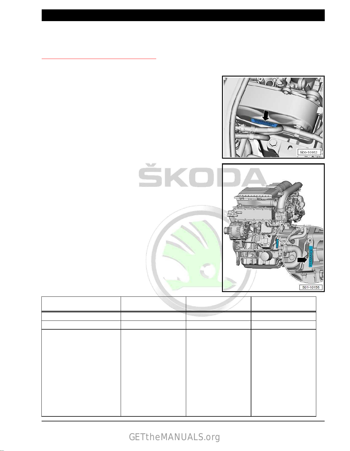
1.1 Engine number, engine data
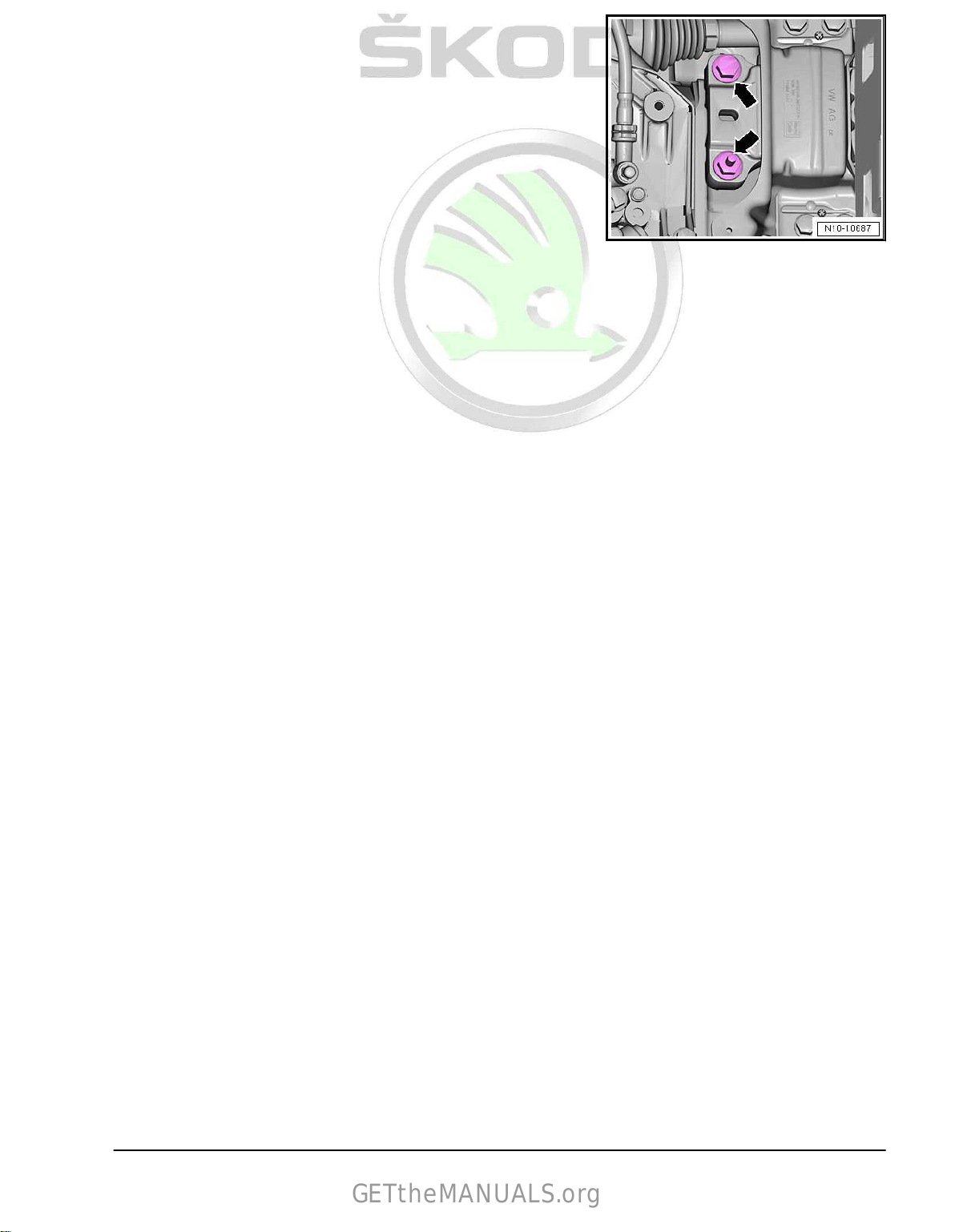
“The engine identification characters” and the “serial number” are
located on the sticker -arrow-
The “engine identification characters” and “serial number” are lo‐
cated on the cylinder block -arrow-.
The “engine identification characters” are also indicated on the
vehicle data sticker.
♦ Starting with the letter “C”, new four digit engine codes have
been introduced.
♦ The first 3 digits of the engine identification characters refer to
the displacement and the mechanical construction of the en‐
gine. They are type-punched on the cylinder block including
the serial number.
♦ The 4th digit refers to the output and torque of the engine and
depends upon the engine - J623- control unit.
Fitting locations for vehicle data stickers:
♦ ⇒ Maintenance ; Booklet Superb III
♦ ⇒ Maintenance ; Booklet Kodiaq
at the top timing belt guard.
Engine identification charac‐
ters
Superb III production 06.2015 ► 10.2015 ► 03.2015 ►
Kodiaq production 01.2017 ► 10.2016 ► 01.2017 ►
Emission standards EU6 EU6 EU6
Displacement
Power output kW at
Torque Nm at
Bore ∅ mm 74,5 74,5 74,5
Stroke mm 80,0 80,0 80,0
Compression ratio 10,5 10,5 10,5
Cylinder / valves per cylinder 4/4 4/4 4/4
Fuel - RON min. 95 unleaded 95 unleaded 95 unleaded
cm
rpm
rpm
3
CZCA CZDA CZEA
1395 1395 1395
92/5000-6000 110/5000-6000 110/5000-6000
200/1400-4000 250/1500-3500 250/1500-3500
1. Identification 1
Page 8

Protected by copyright. Copying for private or commercial purposes, in part or in whole, is not permitted
unless authorised by ŠKODA AUTO A. S. ŠKODA AUTO A. S. does not guarantee or accept any liability
with respect to the correctness of information in this document. Copyright by ŠKODA AUTO A. S.�
Engine identification charac‐
GETtheMANUALS.org
ters
Ignition system/fuel injection Motronic ME 17 Motronic ME 17 Motronic ME 17
Firing order 1-3-4-2 1-3-4-2 1-3-4-2
Exhaust gas recirculation no no no
Balancing shaft module no no no
Intake manifold change-over no no no
Camshaft control valve, inlet /
exhaust
Exhaust gas turbocharger yes yes yes
CZCA CZDA CZEA
yes / no yes / yes yes / yes
2 Rep. gr.00 - Technical data
Page 9

Protected by copyright. Copying for private or commercial purposes, in part or in whole, is not permitted
unless authorised by ŠKODA AUTO A. S. ŠKODA AUTO A. S. does not guarantee or accept any liability
with respect to the correctness of information in this document. Copyright by ŠKODA AUTO A. S.�
2 Safety instructions
GETtheMANUALS.org
⇒ “2.1 Safety precautions when working on fuel supply system”,
page 3
⇒ “2.2 Safety precautions when working on vehicles with a start/
stop system”, page 3
⇒ “2.3 Safety precautions during road tests in which testing and
measuring equipment is used”, page 4
⇒ “2.4 Safety precautions when working on cooling system”, page
4
⇒ “2.5 Safety precautions when working on ignition system”, page
4
⇒ “2.6 General safety instructions”, page 4
2.1 Safety precautions when working on
fuel supply system
Fuel under very high pressure creates a risk of injury.
– Wear protective gloves.
– Wear safety goggles.
– Decrease fuel pressure to residual pressure
⇒ “1.2 Reduce fuel pressure”, page 292 .
Place a clean cloth around the connection point and loosen the
connection point carefully before opening the fuel system.
Leaking fuel creates a fire hazard.
Fuel pump is activated by switching on ignition and via driver door
contact switch. Therefore, if the battery power hasn't been dis‐
connected, for safety reasons the plug of the fuel delivery unit
must be disconnected, or the fuel pump fuse must be removed
before opening the fuel system.
– Take out fuse for fuel pump control unit - J538- ⇒ Current flow
diagrams, Electrical fault finding and Fitting locations.
Risk
of damage to the electronic components when disconnecting
the battery.
Only disconnect the battery when the ignition is switched off ⇒
Electrical system; Rep. gr. 27 ; Battery; Disconnecting and con‐
necting battery .
2.2 Safety precautions
hicles with a start/stop system
Risk of injury as a result of automatic engine start in vehicles with
start/stop system.
In vehicles with an activated start-stop system (indicated by a
message in
ically if necessary.
– Ensure that the start-stop system is deactivated when carrying
out work on the vehicle (switch ignition off, if required switch
ignition on again).
the dash panel insert), the engine can start automat‐
when working on ve‐
2. Safety instructions 3
Page 10

Protected by copyright. Copying for private or commercial purposes, in part or in whole, is not permitted
unless authorised by ŠKODA AUTO A. S. ŠKODA AUTO A. S. does not guarantee or accept any liability
with respect to the correctness of information in this document. Copyright by ŠKODA AUTO A. S.�
2.3 Safety precautions during road tests in
GETtheMANUALS.org
which testing and measuring equipment
is used
Risk of accident due to deflection
Using testers and measuring instruments during driving operation
creates a risk of deflection.
There is a risk of injury due to insufficient securing of testers and
measuring instruments.
Increased risk of injury from unsecured testers and measuring
instruments must be prevented.
Measuring instruments can turn into dangerous projectiles on air‐
bag activation.
Testers and measuring instruments must always be secured on
the rear
there.
seat using a seat belt and operated by a 2nd person from
2.4 Safety precautions when working on cooling system
Risk of injury due to hot steams.
– Wear protective gloves.
– Wear safety goggles.
Relieve any possible pressure prior to the repair.
When the engine is warm, the cooling system is under overpres‐
sure.
Hot steam may escape when the compensation bottle is opened.
– Cover the cap of the coolant expansion tank with a cloth and
open carefully.
2.5 Safety precautions when working on ig‐
nition system
Risk of injury due to high voltage.
– Do not touch the ignition system with the engine running or at
start speed.
Risk of damage to injection and ignition system
– Ignition must be switched off before disconnecting and re-
connecting the cables of the fuel injection and the ignition
system as well as of the test equipment.
Switch off ignition before an engine wash.
2.6 General safety instructions
The safety measures for the pressure reduction in the high pres‐
sure system must be observed
⇒ “1.2 Reduce fuel pressure”, page 292 .
Place a clean cleaning cloth around the connection point before
detaching hose connections. Reduce pressure by carefully re‐
moving the hose.
– Do not touch or remove ignition leads with the engine running
or at start speed.
Ignition must be switched off before disconnecting and re-con‐
necting the
well as of the test equipment.
cables of the fuel injection and the ignition system as
4 Rep. gr.00 - Technical data
Page 11

Protected by copyright. Copying for private or commercial purposes, in part or in whole, is not permitted
unless authorised by ŠKODA AUTO A. S. ŠKODA AUTO A. S. does not guarantee or accept any liability
with respect to the correctness of information in this document. Copyright by ŠKODA AUTO A. S.�
If the engine must be operated at start speed without it starting,
GETtheMANUALS.org
as for example, when checking the compression pressure, re‐
move the fuse for the voltage supply of the injection valves and
the ignition coils from the fuse holder ⇒ Current flow diagrams,
Electrical fault finding and Fitting locations.
2. Safety instructions 5
Page 12

Protected by copyright. Copying for private or commercial purposes, in part or in whole, is not permitted
unless authorised by ŠKODA AUTO A. S. ŠKODA AUTO A. S. does not guarantee or accept any liability
with respect to the correctness of information in this document. Copyright by ŠKODA AUTO A. S.�
3 Repair instructions
GETtheMANUALS.org
⇒ “3.1 Cleanliness rules”, page 6
⇒ “3.2 Foreign bodies in the engine”, page 6
⇒ “3.3 Contact corrosion”, page 6
⇒ “3.4 Cable routing and securing”, page 6
⇒ “3.5 Assembly of radiators and condensers”, page 7
⇒ “3.6 General repair instructions”, page 7
3.1 Cleanliness rules
Carefully observe the following “rules” for cleanliness when work‐
ing on the fuel supply/injection system:
♦ Thoroughly clean the connection points and their surroundings
before releasing.
♦ Place removed parts on a clean surface and cover. Use lint-
free cloths.
♦ Carefully cover or close opened components if the repair is not
completed immediately.
♦ Only install clean parts: Only unpack replacement parts im‐
mediately prior
stored unwrapped (e.g. in tool boxes etc.).
♦ When the system is open: Do not work with compressed air.
Do not move vehicle.
♦ Ensure that no fuel runs onto the fuel hoses. If happens, clean
the hoses immediately.
♦ Protect electrical plug connections from dirt and moisture and
only connect them when dry.
3.2 Foreign bodies in the engine
To prevent penetration of foreign bodies, open channels of the
inlet connection and exhaust tract must be sealed with suitable
plugs during assembly works on the engine, e.g. from the screw
plug set for engine , e.g. -VAS 6122- .
to fitting. Do not use any parts which have been
3.3 Contact corrosion
The use of unsuitable connection elements causes contact cor‐
rosion (screws, nuts, washers, …).
This is why only connection elements with a special surface coat‐
ings are fitted.
Therefore, the rubber or plastic parts and the adhesives are made
from electrically non-conductive materials.
If there is a question mark about the suitability of parts, generally
use new parts ⇒ Electronic Catalogue of Original Parts “ETKA” .
3.4 Cable routing and securing
Lay lines of all kinds in such a way that the original line guide is
re-established.
♦ Fuel feed lines
♦ Hydraulic lines
♦ Brake fluid lines
♦ Coolant lines
6 Rep. gr.00 - Technical data
Page 13
Protected by copyright. Copying for private or commercial purposes, in part or in whole, is not permitted
unless authorised by ŠKODA AUTO A. S. ŠKODA AUTO A. S. does not guarantee or accept any liability
with respect to the correctness of information in this document. Copyright by ŠKODA AUTO A. S.�
♦ Vacuum lines
GETtheMANUALS.org
♦ Activated charcoal filter system lines
♦ Electrical lines
To rule out mix ups and ensure the original fitting position, mark
the lines before disassembly.
Make photos or sketches where necessary.
To avoid damage to lines, ensure sufficient clearance from all
moving or hot components.
Insulation or heat shield matts must be installed again in their
original position.
Secure all hose connections with hose clamps, assignment⇒
Electronic Catalogue of Original Parts .
When installing fit the coolant hoses free of stress, without them
touching any other components (pay attention to the marking on
the coolant connection and hose).
3.5 Assembly of radiators and condensers
The radiator, condenser and charge air cooler may have minor
indentations on
case of damage. Radiator, condensers or charge air cooler must
not be replaced because of these indentations.
the fins, even if assembly is correct. This is not a
3.6 General repair instructions
⇒ “3.6.1 Additional instructions when undertaking assembly work
on the air-conditioning system”, page 7
⇒ “3.6.2 General instructions for charge air system”, page 8
⇒ “3.6.3 General notes on the ignition system”, page 8
⇒ “3.6.4 General notes on the injection system”, page 9
3.6.1 Additional instructions when undertak‐
ing assembly work on the air-condition‐
ing system
CAUTION
Risk of frost due to refrigerant.
Do not open the refrigerant circuit of the air conditioning system.
In order to avoid damage to the condenser as well as to the re‐
frigerant lines
over-tensioned, kinked or bent.
Steps which should be taken in order to remove and install the
engine without opening the refrigerant circuit
– Remove the holding clamp(s) of the coolant lines.
– Removing AC compressor ⇒ Heating, Air Conditioning; Rep.
gr. 87 ; AC compressor; installing and removing AC compres‐
sor .
– Mount the AC compressor in such a way that the refrigerant
lines/hoses are not under tension.
and hoses, ensure that the lines and hoses are not
3. Repair instructions 7
Page 14

Protected by copyright. Copying for private or commercial purposes, in part or in whole, is not permitted
unless authorised by ŠKODA AUTO A. S. ŠKODA AUTO A. S. does not guarantee or accept any liability
with respect to the correctness of information in this document. Copyright by ŠKODA AUTO A. S.�
3.6.2 General instructions for charge air sys‐
GETtheMANUALS.org
tem
When undertaking all installation work, particularly in the engine
compartment because of its cramped construction, please ob‐
serve the following:
♦ Lay lines of all kinds (for example, for fuel, hydraulic fluid,
cooling fluid and refrigerant, brake fluid, vacuum) and electri‐
cal lines in such a way that the original line guide is reestablished.
♦ Ensure that there is adequate free access to all moving or hot
components.
In case a mechanical damage to the exhaust gas turbocharger is
found, for example, damage to the compressor wheel, it is not
sufficient to only replace the turbocharger. In order to avoid con‐
sequential damage, perform the following tasks:
♦ Clean all oil lines.
♦ Change engine oil and oil filter.
♦ Inspect the air filter housing, the air filter element and the in‐
take hoses for contaminations.
♦ Inspect the whole charge-air routing and the charge air cooler
for foreign bodies.
♦ The charge-air system must be tight.
♦ Replace self-locking nuts.
♦ Hose connections and hoses for the charge air system must
be free of oil and grease before being installed.
♦ Only install approved clamps for securing the hose connec‐
tions ⇒ ETKA - Electronic Catalogue of Original Parts .
♦ Spring-type clip pliers are recommended for installation of
spring-type clips.
♦ Before connecting the oil feed line, fill the exhaust turbocharg‐
er via the connection fitting with engine oil.
♦ To ensure the oil supply to the exhaust gas turbocharger,
leave the
exhaust gas turbocharger.
engine running for about 1 minute after installing the
3.6.3 General notes on the ignition system
♦ Switch off the ignition before disconnecting and connecting the
battery, as this may damage the engine control unit.
♦ The engine control unit and further components are equipped
with self-diagnosis; inspect ⇒ Vehicle diagnostic tester.
♦ A minimum voltage of 11.5 V is required for perfect functioning
of the electrical components.
♦ Certain inspections may cause the control unit to detect and
store a fault. It is therefore necessary to interrogate the event
memory after having completed all inspections and repairs,
and if necessary delete ⇒ Vehicle diagnostic tester.
Safety measures
⇒ “2.5 Safety precautions when working on ignition system”, page
4 .
Setting data, spark plugs:
♦ ⇒ Maintenance ; Booklet Superb III
♦ ⇒ Maintenance ; Booklet Kodiaq
8 Rep. gr.00 - Technical data
Page 15

Protected by copyright. Copying for private or commercial purposes, in part or in whole, is not permitted
unless authorised by ŠKODA AUTO A. S. ŠKODA AUTO A. S. does not guarantee or accept any liability
with respect to the correctness of information in this document. Copyright by ŠKODA AUTO A. S.�
3.6.4 General notes on the injection system
GETtheMANUALS.org
♦ The engine control unit is equipped with a self-diagnosis sys‐
tem. Before repairs and also for fault finding, first of all inter‐
rogate the event memory. Also check the vacuum hoses and
connections (unmetered air).
♦ Fuel hoses in the engine compartment must only be secured
with spring clips ⇒ ETKA - Electronic catalogue of original
parts . The use of clamp-type or screw-type clips is not al‐
lowed.
♦ A minimum voltage of 11.5 V is required for perfect functioning
of the electrical components.
♦ Do not use sealants containing silicone. Traces of silicone el‐
ements drawn
damage the lambda probe.
♦ Certain inspections may cause the control unit to detect and
store a fault. It is therefore necessary to interrogate the event
memory after having completed all inspections and repairs,
and if necessary delete ⇒ Vehicle diagnostic tester.
Safety precautions when working on the injection system
⇒ “2.6 General safety instructions”, page 4 .
in by the engine are not burnt in the engine and
3. Repair instructions 9
Page 16

Protected by copyright. Copying for private or commercial purposes, in part or in whole, is not permitted
unless authorised by ŠKODA AUTO A. S. ŠKODA AUTO A. S. does not guarantee or accept any liability
with respect to the correctness of information in this document. Copyright by ŠKODA AUTO A. S.�
10 – Removing and installing engine
GETtheMANUALS.org
1 Removing and installing engine
⇒ “1.1 Removing engine”, page 10
⇒ “1.2 Separate engine and gearbox”, page 19
⇒ “1.3 Attach engine attached to engine and gearbox mount”,
page 20
⇒ “1.4 Installing engine”, page 21
1.1 Removing engine
Special tools and workshop equipment required
♦ Removal tool for inner lining of the door panel - MP8-602/1♦ Extension - 2024 A /1- of lifting device - MP9-201 (2024A)♦ Engine and gearbox jack , e.g. -V.A.G 1383A- or -VAS 6931♦ Engine mount - T10497A♦ Hose strap pliers , e.g. -VAS 6362♦ Locking pin - T10060A♦ Double ladder , e. g. -VAS 5085♦ Protective goggles and gloves
♦ Radiator protection mat - VAS 531003-
Note
♦
The engine is removed downwards together with the gearbox.
♦
All cable straps that have been loosened or cut open when the
engine was removed must be attached again in the same lo‐
cation when the engine is installed again.
♦
Leave the ignition key in the ignition lock so that the steering
lock does not click into place.
– Remove the front wheels ⇒ Chassis, axles, steering; Rep. gr.
44 ; Wheels, tyres .
– Remove the sound dampening system ⇒ General body re‐
pairs, exterior ; Rep. gr. 66 ; Noise insulation; Summary of
components - noise insulation .
– Remove the front left and right wheelhouse liner ⇒ General
body repairs, exterior; Rep. gr. 66 ; Wheelhouse liner; remov‐
ing and installing front wheelhouse liner .
– Remove air filter housing
⇒ “3.2 Removing and installing air filter housing”, page 302 .
WARNING
Fuel under very high pressure creates a risk of injury.
– Reduce the fuel pressure in the high pressure system
⇒ “1.2 Reduce fuel pressure”, page 292 .
10 Rep. gr.10 - Removing and installing engine
Page 17
Protected by copyright. Copying for private or commercial purposes, in part or in whole, is not permitted
unless authorised by ŠKODA AUTO A. S. ŠKODA AUTO A. S. does not guarantee or accept any liability
with respect to the correctness of information in this document. Copyright by ŠKODA AUTO A. S.�
– Drain coolant
GETtheMANUALS.org
⇒ “1.3 Draining and filling up coolant”, page 225 .
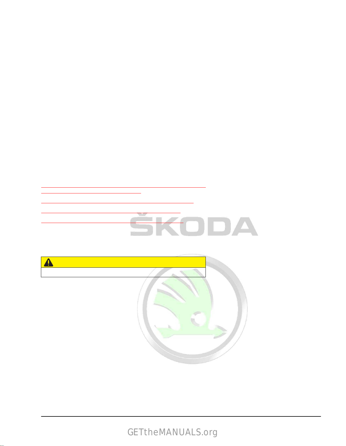
– Release screw left and right arrow -2-.
– Unclip and remove the air guide on the lock carrier.
– Remove battery
and battery tray ⇒ Electrical system; Rep. gr.
27 ; Battery; Removing and installing battery .
– Removing fan shroud
⇒ “4.4 Removing and installing radiator cowling with radiator
fan”, page 257 .
– Cover radiator with radiator protection mat - VAS 531003- .
Vehicles with air conditioning
– Remove the ribbed V-belt
⇒ “1.3.2 Removing and installing V-ribbed belt - Vehicles with
air conditioning”, page 42 .
CAUTION
Risk of frost due to refrigerant.
Do not open the refrigerant circuit of the air conditioning system.
– Disconnect plug connection -1- on the control valve for the air
conditioning system compressor - N280- .
– Release screws -arrows- for AC compressor.
NOTICE
Risk of damaging AC compressor, refrigerant lines and hoses.
♦ Do not over-tension, buckle or bend refrigerant lines and ho‐
ses.
– Remove AC
compressor with connected refrigerant hoses and
strap up to the right side.
Continued for all vehicles
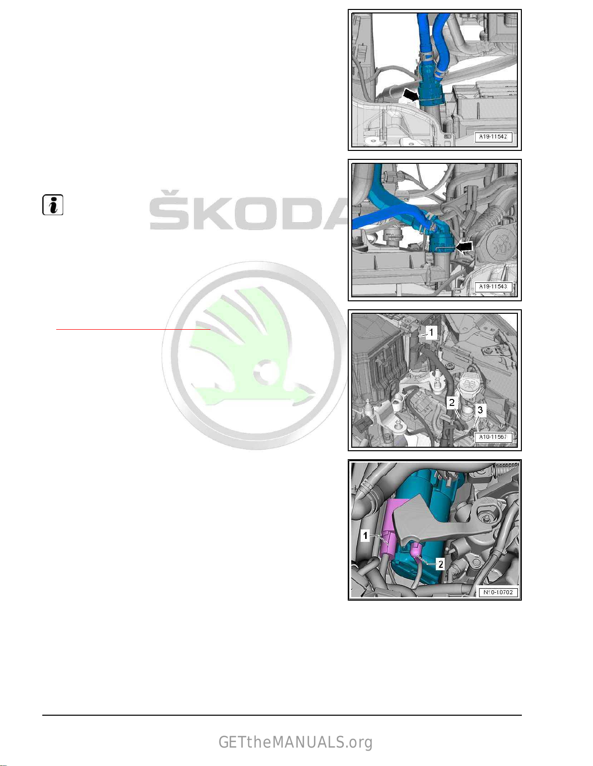
– Unlock catch -arrow- and remove vacuum hose -1-.
– Expose vacuum hose on the air guide pipe -2-.
1. Removing and installing engine 11
Page 18
Protected by copyright. Copying for private or commercial purposes, in part or in whole, is not permitted
unless authorised by ŠKODA AUTO A. S. ŠKODA AUTO A. S. does not guarantee or accept any liability
with respect to the correctness of information in this document. Copyright by ŠKODA AUTO A. S.�
Vehicles without auxiliary heating
GETtheMANUALS.org
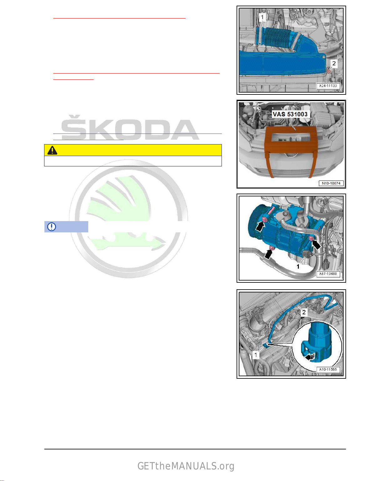
– Raise holding clamps -arrows- and remove coolant hoses
from heat exchanger for heating.
Vehicles with auxiliary heating
– Loosen holding clamp and holding clamps and pull off both
coolant hoses -arrows-.
Continued for all vehicles
– Mark the position of the clamp.
Note
♦
Before loosening the separation point between catalytic con‐
verter and turbocharger, mark the position of the clamp.
♦
Put the clamp back into position when assembling!
– Unscrew screw -2- and remove screw clamp.
– Remove screw -1-, remove nuts -arrows- and strap up cata‐
lytic converter to the bodyshell so as not to damage the
decoupling element.
Note
do not twist decoupling element in the exhaust pipe more than
10° - risk of damage
12 Rep. gr.10 - Removing and installing engine
Page 19

Protected by copyright. Copying for private or commercial purposes, in part or in whole, is not permitted
unless authorised by ŠKODA AUTO A. S. ŠKODA AUTO A. S. does not guarantee or accept any liability
with respect to the correctness of information in this document. Copyright by ŠKODA AUTO A. S.�
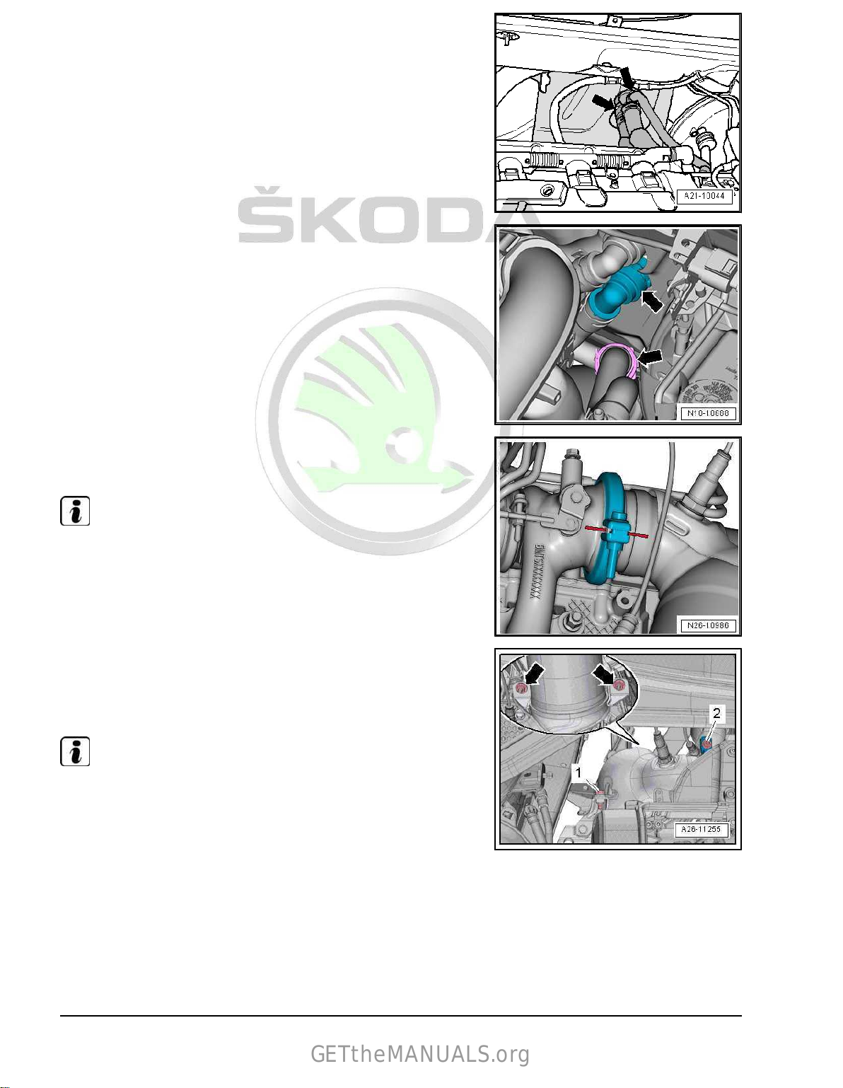
– Release screws -arrows- and remove holder.
GETtheMANUALS.org
Note
Place a cloth below to absorb leaking coolant.
– Loosen hose clamp -1- and remove coolant hose.
CAUTION
Risk of injury from fuel under pressure.
♦ To relieve the fuel pressure, place a clean cloth around the
connection point
and loosen the connection point carefully be‐
fore opening the fuel system.
NOTICE
Risk of malfunctions caused by soiling.
Observe safety measures and rules for cleanliness
⇒ “3.1 Cleanliness rules”, page 6 .
– Separate fuel feed line -1- and the line to activated charcoal
filter -2-.
– Loosen hose clamp -2- and remove coolant hose.
1. Removing and installing engine 13
Page 20
Protected by copyright. Copying for private or commercial purposes, in part or in whole, is not permitted
unless authorised by ŠKODA AUTO A. S. ŠKODA AUTO A. S. does not guarantee or accept any liability
with respect to the correctness of information in this document. Copyright by ŠKODA AUTO A. S.�
– Raise holding clamp -arrow- and disconnect coolant hose right
GETtheMANUALS.org
above radiator for charge air circuit.
– Raise holding clamp -arrow- and remove top left coolant hose
from radiator.
Note
For the following clip unclipping procedure use the removal tool
for inner door trim panel - MP8-602/1- .
– Unplug connector -1- on the engine control unit - J623-
⇒ “6 Engine control unit”, page 315 .
– Take electrical plug connections -2- and -3- out of the holder
and disconnect.
– Expose electric cables.
– Separate electrical plug connection -2-.
– Press back B+-pole protection -1- and unscrew B+-cable from
the starter magnet switch.
–
Unscrew the earth cable on the body.
14 Rep. gr.10 - Removing and installing engine
Page 21
Protected by copyright. Copying for private or commercial purposes, in part or in whole, is not permitted
unless authorised by ŠKODA AUTO A. S. ŠKODA AUTO A. S. does not guarantee or accept any liability
with respect to the correctness of information in this document. Copyright by ŠKODA AUTO A. S.�
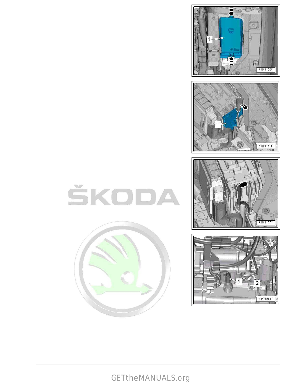
– Unlock catches -arrows-, remove cover -1- for E-box in the
GETtheMANUALS.org
engine compartment.
– Unlock catch with a screwdriver -arrow- and pull cover -1- for
E-box in the engine compartment upwards.
– Unscrew nut -arrow-, remove and expose electric cable.
Vehicles fitted with a manual gearbox
– Disconnect plug connections -1- and -2-.
– Remove gearshift mechanism from the gearbox ⇒ Rep. gr.
34 ;
Gearshift mechanism; removing and installing shift mech‐
anism .
– Disconnect breather from slave cylinder ⇒ Rep. gr. 30 ; Clutch
mechanism; Removing and installing the breather .
Vehicles with automatic gearbox
– Remove selector lever linkage from gearbox, disconnect me‐
chatronics connector and remove all holders from the gearbox
⇒ Rep. gr. 37 ; Shift mechanism; installing and removing shift
mechanism .
– Disconnect plugs from mechatronics ⇒ Rep. gr. 34 ; Remov‐
ing and installing the gearbox; remove gearbox .
– Expose electric cable.
1. Removing and installing engine 15
Page 22
Protected by copyright. Copying for private or commercial purposes, in part or in whole, is not permitted
unless authorised by ŠKODA AUTO A. S. ŠKODA AUTO A. S. does not guarantee or accept any liability
with respect to the correctness of information in this document. Copyright by ŠKODA AUTO A. S.�
Continued for all vehicles
GETtheMANUALS.org
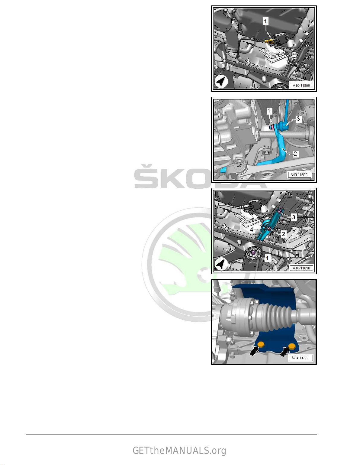
– Disconnect plug
- G266- .
– Unscrew nuts on left and right -1- for coupling rods -3- on anti-
roll bar -2-.
-1- at the oil level and oil temperature sender
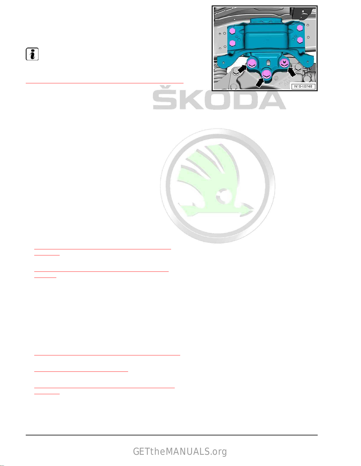
– Undo screws -1-, -2-, -3- and remove the pendulum support
-4-.
– Release screws
dan shaft.
For vehicles with four-wheel drive
– Remove angle gearbox ⇒ Gearbox; Rep. gr. 34 ; Angle gear‐
box; Remove angle gearbox .
For Superb III vehicles with automatic gearbox
– Remove assembly carrier ⇒ Running gear, axles, steering;
Rep. gr. 40 ; Assembly carrier; Removing and installing as‐
sembly carrier with steering gear .
-arrows- and remove heat shield for right car‐
16 Rep. gr.10 - Removing and installing engine
Page 23
Protected by copyright. Copying for private or commercial purposes, in part or in whole, is not permitted
unless authorised by ŠKODA AUTO A. S. ŠKODA AUTO A. S. does not guarantee or accept any liability
with respect to the correctness of information in this document. Copyright by ŠKODA AUTO A. S.�
For Superb III vehicles with manual gearbox and for Kodiaq ve‐
GETtheMANUALS.org
hicles
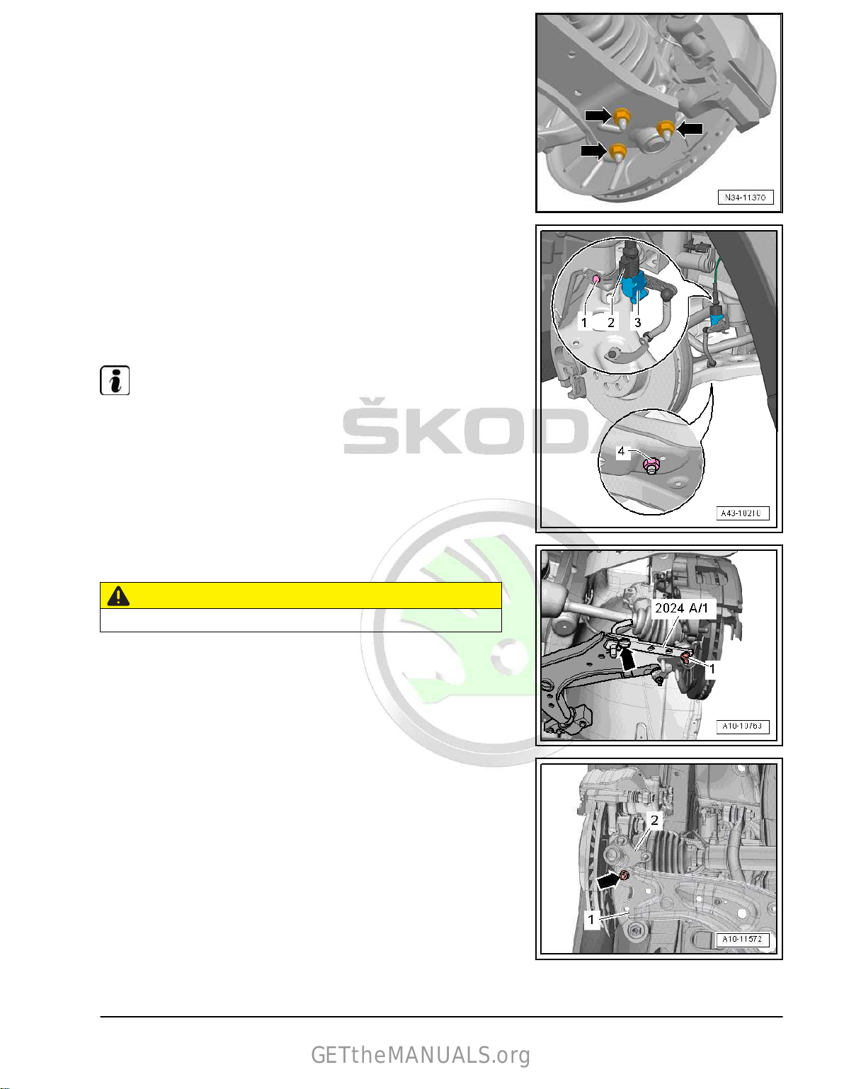
– Unscrew nuts -arrows- on left and right for swivel hub.
– If present, unscrew nuts -4- and screw -1- from the front left
vehicle level sensor - G78- -3- and place to one side.
– Unhook swivel hub from track control arm on left and right for
swivel hub.
– Unscrew left and right cardan shaft from gearbox ⇒ Chassis,
axles, steering; Rep. gr. 40 ; Cardan shaft; removing and in‐
stalling cardan shaft and tie up.
Note
Ensure that the surface protection of the cardan shaft is not dam‐
aged.
– Swivel suspension strut left towards the outside and support
with extension -2024 A /1- , as shown in the illustration.
CAUTION
There is a risk of accident from loose parts of the support.
– Secure rig pin with plug-in lock and swivel hub-arrow- and
nut-1-.
– Screw swivel hub -2- right at the track control arm -1- tight
using the nut -arrow-, as shown in the illustration.
1. Removing and installing engine 17
Page 24
Protected by copyright. Copying for private or commercial purposes, in part or in whole, is not permitted
unless authorised by ŠKODA AUTO A. S. ŠKODA AUTO A. S. does not guarantee or accept any liability
with respect to the correctness of information in this document. Copyright by ŠKODA AUTO A. S.�
Continued for all vehicles
GETtheMANUALS.org
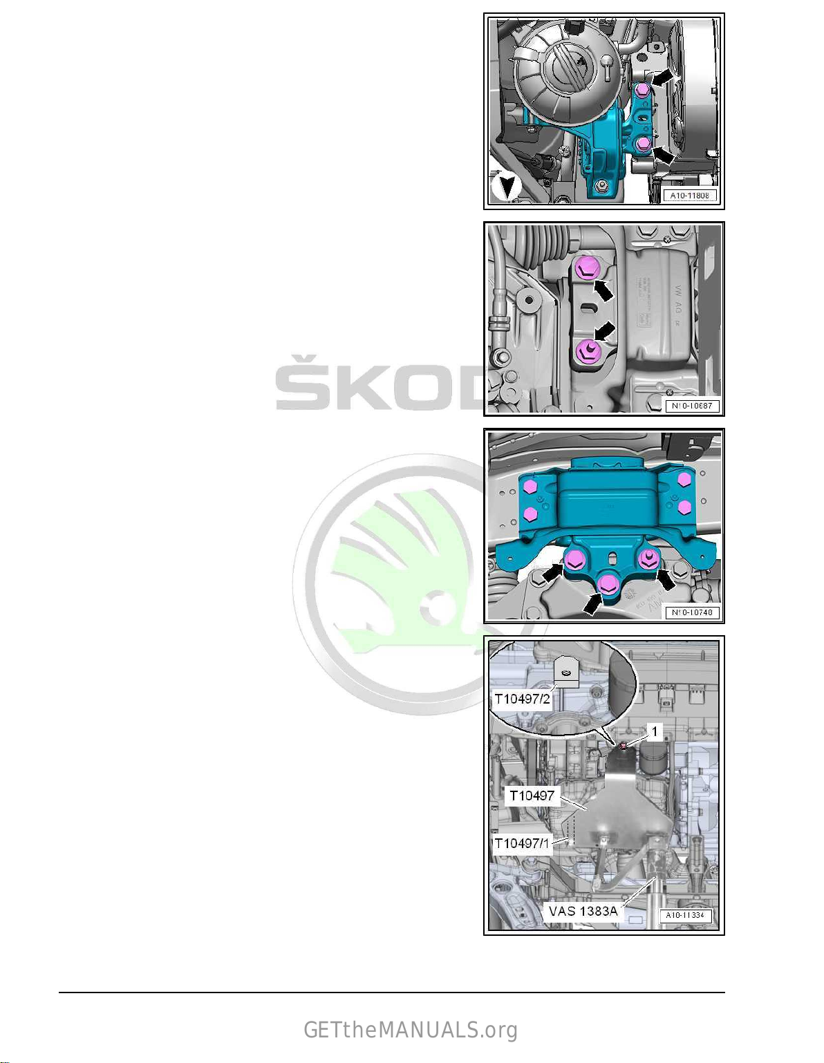
– Screw out screws -arrows- on engine mount by approximately
2 turns.
Gearbox mount with 2 screws
– Screw out screws -arrows- on gearbox mount by approxi‐
mately 2 turns.
Gearbox mount with 3 screws
– Screw out screws -arrows- on gearbox mount by approxi‐
mately 2 turns.
Continued for all vehicles
– Position clamping piece T10497A/2 on the housing fin of the
cylinder block, as shown in the illustration.
– Position
cylinder block.
– Screw clamping piece T10497A/2 with screw -1- onto the en‐
gine mount T10497A and tighten it to 20 Nm.
engine
mount - T10497A- with bolts T10497A/1 at the
18 Rep. gr.10 - Removing and installing engine
Page 25

Protected by copyright. Copying for private or commercial purposes, in part or in whole, is not permitted
unless authorised by ŠKODA AUTO A. S. ŠKODA AUTO A. S. does not guarantee or accept any liability
with respect to the correctness of information in this document. Copyright by ŠKODA AUTO A. S.�
– Fit the adapter - T10497A/3- to the engine mount - T10497A-
GETtheMANUALS.org
and tighten screw -1- to 20 Nm.
– Insert engine mount - T10497A- onto the engine and gearbox
jack
- V.A.G 1383A- or -VAS 6931- and lift the engine/gearbox
assembly a little.
Note
To remove the screws for the assembly mountings, use a com‐
mercially available double ladder , e. g. -VAS 5085- .
– Screw out engine mount screws -arrows- fully.
Gearbox mount with 2 screws
– Screw out gearbox mount screws -arrows- fully.
Gearbox mount with 3 screws
– Screw out gearbox mount screws -arrows- fully.
Continued for all vehicles
NOTICE
Risk of damaging vacuum lines or electric cables and the engine
compartment.
– Check that all vacuum lines and electric cables between en‐
gine, gearbox,
assembly mountings and body have been loos‐
ened.
– Drain engine/gearbox unit a little.
– Push the gearbox side of the engine/gearbox unit forwards
and drain it slowly and carefully.
1.2 Separate engine and gearbox
Special tools and workshop equipment required
♦ Additional hook - MP9-200/10 (10-222A/2)-
1. Removing and installing engine 19
Page 26
Protected by copyright. Copying for private or commercial purposes, in part or in whole, is not permitted
unless authorised by ŠKODA AUTO A. S. ŠKODA AUTO A. S. does not guarantee or accept any liability
with respect to the correctness of information in this document. Copyright by ŠKODA AUTO A. S.�
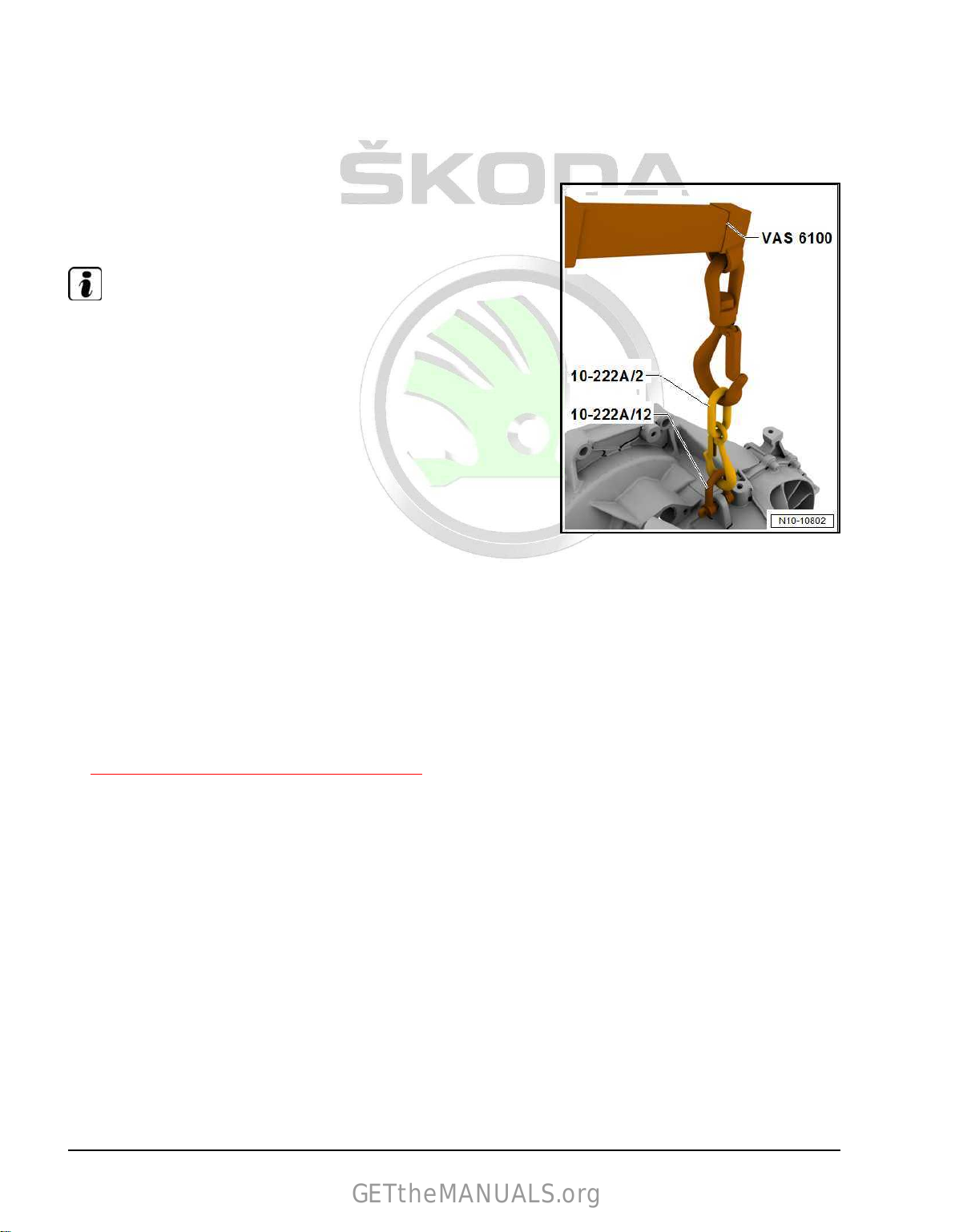
♦ Workshop crane , e.g. -VAS 6100-
GETtheMANUALS.org
♦ Lifting eye - 10-222A/12Work procedure
• Engine/gearbox unit removed and attached to engine mount T10497A- .
– Remove starter ⇒ Electrical system; Rep. gr. 27 ; Starter;
Removing and installing starter .
– Install shackle - 10-222A/12- on gearbox.
– Hook additional hook - MP9-200/10 (10-222A/2)- with shackle
- 10-222A/12- onto the workshop crane - VAS 6100- .
Note
Pre-load the workshop crane - VAS 6100- slightly, but do not raise
the gearbox.
– Unscrew engine/gearbox connecting screws ⇒ Rep. gr. 34 ;
Removing and installing gearbox .
– Remove gearbox from engine.
1.3 Attach engine attached to engine and
Special tools and workshop equipment required
♦ Supporting device - MP9-201 (2024A)♦ Engine and gearbox support - VAS 6095♦ Workshop crane , e.g. -VAS 6100Work procedure
• Gearbox disconnected from engine
⇒ “1.2 Separate engine and gearbox”, page 19 .
gearbox mount
20 Rep. gr.10 - Removing and installing engine
Page 27
Protected by copyright. Copying for private or commercial purposes, in part or in whole, is not permitted
unless authorised by ŠKODA AUTO A. S. ŠKODA AUTO A. S. does not guarantee or accept any liability
with respect to the correctness of information in this document. Copyright by ŠKODA AUTO A. S.�
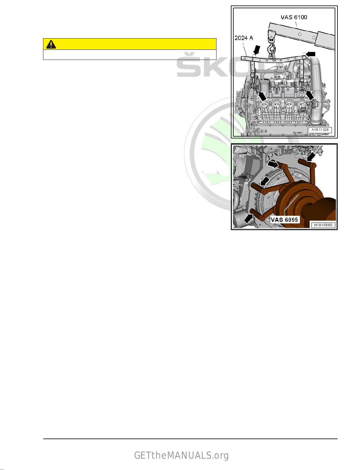
– Suspend lifting device - MP9-201 (2024A)- from the engine
GETtheMANUALS.org
and workshop
crane - VAS 6100- as shown in the illustration.
– For coordination with the unit centre of gravity position the
perforated rails must be placed as shown in the illustration.
CAUTION
There is a risk of accident from loose parts of the lifting device.
– The suspension hooks and rig pin on the lifting must be se‐
cured using plug-in locks -arrows-.
–
Lift engine with installed engine mount T10497A off the en‐
gine/gearbox jack - V.A.G 1383 A- with workshop crane VAS 6100- .
– Remove engine mount T10497A .
– Secure engine with bolts -arrows- at engine and gearbox
mount - VAS 6095- as shown in the illustration.
1.4 Installing engine
Special tools and workshop equipment required
♦ Extension - 2024 A /1- of lifting device - MP9-201 (2024A)♦ Engine and gearbox jack , e.g. -V.A.G 1383A- or -VAS 6931♦ Engine mount - T10497A♦ Hose strap pliers , e.g. -VAS 6362♦ Locking pin - T10060A♦ Double ladder , e. g. -VAS 5085♦ Protective goggles and gloves
♦ Grease - G 000 100For vehicles with manual gearbox
– Clean the serration of the drive shaft and if the clutch disc has
been used clean the hub serration, remove any corrosion
present
to the serration of the drive shaft.
– Subsequently move the clutch disc up and down on the drive
shaft until the hub fits smoothly on the shaft. Always remove
excess grease.
– Check centring of driven plate assembly ⇒ Rep. gr. 30 ;
Clutch; removing and installing clutch .
and only apply a very thin layer of grease - G 000 100-
1. Removing and installing engine 21
Page 28
Protected by copyright. Copying for private or commercial purposes, in part or in whole, is not permitted
unless authorised by ŠKODA AUTO A. S. ŠKODA AUTO A. S. does not guarantee or accept any liability
with respect to the correctness of information in this document. Copyright by ŠKODA AUTO A. S.�
– Check the clutch release bearing for wear. Replace release
GETtheMANUALS.org
bearing when
of components- Clutch release mechanism .
For vehicles with automatic gearbox
– Replace the needle bearing in the crankshaft
⇒ “3.2 Replace the needle bearing in the crankshaft”,
page 63 .
Continued for all vehicles
Installation is performed in the reverse order, pay attention to the
following points:
– Screws which have been tightened firmly to a torquing angle
must be replaced.
– Replace self-locking nuts, gasket rings, gaskets and O-rings.
• Secure all hose connection ends with spring-type clips that
comply with
of Original Parts .
• Fit all cable straps on again in the same place when installing.
– Installing intermediate plate
⇒ Fig. ““Installing intermediate plate”“ , page 53 .
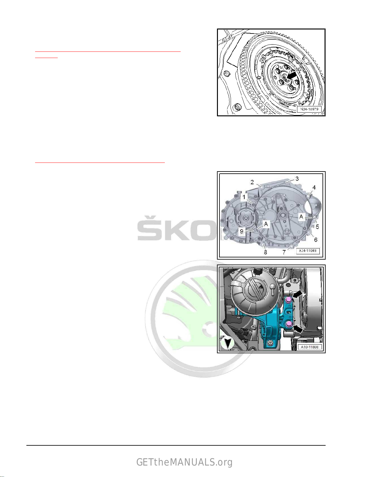
– If there are no dowel sleeves in the cylinder block for centering
the engine and gearbox, insert dowel sleeves
– Screw gearbox securely onto engine at positions -1-, -2-, -3-,
-6-, -7-, -8- and -9-.
– Install gearbox support bracket.
– Attach engine/gearbox unit to engine mount - T10497A- .
– Insert engine/gearbox unit into the body.
worn ⇒ Rep. gr. 30 ; Clutch control; Summary
the series design ⇒ ETKA - Electronic Catalogue
-A-.
– Initially insert screws -arrows- for engine mount by hand as far
as the stop.
22 Rep. gr.10 - Removing and installing engine
Page 29
Protected by copyright. Copying for private or commercial purposes, in part or in whole, is not permitted
unless authorised by ŠKODA AUTO A. S. ŠKODA AUTO A. S. does not guarantee or accept any liability
with respect to the correctness of information in this document. Copyright by ŠKODA AUTO A. S.�
Gearbox mount with 2 screws
GETtheMANUALS.org
– Initially insert screws -arrows- for gearbox mount by hand as
far as the stop.
1. Removing and installing engine 23
Page 30
Protected by copyright. Copying for private or commercial purposes, in part or in whole, is not permitted
unless authorised by ŠKODA AUTO A. S. ŠKODA AUTO A. S. does not guarantee or accept any liability
with respect to the correctness of information in this document. Copyright by ŠKODA AUTO A. S.�
Gearbox mount with 3 screws
GETtheMANUALS.org
– Initially insert screws -arrows- for gearbox mount by hand as
far as the stop.
Continued for all vehicles
Note
The screws must not be permanently tightened until the assembly
bracket is adjusted
⇒ “2.1 Assembly overview - assembly mountings”, page 26 .
– Remove engine mount - T10497A- from engine.
Vehicles fitted with a manual gearbox
– Connect breather to slave cylinder ⇒ Rep. gr. 30 ; Clutch
mechanism; Removing and installing the breather .
– Install linkages with cable support ⇒ Rep. gr. 34 ; Shift mech‐
anism; installing and removing shift mechanism .
Vehicles with automatic gearbox
– Install assembly carrier ⇒ Running gear, axles, steering; Rep.
gr. 40 ; Assembly carrier; Removing and installing assembly
carrier with steering box .
– Install selector lever linkage, install mechatronics connector
and install holders to the gearbox ⇒ Rep. gr. 37 ; Shift mech‐
anism; installing and removing shift mechanism .
For vehicles with four-wheel drive
– Install angle gearbox ⇒ Gearbox; Rep. gr. 34 ; Angle gearbox;
Remove angle gearbox .
Continued for all vehicles
– Install exhaust pipe with catalytic converter
⇒ “2.2 Removing and installing catalytic converter”,
page 354 .
– Install pendulum support
⇒ “2.1 Assembly overview - assembly mountings”,
page 26 .
– Install drive shafts ⇒ Running gear, axles, steering; Rep. gr.
40 ; Drive shaft; Removing and installing drive shaft .
– Install track control arm, steering joint and coupling rod ⇒
Chassis, Axles, steering; Rep. gr. 40 ; Bottom track control
arm, steering joint; Removing and installing the bottom track
control arm .
– Install AC compressor ⇒ Heating, Air Conditioning; Rep. gr.
– Install the V-ribbed belt
– Connect plug for engine control unit - J623-
– Connect coolant hoses with quick coupling
– Install the front left and right wheelhouse liner⇒ Exterior body
AC compressor; Removing and installing AC compressor .
87 ;
⇒ “1.3 Removing and installing V-ribbed belt”, page 41 .
⇒ “6 Engine control unit”, page 315 .
⇒ Fig. ““Connect coolant hose with quick coupling”“ ,
page 253 .
Rep. gr. 66 ; Wheelhouse liner; Removing and installing
work;
the front wheelhouse liner .
24 Rep. gr.10 - Removing and installing engine
Page 31

Protected by copyright. Copying for private or commercial purposes, in part or in whole, is not permitted
unless authorised by ŠKODA AUTO A. S. ŠKODA AUTO A. S. does not guarantee or accept any liability
with respect to the correctness of information in this document. Copyright by ŠKODA AUTO A. S.�
– Install the front wheels ⇒ Chassis, axles, steering; Rep. gr.
GETtheMANUALS.org
44 ; Wheels, tyres .
– Adjust the assembly bracket
⇒ “2.1 Assembly overview - assembly mountings”,
page 26 .
– Install battery tray and battery ⇒ Electrical system; Rep. gr.
27 ; Battery; Removing and installing battery .
– Install air filter housing
⇒ “3.2 Removing and installing air filter housing”, page 302 .
– Top up and bleed cooling system
⇒ “1.3 Draining and filling up coolant”, page 225 .
– Interrogate all event memories and delete all event entries
which are
caused by removing and installing the engine ⇒ Ve‐
hicle diagnostic tester.
– After deleting the event memory of the engine control unit the
readiness code must be re-generated.
NOTICE
Risk of damaging control units as a result of overvoltage.
♦ Do not use charger for jump starting!
Tightening torques
Note
♦
Tightening torques apply only for lightly greased, oiled,
phosphatized or blackened nuts and screws.
♦
Other lubricants such as engine and gearbox oil are allowed,
but no lubricants containing graphite.
♦
Do not use degreased parts.
Component
Specified torque
Screws/nuts M6 9 Nm
M7 15 Nm
M8 20 Nm
M10 40 Nm
M12 65 Nm
deviations:
Connecting screws on engine to gearbox ⇒ Rep. gr. 34 ; In‐
stalling and removing gearbox; tightening torques for gearbox
♦ Screws for assembly bracket
⇒ “2.1 Assembly overview - assembly mountings”,
page 26
♦ Cardan shaft guard ⇒ Chassis, axles, steering; Rep. gr. 40 ;
Cardan shaft; Removing and installing cardan shaft.
1. Removing and installing engine 25
Page 32
Protected by copyright. Copying for private or commercial purposes, in part or in whole, is not permitted
unless authorised by ŠKODA AUTO A. S. ŠKODA AUTO A. S. does not guarantee or accept any liability
with respect to the correctness of information in this document. Copyright by ŠKODA AUTO A. S.�
2 Assembly bracket
GETtheMANUALS.org
⇒ “2.1 Assembly overview - assembly mountings”, page 26
⇒ “2.2 Removing and installing engine mount”, page 28
⇒ “2.3 Removing and installing gearbox mount”, page 28
⇒ “2.4 Removing and installing pendulum support”, page 30
⇒ “2.5 Support the engine in its installed position”, page 31
⇒ “2.6 Adjusting the unit mounting”, page 33
⇒ “2.7 Check assembly bracket setting”, page 35
2.1 Assembly overview - assembly mountings
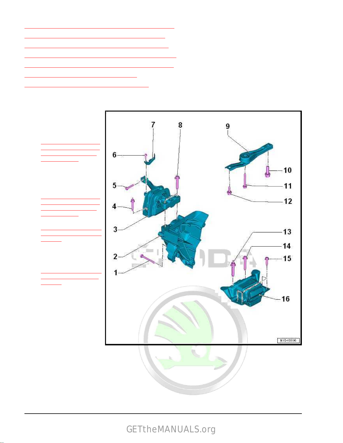
1 - Screw
❑ Replace after disas‐
sembly
❑
order of tightening
⇒ Fig. ““Engine support
bracket - tightening tor‐
que and tightening or‐
der”“ , page 27
❑ 45 Nm + 90°
2 - Engine support bracket
❑
Tightening torque and
tightening order
⇒ Fig. ““Engine support
bracket - tightening tor‐
que and tightening or‐
der”“ , page 27
❑ removing and installing
⇒ “1.6 Removing and in‐
stalling engine support”,
page 45
3 - Engine mounting
❑ with supporting arm
❑
removing and installing
⇒ “2.2 Removing and in‐
stalling engine mount”,
page 28
4 - Screw
❑ Replace after disas‐
sembly
❑
40 Nm + 90°
5 - Screw
❑ Replace after disas‐
sembly
❑ 20 Nm + 90°
6 - Screw
❑ 8 Nm
7 - Support
8 - Screw
❑ Replace after disassembly
❑ 60 Nm + 90°
26 Rep. gr.10 - Removing and installing engine
Page 33
Protected by copyright. Copying for private or commercial purposes, in part or in whole, is not permitted
unless authorised by ŠKODA AUTO A. S. ŠKODA AUTO A. S. does not guarantee or accept any liability
with respect to the correctness of information in this document. Copyright by ŠKODA AUTO A. S.�
9 - Pendulum support
GETtheMANUALS.org
❑ removing and installing ⇒ “2.4 Removing and installing pendulum support”, page 30
10 - Screw
❑ Replace after disassembly
❑
Tightening torque and tightening order
⇒ Fig. ““Pendulum support - tightening torque and tightening order”“ , page 27
11 - Screw
❑ Replace after disassembly
❑
Tightening torque and tightening order
⇒ Fig. ““Pendulum support - tightening torque and tightening order”“ , page 27
12 - Screw
❑ Replace after disassembly
❑
Tightening torque and tightening order
⇒ Fig. ““Pendulum support - tightening torque and tightening order”“ , page 27
13 - Screw
❑ Replace after disassembly
❑
Tightening torque ⇒ Rep. gr. 34 ; Assembly mountings; Summary of components - assembly mountings
14 - Screw
❑ Replace after disassembly
❑ Tightening torque ⇒ Rep. gr. 34 ; Assembly mountings; Summary of components - assembly mountings
15 - Screw
❑ Replace after disassembly
❑ 50 Nm + 90°
16 - Gearbox mount
❑ with supporting arm
❑ removing and installing
⇒ “2.3 Removing and installing gearbox mount”, page 28
Engine support bracket - tightening torque and tightening order
– Tighten screws gradually in the given sequence:
Stage Screws Tightening torque/torquing angle
1. -1…3- 7 Nm
2. -1…3- 40 Nm
3. -1…3- Turn 90° further
Pendulum support - tightening torque and tightening order
– Tighten screws gradually in the given sequence:
Stage Screws Tightening torque/torquing angle
1. -2-, -3- 50 Nm
2. -1- 130 Nm
3. -1…3- Turn 90° further
2. Assembly bracket 27
Page 34

Protected by copyright. Copying for private or commercial purposes, in part or in whole, is not permitted
unless authorised by ŠKODA AUTO A. S. ŠKODA AUTO A. S. does not guarantee or accept any liability
with respect to the correctness of information in this document. Copyright by ŠKODA AUTO A. S.�
2.2 Removing and installing engine mount
GETtheMANUALS.org
Removing
– Separate electrical plug connection -1-.
– Unclip holder -2- with hoses from the expansion tank and place
to one side.
–
Unlock catches using a screwdriver -arrow- and lay coolant
expansion tank to the side.
– Suspend engine into the installation position
⇒ “2.5 Support the engine in its installed position”,
page 31 .
– Release screws -arrows- and remove engine mount -1-.
Install
Installation is performed in the reverse order, pay attention to the
following points:
– Check assembly bracket setting
⇒ “2.7 Check assembly bracket setting”, page 35 .
Tightening torques
♦ Assembly bracket
⇒ “2.1 Assembly overview - assembly mountings”, page 26 .
2.3 Removing and
Removing
– Remove battery
Removing and installing battery .
– Remove engine control unit
⇒ “6 Engine control unit”, page 315 .
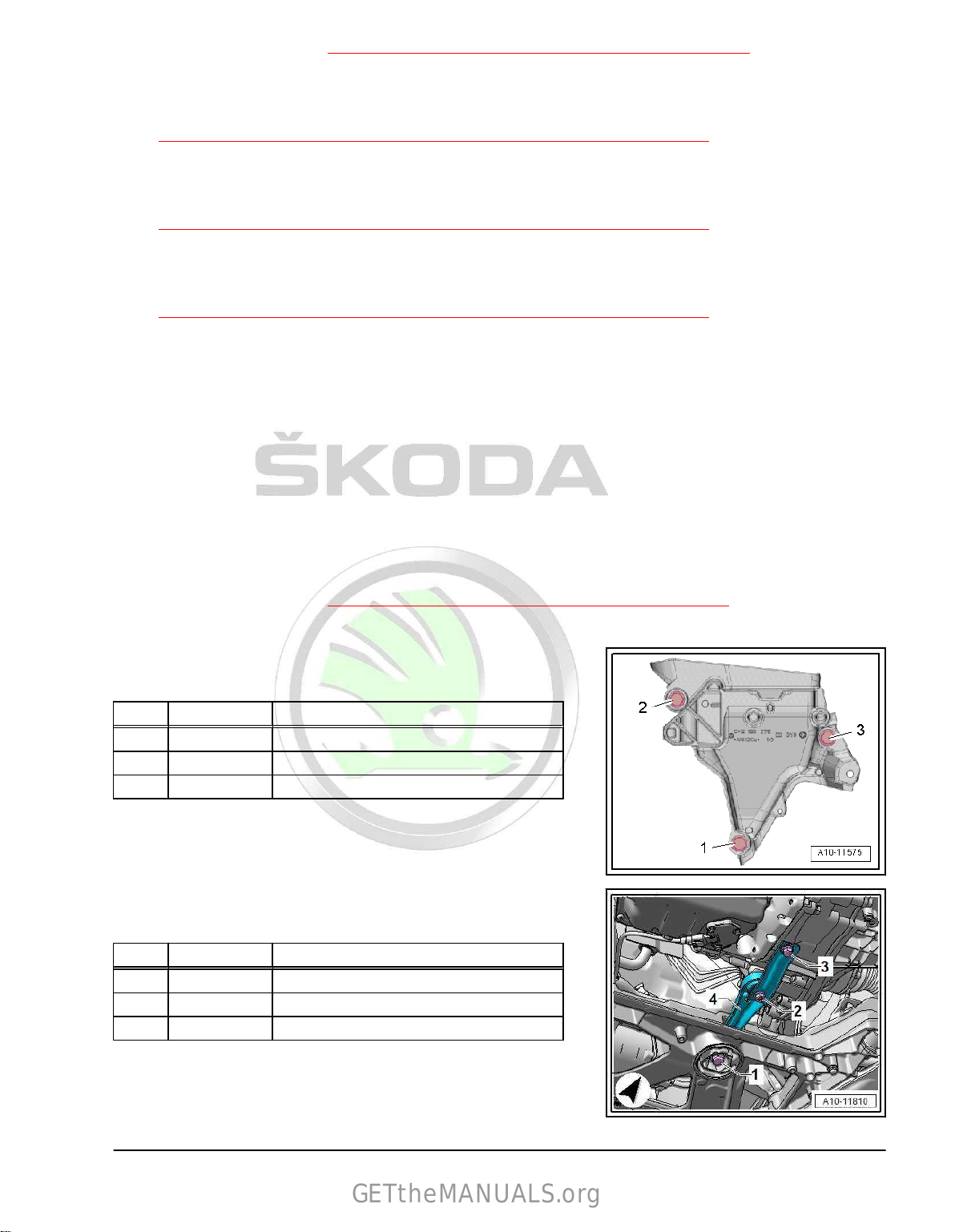
– Unscrew screws -arrows- and remove holder -1-.
Note
tray ⇒ Electrical system; Rep. gr. 27 ; Battery;
installing gearbox mount
Holders are installed differently according to build version.
28 Rep. gr.10 - Removing and installing engine
Page 35

Protected by copyright. Copying for private or commercial purposes, in part or in whole, is not permitted
unless authorised by ŠKODA AUTO A. S. ŠKODA AUTO A. S. does not guarantee or accept any liability
with respect to the correctness of information in this document. Copyright by ŠKODA AUTO A. S.�
– Unscrew screw
GETtheMANUALS.org
-1-, unclip upwards -arrows- and push slightly
to the side.
– Suspend engine into the installation position
⇒ “2.5 Support the engine in its installed position”,
page 31 .
Gearbox mount with 2 screws
– Release screws -arrows- and remove gearbox mount -1-.
2. Assembly bracket 29
Page 36

Protected by copyright. Copying for private or commercial purposes, in part or in whole, is not permitted
unless authorised by ŠKODA AUTO A. S. ŠKODA AUTO A. S. does not guarantee or accept any liability
with respect to the correctness of information in this document. Copyright by ŠKODA AUTO A. S.�
Gearbox mount with 3 screws
GETtheMANUALS.org
– Unscrew screws -2- and then screws -1-.
– Remove gearbox mount -1-.
Install
Installation is performed in the reverse order, pay attention to the
following points:
NOTICE
There is a risk of damaging the thread in the gearbox support
bracket by positioning the bolts obliquely.
♦ Before screwing in the screws -arrows- the gearbox support
bracket and supporting arm of the gearbox mount must be
absolutely parallel to each other. If necessary, push up gear‐
box at the rear using a hydraulic trolley jack.
♦ Do not remove supporting device - T30099- until the bolts se‐
curing the gearbox mount have been tightened to specified
torque.
– Lift gearbox with the support bracket spindle until the gearbox
support
mount.
– Check assembly bracket setting
⇒ “2.7 Check assembly bracket setting”, page 35 .
– Remove supporting device - T30099- .
Tightening torques
♦ Assembly bracket
⇒ “2.1 Assembly overview - assembly mountings”, page 26 .
bracket is touching the supporting arm of the gearbox
2.4 Removing and
installing pendulum sup‐
port
– Remove the sound dampening system ⇒ General body re‐
pairs, exterior ; Rep. gr. 66 ; Noise insulation; Summary of
components - noise insulation .
– Undo screws -1-, -2-, -3- and remove the pendulum support.
Install
Installation is performed in the reverse order, pay attention to the
following points:
Tightening torques
♦ Pendulum support
⇒ “2.1 Assembly overview - assembly mountings”, page 26
30 Rep. gr.10 - Removing and installing engine
Page 37

Protected by copyright. Copying for private or commercial purposes, in part or in whole, is not permitted
unless authorised by ŠKODA AUTO A. S. ŠKODA AUTO A. S. does not guarantee or accept any liability
with respect to the correctness of information in this document. Copyright by ŠKODA AUTO A. S.�
2.5 Support the engine in its installed posi‐
GETtheMANUALS.org
tion
⇒ “2.5.1 Support the engine in installation position, Superb III”,
page 31
⇒ “2.5.2 Support the engine in its installed position, Kodiaq”, page
32
2.5.1 Support the engine in installation posi‐
tion, Superb III
Special tools and workshop equipment required
♦ Surface - T30119♦ Support - 10-222A/31–3♦ Adapter - MP9-200/18 (10-222A/18)♦ Hook for MP9-200 and T30099 - MP9-200/10 (10-222A/10)♦ Supporting device - T30099♦ Adapter - T40091/3– Loosen hose clamps -1-, -2- and remove air guide pipes.
– Remove air filter housing
⇒ “3.2 Removing and installing air filter housing”, page 302 .
– Remove the plenum panel cover ⇒ External body repairs;
Rep. gr. 50 ; Bulkhead; Assembly overview - plenum panel
cover .
– Remove caps of screwed connections for front suspension
strut domes.
– Install adapter -3- with hook for MP9-200 and T30099 -4- and
support -2-.
– Place support bracket -5- with support -2- and base -1- on the
screwed connections of the front suspension strut domes.
1 -
Surface - T301192 - Support - 10-222A/31–33 - Adapter - MP9-200/18 (10-222A/18)4 - Hook for MP9-200 and T30099 - MP9-200/10 (10-222A/10)5 - Supporting device - T300996 - Adapter - T40091/3– Attach snap hook to the engine suspension eyes.
– Slightly pre-tension the engine/gearbox unit via hooks
MP9-200 and T30099 - MP9-200/10- , but do not raise.
Tightening torques
♦ Battery tray ⇒ Electrical system; Rep. gr. 27 ; Battery; Re‐
moving and installing battery
♦ Windscreen wiper arms ⇒ Electrical system; Rep. gr. 92 ;
Windscreen wiper system; Removing and installing wind‐
screen wiper arms .
2. Assembly bracket 31
Page 38
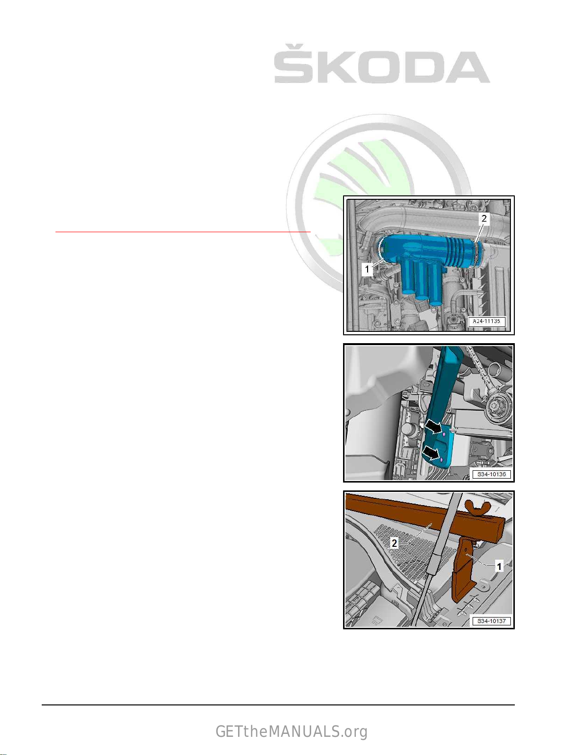
Protected by copyright. Copying for private or commercial purposes, in part or in whole, is not permitted
unless authorised by ŠKODA AUTO A. S. ŠKODA AUTO A. S. does not guarantee or accept any liability
with respect to the correctness of information in this document. Copyright by ŠKODA AUTO A. S.�
2.5.2 Support the engine in its installed posi‐
GETtheMANUALS.org
tion, Kodiaq
Special tools and workshop equipment required
♦ Supporting device - MP9–200 (10 - 222 A)♦ Adapter - 10 - 222 A /29♦ Adapter - MP9-200/18 (10-222A/18)♦ Hook for MP9-200 and T30099 - MP9-200/10 (10-222A/10)♦ Adapter - T40091/3♦ Carrier part - T40091/1♦ Spindle - T40093 /3♦ Adapter - T40093/3-6– Loosen hose clamps -1-, -2- and remove air guide pipes.
– Remove air filter housing
⇒ “3.2 Removing and installing air filter housing”, page 302 .
• To fit the supporting device , the cross member of the front wall
must be detached on the right side of the vehicle.
Detaching the cross member creates a space to fit the spindle T40093 /3-
– Remove the front right wheelhouse liner ⇒ General body re‐
pairs, exterior; Rep. gr. 66 ; Wheelhouse liner; Removing and
installing the front wheelhouse liner .
– Unscrew screws -arrows- and
the front wall.
with adapter - T40093/3-6- for the supporting device .
detach the cross member from
– Fit the adapter - 10 - 222 A /29- -1- under the wing plate on
both sides of the vehicle, as shown.
• Adapter with symbol “L” is installed on the “right” side of the
vehicle.
• Adapter with symbol “R” is installed on the “left” side of the
vehicle.
• The arrow shows the direction of travel on each side.
32 Rep. gr.10 - Removing and installing engine
Page 39

Protected by copyright. Copying for private or commercial purposes, in part or in whole, is not permitted
unless authorised by ŠKODA AUTO A. S. ŠKODA AUTO A. S. does not guarantee or accept any liability
with respect to the correctness of information in this document. Copyright by ŠKODA AUTO A. S.�
– Fit supporting device - MP9–200 (10 - 222 A)- together with
GETtheMANUALS.org
the other elements, as shown.
A - Adapter - MP9-200/18 (10-222A/18)B - Adapter - T40093/3-6C - Carrier part - T40091/1D - Spindle - T40093 /3E - Hook for MP9-200 and T30099 - MP9-200/10 (10-222A/10)F - Adapter - T40091/3G - Hook for MP9-200 and T30099 - MP9-200/10H - Supporting device - MP9–200 (10 - 222 A)I - Adapter - 10 - 222 A /29-
– Position the adapter - T40093/3-6- on the frame side rail as
shown.
• The adapter - T40093/3-6- must be secured by the bolt -A- to
the flange of the frame side rail -arrow-.
–
Connect adapter - T40093/3-6- to the spindle - T40093 /3- and
pre-tension assembled supporting device .
– Slightly pre-tension the engine/gearbox unit via hooks
MP9-200 and T30099 - MP9-200/10- , but do not raise.
2.6 Adjusting the unit mounting
– Suspend engine into the installation position
⇒ “2.5 Support the engine in its installed position”, page 31 .
– Unscrew screws -arrows- for engine mount one after another
and replace (if not already done during engine installation).
– Firstly, loosely insert the screws.
– Remove battery
tray ⇒ Electrical system; Rep. gr. 27 ; Battery;
Removing and installing battery .
2. Assembly bracket 33
Page 40

Protected by copyright. Copying for private or commercial purposes, in part or in whole, is not permitted
unless authorised by ŠKODA AUTO A. S. ŠKODA AUTO A. S. does not guarantee or accept any liability
with respect to the correctness of information in this document. Copyright by ŠKODA AUTO A. S.�
Gearbox mount with 2 screws
GETtheMANUALS.org
– Unscrew screws
and replace (if not already done during engine installation).
Gearbox mount with 3 screws
– Unscrew screws -arrows- for gearbox mount one after another
and replace (if not already done during engine installation).
Continued for all vehicles
– Firstly, loosely insert the screws.
-arrows- for gearbox mount one after another
– Move engine/gearbox unit with an assembly lever until the fol‐
lowing dimensions are set:
distance of -a- = 10 mm must be present between engine sup‐
A
port -2- and engine mount -1-.
The cast edge on the engine support -2- must be parallel with the
engine mount supporting arm -1-.
Dimension -b- = -b-.
Note
The distance -a- = 10 mm can be checked, for example with suit‐
able round bars.
– Tighten screws for engine mount.
Gearbox mount with 2 screws
– Make sure that on the gearbox side the edges of the support‐
ing arm -2- and gearbox support
• Dimension -x- = -x-.
-1- are parallel.
34 Rep. gr.10 - Removing and installing engine
Page 41

Protected by copyright. Copying for private or commercial purposes, in part or in whole, is not permitted
unless authorised by ŠKODA AUTO A. S. ŠKODA AUTO A. S. does not guarantee or accept any liability
with respect to the correctness of information in this document. Copyright by ŠKODA AUTO A. S.�
Gearbox mount with 3 screws
GETtheMANUALS.org
– Make sure that on the gearbox side the edges of the support‐
ing arm and gearbox support are parallel.
•
Dimension -x- = -x-.
Continued for all vehicles
– Tighten gearbox mount screws.
Tightening torques
♦ Assembly bracket
⇒ “2.1 Assembly overview - assembly mountings”, page 26 .
♦ Battery tray ⇒ Electrical system; Rep. gr. 27 ; Battery; Re‐
moving and installing battery
2.7 Check assembly bracket setting
The following dimensions must be reached:
• A distance of -a- = 10 mm must be present between engine
support -2- and engine mount -1-.
•
The cast edge on the engine support -2- must be parallel with
the engine mount supporting arm -1-.
• Dimension -b- = -b-.
Note
The distance -a- = 10 mm can be checked, for example with suit‐
able round bars.
– If the measured distance is too great or too small, adjust the
assembly bracket
⇒ “2.6 Adjusting the unit mounting”, page 33 .
2. Assembly bracket 35
Page 42

Protected by copyright. Copying for private or commercial purposes, in part or in whole, is not permitted
unless authorised by ŠKODA AUTO A. S. ŠKODA AUTO A. S. does not guarantee or accept any liability
with respect to the correctness of information in this document. Copyright by ŠKODA AUTO A. S.�
13 – Crankshaft group
GETtheMANUALS.org
1 Cylinder block (pulley end)
⇒ “1.1 Assembly overview - ribbed V-belt drive”, page 36
⇒ “1.2 Summary of components - sealing flange on the belt pulley
side”, page 40
⇒ “1.3 Removing and installing V-ribbed belt”, page 41
⇒ “1.4 Removing and installing tensioner pulley for ribbed V-belt”,
page 43
⇒ “1.5 Installing and removing the vibration damper”, page 43
⇒ “1.6 Removing and installing engine support”, page 45
⇒ “1.7 Replacing crankshaft sealing ring - belt pulley end”,
page 48
⇒ “1.8 Removing and installing the sealing flange on the belt pul‐
ley side”, page 50
1.1 Assembly overview - ribbed V-belt drive
⇒ “1.1.1 Summary of components - Vehicles without air condi‐
tioning”, page 36
⇒ “1.1.2 Summary of components - Vehicles with air condition‐
ing”, page 38
1.1.1 Summary of components - Vehicles without air conditioning
36 Rep. gr.13 - Crankshaft group
Page 43
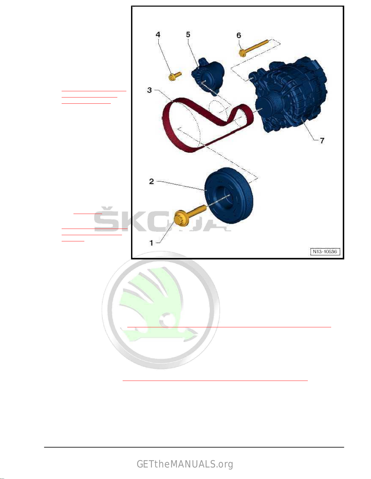
Protected by copyright. Copying for private or commercial purposes, in part or in whole, is not permitted
unless authorised by ŠKODA AUTO A. S. ŠKODA AUTO A. S. does not guarantee or accept any liability
with respect to the correctness of information in this document. Copyright by ŠKODA AUTO A. S.�
1 - Screw
GETtheMANUALS.org
❑ Replace after disas‐
sembly
❑
to release and tighten
use counterholder T10475-
❑ 150 Nm + 180°
2 - Vibration damper
❑ with vibration damper
❑ removing and installing
⇒ “1.5 Installing and re‐
moving the vibration
damper”, page 43
3 - V-ribbed belt
❑ check for wear
❑
mark the direction of ro‐
tation with chalk or a felt-
tip pen before removing
❑ do not kink
❑ depending on the model
of the belt pulley for al‐
ternator, the correct
length of the V-ribbed
belt must be assigned ⇒
ETKA - Electronic Cata‐
logue of Original Parts
❑ Routing of the ribbed V-
⇒ page 41
belt
❑ removing and installing
⇒ “1.3 Removing and in‐
stalling V-ribbed belt”,
page 41
❑ pay attention to the cor‐
rect position on the belt
pulley when installing it.
4 - Screw
❑
Replace after disassembly
❑ 20 Nm + 90°
5 - Swivel tensioning pulley for poly V-belt
❑ swivel with socket to slacken the V-ribbed belt
❑ lock with locking pin - T10060 A❑ removing and installing
⇒ “1.4 Removing and installing tensioner pulley for ribbed V-belt”, page 43
6 - Screw
❑ 23 Nm
7 - Generator
❑
Removing and installing ⇒ Electrical system; Rep. gr. 27 ; Alternator; Removing and installing alternator .
❑ Depending on the model of the alternator, different separation ribbed V-belt pulleys can be fitted with
freewheel -A- and -B❑ depending on the model of the belt pulley for alternator, the correct length of the ribbed V-belt must be
⇒ Fig. ““Model of the V-ribbed belt pulley with freewheel”“ , page 38
assigned ⇒ ETKA - Electronic Catalogue of Original Parts
1. Cylinder block (pulley end) 37
Page 44

Protected by copyright. Copying for private or commercial purposes, in part or in whole, is not permitted
unless authorised by ŠKODA AUTO A. S. ŠKODA AUTO A. S. does not guarantee or accept any liability
with respect to the correctness of information in this document. Copyright by ŠKODA AUTO A. S.�
Model of the V-ribbed belt pulley with freewheel
GETtheMANUALS.org
1.1.2 Summary of components - Vehicles with air conditioning
1 - V-ribbed belt
❑ check for wear
❑
mark the direction of ro‐
tation with chalk or a felt-
tip pen before removing
❑ do not kink
❑ depending on the model
of the belt pulley for al‐
ternator, the correct
length of the V-ribbed
belt must be assigned ⇒
ETKA - Electronic Cata‐
logue of Original Parts
❑ Routing of the ribbed V-
❑ removing and installing
❑ pay attention to the cor‐
2 - Screw
❑
❑ to release and tighten
❑ 150 Nm + 180°
3 - Vibration damper
❑ with vibration damper
❑ removing and installing
⇒ page 42
belt
⇒ “1.3.1 Removing and
installing V-ribbed belt -
Vehicles without air con‐
ditioning”, page 41
rect position on the belt
pulley when installing it.
Replace after disas‐
sembly
use counterholder -
T10475-
⇒ “1.5 Installing and re‐
moving the vibration
damper”, page 43
38 Rep. gr.13 - Crankshaft group
Page 45

Protected by copyright. Copying for private or commercial purposes, in part or in whole, is not permitted
unless authorised by ŠKODA AUTO A. S. ŠKODA AUTO A. S. does not guarantee or accept any liability
with respect to the correctness of information in this document. Copyright by ŠKODA AUTO A. S.�
4 - Swivel tensioning pulley for poly V-belt
GETtheMANUALS.org
❑ swivel with socket to slacken the V-ribbed belt
❑
lock with locking pin - T10060 A-
❑ removing and installing
⇒ “1.4 Removing and installing tensioner pulley for ribbed V-belt”, page 43
5 - Screw
❑ 20 Nm + 90°
6 - Screw
❑
23 Nm
7 - Generator
❑ Removing and installing ⇒ Electrical system; Rep. gr. 27 ; Alternator; Removing and installing alternator .
❑ Depending on the model of the alternator, different separation ribbed V-belt pulleys can be fitted with
freewheel -A- and -B-
⇒ Fig. ““Model of the V-ribbed belt pulley with freewheel”“ , page 39
❑ depending on the model of the belt pulley for alternator, the correct length of the V-ribbed belt must be
assigned ⇒ ETKA - Electronic Catalogue of Original Parts
8 - Fitting sleeve
❑
for the AC compressor
9 - AC compressor
❑ Do not unscrew or disconnect refrigerant lines
❑ installing and removing ⇒ Heating, Air Conditioning; Rep. gr. 87 ; AC compressor; installing and re‐
moving AC compressor
10 - Screw
❑ Tightening torque ⇒ Heating, Air Conditioning; Rep. gr. 87 ; AC compressor; installing and removing
AC compressor
Model of the V-ribbed belt pulley with freewheel
1. Cylinder block (pulley end) 39
Page 46

Protected by copyright. Copying for private or commercial purposes, in part or in whole, is not permitted
unless authorised by ŠKODA AUTO A. S. ŠKODA AUTO A. S. does not guarantee or accept any liability
with respect to the correctness of information in this document. Copyright by ŠKODA AUTO A. S.�
1.2 Summary of components - sealing flange on the belt pulley side
GETtheMANUALS.org
1 - Screw
❑ Replace after disas‐
sembly
❑
to release and tighten
use counterholder -
T10475❑ Tightening torque
⇒ “1.1 Assembly over‐
view - ribbed V-belt
drive”, page 36
2 - Vibration damper
❑ with vibration damper
❑
removing and installing
⇒ “1.5 Installing and re‐
moving the vibration
damper”, page 43
3 - Sealing ring
❑ for crankshaft on the
belt pulley side
❑
replace after removal
⇒ “1.7 Replacing crank‐
shaft sealing ring - belt
pulley end”, page 48
❑ do not oil
4 - Sealing flange on the belt
pulley side
❑
must be positioned on
dowel pins
❑ removing and installing
⇒ “1.8 Removing and in‐
stalling the sealing
flange on the belt pulley
side”, page 50
5 - Screw
❑ Different diameters⇒ ETKA - Electronic Catalogue of Original Parts
❑
Replace after disassembly
❑ Tightening torque and tightening order
⇒ Fig. ““Sealing flange on the belt pulley side - tightening torque and tightening order”“ , page 41
6 - Gasket
❑ Replace after disassembly
7 - Cylinder block
❑
After replacing, fill with fresh coolant
8 - Fit pin
❑ 2 pieces
9 - Screw
❑
Replace after disassembly
❑ Tightening torque and tightening order
⇒ “1.3 Draining and filling up coolant”, page 225
⇒ “1.1 Assembly overview - sump/oil pump”, page 195
40 Rep. gr.13 - Crankshaft group
Page 47

Protected by copyright. Copying for private or commercial purposes, in part or in whole, is not permitted
unless authorised by ŠKODA AUTO A. S. ŠKODA AUTO A. S. does not guarantee or accept any liability
with respect to the correctness of information in this document. Copyright by ŠKODA AUTO A. S.�
Sealing flange on the belt pulley side - tightening torque and tight‐
GETtheMANUALS.org
ening order
– Tighten screws gradually:
Stage Screws Tightening torque/torquing angle
1. -1…12- by hand as far as the stop
2. -1…12- crosswise to 8 Nm
3. -7-, -8- 20 Nm
4. -1…12- Turn 90° further
1.3 Removing and installing V-ribbed belt
⇒ “1.3.1 Removing and installing V-ribbed belt - Vehicles without
air conditioning”, page 41
⇒ “1.3.2 Removing and installing V-ribbed belt - Vehicles with air
conditioning”, page 42
1.3.1 Removing and installing V-ribbed belt Vehicles without air conditioning
Special tools and workshop equipment required
♦ Locking pin - T10060 ARemoving
– Remove the sound dampening system ⇒ General body re‐
pairs, exterior ; Rep. gr. 66 ; Noise insulation; Summary of
components - noise insulation .
– Swing the tensioning pulley in -direction of arrow- to detension
the V-ribbed belt.
–
Lock tensioning pulley with locking pin - T10060 A- .
Note
There is a risk of destruction through reversing the rotation direc‐
tion of an already used V-ribbed belt.
– Mark the direction of rotation with chalk or a felt-tip pen on the
V-ribbed belt for re-installation before removing the V-ribbed
belt.
– Remove the ribbed V-belt.
Install
Installation is performed in the reverse order, pay attention to the
following points:
– Lay the V-ribbed belt as shown in the illustration.
1 - Ribbed V-belt pulley
2 - Swivel tensioning pulley for poly V-belt
3 - Generator
1. Cylinder block (pulley end) 41
Page 48

Protected by copyright. Copying for private or commercial purposes, in part or in whole, is not permitted
unless authorised by ŠKODA AUTO A. S. ŠKODA AUTO A. S. does not guarantee or accept any liability
with respect to the correctness of information in this document. Copyright by ŠKODA AUTO A. S.�
– Turn the tensioning pulley in -direction of arrow- and pull out
GETtheMANUALS.org
the locking pin - T10060A- .
– Release tension on tensioning pulley.
– Check that the poly V-belt is positioned correctly.
– Start end and check that the V-ribbed belt is running correctly.
Tightening torques
♦
Noise insulation ⇒ General body repairs, exterior ; Rep. gr.
66 ; Noise insulation; Summary of components - noise insu‐
lation.
1.3.2 Removing and installing V-ribbed belt -
Vehicles with air conditioning
Special tools and workshop equipment required
♦ Locking pin - T10060 ARemoving
– Remove the sound dampening system ⇒ General body re‐
pairs, exterior ; Rep. gr. 66 ; Noise insulation; Summary of
components - noise insulation .
– Swing the tensioning pulley in -direction of arrow- to detension
the V-ribbed belt.
– Lock tensioning pulley with locking pin - T10060 A- .
Note
There is a risk of destruction through reversing the rotation direc‐
tion of an already used V-ribbed belt.
– Mark the direction of rotation with chalk or a felt-tip pen on the
V-ribbed belt for re-installation before removing the V-ribbed
belt.
– Remove the ribbed V-belt.
Install
Installation is performed in the reverse order, pay attention to the
following points:
– Lay the V-ribbed belt as shown in the illustration:
1 - Ribbed V-belt pulley
2 - Swivel tensioning pulley for poly V-belt
3 - Generator
4 - AC compressor
42 Rep. gr.13 - Crankshaft group
Page 49

Protected by copyright. Copying for private or commercial purposes, in part or in whole, is not permitted
unless authorised by ŠKODA AUTO A. S. ŠKODA AUTO A. S. does not guarantee or accept any liability
with respect to the correctness of information in this document. Copyright by ŠKODA AUTO A. S.�
– Turn the tensioning pulley in -direction of arrow- and pull out
GETtheMANUALS.org
the locking pin - T10060A- .
– Release tension on tensioning pulley.
– Check that the poly V-belt is positioned correctly.
– Start end and check that the V-ribbed belt is running correctly.
Tightening torques
♦
Noise insulation ⇒ General body repairs, exterior ; Rep. gr.
66 ; Noise insulation; Summary of components - noise insu‐
lation.
1.4 Removing and installing tensioner pul‐
ley for ribbed V-belt
Removing
– Remove the V-ribbed belt from the tensioning device
⇒ “1.3 Removing and installing V-ribbed belt”, page 41 .
– Unscrew screws -arrows- and pull off tensioning pulley -1- for
V-ribbed belt.
Install
Installation is performed in the reverse order, pay attention to the
following points:
– Install the V-ribbed belt
⇒ “1.3 Removing and installing V-ribbed belt”, page 41 .
Tightening torques
♦ Tensioning pulley
⇒ “1.1 Assembly overview - ribbed V-belt drive”, page 36 .
1.5 Installing and removing the vibration
damper
Special tools and workshop equipment required
♦ Counterholder - T10475Removing
– Remove the sound dampening system ⇒ General body re‐
pairs, exterior ; Rep. gr. 66 ; Noise insulation; Summary of
components - noise insulation .
– Remove V-ribbed belt
⇒ “1.3 Removing and installing V-ribbed belt”, page 41 .
Note
♦
Two versions of the vibration dampers may be available, which
differ in terms of the position of the holes for the vibration
damper's catch.
♦
If the counterholder - T10475- cannot be position on the vi‐
bration damper, the counterholder must be adjusted.
1. Cylinder block (pulley end) 43
Page 50

Protected by copyright. Copying for private or commercial purposes, in part or in whole, is not permitted
unless authorised by ŠKODA AUTO A. S. ŠKODA AUTO A. S. does not guarantee or accept any liability
with respect to the correctness of information in this document. Copyright by ŠKODA AUTO A. S.�
Adjust counterholder - T10475-
GETtheMANUALS.org
– Unscrew the support pin - T10475/1- -2- from the counter‐
holder - T10475- .
– Unscrew the vibration damper holding pin -1- from the coun‐
terholder -
- T10475/1- -2-.
Position the counterholder - T10475- on the vibration damper –
version 1
T10475- and screw into the hole for the support pin
Position the adjusted counterholder - T10475- on the vibration
damper – version 2
Continue removal
– Loosen screw -arrow- for vibration damper; to do so, use
counterholder - T10475- .
– Unscrew screw and remove vibration damper.
NOTICE
Risk of destruction of the engine.
♦ So as not to adjust the timing the crankshaft must not be turned
while the vibration damper is removed.
Install
Note
All contact surfaces between screws, vibration damper and crank‐
shaft pulley must be free of oil and grease.
Installation is carried out in the reverse order. When installing,
note the following:
– Install the V-ribbed belt
⇒ “1.3 Removing and installing V-ribbed belt”, page 41 .
Tightening torques
♦ Screw for vibration damper
⇒ “1.1 Assembly overview - ribbed V-belt drive”, page 36 .
44 Rep. gr.13 - Crankshaft group
Page 51

Protected by copyright. Copying for private or commercial purposes, in part or in whole, is not permitted
unless authorised by ŠKODA AUTO A. S. ŠKODA AUTO A. S. does not guarantee or accept any liability
with respect to the correctness of information in this document. Copyright by ŠKODA AUTO A. S.�
1.6 Removing and installing engine support
GETtheMANUALS.org
Removing
– Remove battery
27 ; Battery; Removing and installing battery .
– Loosen hose clamps -1- and -2- and remove air guide pipe.
– Remove air filter housing
⇒ “3.2 Removing and installing air filter housing”, page 302 .
– Remove tensioning pulley for V-ribbed belt
⇒ “1.4 Removing and installing tensioner pulley for ribbed V-
belt”, page 43 .
– Unclip holder -3- together with hoses from the toothed belt
guard -1-.
– Unscrew bolt -2-.
– Loosen clips -arrows- and remove toothed belt guard -1- up‐
wards.
and battery tray ⇒ Electrical system; Rep. gr.
– Unscrew bolt -1-.
1. Cylinder block (pulley end) 45
Page 52

Protected by copyright. Copying for private or commercial purposes, in part or in whole, is not permitted
unless authorised by ŠKODA AUTO A. S. ŠKODA AUTO A. S. does not guarantee or accept any liability
with respect to the correctness of information in this document. Copyright by ŠKODA AUTO A. S.�
– Unscrew screws
GETtheMANUALS.org
-2-.
CAUTION
Risk of injury caused by fuel which is under high pressure.
Lay a clean cloth around the connection point and carefully slack‐
en
connection point in order to relieve the pressure in the fuel
the
system.
-1- and remove the catalytic converter holder
NOTICE
Risk of malfunctions caused by soiling.
Observe safety measures and rules for cleanliness
⇒ “3.1 Cleanliness rules”, page 6 .
– Separate fuel feed line -1- and the line to activated charcoal
filter -2-.
– Disconnect plug connection -1-.
– Unclip holder -2- with hoses from the expansion tank and place
to one side.
Unlock catches using a screwdriver -arrow- and lay coolant
–
expansion tank to the side.
– Open holding clamps on the air conditioning system pipes.
– Loosen screw -1- but do not unscrew it.
– Unscrew bolt -2-.
– Swivel generator -3- forward in -direction of the arrow-.
46 Rep. gr.13 - Crankshaft group
Page 53

Protected by copyright. Copying for private or commercial purposes, in part or in whole, is not permitted
unless authorised by ŠKODA AUTO A. S. ŠKODA AUTO A. S. does not guarantee or accept any liability
with respect to the correctness of information in this document. Copyright by ŠKODA AUTO A. S.�
– Release screws -arrows-.
GETtheMANUALS.org
– Remove pendulum support
⇒ “2.4 Removing and installing pendulum support”, page 30 .
– Suspend engine into the installation position
⇒ “2.5 Support the engine in its installed position”, page 31 .
– Remove engine mounts
⇒ “2.2 Removing and installing engine mount”, page 28 .
– Release screws -arrows-.
– Unscrew screws -1-, -2-, -3-.
Gearbox mount with 2 screws
– Release screws -arrows-.
1. Cylinder block (pulley end) 47
Page 54

Protected by copyright. Copying for private or commercial purposes, in part or in whole, is not permitted
unless authorised by ŠKODA AUTO A. S. ŠKODA AUTO A. S. does not guarantee or accept any liability
with respect to the correctness of information in this document. Copyright by ŠKODA AUTO A. S.�
Gearbox mount with 3 screws
GETtheMANUALS.org
– Release screws -arrows-.
Continued for all vehicles
– Push the engine/gearbox assembly slightly to the left and
front.
– Remove engine support bracket.
Install
Installation is performed in the reverse order, pay attention to the
following points:
– Check assembly bracket setting
⇒ “2.7 Check assembly bracket setting”, page 35 .
Tightening torques
♦ Assembly bracket
⇒ “2.1 Assembly overview - assembly mountings”, page 26 .
♦ Tensioning pulley for V-ribbed belt
⇒ “1.1 Assembly overview - ribbed V-belt drive”, page 36 .
♦ Engine support bracket
⇒ “2.1 Summary of components - toothed belt guard”,
page 91 .
♦ Toothed belt guard
⇒ “2.1 Summary of components - toothed belt guard”,
page 91 .
♦ Fixing screws for generator ⇒ Electrical system; Rep. gr. 27 ;
Generator; Removing and installing generator.
♦ Coolant pipes
⇒ “3.1 Summary of components - coolant pipe”, page 248 .
♦ Removing and installing parts of the exhaust system
⇒ “2.1 Summary of components - exhaust gas cleaning”, page
348 .
1.7 Replacing crankshaft sealing ring - belt
pulley end
Special tools and workshop equipment required
♦ Assembly device - T10485♦ Extractor - T20143Work procedure
– Remove toothed belt
⇒ “2.3 Removing and installing toothed belt”, page 95 .
– Remove crankshaft toothed belt pulley -1- -arrow-.
48 Rep. gr.13 - Crankshaft group
Page 55
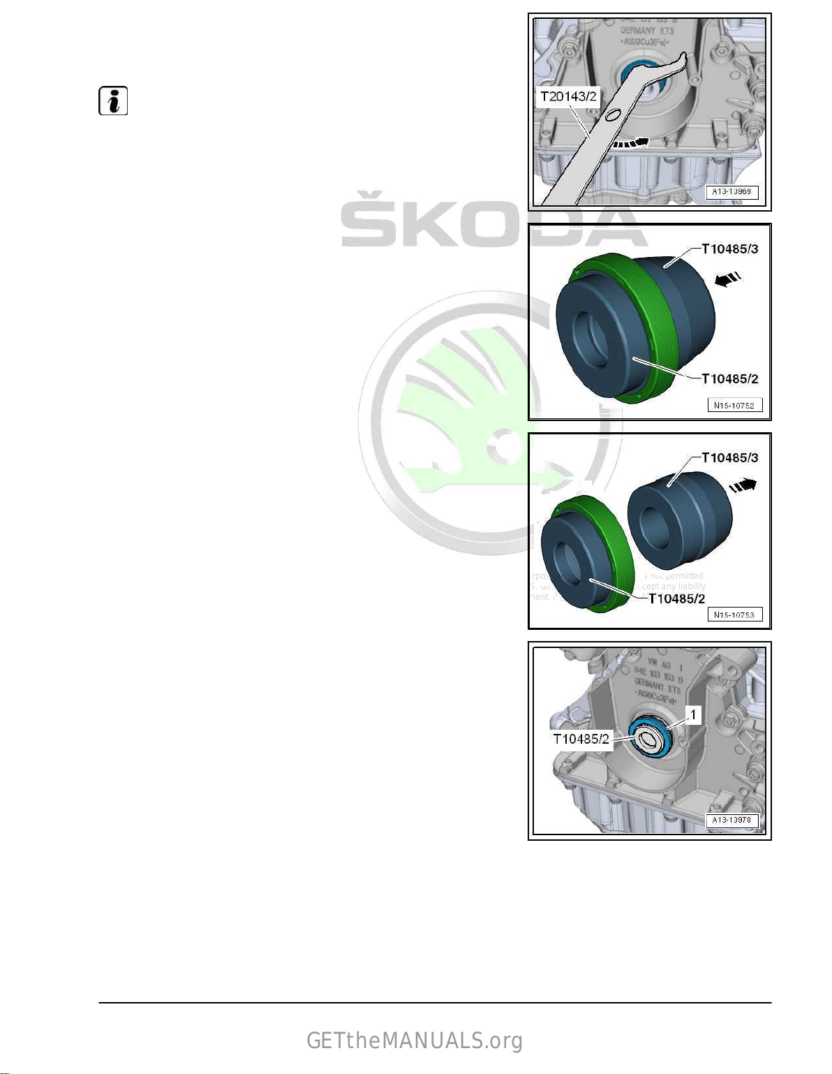
Protected by copyright. Copying for private or commercial purposes, in part or in whole, is not permitted
unless authorised by ŠKODA AUTO A. S. ŠKODA AUTO A. S. does not guarantee or accept any liability
with respect to the correctness of information in this document. Copyright by ŠKODA AUTO A. S.�
– Lift out sealing ring using the extractor hook -T20143/2-
GETtheMANUALS.org
-arrow-.
– Clean the contact and sealing surfaces.
Note
Do not oil new sealing ring.
– Push new sealing ring in -direction of the arrow- over the as‐
sembly sleeve - T10485/3- onto the assembly sleeve T10485/2- .
• Fitting position: Closed side of sealing ring points to the re‐
ceiver tube.
– Pull off assembly sleeve - T10485/3- in -direction of arrow-.
– Fit guide bushing -T10485/2- with seal -1- onto crankshaft
journal.
1. Cylinder block (pulley end) 49
Page 56

Protected by copyright. Copying for private or commercial purposes, in part or in whole, is not permitted
unless authorised by ŠKODA AUTO A. S. ŠKODA AUTO A. S. does not guarantee or accept any liability
with respect to the correctness of information in this document. Copyright by ŠKODA AUTO A. S.�
– Pull sealing ring -2- in to the stop using the thrust piece -
GETtheMANUALS.org
T10485/1- and the belt pulley screw -1-.
– Fit crankshaft toothed belt pulley onto the crankshaft.
• The contact surface between the V-ribbed belt pulley crank‐
shaft and crankshaft toothed belt sprocket must be free of oil
and grease.
• Milled surface -arrow- on the crankshaft toothed belt must be
positioned on the crankshaft stub.
– install (set the timing) ⇒ page 104 .
1.8 Removing and installing the sealing
Special tools and workshop equipment required
♦ Cleaning and degreasing agent , e.g. -D 009 401 04Removing
– Remove toothed belt
⇒ “2.3 Removing and installing toothed belt”, page 95 .
– Remove crankshaft toothed belt pulley -1- -arrow-.
– Remove sump top part
⇒ “1.4 Removing and installing oil sump top part”, page 202 .
flange on the belt pulley side
50 Rep. gr.13 - Crankshaft group
Page 57
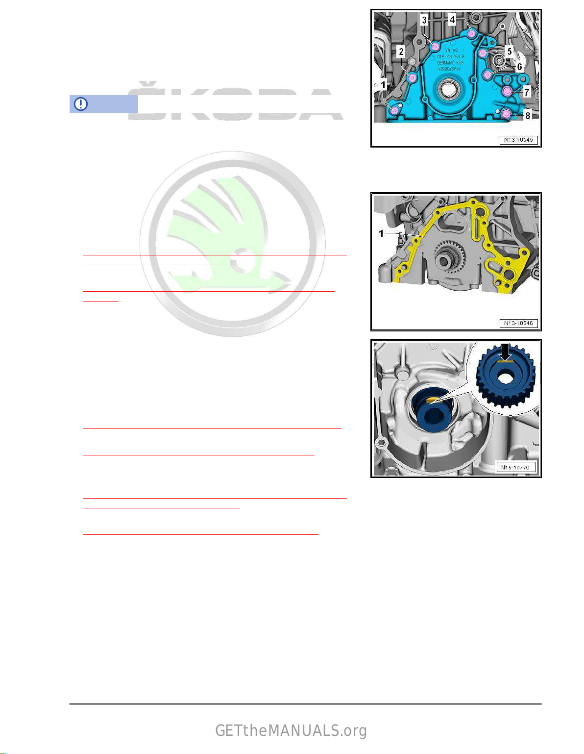
Protected by copyright. Copying for private or commercial purposes, in part or in whole, is not permitted
unless authorised by ŠKODA AUTO A. S. ŠKODA AUTO A. S. does not guarantee or accept any liability
with respect to the correctness of information in this document. Copyright by ŠKODA AUTO A. S.�
– Unscrew the
GETtheMANUALS.org
screws -1- to -8- and carefully loosen the sealing
flange from the bonding.
– Drive out the gasket ring from the removed sealing flange.
Install
Installation is performed in the reverse order, pay attention to the
following points:
NOTICE
Risk of contamination of the lubrication system by sealant res‐
idues.
– Remove sealant residues from the cylinder block.
– Clean oil and grease from sealing surfaces.
– Push gasket -1- onto the dowel pins on the cylinder block.
– Carefully push sealing flange onto the dowel pins on the cyl‐
inder block.
– Tighten sealing flange screws
⇒ Fig. ““Sealing flange on the belt pulley side - tightening tor‐
que and tightening order”“ , page 41 .
– Install the gasket ring for the crankshaft -belt pulley side
⇒ “1.7 Replacing crankshaft sealing ring - belt pulley end”,
page 48 .
– Fit crankshaft toothed belt pulley onto the crankshaft.
• The contact surface between the V-ribbed belt pulley and the
crankshaft toothed belt pulley must be free of oil and grease.
• Milled surface -arrow- on the crankshaft toothed belt must be
positioned on the crankshaft stub.
– Install sump top part
⇒ “1.4 Removing and installing oil sump top part”, page 202 .
– install (set the timing)
⇒ “2.3 Removing and installing toothed belt”, page 95 .
Tightening torques
♦ Sealing flange on the belt pulley side
⇒ Fig. ““Sealing flange on the belt pulley side - tightening tor‐
que and tightening order”“ , page 41 .
♦ Sump top part
⇒ “1.1 Assembly overview - sump/oil pump”, page 195 .
1. Cylinder block (pulley end) 51
Page 58
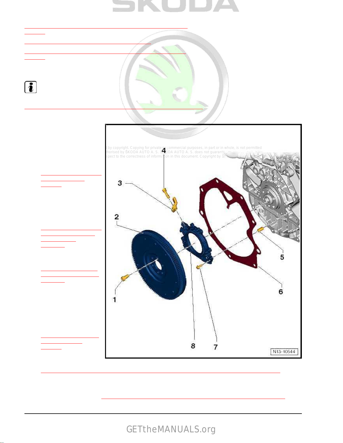
Protected by copyright. Copying for private or commercial purposes, in part or in whole, is not permitted
unless authorised by ŠKODA AUTO A. S. ŠKODA AUTO A. S. does not guarantee or accept any liability
with respect to the correctness of information in this document. Copyright by ŠKODA AUTO A. S.�
2 Cylinder block on gearbox side
GETtheMANUALS.org
⇒ “2.1 Summary of components - cylinder block on gearbox side”,
page 52
⇒ “2.2 Removing and installing flywheel”, page 53
⇒ “2.3 Removing and installing sealing flange on gearbox side”,
page 54
2.1 Summary of components - cylinder block on gearbox side
Note
For assembly work, secure the engine to the engine and gearbox support -VAS 6095-
⇒ “1.3 Attach engine attached to engine and gearbox mount”, page 20 .
1 - Screw
❑ Replace after disas‐
sembly
❑ 60 Nm + 90°
2 - Flywheel
❑ removing and installing
⇒ “2.2 Removing and in‐
stalling flywheel”,
page 53
❑ can be installed only in
one position
3 - Engine speed sender G28-
removing and installing
❑
⇒ “1.5 Removing and in‐
stalling engine speed
sender G28 ”,
page 365
4 - Screw
❑ Tightening torque
⇒ “1.1 Assembly over‐
view - ignition system”,
page 360
5 - Fit pin
❑ 2 pieces
6 - Intermediate plate
do not damage/bend
❑
during assembly work
❑ installing
⇒ Fig. ““Installing inter‐
mediate plate”“ ,
page 53
7 - Screw
❑ Tightening torque and tightening order
⇒ Fig. ““Sealing flange on the gearbox side - tightening torque and tightening order”“ , page 53
8 - Sealing flange with sender wheel and oil seal
❑ Replace sealing flange complete with oil seal and sender wheel only
removing and installing
❑
⇒ “2.3 Removing and installing sealing flange on gearbox side”, page 54
52 Rep. gr.13 - Crankshaft group
Page 59

Protected by copyright. Copying for private or commercial purposes, in part or in whole, is not permitted
unless authorised by ŠKODA AUTO A. S. ŠKODA AUTO A. S. does not guarantee or accept any liability
with respect to the correctness of information in this document. Copyright by ŠKODA AUTO A. S.�
Sealing flange on the gearbox side - tightening torque and tight‐
GETtheMANUALS.org
ening order
– Tighten screws in steps as follows:
Stage Screws Specified torque
1. -1 … 6- by hand as far as the stop
2. -1 … 6- tighten crosswise in steps up to 10 Nm
Installing intermediate plate
– Mount intermediate plate -1- on sealing flange arrow -B- and
push onto the dowel sleeves arrows -A-.
2.2 Removing and installing flywheel
Special tools and workshop equipment required
♦ Counterholder - MP1-223 (3067)Removing
• Gearbox removed.
– Remove clutch in vehicles with manual gearbox ⇒ Rep. gr.
30 ; Clutch; removing and installing clutch .
• Fitting position of the tool:
A - for tightening
B - for slackening
– Insert the counterholder - 3067- into the hole on the cylinder
block -B-.
– Loosen and remove all flywheel bolts.
Install
Installation is performed in the reverse order, pay attention to the
following points:
Note
Assembly of flywheel with rotor is only possible in one position.
– Insert the counterholder - 3067- into the hole on the cylinder
block -A-.
Tightening torques
♦ Flywheel to crankshaft
⇒ “2.1 Summary of components - cylinder block on gearbox
side”, page 52 .
2. Cylinder block on gearbox side 53
Page 60
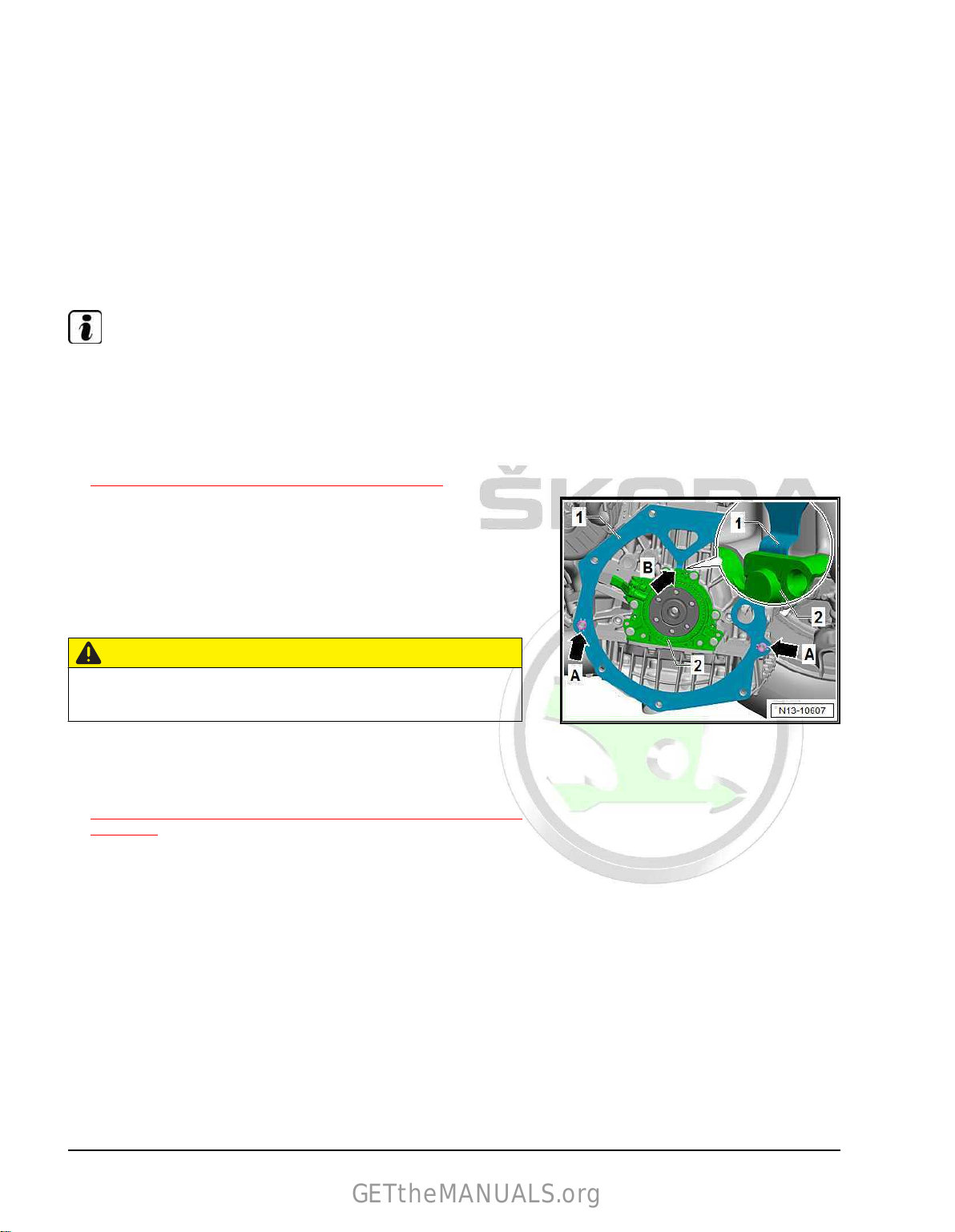
Protected by copyright. Copying for private or commercial purposes, in part or in whole, is not permitted
unless authorised by ŠKODA AUTO A. S. ŠKODA AUTO A. S. does not guarantee or accept any liability
with respect to the correctness of information in this document. Copyright by ŠKODA AUTO A. S.�
2.3 Removing and installing sealing flange
GETtheMANUALS.org
on gearbox side
Special tools and workshop equipment required
♦ Depth gauge - VAS 6082♦ Assembly device - T10134♦ Locating screw - T10340♦ 3x screw M6x35.
Work procedure
• Gearbox is removed ⇒ Rep. gr. 34 ; Installing and removing
gearbox; remove gearbox ⇒ Rep. gr. 34 or ⇒ Rep. gr. 34 ;
installing and removing gearbox; removing gearbox .
Note
♦
For reasons of clarity, the work was performed with the engine
removed.
♦
The procedure is identical whether the engine is installed or
removed.
– Remove the flywheel
⇒ “2.2 Removing and installing flywheel”, page 53 .
– Remove intermediate
-A-.
– Move intermediate plate -1- upwards.
– At the same time, pull the retaining lug arrow -B- of the inter‐
mediate plate -1- out of the recess behind the sealing flange.
Position crankshaft to “TDC”:
plate -1- from the dowel sleeves arrows
CAUTION
Risk of engine damage.
You must adjust the “TDC” position, as described!
♦ Locating screw - T10340- can collide with crankshaft in two
positions.
– Remove ignition coil with power output stage 1
⇒ “1.2 Removing and installing ignition coils with output stage”,
page 361 .
– Remove ignition plug cylinder 1 with spark plug socket
wrench , e. g. -3122 B- .
54 Rep. gr.13 - Crankshaft group
Page 61
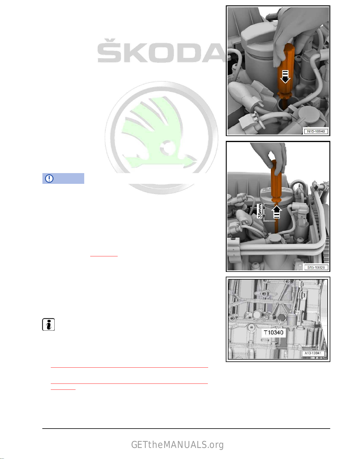
Protected by copyright. Copying for private or commercial purposes, in part or in whole, is not permitted
unless authorised by ŠKODA AUTO A. S. ŠKODA AUTO A. S. does not guarantee or accept any liability
with respect to the correctness of information in this document. Copyright by ŠKODA AUTO A. S.�
Set the correct position of the crankshaft for screwing in the lo‐
GETtheMANUALS.org
cating screw:
– Carefully insert a screwdriver into the opening of the ignition
plug, minimum length of shaft 250 mm, in -direction of arrowso that it touches the piston head.
– Rotate the crankshaft in direction of rotation of engine on
“TDC” for cylinder 1.
– Turn engine shaft further in direction of arrow so that the
screwdriver just out at the top by approx 35 mm in the
-direction of the arrow-.
– Unscrew screw plug “TDC” bore at the cylinder block.
NOTICE
Risk of damage to the engine if the locating screw - T10340- is
screwed in at the wrong position.
If the locating screw - T10340- cannot be screwed in up to the
stop, the crankshaft is not in the correct position.
In this case, proceed as follows:
– Unscrew locking pin.
– Set the correct position of the crankshaft for screwing in the
locating screw
⇒ page 55 .
– Screw the locating screw - T10340- up to the stop into the
cylinder block and tighten to 30 Nm.
– Turn crankshaft up to the stop in direction of rotation of engine.
The crankshaft cheek is now resting on the locating screw .
•
Note
The crankshaft is only locked in direction of rotation of engine
using the locating screw - T10340- .
– Remove sump top part
⇒ “1.4 Removing and installing oil sump top part”, page 202 .
– Remove engine speed transmitter - G28-
⇒ “1.5 Removing and installing engine speed sender G28 ”,
page 365 .
2. Cylinder block on gearbox side 55
Page 62

Protected by copyright. Copying for private or commercial purposes, in part or in whole, is not permitted
unless authorised by ŠKODA AUTO A. S. ŠKODA AUTO A. S. does not guarantee or accept any liability
with respect to the correctness of information in this document. Copyright by ŠKODA AUTO A. S.�
– Unscrew locating screw s on the sealing flange -arrows-.
GETtheMANUALS.org
– Sealing flange and rotor are pressed together with 3 M6x35
mm screws from the crankshaft.
–
Alternating, screw in three screws -arrows- (max. 1/2 turn
(180°) per screw) into the threaded holes of the sealing flange
-1- and remove the sealing flange together with the rotor -2from the crankshaft -3-.
Sealing flange with rotor
Note
♦
The sealing flange with PTFE gasket ring is provided with
sealing lip supporting ring -2-. This support ring serves as a
fitting sleeve and must not be removed prior to installation.
♦
Do not separate or turn the sealing flange and rotor -1- after
removing them from the spare part package.
♦
The rotor is given its fitting location by fixing the assembly tool
- T10134- to the positioning pin.
♦
Sealing flange and oil seal form one unit and must only be
replaced together with the sender wheel.
♦
The rotor has an elastomer layer on its sealing surface for the
crankshaft. This layer must not be brought into contact with
dirt or grease.
♦
The assembly tool - T10134- is given its fitting location to the
crankshaft by means of a guide bolt, which is guided into the
threaded bore of the crankshaft.
56 Rep. gr.13 - Crankshaft group
Page 63

Protected by copyright. Copying for private or commercial purposes, in part or in whole, is not permitted
unless authorised by ŠKODA AUTO A. S. ŠKODA AUTO A. S. does not guarantee or accept any liability
with respect to the correctness of information in this document. Copyright by ŠKODA AUTO A. S.�
Assembly tool - T10134-
GETtheMANUALS.org
A - Clamping surface
B - Hexagon nut
C - Assembly housing
D - Locating pin
E - Allan screws (2 pieces)
F - Guide bolts for petrol engines
G - Guide bolts for diesel engines
H - Knurled screws (3 pieces)
I - Inner part
A - Attach sealing flange with rotor to the assembly tool - T10134-
– Screw on nut -B- until
just before it touches the clamping sur‐
face -A- of the threaded spindle.
– Grip assembly tool - T10134- at clamping surface -A- of the
threaded spindle in a vice.
– Press assembly housing -C- downwards until it lies on hexa‐
gon nut -B-.
– Screw nut onto threaded spindle until inner part of assembly
tool and assembly housing are at same height.
– Remove the
Note
Do not remove or turn the rotor from the sealing flange.
securing clip -arrow- from the new sealing flange.
2. Cylinder block on gearbox side 57
Page 64
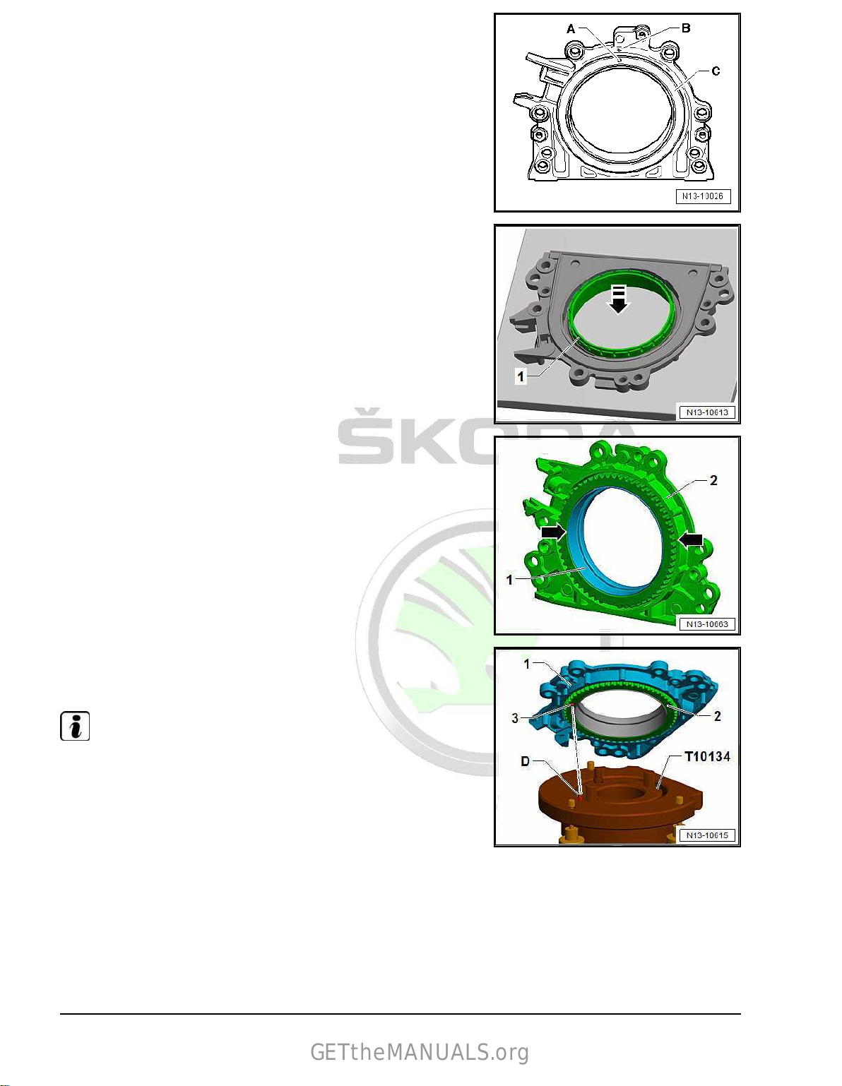
Protected by copyright. Copying for private or commercial purposes, in part or in whole, is not permitted
unless authorised by ŠKODA AUTO A. S. ŠKODA AUTO A. S. does not guarantee or accept any liability
with respect to the correctness of information in this document. Copyright by ŠKODA AUTO A. S.�
• Locating hole -A- on
GETtheMANUALS.org
-B- on sealing flange.
– Place sealing flange with front side facing down on a clean
level surface.
– Press down sealing lips supporting ring -1- in
-direction of the arrow-, until it rests on the level surface.
sender wheel -C- must align with marking
• Upper edge of sealing lip support ring -1- and front edge of
sealing flange -2- must align -arrows-.
– Lay
the sealing flange -1- with the front side onto the assembly
tool - T10134- in such a way that the positioning pin
gages into the hole -3- of the sender wheel -2-.
Note
-D- en‐
Sealing flange must lie straight on the assembly tool.
58 Rep. gr.13 - Crankshaft group
Page 65

Protected by copyright. Copying for private or commercial purposes, in part or in whole, is not permitted
unless authorised by ŠKODA AUTO A. S. ŠKODA AUTO A. S. does not guarantee or accept any liability
with respect to the correctness of information in this document. Copyright by ŠKODA AUTO A. S.�
– Press on the sealing flange -1- and sealing lip supporting ring
GETtheMANUALS.org
-2- by tightening the 3 knurled screws
-H- onto the surface of
the assembly tool - T10134- .
Note
This prevents locating pin from slipping out of sender wheel hole.
– When installing the sealing flange, ensure that the sender
wheel remains fixed in the assembly device.
B - secure assembly tool - T10134- with sealing flange onto the
crankshaft flange and cylinder block
• Crankshaft flange free from oil and grease.
• The engine is at “TDC”.
– Screw nut -B- on until it reaches end of threaded spindle.
– Press the threaded spindle on the assembly tool - T10134- in
-direction of arrow- until the nuts -B- rest against the assembly
cup -C-.
– Align flat side of assembly housing to the cylinder block sealing
surface on the oil sump side.
– Secure the assembly tool - T10134- and the sealing flange
-1- with Allan screws -E- to the crankshaft flange.
Note
Screw in Allan screws -E- into the crankshaft flange by approx.
five thread turns.
– Screw
in two M6x35 mm screws -2- by about 3 turns for sealing
flange guide
-1- into the cylinder block.
2. Cylinder block on gearbox side 59
Page 66
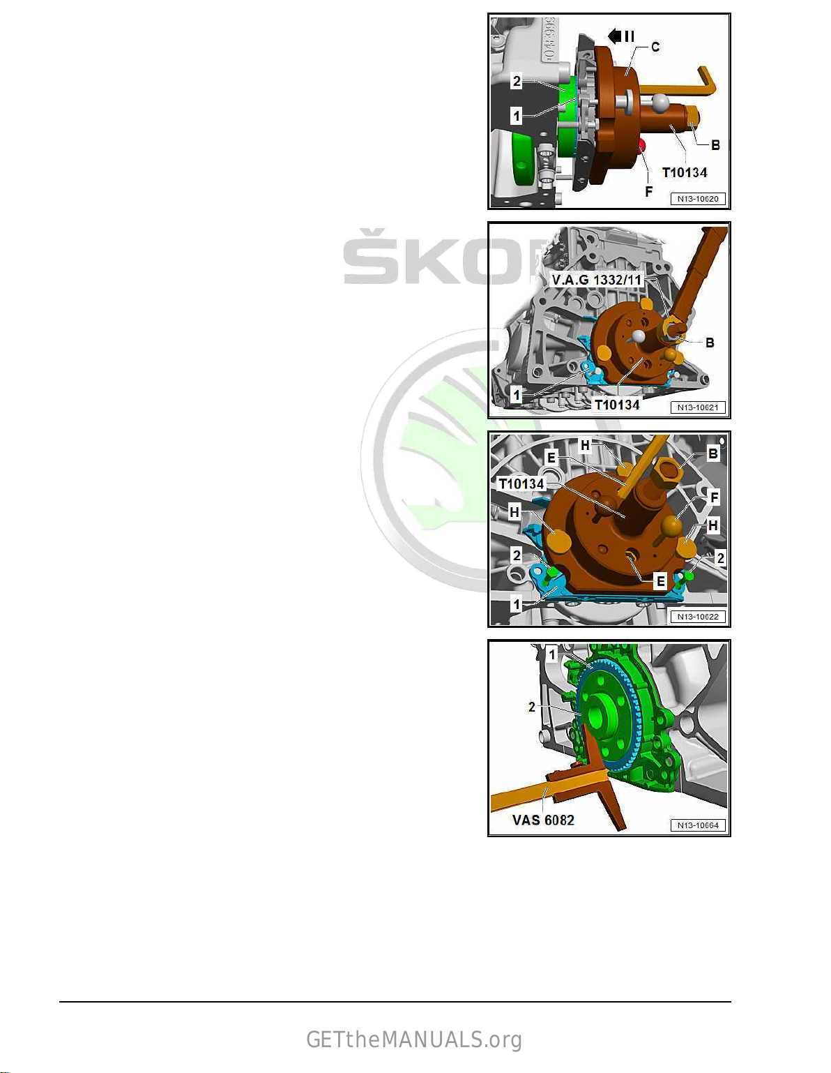
Protected by copyright. Copying for private or commercial purposes, in part or in whole, is not permitted
unless authorised by ŠKODA AUTO A. S. ŠKODA AUTO A. S. does not guarantee or accept any liability
with respect to the correctness of information in this document. Copyright by ŠKODA AUTO A. S.�
Screw C - attach assembly tool - T10134- onto crankshaft flange
GETtheMANUALS.org
– Push the assembly cup -C- by hand in the
-direction of the arrow- until the sealing lip supporting ring -1rests on the crankshaft flange -2-.
–
Push guide pin for petrol engines (red knob) -F- into hole in
crankshaft. This ensures that the sender wheel reaches its fi‐
nal installation position.
– Tighten the two hexagon socket head bolts hand-tight.
– Screw nut -B- onto threaded spindle by hand until it lies against
assembly housing -C-.
Press D - press rotor with assembly tool - T10134- onto crankshaft
flange
– Tighten nuts -B- on the assembly tool - T10134- with torque
wrench to 35 Nm.
• After tightening the nut to 35 mm there must still be a narrow
air gap between the cylinder block and the sealing flange.
E - Inspect the installation position of the rotor on the crankshaft
– Screw nut -B- on until it reaches end of threaded spindle.
– Unscrew bolts-2- from the intake manifold.
– Unscrew the knurled screws -H- from the sealing flange.
– Unscrew the Allan screws -E- from the crankshaft flange.
– Remove assembly tool - T10134- .
– Remove sealing lip support ring.
– Place caliper gauge on crankshaft flange.
60 Rep. gr.13 - Crankshaft group
Page 67
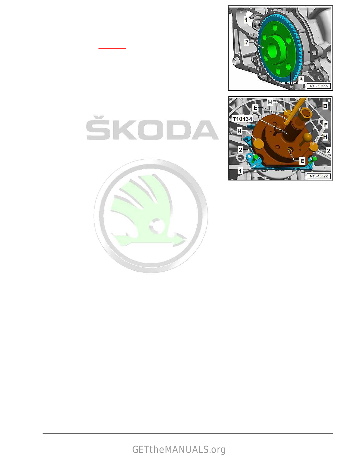
Protected by copyright. Copying for private or commercial purposes, in part or in whole, is not permitted
unless authorised by ŠKODA AUTO A. S. ŠKODA AUTO A. S. does not guarantee or accept any liability
with respect to the correctness of information in this document. Copyright by ŠKODA AUTO A. S.�
– Measure distance -a- between
GETtheMANUALS.org
crankshaft flange -2- and sen‐
sor rotor -1-.
• Specified value: Dimension -a- = 0.5 mm
If dimension »a« is too small:
– Press down rotor
⇒ page 61 .
If dimension »a« is achieved:
– Complete the remaining installation ⇒ page 62 .
F - Pressing down the rotor
– Secure assembly tool - T10134- to crankshaft flange with hex‐
agon socket head bolts -E-.
Make sure the positioning pin of the assembly device - T10134engages in the bore of the sender wheel.
– Tighten the two hexagon socket head bolts -E- hand-tight.
– Screw the knurled screws -H- into the flange -1-.
– Screw nut -B- onto threaded spindle by hand until it lies against
the assembly housing.
2. Cylinder block on gearbox side 61
Page 68

Protected by copyright. Copying for private or commercial purposes, in part or in whole, is not permitted
unless authorised by ŠKODA AUTO A. S. ŠKODA AUTO A. S. does not guarantee or accept any liability
with respect to the correctness of information in this document. Copyright by ŠKODA AUTO A. S.�
– Tighten nut -B- of the assembly tool - T10134- to 40 Nm.
GETtheMANUALS.org
– Again inspect the fitting position of the rotor on the crankshaft
⇒ page 60 .
If the dimension »a« is too small again:
– Tighten nut -B- of the assembly tool - T10134- to 45 Nm.
– Again inspect the fitting position of the rotor on the crankshaft
⇒ page 60 .
Installing
– Tighten screws for sealing flange crosswise.
– Install oil sump bottom part
⇒ “1.3 Removing and installing oil sump bottom part”,
page 199 .
– Installing intermediate plate
⇒ Fig. ““Installing intermediate plate”“ , page 53 .
– Install flywheel
⇒ “2.2 Removing and installing flywheel”, page 53 .
NOTICE
Risk of engine damage if the locating screw - T10340- would
not be removed.
To finish off the work, check to see whether the locating screw
- T10340- has been removed.
Tightening torques
♦ Sealing flange on the gearbox side
⇒ Fig. ““Sealing flange on the gearbox side - tightening torque
and tightening order”“ , page 53 .
♦ Engine speed sender - G28-
⇒ “1.1 Assembly overview - ignition system”, page 360 .
♦ Ignition coil with power output stage
⇒ “1.1 Assembly overview - ignition system”, page 360 .
♦ Spark plug
⇒ “1.1 Assembly overview - ignition system”, page 360 .
♦ Flywheel to crankshaft
⇒ “2.1 Summary of components - cylinder block on gearbox
side”, page 52 .
Component Specified torque
Screw plug for bore in the cyl‐
inder block
Locating screw - T10340- 30 Nm
30 Nm
62 Rep. gr.13 - Crankshaft group
Page 69

Protected by copyright. Copying for private or commercial purposes, in part or in whole, is not permitted
unless authorised by ŠKODA AUTO A. S. ŠKODA AUTO A. S. does not guarantee or accept any liability
with respect to the correctness of information in this document. Copyright by ŠKODA AUTO A. S.�
3 Crankshaft
GETtheMANUALS.org
⇒ “3.1 Crankshaft dimensions”, page 63
⇒ “3.2 Replace the needle bearing in the crankshaft”, page 63
⇒ “3.3 Measuring axial play of crankshaft”, page 64
3.1 Crankshaft dimensions
NOTICE
There is a risk of bearing seat deformation.
Newer loosen the screws of the main bearing cover.
♦ The crankshaft must not be removed. Merely releasing the
screws of the crankshaft bearing cover will result in deforma‐
tions of the bearing seats of the cylinder block.
♦ If the bearing cap bolts are loosened, the cylinder block must
be renewed complete with the crankshaft.
♦ Measuring the main bearing clearance is not possible with
normal workshop equipment.
Grinding dimension
Basic dimension 48,00 –0,022
3.2 Replace the
∅ conrod journal
mm
–0,042
needle bearing in the crank‐
shaft
Only for vehicles with automatic gearbox
Special tools and workshop equipment required
♦ Centering mandrel -T30029 (3176)♦ Interior extractor -Kukko 21/2♦ Countersupport -Kukko 22/1Removing
– Remove needle bearing with internal extractor -Kukko 21/2-
and countersupport -Kukko 22/1- .
Install
Fitting position of the needle bearing:
♦ The marked side of the needle bearing should be visible when
in its installed condition.
– Clean the bearing in the crankshaft.
3. Crankshaft 63
Page 70

Protected by copyright. Copying for private or commercial purposes, in part or in whole, is not permitted
unless authorised by ŠKODA AUTO A. S. ŠKODA AUTO A. S. does not guarantee or accept any liability
with respect to the correctness of information in this document. Copyright by ŠKODA AUTO A. S.�
– Drive in needle bearing with centring mandrel -T30029 (3176)-
GETtheMANUALS.org
flush with the crankshaft face.
3.3 Measuring axial play of crankshaft
NOTICE
There is a risk of bearing seat deformation.
Newer loosen the screws of the main bearing cover.
♦ The crankshaft must not be removed. Merely releasing the
screws of the crankshaft bearing cover will result in deforma‐
tions of the bearing seats of the cylinder block.
♦ If the bearing cap bolts are loosened, the cylinder block must
be renewed complete with the crankshaft.
♦ Measuring the main bearing clearance is not possible with
normal workshop equipment.
Special tools and workshop equipment required
♦ Universal dial gauge holder - MP3-447 (VW 387)♦ Dial gauge , e.g. -VAS 6079– Secure dial gauge e.g. -VAS 6079- with the universal dial
gauge bracket - MP3-447 (VW 387)- to the cylinder block, as
shown in the illustration.
– Place dial gauge against the crankshaft cheek.
– Press crankshaft against the dial gauge and set dial gauge to
“0”.
–
Press the crankshaft off the dial gauge and read the measured
value.
• Axial clearance: 0.066…0.233 mm.
64 Rep. gr.13 - Crankshaft group
Page 71

Protected by copyright. Copying for private or commercial purposes, in part or in whole, is not permitted
unless authorised by ŠKODA AUTO A. S. ŠKODA AUTO A. S. does not guarantee or accept any liability
with respect to the correctness of information in this document. Copyright by ŠKODA AUTO A. S.�
4 Pistons and conrods
GETtheMANUALS.org
⇒ “4.1 Assembly overview - piston and conrod”, page 65
⇒ “4.2 Removing and installing the piston”, page 67
⇒ “4.3 Checking piston and cylinder bore”, page 68
⇒ “4.4 Removing and installing oil injection nozzles”, page 69
4.1 Assembly overview - piston and conrod
1 - Screw
❑ Replace after disas‐
sembly
❑
Oil threads and contact
surface
❑ 30 Nm + 90°
2 - Conrod bearing cap
❑ as a result of the con‐
rods separated in the
cracking process, the
conrod bearing cap fits
only in one position and
only to the relevant con‐
rod
❑ Mark assignment to the
cylinder and to the con‐
rod in colour -B-
❑ Fitting position: Peg -A-
on the conrod bearing
cap points to the belt
pulley side
3 - Bearing shells
❑ Fitting position
⇒ Fig. ““Bearing shell in‐
stallation position”“ ,
page 66
❑ replace used bearing
shells
❑
check for firm seating
4 - Conrod
❑ with cracked conrod
bearing cap
❑ Replace as set only.
❑ Mark assignment to the
cylinder and to the conrod bearing cap in colour -B❑ separate new connecting rod
❑ Fitting position: Peg -A- on the conrod bearing cap points to the belt pulley side
5 - Circlip
❑
2 pieces
❑ Replace after disassembly
6 - Piston pin
❑ removing and installing
7 - Piston
❑ with combustion chamber
⇒ Fig. ““Separating new conrod bearing cap”“ , page 67
⇒ “4.2 Removing and installing the piston”, page 67
4. Pistons and conrods 65
Page 72

Protected by copyright. Copying for private or commercial purposes, in part or in whole, is not permitted
unless authorised by ŠKODA AUTO A. S. ŠKODA AUTO A. S. does not guarantee or accept any liability
with respect to the correctness of information in this document. Copyright by ŠKODA AUTO A. S.�
❑ Mark the installation position and the assignment to cylinder
GETtheMANUALS.org
⇒ Fig. ““Fitting position of piston and assignment of piston to cylinder”“ , page 66
❑ removing and installing ⇒ “4.2 Removing and installing the piston”, page 67
❑ Check piston and cylinder bore ⇒ “4.3 Checking piston and cylinder bore”, page 68
8 - Piston rings
❑ Compression rings
❑
Measure end gap
❑ Measure vertical gap ⇒ Fig. ““Measure piston ring vertical gap”“ , page 69
❑ use commercially available piston ring pliers for removing and installing
❑
Fitting position: Identification “TOP” or labelled side for piston crown
❑ Offset gaps by 120°
9 - Piston ring
❑ Oil scraper ring
❑ Measure end gap
❑ Measure vertical gap ⇒ Fig. ““Measure piston ring vertical gap”“ , page 69
❑ use piston ring pliers for removing and installing
❑
Fitting position: Identification “TOP” or labelled side for piston crown
❑ Offset joint 120° to bottom compression ring
Fitting position of piston and assignment of piston to cylinder
⇒ Fig. ““Measure piston ring end gap”“ , page 68
⇒ Fig. ““Measure piston ring end gap”“ , page 68
NOTICE
Risk of damaging the piston crown.
♦ For re-installation, mark the assignment in colour on the piston
crown of cylinders that have already been used. Do not mark
piston crown not using centre punch, scratch, nick or similar.
• Arrow on the piston crown to the belt pulley side -arrow-.
Bearing shell installation position
– Insert bearing shells centrally in the conrod and conrod bear‐
ing cap.
• Dimension -a- = 2.5 mm.
66 Rep. gr.13 - Crankshaft group
Page 73

Protected by copyright. Copying for private or commercial purposes, in part or in whole, is not permitted
unless authorised by ŠKODA AUTO A. S. ŠKODA AUTO A. S. does not guarantee or accept any liability
with respect to the correctness of information in this document. Copyright by ŠKODA AUTO A. S.�
Separating new conrod bearing cap
GETtheMANUALS.org
On new conrods it is possible that the breaking point is not fully
separated. If
the conrod bearing cap cannot be removed by hand,
proceed as follows:
– To prevent damage, tension the conrod only slightly in a vice
with protective jaws as shown.
• Tension the conrod below the dotted line.
– Unscrew screws -arrows- by approx. 5 turns.
– Knock against the conrod bearing cap carefully with a plastic
hammer -arrow- in order to loosen it.
4.2 Removing and installing the piston
Special tools and workshop equipment required
♦ Drift - VW 222 A-
♦ Commercially available piston ring tensioning strap
Removing
• Engine attached to engine and gearbox mount - VAS 6095-
⇒ “1.3 Attach engine attached to engine and gearbox mount”,
page 20 .
– Remove cylinder head
⇒ “1.3 Removing and installing the cylinder head”,
page 79 .
– Remove oil sump top part
⇒ “1.4 Removing and installing oil sump top part”, page 202
and remove baffle.
– Mark installation position and assignment of the piston to the
cylinder.
– Mark the installation position and assignment of the conrod to
the cylinder and to the conrod bearing cap
-Pos. 4-
⇒ “4.1 Assembly overview - piston and conrod”, page 65 .
– Remove conrod bearing cap and pull out piston with conrod
upwards.
Note
In case of tightness of the piston pin, heat piston to approximately
60 °C.
– Remove securing rings from the piston pin eye.
– Drive off piston pin with a drift - VW 222 A- .
4. Pistons and conrods 67
Page 74

Protected by copyright. Copying for private or commercial purposes, in part or in whole, is not permitted
unless authorised by ŠKODA AUTO A. S. ŠKODA AUTO A. S. does not guarantee or accept any liability
with respect to the correctness of information in this document. Copyright by ŠKODA AUTO A. S.�
Install
GETtheMANUALS.org
Installation is performed in the reverse order, pay attention to the
following points:
– Oil the contact surfaces of the bearing shells.
– Install piston with commercially available piston ring tension‐
ing strap, check installation position
⇒ Fig. ““Fitting position of piston and assignment of piston to
cylinder”“ , page 66 .
– Install conrod bearing cap, check installation position Pos.
-2- ⇒ “4.1 Assembly overview - piston and conrod”, page 65 .
– Install cylinder head
⇒ “1.3 Removing and installing the cylinder head”,
page 79 .
– Install sump top part
⇒ “1.4 Removing and installing oil sump top part”, page 202 .
Tightening torques
♦ Conrod bearing cap
⇒ “4.1 Assembly overview - piston and conrod”, page 65 .
4.3 Checking piston and cylinder bore
Checking piston
– Using an external micrometer, measure pistons approx.
10 mm from the lower edge of skirt, at 90° to the piston pin
axis.
• Maximum deviation from nominal dimension: 0.04 mm.
Piston ∅ mm
Nominal dimension
1)
•
dimensions without coating
74,42
1)
• Manufacturer of the piston Federal Mogul (thickness 0.018
mm per side)
• Manufacturer of the piston Mahle (thickness 0.015 mm per
side)
Measure piston ring end gap
– Insert ring at right angles from above down into lower cylinder
bore, about 15 mm away from edge of cylinder.
–
Push a commercially available feeler gauge into the piston ring
opening to check the end gap.
Piston ring
Sealing ring
2-part oil scraper ring
3-part oil scraper ring
New
mm
0,20
0,20
0,50
+ 0,15
+ 0,20
+ 0,20
Wear limit
mm
1,0
3,0
3,0
68 Rep. gr.13 - Crankshaft group
Page 75
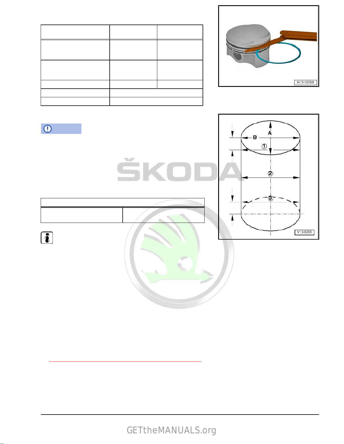
Protected by copyright. Copying for private or commercial purposes, in part or in whole, is not permitted
unless authorised by ŠKODA AUTO A. S. ŠKODA AUTO A. S. does not guarantee or accept any liability
with respect to the correctness of information in this document. Copyright by ŠKODA AUTO A. S.�
Measure piston ring vertical gap
GETtheMANUALS.org
– Clean before inspecting the annular groove of the piston.
Piston ring New
mm
1. Compressor ring (man‐
0,05 … 0,09 0,15
Wear limit
mm
ufacturer of piston rings is
Federal Mogul)
1. Compressor ring (man‐
0,035 … 0,085 0,15
ufacturer of piston rings is
Mahle)
2. Sealing ring 0,030 ...0,070 0,15
3-part oil scraper rings Not measurable
2-part oil scraper rings 0,04 ...0,08
Measure cylinder bore
NOTICE
There is risk of damaging the cylinder bore surface.
♦ Do not use normal workshop equipment to work on cylinder
bore (boring, honing, grinding).
– Using the internal precision instrument - VAS 6078- , measure
crosswise at 3 points in the transverse direction
-A- and lon‐
gitudinal direction -B-.
• Maximum deviation from nominal dimension: 0.08 mm
Cylinder bore ∅ mm
Nominal dimension
74,5 + 0,015
1)
+0,005
Note
Cylinder bores must not be measured when cylinder block is
mounted on engine and gearbox support - VAS 6095- , as meas‐
urements may be incorrect.
4.4 Removing and installing oil injection nozzles
Special tools and workshop equipment required
♦ Torx insert T40 - T10545Removing
– Remove the sound dampening system ⇒ General body re‐
pairs, exterior ; Rep. gr. 66 ; Noise insulation; Summary of
components - noise insulation .
– Remove oil sump top part
⇒ “1.4 Removing and installing oil sump top part”, page 202
and remove baffle.
4. Pistons and conrods 69
Page 76
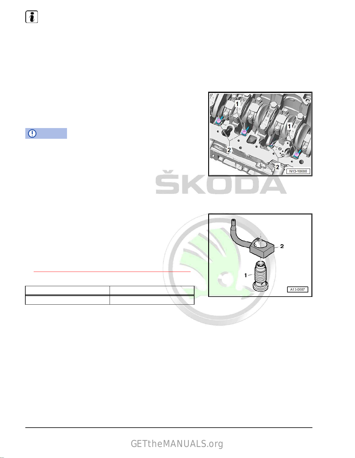
Protected by copyright. Copying for private or commercial purposes, in part or in whole, is not permitted
unless authorised by ŠKODA AUTO A. S. ŠKODA AUTO A. S. does not guarantee or accept any liability
with respect to the correctness of information in this document. Copyright by ŠKODA AUTO A. S.�
Note
GETtheMANUALS.org
♦
The crankshaft must be turned so that the Torx insert T40 T10545- can be inserted into the applicable pressure relief
valve.
♦
The teeth of Torx insert T40 - T10545- and the pressure relief
valve must engage correctly.
– Turn the crankshaft using the locating screw of the vibration
damper in direction of rotation of engine until the pressure re‐
lief valve is accessible.
– Unscrew and remove the pressure relief valves -1- with Torx
insert T40 - T10545- .
– Remove oil spray nozzles -2-.
Install
NOTICE
Risk of damaging the oil injection nozzles.
Do not bend oil injection nozzles.
♦ Replace the oil injection nozzles if they are bent.
♦ Check clearance of pistons from oil injection nozzles after re‐
installing the piston and nozzles.
Installation is performed in the reverse order, pay attention to the
following points:
Oil spray nozzle and pressure relief valve
• Fitting position: Align the guide edge of the oil injection nozzle
to the area of the cylinder block being worked on.
1 - Pressure relief valve
2 - Oil spray nozzle (for cooling piston)
– Fit baffle plate and install sump top part
⇒ “1.4 Removing and installing oil sump top part”, page 202 .
Tightening torques
Component Specified torque
Pressure relief valve 27 Nm
70 Rep. gr.13 - Crankshaft group
Page 77

Protected by copyright. Copying for private or commercial purposes, in part or in whole, is not permitted
unless authorised by ŠKODA AUTO A. S. ŠKODA AUTO A. S. does not guarantee or accept any liability
with respect to the correctness of information in this document. Copyright by ŠKODA AUTO A. S.�
15 – Cylinder head, valve gear
GETtheMANUALS.org
1 Cylinder head
⇒ “1.1 Summary of components - cylinder head”, page 71
⇒ “1.2 Summary of components - camshaft housing”, page 73
⇒ “1.3 Removing and installing the cylinder head”, page 79
⇒ “1.4 Removing and installing camshaft housing”, page 84
⇒ “1.5 Testing the compression”, page 88
⇒ “1.6 Testing the combustion chamber for tightness”,
page 89
1.1 Summary of components - cylinder head
Note
♦
Summary of components of cylinder head with engine identi‐
fication characters CZCA is shown.
♦
Positions of the components are identical for engine identifi‐
cation characters CZDA and CZEA.
1. Cylinder head 71
Page 78

Protected by copyright. Copying for private or commercial purposes, in part or in whole, is not permitted
unless authorised by ŠKODA AUTO A. S. ŠKODA AUTO A. S. does not guarantee or accept any liability
with respect to the correctness of information in this document. Copyright by ŠKODA AUTO A. S.�
1 - Cylinder head gasket
GETtheMANUALS.org
❑ Replace.
⇒ “1.3 Removing and in‐
stalling the cylinder
head”, page 79 .
❑ check fitting position:
Cylinder
ber
2 - Fitting sleeve
❑ 2 pieces
3 - Cylinder head
❑ removing and installing
⇒ “1.3 Removing and in‐
stalling the cylinder
head”, page 79
❑ check for distortion
⇒ Fig. ““Inspecting the
cylinder head for distor‐
tion”“ , page 73
❑ After replacing, fill with
fresh coolant
⇒ “1.3 Draining and fill‐
ing up coolant”,
page 225
4 - Dowel pins
5 - Gasket
❑ No longer used and is
integrated
control valve 1 - N205-
and exhaust camshaft
control valve 1 - N318- .
6 - Gasket
❑ Replace after disas‐
sembly
7 - Camshaft housing
❑ The camshafts cannot be removed individually
❑ removing and installing
8 - Screw
❑ Replace after disassembly
❑
Tightening torque and tightening order
⇒ Fig. ““Camshaft housing - tightening torque and tightening order”“ , page 75
9 - Screw
❑ Replace after disassembly
❑
Loosening order
❑ Tightening torque and tightening order
⇒ Fig. ““Cylinder head - tightening torque and tightening order”“ , page 73
head part num‐
into camshaft
⇒ “1.4 Removing and installing camshaft housing”, page 84
⇒ page 83
72 Rep. gr.15 - Cylinder head, valve gear
Page 79
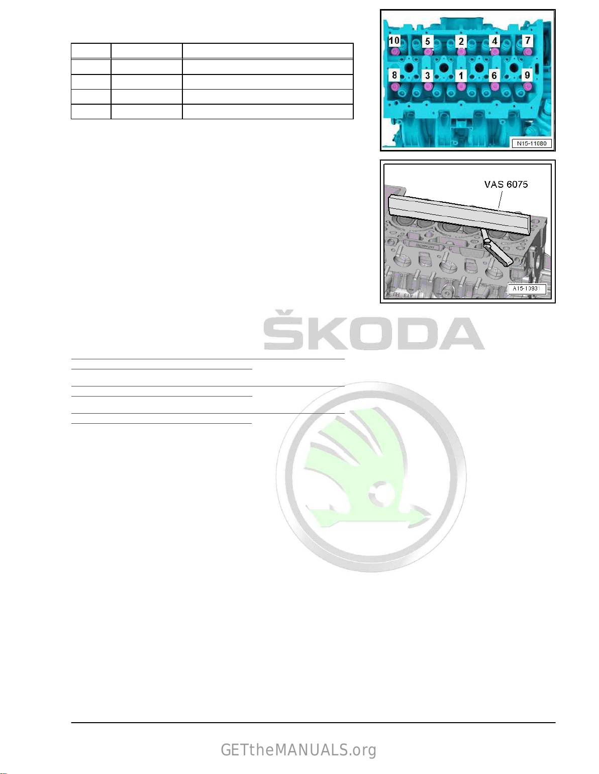
Protected by copyright. Copying for private or commercial purposes, in part or in whole, is not permitted
unless authorised by ŠKODA AUTO A. S. ŠKODA AUTO A. S. does not guarantee or accept any liability
with respect to the correctness of information in this document. Copyright by ŠKODA AUTO A. S.�
Cylinder head - tightening torque and tightening order
GETtheMANUALS.org
– Tighten screws in steps in the given sequence:
Stage Screws Tightening torque/torquing angle
1. -1 … 10- 40 Nm
2. -1 … 10- Turn 90° further
3. -1 … 10- Turn 90° further
4. -1 … 10- Turn 90° further
Inspecting the cylinder head for distortion
– Inspect cylinder head at several points for distortion using a
500 mm knife-edge straightedge - VAS 6075- and feeler
gauge.
• Maximum permitted distortion: 0.05 mm.
1.2 Summary of components - camshaft housing
⇒ “1.2.1 Summary of components - camshaft housing, engine
identification characters CZCA”, page 73
⇒ “1.2.2 Summary of components - camshaft housing, engine
identification characters CZDA”, page 76
⇒ “1.2.3 Summary of components - camshaft housing, engine
identification characters CZEA”, page 78
1.2.1 Summary of
components - camshaft housing, engine identification charac‐
ters CZCA
1. Cylinder head 73
Page 80

Protected by copyright. Copying for private or commercial purposes, in part or in whole, is not permitted
unless authorised by ŠKODA AUTO A. S. ŠKODA AUTO A. S. does not guarantee or accept any liability
with respect to the correctness of information in this document. Copyright by ŠKODA AUTO A. S.�
1 - Screw
GETtheMANUALS.org
❑ Replace after disas‐
sembly
❑
Tightening torque and
tightening order
⇒ Fig. ““Camshaft hous‐
ing - tightening torque
and tightening order”“ ,
page 75
2 -
Inlet camshaft control valve
1 - N205-
❑ removing and installing
⇒ “3.6 Removing and
installing N205 the cam‐
shaft adjustment valve
1”, page 188
3 - Screw
❑ 8 Nm
4 - Camshaft housing
❑
The camshafts cannot
be removed individually
❑ removing and installing
⇒ “1.4 Removing and in‐
stalling camshaft hous‐
ing”, page 84
5 - Hall sender - G40-
❑ removing and installing
⇒ “1.4.1 Removing and
installing Hall sender
G40 ”, page 364
6 - Screw
❑ 8 Nm
7 - Sealing ring
❑
for exhaust camshaft on
the gearbox side
❑ removing and installing
⇒ “3.3.3 Removing and installing exhaust camshaft on gearbox side, engine identification characters
CZCA, CZDA”, page 179
8 - Toothed belt pulley
❑ For coolant pump
❑
removing and installing
⇒ “2.7 Removing and installing toothed belt pulley for coolant pump”, page 242
9 - Screw
❑ Replace after disassembly
❑
20 Nm + 90°
10 - Screw
❑ 8 Nm
11 - Screw cap
12 - O-ring
❑ Replace after disassembly
13 - Gasket
❑ Replace after disassembly
❑ Different versions ⇒ ETKA - Electronic Catalogue of Original Parts
74 Rep. gr.15 - Cylinder head, valve gear
Page 81

Protected by copyright. Copying for private or commercial purposes, in part or in whole, is not permitted
unless authorised by ŠKODA AUTO A. S. ŠKODA AUTO A. S. does not guarantee or accept any liability
with respect to the correctness of information in this document. Copyright by ŠKODA AUTO A. S.�
14 - Fit pin
GETtheMANUALS.org
15 - Gasket
❑ No longer present and is integrated into valve 1 for camshaft control - N205- item -2-
16 - Sealing ring
❑
For inlet camshaft.
❑ replace after removal
⇒ “3.3.1 Removing and installing the inlet camshaft on the belt pulley side”, page 176
17 - Sealing ring
❑ for exhaust camshaft on the belt pulley side
❑
replace after removal
⇒ “3.3.2 Removing and installing the exhaust camshaft on the belt pulley side”, page 177
❑
18 - Screw cap
Camshaft housing - tightening torque and tightening order
– Tighten screws gradually in the given sequence:
Stage Screws Tightening torque/torqueing angle
1. -1…15- 10 Nm
2. -1…15- Turn 180° further
1. Cylinder head 75
Page 82

Protected by copyright. Copying for private or commercial purposes, in part or in whole, is not permitted
unless authorised by ŠKODA AUTO A. S. ŠKODA AUTO A. S. does not guarantee or accept any liability
with respect to the correctness of information in this document. Copyright by ŠKODA AUTO A. S.�
1.2.2 Summary of components - camshaft housing, engine identification charac‐
GETtheMANUALS.org
ters CZDA
1 - Camshaft control valve 1 in
the exhaust - N318-
❑ removing and installing
⇒ “3.7 Removing and
installing camshaft con‐
trol valve 1 in the ex‐
haust N318 ”,
page 188
2 - Screw
❑ 8 Nm
3
- Inlet camshaft control valve
1 - N205-
❑ removing and installing
⇒ “3.6 Removing and
installing N205 the cam‐
shaft adjustment valve
1”, page 188
4 - Camshaft housing
❑ The camshafts cannot
be removed individually
❑
removing and installing
⇒ “1.4 Removing and in‐
stalling camshaft hous‐
ing”, page 84
5 - Hall sender 3 - G300-
❑ removing and installing
⇒ “1.4.2 Removing and
installing hall sender 3
G300 ”, page 364
6 - Screw
❑ 8 Nm
7 - Hall transmitter - G40-
❑
removing and installing
⇒ “1.4.1 Removing and
installing Hall sender G40 ”, page 364
8 - Sealing ring
❑ for exhaust camshaft on the gearbox side
❑
removing and installing
⇒ “3.3.3 Removing and installing exhaust camshaft on gearbox side, engine identification characters
CZCA, CZDA”, page 179
9 - Toothed belt pulley
❑ For coolant pump
❑
removing and installing
⇒ “2.7 Removing and installing toothed belt pulley for coolant pump”, page 242
10 - Screw
❑ Replace after disassembly
❑
20 Nm + 90°
11 - Screw
❑ 8 Nm
76 Rep. gr.15 - Cylinder head, valve gear
Page 83

Protected by copyright. Copying for private or commercial purposes, in part or in whole, is not permitted
unless authorised by ŠKODA AUTO A. S. ŠKODA AUTO A. S. does not guarantee or accept any liability
with respect to the correctness of information in this document. Copyright by ŠKODA AUTO A. S.�
12 - Screw cap
GETtheMANUALS.org
13 - O-ring
❑ Replace after disassembly
14 - Gasket
❑
Replace after disassembly
❑ Different versions ⇒ ETKA - Electronic Catalogue of Original Parts
15 - Fit pin
16 - Gasket
❑ No longer used and is integrated into camshaft control valve 1 - N205- Pos. -3- and exhaust camshaft
control valve 1 - N318- Pos. -1-.
17 - Sealing ring
❑ For inlet camshaft.
❑ replace after removal
⇒ “3.3.1 Removing and installing the inlet camshaft on the belt pulley side”, page 176
18 - Sealing ring
❑ for exhaust camshaft on the belt pulley side
❑
replace after removal
⇒ “3.3.2 Removing and installing the exhaust camshaft on the belt pulley side”, page 177
❑
19 - Screw cap
20 - Screw
❑ Replace after disassembly
❑
Tightening torque and tightening order
⇒ page 77
Camshaft housing - tightening torque and tightening order
– Tighten screws gradually in the given sequence:
Stage Screws Tightening torque/torqueing angle
1. -1…15- 10 Nm
2. -1…15- Turn 180° further
1. Cylinder head 77
Page 84
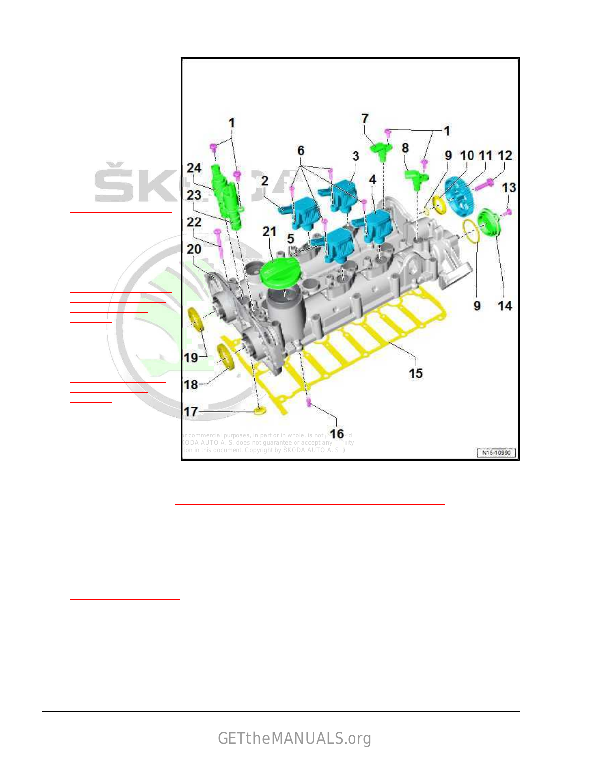
Protected by copyright. Copying for private or commercial purposes, in part or in whole, is not permitted
unless authorised by ŠKODA AUTO A. S. ŠKODA AUTO A. S. does not guarantee or accept any liability
with respect to the correctness of information in this document. Copyright by ŠKODA AUTO A. S.�
1.2.3 Summary of components - camshaft housing, engine identification charac‐
GETtheMANUALS.org
ters CZEA
1 - Screw
❑ 8 Nm
2 - Exhaust cam adjuster for
cylinder 2 - N587-
❑
removing and installing
⇒ “3.5.3 Removing and
installing exhaust cam
for cylinder 2 N587 ”,
page 185
3 - Exhaust cam adjuster for
cylinder 3 - N595-
❑ removing and installing
⇒ “3.5.4 Removing and
installing exhaust cam
for cylinder 3 N595 ”,
page 186
4 - Inlet cam adjuster for cylin‐
der 3 - N591-
❑ removing and installing
⇒ “3.5.2 Removing and
installing inlet cam for
cylinder 3 N591 ”,
page 184
5 - Inlet cam adjuster for cylin‐
der 2 - N583-
❑ removing and installing
⇒ “3.5.1 Removing and
installing inlet cam for
cylinder 2 N583 ”,
page 183
6 - Screw
❑ 8 Nm
7 - Hall sender 3 - G300-
❑
removing and installing
⇒ “1.4.2 Removing and installing hall sender 3 G300 ”, page 364
8 - Hall transmitter - G40-
❑ removing and installing ⇒ “1.4.1 Removing and installing Hall sender G40 ”, page 364
9 - O-ring
❑ Replace after disassembly
10 - Sealing ring
❑
for exhaust camshaft on the gearbox side
❑ removing and installing
⇒ “3.3.3 Removing and installing exhaust camshaft on gearbox side, engine identification characters
CZCA, CZDA”, page 179
11 - Toothed belt pulley
❑ For coolant pump
❑
removing and installing
⇒ “2.7 Removing and installing toothed belt pulley for coolant pump”, page 242
12 - Screw
❑ Replace after disassembly
❑
20 Nm + 90°
78 Rep. gr.15 - Cylinder head, valve gear
Page 85
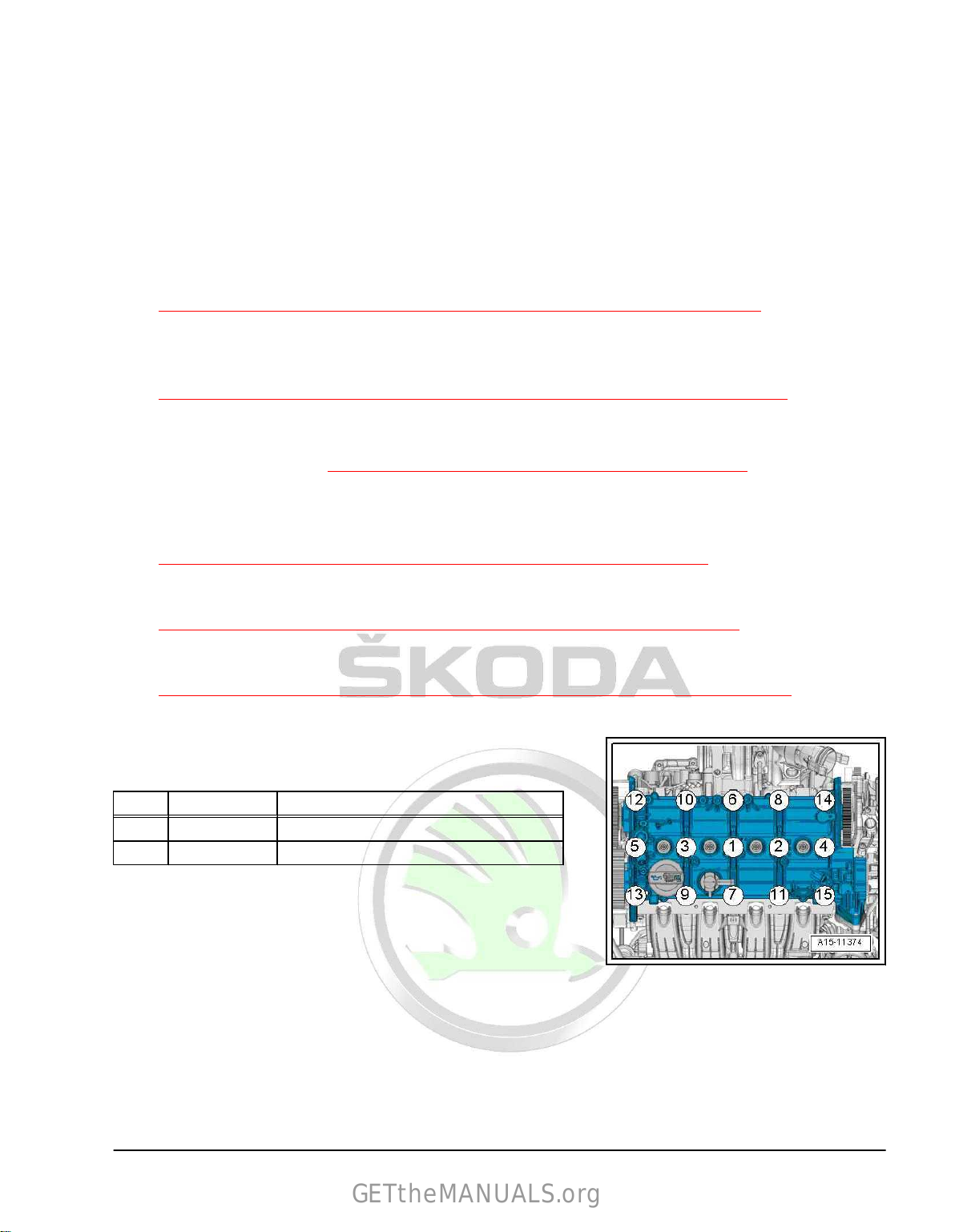
Protected by copyright. Copying for private or commercial purposes, in part or in whole, is not permitted
unless authorised by ŠKODA AUTO A. S. ŠKODA AUTO A. S. does not guarantee or accept any liability
with respect to the correctness of information in this document. Copyright by ŠKODA AUTO A. S.�
13 - Screw
GETtheMANUALS.org
❑ 8 Nm
14 - Screw cap
15 - Gasket
❑
Replace after disassembly
16 - Fit pin
17 - Gasket
❑ No longer used and is integrated into camshaft control valve 1 - N205- Pos. -23- and exhaust camshaft
control valve 1 - N318- Pos. -24-.
18 - Sealing ring
❑ For inlet camshaft.
❑ replace after removal
⇒ “3.3.1 Removing and installing the inlet camshaft on the belt pulley side”, page 176
19 - Sealing ring
❑ For exhaust camshaft.
❑
replace after removal
⇒ “3.3.2 Removing and installing the exhaust camshaft on the belt pulley side”, page 177
20 - Camshaft housing
❑ The camshafts cannot be removed individually
❑
removing and installing
⇒ “1.4 Removing and installing camshaft housing”, page 84
21 - Screw cap
22 - Screw
❑ Tightening torque and tightening order
⇒ Fig. ““Camshaft housing - tightening torque and tightening order”“ , page 79
23 - Inlet camshaft control valve 1 - N205-
❑ removing and installing
⇒ “3.6 Removing and installing N205 the camshaft adjustment valve 1”, page 188
24 - Camshaft control valve 1 in the exhaust - N318-
❑ removing and installing
⇒ “3.7 Removing and installing camshaft control valve 1 in the exhaust N318 ”, page 188
Camshaft housing - tightening torque and tightening order
– Tighten screws gradually in the given sequence:
Stage Screws Tightening torque/torqueing angle
1. -1…15- 10 Nm
2. -1…15- Turn 180° further
1.3 Removing and installing the cylinder
head
Special tools and workshop equipment required
♦ Sealant remover gasket stripper (bearing code GST, bearing
article no. R 34402), manufacturer Retech s.r.o.
♦ Cleaning and degreasing agent , e.g. -D 009 401 04-
1. Cylinder head 79
Page 86
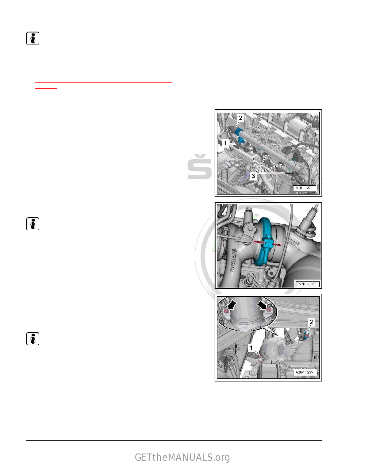
Protected by copyright. Copying for private or commercial purposes, in part or in whole, is not permitted
unless authorised by ŠKODA AUTO A. S. ŠKODA AUTO A. S. does not guarantee or accept any liability
with respect to the correctness of information in this document. Copyright by ŠKODA AUTO A. S.�
♦ Protective goggles and gloves
GETtheMANUALS.org
Removing
Note
All heat protection sleeves should be fastened again in the same
place when installing.
– Remove camshaft housing
⇒ “1.4 Removing and installing camshaft housing”,
page 84 .
– Removing the intake manifold
⇒ “4.2 Removing and installing intake manifold”, page 305 .
– Disconnect the plug connections:
1 - On the oil pressure switch for reduced oil pressure - F3782 - On the fuel pressure sender - G2473 - On injectors -N30- to -N33-
– Mark the position of the clamp.
Note
♦
Before loosening the separation point between catalytic con‐
verter and turbocharger, mark the position of the clamp.
♦
Put the clamp back into position when assembling!
– Unscrew screw -2- and remove screw clamp.
– Remove screw -1-, remove nuts -arrows- and strap up cata‐
lytic converter to the bodyshell so as not to damage the
decoupling element.
Note
do not twist decoupling element in the exhaust pipe more than
10° - risk of damage
80 Rep. gr.15 - Cylinder head, valve gear
Page 87

Protected by copyright. Copying for private or commercial purposes, in part or in whole, is not permitted
unless authorised by ŠKODA AUTO A. S. ŠKODA AUTO A. S. does not guarantee or accept any liability
with respect to the correctness of information in this document. Copyright by ŠKODA AUTO A. S.�
– Release screws -1- and remove heat shield for right cardan
GETtheMANUALS.org
shaft, if present.
– Remove heat protection sleeve for oil pressure switch - F1- .
– Disconnect electrical plug connection -arrow- at the oil pres‐
sure switch - F1- .
– Screw out the screws -arrows-, remove oil feed line -1- and oil
return pipe -2-.
– Disconnect the plug connections:
1 - Coolant temperature sender - G622 - For charge pressure regulator - V465-
1. Cylinder head 81
Page 88

Protected by copyright. Copying for private or commercial purposes, in part or in whole, is not permitted
unless authorised by ŠKODA AUTO A. S. ŠKODA AUTO A. S. does not guarantee or accept any liability
with respect to the correctness of information in this document. Copyright by ŠKODA AUTO A. S.�
– Unscrew screw -1- at the engine support.
GETtheMANUALS.org
82 Rep. gr.15 - Cylinder head, valve gear
Page 89

Protected by copyright. Copying for private or commercial purposes, in part or in whole, is not permitted
unless authorised by ŠKODA AUTO A. S. ŠKODA AUTO A. S. does not guarantee or accept any liability
with respect to the correctness of information in this document. Copyright by ŠKODA AUTO A. S.�
– Loosen and unscrew the screws for the cylinder head in the
GETtheMANUALS.org
sequence -1...10-.
– Remove cylinder head and place it on a clean base (foam).
Install
NOTICE
Risk of damaging sealing surfaces.
– Carefully remove residual sealant from the cylinder head and
cylinder block.
– Make sure this does not cause any extended scoring or
scratching.
NOTICE
Risk of damaging the cylinder block.
♦ There must be no oil or coolant in the blind holes for the cyl‐
inder head bolts in the cylinder block.
NOTICE
Risk of damage to the cylinder head gasket.
♦ Remove the new cylinder head gasket from its wrapping im‐
mediately before fitting.
♦ To prevent the silicon layer and the area of the bead from being
damaged, handle the gasket with the utmost care.
Note
♦
Replace self-locking nuts, gasket rings, gaskets and O-rings.
♦
If a replacement cylinder head must be installed, the contact
surfaces between hydraulic balancing elements, roller rocker
fingers and camshaft slideways must be oiled before the cam‐
shaft housing is installed.
♦
Secure all hose connections with hose clamps which comply
with the series design ⇒ Electronic Catalogue of Original
Parts“ETKA.” .
♦
When the cylinder head or the cylinder head gasket is re‐
placed, the engine oil must be replaced.
– Stuff clean cloth into the cylinders to avoid any dirt getting in
between cylinder wall and piston.
CAUTION
Risk of injury to eyes and skin.
Wear safety gloves and safety goggles.
– Carefully remove old sealant residue from the cylinder head
and cylinder block using a chemical sealant remover.
– Make sure that, when cleaning the cylinder head and cylinder
no foreign bodies can get into the cylinder or into the oil
block,
and coolant galleries.
1. Cylinder head 83
Page 90
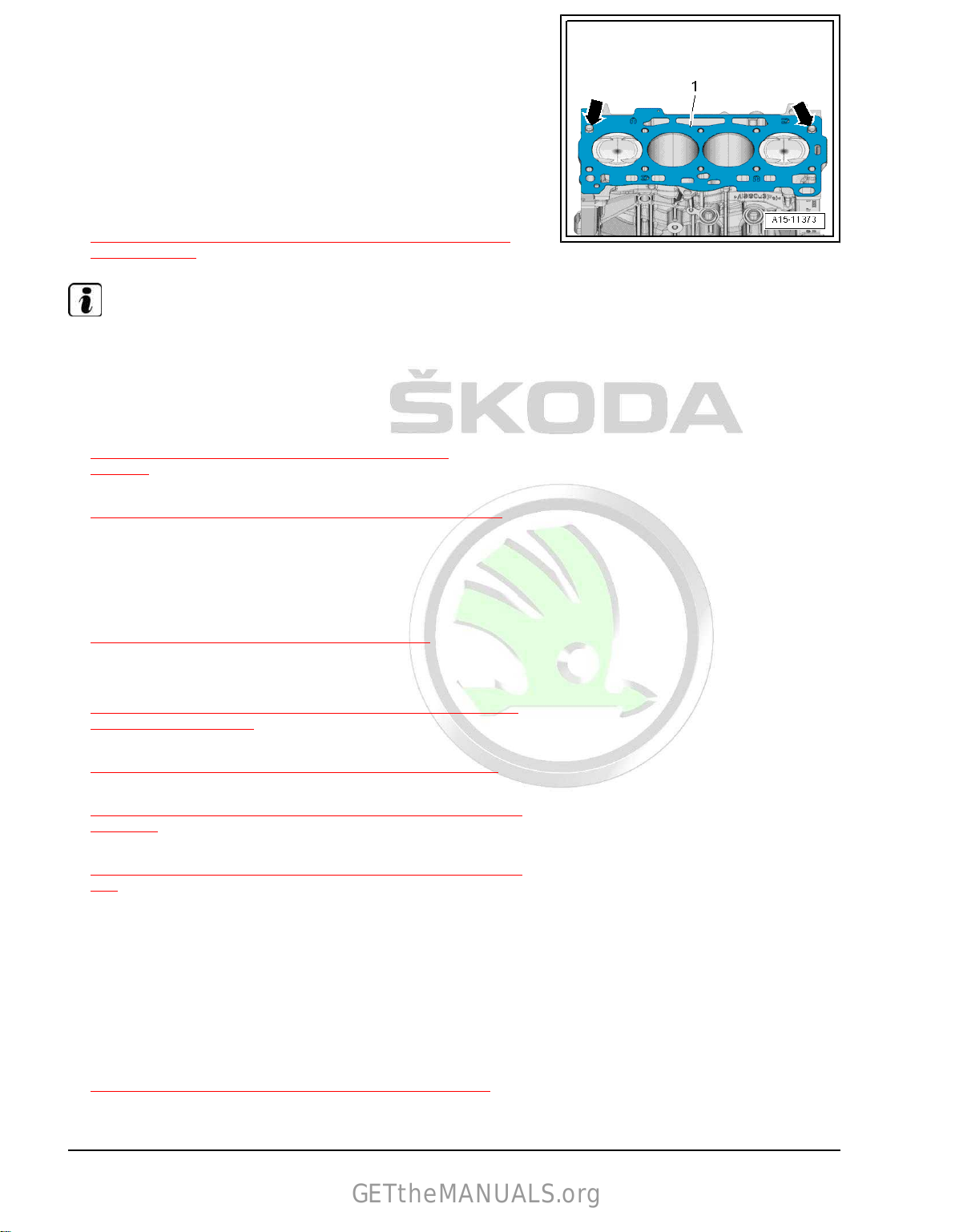
Protected by copyright. Copying for private or commercial purposes, in part or in whole, is not permitted
unless authorised by ŠKODA AUTO A. S. ŠKODA AUTO A. S. does not guarantee or accept any liability
with respect to the correctness of information in this document. Copyright by ŠKODA AUTO A. S.�
– Fit on cylinder head gasket -1-.
GETtheMANUALS.org
♦ Pay attention to dowel sleeves in cylinder block -arrows-.
♦ Check installation position of the cylinder head gasket, identi‐
fication: Part number must be legible from the inlet side.
– If the crankshaft has rotated in the meantime: Position piston
of cylinder
– Insert the cylinder head.
– Insert cylinder head bolts and tighten hand-tight.
– Tighten cylinder head bolts
⇒ Fig. ““Cylinder head - tightening torque and tightening or‐
der”“ , page 73 .
Note
1 at TDC. Turn the crank shaft back again slightly.
Tightening up the cylinder head bolts after doing repair work is
not necessary.
Installation is carried out in the reverse order. When installing,
note the following:
– Install camshaft housing
⇒ “1.4 Removing and installing camshaft housing”,
page 84 .
– Installing the intake manifold
⇒ “4.2 Removing and installing intake manifold”, page 305 .
– Change engine oil:
♦ ⇒ Maintenance ; Booklet Superb III
♦ ⇒ Maintenance ; Booklet Kodiaq
– Replace coolant
⇒ “1.3 Draining and filling up coolant”, page 225 .
Tightening torques
♦ Engine support bracket
⇒ Fig. ““Engine support bracket - tightening torque and tight‐
ening order”“ , page 27 .
♦ Cylinder head
⇒ “1.1 Summary of components - cylinder head”, page 71 .
♦ Oil line for exhaust gas turbocharger
⇒ “1.1 Summary of components - exhaust gas turbocharger”,
page 268 .
♦ Install high catalytic converter
⇒ “2.1 Summary of components - exhaust gas cleaning”, page
348 .
♦ Heat shield for cardan shaft ⇒ Chassis, axles, steering; Rep.
gr. 40 ; Cardan shaft; installing and removing heat shield for
cardan shaft .
1.4 Removing and
ing
Removing
– Remove coolant pump
⇒ “2.5 Removing and installing coolant pump”, page 235 .
84 Rep. gr.15 - Cylinder head, valve gear
installing camshaft hous‐
Page 91

Protected by copyright. Copying for private or commercial purposes, in part or in whole, is not permitted
unless authorised by ŠKODA AUTO A. S. ŠKODA AUTO A. S. does not guarantee or accept any liability
with respect to the correctness of information in this document. Copyright by ŠKODA AUTO A. S.�
– Remove air filter housing
GETtheMANUALS.org
⇒ “3.2 Removing and installing air filter housing”, page 302 .
– Removing ignition coils
⇒ “1.2 Removing and installing ignition coils with output stage”,
page 361 .
– Remove the toothed belt from the camshafts
⇒ “2.5 Remove the toothed belt from the camshaft”,
page 140 .
– Remove high pressure pipe -3-
⇒ “7.3 Removing and installing high pressure pipe”,
page 321 .
– Separate electrical plug connection -1-.
– Loosen hose clamp -2- and disconnect hose.
– Separate electrical plug connection -2-.
– Release screws -arrows- and remove connection piece -1-.
– Loosen hose clamp -2- and remove coolant hose.
– Unscrew -arrows- screws and swivel coolant lines -1- to the
right side.
– Release screws -arrows- and remove mount with heat shield
-1-.
1. Cylinder head 85
Page 92

Protected by copyright. Copying for private or commercial purposes, in part or in whole, is not permitted
unless authorised by ŠKODA AUTO A. S. ŠKODA AUTO A. S. does not guarantee or accept any liability
with respect to the correctness of information in this document. Copyright by ŠKODA AUTO A. S.�
– Remove connector -arrow- from manifold pressure sender -
GETtheMANUALS.org
GX9- .
– Disconnect the plug connections:
1 - for cam adjuster - N583- / -N587- / -N591- / -N595- (only for
engine identification characters CZEA)
2 - for Hall sender - G40- and Hall sender 3 - G300- (only for
engine identification characters CZEA, CZDA)
4 - for camshaft control valve 1 - N205- and camshaft control valve
1 in the exhaust - N318- (only for engine identification characters
CZDA, CZEA).
– Unscrew screw -3- and expose the wiring loom and lay it to
the left-hand side.
– Pull out oil dipstick -5-.
– Loosen and unscrew screws for camshaft housing in the se‐
quence -15- to -1-.
– Carefully unscrew the camshaft housing and remove from the
bonding.
– When installing again, mark the assignment of the roller rocker
finger and the balancing elements.
– Remove the roller rocker finger together with the balancing
elements and lay aside on a clean surface.
Install
Note
Replace gasket.
– “Check TDC” position of camshaft and crankshaft:
NOTICE
Risk of damaging the valve gear.
♦ When turning, the camshafts must not be moved axially.
86 Rep. gr.15 - Cylinder head, valve gear
Page 93

Protected by copyright. Copying for private or commercial purposes, in part or in whole, is not permitted
unless authorised by ŠKODA AUTO A. S. ŠKODA AUTO A. S. does not guarantee or accept any liability
with respect to the correctness of information in this document. Copyright by ŠKODA AUTO A. S.�
Engine identification characters CZEA
GETtheMANUALS.org
• Camshaft clamp - T10504- attached to camshaft housing.
Engine identification characters CZCA, CZDA
• Camshaft clamp - T10494- attached to camshaft housing.
Continued for all engine identification character
• Fixing screw - T10340- turned up to the stop in the cylinder
block and tightened to 30 Nm.
• Crankshaft in engine direction of rotation applied to the locat‐
ing screw - T10340- = “TDC” position.
– Check that all roller rocker fingers are lying flat correctly on the
end of the valve stem and are clipped into the respective bal‐
ancing element.
– Fit gasket onto dowel pins -arrows-.
1. Cylinder head 87
Page 94
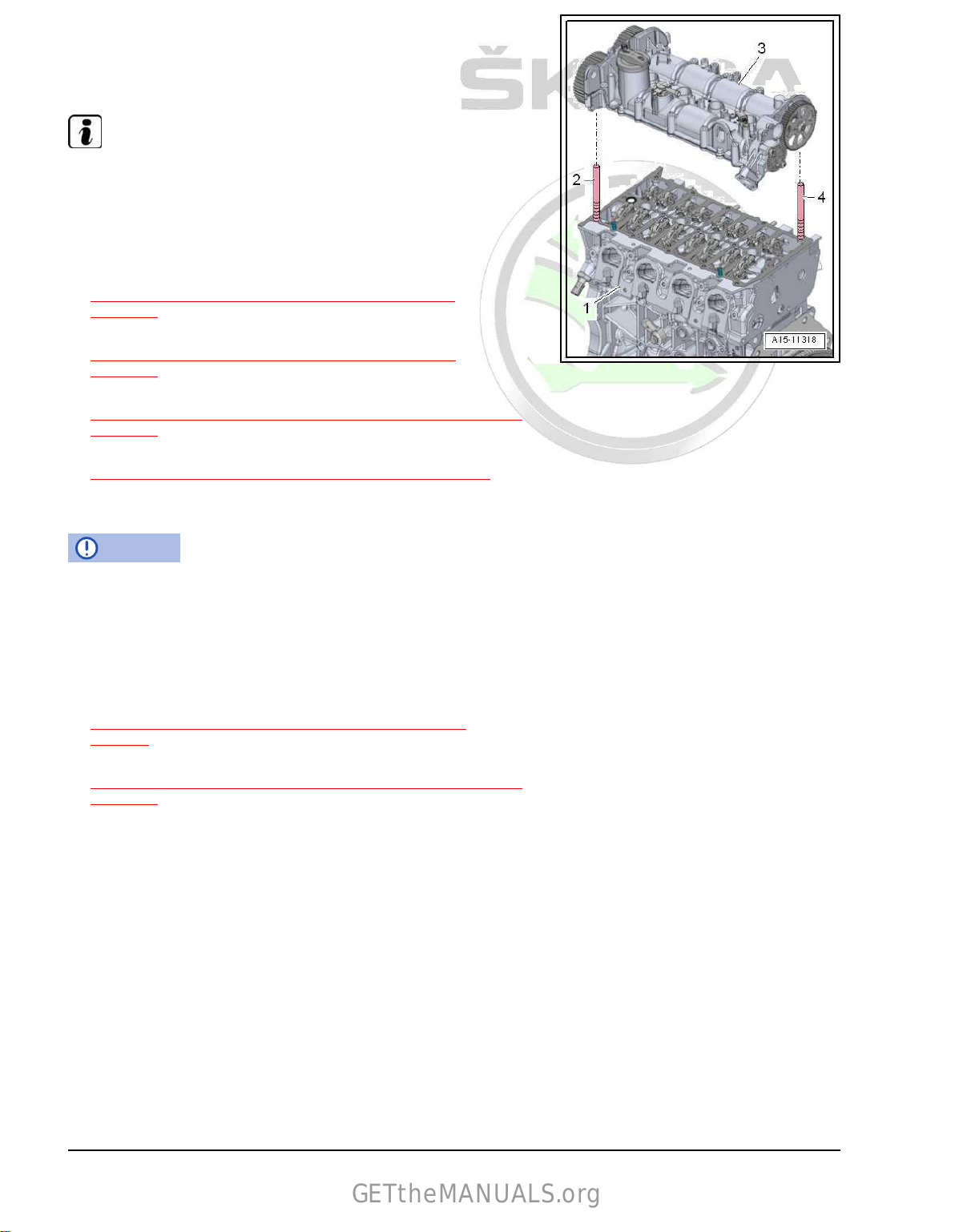
Protected by copyright. Copying for private or commercial purposes, in part or in whole, is not permitted
unless authorised by ŠKODA AUTO A. S. ŠKODA AUTO A. S. does not guarantee or accept any liability
with respect to the correctness of information in this document. Copyright by ŠKODA AUTO A. S.�
– Screw in threaded bolts -2- and -4-, e.g. -T10288/4- , into the
GETtheMANUALS.org
cylinder head.
– Carefully place
to the threaded bolts in the cylinder head.
Note
camshaft housing -3- vertically from above on‐
Make sure that the camshaft housing does not tilt.
– Tighten camshaft housing screws.
Installation is carried out in the reverse order. When installing,
note the following:
– Install high pressure pipe
⇒ “7.3 Removing and installing high pressure pipe”,
page 321 .
– install (set the timing)
⇒ “2.5 Remove the toothed belt from the camshaft”,
page 140 .
– Install ignition coils
⇒ “1.2 Removing and installing ignition coils with output stage”,
page 361 .
– Install coolant pump
⇒ “2.5 Removing and installing coolant pump”, page 235 .
– Electrical connections and proper routing ⇒ Current flow dia‐
grams, Electrical fault finding and Fitting locations.
NOTICE
Risk of damaging valves and piston crowns after work on the
valve gear.
To ensure that no valve is set during starting, turn the engine
carefully by at least 2 turns.
Tightening torques
♦ Camshaft housing
⇒ “1.2 Summary of components - camshaft housing”,
page 73 .
♦ Exhaust gas turbocharger
⇒ “1.1 Summary of components - exhaust gas turbocharger”,
page 268 .
1.5 Testing the compression
Special tools and workshop equipment required
♦ Spark plug wrench , e.g. -3122 B♦ Compression tester - V.A.G 1763-
• Engine oil temperature at least 30 °C.
• Battery voltage at least 12.5 V.
– Remove fuse for fuel pump control unit from the fuse holder.
Fuse assignment ⇒ Current flow diagrams, Electrical fault
finding and Fitting locations
88 Rep. gr.15 - Cylinder head, valve gear
Page 95

Protected by copyright. Copying for private or commercial purposes, in part or in whole, is not permitted
unless authorised by ŠKODA AUTO A. S. ŠKODA AUTO A. S. does not guarantee or accept any liability
with respect to the correctness of information in this document. Copyright by ŠKODA AUTO A. S.�
Note
GETtheMANUALS.org
Removing fuse interrupts the voltage supply of the fuel pump
control unit.
– Start engine and allow to run until it has cut out.
– Switch off ignition.
– Pull out ignition coils at power output stage
⇒ “1.2 Removing and installing ignition coils with output stage”,
page 361 .
– Unscrew spark
plugs with spark plug wrench , e. g. -3122 B- .
– Check the compression pressure using the compression test‐
er - V.A.G 1763- ; handling, ⇒ Operating Manual .
– 2nd mechanic depresses the accelerator pedal fully and at the
same time actuates the starter until the tester shows no further
pressure rise.
– Repeat the work procedure for each cylinder.
Compression readings
New part
1,0 ... 1.5 MPa
(10.0…15.0 bar)
Wear limit 0.7 MPa (7.0
bar)
Maximum difference between cylinders 0.3 MPa (3.0
bar)
Install
Installation is performed in the reverse order, pay attention to the
following points:
– Install spark plugs.
– Install ignition coils at power output stage
⇒ “1.2 Removing and installing ignition coils with output stage”,
page 361 .
Because the electrical plug connections were disconnected and
the engine started, faults are stored in the event memory of the
engine control unit.
– Clear event memory and re-generate the readiness
code ⇒ Vehicle diagnostic tester.
Tightening torques
♦ Ignition coil with power output stage
⇒ “1.1 Assembly overview - ignition system”, page 360 .
♦ Spark plugs
⇒ “1.1 Assembly overview - ignition system”, page 360 .
1.6 Testing the combustion chamber for
tightness
Special tools and workshop equipment required
♦ Spark plug wrench , e.g. -3122 B♦ Adapter - T40012- or -VAS 5161A/35– Remove ignition coils with power output stage
⇒ “1.2 Removing and installing ignition coils with output stage”,
page 361 .
1. Cylinder head 89
Page 96

Protected by copyright. Copying for private or commercial purposes, in part or in whole, is not permitted
unless authorised by ŠKODA AUTO A. S. ŠKODA AUTO A. S. does not guarantee or accept any liability
with respect to the correctness of information in this document. Copyright by ŠKODA AUTO A. S.�
– Unscrew the spark plugs with spark plug wrench - 3122 B- .
GETtheMANUALS.org
– Carefully insert a screwdriver into the opening of the ignition
plug of the appropriate cylinder, minimum length of shaft 250
mm, in -direction of arrow- so that it touches the piston head.
– Turn the crankshaft until the piston is at “TDC”.
– Screw the pressure hose MP 1-210 into the spark plug thread.
–
Connect pressure hose to compressed air supply.
– With the assistance of a second mechanic, lock the screw on
the crankshaft at “TDC” position in order to avoid displacement
of the piston after pressure build-up.
♦ Vehicles without air conditioning system Pos. -1-
⇒ “1.1.1 Summary of components - Vehicles without air con‐
ditioning”, page 36 .
♦ Vehicles with air conditioning Pos. -2-
⇒ “1.1.2 Summary of components - Vehicles with air condi‐
tioning”, page 38 .
Note
Perform a pressure build-up in the “TDC” position when the in‐
duction and outlet valves are closed.
– Build up a pressure of 0.3 MPa (3 bar) in the combustion
chamber.
– Repeat the test for the remaining cylinder.
– Determine how the pressure escapes:
1 - Via the inlet valve(s) - the pressure enters the throttle valve.
2 - Via the outlet valve(s) - the pressure enters the exhaust
system.
3 - Via the piston rings - the pressure enters the cylinder block.
Tightening torques
♦ Spark plugs
⇒ “1.1 Assembly overview - ignition system”, page 360 .
♦ Screw for ignition coil with power output stage
⇒ “1.1 Assembly overview - ignition system”, page 360 .
90 Rep. gr.15 - Cylinder head, valve gear
Page 97

Protected by copyright. Copying for private or commercial purposes, in part or in whole, is not permitted
unless authorised by ŠKODA AUTO A. S. ŠKODA AUTO A. S. does not guarantee or accept any liability
with respect to the correctness of information in this document. Copyright by ŠKODA AUTO A. S.�
2 Toothed belt drive
GETtheMANUALS.org
⇒ “2.1 Summary of components - toothed belt guard”,
page 91
⇒ “2.2 Summary of components - toothed belt”, page 92
⇒ “2.3 Removing and installing toothed belt”, page 95
⇒ “2.4 Test timing”, page 129
⇒ “2.5 Remove the toothed belt from the camshaft”, page 140
2.1 Summary of components - toothed belt guard
1 - Bottom toothed belt guard
2 - Screw
❑ 8 Nm
3 - Engine support bracket
❑
Tightening torque and
tightening order
⇒ Fig. ““Engine support
bracket - tightening tor‐
que and tightening or‐
der”“ , page 27
❑ removing and installing
⇒ “1.6 Removing and in‐
stalling engine support”,
page 45
4 - Screw
❑ Tightening torque and
tightening order
⇒ Fig. ““Engine support
bracket - tightening tor‐
que and tightening or‐
der”“ , page 27
5 - Top toothed belt guard
6 - Screw
❑ 8 Nm
2. Toothed belt drive 91
Page 98

Protected by copyright. Copying for private or commercial purposes, in part or in whole, is not permitted
unless authorised by ŠKODA AUTO A. S. ŠKODA AUTO A. S. does not guarantee or accept any liability
with respect to the correctness of information in this document. Copyright by ŠKODA AUTO A. S.�
2.2 Summary of components - toothed belt
GETtheMANUALS.org
⇒ “2.2.1 Summary of components - engine identification charac‐
ters CZCA”, page 92
⇒ “2.2.2 Summary of components - engine identification charac‐
ters CZDA, CZEA”, page 94
2.2.1 Summary of components - engine identification characters CZCA
1 - Toothed belt
❑ mark the direction of ro‐
tation
with chalk or a felt-
tip pen before removing
❑ check for wear
❑ Bending radius of the
toothed belt
⇒ Fig. ““Bending radius
of the toothed belt”“ ,
page 93 .
❑ removing and installing
(setting the timing)
⇒ “2.3.1 Removing and
installing toothed belt engine identification
characters CZCA,
CZDA”, page 95
2 - Screw
❑ 25 Nm
3 - Tensioning roller
❑
for removing and instal‐
ling, remove engine
support
⇒ “1.6 Removing and in‐
stalling engine support”,
page 45
4 - Screw
❑ Replace after disas‐
sembly
❑
50 Nm + 90°
5 - Toothed belt pulley, ex‐
haust camshaft
❑ removing and installing
⇒ “2.5 Remove the
toothed belt from the
camshaft”, page 140
6 - Toothed belt pulley, inlet camshaft
❑ With camshaft control
❑
Removing and installing camshaft control
7 - Guide bushing
8 - Screw
❑ Replace after disassembly
❑
50 Nm + 135°
9 - O-ring
❑ Replace after disassembly
⇒ “3.4 Removing and installing camshaft control”, page 182
92 Rep. gr.15 - Cylinder head, valve gear
Page 99

Protected by copyright. Copying for private or commercial purposes, in part or in whole, is not permitted
unless authorised by ŠKODA AUTO A. S. ŠKODA AUTO A. S. does not guarantee or accept any liability
with respect to the correctness of information in this document. Copyright by ŠKODA AUTO A. S.�
10 - Plug
GETtheMANUALS.org
❑ 20 Nm
11 - Guide pulley
❑
45 Nm
12 - Crankshaft toothed belt sprocket
❑ there must not be any oil present on the contact surface between the toothed belt sprocket and the
crankshaft
❑ can be installed only in one position
Bending radius of the toothed belt
NOTICE
Risk of damage to the toothed belt.
♦ The bending radius -r- of the toothed belt -2- must not be al‐
lowed to drop below the minimum of 25 mm (approx. half the
Ø of the crankshaft-belt pulley)
⇒ Fig. ““Bending radius of the toothed belt”“ , page 93 .
♦ If the bending radius falls below the minimum of 25 mm, this
will affect the lifetime of the belt.
torque
Note
Replace the O-ring if it is damaged.
– Tighten bolts -arrows- to 30 Nm.
Unscrew screw plug “TDC” bore at the cylinder block - tightening
2. Toothed belt drive 93
Page 100

Protected by copyright. Copying for private or commercial purposes, in part or in whole, is not permitted
unless authorised by ŠKODA AUTO A. S. ŠKODA AUTO A. S. does not guarantee or accept any liability
with respect to the correctness of information in this document. Copyright by ŠKODA AUTO A. S.�
2.2.2 Summary of components - engine identification characters CZDA, CZEA
GETtheMANUALS.org
1 - Toothed belt
❑ mark the direction of ro‐
tation
with chalk or a felt-
tip pen before removing
❑ check for wear
❑ Bending radius of the
toothed belt
⇒ Fig. ““Bending radius
of the toothed belt”“ ,
page 95 .
❑ removing and installing
(setting the timing)
⇒ “2.3 Removing and in‐
stalling toothed belt”,
page 95
2 - Screw
❑ 25 Nm
3 - Tensioning roller
❑
for removing and instal‐
ling, remove engine
support
⇒ “1.6 Removing and in‐
stalling engine support”,
page 45
4 - Screw
❑ Replace after disas‐
sembly
❑
8 Nm + 45°
5 - Cover
6 - Screw
❑ Replace after disas‐
sembly
❑ 50 Nm + 135°
7 - Toothed belt pulley, exhaust camshaft
❑ With camshaft control
❑ Removing and installing camshaft control
8 - Guide bushing
9 - Toothed belt pulley, inlet camshaft
❑ With camshaft control
❑
Removing and installing camshaft control
10 - Screw
❑ Replace after disassembly
❑
50 Nm +135°
11 - O-ring
❑ Replace after disassembly
12 - Plug
❑ 20 Nm
13 - Guide pulley
❑ 45 Nm
⇒ “3.4 Removing and installing camshaft control”, page 182
⇒ “3.4 Removing and installing camshaft control”, page 182
94 Rep. gr.15 - Cylinder head, valve gear
 Loading...