

SIMPLY CLEVER
ŠKODA Superb
Owner's Manual

Layout of this Owner's Manual (explanations)
This Owner's Manual has been systematically designed to make it easy for you to
search for and obtain the information you require.
Chapters, table of contents and subject index
The text of the Owner's manual is divided into relatively short sections which are
combined into easy-to-read chapters. The chapter you are reading at any particular
moment is always specified on the bottom right of the page.
The Table of contents is arranged according to the chapters and the detailed Sub-
ject index at the end of the Owner's Manual helps you to rapidly find the information you are looking for.
Direction indications
All direction indications such as
travel of the vehicle.
Units of measurement
All values are expressed in metric units.
Explanation of symbols
Denotes a reference to a section with important information and safety
advice in a chapter.
Denotes the end of a section.
Denotes the continuation of a section on the next page.
Indicates situations where the vehicle must be stopped as soon as possi-
ble.
® Denotes a registered trademark.
Notes
WARNING
The most important notes are marked with the heading WARNING. These
WARNING notes draw your attention to a serious risk of accident or injury.
“left”, “right”, “front”, “rear” relate to the direction of
For the sake of the environment
An Environmental note draws your attention to environmental protection aspects.
This is where you will, for example, find tips aimed at reducing your fuel consumption.
Note
A normal Note draws your attention to important information about the operation
of your vehicle.
CAUTION
A Caution note draws your attention to the possibility of damage to your vehicle
(e.g. damage to gearbox), or points out general risks of an accident.

Preface
You have opted for a
You have received a vehicle with the latest technology and range of amenities. Please read this Owner's
Manual carefully, because the operation in accordance with these instructions is a prerequisite for proper use
of the vehicle.
If you have any questions about your vehicle, please contact a ŠKODA Service Partner.
We wish you much pleasure with your ŠKODA and pleasant motoring at all times.
Your ŠKODA AUTO a.s. (hereinafter referred to as ŠKODA)
ŠKODA – our sincere thanks for your confidence in us.
£

The on-board literature
The on-board literature for your vehicle consists of this “Owner's Manual” as well
as a “Service schedule” and the “Help on the road” brochure.
Depending on the vehicle model and equipment, other additional operating manuals and instructions may be provided (e.g. an operating manual for the radio).
If one of the publications listed above is missing, please contact a ŠKODA Service
Partner.
The Owner's Manual
These operating instructions describe all possible equipment variants without
identifying them as special equipment, model variants or market-dependent
equipment.
Consequently, this vehicle does not need to contain all of the equipment compo-
nents described in these operating instructions.
The level of equipment of your vehicle refers to your purchase contract of the vehicle. For more information, contact your local ŠKODA retailer.
The illustrations can differ in minor details from your vehicle; they are only intended for general information.
The Service Plan:
includes vehicle data including information on service work performed;
›
is a record of services provided;
›
is provided for entries relating to the mobility warranty (valid only for some
›
countries);
serves as warranty certificate of the ŠKODA dealer.
›
The service records are one of the conditions for warranty claims.
Please always present the Service schedule when you take your car to a ŠKODA
specialist garage.
If the Service Schedule is missing or worn, please contact the ŠKODA specialist
garage that regularly services your car. You will receive a duplicate, in which the
previously carried out service work is confirmed by the ŠKODA specialist garage.
The Help on the Road brochure
The brochure contains the important emergency telephone numbers as well as
telephone numbers and contact addresses of ŠKODA Service Partners in different
countries.
Table of Contents
Abbreviations
Using the system
Cockpit 7
Overview 6
Instruments and Indicator Lights 8
Instrument Cluster 8
Multifunction display (onboard computer) 12
MAXI DOT (information display) 15
Indicator lights 18
Unlocking and locking 27
Vehicle key 27
Child safety lock 28
Central locking system 28
Remote control 30
KESSY system 32
Anti-theft alarm system 33
Emergency unlocking and locking 35
Boot lid 35
Electric boot lid 38
Electric power windows 40
Electric sliding/tilting roof 43
Panoramic sliding roof (Combi) 45
Lights and visibility 48
Lights 48
Interior light 54
Boot light (Combi) 57
Visibility 58
Windscreen wipers and washers 59
Rear window 63
Seats and Stowage 66
Front seats 66
Seat heaters 69
Ventilated front seats 69
Head restraints 70
Rear seats 71
Boot 72
Variable loading floor in the boot 76
Extendable variable loading floor with
integrated aluminium strips and fastening
elements (Combi) 77
Net partition (Combi) 79
Roof rack system 81
Cup holder 82
Ashtray 83
Cigarette lighter, 12-volt power socket 84
Storage compartments 85
Clothes hooks 91
Parking ticket holder 91
The air conditioning system 93
Air conditioning system 93
Air outlet vents 94
Air conditioning system (manual air conditioning
system) 94
Climatronic (automatic air conditioning
system) 97
Auxiliary heating (auxiliary heating and
ventilation) 100
Starting-off and Driving 103
Starting and stopping the engine 103
KESSY system 105
Brakes and brake assist systems 108
Shifting (manual gearbox) 112
Pedals 112
Parking aid 112
Park assist 113
Cruise control system (CCS) 116
START/STOP 118
Fatigue detection system (break
recommendation) 119
Automatic gearbox 121
Automatic gearbox 121
Communication 126
Mobile phones and two-way radio systems 126
Operating the phone on the multifunction
steering wheel 127
Symbols in the information display 128
Phone Phonebook 128
Universal telephone preinstallation GSM II 128
Universal telephone preinstallation GSM IIl 131
Voice control 135
Multimedia 137
Safety
Passive Safety 140
General information 140
Correct seated position 141
Seat belts 144
Seat belts 144
Airbag system 148
Description of the airbag system 148
Front airbags 149
Driver’s knee airbag 150
Side airbags 151
Head airbags 152
Deactivating airbags 152
Transporting children safely 154
Child seat 154
Table of Contents
3

Driving Tips
Driving and the Environment 158
The first 1 500 km 158
Catalytic converter 158
Economical and environmentally friendly
driving 159
Environmental compatibility 161
Driving abroad 162
Avoiding damage to your vehicle 162
Driving through water on the street 163
Towing a trailer 164
Towing a trailer 164
General Maintenance
Taking care of and cleaning the vehicle 167
Taking care of your vehicle 167
Inspecting and replenishing 174
Fuel 174
Engine compartment 176
Vehicle battery 182
Wheels and Tyres 187
Tyres 187
Accessories, changes and replacement of parts 194
Introductory information 194
Changes and impairments of the airbag
system 194
Do-it-yourself
Do-it-yourself 195
First-aid box 195
Warning triangle 195
Fire extinguisher 195
Vehicle tool kit 196
Changing a wheel 196
Breakdown kit 200
Jump-starting 202
Towing the vehicle 204
Fuses and light bulbs 207
Fuses 207
Bulbs 210
Technical data
Technical data 216
Introductory information 216
Data on the vehicle data sticker and the type
plate 216
Dimensions 218
Specification and engine oil capacity 219
Vehicle-specific information depending on
engine type 220
Multi-purpose vehicles (AF) 224
Index
4
Table of Contents

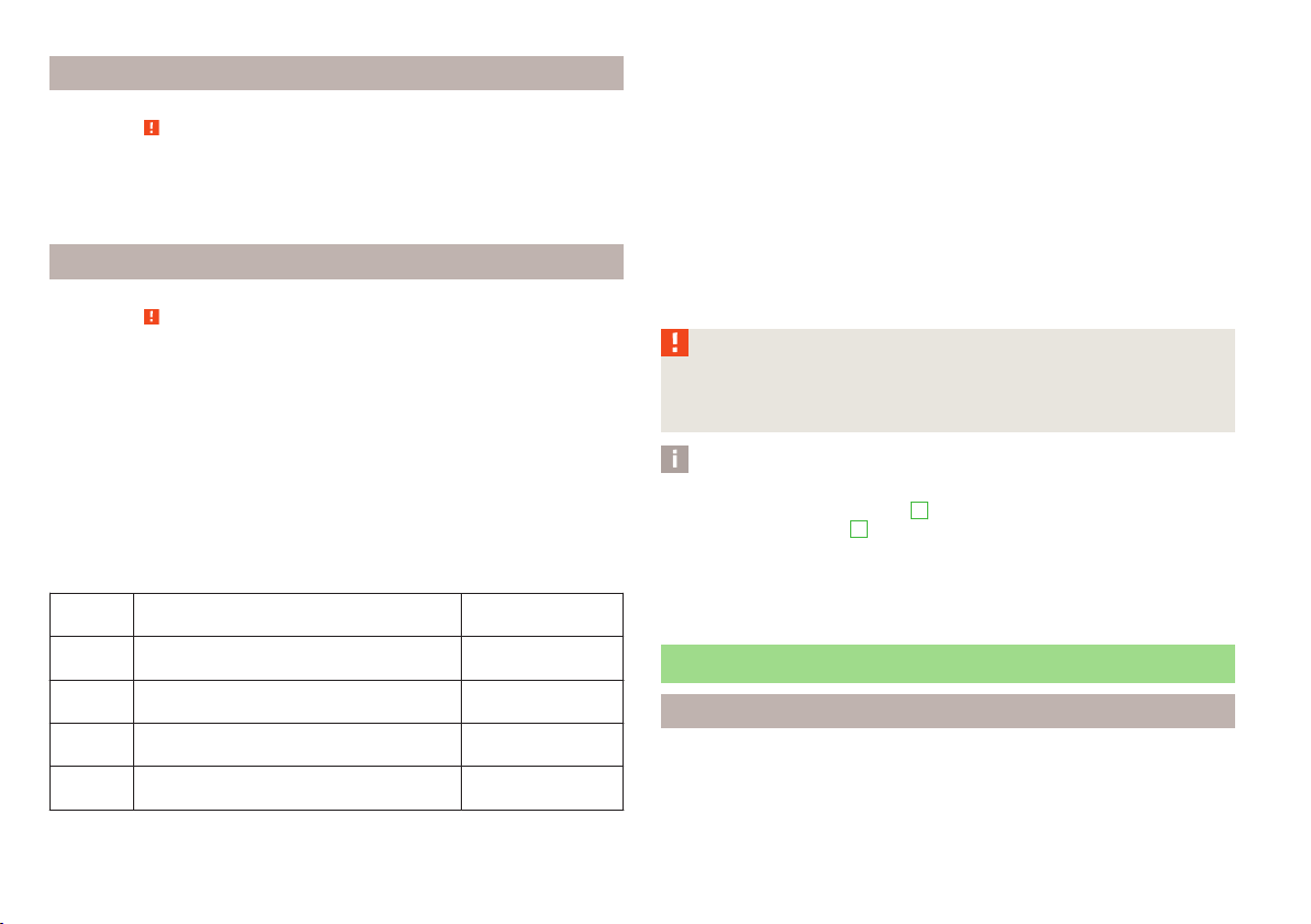
Abbreviations
Abbreviation Definition
rpm Engine revolutions per minute
ABS Anti-lock brake system
AF Multi-purpose vehicles
AHL Adaptive headlights
AG Automatic gearbox
TCS Traction control
CO2 in g/km discharged quantity of carbon dioxide in grams per driven kilo-
meter
DPF Diesel particle filter
DSG Automatic double clutch gearbox
DSR Active driver-steering recommendation
EDL Electronic differential lock
EPC EPC fault light
ESC Electronic Stability Control
FSI Stratified petrol direct injection
kW Kilowatt, measuring unit for the engine output
MG Manual gearbox
MFD Multifunction display
N1 Panel van intended exclusively or mainly for the transporta-
tion of goods
Nm Newton meter, measuring unit for the engine torque
TDI CR Diesel engine with turbocharging and common rail injection
system
TDI PD Diesel engine with injection system and unit injector injection
system
TSI Petrol engine with turbocharging and direct injection
Ð
Abbreviations
5
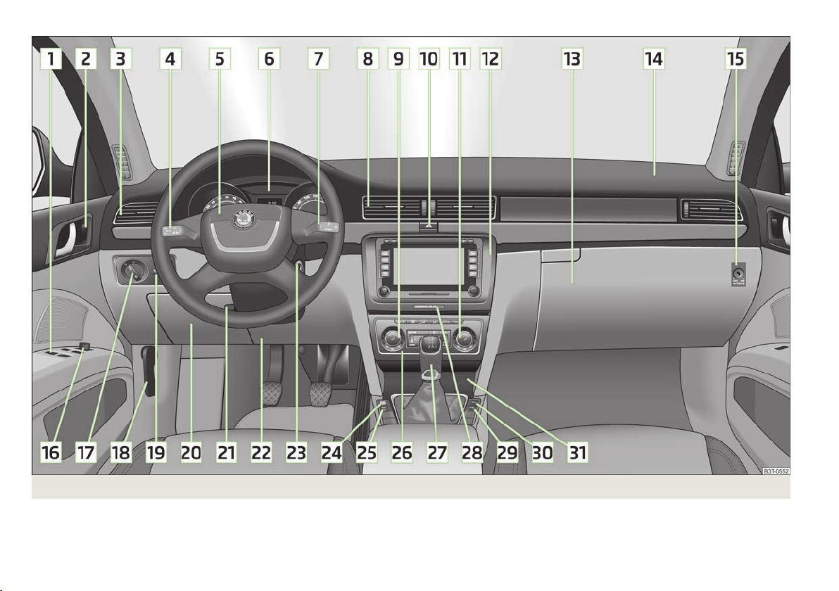
Fig. 1 Cockpit
6
Using the system
Using the system
Cockpit
Overview
1
Electric windows 40
2
Central locking system 30
3
Air outlet vents 94
4
Lever for the multifunction switch:
Turn signal light, headlight and parking light, headlight flasher 54
›
Speed regulating system 116
›
5
Steering wheel:
With horn
›
With driver’s front airbag 149
›
with pushbuttons for radio, navigation system and mobile
›
phone 127, 137
6
Instrument cluster: Instruments and indicator lights 8
7
Lever for the multifunction switch:
Multifunction display 12
›
Windscreen wiper and wash system 59
›
8
Air outlet vents 94
9
Regulator for front left seat heating 69
10
Switch for hazard warning lights 53
11
Regulator for front right seat heating 69
12
Depending on equipment fitted:
Radio
›
Navigation system
›
13
Storage compartment on the front passenger side 85
14
Front passenger airbag 149
15
Key switch for switching off the front passenger airbag (in front
passenger storage compartment) 153
16
Electric exterior mirror adjustment 64
17
Light switch 49
18
Bonnet release lever 177
19
Regulator for the instrument lighting and regulator for the headlight beam range adjustment 53, 53
20
Storage compartment on the driver's side 86
21
Lever for adjusting the steering wheel 104
22
Driver’s knee airbag 150
23
Ignition lock 105
24
TCS switch 111
25
Tyre pressure monitoring system 25
26
Depending on equipment fitted:
Operating controls for the air conditioning system 94
›
Operating controls for Climatronic 97
›
27
Depending on equipment fitted:
Gearshift lever (manual gearbox) 112
›
Selector lever (automatic gearbox) 121
›
28
Warning light for the deactivated front seat passenger airbag 153
29
Park Assist 113
30
Front and rear parking aid 112
31
Depending on equipment fitted:
Ashtrays 83
›
Storage compartment 86
›
Note
The arrangement of the controls and switches and the location of some items on
right-hand drive models may differ from that shown in » Fig. 1. The symbols on
the controls and switches are the same as for left-hand drive models.
Ð
Cockpit
7
Instruments and Indicator Lights
Instrument Cluster
ä Introduction
This chapter contains information on the following subjects:
Overview of the Instrument cluster 8
Engine revolutions counter 9
9
Coolant temperature gauge 9
Fuel gauge 9
Counter for distance driven 10
Service Interval Display 10
Digital clock 11
Recommended gear 11
Display in rear centre console 12
WARNING
■
Concentrate fully at all times on your driving! As the driver you are fully re-
sponsible for the operation of your vehicle.
■
Never operate the controls in the instrument cluster while driving, only
when the vehicle is stationary!
Overview of the Instrument cluster
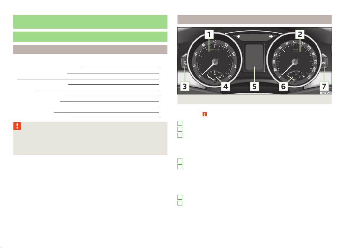
Fig. 2 Instrument cluster
First read and observe the introductory information and safety warnings on page 8.
ä
1
Engine revolutions counter » page 9
2
Speedometer » page 9
3
Button for display mode:
Setting the hours/minutes
›
Activating/deactivating the second speed in mph or km/h
Ð
›
Service intervals - Display of the number of days and kilometres remaining
›
until the next Inspection Service
4
Coolant temperature gauge » page 9
5
Display:
With counter for distance driven » page 10
›
With service interval display » page 10
›
With digital clock » page 11
›
With multifunction display » page 12
›
With information display » page 15
›
6
Fuel gauge » page 9
7
Button for:
Reset trip counter for the distance driven
›
Resetting Service Interval Display
›
Set hours/minutes
›
Activate/deactivate display mode
›
Ð
8
Using the system

Engine revolutions counter
First read and observe the introductory information and safety warnings on page 8.
ä
The red scale of the rev counter 1 » Fig. 2 on page 8 indicates the range in which
the engine control unit begins to limit the engine speed. The engine control unit
restricts the engine speed to a steady limit.
You should shift into the next higher gear before the red scale of the revolution
counter is reached, or move the selector lever into position D if your car is fitted
with an automatic gearbox.
To maintain the optimum motor speed, observe the gearshift indicator » page 11.
For the sake of the environment
Shifting to a higher gear in good time helps to lower fuel consumption, minimises
operating noise levels, protects the environment and contributes to a longer life
and reliability of the engine.
First read and observe the introductory information and safety warnings on page 8.
ä
Warning against excessive speeds
An audible warning signal will sound when the vehicle speed exceeds 120 km/h.
The audible warning signal is switched off when the vehicle speed falls below
this speed limit.
Note
This function is only valid for some countries.
Coolant temperature gauge
First read and observe the introductory information and safety warnings on page 8.
ä
The coolant temperature gauge 4 » Fig. 2 on page 8 operates only when the ignition is switched on.
The following guidelines regarding the temperature ranges must be observed to
avoid any damage to the engine.
Cold range
If the pointer is still in the left area of the scale it means that the engine has not
yet reached its operating temperature. Avoid high speeds, full throttle and high
engine loads.
The operating range
The engine has reached its operating temperature as soon as the pointer moves
into the mid-range of the scale, for a normal style of driving. The pointer may also
move further to the right at high engine loads and high outside temperatures.
CAUTION
Additional headlights and other attached components in front of the fresh air inlet impair the cooling efficiency of the coolant. There is then a risk of the engine
overheating at high outside temperatures and high engine loads » page 21,
Coolant temperature/coolant level .
Ð
Fuel gauge
First read and observe the introductory information and safety warnings on page 8.
ä
The fuel gauge 6 » Fig. 2 on page 8 only operates when the ignition is switched
on.
The fuel tank has a capacity of about 60 litres. The indicator light in the instrument cluster lights up when the pointer reaches the reserve marking» page 24.
Ð
CAUTION
Never drive until the fuel tank is completely empty! An irregular supply of fuel can
lead to irregular engine running. Unburnt fuel may get into the exhaust system
and damage the catalytic converter.
Ð
£
Instruments and Indicator Lights
9

Note
After filling up, it can occur that during dynamic driving (e.g. numerous curves,
braking, driving downhill and climbing a steep hill) the fuel gauge indicates approx. a fraction less. When stopping or during less dynamic driving, the fuel gauge
displays the correct fuel level again. This is not a fault.
Counter for distance driven
First read and observe the introductory information and safety warnings on page 8.
ä
Daily trip counter (trip)
The trip counter shows the distance driven since the time the counter was last
reset.
To reset the display of the daily trip counter, press button 7 » Fig. 2 on page 8
for longer.
Odometer
The odometer indicates the total distance in kilometres or miles which the vehicle
has been driven.
Fault display
If there is a fault in the instrument cluster Error will appear continuously in the
display. Ensure the fault is rectified as soon as possible by ŠKODA a specialist garage.
Note
For vehicles fitted with the information display, if the display of the second speed
is activated in mph or km/h, this driving speed is indicated instead of the counter
for the total distance driven.
Service Interval Display
First read and observe the introductory information and safety warnings on page 8.
ä
Service Interval Display
Before the next service interval, a key symbol and the remaining kilometres
are indicated on the display for several seconds after switching on the ignition. At
the same time, the remaining days until the next service interval are displayed.
The following is displayed in the information display:
Ð
Service in ... km or ... days.
The kilometre indicator or the days indicator reduces in steps of 100 km or, where
applicable, days until the service due date is reached.
As soon as the due date for the service is reached, a flashing key symbol and
the text Service appears in the display for several seconds after the ignition has
been switched on.
The following is displayed in the information display:
Service now!
Displaying the distance and days until the next service interval
You can use the button 3 to display the remaining distance and days until the
next service interval » Fig. 2 on page 8.
A key symbol and the remaining distance appear for several seconds in the
display. At the same time, the remaining days until the next service interval are
displayed.
On vehicles which are equipped with the information display, you can call up this
display in the menu Settings » page 16.
Resetting Service Interval Display
It is only possible to reset the Service Interval Display, if a service message or at
least a pre-warning is shown in the instrument cluster display.
We recommend that this reset is completed by a ŠKODA specialist garage.
The ŠKODA specialist garage:
Ð
Resets the memory of the display after the appropriate inspection
›
Adds an entry to the Service Schedule
›
Affixes the sticker with the entry of the following service interval to the side of
›
the dashboard on the driver's side
Reset the service interval display by using the reset button 7 » Fig. 2 on page 8.
On vehicles which are equipped with the information display, you can reset the
Service Interval Display in the menu Settings » page 16.
£
10
Using the system
CAUTION
We recommend that you do not reset the Service Interval Display yourself as this
can result in the incorrect setting of the Service Interval Display, which can also
cause possible problems with the operation of your vehicle.
Note
■
Never reset the display between service intervals, as this will result in the incor-
rect display.
■
Information is retained in the Service Interval Display even after the vehicle bat-
tery is disconnected.
■
If the instrument cluster is exchanged after a repair, the correct values must be
entered in the counter for the Service Interval Display. This work is carried out by
a ŠKODA specialist garage.
■
After resetting the display with flexible service intervals, the displayed data is
the same as that for a vehicle with fixed service intervals. We therefore recommend that the Service Interval Display is only reset by a
who will reset the display with a vehicle system tester.
■
For more information on the service intervals » Service Plan.
ŠKODA Service Partner,
Digital clock
First read and observe the introductory information and safety warnings on page 8.
ä
The clock is set with the buttons 3 and 7 » Fig. 2 on page 8.
Select the display that you wish to change with the button 3 and carry out the
change with the button 7.
On vehicles that are fitted with the information display, it is also possible to set
the clock in the menu Time » page 16.
Recommended gear
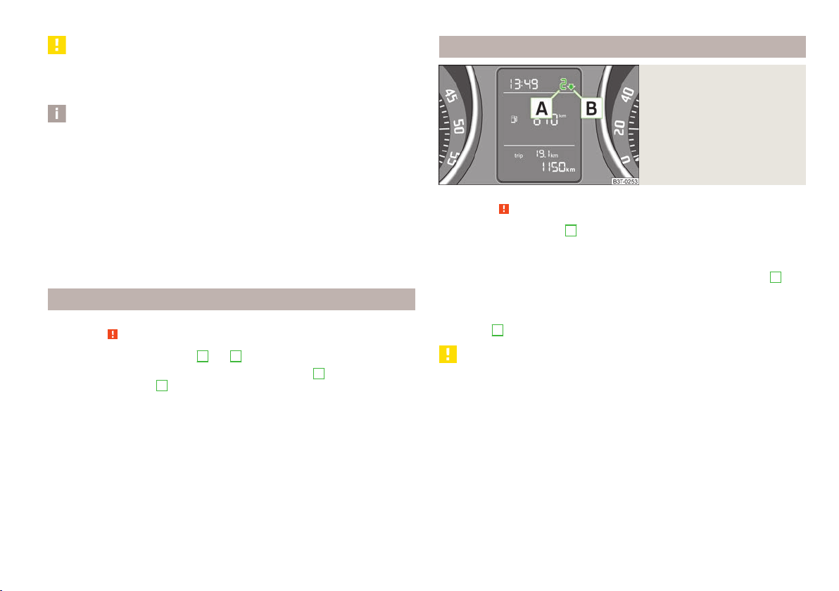
Fig. 3
Recommended gear
First read and observe the introductory information and safety warnings on page 8.
ä
The currently engaged gear A is shown in the instrument cluster display » Fig. 3.
In order to minimise the fuel consumption, a recommendation for shifting into an-
other gear is indicated in the display.
Ð
If the control unit recognises that it is beneficial to change gear, an arrow B is
shown in the display. The arrow points up or down, depending on whether you
should shift into a higher or lower gear.
At the same time, the recommended gear is indicated instead of the currently engaged gear A.
CAUTION
The driver is always responsible for selecting the correct gear in different driving
situations, such as overtaking.
Ð
Ð
Instruments and Indicator Lights
11
Display in rear centre console
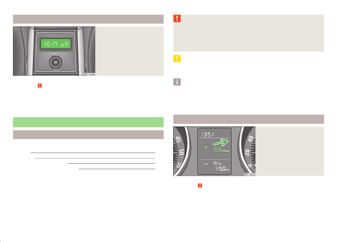
Fig. 4
Centre console at rear: Display
First read and observe the introductory information and safety warnings on page 8.
ä
The time and the outside temperature is displayed on the display in the rear centre console when the ignition is switched on » Fig. 4.
The values are taken over by the instrument cluster.
WARNING
■
Concentrate fully at all times on your driving! As the driver you are fully re-
sponsible for the operation of your vehicle.
■
Do not only rely upon the information given on the outside temperature display that there is no ice on the road. Even at temperatures around +4 °C, black
ice may still be on the road surface – warning, drive with care!
CAUTION
Pull out the ignition key if coming in contact with the display (e.g. when cleaning)
to prevent any possible damage.
Note
■
In certain national versions the displays appear in the Imperial system of meas-
ures.
■
If the display of the second speed is activated in mph, the current speed is not
indicated in km/h on the display.
Ð
Ð
Multifunction display (onboard computer)
ä Introduction
This chapter contains information on the following subjects:
Memory 12
Operation 13
Multifunction display details 13
Warning against excessive speeds 15
The multifunction display can only be operated when the ignition is switched on.
After the ignition is switched on, the function displayed is the one which you last
selected before switching off the ignition.
The multifunction display appears in the display » Fig. 5 on page 12 or in the information display » page 15.
On vehicles with an information display, there is an option to fade out some of
the information.
12
Using the system
Memory
Fig. 5
Multifunction display
First read and observe the introductory information and safety warnings on page 12.
ä
The multifunction display is equipped with two automatic memories. The selected
memory is shown in the Display » Fig. 5.
The data of the single-trip memory (memory 1) is shown if a 1 appears in the display. A 2 shown in the display means that data relates to the total distance memory (memory 2).
£
Switching over the memory using the button B » Fig. 6 on page 13 on the windscreen wiper lever or using the adjustment wheel D on the multifunction steering wheel.
Single-trip memory (memory 1)
The single-trip memory collates the driving information from the moment the ignition is switched on until it is switched off. New data will also flow into the calculation of the current driving information if the trip is continued within 2 hours
after switching off the ignition. If the trip is interrupted for more than 2 hours,
the memory is automatically erased.
Total-trip memory (memory 2)
The total-trip memory gathers data from any number of individual journeys up to
a total of 19 hours and 59 minutes driving or 1 999 kilometres driven, and on vehicles which are fitted with an information display up to a total of 99 hours and
59 minutes driving or 9 999 kilometres driven. The memory is deleted when either of these limits is reached and the calculation starts all over again.
Unlike the single-trip memory, the total-trip memory is not deleted after a period
of interruption of driving of 2 hours.
Note
All information in the memory 1 and 2 is erased if the battery of the vehicle is disconnected.
Operation
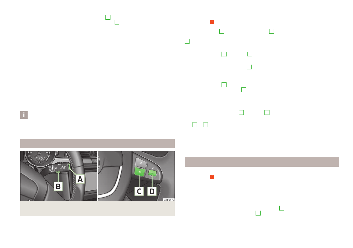
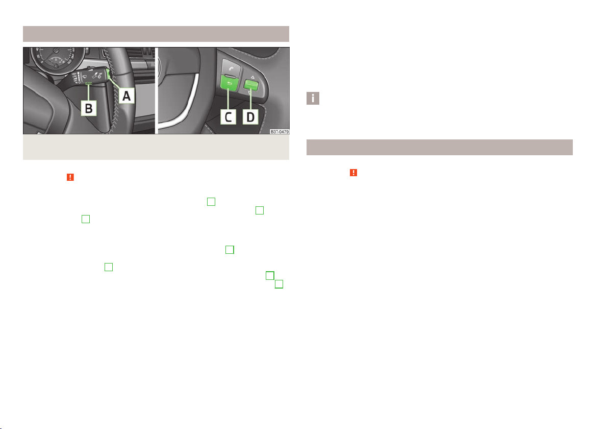
Fig. 6 Multifunction display: Control elements on the windscreen wiper lever/control elements on the multifunction steering wheel
First read and observe the introductory information and safety warnings on page 12.
ä
The rocker switch A » Fig. 6 and the button B are located on the windscreen
wiper lever. Switching over and resetting is performed with the adjustment wheel
D
on the multifunction steering wheel.
Select memory
Press the button B » Fig. 6 or D.
›
Selecting functions using the windscreen wiper lever
Briefly press the rocker switch A » Fig. 6 up or down. This opens the individual
›
functions of the multifunction display one after the other.
Selecting functions using the multifunction steering wheel
Press the button C » Fig. 6 to open the menu of the multifunction display.
›
Turn the adjustment wheel D upwards or downwards. This opens the individu-
›
al functions of the multifunction display one after the other.
Reseting
Select the desired memory.
›
Press and hold the button B » Fig. 6 or D for a short while.
›
The following readouts of the selected memory will be set to zero with the but-
ton B or D:
Ð
Average fuel consumption
›
Distance driven
›
Average speed
›
Driving time
›
Multifunction display details
First read and observe the introductory information and safety warnings on page 12.
ä
Outside temperature
The current outside temperature is shown in the display.
If the outside temperature drops below +4 °C, a snow flake symbol (warning sig-
nal for ice on the road) appears before the temperature indicator and an audible
signal will sound. After pressing the rocker switch A » Fig. 6 on page 13 at the
windscreen wiper lever or the button C at the multifunction steering wheel, the
function shown last is indicated.
Ð
£
Instruments and Indicator Lights
13

Driving time
The driving time which has elapsed since the memory was last erased, appears in
the display. If you wish to measure the driving time from a particular point in time,
you must set the memory to zero at this point in time by pressing the button
B
» Fig. 6 on page 13 on the windscreen wiper lever or the adjustment wheel
D
on the multifunction steering wheel.
The maximum time indicated in both memories is 19 hours and 59 minutes and on
vehicles which are fitted with an information display, it is 99 hours and 59 minutes. The indicator is set back to zero if this period is exceeded.
Current fuel consumption
The current fuel consumption level is shown in the display in litres/100 km1). You
can use this information to adapt your driving style to the desired fuel consumption.
The display appears in litres/hour if the vehicle is stationary or driving at a low
speed2).
Average fuel consumption
The average fuel consumption since the memory was last erased is shown in the
display in litres/100 km1) » page 12.
If you wish to determine the average fuel consumption over a certain period of
time, you must set the memory to zero at the start of the measurement using the
button B » Fig. 6 on page 13 on the windscreen wiper lever or the adjustment
wheel D on the multifunction steering wheel. After erasing the memory, no value appears in the display until you have driven approx. 300 m.
The display is updated regularly while you are driving.
Range
The estimated range in kilometres is shown on the display. It indicates the distance you can still drive with your vehicle based on the level of fuel in the tank
and the same style of driving.
The display is shown in steps of 10 km. After lighting up of the indicator light
the display is shown in steps of 5 km.
The fuel consumption over the last 50 km is used to calculate the range. The
range will increase if you drive in a more economical manner.
If the memory is set to zero (after disconnecting the battery), the fuel consumption of 10 ltr./100 km is calculated for the range; afterwards the value is adapted
accordingly to the style of driving.
Distance travelled
The distance driven since the memory was last erased appears in the display » page 12. If you wish to measure the distance driven from a particular time,
you must set the memory to zero at this point in time by pressing the button
B
» Fig. 6 on page 13 on the windscreen wiper lever or the adjustment wheel
D
on the multifunction steering wheel.
The maximum distance indicated in both memories is 1 999 km or 9 999 km on
vehicles with an information display. The indicator is set back to zero if this period
is exceeded.
Average speed
The average speed since the memory was last erased is shown in the display in
km/hour » page 12. If you wish to determine the average speed over a certain period of time, you must set the memory to zero at the start of the measurement
using the button B » Fig. 6 on page 13 on the windscreen wiper lever or the adjustment wheel D on the multifunction steering wheel.
After erasing the memory, no value appears in the display until you have driven
approx. 300 m.
The display is updated regularly while you are driving.
Current speed
The current speed which is identical to the display of the speedometer 2 » Fig. 2
on page 8 is indicated on the display.
Oil temperature
If the oil temperature is lower than 50 °C or if a fault in the system for checking
the oil temperature is present, only - -.- is displayed instead of the oil temperature.
Ð
1)
On some models in certain countries, the display appears in kilometres/litre.
2)
On some models in certain countries, - -.- km/ltr. is displayed when the vehicle is stationary.
14
Using the system
Warning against excessive speeds
First read and observe the introductory information and safety warnings on page 12.
ä
Adjust the speed limit while the vehicle is stationary
With the button A » Fig. 6 on page 13 on the windscreen wiper lever or the
›
adjustment wheel D on the multifunction steering wheel, select the menu item
Warning against excessive speeds.
Activate the option for setting the speed limit (the value flashes) with the but-
›
ton B on the windscreen wiper lever, or the adjustment wheel D on the multifunction steering wheel.
Set the desired speed limit, e.g. 50 km/h, with the button A on the windscreen
›
wiper lever or the adjustment wheel D on the multifunction steering wheel.
Use the button B on the windscreen wiper lever or the adjustment wheel
›
on the multifunction steering wheel to confirm the desired speed limit, or wait a
few seconds and the setting is saved automatically (the value stops flashing).
This allows you to set the speed in 5 km/h intervals.
Adjusting the speed limit while the vehicle is moving
With the button A » Fig. 6 on page 13 on the windscreen wiper lever or the
›
adjustment wheel D on the multifunction steering wheel, select the menu item
Warning against excessive speeds.
Drive at the desired speed, e.g. 50 km/h.
›
Use the button B on the windscreen wiper lever or the adjustment wheel
›
on the multifunction steering wheel to accept the current speed as the speed
limit (the value flashes).
If you wish to change the set speed limit, it is changed in 5 km/h intervals (e.g. the
accepted speed of 47 km/h increases to 50 km/h or decreases to 45 km/h).
Press repeatedly the button B on the windscreen wiper lever or use the ad-
›
justment wheel D on the multifunction steering wheel to confirm the desired
speed limit, or wait a few seconds and the setting is saved automatically (the
value stops flashing).
Change or delete speed limit
With the button A » Fig. 6 on page 13 on the windscreen wiper lever or the
›
adjustment wheel D on the multifunction steering wheel, select the menu item
Warning against excessive speeds.
Pressing the button B on the windscreen wiper lever or the adjustment wheel
›
D
on the multifunction steering wheel deletes the speed limit.
D
D
Pressing the button B on the windscreen wiper lever or the adjustment wheel
›
D
on the multifunction steering wheel again activates change mode for the
speed limit.
If the set speed limit is exceeded, an audible signal will sound as a warning. At
the same time the message Warning against excessive speeds appears on the
display with the set limit value.
The set speed limit value remains stored even after switching off the ignition.
MAXI DOT (information display)
ä Introduction
This chapter contains information on the following subjects:
Main menu 16
Settings 16
Door, boot lid and bonnet warning 18
Auto Check Control 18
The information display provides you with information on the current operating
state of your vehicle. The information system also provides you with data relating
to the radio, mobile phone, multifunction display, navigation system, the unit con-
nected to the MDI port and the automatic gearbox » page 121.
WARNING
Concentrate fully at all times on your driving! As the driver you are fully responsible for the operation of your vehicle.
CAUTION
Pull out the ignition key if coming in contact with the display (e.g. when cleaning)
to prevent any possible damage.
Ð
Ð
Instruments and Indicator Lights
15
Main menu
The menu items Audio and Navigation are only displayed when the factory-fitted
radio or navigation system is switched on.
The menu item Aux. heating is only displayed if a factory-fitted auxiliary heating
is installed.
The menu item Assistants is only then displayed if the vehicle is fitted with fatigue detection.
Note
If the information display is not activated at that moment, the menu always shifts
to one of the higher levels after approx. 10
seconds.
Ð
Fig. 7 Information display: Control elements on the windscreen wiper lever/
control elements on the multifunction steering wheel
First read and observe the introductory information and safety warnings on page 15.
ä
Operating with the buttons on the windscreen wiper lever
Activate the Main menu by pressing the rocker switch A » Fig. 7 for longer.
›
Individual menu items can be selected by means of the rocker switch A. When
›
the pushbutton B is briefly pressed, the information you have selected is displayed.
Operating with the buttons on the multifunction steering wheel
Activate the Main menu by pressing and holding the button C » Fig. 7 for a
›
short while.
By briefly pressing the C button you will reach one level higher.
›
The individual menus can be selected by pressing the adjustment wheel D.
›
The selected menu is displayed after briefly pressing the adjustment wheel D.
You can select the following information:
■
MFD » page 12
■
Audio » Operating instructions for the radio
■
Navigation » Operating instructions for the navigation system
■
Phone » page 126
■
Aux. Heating » page 100
■
Assistants » page 119
■
Vehicle status » page 18
■
Settings » page 16
16
Using the system
Settings
First read and observe the introductory information and safety warnings on page 15.
ä
You can change certain settings by means of the information display. The current
setting is shown on the information display in the respective menu at the top below the line.
You can select the following information:
■
Language
■
Autom. blind
■
MFD data
■
Convenience
■
Lights & Vision
■
Time
■
Winter tyres
■
Units
■
Assistants
■
Alternative speed displayed
■
Service
■
Factory setting
■
Back
Select the menu item Back to return to one level higher in the menu.
Language
You can set the language for the warning and information texts here.
£

Automatic blind (Combi)
This is where the automatic roll-up function of the boot roll cover can be deactivated/activated when opening the boot lid.
MFD displays
Activate or deactivate certain displays of the multifunction display here.
Comfort
This is where the following functions can be activated, deactivated or adjusted:
Switch on/off the function for automatically closing the
window and panoramic tilt/slide sunroof in a locked ve-
Rain closing
hicle when it starts raininga). If the function is set and it
is not raining, the windows including the panoramic tilt/
slide sunroof will close automatically after approx.
12 hours.
ATA confirm Switch on/off the audible signal indicating activation of
the anti-theft alarm system.
Central locking Switch on/off the central locking and automatic locking
function, also applies to the KESSY system.
Window op. Only convenience mode for the driver window or for all
of the windows can be adjusted here.
Mirror down Switch on/off the function for mirror lowering on the
front passenger side when engaging the reverse gearb).
Mirror adjust. Switch on/off the function for left and right exterior
mirror setting simultaneously.
Factory setting
a)
This function is only available on vehicles with a rain sensor.
b)
This function is only available on vehicles with an electrically adjustable driver seat.
Restore the Convenience factory setting.
Lights and Visibility
This is where the following functions can be activated, deactivated or adjusted:
Coming Home Switch on/off and adjust the light duration of the
COMING HOME function.
Leaving Home Switch on/off and adjust the light duration of the
LEAVING HOME function.
Footwell light
Switch on/off and adjust the footwell light intensity.
Dayl. dri. light
Rear wiper
(Heckwischer)
Lane ch. flash
Travel mode
Factory setting
Switch on/off the “DAY LIGHT” function.
Switch on/off the function for automatic rear window
wiping.
Switch on/off the convenience flashing function.
Switch on/off the travel model function.
Restore the factory setting for the lighting.
Time
The time, time format (12 or 24 hour indicator) and the changeover between sum-
mer/winter time can be set here.
Winter tyres
Here, you can set the speed at which an audible signal should sound. This func-
tion is, for example, used for winter tyres where the maximum permissible speed
is lower than the maximum speed of the vehicle.
When exceeding the speed, the following is shown on the information display:
Winter tyres: max. speed ... km/h
Units of measurement
The units for the temperature, consumption and distance driven can be set here.
Assistants
The tones of the audible signals for the parking aid can be adjusted here.
Second speed
The display of the second speed in mph or in km/h can be switched on here.
Service
Here you can have the remaining kilometres and days until the next service inter-
val displayed, and reset the Service Interval Display.
Factory Setting
After selecting the menu Factory setting the factory setting of the information
display is restored.
Ð
Instruments and Indicator Lights
17
Door, boot lid and bonnet warning
First read and observe the introductory information and safety warnings on page 15.
ä
If at least one door is open, or the boot or bonnet is open, the information display
indicates the relevant open door or boot/bonnet.
An audible signal also sounds if the vehicle is travelling at more than 6 km/h.
Auto Check Control
First read and observe the introductory information and safety warnings on page 15.
ä
Vehicle condition
Certain functions and conditions of individual vehicle systems are checked continuously when the ignition is switched on and also while driving.
Some error messages and other information are displayed in the information display. The messages are displayed at the same time as the symbols in the information display or the indicator lights in the instrument cluster » page 18.
If there is at least one error message, the menu item Vehicle status is displayed
in the menu. After selecting this menu the first of the error messages is displayed. Several error messages are shown on the display under the message e.g.
1/3. This indicates that the first of a total of three error messages is being displayed.
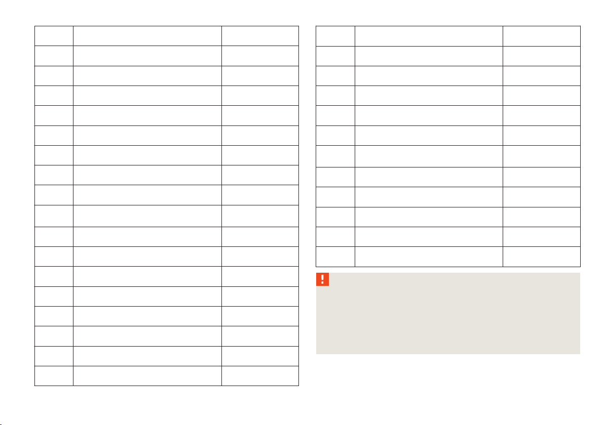
Warning symbols
Engine oil pressure too low » page 21
Clutches of the automatic gearbox are too
hot
Check engine oil level,
engine oil sensor faulty
Thickness of brake pads » page 25
Problem with engine oil pressure » page 18
» page 18
» page 22
Clutches of the automatic gearbox are too hot
A symbol in the information display indicates that the temperature of the
clutches of the automatic gearbox is too high.
The following is displayed in the information display:
Gearbox overheated. Stop! Owner's man.!
Stop the vehicle, switch off the engine, and wait until the symbol disappears risk of gearbox damage! You can continue your journey as soon as the symbol dis-
Ð
appears.
Problem with the engine oil pressure
If the symbol is shown in the information display, you must have your vehicle
checked immediately by a ŠKODA specialist garage. The information about the
maximum permissible engine speed is displayed together with this symbol.
WARNING
If you have to stop for technical reasons, then park the vehicle at a safe distance from the traffic, switch off the engine and activate the hazard warning
light system » page 53.
Note
■
If warning messages are shown in the information display, these messages
must be confirmed with the button B » Fig. 7 on page 16 on the windscreen wiper lever or with the button D on the multifunction steering wheel to call up the
main menu.
■
As long as the operational faults are not rectified, the symbols are always indi-
cated again. After they are displayed for the first time, the symbols continue to be
indicated without any extra messages for the driver.
Indicator lights
Overview
The indicator lights show certain functions/faults and may be accompanied by audible signals.
When switching on the ignition, some indicator lights illuminate briefly as a function test. These indicator lights will disappear several seconds after the vehicle is
started.
Ð
£
18
Using the system
Handbrake » page 20
Brake system » page 20
Fastening the seat belt » page 20
Generator » page 20
Open door » page 20
Engine oil pressure » page 21
Coolant temperature/coolant level » page 21
Bonnet » page 21
Boot lid » page 21
Power steering
Steering lock (KESSY system)
Engine oil level » page 22
Electronic stability control (ESC)
Traction control system (TCS)
Antilock brake system (ABS) » page 23
Rear fog light » page 23
Lamp failure
Adaptive headlights
Control system for exhaust » page 23
Glow plug system (diesel engine) » page 24
EPC fault light (petrol engine) » page 24
» page 21
» page 22
» page 23
» page 23,
» page 23
■
ing notes are not observed, this may result in severe injuries or major vehicle
damage.
■
injuries, scalding, accidents and fire when working in the engine compartment, e.g. inspecting and replenishing oil and other fluids. It is essential to observe safety notes »
Diesel particle filter (diesel engine) » page 24
Fuel reserve » page 24
Airbag system » page 25
Tyre control display » page 25
Windscreen washer fluid level » page 25
Thickness of brake pads » page 25
Turn signal (left/right). » page 25
Low beam » page 25
Fog lights » page 26
Speed regulating system » page 26
Selector lever lock
Starting (KESSY system)
Main beam » page 26
WARNING
If illuminated indicator lights and the corresponding descriptions and warn-
The engine compartment of your car is a hazardous area. There is a risk of
page 176, Engine compartment.
» page 26
Ð
Instruments and Indicator Lights
19

Handbrake
The indicator light comes on if the handbrake is applied. An audible warning is
also given if you drive the vehicle for at least 3 seconds at a speed of more than
6 km/h.
The following is displayed in the information display:
Release parking brake!
Brake system
The indicator light illuminates if the brake fluid level is too low or there is a
fault in the ABS.
The following is displayed in the information display:
Brake fluid: Owner's manual!
Stop the vehicle, switch off the engine, and check the level of the brake fluid » page 181 » .
WARNING
■
If you have to stop for technical reasons, then park the vehicle at a safe distance from the traffic, switch off the engine and activate the hazard warning
light system » page 53.
■
The following guidelines should be observed when opening the bonnet and
checking the brake fluid level » page 176, Engine compartment.
■
If the indicator light is displayed simultaneously with indicator light
» page 23, Antilock brake system (ABS) , do not continue your jour-
ney! Seek help from a ŠKODA specialist garage.
■
A fault to the braking system or the ABS system can increase the vehicle's
braking distance - risk of accident!
Seat belt indicator light
The indicator light comes on after the ignition is switched on as a reminder for
the driver and front passenger to fasten the seat belt. The indicator light only
goes out if the driver or front passenger has fastened his seat belt.
If the seat belt has not been fastened by the driver or front passenger, a permanent warning signal sounds at vehicle speeds greater than 20 km/h and simultaneously the indicator light flashes.
If the seat belt is not fastened by the driver or front passenger during the next
90 seconds, the warning signal is deactivated and the indicator light lights up
permanently.
Ð
Dynamo
If the indicator light lights up when the engine is running, the vehicle battery is
not being charged.
Seek help from a ŠKODA specialist garage. The electrical system requires checking.
WARNING
If you have to stop for technical reasons, then park the vehicle at a safe distance from the traffic, switch off the engine and activate the hazard warning
light system » page 53, Switches for the hazard warning light system.
CAUTION
If the indicator light (cooling system fault) comes on in addition to the indicator
light when driving, stop the vehicle immediately and switch the engine off risk of engine damage!
Open door
The indicator light comes on, if one or several doors are opened.
Ð
WARNING
If you have to stop for technical reasons, then park the vehicle at a safe distance from the traffic, switch off the engine and activate the hazard warning
light system » page 53.
Ð
Ð
Ð
20
Using the system

Engine oil pressure
When the indicator light is flashing , the engine oil pressure is too low.
The following is displayed in the information display:
Oil Pressure: Engine off! Owner's manual!
Stop the vehicle, switch off the engine, and check the level of the engine
oil » page 178.
Even if the oil level is correct, do not drive any further if the indicator light is
flashing . Also do not leave the engine running at an idling speed.
Seek help from a ŠKODA specialist garage.
WARNING
If you have to stop for technical reasons, then park the vehicle at a safe distance from the traffic, switch off the engine and activate the hazard warning
light system » page 53.
Coolant temperature/coolant level
If the indicator light lights up or flashes, either the coolant temperature is too
high or the coolant level is too low.
The following is displayed in the information display:
Check coolant! Owner's manual!
Stop the vehicle, switch off the engine, check the level of the coolant » page 180,
and refill the coolant if necessary » page 180.
If the coolant is within the specified range, the increased temperature may be
caused by an operating problem at the radiator fan. Check the fuse for the radia-
tor fan, replace if necessary » page 209, Fuses in the engine compartment.
If the indicator light does not go off even though the coolant level is correct
and the fuse for the fan is in working order do not continue driving!
Seek help from a ŠKODA specialist garage.
WARNING
■
If you have to stop for technical reasons, then park the vehicle at a safe distance from the traffic, switch off the engine and activate the hazard warning
light system » page 53.
■
Carefully open the coolant expansion bottle. If the engine is hot, the cooling
system is pressurized - risk of scalding! It is therefore best to allow the engine
to cool down before removing the cap.
■
Do not touch the radiator fan. The radiator fan may switch itself on automatically even if the ignition is off.
Bonnet
The indicator light comes on if the bonnet is unlocked.
WARNING
Ð
If you have to stop for technical reasons, then park the vehicle at a safe distance from the traffic, switch off the engine and activate the hazard warning
light system »
page 53.
Boot lid
The indicator light comes on if the boot lid is opened.
WARNING
If you have to stop for technical reasons, then park the vehicle at a safe distance from the traffic, switch off the engine and activate the hazard warning
light system » page 53.
Power steering/steering lock (KESSY system)
Power steering
If the indicator light lights up, this indicates a partial failure of the power steering and the steering forces can be greater. Seek help from a ŠKODA specialist garage.
Ð
Ð
Ð
£
Instruments and Indicator Lights
21

If the indicator light lights up, this indicates a complete failure of the power
steering and the steering assist has failed (significantly higher steering forces).
Seek help from a ŠKODA specialist garage.
Steering lock (KESSY system)
While the indicator light is flashing, the steering lock cannot be released. Fur-
›
ther information » page 105, KESSY system.
As long as the indicator light is flashing, an audible signal is beeping and the
›
following appears in the information display: Steering column lock: Workshop! ,
the electrical steering lock is faulty. Seek help from a ŠKODA specialist garage.
As long as the indicator light is flashing, an audible signal is beeping and the
›
following appears in the information display: Steering column lock faulty. the
electrical steering lock is faulty. Park the car, do not continue the journey. After switching off the ignition, it is then no longer possible to lock the steering,
to activate the electrical components (e.g. radio, navigation system), to switch
on the ignition again and to start the engine. Seek help from a ŠKODA specialist
garage.
WARNING
If you have to stop for technical reasons, then park the vehicle at a safe distance from the traffic, switch off the engine and activate the hazard warning
light system » page 53.
Note
If the vehicle battery has been disconnected and reconnected, the yellow indicator light comes on after switching on the ignition. The indicator light must go
out after driving a short distance. If the yellow indicator light does not go out
after starting the engine again and a short drive, it is necessary to visit a ŠKODA
specialist garage.
Engine oil level
The indicator light lights up (oil quantity too low)
The following is displayed in the information display:
Check oil level!
Stop the vehicle, switch off the engine, and check the level of the engine
oil » page 178.
The indicator light will go out if the bonnet is left open for more than 30 seconds.
If no engine oil has been replenished, the indicator light will come on again after
driving about 100 km.
The indicator light flashes (engine oil level sensor faulty)
The following is displayed in the information display:
Oil sensor: Workshop!
If the engine oil level sensor is faulty, the indicator light flashes several times
and an audible signal sounds when the ignition is turned on.
Seek help from a ŠKODA specialist garage.
WARNING
If you have to stop for technical reasons, then park the vehicle at a safe distance from the traffic, switch off the engine and activate the hazard warning
light system » page 53.
Electronic Stability Control (ESC)
The indicator light flashes to show that the ESC is currently operating.
If the indicator light comes on immediately after you start the engine, the ESC
might be switched off due to technical reasons. Switch the ignition off and on
again. If the indicator light does not light up after you switch the engine back on,
the ESR is fully functional again.
If the indicator light lights up, there is a fault in the ESC.
The following is displayed in the information display:
Ð
Error: Electronic Stability Control (ESC)
Seek help from a ŠKODA specialist garage.
Further information » page 110, Stabilisation Control (ESC).
Note
If the vehicle's battery has been disconnected and reconnected, the indicator
light comes on after switching on the ignition. The indicator light must go out
after driving a short distance.
Ð
Ð
22
Using the system

Traction control system (TCS)
The indicator light flashes to show that the ASR is currently operating.
If the indicator light comes on immediately after starting the engine, the ASR
can be switched off for technical reasons. Switch the ignition off and on again. If
the indicator light does not light up after you switch the engine back on, the ASR
is fully functional again.
If the indicator light lights up, there is a fault in the ASR.
The following is displayed in the information display:
Error: traction control (ASR)
Seek help from a ŠKODA specialist garage.
Further information » page 111, Traction control system (TCS).
Note
If the vehicle's battery has been disconnected and reconnected, the indicator
light comes on after switching on the ignition. The indicator light should go out
after driving a short distance.
Antilock brake system (ABS)
If the indicator light lights up, there is a fault in the ABS.
The following is displayed in the information display:
Error: ABS
The vehicle will only be braked by the normal brake system without the ABS.
Seek help from a ŠKODA specialist garage.
WARNING
■
If you have to stop for technical reasons, then park the vehicle at a safe distance from the traffic, switch off the engine and activate the hazard warning
light system » page 53.
■
If the indicator light » page 20 is displayed simultaneously with indicator
light , do not continue your journey!
garage.
■
A fault to the ABS system or the braking system can increase the vehicle's
braking distance - risk of accident!
Seek help from a ŠKODA specialist
The rear fog light
The indicator light comes on when the rear fog lights are operating » page 52.
Bulb failure
Ð
The indicator light comes on if a bulb is faulty:
within a few seconds of the ignition being switched on;
›
when switching on the defective light bulb.
›
The following is displayed in the information display:
Check front-right dipped beam!
Adaptive headlights
If the indicator light flashes for 1 minute while driving or after switching on the
ignition, there is a problem with the adaptive headlights » page 51.
Exhaust inspection system
If the indicator light lights up, there is a fault in the exhaust inspection system.
The engine control unit allows the vehicle to run in emergency mode.
Seek help from a ŠKODA specialist garage.
Ð
Ð
Ð
Ð
Ð
Instruments and Indicator Lights
23
Glow plug system (diesel engine)
The indicator light comes on after the ignition has been switched on. The engine can be started immediately after the pre-glow indicator light goes out.
There is a fault in the glow plug system if the indicator light does not come on
at all or lights up continuously.
If the indicator light begins to flash while driving, a fault exists in the engine
control. The engine control unit allows the vehicle to run in emergency mode.
Seek help from a
ŠKODA specialist garage.
EPC fault light (petrol engine)
If the indicator light lights up, there is a fault in the engine control. The engine
control unit allows the vehicle to run in emergency mode.
Seek help from a
ŠKODA specialist garage.
Diesel particulate filter (diesel engine)
The diesel particulate filter separates the soot particles from the exhaust. The
soot particles collect in the diesel particulate filter where they are burnt on a regular basis.
If the indicator light
filter.
To clean the diesel particle filter, the vehicle should be driven at an even speed of
at least 60 km/h »
nutes or until the indicator light goes out with the 4th or 5th gear engaged (automatic gearbox: position S) when the traffic situation permits it.
The indicator light only goes out after the diesel particulate filter has been
successfully cleaned.
If the filter is not properly cleaned, the indicator light does not go out and the
indicator light begins to flash.
The following is displayed in the information display:
Diesel particulate filter Owner's manual!
lights up, soot has accumulated in the diesel particulate
at engine speeds of 1 800 - 2 500 rpm for at least 15 mi-
The engine control unit allows the vehicle to run in emergency mode. After
switching the ignition off and on again the indicator light, the indicator light
also lights up.
Seek help from a ŠKODA specialist garage.
WARNING
■
The diesel particle filter achieves very high temperatures. Therefore do not
park in areas where the hot filter can come into direct contact with dry grass
or other combustible materials - risk of fire!
Ð
■
Always adjust your speed to suit weather, road, region and traffic conditions. The recommendations indicated by the indicator light must not tempt
you to disregard the national regulations for road traffic.
CAUTION
As long as the indicator light lights up, one must take into account an in-
Ð
creased fuel consumption and in certain circumstances a power reduction of the
engine.
Note
■
To assist the combustion process of the soot particles, we recommend that reg-
ularly driving over short distances should be avoided.
■
Using diesel fuel with an increased sulphur content can considerably reduce the
life of the diesel particle filter. A ŠKODA specialist garage will be able to tell you
which countries use only diesel fuel with high sulphur content.
Fuel reserve
The indicator light will come on if the fuel level is less than 9 litres.
The following is displayed in the information display:
Please refuel! Range ... km
Note
The text in the information display goes out only after refuelling and driving a
short distance.
Ð
Ð
24
Using the system

Airbag system
If the indicator light lights up, there is a fault in the airbag system.
The following is displayed in the information display:
Error: Airbag
The functionality of the airbag system is monitored electronically even if one of
the airbags is switched off.
If a front, side or head airbag or belt tensioner has been switched off using the
vehicle system tester:
The indicator light lights up for around 4 seconds after the ignition is switch-
›
ed on and then flashes for around 12 seconds.
The following is displayed in the information display:
Airbag/belt tensioner deactivated!
If the airbag was switched off using the key-operated switch on the side of the
dash panel on the passenger side:
The indicator light comes on for around 4 seconds after the ignition has been
›
switched on.
The switched off airbags are indicated in the middle of the dash panel by the
›
lighting up of the indicator light (airbag switched
off) » page 153.
Note
If the battery has been disconnected, the indicator light illuminates after the
ignition is switched on. The indicator light must go out after driving a short dis-
tance.
Windscreen washer fluid level
If the windscreen washer fluid level is too low, the indicator light comes on.
Top up with liquid » page 182, Windscreen washer system.
The following is displayed in the information display:
Top up wash fluid!
Thickness of brake pads
If the indicator light is slit, the brake pads are worn.
The following text will be displayed in the information display:
Check brake pads!
Seek help from a ŠKODA specialist garage.
Ð
Ð
Ð
WARNING
If there is a fault, have the airbag system checked immediately by a ŠKODA
specialist garage. Otherwise, there is a risk of the airbag not being activated in
the event of an accident.
Tyre control display
The indicator light lights up, if there is a substantial drop in inflation pressure
in one of the tyres. Check and adjust the pressure in all tyres » page 188, Service
life of tyres.
If the indicator light lights up, there is a fault in the system.
Seek help from a ŠKODA specialist garage.
Further information » page 192, Tyre control display.
Turn signal system
Either the left or right indicator light flashes depending on the position of
the turn signal lever.
Ð
If a turn signal light fails, the indicator light flashes at twice its normal rate.
Switching off the hazard indicator light system is switched on will cause all of the
turn signal lights as well as both indicator lights to flash.
Further information » page 54, Turn signal and main beam lever.
Low beam
The indicator light comes on when low beam is selected » page 49.
Instruments and Indicator Lights
Ð
Ð
25

Fog lights
The indicator light comes on when the fog lights are operating » page 52.
Speed regulating system
The indicator light comes on when the cruise control is operating » page 116.
Selector lever lock/starting (KESSY system)
If the indicator light lights up, operate the brake pedal. This is necessary to
move the selector lever from position P and N» page 124 or to start the engine in
vehicles with the KESSY system » page 107.
Main beam
The indicator light comes on when the main beam or headlight flasher are selected » page 54.
Ð
Ð
Ð
Ð
26
Using the system
Unlocking and locking
Vehicle key
Note
If you lose a key, please contact a ŠKODA Service Partner who will obtain a re-
placement key for you.
Ð
Introductory information
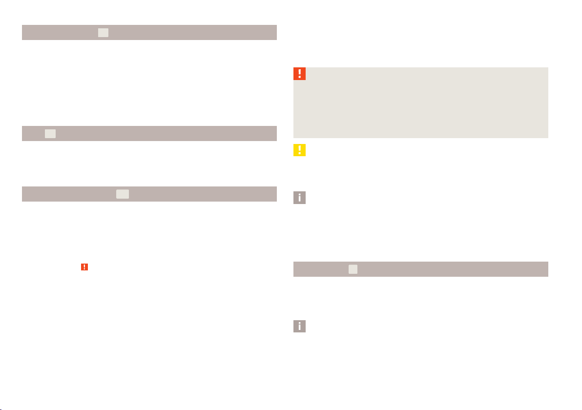
Fig. 8
Remote control key
Two remote control keys are provided with the vehicle » Fig. 8.
WARNING
■
Always withdraw the key whenever you leave the vehicle - even if it is only
for a short time. This is particularly important if children are left in the vehicle.
The children might otherwise start the engine or operate electrical equipment
(e.g. power windows) - risk of injury!
■
Do not withdraw the ignition key from the ignition lock until the vehicle has
come to a stop. The steering lock might otherwise engage unintentionally risk of accident!
CAUTION
■
Each key contains electronic components; therefore it must be protected
against moisture and severe shocks.
■
Keep the groove of the keys absolutely clean. Impurities (textile fibres, dust,
etc.) have a negative effect on the functionality of the locking cylinder and ignition lock.
Replacing the battery in the remote control key
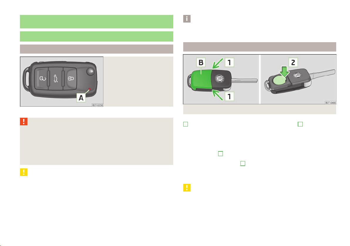
Fig. 9 Remote control key: Remove cover/remove battery
Each remote control key contains a battery which is housed under the cover
B
» Fig. 9. If the battery is discharged, the red indicator light A does not flash
after you press a button on the remote control key » Fig. 8 on page 27. We recommend that you ask a ŠKODA Service Partner to replace the key battery. However,
if you would like to replace the discharged battery yourself proceed as follows.
Flip out the key.
›
Press off the battery cover with your thumb or using a flat screwdriver in the
›
region of arrows 1 » Fig. 9.
Remove the discharged battery from the key by pressing the battery down-
›
wards in the region of arrow 2.
Insert the new battery. Ensure that the “+” symbol on the battery is facing up-
›
wards. The correct polarity is shown on the battery cover.
Place the battery cover on the key and press it down until it clicks into place.
›
CAUTION
■
Pay attention to the correct polarity when changing the battery.
■
The replacement battery must have the same specification as the original bat-
tery.
£
Unlocking and locking
27
For the sake of the environment
Dispose of the used battery in accordance with national legal provisions.
Note
■
Please approach a ŠKODA
new one for you.
■
The system has to be synchronised, if the vehicle cannot be unlocked or locked
with the remote control key after replacing the battery » page 32.
Service Partner if you lose a key as they can obtain a
Child safety lock
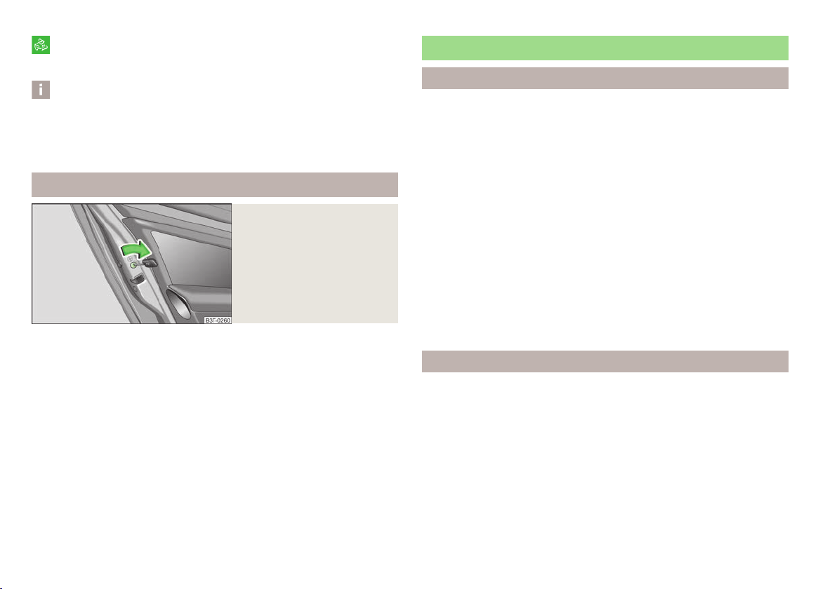
Fig. 10
Child safety locks on the rear
doors
The child safety lock prevents the rear door from being opened from the inside.
The door can only be opened from the outside.
You can switch the child safety lock on and off using the vehicle key.
Switching on
Use the vehicle key to turn the slit in the rear door in the direction of the ar-
›
row » Fig. 10.
Switching off
Use the vehicle key to turn the slit to the right in the opposite direction to the
›
arrow.
Central locking system
Introductory information
When using the central locking and unlocking system, all the doors and the fuel
filler flap are locked or unlocked at the same time (if it was not set differently in
the menu item Settings - Convenience
unlocked when opening. The boot lid can then be opened by pressing the handle
Ð
on the lower edge of the boot lid » page 36.
Indicator light in the driver's door
After locking the vehicle, the indicator light flashes for around 2 seconds in quick
succession, afterwards it begins to flash evenly at longer intervals.
If the vehicle is locked and the safe securing system » page 29 is not operating,
the indicator light in the driver door flashes for about 2 seconds fast, goes out
and starts to flash evenly at longer intervals after about 30 seconds.
If the indicator light first of all flashes fast for about 2 seconds, afterwards lights
up for about 30 seconds without interruption and then flashes slowly, there is a
fault in the system of the central locking or in the interior monitor and in the towing protection monitoring » page 34. Seek help from a ŠKODA specialist garage.
Convenience operation of windows
The windows can be opened and closed when unlocking and locking the vehicle » page 42.
Individual settings
Opening a single door
This selection function makes it possible to only unlock the driver's door. The other doors and the fuel filler flap remain locked and are only unlocked after being
opened again.
Unlocking a vehicle side door
Ð
This selection function enables to unlock both doors on the driver's side. The other doors and the fuel filler flap remain locked and are only unlocked after being
opened again.
Unlocking the vehicle with the KESSY system
This selection function enables to unlock all the doors, individual doors, both
doors on the left and right vehicle side or to unlock the driver and front passenger
door at the same time. The other doors and the fuel filler flap remain locked and
of the information display). The boot lid is
Ð
£
28
Using the system

are only unlocked after being unlocked again using the unlock button on the remote control key » Fig. 8 on page 27 or the central locking button » Fig. 11 on
page 30.
Automatic locking and unlocking
All the doors and the boot lid are locked automatically once the car reaches a
speed of about 15 km/h.
If the ignition key is withdrawn, the car is then automatically unlocked again. In
addition, it is possible for the driver or front passenger to unlock the car by pressing the central locking button » page 30.
The vehicle doors can also be unlocked and opened by pulling once on the door
opening lever.
WARNING
Locked doors prevent unwanted entry into the vehicle from outside, for example at road crossings. Locked doors do, however, make it more difficult for rescuers to get into the vehicle in an emergency - danger to life!
Note
■
You can have the individual settings activated by a ŠKODA Service Partner or
you can activate them yourself with the help of the information display » page 16,
Settings.
■
In the event of an accident in which the airbags are deployed, the locked doors
are automatically unlocked in order to enable rescuers to gain access to the vehicle.
■
Only the driver's door can be unlocked or locked using the key if the central
locking system fails » page 35. The other doors and the boot lid can be manually
locked or unlocked.
■
Emergency locking of the door » page 35.
■
Emergency unlocking of the boot lid » page 37.
The safe securing system can be deactivated within 2 seconds by double locking
the vehicle.
If the safe securing system is not in operation:
the indicator light in the driver door flashes rapidly for about 2 seconds, goes
›
out and starts to flash at regular, longer intervals after about 30 seconds;
is the filler flap locked.
›
The safe securing system is activated again the next time the vehicle is unlocked
and locked.
If the vehicle is locked and the safe securing system is deactivated, the vehicle
can be opened from the inside by pulling the door opening lever.
WARNING
If the vehicle is locked from the outside and the safe securing system is activated, there must not be any person in the vehicle as it is then no longer possible to open either a door or a window from the inside. The locked doors
make it more difficult for rescuers to get into the vehicle in an emergency hazard!
Note
■
The anti-theft alarm system is activated when the vehicle is locked even if the
safe securing system is deactivated. The interior monitor is however not activated.
■
After locking the vehicle, you will be informed that the safe securing system is
activated by means of the message CHECK DEADLOCK on the instrument cluster
display. On vehicles that are equipped with an information display, the following
message will appear Check deadlock! Owner's manual! appears.
Ð
Ð
Safe securing system
The central locking system is equipped with a safe securing system. The door
locks are blocked automatically if the vehicle is locked from the outside. The indicator light flashes for around 2 seconds in quick succession, afterwards it begins
to flash evenly at longer intervals. It is not possible to open the doors with the
door handle either from the inside or from the outside. This acts as an effective
deterrent for attempts to break into your vehicle.
Unlocking and locking
29

Vehicle locking/unlocking from the inside
Fig. 11
Central locking button
WARNING
The central locking system also operates if the ignition is switched off. Children should never be left unattended in the vehicle since it is difficult to provide assistance from the outside when the doors are locked. Locked doors
make it difficult for rescuers to get into the vehicle in an emergency - hazard!
Note
If the safe securing system is activated» page 29, the door opening lever and the
central locking buttons do not operate.
Ð
The doors and the boot lid can be unlocked/locked with the rocker switch on the
door opening lever of the driver or front passenger door » Fig. 11 even when the
ignition is not switched on.
The central locking button works only when the vehicle was not locked from the
outside and all doors are closed.
Locking
Press the symbol » Fig. 11 on the button. The symbol in the button comes on.
Unlocking
Press the symbol » Fig. 11 on the button. The symbol in the button is no longer
illuminated.
The following applies if your vehicle has been locked using the central locking
button.
It is not possible to open the doors or the boot lid from the outside (safety fea-
›
ture, e.g. when stopping at traffic lights etc.).
The vehicle doors can be unlocked and opened by pulling once on the door
›
opening lever.
In the event of an accident in which the airbags are deployed, the locked doors
›
are automatically unlocked from the inside in order to enable rescuers to gain
access to the vehicle.
By pressing and holding down the symbol or on the rocker switch in the driver's door, the windows can be conveniently closed or opened.
30
Using the system
Remote control
Introductory information
You can use the remote control key to:
unlock and lock the vehicle,
›
unlock or open the boot lid,
›
open and close the windows »
›
The transmitter with the battery is housed in the handle of the remote control
key. The receiver is located in the interior of the vehicle. The operating range of
the remote control key is approx. 30 m. But this range of the remote control can
be reduced if the batteries are weak.
The key has a fold-open key bit which can be used for unlocking and locking the
car manually and also for starting the engine.
If a lost key is replaced or if the receiver unit has been repaired or replaced, the
system must be initialised by a ŠKODA Service Partner. Only then can the remote
control key be used again.
Note
■
The remote control is automatically deactivated when the ignition is switched
on.
■
The operation of the remote control may temporarily be affected by interference from transmitters close to the car and which operate in the same frequency
range (e.g. mobile phone, TV transmitter).
page 42, Window convenience operation.
£

■
The battery must be replaced if the central locking or anti-theft alarm system
does react to the remote control at less than 3 metres away » page 27.
■
If the driver door is open, the vehicle cannot be locked using the remote control
key.
Locking/unlocking
Fig. 12
Remote control key
Unlocking the vehicle
Press the button 1 » Fig. 12.
›
Locking the vehicle
Press the button 3 » Fig. 12.
›
Deactivating the safe securing system
Press the button 3 » Fig. 12 twice within 2 seconds. Further informa-
›
tion » page 29.
Unlocking the small boot lid
Press the button 2 » Fig. 12. Further information » page 36.
›
Raising the small boot lid
Press the button 2 » Fig. 12. Further information » page 36.
›
Unlocking the boot lid (Combi)
Press the button 2 » Fig. 12. Further information » page 37.
›
Opening the boot lid (Combi)
Press the button 2 » Fig. 12. Further information » page 39.
›
Folding out the key bit
Press the button 4 » Fig. 12.
›
Folding in the key bit
Press the button 4 » Fig. 12 and fold in the key bit.
›
Unlocking
The turn signal lights flash twice as confirmation that the vehicle has been unlocked. If the vehicle is unlocked using button 1 » Fig. 12 and none of the doors
Ð
or the boot lid are opened within the next 30 seconds, the vehicle is automatically locked again and the safe securing system or anti-theft alarm system is reactivated. This function is intended to prevent the car being unlocked unintentionally.
In addition, when the car is unlocked, the electrically adjustable seats and exterior mirrors move into the position assigned to this key. The stored setting of driver
seat and exterior mirrors is retrieved.
Locking
The turn signal lights flash once to confirm that the vehicle has been correctly
locked.
If the doors or the boot lid remain open after the vehicle has been locked, the
turn signal lights do not flash until they have been closed.
When the vehicle is unlocked or locked, the interior lights and entry lighting are
automatically switched on or off via the door contact.
WARNING
If the car is locked from the outside and the safe securing system is activated,
there must not be any person in the car as it is then not possible to open either a door or a window from the inside. The locked doors make it more difficult for rescuers to get into the vehicle in an emergency - hazard!
Note
■
Only operate the remote control when the doors and boot lid are closed and the
vehicle is in your line of sight.
■
To avoid the car being locked inadvertently once in the car, the lock button
of the remote control must not be pressed before the key is inserted into the ignition lock. Should this happen, press the unlock button of the remote control.
■
The automatic raising of the small boot lid can be impaired at temperatures below +4 °C.
Ð
Unlocking and locking
31

Synchronisation
If the vehicle cannot be unlocked by actuating the remote control system then it
is possible that the code in the key and the control unit in the vehicle are no longer synchronised. This can occur when the buttons on the radio-operated key are
actuated a number of times outside of the operative range of the equipment or
the battery on the remote control was replaced.
This means it is necessary to synchronise the code as follows:
press any button on the remote control key;
›
pressing of the button means that the door will unlock with the key within 1 mi-
›
nute.
KESSY system
Introductory information
The KESSY system (Keyless Entry Start Exit System) enables a comfort unlocking
and locking of the vehicle and a start-up without actively using the remote control key. The KESSY system is integrated in the central locking system.
The safe securing system and anti-theft alarm system correspond to vehicles
without the KESSY system. Only the control elements are different.
When unlocking and locking the vehicle or for starting the engine it suffices to
carry the key with you, e.g. in your pocket.
Locking/unlocking
To lock/unlock a vehicle fitted with the KESSY system, it is necessary for the valid
remote control key to be located no more than around 1.5 m from the front door
handle or boot lid.
Unlocking the vehicle
Grab the door handle of the front door or cover the sensor 2 » Fig. 13 with the
›
whole palm of your hand.
Locking the vehicle
Touch the sensor 1 » Fig. 13 with your fingers.
›
Deactivating the safe securing system
Ð
Touch the sensor 1 » Fig. 13 twice within 2 seconds with your fingers.
›
Unlocking the boot lid
Press the handle of the boot lid.
›
Unlocking
If a valid remote control key is located in the area A » Fig. 13 or B of the vehicle,
it is possible to unlock the vehicle via the relevant door of the area in which the
key is located. In the area A, the vehicle can be unlocked by the handle of the
front left door, in the area C, the boot lid can be unlocked.
If you cover the sensor 2 at the same time as the sensor 1 when unlocking the
vehicle, it is not unlocked.
Locking
The driver door or front passenger door must be closed when locking. Do not grab
the door handle, otherwise the vehicle cannot be locked.
Ð
If the vehicle is fitted with the electric boot lid, the lid starts to open after pressing the handle.
After the boot lid is closed, it will be locked. On vehicles fitted with automatic
gearbox, the selector lever must be moved into the position P before unlocking.
Check locking
After locking the vehicle by means of the sensor 1 » Fig. 13, it is not possible to
unlock the vehicle using the sensor 2 for 2 seconds. Pull on the handle to check
if the vehicle is locked.
Fig. 13 KESSY: Designation of the areas and unlocking/locking the vehicle
32
Using the system
CAUTION
After leaving the vehicle, it does not lock automatically, the procedure for locking
the vehicle must therefore be observed.
£

Note
■
If the battery in the remote control key is weak or discharged, the vehicle may
not be unlocked or locked via the KESSY system. In this case, use the emergency
unlocking or emergency locking of the driver's door » page 35.
■
The KESSY system can find the valid key, even if it was left in the front area of
the vehicle's roof for example. Make sure you know where the valid remote control key is at all times.
■
When locking/unlocking the vehicle using the sensors 1 »
use gloves or other objects that might prevent the hand from coming into direct
contact with the sensor.
■
If you unlock the vehicle by means of the sensor in the handle and do not open
a door or the boot lid within the next 30
matically and the safe securing system or anti-theft alarm system will be reactivated. This function is intended to prevent the car being unlocked unintentionally.
seconds, the vehicle will lock again auto-
Fig. 13 or
2
do not
Protection against inadvertently locking the key in the vehicle
If the key, which was used to lock the vehicle, remains in the vehicle in the area
D
» Fig. 13 on page 32 after locking and closing all of the doors including the boot
lid, the protection against inadvertently locking the key in the vehicle is activated
and the vehicle unlocks itself again.
The following message is displayed in the information display or display of the instrument cluster: Key in vehicle. or KEY IN VEHICLE.
Additionally, on vehicles which are fitted with the anti-theft alarm system, an audible signal sounds.
Messages in the instrument cluster display
■
Key not found. or No Key
This message is displayed when you wish to start the engine and the system cannot detect a valid key in the vehicle. This can occur if the key is outside the vehicle, the battery in the key is discharged, the key is defective or the electromagnetic field is strongly disturbed. This message is also displayed when the ignition
is switched on or the engine is running and the system cannot detect a valid key
in the vehicle.
■
Keyless faulty. or CHECK KEYLESS.
Error in the KESSY system; seek help from a
ŠKODA specialist garage.
■
Renew key battery! or KEY BATTERY
Low voltage of the remote control key battery, change the battery.
Parking the vehicle
If the vehicle is not unlocked within 60 or 90 hours, the sensors 1 » Fig. 13 on
page 32 and 2 in the handle of the front passenger's door are automatically deactivated.
Activation after 60 hours
Unlock the driver's door using the sensor 2 » Fig. 13 on page 32.
›
Press the handle of the boot lid.
›
Unlock the vehicle using the button on the remote control key,
›
Ð
Unlocking the driver's door in an emergency » page 35.
›
Activation after 90 hours
Unlock the vehicle using the button on the remote control key,
›
Unlocking the driver's door in an emergency » page 35.
›
Anti-theft alarm system
Introductory information
The anti-theft alarm system increases the level of protection against people
seeking to break into the vehicle. The system triggers audible and visual warning
Ð
signals if an attempt is made to break into the vehicle.
How is the alarm system activated?
The anti-theft alarm system is activated when the vehicle is locked with the radio
remote control or the key in the driver's door . The door contact monitoring is activated approx. 15 seconds after the locking. The interior and the towing protection monitoring are activated approx. 30 seconds after the locking. If a door is
opened during activation, the monitoring is only activated 5 seconds after closing.
How is the alarm system deactivated?
The alarm system is deactivated by pressing the unlock button on the radio remote control. The anti-theft alarm system is reactivated if the vehicle is not
opened within 30 seconds after transmitting the radio signal.
The alarm system is also deactivated if you unlock the driver door using the key
within 45 seconds of locking the vehicle.
Ð
Ð
£
Unlocking and locking
33

If the vehicle is unlocked within 45 seconds by inserting the key into the driver
door, the key must be inserted into the ignition lock and the ignition switched on
within 15 seconds of unlocking the door to deactivate the alarm system. The
alarm is triggered if the ignition is not switched on within 15 seconds.
When is the alarm triggered?
The following security areas of the locked vehicle are monitored:
bonnet;
›
boot lid;
›
doors;
›
ignition lock;
›
Vehicle inclination » page 34;
›
Interior of the vehicle » page 34;
›
A drop in voltage of the on-board power supply;
›
Socket of the factory-fitted towing device.
›
An alarm is immediately triggered if either of the two battery terminals is disconnected while the anti-theft alarm system is activated.
How is the alarm switched off?
The alarm is switched off by unlocking the vehicle with the radio remote control
or switching on the ignition.
Note
■
The working life of the alarm siren is 5 years.
■
Before leaving the car, it must be checked that all of the windows, doors, and
the electric sliding/tilting roof or the panoramic sliding roof are properly closed to
ensure the full functionality of the anti-theft alarm system.
■
Coding of the radio remote control and the receiver unit precludes the use of
the radio remote control from other vehicles.
Interior monitor and towing protection monitoring
Fig. 14
Button for interior monitor and
towing protection monitoring
The interior monitor detects movements inside the car and then triggers the
alarm.
Switching off
Switch off the ignition.
›
Open the driver door.
›
Press the button » Fig. 14 on the centre column on the driver side, the sym-
›
bol that lights up in the button changes from red to orange.
Lock the vehicle within 30 seconds.
›
The interior monitor and the towing protection monitoring are switched on again
automatically the next time the car is locked.
Note
■
Switch off the interior monitor and the towing protection monitoring if there is
a possibility of the alarm being triggered by movements from (e.g. children or ani-
Ð
mals) within the vehicle interior or if the vehicle has to be transported (e.g. by
train or ship) or towed.
■
The opened glasses storage compartment reduces the effectiveness of the interior monitor. To ensure the full functionality of the interior monitor, the glasses
storage compartment must always be closed before locking the vehicle.
Ð
34
Using the system

Emergency unlocking and locking
Unlocking and locking the driver's door
After closing the door, it no longer be opened from the outside. The door can be
unlocked from the inside by pulling on the door handle again, and then opened
from the outside.
Ð
Fig. 15
Handle on the driver's door: covered locking cylinder
If the remote control key or the central locking system does not operate, the driver's door can be unlocked or locked manually.
Pull on the handle.
›
Push the vehicle key into the recess on the bottom side of the cover and fold
›
upwards.
Insert the vehicle key bit into the lock cylinder and unlock or lock the vehicle.
›
Locking a door
Fig. 16
Rear door: Emergency locking of
the door
An emergency locking mechanism is located on the face side of the doors which
have no locking cylinder, it is only visible after opening the door.
Remove the panel A » Fig. 16.
›
Insert the key into the slot B and turn it into the horizontal position in the di-
›
rection of the arrow (mirror-inverted on the right doors).
Replace the cover.
›
Boot lid
ä Introduction
This chapter contains information on the following subjects:
Twindoor - small boot lid 36
Twindoor - large boot lid 36
Boot lid (Combi) 37
Automatic locking 37
Emergency unlocking 37
WARNING
■
Ensure that the lock is properly engaged after closing the boot lid. Other-
wise, the boot lid might open suddenly when driving even if the boot lid lock
Ð
was closed - risk of accident!
■
Never drive with the boot lid fully opened or slightly ajar otherwise exhaust
gases may get into the interior of the vehicle - risk of poisoning!
■
Never position any body parts under the cover of the locking eye trim panel
for the boot lid lock - risk of injury!
■
Do not press on the rear window when closing the boot lid, it could crack -
risk of injury!
Note
■
After closing the boot lid, it is automatically locked within 1 second and the
anti-theft alarm system is activated. This applies only if the vehicle was locked
before closing the boot lid.
■
The function of the hand grip on the bottom edge of the boot lid is deactivated
when starting off or from a speed of more than 5 km/h. The function of the hand
grip is activated again after stopping the vehicle and after opening the driver or
front passenger door or after pressing the button 1 on the remote control key.
■
Repeated opening and closing of the boot lid can lead to a temporary failure of
the function due to the overheating protection of the motors of the Twindoor
system.
Ð
Unlocking and locking
35

Twindoor - small boot lid
Twindoor - large boot lid
Fig. 17 Handle of boot lid/opened small boot lid
First read and observe the introductory information and safety warnings on page 35.
ä
The small boot lid » Fig. 17 can be opened after unlocking the vehicle.
Opening
Press on the handle at the bottom side of the boot lid » Fig. 17 - and the boot
›
lid lifts up automatically » Fig. 17 - .
Closing
Pull down the boot lid and close it with a slight swing. The bonnet locks auto-
›
matically.
The small boot lid can also be opened by pressing the button on the remote
control key 2 for approx. 1 second.
A handle which makes the closing easier is located on the inner panelling of the
boot lid.
36
Using the system
Fig. 18 Handle of boot lid/opened large boot lid
First read and observe the introductory information and safety warnings on page 35.
ä
The large boot lid » Fig. 18 can be opened after unlocking the vehicle.
Opening
Press the handle 1 » Fig. 18 on the bottom edge of the boot lid.
›
Wait until the brake light 2 in the rear window flashes twice.
›
Press the handle 3 and simultaneously lift up the boot lid.
›
Closing
Pull down the boot lid and close it with a slight swing. The bonnet locks auto-
›
matically.
A handle which makes the closing easier is located on the inner panelling of the
boot lid.
Ð
Ð

Boot lid (Combi)
Fig. 19
Handle of boot lid
First read and observe the introductory information and safety warnings on page 35.
ä
The boot lid can be opened by pressing the handle above the licence plate after
unlocking the vehicle using the remote control key or key.
Opening
Press the handle and simultaneously lift up the boot lid » Fig. 19.
›
Closing
Pull down the boot lid and close it with a slight swing.
›
A handle which makes the closing easier is located on the inner panelling of the
boot lid.
Automatic locking
First read and observe the introductory information and safety warnings on page 35.
ä
If the vehicle was locked with the button on the remote control key before the
boot lid was closed, the lid is automatically locked as soon as it is closed.
The delayed automatic locking function of the boot lid can be activated on your
vehicle. The following applies following activation of this function: If the boot lid
was locked with the button on the remote control key 2 » page 31, then it is
possible to open the lid within a limited period of it being closed.
If you wish, a ŠKODA Service Partner can activate or deactivate the delayed automatic locking of the boot lid. The Service Partner will also provide any further information that is required.
There is a risk of unwanted entry into the vehicle before the boot lid is locked automatically. The vehicle should therefore always be locked with the button on
the radio remote control.
Emergency unlocking
Fig. 20 Emergency unlocking of the boot lid
First read and observe the introductory information and safety warnings on page 35.
ä
The boot lid can be unlocked manually if there is a fault in the central locking system.
Ð
Unlocking
Fold the rear seat backrest forward » page 71, Folding the seat backrest for-
›
wards.
Insert the vehicle key into the slot in the trim panel as far as the stop » Fig. 20 -
›
.
Unlock the lid by moving it in the direction of the arrow.
›
Open the boot lid.
›
Unlocking (Combi)
Fold the rear seat backrest forward » page 71, Folding the seat backrest for-
›
wards.
Insert a screwdriver or similar tool into the opening of the trim in the direction
›
of the arrow 1» Fig. 20 - as far as it goes.
Unlock the lid upwards in the direction of the arrow 2.
›
Open the boot lid.
›
Ð
Ð
Unlocking and locking
37

Electric boot lid
ä Introduction
This chapter contains information on the following subjects:
Preliminary information 38
Description of the operation 39
Audible signals 39
Adjusting the top position of the lid 40
Operational problems 40
Preliminary information
Fig. 21 Operation of the lid
First read and observe the introductory information given on page 38.
ä
If the electrical opening of the lid was triggered using the button on the remote
control key or the button on the centre console, an intermittent audible signal
sounds while the lid is moving.
The electric boot lid is fitted with a force limiter. If the lid hits an obstacle when
closing, it stops and an audible signal sounds. If you rapidly enter the vehicle during the opening or closing process of the boot lid, the whole vehicle may jerk and
as a result the movement of the lid can be interrupted. The force limiter is activated.
Ð
Manually opening and closing the boot lid is only possible in exceptional cases,
and must be completed slowly and without sudden movements as close to the
centre of the lid as possible. Handling the sides of the lid can damage the electric
lid.
CAUTION
■
In a critical situation, the movement of the lid can be stopped by applying an
abrupt and quick force against the lid.
■
Before opening or closing the lid, check if there are any objects in the opening
or closing range which could obstruct the movement (e.g. a load on the roof luggage rack or on the trailer, etc.) - risk of causing damage to the lid!
■
Ensure that there is at least 10 cm of clearance above the opened boot lid (e.g.
distance from the garage ceiling). Otherwise, it may happen that the clearance
above the opened lid is no longer sufficient after relieving the vehicle of a load
(e.g. after unloading) - risk of causing damage to the lid.
■
Do not try to manually close the lid during the electric closing process. Damage
can occur to the system of the electric boot lid.
■
If the lid is closed manually, it must be ensured that when moving the lid into
the lock, pressure is applied to the centre edge of the lid above the ŠKODA logo.
Note
■
In certain circumstances, if the lid is loaded (e.g by a thick layer of snow), the
opening process of the lid can be interrupted. The lid must be protected to ensure
its electrical functionality.
■
If necessary, we recommend that you ask a ŠKODA Service Partner.
Ð
Fig. 22 Operation of the lid: Button on the centre console/designation of
the areas
38
Using the system

Description of the operation
First read and observe the introductory information given on page
38.
ä
When operating the lid, the system distinguishes 3 areas » Fig. 22 on page 38
where the function of the individual operating elements changes. The end positions of the lid - fully closed in the secured lock and fully opened - differ as well.
Explanation of symbols
Feasible action
Non-feasible action
Movement in the opposite direction to the previous movement
Operation of the boot lid using the remote control key and the button on the
centre console
A
Area
Area
Open
lid
Open
lid
Action
Opening
Stop
Closing
When the ignition is switched on, the operation of the boot lid does not function
using the remote control key.
If the vehicle was locked from the outside, the operation of the boot lid does not
function using the button on the centre console » Fig. 22 on page 38.
If a trailer is coupled to the vehicle, the operation of the boot lid does not function using the remote control key or the button on the centre console.
Operation of the boot lid using the handle
Action
Opening
Stop
Closing
The operation of the boot lid, using the handle A is only possible when the vehicle is unlocked » Fig. 21 on page 38.
Closed
lid
Closed
lid
1 2 3
1 2 3
Area
B
Open
lid
Operation of the boot lid using the inner button
Action
Opening
Stop
Closing
Operating the boot lid with the inner button B is only possible when the boot lid
is opened » Fig. 21 on page 38.
Closed
lid
1 2 3
Audible signals
First read and observe the introductory information given on page
38.
ä
Audible signals are active during the electrical operation of the lid. They serve as
a safety function and provide information about the success of a performed action.
Signals Status
Interrupted tone Open (using the button on the remote control key or the
1 continuous tone Force limiter
3 rising tones Confirmation of the storage of the lid position
3 identical tones fault
Note
The expansion of the area 3 » Fig. 22 on page 38 changes proportionally, depending on the setting of the top position of the lid » page 40. When adjusting
the top position of the lid in the area 2, the area 3 is not active, the expansion
of the area 2 changes proportionally to the set top position of the lid.
button on the centre console » Fig. 22 on page 38)
Ð
Ð
Unlocking and locking
39

Adjusting the top position of the lid
First read and observe the introductory information given on page
38.
ä
If the space for opening the lid is restricted (e.g. height of garage) or for more
convenient operation (e.g. according to a person's height), it is possible to adjust
the top position of the boot lid.
Adjusting
Stop the lid in the desired position (electrically or manually).
›
Press the inner button B » Fig. 21 on page 38 and press and hold it for approx.
›
3 seconds. Storing the position in the memory of the control unit is confirmed
with an audible signal.
Deleting the adjusted position
Carefully lift up the lid manually to the maximum opening position.
›
Press and hold the inner button B » Fig. 21 on page 38 for approx. 3 seconds.
›
An audible signal sounds and the height which was originally set is deleted from
the memory of the control unit, while the basic position of the top lid position is
again set.
Note
■
The lid always opens at the height which was last stored in the memory of the
control unit.
■
The top position which is reached when the lid opens automatically, is always
lower than the maximum top position which can be reached when the lid is
opened manually.
Operational problems
First read and observe the introductory information given on page
38.
ä
If the battery is disconnected and reconnected while the boot lid is open, it is
necessary to activate the electric boot lid system. Activation refers to the initialisation of the control unit by manually closing the lid. Thus, the end position of the
lid is stored under fully closed in secured lock.
Possible malfunctions of the electric boot lid:
Examples of operational malfunctions
Description of the malfunction
The lid cannot be lifted out of
the lock.
The lid does not react to an
opening signal
The lid remains in the top position
Possible solutions
Emergency unlocking of the lid » page 37
Remove the possible obstacle (e.g. snow), open
the lid again » page 39
Press the handle on the lower edge of the boot
lid and pull the lid upwards
Manually close the lid (slowly and without sudden movements)
Electric power windows
ä Introduction
This chapter contains information on the following subjects:
Window open/close 41
Window in the front passenger door and the rear doors open/close 42
Force limiter of the power windows 42
Window convenience operation 42
Operational faults 43
Ð
WARNING
■
If the vehicle is locked from the outside, do not leave anybody in the vehicle
as it is not possible to open the windows from the inside in the event of an
emergency.
■
The system is fitted with a force limiter » page 42. If there is an obstacle,
the closing process is stopped and the window goes down by several centimetres. The windows should nevertheless be closed carefully! Otherwise
these can cause severe crushing injuries!
■
It is recommended to deactivate the electrically operated power windows in
the rear doors (safety pushbutton) S » Fig. 23
are being transported on the rear seats.
on page 41 when children
Ð
£
40
Using the system

CAUTION
■
Keep the windows clean to ensure the correct functionality of the electric win-
dows.
■
In the event that the windows are frozen, first of all eliminate the
ice » page 170, De-icing windows and exterior mirrors and only then operate the
power windows otherwise the power window mechanism could be damaged.
■
When leaving the locked vehicle make sure that the windows are closed at all
times.
Note
■
After switching the ignition off, it is still possible to open or close the windows
for approx. 10 minutes. The power windows are only switched off completely
once the driver or front passenger door are opened.
■
When driving always use the existing heating, air conditioning and ventilation
system for ventilating the interior of the vehicle. If the windows are opened, dust
as well as other dirt can get into the vehicle and in addition the wind noise is
more at certain speeds.
■
At high speeds, you should keep the windows closed to prevent unnecessarily
high fuel consumption.
■
The convenience opening of the windows by means of the key in the driver's
lock is only possible within 45 seconds of deactivating or activating the alarm system.
Window open/close
Fig. 23
Buttons on the driver's door
First read and observe the introductory information and safety warnings on page 40.
ä
The power windows operate only when ignition is switched on.
Opening
A window is opened by pressing lightly on the respective button in the door.
›
The opening process stops when one releases the button.
Additionally, the window can be opened automatically (fully open) by pressing
›
the button to the stop. Renewed pressing of the button causes the window to
stop immediately.
Closing
A window is closed through pulling lightly on the respective button in the door.
›
The closing process stops when one releases the button.
Additionally, the window can be closed automatically (fully closed) by pulling
›
the button to the stop. Renewed pulling of the button causes the window to
stop immediately.
The buttons for the individual windows are located in the armrest of the driver's
door » Fig. 23, front passenger seat and in the rear doors » Fig. 24 on page 42.
Buttons of the power windows
A
Button for power window of the driver's door
B
Button for power window of the front passenger door
C
Button for power window of the rear right door
D
Button for power window at the rear left door
S
Ð
Safety pushbutton
Safety pushbutton
The buttons for power windows in the rear doors can be deactivated by pressing
the safety pushbutton S » Fig. 23. The buttons for the power windows in rear
doors are activated again by pressing the safety pushbutton S again.
If the buttons for the rear doors are deactivated, the indicator light in the safety switch S lights up.
Note
The window lift mechanism is equipped with protection against overheating. Repeated opening and closing of the window can cause this mechanism to overheat. If this happens, it will not be possible to operate the window for a short
time. You will be able to operate the window again as soon as the overheating
protection has cooled down.
Ð
Unlocking and locking
41

Window in the front passenger door and the rear doors open/ close
Fig. 24
Arrangement of the button on
the rear door
First read and observe the introductory information and safety warnings on page 40.
ä
There is a button in the front passenger door and in the rear doors for that window.
Opening
A window is opened by pressing lightly on the respective button in the door.
›
The opening process stops when one releases the button.
Additionally, the window can be opened automatically (fully open) by pressing
›
the button to the stop. Renewed pressing of the button causes the window to
stop immediately.
Closing
A window is closed through pulling lightly on the respective button in the door.
›
The closing process stops when one releases the button.
Additionally, the window can be closed automatically (fully closed) by pulling
›
the button to the stop. Renewed pulling of the button causes the window to
stop immediately.
Force limiter of the power windows
First read and observe the introductory information and safety warnings on page 40.
ä
The electrically operated power windows are fitted with a force limiter. It reduces
the risk of bruises or injuries when closing the windows.
If there is an obstacle, the closing process is stopped and the window goes down
by several centimetres.
If the obstacle prevents the window from being closed during the next 10 seconds, the closing process is interrupted once again and the window goes down by
several centimetres.
If you attempt to close the window again within 10 seconds of the window being
moved down for the second time, even though the obstacle was not yet been removed, the closing process is only stopped. During this time it is not possible to
automatically close the window. The force limiter is still switched on.
The force limiter is only switched off if you attempt to close the window again
within the next 10 seconds - the window will now close with full force!
If you wait longer than 10 seconds, the force limiter is switched on again.
Window convenience operation
First read and observe the introductory information and safety warnings on page 40.
ä
The electrically powered windows can be opened and closed as follows when unlocking and locking the vehicle.
Opening
Press and hold the unlock button on the remote control key.
›
Press and hold the upper part of the central locking button in the driver's door.
›
Closing
Press and hold the lock button on the remote control key.
›
Press and hold the lower part of the central locking button in the driver's door.
›
Hold the key in the driver's lock in the lock position.
›
With the KESSY system, cover the sensor 2 » Fig. 13 on page 32.
›
Ð
You can interrupt the opening or closing process for the windows immediately by
releasing the key or the lock button.
Ð
Ð
42
Using the system

Operational faults
First read and observe the introductory information and safety warnings on page 40.
ä
Electrically operated power windows do not operate
If the battery has been disconnected and then reconnected while the window
was opened, the electrically operated power windows do not operate. The system
must be activated. Proceed as follows in order to re-establish the function:
switch on the ignition;
›
pull the top edge of the button to close the window;
›
release the button;
›
pull the relevant button upwards again for approx. 3 seconds.
›
Operation in winter
In the winter, ice accumulating on the surface of the window may cause there to
be more resistance when closing the window. The window will stop and move
back several centimetres.
It is necessary to deactivate the force limiter to close the window » page 42.
Electric sliding/tilting roof
Introductory information
Fig. 25
Control dial for the power sliding/tilting roof
The sliding/tilting roof can still be opened, closed and tilted for approx. 10 minutes after switching the ignition off. However, as soon as one of the front doors
is opened it is no longer possible to operate the sliding/tilting roof.
Note
If the battery has been disconnected and reconnected, it is possible that the sliding/tilting roof does not close fully. This is why the rotary switch must be set to
the switch position A » Fig. 25 and pressed forward for about 10
seconds.
Using the system
Comfort position
Turn the switch to position C » Fig. 25 on page 43.
›
Opening fully
Turn the switch to position B » Fig. 25 on page 43 and hold it in this position
›
(spring-tensioned position).
Ð
Tilting roof
Turn the switch to position D » Fig. 25 on page 43.
›
Closing
Turn the switch to position A » Fig. 25 on page 43.
›
Force limiter
The sliding/tilting roof is fitted with a force limiter. If an obstacle (e.g. ice) prevents closing, the sliding/tilting roof stops and opens completely. The sliding/tilting roof can be closed completely without the force limiter by turning the switch
into position A » Fig. 25 on page 43 at the front for as long as it takes for the
sliding/tilting roof to close completely » .
When the sliding/tilting roof is in the comfort position, the intensity of the wind
noise is much less.
The sun screen is also opened automatically when the roof slides open.
Ð
The sliding/tilting roof is operated by means of the control dial » Fig. 25 and only
functions when the ignition is switched on. The control dial has several positions.
WARNING
Close the sliding/tilting roof carefully - risk of injury!
Unlocking and locking
£
43

CAUTION
During the winter it may be necessary to remove any ice and snow in the vicinity
of the sliding/tilting roof before opening it to prevent any damage to the opening
mechanism and seal.
Convenience operation
An open sliding/tilting roof can also be closed from the outside.
Press and hold the lock button on the remote control key or hold the key in
›
the locking cylinder of the driver's door in the lock position, or with the KESSY
system, keep your finger on the sensor 1 » Fig. 13 on page 32 » .
The closing operation stops immediately when you release the key or the lock
button.
WARNING
Close the sliding/tilting roof carefully - risk of injury! The force limiter does not
operate with the convenience closing.
Electric sliding/tilting roof with solar cells
If there is sufficient bright sunlight, the solar cells on the sliding/tilting roof deliver power for the fresh air blower. Further information » page 97, Climatronic
(automatic air conditioning system).
The operation of the sliding/tilting roof with solar cells is the same as of a normal
sliding/tilting roof.
Emergency operation
Ð
Fig. 26 Point for positioning screwdriver/opening for positioning the key
The sliding/tilting roof can be closed or opened manually if the system is faulty.
The emergency operation of the sliding roof is located underneath the glasses
storage box 1 » page 87, Glasses storage box.
Open the glasses storage box.
›
Carefully insert an approximately 5 mm wide screwdriver into the slot in the po-
›
Ð
sitions shown by the arrows 1 » Fig. 26.
Carefully fold the glasses storage box downwards by gently pressing down and
›
turning the screwdriver.
Insert an Allen key, SW 4, up to the stop into the opening 2 and close or open
›
the sliding/tilting roof.
Reinstall the glasses storage box by first inserting the plastic plugs and then
›
pushing the entire part upwards.
Have the fault rectified by a ŠKODA specialist garage.
Ð
Note
It is necessary after each emergency operation (using the Allen key) to move the
sliding/tilting roof into the basic position. This is why the rotary switch must be
set to the switch position A » Fig. 25 on page 43 and pressed forward for about
10 seconds.
Ð
44
Using the system

Panoramic sliding roof (Combi)
Introductory information
The panoramic sliding roof with sun screen can only be operated with the rotary
switch when the ignition is switched on » Fig. 27 on page
has several positions.
The panoramic sliding roof or sun screen can still be opened, closed and tilted for
approx. 10 minutes after switching the ignition off. However, as soon as one of
the front doors is opened it is no longer possible to operate the panoramic sliding
roof and sun screen.
Note
If the battery has been disconnected and reconnected, it is possible that the sliding/tilting roof does not close fully. This is why the rotary switch must be set to
the switch position A » Fig. 27 on page 45 and pressed forward for about
10 seconds.
Using the system
45. The control dial
Tilting and closing
To tilt, press the switch on the recess in the direction of the roof.
›
To close, press the switch on the recess down and then push it forwards.
›
Closing
Turn the switch to position A » Fig. 27.
›
Force limiter
The panoramic sliding roof is fitted with a force limiter. The panoramic sliding roof
stops and moves back several centimetres when it cannot be closed because
there is something in the way (e.g. ice). The panoramic sliding roof can be fully
closed without a force limiter by pressing the switch on the recess down and then
pushing it forward until the panoramic sliding roof is fully closed » .
WARNING
Close the panoramic sliding roof carefully - risk of injury!
Ð
CAUTION
During the winter it may be necessary to remove any ice and snow in the vicinity
of the panoramic sliding roof before opening it to prevent any damage to the
opening mechanism.
Fig. 27
Control dial for the panoramic
sliding roof
Comfort position
Turn the switch to position C » Fig. 27.
›
Open partially
Turn the switch to a position in area D » Fig. 27.
›
Open fully
Turn the switch to position B » Fig. 27 and hold it in this position (spring-ten-
›
sioned position).
Note
When the panoramic sliding roof is in the comfort position, the intensity of the
wind noise is reduced.
Sunshade open/close
Fig. 28
Buttons for sun screen
The sun screen can be closed or opened separately using the buttons » Fig. 28.
Unlocking and locking
Ð
£
45

Opening
Briefly press the button E » Fig. 28 to open fully.
›
Press and hold the button E to open in the desired position. The opening proc-
›
ess stops when one releases the button.
Closing
Briefly press the button F » Fig. 28 to close fully.
›
Press and hold the button F to close in the desired position. The closing proc-
›
ess stops when one releases the button.
Convenience operation
The panoramic sliding roof and the sun screen can also be operated from the outside using the remote control key or when using the KESSY system with the aid
of the sensor 1 » Fig. 13 on page 32.
Closing
Hold down the lock button on the remote control key, or when using the
›
KESSY system, keep your finger on the sensor 1 » Fig. 13 on page 32.
After releasing the button, or lifting your finger off the sensor 1 when using the
KESSY system, the closing process is immediately interrupted.
Tilting roof
Press and hold the unlock button on the remote control key.
›
When closing or tilting the panoramic sliding roof, the sun screen is closed or
opened at the same time.
Note
■
The force limiter also operates for convenience closing.
■
The panoramic sliding roof can only be tilted and not opened with the conven-
ience operating feature.
Emergency operation
Ð
Fig. 29 Point for positioning screwdriver/opening for positioning the key
The panoramic sliding roof can be closed or opened manually if the system is faulty. The emergency operation of the panoramic sliding roof is located underneath
the glasses storage box 1 » page 87, Glasses storage box.
Open the glasses storage box.
›
Carefully insert an approximately 5 mm wide screwdriver into the slot in the po-
›
sitions shown by the arrows 1 » Fig. 29.
Carefully fold the glasses storage box downwards by gently pressing down and
›
turning the screwdriver.
Insert an Allen key, SW 4, up to the stop into the opening 2 and close or open
›
the panoramic sliding roof.
Reinstall the glasses storage box by first inserting the plastic plugs and then
›
pushing the entire part upwards.
Have the fault rectified by a ŠKODA specialist garage.
Note
Ð
After each emergency operation, it is necessary to activate the roof » page 46.
Activation after the disconnecting and reconnecting the battery
After disconnecting and reconnecting the battery, the panoramic sliding roof and
the sun screen must be activated.
To activate the panoramic sliding roof, press the switch on the recess down and
push it forward for approx. 10
seconds.
Ð
£
46
Using the system

To activate the sun screen, press and hold the switch F » Fig. 28 on page 45 for
approx. 10 seconds.
If the panoramic sliding roof or sun screen is not fully closed when disconnecting
and reconnecting the battery, they must first be closed» page 45 or pushed
shut » page 45. Only then is it possible to perform the activation.
Ð
Unlocking and locking
47

Lights and visibility
Lights
ä Introduction
This chapter contains information on the following subjects:
Switching lights on and off 49
DAY LIGHT function (Daylight driving light) 49
Automatic driving lamp control 49
Parking light 50
COMING HOME/LEAVING HOME function 50
Adaptive headlights (AHL) 51
Fog lights 52
Fog lights with the function CORNER 52
Rear fog lights 52
Instrument lighting 53
Headlight beam adjustment 53
Switches for the hazard warning light system 53
Turn signal and main beam lever 54
On models fitted with right-hand steering the position of certain switches differs
from that shown in » Fig. 30 on page 49. The symbols which mark the switch
positions are identical, however.
The low beam continues to shine while the ignition is switched on and the light
switch is in the position or . After switching off the ignition, the low beam
is switched off automatically and only the side lights come on. The side lights also
go out after the ignition key is removed.
WARNING
■
Never drive with only the side lights on! The side lights are not bright
enough to light up the road sufficiently in front of you or to be seen by other
oncoming traffic. Therefore always switch on the low beam when it is dark or
if visibility is poor.
■
The automatic driving lamp control
not release the driver from his responsibility to check the light and, if necessary, to switch on the light depending on the light conditions. The light sensor
cannot, for example, detect rain or snow. Under these conditions we recommend switching on the low beam or fog lights!
only operates as a support and does
CAUTION
■
The activation of the lights should only be undertaken in accordance with na-
tional legal requirements.
■
The driver is always responsible for the correct settings and use of the lights.
Note
■
If the light switch is in the position , the ignition key is removed and the driv-
er's door is open, an audible warning signal will sound. The audible warning signal
is switched off by means of the door contact when the driver's door is closed (ignition off), however, the side lights remain on to illuminate the parked vehicle if
necessary.
■
If there is a fault in the light switch, the low beam comes on automatically.
■
In the event of cool or humid weather conditions, the headlights can be misted
up from inside. The temperature difference between interior and external area of
the headlight lenses is decisive. When the driving lights are switched on, the light
outlet surfaces are free from mist after a short period, although the headlight
lenses may still be misted up in the peripheral areas. It also concerns reverse light
and turn signal lights. This mist has no influence on the life of the lighting system.
Ð
48
Using the system

Switching lights on and off
Fig. 30
Dash panel: Light switch
First read and observe the introductory information and safety warnings on page 48.
ä
Switching on the parking light
Turn the light switch » Fig. 30 to position .
›
Switching on the low beam and main beam
Turn the light switch to position .
›
Push the main beam lever slightly forward in the spring-tensioned position to
›
switch on the main beam » Fig. 36 on page 54.
Switching off lights (except daylight driving lights)
Turn the light switch to position 0.
›
DAY LIGHT function (Daylight driving light)
First read and observe the introductory information and safety warnings on page 48.
ä
Switching on daylight driving lights
Turn the ignition on and turn the light switch to position 0 or .
›
Deactivating the function daylight driving lights
Pull the turn signal light lever towards the steering wheel within 3 seconds of
›
switching on the ignition and at the same time, slide it downwards and hold it in
this position for at least 3 seconds.
Activating the function daylight driving lights
Pull the turn signal light lever towards the steering wheel within 3 seconds of
›
switching on the ignition and at the same time, slide it upwards and hold it in
this position for at least 3 seconds.
On vehicles with an information display, the daylight driving lights can also be ac-
tivated or deactivated via the menu:
■
Settings
■
Lights & Vision
On vehicles with separate lights for daylight driving lights in the fog lights, the
parking lights and the licence plate light do not come on when activating the
function daylight driving lights (neither front nor rear).
When the daylight driving lights are switched on, the lighting of the instrument
cluster is switched on as well.
Automatic driving lamp control
Fig. 31
Dash panel: Light switch
Ð
First read and observe the introductory information and safety warnings on page 48.
ä
Switching on
Turn the light switch » Fig. 31 to position .
›
Switching off
Turn the light switch to the position 0, or .
›
If the light switch is in the position
is switched on
light sensor, the symbol illuminates additionally next to the light switch.
next to the light switch. If the low beam is activated with the
, the symbol illuminates when the ignition
Ð
£
Lights and visibility
49

If the light comes on automatically, the side lights and low beam as well as licence plate light light up at the same time.
If the automatic driving lamp control is switched on, the light is regulated with
the light sensor in the rear mirror holder. If the light intensity drops below the set
value, e.g when driving during the day into a tunnel, the low beam and the side
lights as well as the licence plate light come on automatically. If the light intensity
increases again, the lights switch off automatically.
Rain lights
If the windscreen wiper is switched on in rain sensor mode for longer than 10 seconds or in permanent wipe mode (position 2 or 3) » page 60, Activating the
windscreen wipers and washers for longer than 15 seconds, the side lights and
low beam are switched on automatically. The light switches off if the windscreen
wipe is in operation rain sensor for more than around 4 minutes or is not switched on in the operation permanent wipe.
Note
Do not affix any stickers in front of the light sensor, so that its functionality is not
impaired or disabled.
Parking light
First read and observe the introductory information and safety warnings on page 48.
ä
Parking light
Switch off the ignition.
›
Pull the turn signal light lever » Fig. 36 on page 54 upwards or downwards -
›
the side light on the right or left side of the vehicle is switched.
Parking light on both sides
Turn the light switch into the position and lock the vehicle.
›
Note
■
The parking light can only be activated if the ignition is switched off.
■
If the right or left turn signal light has been switched on and the ignition is
switched off, the parking light is not automatically switched on.
COMING HOME/LEAVING HOME function
First read and observe the introductory information and safety warnings on page 48.
ä
When it is dark, this function makes it possible to switch on the lights for a short
time after leaving the vehicle or when approaching the vehicle.
Switching on the COMING HOME function
The light switch is in the position automatic driving lamp control .
›
Switch off the ignition.
›
The light switches on after the driver's door is opened.
›
Switching on the LEAVING HOME function
After leaving the vehicle, the light switch is in the position automatic driving
›
lamp control .
Unlock the vehicle with the radio remote control and the light is switched on.
›
Depending on the equipment fitted the COMING HOME/LEAVING HOME function
switches on the following lights:
Ð
Parking lights;
›
Low beam;
›
Entry lighting in the exterior mirrors;
›
Licence plate light.
›
The COMING HOME/LEAVING HOME function is controlled with the light sensor in
the mount of the interior rear mirror. If the light intensity is higher than the set
value of the light sensor, the light is not switched on after opening the driver's
door or unlocking the vehicle with the radio remote control.
Switching off the COMING HOME function
The light goes out 10 seconds after closing all of the doors and the boot lid.
If a door or the boot lid remains open, the light goes out after 60 seconds.
Switching off the LEAVING HOME function
The light goes out 10 seconds after unlocking the vehicle with the radio remote
control, switching on the ignition or locking the vehicle.
If no door is opened, the vehicle is locked automatically after 30 seconds.
Ð
£
50
Using the system

Note
■
COMING HOME/LEAVING HOME function is switched on constantly, the
If the
battery will be heavily discharged particularly over short distances.
■
The illumination period for the COMING HOME/LEAVING HOME function can be
changed by means of the information display.
Adaptive headlights (AHL)
First read and observe the introductory information and safety warnings on page 48.
ä
Switching on
Turn the light switch » Fig. 31 on page 49 to position .
›
The AHL system is activated if:
the light sensor recognises a low light intensity,
›
no reverse gear is engaged,
›
the operation mode “tourist light” is not switched on.
›
The light sensor switches on the full outer illumination at low light intensity.
The AHL system makes it possible to change the length and width of illumination
from the headlights. The length and width of illumination changes automatically
in relation to the vehicle speed and the use of the windscreen wiper.
The AHL system operates in the following modes.
Out of town mode
The “out of town” mode is a basic mode. The dispersion of the cone of light in
front of the vehicle is similar to the low beam. The mode is active if none of the
following modes are active.
Rain mode
In the “rain” mode the dispersion of the cone of light in front of the vehicle is wider and the width of illumination is shorter, so that during bad weather (rain) the
dazzling of the oncoming drivers can be reduced. The mode is activated at speeds
of 15 – 70 km/h and if the windscreen wipers continuously operate for a period of
time longer than 2 minutes. The mode is deactivated when dropping below or exceeding the set speed limit or if the windscreen wipers have been switched off
for a period of time longer than 8 minutes.
City mode
In the “city” mode, the dispersion of the cone of light in front of the vehicle is wid-
er and the width of illumination is shorter. The aim is to illuminate also the adja-
cent footpaths, crossings, pedestrian crossings, etc. The mode is active at speeds
of 15-50 km/h.
Ð
Motorway mode
In the “motorway” mode, the dispersion of the cone of light is adapted so that it
also illuminates the left (or right)1) lane of the motorway, so that the driver can re-
act in time to an obstacle or any other danger. The mode is activated gradually
from a speed of 90 km/h. It is most effective at speeds above 120 km/h.
Tourist light
This mode makes it possible to drive in countries with opposing traffic system,
driving on the left/right, without dazzling the oncoming vehicles. When the “tou-
rist light” mode is active, the above-mentioned modes and the side swivel of the
headlights is deactivated.
The “tourist light” mode is activated/deactivated via the information display in
the menu:
■
Settings
■
Travel mode
■
Off
■
Switched on
Cornering lights
The cornering lights are used to illuminate the curves by means of the cone of
light swivelling together with the front headlight with Xenon lights. This function
is active when the speed of the car increases to more than 10 km/h.
WARNING
If the cornering lights are defective, the headlights are automatically lowered
to the emergency position, which prevents a possible dazzling of oncoming
traffic. Thus the illuminated length of the road is shortened. Drive carefully
and visit a ŠKODA specialist garage as soon as possible.
Note
The AHL system complements the functions of the fog lights with the function
CORNER » page 52 and the function of the dynamic headlight beam adjustment.
Ð
1)
It is valid for vehicles which are designed for driving on the left.
Lights and visibility
51

Fog lights
the fog lights are not switched on;
›
no reverse gear is engaged.
›
Fig. 32
Dash panel: Light switch
First read and observe the introductory information and safety warnings on page 48.
ä
Switching on
First of all, turn the light switch to position or » Fig. 32.
›
Pull the light switch to position 1.
›
The indicator light lights up in the instrument cluster when the fog lights are
switched on » page 18.
Fog lights with the function CORNER
First read and observe the introductory information and safety warnings on page 48.
ä
The fog lights with the function CORNER are designed to improve the illumination
of the surrounding area near the vehicle when turning, parking, etc.
The fog lights with the function CORNER are adjusted according to the steering
angle or after switching on the turn signal light 1) in the following circumstances:
the vehicle is stationary and the engine is running or it moves with a speed of
›
maximum 40 km/h;
the daylight driving lights are not switched on;
›
the low beam is switched on or the light switch is in the position and the
›
intensity of the ambient light causes the low beam to be switched on;
Note
If the reverse gear is engaged during the active function CORNER, both fog lights
illuminate.
Rear fog lights
First read and observe the introductory information and safety warnings on page 48.
ä
Switching on
First of all, turn the light switch to position or » Fig. 32 on page 52.
›
Pull the light switch to position 2.
›
The indicator light illuminates in the instrument cluster when the rear fog
lights are switched on » page 18.
Only the rear fog light on the trailer lights up if the vehicle has a factory-fitted
Ð
towing device or a towing device from ŠKODA original accessories and it is driven
with a trailer and the rear fog lights switched on.
Ð
Ð
1)
If both switch on versions are conflicting, for example if the steering wheel is turned to the left and
the right turn signal light is switched on, the turn signal light has the higher priority.
52
Using the system

Instrument lighting
Fig. 33
Dash panel: Instrument lighting
First read and observe the introductory information and safety warnings on page 48.
ä
Switch on the light.
›
Turn the control dial » Fig. 33 to the desired intensity of the instrument light-
›
ing.
The illumination intensity of the Information display » page 15 is set automatically. It is only possible to adjust the instrument lighting with the control dial if the
light intensity drops below the set value of the light sensor.
Settings
The positions correspond approximately to the following car load.
-
Front seats occupied, boot empty.
1
All seats occupied, boot empty.
2
All seats occupied, boot loaded.
3
Driver seat occupied, boot loaded.
CAUTION
Always adjust the headlight range adjustment in such a way that:
■
it does not dazzle other road users, especially oncoming traffic;
■
and the range is sufficient for safe driving.
Note
The Bi-Xenon bulbs adapt automatically to the load and driving state of the vehi-
cle (e.g. speed, accelerating, braking) when the ignition is switched on and when
driving. Vehicles that are equipped with Bi-Xenon headlights do not have a man-
ual headlight range adjustment control.
Ð
Switches for the hazard warning light system
Ð
Headlight beam adjustment
Fig. 34
Dash panel: Lights and visibility
First read and observe the introductory information and safety warnings on page 48.
ä
Switch on the light.
›
Turn the control dial » Fig. 34 to the desired width of illumination.
›
Fig. 35
Dash panel: Switch for hazard
warning lights
First read and observe the introductory information and safety warnings on page 48.
ä
Press switch » Fig. 35 to switch the hazard warning light system on or off.
›
Lights and visibility
£
53

All the turn signal lights on the vehicle flash at the same time when the hazard
warning light system is switched on. The indicator light for the turn signals and
the indicator light in the switch also flash at the same time. The hazard warning
light system can also be operated if the ignition is switched off.
The hazard warning light system is switched on automatically if an airbag is deployed in the event of an accident.
Note
The hazard warning light system must be switched on if, for example:
■
you encounter a traffic congestion;
■
your vehicle breaks down or an emergency situation occurs.
Turn signal and main beam lever
Fig. 36
Turn signal and main beam lever
Push the lever away from the steering wheel in the direction of arrow
›
(spring-tensioned position).
The main beam is switched off by pulling the lever towards the steering wheel
›
(spring-tensioned position) in the direction of arrow D.
Headlight flasher
Pull the lever towards the steering wheel (spring-tensioned position) in the di-
›
rection of arrow D - the main beam and indicator light in the instrument
cluster come on.
Parking light
Description of the operation » page 50, Parking light
Ð
CAUTION
Only use the main beam or the headlight flasher if other road users will not be
dazzled.
Note
■
The turn signal system only operates when the ignition is switched on. The cor-
responding indicator light or in the instrument cluster also flashes.
■
The turn signal is automatically cancelled after negotiating a curve.
■
The indicator light flashes at twice its normal rate if a bulb for the turn signal
light fails.
C
Ð
First read and observe the introductory information and safety warnings on page 48.
ä
The parking light and headlight flasher are also operated with the turn signal and
main beam lever.
Right and left turn signal light
Push the lever upwards A » Fig. 36 or downwards B.
›
If you only wish to flash three times (the "convenience turn signal"), briefly
›
push the lever to the upper or lower pressure point and release again. This feature can be activated/deactivated via the information display » page 16.
Turn signal for changing lanes - to only flash briefly, move the lever up or down
›
to the pressure point and hold it in this position.
Main beam
Switch on the low beam.
›
54
Using the system
Interior light
Interior lights at the front
Fig. 37 Interior lights at the front
£

Switching on
Press the switch in the area of the symbol » Fig. 37.
›
Switching off
Press the switch in the area of the symbol O.
›
Operating with the door contact switch
Place the switch into the middle position. On vehicles without an interior moni-
›
tor, the middle position is marked with the symbol » Fig. 37 - .
If operating lights with the door contact switch is enabled, the light will come on
when:
the vehicle is unlocked;
›
one of the doors is opened;
›
or the ignition key is removed.
›
If operating lights with the door contact switch is enabled, the light will go off
when:
the vehicle is locked;
›
the ignition is switched on;
›
about 30 seconds after all the doors have been closed.
›
If a door remains open, or if the switch is in the position the interior light goes
out after 10 minutes to prevent the battery from discharging.
Note
■
Two diffuse lights are integrated in the front interior lighting, that illuminate
the gearshift lever and the middle of the dash panel. These are switched on automatically when the parking light is activated.
■
Furthermore, after switching on the ignition when the parking lights are switched on, the door handle lighting comes on.
■
We recommend having these bulbs replaced by a ŠKODA specialist garage.
Front reading lights
Fig. 38 Reading lights
Front reading lights
Press switch » Fig. 38 to switch the reading lights on or off.
›
Lit storage compartment on the front passenger side
When opening the flap of the storage compartment on the front passenger
›
side the lighting in the storage compartment comes on.
The light switches on automatically when the parking light is switched on and
›
goes out when the flap is closed.
Interior light and rear reading lights
Ð
Fig. 39
Interior light and rear reading
lights
Ð
Ð
Interior light
The rear interior light is operated together with the front interior
›
light » page 54.
Lights and visibility
£
55

Reading lights
Press switch » Fig. 39 to switch the reading lights on or off.
›
Rear interior light (Combi)
The warning light goes on every time the door is opened. The light goes out
Ð
about 10 minutes after opening the door in order to avoid discharging the battery
of the vehicle.
There is a reflector installed on some vehicles instead of the warning light.
Ð
Fig. 40
Interior lights at the rear
Applies to vehicles with a panoramic sliding roof.
Switching on
Press the cover glass in the area of the symbol » Fig. 40.
›
Switching off
Press the cover glass in the area of the symbol O.
›
Operating with the door contact switch
Place the cover glass in the middle position .
›
Front door warning light
Fig. 41
Front door: Warning light
The warning light is located in the lower door trim panel » Fig. 41.
Entry lighting
The lighting is positioned on the bottom edge of the exterior mirror.
The light beam is directed towards the entry area of the front door.
The light comes on after the doors have been locked or on opening the boot lid.
The light goes out after switching on the ignition or within 30
all of the doors and the boot lid.
If a door or the boot lid remains open, the light goes out within 2 minutes if the
ignition is switched off.
seconds of closing
WARNING
If the entry light is on, do not touch its cover - risk of burns!
Boot light
Ð
The light comes on automatically when the boot lid is opened. If the lid remains
open for more than about 10
minutes, the boot light switches off automatically.
Ð
Ð
56
Using the system

Boot light (Combi)
Removable lamp
Fig. 42 Removeable lamp
A removable lamp is fitted on the left side of the boot. This lamp has two functions:
lighting the boot - it illuminates part B » Fig. 42 (the lamp is in the holder),
›
portable lamp - it illuminates part C (the lamp has been removed from the
›
holder).
If the lamp is in the holder, it is automatically switched on when the boot lid is
opened. If the boot lid remains open for more than 10 minutes, the light switches
off automatically.
The lamp is supplied by three rechargeable type AAA batteries. The rechargeable
batteries are constantly charged when the engine is running. It takes approx. 3
hours to fully charge the rechargeable batteries.
The lamp is fitted with magnets. Therefore it is possible to attach the lamp, for
example on the vehicle body, after removing it.
Taking out the lamp
Taking out the lamp
Grasp the lamp in the areas of the arrows D » Fig. 42 on page 57 and swivel it
›
in the direction of the arrow E.
Reinserting the lamp the holder
First of all place the deactivated lamp in the holder on the side facing the boot
›
lid and then press on the lamp from the other side until it is clicks into place.
Operation of the lamp
If you press the button A once, the lamp lights up with 100 % light intensity.
›
If you press the button A again, the lamp lights up with 50 % light intensity.
›
If you press the button A once again, the lamp goes out.
›
CAUTION
The removable lamp is not watertight and must therefore be protected against
moisture.
Note
■
If the lamp is not correctly inserted into the holder, it does not light up when
the boot lid is opened and the rechargeable batteries are not charged.
■
If the lamp is not switched off and it is correctly inserted in the holder, the bulbs
in the front part C » Fig. 42 on page 57 of the lamp are automatically switched
off.
■
The removed light can operate for a max. of 24 hours at an intensity of 100 %
and a max.of 48 hours at an intensity of 50 %.
Replacing the rechargeable batteries of the lamp
Proceed as follows if you wish to replace the faulty rechargeable batteries yourself:
Remove the lamp.
›
Lever off the cover for the rechargeable batteries with a narrow and pointed
›
object from the location of the lock-off clips F » Fig. 42 on page 57.
Remove the faulty rechargeable batteries from the lamp.
›
Ð
Insert the new rechargeable batteries.
›
Insert the cover for the rechargeable batteries and press it down until it clicks
›
into place.
CAUTION
We recommend having the faulty rechargeable batteries replaced by a ŠKODA
specialist garage. If the lamp is not correctly opened, it can be damaged.
Ð
£
Lights and visibility
57

For the sake of the environment
Dispose of the faulty rechargeable batteries in accordance with environmental
regulations.
Note
■
Pay attention to the correct polarity when changing the rechargeable batteries.
■
The replacement rechargeable batteries must have the same specification as
the original rechargeable batteries. If other types of rechargeable batteries are
used, the power output can be reduced or it can lead to a malfunction of the
lamp.
Visibility
The windscreen and rear window heater automatically switches off after approximately 10 minutes.
For the sake of the environment
The heating should be switched off as soon as the window is de-iced or free from
mist. The reduced current consumption will have a favourable effect on fuel econ-
page 161, Saving electricity.
omy »
Note
■
If the on-board voltage drops, the windscreen and rear window heater switches
Ð
off automatically, to provide sufficient electrical energy for the engine control » page 186, Automatic load deactivation.
■
The position and shape of the switch for the rear window heater can vary de-
pending on the equipment installed in the vehicle.
Ð
Windscreen and rear window heater
Fig. 43 Switch for windscreen heater/switch for rear window heater
Windscreen heater
The windscreen heater is switched on or off by pressing the switch » Fig. 43
›
- - the indicator light in the switch comes on or goes out.
Rear window heater
The rear window heater is switched on or off by pressing the switch
›
» Fig. 43 - - the indicator light in the switch comes on or goes out.
The windscreen and rear window heater only operates when the engine is running.
58
Using the system
Sun visors
Fig. 44 Sun visor/double sun visor
The sun visor for the driver or front passenger can be pulled out of the fixture and
swivelled towards the door in the direction of the arrow 1 » Fig. 44.
The vanity mirrors in the sun visors are provided with covers. Push the cover open
in the direction of the arrow 2. When you slide open the cover, the vanity mirror
lighting in the headliner switches on automatically. It switches off again when
you slide the cover closed or when you raise the sun visor.
On vehicles that are equipped with a double sun visor, the auxiliary visor can be
unfolded in the direction of the arrow 3 after swivelling the sun visor towards
the door.
£

WARNING
The sun visors must not be swivelled towards the side windows in the deployment area of the head airbags if any objects, such as ball-point pens, etc. are
attached to them. This might result in injuries to the occupants if the head airbag is deployed.
Sun screen
Fig. 45
Unroll the sun screen
Sun screen in the rear doors
Fig. 46
Ð
Pulling out
Pull the sun screen on the handle A » Fig. 46 and hang it in the bracket on the
›
top edge of the door.
Folding
Remove the sun screen from the handle A » Fig. 46 and hold it in such a way
›
that it can roll up slowly without being damaged.
Rear door: Sun screen
Ð
The sun screen is located in the lower part of the boot cover.
Pulling out
Pull the sun screen on the handle A » Fig. 45 and hang it in the magnetic
›
brackets B.
Folding
Remove the sun screen from the magnetic brackets B and hold it on the han-
›
dle A so that it can slowly roll up into the housing on the boot cover without
being damaged.
Note
Do not place any objects that react sensitively to influences of magnetic fields
(watches, electronics, etc.) in the immediate vicinity of the magnetic brackets.
They can be damaged by the magnetic field.
Windscreen wipers and washers
ä Introduction
This chapter contains information on the following subjects:
Activating the windscreen wipers and washers 60
Automatic rear window wiper (Combi) 61
Alternative park position of the rear window wiper (Combi) 61
Headlight cleaning system 62
Replacing the windscreen wiper blades 62
Replacing the rear window wiper blade (Combi) 62
Ð
The windscreen wipers and the wash system only operate if the ignition is
switched on and the bonnet is closed.
The rear window wiper only operates if the boot lid is closed.
If the intermittent wipe is switched on, the intervals are also controlled depend-
ing on speed.
Lights and visibility
£
59

The rain sensor automatically regulates the break between the individual wiper
strokes depending on the intensity of the rain.
The rear window is wiped once if the windscreen wipers are on when reverse
gear is selected.
After the windscreen wiper switches off each time or the ignition switches off for
the third time, the position of the windscreen wiper changes, this counteracts an
early fatigue of the wiper rubbers.
Top up with windscreen wiper fluid » page 182.
WARNING
■
Properly maintained windscreen wiper blades are essential for clear visibility
and safe driving » page 62.
■
Do not use the windscreen washer system at low temperatures, without
heating the windscreen beforehand. Otherwise the window cleaner could
freeze on the windscreen and restrict the view to the front.
■
The rain sensor only operates as a support. The driver is not released from
the responsibility to set the function of the windscreen wipers manually depending on the visibility conditions.
CAUTION
■
In cold temperatures and during the winter, check before the journey or before
switching on the ignition that the wiper blades are not frozen to the windscreen.
If the windscreen wipers are switched on when the blades are frozen to the
windscreen, this may damage both the blades and windscreen wiper motor!
■
If the ignition is switched off while the windscreen wipers are switched on, the
windscreen wipers will continue wiping in the same mode after the ignition is
turned back on. The windscreen wipers could freeze up in cold temperatures between the time the ignition was turned off and when it was turned back on again.
■
Carefully detach frozen wiper blades from the front or rear window.
■
Remove snow and ice from the windscreen wipers before driving.
■
If the windscreen wipers are handled carelessly, there is a risk of damage to the
windscreen.
■
Replace the windscreen wiper blades once or twice a year for safety reasons.
These can be purchased from a ŠKODA Service Partner.
■
The ignition must not be switched on if the front windscreen wiper arms are fol-
ded out. The wiper blades would move back into their rest position and while doing so damage the paintwork of the bonnet.
Note
■
If the slower 2 » Fig. 47 on page 60 or the faster 3 wiper setting is switched
on and the vehicle speed decreases to below 4 km/h, the lower wiper step is
switched on automatically. At a speed increase of more than 8 km/h the previous
wiper setting is established again.
■
If there is an obstacle on the windscreen, the wiper will try to push away the
obstacle. If the obstacle continues to block the wiper, the wiper stops automatically after 5 attempts to eliminate the obstacle, in order to avoid a damage to the
wiper. Remove the the obstacle and switch the wiper on again.
■
The windscreen washer nozzles for the windscreen are heated when the engine is running and the outside temperature is less than approx. +10
■
The content of the windscreen washer fluid reservoir is 3 litres. On vehicles fitted with the headlight cleaning system, the volume is 5.5 litres. On vehicles fitted
with auxiliary heating, the content of the windscreen wiper reservoir is 4.5 litres.
■
The wiper blades should be cleaned on a regular basis with a windscreen cleaner to avoid any smears. The wiper blades should be cleaned with a sponge or
cloth if they are heavily soiled by insect residues, for example.
°C.
Activating the windscreen wipers and washers
Fig. 47
Windscreen wiper lever
First read and observe the introductory information and safety warnings on page 59.
ä
Flick wipe
If you only wish to wipe the windscreen briefly, push the lever into the spring-
›
tensioned position 4 » Fig. 47. If the lever is held in the lower position for more
than 1 second, the wiper wipes faster.
Periodic wiping
Position the lever upwards into position 1 » Fig. 47.
›
Ð
£
60
Using the system

Set the desired break between the individual wiper strokes with the switch A.
›
Slow wipe
Position the lever upwards into position 2 » Fig. 47.
›
Fast wipe
Position the lever upwards into position 3 » Fig. 47.
›
Automatic wipe/wash for windscreen
Pull the lever towards the steering wheel into the spring-tensioned position
›
5
» Fig. 47, the washer system is activated immediately, while the windscreen
wipers start wiping a little later. The wash system and the windscreen wiper operate simultaneously at a speed of more than 120 km/h.
Release the lever. The windscreen wash system stops and the wiper continues
›
for another 3 - 4 wiper strokes (depending on the period of spraying of the
windscreen). At a speed of more than 2 km/h, the wiper wipes once again 5 seconds after the last wiper stroke in order to wipe the last drops from the windscreen. This feature can be activated/deactivated by a ŠKODA specialist garage.
Rain sensor
Place the lever in position 1 » Fig. 47.
›
The sensitivity of the sensor can be set individually with the switch A.
›
Wiping the rear window pane (Combi)
Push the lever away from the steering wheel into position 6 » Fig. 47 and the
›
windscreen wiper will operate every 6 seconds.
Automatic wipe/wash for the rear window (Combi)
Press the lever completely away from the steering wheel into the spring-ten-
›
sioned position 7 » Fig. 47, the washer system is activated immediately, while
the windscreen wiper starts wiping a little later. The wiper and washer system
will operate as long as the lever is held in this position.
Release the lever. The washer system stops and the wiper continues for anoth-
›
er 2 to 3 wiper strokes (depending on the duration of the spraying process). The
lever will stay in position after releasing it 6.
Switching windscreen wipers off
Move the lever back into the home position 0 » Fig. 47.
›
Winter position
If the windscreen wipers are in rest position, they cannot be folded out from the
windscreen. For this reason we recommend adjusting the windscreen wipers in
winter so that they can be folded out from the windscreen easily.
This rest position is set as follows:
Switch on the windscreen wipers.
›
Switch off the ignition. The windscreen wipers remain in the position in which
›
they were when switching off the ignition.
The service position can also be used as a winter position » page 62.
Automatic rear window wiper (Combi)
First read and observe the introductory information and safety warnings on page 59.
ä
If the windscreen wiper is in position 2 » Fig. 47 on page 60 or 3 the rear window is wiped every 30 or 10 seconds if the vehicle's speed exceeds 5 km/h.
When the rain sensor is active (the lever is in the position 1) the function is only
active if the windscreen wipers operate in continuous mode (no break between
each wiping process).
Activation/deactivation
The function of the automatic rear window wiper is activated/deactivated in the
information display in the menu:
■
Settings
■
Lights & Vision
■
Rear wiper
Alternative park position of the rear window wiper (Combi)
First read and observe the introductory information and safety warnings on page 59.
ä
Each time after switching off the engine for the second time, the wiper blade of
the rear window wiper is tilted. This prolongs the life of the wiper blade.
Activation/deactivation
Switch on the ignition.
›
Push the operating level into the position 6 » Fig. 47 on page 60 five times in
›
succession within 5 seconds.
Switch off the ignition. After switching on the ignition again, the alternative
›
park position of the rear window wiper is activated/deactivated.
Ð
Ð
Ð
Lights and visibility
61

Headlight cleaning system
First read and observe the introductory information and safety warnings on page 59.
ä
The headlights are being cleaned after the windscreen has been sprayed for the
first time and fifth time, the low beam or main beam are switched on and the
windscreen wiper lever was held in the position 5 » Fig. 47 on page 60 for about
1 second.
The headlight washer nozzles are moved forward out of the bumper by the water
pressure for cleaning the headlights.
You should remove stubborn dirt (such as insect residues) from the headlight lenses at regular intervals, for example when refuelling. The following guidelines
must be observed » page 170, Headlight lenses.
To ensure the proper operation of the cleaning system during the winter, any
snow should be removed from the washer nozzle fixtures and ice should be
cleared with a de-icing spray.
Before replacing the windscreen wiper blade, put the windscreen wiper arms into
the service position.
Service position for changing wiper blades
Closing the bonnet.
›
Switch the ignition off and on again.
›
Then press the windscreen wiper lever into position 4 » Fig. 47 on page 60
›
within 10 seconds – the wiper arms move into the service position.
Removing the wiper blade
Fold the windscreen wiper arm away from the windscreen.
›
Press the locking button 1 » Fig. 48 to unlock the wiper blade and pull off in
›
the direction of the arrow 2.
Attaching the wiper blade
Push the windscreen wiper blade until the stop and it locks in place.
›
Check that the wiper blade is correctly attached.
›
Fold the wiper arms back to the windscreen.
›
Turn on the ignition and press the windscreen wiper lever into position
›
4
» Fig. 47 on page 60, the windscreen wiper arms move to the home position.
Ð
CAUTION
Never remove the nozzles from the headlight cleaning system by hand - risk of
damage!
Replacing the windscreen wiper blades
Fig. 48
Windscreen wiper blade
First read and observe the introductory information and safety warnings on page 59.
ä
62
Using the system
Replacing the rear window wiper blade (Combi)
Ð
First read and observe the introductory information and safety warnings on page 59.
ä
Removing the wiper blade
Fold the windscreen wiper arm away from the windscreen and position the
›
wiper blade at a right angle to the wiper arm » Fig. 49.
Hold the windscreen wiper arm at the top end with one hand.
›
Unlock the locking button 1 with the other hand and remove the wiper blade
›
in the direction of the arrow 2.
Fig. 49
Rear window wiper blade
£

Attaching the wiper blade
Push the windscreen wiper blade until the stop and it locks in place.
›
Check that the wiper blade is correctly attached.
›
Fold the wiper arm back to the windscreen.
›
WARNING
The display lighting on the external navigation device may cause the automat-
Ð
ic dimming interior mirror to malfunction – risk of accident.
Rear window
Manual dimming interior mirror
Basic setting
Pull the lever on the bottom edge of the mirror forward.
›
Dimming mirror
Push the lever on the bottom edge of the mirror backwards.
›
Automatic dimming interior mirror
Fig. 50
Automatic dimming interior mirror
Switching on automatic dimming
Press the button B » Fig. 50, the indicator light A lights up.
›
Switching off automatic dimming
Press the button B again, the indicator light A goes out.
›
If the automatic dimming is switched on, the mirror dims automatically depending on the light striking the mirror from the rear. The mirror has no lever on the
bottom edge of the mirror. After the reverse gear is engaged, the mirror always
moves back into the normal position.
Do not attach external navigation devices on to the windscreen or in the vicinity
of the automatic dimming interior mirror » .
Note
■
Automatic mirror dimming operates only properly if the sun screen for the rear
window in the housing on the boot cover is not in use or the light striking the interior rear-view mirror is not affected by other objects.
■
Do not affix any stickers in front of the light sensor, so that they do not impair
the automatic dimming function or put it out of operation.
■
If the automatic interior mirror dimming is switched off, the exterior mirror dimming is also switched off.
Ð
Additional rear-view mirror
Fig. 51
Additional interior mirror
The additional interior mirror allows the driver a wider field of view of the rear
seats.
Adjusting the angle
Adjust the mirror in direction of arrow to the desired position.
›
WARNING
Concentrate at all times fully on your driving! As the driver you are fully re-
sponsible for the operation of your vehicle. Use the additional interior mirror
only to such an extent that you are in full control of your vehicle at any time.
Ð
Ð
Lights and visibility
63

Exterior mirror
Fig. 52
Inner part of door: Rotary knob
Adjust the rear mirror before commencing to drive so that there is a clear view to
the rear.
Heating of the external mirror
Place the rotary knob into the position » Fig. 52.
›
The exterior mirror heater only operates when the engine is running and up to an
outside temperature of +20 °C.
Adjusting left and right exterior mirrors simultaneously
Place the rotary knob into the position . The movement of the mirror surface is
›
identical to the movement of the rotary knob.
The adjustment of both mirrors simultaneously or each individual mirror is possible in the Information display » table on page 17 in the menu point Mirror adjust. .
Adjusting the right-hand exterior mirror
Place the rotary knob into the position . The movement of the mirror surface is
›
identical to the movement of the rotary knob.
Switching off operating control
Place the rotary knob into the position .
›
Folding-in both of the exterior mirrors with the rotary knob
Place the rotary knob into the position .
›
The mirrors are folded back into the driving position after the rotary knob is
turned from the position to a different one.
It is only possible to fold in both exterior mirrors when the ignition is switched on
and at a speed of up to 15 km/h.
Folding-in both of the exterior mirrors using the remote control key
If all of the windows are closed, press and hold the lock button 3 » Fig. 12 on
›
page 31 on the radio remote control for approx. 2 seconds.
The exterior mirrors are folded back into the driving position after opening the
door or switching on the ignition.
Tilting surface of front passenger exterior mirror
On vehicles fitted with the memory function for the driver seat, the surface of the
mirror tilts down slightly when the reverse gear is engaged and the rotary knob is
in the position » Fig. 52. This provides an aid in seeing the kerb of the pavement
when parking the car.
The mirror returns into its initial position, after the rotary knob is moved out of
the position and put into another position or if the speed is more than 15 km/h.
Memory for exterior mirrors
On vehicles fitted with a memory function for the driver seat, the relevant setting
for the exterior mirrors is also stored automatically when the seat position is stored » page 68.
WARNING
■
Convex (curved outward) or a spherical exterior mirrors increase the vision
field. They do, however, make objects appear smaller in the mirror. These mirrors are therefore only of limited use for estimating distances to the following
vehicles.
■
Whenever possible use the interior mirror for estimating the distances to
the following vehicles.
CAUTION
Never mechanically fold in or fold back the exterior mirrors with the fold-in function by hand as this will damage the electric drive.
Note
■
If the exterior mirrors were folded in using the rotary knob, they can only be fol-
ded back into the driving position using the rotary knob.
■
If the exterior mirrors were folded in using the remote control key and if the rotary knob was in the fold-in position before the ignition was switched on, the mirrors will remain in the fold-in position the next time the ignition is switched on.
The mirrors are folded back into the driving position after the rotary knob is
turned from the position to a different one.
£
64
Using the system

■
Do not touch the surface of the exterior mirrors if the exterior mirror heater is
switched on.
■
If the power setting function fails at any time, the exterior mirrors can be set by
hand by pressing on the edge of the mirror surface.
■
Contact your ŠKODA specialist garage if there is a fault with the power setting
of the exterior mirrors.
Exterior mirror with entry lighting
The lighting is positioned on the bottom edge of the exterior mirror.
The light beam is aimed at the entry area of the front doors after the car is un-
locked.
The light comes on after the doors have been locked or on opening the front
door. The lighting goes out about 30 seconds after the doors are closed or if the
ignition is switched on.
If the doors remain open, the lighting goes out automatically after about 10 minutes provided the ignition is not switched on.
Automatic dimming exterior mirror
The exterior mirrors are dimmed together with the interior mirror. If the automatic dimming is switched on, the mirror dims automatically depending on the light
striking the mirror from the rear.
When the interior lights are switched on or the reverse gear is engaged, the mirror always moves back into the basic position (not dimmed).
Note
■
Automatic mirror dimming operates only properly if the sun screen for the rear
window is not in use or the light striking the rear of the interior rear-view mirror is
not affected by other objects.
■
Do not affix any stickers in front of the light sensor, so that they do not impair
the automatic dimming function or put it out of operation.
■
If the automatic interior mirror dimming is switched off, the exterior mirror dimming is also switched off.
Ð
Ð
Ð
Lights and visibility
65

Seats and Stowage
Front seats
ä Introduction
This chapter contains information on the following subjects:
Manually adjusting the front seats 67
Adjusting front seats electrically 67
Memory function of the power seat 68
Memory function of the remote control key 68
The driver's seat should be adjusted in such a way that the pedals can be fully
pressed to the floor with slightly bent legs.
The seat backrest on the driver's seat should be adjusted in such a way that the
upper point of the steering wheel can be easily reached with slightly bent arms.
Correct adjustment of the seats is particularly important for:
safely and quickly reaching the controls;
›
a relaxed, fatigue-free body position;
›
achieving the maximum protection offered by the seat belts and the airbag
›
system.
WARNING
■
Only adjust the driver's seat when the vehicle is stationary - risk of accident!
■
Caution when adjusting the seat! You may suffer injuries or bruises as a re-
sult of adjusting the seat without paying proper attention.
■
As the electric front seats can also be adjusted when the ignition is switch-
ed off (even when the ignition key is withdrawn), never leave children unattended in the car.
■
The seat backrests must not be angled too far back when driving otherwise
this will affect proper operation of the seat belts and of the airbag system risk of injury!
■
Never carry more people than the number of seats in the vehicle.
WARNING (Continued)
■
Each occupant must correctly fasten the seat belt belonging to the seat.
Children must be fastened » page 154, Transporting children safely with a
suitable restraint system.
■
The front seats and the head restraints must always be adjusted to match
the body size of the seat occupant as well as the seat belts must always be
correctly fastened in order to provide an optimal protection for you and your
occupants.
■
Always keep your feet in the footwell when the car is being driven - never
place your feet on the instrument panel, out of the window or on the surfaces
of the seats. This is particularly important for the front seat passenger. You
will be exposed to increased risk of injury if it becomes necessary to apply the
brake or in the event of an accident. If an airbag is deployed, you may suffer
fatal injuries when adopting an incorrect seated position!
■
It is important for the driver and front passenger to maintain a distance of at
least 25 cm from the steering wheel or dash panel. Not maintaining this minimum distance will mean that the airbag system will not be able to properly
protect you - hazard!
■
Ensure that there are no objects in the footwell as they may get caught behind the pedals when driving or applying the braking. You would then no longer be able to operate the clutch, brake or accelerate.
■
Do not transport any objects on the front passenger seat except objects
(e.g. child safety seat) provided for this purpose - risk of accident!
Note
■
After a certain time, play can develop within the adjustment mechanism of the
backrest angle.
■
For safety reasons, it is not possible to store the seated position in the seat
memory and remote control key memory if the inclination angle of the seat backrest is more than 102° in relation to the seat cushion.
■
When saving the driver's seat and exterior mirror settings, any previous settings
will be deleted.
Ð
66
Using the system

Manually adjusting the front seats
Adjusting front seats electrically
Fig. 53
Controls for manual seat adjustment
First read and observe the introductory information and safety warnings on page 66.
ä
Adjusting a seat in a forward/back direction
Pull the lever 1 » Fig. 53 up and push the seat into the desired position.
›
Release the lever 1 and push the seat until the lock clicks into place.
›
Adjusting height of seat
To lift the seat, pull or pump the lever 2 » Fig. 53 upwards.
›
To lower the seat, push or pump the lever 2 downwards.
›
Adjusting the angle of the seat backrest
To adjust the angle of the backrest, relieve any pressure from the seat backrest
›
(do not lean on it) and turn the handwheel 3 » Fig. 53.
Adjusting lumbar support
Turn the lever 4 » Fig. 53 until the most comfortable curvature of the lumbar
›
support is achieved.
Fig. 54 Controls for the electric seat adjustment
First read and observe the introductory information and safety warnings on page 66.
ä
Adjusting a seat in a forward/back direction
Press the switch B » Fig. 54 forwards or backwards in the direction of arrow 1.
›
Set the height of the seat cushion
Press the switch B » Fig. 54 upwards or downwards.
›
Adjust the angle of the seat cushion
Press the switch B » Fig. 54 in the direction of the arrow 2 or 3.
›
Adjusting the angle of the seat backrest
Press the switch C » Fig. 54 in the direction of the desired setting.
›
Reducing or increasing the curvature of the lumbar support
Ð
Press the switch A » Fig. 54 forwards or backwards.
›
Raising or lowering the curvature of the lumbar support
Press the switch A » Fig. 54 upwards or downwards.
›
The adjusted driver's seat position can be set in the memory of the
seat » page 68 or the remote control key » page 68.
Note
If the movement of the seat is inadvertently interrupted during an adjustment,
once again press the switch in the appropriate direction and complete the adjust-
ment of the seat.
Seats and Stowage
Ð
67

Memory function of the power seat
Fig. 55
Memory buttons and SET button
First read and observe the introductory information and safety warnings on page 66.
ä
The memory function for the driver's seat provides the option to store the individual positions of the driver's seat and the external mirrors. Each of the three memory buttons B » Fig. 55 can be assigned a set position.
Storing seat and exterior mirror settings for driving forward
Switch on the ignition.
›
Adjust the seat to the desired position.
›
Adjust both of the exterior mirrors » page 64.
›
Press the button
›
Within 10 seconds after pressing the
›
button B.
An acknowledgment sound confirms the storage in the seat memory.
Storing exterior mirror setting for reversing
Switch on the ignition.
›
Press the required memory button B » Fig. 55.
›
Move the rotary knob for the exterior mirror control into position » page 64.
›
Engage reverse gear.
›
Adjust the right exterior mirror to the desired position » page 64.
›
Take the vehicle out of gear.
›
The adjusted position of the exterior mirror is stored in the seat memory.
Retrieving the saved setting
The retrieval is possible when turned the ignition is switched on and the vehicle
speed is less than 5 km/h or when the ignition key is inserted in the ignition lock.
Briefly press the desired memory button B » Fig. 55.
›
SET
A » Fig. 55.
SET
button, press the desired memory
Stopping the ongoing adjustment
Press any button on the driver's seat.
›
The movement can be stopped by pressing the button on the remote control
›
key and opening the driver's door.
Note
Each time new seat and exterior mirror settings for forward travel are saved, the
individual setting for the right exterior mirror for reverse travel must also be
saved again.
Memory function of the remote control key
First read and observe the introductory information and safety warnings on page 66.
ä
The automatic storage function of the driver's seat and exterior mirrors position
when locking the vehicle can be turned on in the memory of the remote control
key. When unlocking the vehicle with the same key, the driver's seat and the exterior mirrors assume the positions stored in the memory of this key.
Activating the function
Unlock the vehicle with the remote control key.
›
Press and hold any memory button B » Fig. 55 on page 68. After the seat has
›
assumed the position stored under this button, at the same time press the button on the remote control key within 10 seconds.
The successful activation of the function is confirmed by an audible signal.
Deactivating the function
Unlock the vehicle with the remote control key.
›
Press and hold the
›
the button on the remote control key within 10 seconds.
The successful deactivation of the function is confirmed by an audible signal.
Stopping the ongoing adjustment
Press any button on the driver's seat.
›
The movement can be stopped by pressing the button on the remote control
›
key and opening the driver's door.
SET
button A » Fig. 55 on page 68. At the same time, press
Ð
Ð
68
Using the system

Seat heaters
Fig. 56 Regulator for heating the front seats/rear seats
The seat backrests and surfaces of the front seats and the two outer rear seats
can be heated electrically.
The seat heaters on the driver's and front passenger's seat can be switched on
›
and regulated by pressing the button in the area of the symbol or » Fig. 56 .
The heaters on the left or right rear seats can be switched on and regulated by
›
pressing the regulator or » Fig. 56 - .
By pressing the button once, the heating is switched to the highest intensity level 3, which is indicated by all three of the indicator lights in the switch lighting
up.
With repeated pressing of the switch, the intensity of the heating is down-regulated up to the switch-off. The intensity of the heating is indicated by the number
of illuminated indicator lights in the switch.
WARNING
If, as an occupant, you have a subdued pain and/or temperature sensitivity,
e.g. through medication, paralysis or because of chronic illness (e.g. diabetes),
we recommend not to use the seat heating. This can lead to burns on the
back, the posterior and the legs which are difficult to heal. If the seat heating
is used, we recommend to make regular breaks in your journey when driving
long distances, so that the body can recuperate from the stress of the journey. Please consult your doctor, who can evaluate your specific condition.
CAUTION
■
Do not kneel on the seats or otherwise apply pressure at specific points to
avoid damaging the heating elements for the seat heaters.
■
Do not use the seat heaters if the seats are not occupied by persons or if objects, such as a child seat, bag, etc., are fastened or stored on them. A fault of the
heating elements in the seat heating can occur.
■
Do not clean the seats using moisture » page 172, Fabric covers on electrically
heated seats.
Note
■
The seat heating should only be switched on when the engine is running. This
has a significant effect of saving on the battery capacity.
■
If the on-board voltage drops, the seat heating is switched off automatically, in
order to provide sufficient electrical energy for the engine control » page 186.
■
If the heaters for the rear seats are set to the highest intensity - level 3, they
are automatically switched over to level 2 after 10 minutes (two indicator lights
are illuminated on the switch).
Ventilated front seats
Fig. 57
Rocker switch for the seat ventilation
Heat and condensation can be removed from the seat cushions and seat backrests on the front seats.
The ventilation is operated using the rocker switch » Fig. 57 in the front part of
the seat cushion, in front of the seat control elements for the electric front seat
adjustment.
Thew ventilation of the front seat is switch on by toggling the rocker switch in-
›
to position 1 - lower intensity, or position 2 - higher intensity.
Ð
£
Seats and Stowage
69

To switch off the ventilation shift the rocker switch into the horizontal position
›
.
WARNING
If you or a passenger have limited pain and/or temperature sensitivity, e.g.
caused by medication, paralysis or because of chronic illness (e.g. diabetes),
we recommend that you consult your physician before using the ventilated
front seat.
CAUTION
■
Do not kneel on the seats or otherwise apply pressure at specific points to
avoid damaging the electronic seat elements or the fan.
■
The fan is located underneath the front seat cushion. Do not place any objects
in this area - it may damage the fan.
■
Do not clean the seats using moisture » page 172, Fabric covers on electrically
heated seats.
Note
■
The ventilation should only be switched on when the engine is running. This
has a significant effect of saving on the battery capacity.
■
We do not recommend using the front seat ventilation and heating at the same
time. Using the ventilation to cool the seat surface considerably reduces the
heating capacity, at the same time affecting the ability of the control unit to detect the right seat surface temperature.
Head restraints
Introduction
ä
This chapter contains information on the following subjects:
Adjusting, removing and installing a head restraint 70
Middle rear head restraint 71
Best protection is achieved if the top edge of the head restraint is at the same
level as the upper part of your head.
The position of the front and rear outer head restraints is adjustable in height.
The middle rear head restraint is adjustable in two positions.
The head restraints must be adjusted to match the size of the seat occupant. Correctly adjusted head restraints together with the seat belts offer effective protection for the occupants » page 141, Correct seated position.
WARNING
■
The head restraints must be correctly adjusted in order to offer effective
protection for the occupants in the event of an accident.
■
Never drive with the head restraints removed - risk of injury.
■
If the rear seats are occupied, the rear head restraint must not be in the
lower position.
Adjusting, removing and installing a head restraint
Ð
Fig. 58 Head restraint: adjusting/removing
First read and observe the introductory information and safety warnings on page 70.
ä
Adjusting the height of a head restraint
Grasp the side of the head restraint with both hands and push it upwards as
›
required » Fig. 58 - .
To move the head restraint downwards, press and hold the safety but-
›
ton » Fig. 58 - with one hand and press the head restraint downwards with
the other hand.
Removing and installing a head restraint
Pull the head restraint up out of the seat backrest as far as the stop (for the
›
rear head restraints fold the seat backrest forward).
Press the locking button in direction of the arrow » Fig. 58 - and pull the
›
head restraint out.
Ð
£
70
Using the system

To re-insert the head restraint, push it far enough down into the seat backrest
›
until the locking button clicks into place.
Ð
Rear seats
Middle rear head restraint
Fig. 59
Rear seats: middle head restraint
First read and observe the introductory information and safety warnings on page 70.
ä
Applies to vehicles using the TOP TETHER system.
Removing/installing
Pull the head restraint out of the seat backrest as far as the stop.
›
Press the locking button in the direction of arrow 1» Fig. 59, simultaneously
›
press the locking button into the opening 2 using a flat screwdriver with a
width of maximum 5 mm and pull out the head restraint.
To re-insert the head restraint, push it far enough down into the seat backrest
›
until the locking button clicks into place.
Folding the seat backrest forwards
Fig. 60 Unlock the seat backrest/lock the seat backrest
Folding the seat backrest forwards
Before folding the seat backrests forwards, adapt the position of the front
›
seats in such a way that they are not damaged by the folded seat backrests 1).
Unlock the seat backrest by pressing the unlocking handle A » Fig. 60 and fold
›
it completely forwards.
Folding the seat backrest back into position
If you removed the head restraint, you need to reinsert it with the backrest til-
›
ted slightly forwards » page 70.
Place the rear outer seat belt C » Fig. 60 behind the edge of the side trim pan-
›
Ð
el.
Then push the seat backrest back into the upright position until the unlocking
›
handle clicks into place - check by pulling on the seat backrest » .
Make sure that the red pin B is hidden.
›
£
1)
If the front seats are too far back, we recommend removing the rear head restraints before the seat
backrests are folded forward, to achieve a loading space that is as horizontal as possible. Store the
removed head restraints in such a way that they are not be damaged or soiled.
Seats and Stowage
71

WARNING
■
The belts and the belt locks must be in their original position after folding
back the seat backrests - they must be ready to use.
■
The seat backrests must be securely interlocked in position so that no objects in the boot can slide into the passenger compartment if there is sudden
braking - risk of injury.
■
Ensure that the rear seat backrests are properly engaged. It is only then that
the three-point seat belt for the middle seat can reliably fulfil its function.
CAUTION
Ensure that the seat belts are not damaged when operating the seat backrests.
Under no circumstances must the rear seat belts be jammed by the folded back
seat backrests.
Rear armrest
Fig. 62
Rear seats: Armrest
The armrest can be folded down to increase comfort » Fig. 62.
›
Ð
Ð
Folding the seat cushions forwards (Combi)
Fig. 61
Folding the seat cushion forwards
Pull up the seat cushion in the direction of the arrow 1 » Fig. 61 and fold for-
›
wards in the direction of the arrow 2.
Note
To achieve a loading space that is as horizontal as possible, the rear head restraints can be removed before folding the seat backrests forwards. Store the removed head restraints in such a way that they are not be damaged or soiled.
72
Using the system
Boot
ä Introduction
This chapter contains information on the following subjects:
N1 vehicles
Class
Fastening elements 74
Folding hooks 74
Fixing nets 74
Fixing floor covering of the boot 75
Luggage net 75
Boot cover 75
Foldable boot cover (Combi) 76
Automatic foldable boot cover (Combi) 76
Please observe the following for the purpose of maintaining good handling characteristics of your vehicle:
Distribute loads as evenly as possible.
›
Place heavy objects as far forward as possible.
›
Ð
Attach the items of luggage to the lashing eyes or using the fixing
›
net » page 74.
73
£

In the event of an accident, there is such a high kinetic energy which is produced
by small and light objects that they can cause severe injuries. The magnitude of
the kinetic energy is dependent on the speed at which the vehicle is travelling
and the weight of the object. The speed at which the vehicle is travelling is in this
case the more significant factor.
Example: In the event of a frontal collision at a speed of 50 km/h, an unsecured
object with a weight of 4.5 kg produces an energy, which corresponds to 20 times
its own weight. This means that it results in a weight of approx. 90 kg “ ”. You can
imagine the injuries that can occur, if this “object” flies through the interior com-
partment and hits an occupant.
WARNING
■
Store the objects in the boot and attach them to the lashing eyes.
■
Loose objects in the passenger compartment can be thrown forward during
a sudden manoeuvre or in case of an accident and can injure the occupants or
other oncoming traffic. This risk is still increased, if the objects which are flying around are hit by a deployed airbag. In this case, the objects which are
thrown back can injure the occupants - hazard.
■
Please note that the handling properties of the vehicle may be affected
when transporting heavy objects as the centre of gravity can be displaced risk of accident! The speed and style of driving must be adjusted accordingly.
■
If the items of luggage or objects are attached to the lashing eyes with unsuitable or damaged lashing straps, injuries can occur in the event of braking
manoeuvres or accidents. To prevent items of luggage from being thrown forward, always use suitable lashing straps which must be firmly attached to the
lashing eyes.
■
The items carried in the boot must be stored in such a way that no objects
are able to slip forward if any sudden driving or braking manoeuvres are undertaken - risk of injury!
■
When transporting fastened objects which are sharp and dangerous in the
boot that has been enlarged by folding the rear seats forward, ensure the
safety of the passengers transported on the other rear seats »
■
If the rear seat next to the folded forward seat is occupied, ensure maximum safety, e.g. by placing the goods to be transported in such a way that the
seat is prevented from folding back in case of a rear collision.
■
Never drive with the boot lid fully opened or slightly ajar otherwise exhaust
gases may get into the interior of the vehicle - risk of poisoning!
■
Under no circumstances, should the permissible axle loads and permissible
gross weight of the vehicle be exceeded - risk of accident!
■
Never transport people in the boot!
page 142.
CAUTION
Make sure that transported objects with sharp edges do not damage the following:
■
heating elements in the rear window;
■
elements of the aerial integrated in the rear window;
■
elements of the aerial integrated in the rear side windows (Estate car).
Note
Tyre pressure must be adjusted to the load »
page 188.
Class N1 vehicles
First read and observe the introductory information and safety warnings on page 72.
ä
On class N1 vehicles, which are not fitted with a protective grille, a lashing set
which complies with the standard EN 12195 (1 - 4) must be used for fastening the
load.
Ð
Ð
Seats and Stowage
73

Fastening elements
Fig. 63 Boot: Lashing eyes and fastening elements/Combi lashing eyes and
fastening elements
First read and observe the introductory information and safety warnings on page 72.
ä
The boot provides the following fastening elements » Fig. 63.
A
Lashing eyes for fastening items of luggage and fixing nets.
B
Fastening elements for fastening fixing nets.
CAUTION
The maximum permissible load of the lashing eyes is 3.5 kN (350 kg).
Folding hooks
First read and observe the introductory information and safety warnings on page 72.
ä
Folding hooks for attaching small items of luggage, such as bags etc., are provided on both sides of the boot » Fig. 64.
CAUTION
The maximum permissible load of the hook is 7.5 kg.
Fixing nets
Fig. 65 Fixing nets
Ð
First read and observe the introductory information and safety warnings on page 72.
ä
Fixing examples for a fixing net as a vertical pocket » Fig. 65 - , floor fixing net
and horizontal pocket » Fig. 65 - .
WARNING
Do not exceed the maximum permissible load of the fixing nets. Heavy objects
are not secured sufficiently - risk of injury!
Ð
Fig. 64 Boot: folding hook/Combi folding hooks
74
Using the system
CAUTION
■
The maximum permissible load of the fixing nets is 1.5 kg.
■
Do not place any sharp objects in the nets - risk of damaging the net.
Ð

Fixing floor covering of the boot
Fig. 66 Boot: fixing the floor covering/fixing the Combi floor covering
First read and observe the introductory information and safety warnings on page 72.
ä
There is a loop or hook (Combi) located on the floor covering of the boot. If you
need to access the spare wheel, for example, the raised floor cover can be attached to a hook on the boot cover » Fig. 66 - or to the frame of the boot lid (Combi) » Fig. 66 - .
WARNING
Only store soft objects in the luggage net (up to a total weight of 1.5 kg).
Heavy objects are not secured sufficiently - risk of injury!
CAUTION
No objects with sharp edges should be stored in the luggage net, as they can
damage the luggage net.
Boot cover
Fig. 68
Removing the boot cover
Ð
Ð
Luggage net
Fig. 67
Boot: Luggage net
First read and observe the introductory information and safety warnings on page 72.
ä
The luggage net is designed for the transportation of lighter objects.
First read and observe the introductory information and safety warnings on page 72.
ä
The boot cover can be removed if you wish to transport bulky goods.
Unhook the support straps 1 » Fig. 68.
›
Place the cover in the horizontal position.
›
Pull the cover out of the holders 2 horizontally towards the rear.
›
To reinstall, first of all push the boot cover into the holders 2 and then hook
›
the support straps 1 on the boot lid.
The removed boot cover can be stowed behind the seat backrest.
WARNING
No objects should be placed on the boot cover, the vehicle occupants could be
endangered if there is sudden braking or the vehicle collides with something.
Seats and Stowage
£
75

CAUTION
Please ensure that the heating elements for the rear window heater are not damaged as a result of objects placed in this area.
WARNING
No objects should be placed on the foldable boot cover.
Ð
Note
Opening the boot lid also lifts up the boot cover.
Foldable boot cover (Combi)
Fig. 69 Boot: foldable boot cover/removing foldable boot cover
First read and observe the introductory information and safety warnings on page 72.
ä
Pulling out
Pull the foldable boot cover as far as the stop into the secured position
›
2
» Fig. 69.
Folding
Press the cover in the handle area in the direction of the arrow 3 » Fig. 69,
›
and the cover automatically rolls up into position 1. The cover is fully rolled up
by pressing once again.
Removing
The fully folded boot cover can be removed to transport bulky goods by press-
›
ing on the side of the cross rod in the direction of the arrow 4 » Fig. 69 and
taking it out by moving it in the direction of the arrow 5.
Automatic foldable boot cover (Combi)
Ð
First read and observe the introductory information and safety warnings on page 72.
ä
The automatic rolling up of the foldable boot cover enables an easier entry into
the boot.
Open the boot lid. The foldable boot cover rolls up automatically in the position
›
1
to » Fig. 69 on page 76.
The cover rolls up fully by pressing the cover in the handle area in direction of
›
arrow 3.
When the boot lid is opened quickly, the automatic rolling up of the foldable boot
cover is blocked for a delay time of approx. 2 seconds.
The function to automatically roll up the foldable boot cover can be activated/deactivated via the information display in the menu:
■
Settings
■
Autom. blind
Variable loading floor in the boot
Introductory information
The variable loading floor makes handling of bulky items of luggage easier.
CAUTION
The maximum permissible load of the variable loading floor is 75 kg.
Note
The room under the variable loading floor can be used to stow objects.
Ð
Ð
76
Using the system

Dividing the boot with variable loading floor
Fig. 70
Boot: Dividing the boot with variable loading floor
Lift up the part with the holder and secure it by sliding it into the grooves
›
marked with the arrows » Fig. 70.
Removing the variable loading floor
Boot: Remove variable loading floor/remove carrier rails
Fig. 71
Unlock the variable loading floor by turning the safety eyes A » Fig. 71 to the
›
left by around 90°.
Fold up and remove the loading floor by moving it in the direction of the arrow.
›
Unlock the carrier rails B by turning the arbour-mounted fixing eyes C to the
›
right by approx. 90°.
WARNING
Ensure that the carrier rails and variable loading floor are correctly fastened
when installing the variable loading floor. If this is not the case, there is a risk
of injury for the occupants.
Extendable variable loading floor with integrated aluminium strips and fastening elements (Combi)
Introductory information
The variable loading floor makes handling of bulky items of luggage easier.
Ð
CAUTION
The maximum permissible load of the variable loading floor is 75 kg.
Note
The space below the variable loading floor can be used for stowing objects, for
example the fastening elements, removed foldable boot cover, etc.
Partially pulling out the variable loading floor
Ð
Ð
Fig. 72 Boot: partially pulling out the variable loading floor
Seats and Stowage
£
77

The variable loading floor can be partially pulled out over the rear bumper. The
variable loading floor which is pulled out in such a way is solely used as a seat, for
example for changing shoes. When pulling out the variable loading floor, the front
edge (close to the rear seats) is lifted at the same time. Thus, small objects can no
longer fall into the space between the boot floor and the variable loading floor.
Grasp the rear part of the variable loading floor by the handle, raise it slightly in
›
the direction of the arrow 1 » Fig. 72 and pull it out over the bumper in the direction of the arrow 2 until it engages in the opening C » Fig. 72.
To push the variable loading floor back into place, grasp the part of the floor by
›
the handle, raise it slightly in the direction of the arrow 1 and push it forwards
up to the stop.
CAUTION
Ensure that the raised front edge of the variable loading floor is not damaged.
Dividing the boot with variable loading floor
Fig. 73
Dividing the boot
Removing and installing the variable loading floor
Fig. 74 Boot: Fold up variable loading floor
Ð
Fig. 75 Boot: remove variable loading floor
The boot can be divided with the variable loading floor.
Grasp the rear part of the floor by the handle, raise it in direction of arrow
›
1
» Fig. 72 on page 77 and insert the rear edge in one of the openings
A
» Fig. 73.
The variable loading floor is secured in the openings A against movement.
The variable loading floor can be pulled out a little more before dividing the boot
with the variable loading floor » page 77. This enlarges the space between the
rear seats and the separation.
CAUTION
Ensure that the raised front edge of the variable loading floor is not damaged.
78
Using the system
The variable loading floor can be removed and reinstalled, if necessary.
Removing
Grasp the rear part of the floor by the handle, raise it slightly in the direction of
›
the arrow 1 » Fig. 74 and pull it out over the bumper in the direction of the
arrow 2 until it engages in the opening C » Fig. 75.
Fold up the loading floor by moving it in the direction of the arrow 3 » Fig. 74.
›
Press the safety buttons A » Fig. 75 and remove the floor.
›
Install
Fold up the floor and place it on the carrier rails.
›
Push the floor forwards until it engages in the openings B in the carrier
›
rails » Fig. 75.
Ð
£

Carefully press in the vicinity of the openings C on the floor until it clicks into
›
place, if necessary press the safety buttons A.
WARNING
Ensure the variable loading floor is attached correctly during installation. If
this is not the case, there is a risk of injury for the occupants.
Fixing set
Fig. 76 Telescopic pole and tensioning strap
The fixing set can be used for dividing the boot or for securing the objects which
are being transported.
Telescopic pole
Insert the holders for the telescopic pole into the left and right openings of the
›
carrier rails.
Press the top part of the holder in the direction of the arrow 1 » Fig. 76 and
›
simultaneously push in the desired position in the direction of the arrow 2.
Ensure that the holder is correctly locked in place.
›
Tensioning strap
Insert the tensioning strap holders into the opening on the left or right carrier
›
rail.
Press the holder in the direction of the arrow 3 » Fig. 76 and simultaneously
›
push in the desired position in the direction of the arrow 4.
Ensure that the holder is correctly locked in place.
›
Place the object that is to be secured behind the tensioning strap.
›
Press the button 5 on the top side of the holder and tighten the strap.
›
WARNING
The objects in the boot must be firmly secured with the fixing set so that they
cannot move freely and uncontrollably and to prevent damage to objects or
injuries to occupants.
Ð
Note
■
Do not use the fixing set to secure objects that might damage the fixing set.
■
The tensioning strap can also be fully reeled up by pressing the button
5
» Fig. 76.
Moveable lashing eyes
Fig. 77
Moveable lashing eyes
There are four moveable lashing eyes in the boot that can, for example, be used
to attach the fixing nets.
Press the button 1 » Fig. 77 and push the lashing eye in the desired position in
›
the direction of the arrow 2.
Fold up the clamp 3 » Fig. 77 and, for example, attach the fixing net.
›
Net partition (Combi)
ä Introduction
This chapter contains information on the following subjects:
Using the net partition behind the rear seats 80
Using the net partition behind the front seats 80
Removing and installing net partition housing 81
Ð
Ð
£
Seats and Stowage
79

WARNING
■
The belt locks and the belts must be in their original position after folding
back the seat cushions and backrests - they must be ready to use.
■
The seat backrests must be securely interlocked in position so that no ob-
jects in the boot can slide forwards if there is sudden braking - risk of injury!
■
Ensure that the rear seat backrests are properly engaged. It is only then that
the three-point seat belt for the middle seat can reliably fulfil its function.
■
Ensure that the cross rod is inserted into the mounts C » Fig. 78 on
or » Fig. 79 on page 80 in the front position!
page 80
Using the net partition behind the front seats
Fig. 79
Pull out the net partition
Ð
Using the net partition behind the rear seats
Fig. 78
Pull out the net partition
First read and observe the introductory information and safety warnings on page 79.
ä
Pulling out
Pull the net partition by the bracket A » Fig. 78 out of the housing B in direc-
›
tion of the holders C.
Insert the cross rod into one of the mounts C and push forwards.
›
In the same way, insert the cross rod into the mount C on the other side of the
›
vehicle.
Folding
First pull the cross rod back slightly on the one side and then on the other side
›
and remove it from the mounts C » Fig. 78.
Hold the cross rod in such a way that the net partition can slowly roll up into
›
the housing B without being damaged.
If you wish to use the entire boot, the foldable boot cover can be removed » Fig. 69 on page 76.
80
Using the system
First read and observe the introductory information and safety warnings on page 79.
ä
Pulling out
Fold the rear seats forward » page 71.
›
Pull the net partition by the bracket A » Fig. 79 out of the housing B.
›
First of all insert the cross rod into the mount C on one side and push it for-
›
ward.
In the same way, insert the cross rod into the mount C on the other side of the
›
vehicle.
Folding
First pull the cross rod back slightly on the one side and then on the other side
›
and remove it from the mounts C » Fig. 79.
Hold the cross rod in such a way that the net partition can slowly roll up into
›
the housing B without being damaged.
Fold the rear seats back into their original position.
›
Ð
Ð

Removing and installing net partition housing
Fig. 80
Rear seats: Net partition housing
First read and observe the introductory information and safety warnings on page 79.
ä
Removing
Fold the rear seats forward » page 71.
›
Open the rear right door.
›
Push the net partition housing A » Fig. 80 in the direction of the arrow 1 and
›
remove it from the mounts on the rear seats in the direction of the arrow 2.
Install
Insert the recesses on the net partition housing into the mounts on the rear
›
seat backrests.
Push the net partition housing in the opposite direction of the arrow
›
1
» Fig. 80 as far as the stop.
Fold the rear seats back into their original position.
›
Roof rack system
ä Introduction
This chapter contains information on the following subjects:
Attachment points 82
Roof load 82
WARNING
■
The items which you transport on the roof bar system must be reliably at-
tached - risk of accident!
■
Always secure the load with appropriate and undamaged lashing straps or
tensioning straps.
■
Distribute the load evenly over the roof rack system.
■
The handling properties of your vehicle change when you transport heavy or
bulky items on the roof bar system as a result of the displacement of the centre of gravity and the increased wind attack area - risk of accident! The style
of driving and speed must therefore be adapted to the current circumstances.
■
Avoid abrupt and sudden driving/braking manoeuvres.
■
Adjust the speed and driving style to the visibility, weather, road and traffic
conditions.
■
The permissible roof load, permissible axle loads and gross permissible
weight of your vehicle must not be exceeded under any circumstances - risk
of accident!
CAUTION
■
Only use roof rack systems approved by ŠKODA.
■
If other roof rack systems are used or if the roof bars are not fitted correctly,
any resulting damage to the vehicle is not covered by the warranty. It is therefore
essential that the supplied fitting instructions for the roof rack system are observed.
■
On models fitted with a power sliding/tilting roof or a panoramic sliding roof,
ensure that the opened sliding/tilting roof or the panoramic sliding roof does not
Ð
strike any items of luggage transported on the roof.
■
Ensure that the boot lid does not hit the roof load when opened.
■
The height of the vehicle changes after mounting a roof luggage rack system
and the load that is secured to it. Compare the vehicle height with available clearances, such as underpasses and garage doors.
■
Always remove the roof luggage rack system before entering an automated car
wash.
■
Ensure the roof aerial is not impaired by the secured load.
For the sake of the environment
The increased aerodynamic drag results in a higher fuel consumption.
Ð
Seats and Stowage
81

Attachment points
Cup holder
Fig. 81
Attachment points for roof bars
First read and observe the introductory information and safety warnings on page 81.
ä
Perform the assembly and disassembly according to the enclosed instructions.
CAUTION
Observe the information regarding the assembly and disassembly in the enclosed
instructions.
Note
The figure only applies to Combi vehicles.
Roof load
First read and observe the introductory information and safety warnings on page 81.
ä
The maximum permissible roof load (including roof rack system) of 100 kg and the
maximum permissible total weight of the vehicle should not be exceeded.
The full permissible roof load cannot be used if a roof rack system with a lower
load carrying capacity is used. In this case, the roof rack system must only be loaded up to the maximum weight limit specified in the fitting instructions.
ä Introduction
This chapter contains information on the following subjects:
Cup holder in front centre console 82
Cup holder in the rear armrest 83
WARNING
■
Never put hot beverage containers in the cup holder. If the vehicle moves,
they may spill - risk of scalding!
■
Do not use any cups or beakers which are made of brittle material (e.g. glass,
porcelain). This could lead to injuries in the event of an accident.
CAUTION
■
Do not leave open beverage containers in the cup holder during the journey.
There is a risk of spilling e.g. when braking which may cause damage to the electrical components or seat upholstery.
■
Slide in the cup holder before raising the armrest.
Ð
Cup holder in front centre console
Fig. 82
Front centre console: Cup holder
Ð
First read and observe the introductory information and safety warnings on page 82.
ä
Two beverage containers can be placed into the recesses » Fig. 82.
Ð
£
82
Using the system

On vehicles that are fitted with a cover for cup holders, you can cover the cup
holder by pulling on the handle A.
Cup holder in the rear armrest
Fig. 83 Rear armrest: Cup holder/insert cup holder
First read and observe the introductory information and safety warnings on page 82.
ä
Two beverage containers can be placed into the cup holder.
Press on the front end of the armrest in the direction of the arrow » Fig. 83 - ,
›
the cup holder comes out.
To slide the cup holder in again, press the middle part of the cup hold-
›
er » Fig. 83 - and slide it into the armrest.
Ashtray
Ð
Fig. 84 Centre console: Ashtray at the front/rear
Removing the front ashtray insert
Open the ashtray » Fig. 90 on page 86.
›
Grasp the ashtray insert in the area A » Fig. 84 and remove it in the direction
›
of the arrow.
Inserting the front ashtray insert
Insert the ashtray vertically downwards.
›
Removing the rear ashtray insert
Open the ashtray » Fig. 98 on page 89.
›
Grasp the ashtray insert B » Fig. 84 in the area marked with the arrows and
›
Ð
remove it.
Inserting the rear ashtray insert
Place the ashtray insert in the mount and press it in.
›
WARNING
Never place flammable objects in the ashtray - risk of fire!
Ð
Seats and Stowage
83

Cigarette lighter, 12-volt power socket
Cigarette lighter
Fig. 85 Centre console: Cigarette lighter, front/rear
Usage
Press the button of the cigarette lighter A or B » Fig. 85.
›
Wait until the button pops forward.
›
Remove the cigarette lighter immediately and use.
›
Place the cigarette lighter back into the socket.
›
WARNING
■
Take care when using the cigarette lighter! Improper use of the cigarette
lighter can cause burns.
■
The cigarette lighter also operates when the ignition is switched off or the
ignition key withdrawn. Therefore never leave children unattended in the vehicle.
Note
■
The cigarette lighter socket can also be used as a 12Volt socket for electrical ap-
pliances » page 84, 12-volt power socket.
■
Further information » page 194, Accessories, changes and replacement of
parts.
12-volt power socket
Fig. 86 Boot: Power socket/boot: Power socket (Combi)
Overview of the 12-volt power socket
In the front centre console A » Fig. 85 on page 84.
In the rear centre console B » Fig. 85 on page 84.
In the boot » Fig. 86.
Using the power socket
Remove the cover from power socket or cigarette lighter, or open the cover for
›
the power socket.
Connect the plug for the electrical appliance to the socket.
›
Further information » page 194, Accessories, changes and replacement of parts.
WARNING
■
Improper use of the 12-volt power socket and the electrical accessories can
cause fires, burns and other serious injuries.
■
Never leave children unattended in the vehicle. The 12-volt power socket
and any connected appliances can also be operated when the ignition is
switched off or the ignition key is withdrawn.
■
If the connected electric device becomes too hot, switch it off and disconnect it from the power supply immediately.
Ð
£
84
Using the system

CAUTION
■
Never exceed the maximum power consumption, otherwise the vehicle's elec-
trical system can be damaged.
■
Connecting electrical components when the engine is not running will drain the
battery of the vehicle - risk of battery draining!
■
Only use matching plugs to avoid damaging the 12-volt power socket.
■
Only use accessories that have been tested for electromagnetic compatibility in
accordance with the applicable directives.
■
Before turning the ignition on or off, and before starting the car, switch off the
device connected to the 12-volt power socket to prevent any damage caused by
voltage fluctuations.
■
Observe the operating instructions for the connected devices!
Note
The 12-volt power socket can only be used for connecting approved electrical accessories with a power uptake of up to 120 watt.
Removable through-loading bag » page 90
Side compartments in the boot » page 90
Lockable side compartment (Combi) » page 91
Non-lockable side compartment (Combi) » page 91
WARNING
■
Do not place anything on the dash panel. These objects might slide or fall
down when driving (when accelerating or cornering) and may distract you
from concentrating on the traffic - risk of accident!
■
When driving, ensure that no objects from the centre console or from other
storage compartments can get into the driver's footwell. You would then no
longer be able to apply the brakes, operate the clutch or accelerator - risk of
accident!
■
The storage compartments must always be closed when driving for safety
reasons.
Ð
Ð
Storage compartments
Overview
The vehicle has the following storage compartments:
Storage compartment on the front passenger side » page 85
Storage compartment on the driver's side » page 86
Stowage compartment in front centre console » page 86
Storage net in the front centre console » page 86
Map pockets in the front seats » page 87
Glasses storage box » page 87
Storage compartments in the doors » page 87
Stowage compartment below front passenger seat » page 88
Front armrest with storage compartment » page 88
Rear armrest with storage compartment » page 88
Stowage compartment in rear centre console » page 89
Stowage compartment for an umbrella » page 89
Seat backrest with through-loading channel » page 89
Storage compartment on the front passenger side
Fig. 87
Dash panel: Storage compartment on the front passenger
side
Open/close
Press the button » Fig. 87 and the lid folds down.
›
Lift the lid upwards until it clicks into place.
›
A pen holder is provided in the stowage compartment.
Seats and Stowage
Ð
85

Cooling the storage compartment on the front passenger side
Stowage compartment in front centre console
Fig. 88
Storage compartment: Using
cooling system
Open the air supply by pulling the lever in the direction of the arrow » Fig. 88.
›
The air supply is closed by pressing the lever.
›
Opening the air supply when the air conditioning system is switched on allows
cooled air to flow into the storage compartment.
Opening the air inlet when the air conditioning system is on causes fresh or interior air to flow into the storage compartment.
We recommend closing the air supply if it is operated in heating mode or the cooling system for the storage compartment is not being used.
Storage compartment on the driver's side
Fig. 89
Dash panel: Storage compartment on the driver's side
The storage compartment is opened by lifting the handle and folding open in
›
the direction of arrow » Fig. 89.
Fig. 90
Front centre console: Stowage
compartment
Press on the bottom part of the storage compartment in the area A » Fig. 90
›
in the direction of the arrow, and the lid folds in.
WARNING
The storage compartment is not a substitute for the ashtray and must also
not be used for such purposes - risk of fire!
Ð
Storage net in the front centre console
Fig. 91
Front centre console: Storage
net
WARNING
Only store soft objects with a total weight of 0.5 kg in the storage net. Heavy
objects are not secured sufficiently - risk of injury!
Ð
Ð
£
86
Using the system

CAUTION
No objects with sharp edges should be stored in the storage net, as they can
damage the storage net.
Map pockets in the front seats
Fig. 92
Front seat rests: Map pockets
Map pockets are located on the rear of the seat backrests » Fig. 92.
The map pockets are intended for storage of maps, magazines, etc.
WARNING
Never put heavy items in the map pockets - risk of injury!
CAUTION
Never put large objects into the map pockets, e.g. bottles or objects with sharp
edges - risk of damaging the pockets and seat coverings.
Glasses storage box
Ð
Press the button A » Fig. 93 and the compartment folds down.
›
Fig. 93
Detail of the headliner: Glasses
storage box
CAUTION
■
Do not put any heat-sensitive objects in the glasses storage box - they may be
damaged.
■
The compartment must only be opened when removing or inserting the specta-
cles and otherwise must be kept closed.
■
On vehicles that are fitted with an anti-theft alarm system, the opened glasses
storage box reduces the effectiveness of the sensors for the interior monitor.
Storage compartments in the doors
Ð
Ð
Fig. 94 Storage compartment: in the front door/in the rear door
Seats and Stowage
£
87

WARNING
Use the storage compartment only for storing objects which do not project so
that the effectiveness of the side airbag is not impaired.
Stowage compartment below front passenger seat
Fig. 95
Front passenger seat: Stowage
compartment
To open the lid, pull the handle » Fig. 95.
›
When closing the lid, hold the handle until the compartment is closed.
›
CAUTION
The storage compartment is designed for storing small objects of up to 1.5 kg. in
weight.
Front armrest with storage compartment
Opening the storage compartment
Open the lid of the armrest in the direction of the arrow » Fig. 96.
›
Closing storage compartment
Ð
Open the lid to the stop, only then can it be folded downwards.
›
Setting height
First of all fold the cover downwards and then lift it in the direction of the ar-
›
row into one of the 4 fixed positions.
Adjusting in the forward/back direction
Push the cover into the desired position.
›
Note
Push the armrest cover all the way back to the stop before applying the handbrake.
Rear armrest with storage compartment
Fig. 97
The armrest at the rear
Ð
Ð
The armrest is adjustable for height and length.
88
Using the system
Fig. 96
Armrest: Stowage compartment
The armrest can be folded down to increase comfort.
The armrest includes a storage compartment. The compartment is opened by
pressing the button on the front » Fig. 97 and raising the cover.
Ð

Stowage compartment in rear centre console
Fig. 98
Centre console at rear: Stowage
compartment
Seat backrest with through-loading channel
The storage compartment is equipped with a removable insert.
Open the storage compartment by pulling the handle A » Fig. 98 in the direc-
›
tion of the arrow.
WARNING
The storage compartment is not a substitute for the ashtray and must also
not be used for such purposes - risk of fire!
Stowage compartment for an umbrella
Fig. 99
Left rear door: Stowage compartment for an umbrella
The storage compartment for an umbrella is located in the rear left door » Fig. 99.
Note
An umbrella can be purchased from ŠKODA Original Accessories.
Fig. 100 Rear seats: Cover handle/boot: Unlock button
After folding the rear armrest and cover up, an opening in the seat backrest becomes visible through which the removable through-loading bag with skis can be
pushed. The armrest and cover can be folded forward from the passenger compartment or the boot.
Opening from the passenger compartment
Ð
Fold down the rear armrest » Fig. 62 on page 72.
›
Pull the handle upwards to the stop and fold the cover down » Fig. 100 - .
›
Opening from the boot
Push the unlock button 1 » Fig. 100 - down and fold the cover (including the
›
armrest) forwards.
Closing
Fold the cover and armrest upwards to the stop - the lid must click into place.
›
Ensure that the armrest is always locked into place after closing. This is apparent
as the red field above the unlocking button 1 is not visible from the boot.
WARNING
The through-loading channel is only intended for transporting skis that are
placed in a properly secured, removable through-loading bag » page 90.
Ð
Seats and Stowage
Ð
89

Through-loading bag
Fig. 101
Securing the through-loading
bag
The removable through-loading bag is solely used for transporting skis.
Loading
Open the boot lid.
›
Fold the rear armrest and the cover in the seat backrest downwards » page 89,
›
Seat backrest with through-loading channel.
Place the empty, removable through-loading bag in such a way that the end of
›
the bag with the zip is in the boot.
Push the skis into the removable through-loading bag from the boot » .
›
Close the through-loading bag.
›
Securing
Tighten the strap A on the free end around the skis in front of the bind-
›
ings » Fig. 101.
Fold the seat backrest a little forward.
›
Guide the securing strap B through the opening in the seat backrest around
›
the upper part of the seat backrest.
Then push the seat backrest back into the upright position until the unlocking
›
button clicks into place - check by pulling on the seat backrest.
Insert the securing strap B into the lock C until it clicks into place.
›
On vehicles fitted with a luggage net partition, guide the securing strap
around the housing when the net partition is rolled up. After fixing the net partition in place, it is not longer possible to unroll the net partition.
B
WARNING
■
After placing skis into the through-loading bag, you must secure the bag
with the securing strap B » Fig. 101.
■
The strap A must hold the skis tight.
■
Make sure that the strap A holds the skis in front of the binding (also refer
to imprint on the removable through-loading bag).
■
The total weight of the skis which are transported must not exceed 17 kg.
Note
■
The through-loading bag is foreseen for four pairs of skis.
■
Place the skis and sticks in the removable through-loading bag with the tips
facing to the rear.
■
If there are several pairs of skis in the removable through-loading bag, ensure
that the bindings are positioned at the same height.
■
The removable through-loading bag must never be folded together or stowed
when moist.
Side compartments in the boot
Fig. 102 Boot: Side compartment - left/right.
The compartment is opened by turning the locks in the direction of the ar-
›
row » Fig. 102.
On some vehicles the battery is located in the left compartment » page 182. This
compartment is marked by the symbol and can be opened by turning the locks
e.g with a coin or using a flat screwdriver.
The CD changer and TV tuner are located in the right compartment » Fig. 102.
Ð
£
90
Using the system

The first-aid box can also be stored in this compartment.
Lockable side compartment (Combi)
Ð
CAUTION
Ensure that the side compartment cover and the mount for the cover are not
damaged during installation or removal.
Ð
Fig. 103
Boot: Lockable side compartment
The compartment is opened by pulling the handle in the direction of the ar-
›
row » Fig. 103.
The CD changer and TV Tuner are housed in this compartment.
The first-aid box and warning triangle can also be stored in this compartment.
Non-lockable side compartment (Combi)
Fig. 104
Non-lockable side compartment
The cover for the side compartment can be removed, thus enlarging the boot.
Grasp the top part of the cover and carefully remove it in the direction of the
›
arrow » Fig. 104.
Clothes hooks
The clothes hooks are located on the middle pillar and on the handle of the headliner above each of the rear doors.
WARNING
■
Ensure that any clothes hanging from the hooks do not impair your vision to
the rear.
■
Only use the hooks for hanging light items of clothing and ensure that there
are no heavy or sharp-edged objects in the pockets.
■
Do not use clothes hangers for hanging up items of clothing otherwise this
may reduce the effectiveness of head airbags.
Ð
CAUTION
The maximum permissible load of the hooks is 2 kg.
Parking ticket holder
Fig. 105
Windscreen: Parking ticket holder
The note holder is designed e.g. for attaching car park tickets.
Ð
£
Seats and Stowage
91

WARNING
The attached note has to always be removed
to restrict the driver's vision.
before starting off in order not
Ð
92
Using the system

The air conditioning system
Air conditioning system
Introductory information
The heating effect is dependent upon the coolant temperature, thus full heat
output only occurs when the engine has reached its operating temperature.
If the cooling system is switched on, the temperature and air humidity drops in
the vehicle. The well-being of the occupants of the car is enhanced as a result of
this particularly at high outside temperatures and a high air humidity. The system
prevents the windows misting up during the cold season of the year.
It is possible to briefly activate recirculated air mode to enhance the cooling effect.
Please refer to the information regarding recirculated air mode for the air-conditioning system » page 96 or for Climatronic » page 98.
The air inlet in front of the windscreen must be free of ice, snow or leaves to ensure that the heating and cooling system operates properly.
After switching on the cooling Condensation from the evaporator of the air conditioning may drip down and form a puddle below the vehicle. This is quite normal
and not an indication of a leak!
WARNING
■
For your own safety and that of other road users, ensure that all the windows are free of ice, snow and misting. Please familiarize yourself about how
to correctly operate the heating and ventilation systems, how to demist and
defrost the windows, as well as with the cooling mode.
■
Do not leave recirculated air mode on over a longer period of time, as “stale”
air can cause fatigue of the driver and passengers, reduce attention levels and
also cause the windows to mist up. The risk of having an accident increases.
Switch off recirculated air mode as soon as the windows start to mist up.
Note
■
The used air streams out through the vents in the boot.
■
We recommend that you do not smoke in the vehicle when the recirculating air
mode is operating since the smoke which is drawn at the evaporator from the interior of the vehicle forms deposits in the evaporator of the air conditioning system. This produces a permanent odour when the air conditioning system is operating which can only be eliminated through considerable effort and expense (replacement of compressor).
■
To ensure that the air conditioning system works properly, do not block up the
air outlet vents with any objects.
Using the air conditioning system economically
The compressor on the air conditioning system uses power from the engine when
in cooling mode which will effect the fuel consumption.
It recommended to open the windows or the doors of a vehicle for which the interior has been strongly heated through the effect of direct sunlight in order to allow the heated air to escape.
The cooling system should not be switched on while travelling when the window
is open.
If the desired interior temperature can also be achieved without activating the
cooling system, fresh air mode should be selected.
For the sake of the environment
Pollutant emissions are also reduced when fuel is saved.
Operational problems
If the cooling system does not operate at outside temperatures higher than +5 °C,
there is a problem in the system. The reasons for this may be.
One of the fuses has blown. Check the fuse and replace if necessa-
›
page 207.
ry »
The cooling system has switched off automatically for a short time because the
›
coolant temperature of the engine is too hot » page 9.
If you cannot rectify the functional fault yourself, or the cooling capacity decrea-
ses, the cooling system must be switched off. Visit a ŠKODA specialist garage.
Ð
Ð
Ð
The air conditioning system
93

Air outlet vents
Changing the air flow direction
The horizontal as well as the vertical direction of the air flow is set with the
›
moveable handle in the middle of the relevant air outlet vents.
The air outlet vents 2, 3 » Fig. 106 and 5 » Fig. 107 can be closed and opened individually.
Unwarmed or cooled air will flow out of the opened air outlet vents according to
the setting of control dial and the outside atmospheric conditions.
Air conditioning system (manual air conditioning system)
Introductory information
Ð
Fig. 106 Air vents at the front
Fig. 107 Air vents at the rear
Opening
Turn the rotary knob into the position .
›
Closing
Turn the rotary knob into the position 0.
›
94
Using the system
The cooling system only operates if the button AC 1 » Fig. 108 on page 95 is
pressed, and the following conditions are met:
engine running;
›
outside temperature above approx. +2 °C;
›
blower switch switched on (positions 1 to 4).
›
Under certain circumstances, air at a temperature of about 5 °C can flow out of
the vents when the cooling system is switched on. Lengthy and uneven distribution of the air flow out of the vents and large differences in temperature, for example when getting out of the vehicle, can result in chills in sensitive persons.
Note
We recommend that you have the air conditioning system cleaned by a ŠKODA
specialist garage once every year.
Ð

Using the system
Fig. 108 The air conditioning system: Control elements
Setting temperature
Turn the control dial A » Fig. 108 to the right to increase the temperature.
›
Turn the control dial A to the left to decrease the temperature.
›
Controlling blower
Turn the blower switch B into one of the positions, 1 to 4, to switch the blower
›
on.
Turn the blower switch B into position 0 to switch the blower off.
›
Press the button 4 to close the fresh air supply » Fig. 108.
›
Regulating the air distribution
The direction of the inlet air flow is controlled with air distribution regulator
›
C
» page 94.
Switching the cooling system on and off
Press the button AC 1 » Fig. 108. The indicator light lights up in the button.
›
When you again press the button AC, the air conditioning system is switched
›
off. The indicator light in the button goes out.
Rear window heater
Press the button 2. Further information » page 58.
›
Auxiliary heating (parking heating)
Press the button 3 to directly switch on/off the auxiliary heating (auxiliary
›
heating and ventilation). Further information » page 100.
Note
■
The whole heat output will be needed to defrost the windscreen and side windows. No warm air will be fed to the footwell. This can lead to restriction of the
heating comfort.
■
The indicator light AC lights after activation, even if not all of the conditions for
the function of the cooling system have been met » page 94, Introductory infor-
mation. By lighting up of the indicator light in the button, the operational readiness of the cooling system is signalled.
Ð
The air conditioning system
95

Setting the air conditioning system
Recommended basic settings of the control elements of the air conditioning system for the respective operating modes:
Set-up
Defrost/defog windscreen and
side windows
The fastest heating
Comfortable heating
The fastest cooling
Optimal cooling
Fresh air mode - ventilation
a)
We recommend that you do not use this setting in countries with high humidity levels. This can result in heavy cooling of the window glass and the following fogging from outside.
a)
Desired tempera-
To the right up to
Desired tempera-
To the left up to
Desired tempera-
To the left up to
Note
■
Controls A, B, C and the button 1 and 4 » Fig. 108 on page 95
■
Air outlet vents 2 » Fig. 106 on page 94.
■
We recommend that you leave the air outlet vents 3 » Fig. 106 on page 94 in the
opened position.
Setting of the control dial Button
A B C 1 4
ture
the stop
ture
the stop
ture
the stop
3 or 4
3
2 or 3
briefly 4, then
2 or 3
1, 2 or 3
Desired position
.
Ð
Automatically
switched on
Switched off Briefly switch on Opening
Switched off Do not switch on Opening
Activated Briefly switch on Opening
Activated Do not switch on Open and align to the roof
Switched off Do not switch on Opening
Switching off
Press the button again - the indicator light in the button goes out.
›
Recirculated air mode is switched off automatically if the air distribution control
C
» Fig. 108 on page 95 is turned to position . Recirculated air mode can be
switched on again from this setting by repeatedly pressing the button .
Do not switch on
WARNING
Recirculated air mode
Recirculated air mode prevents polluted air outside the vehicle from getting into
the vehicle, for example when driving through a tunnel or when standing in a
traffic jam.
Switching on
Press the button 4 » Fig. 108 on page 95 and the indicator light in the but-
›
ton illuminates.
Do not leave recirculated air mode on over a longer period of time, as “stale”
air can cause fatigue of the driver and passengers, reduce attention levels and
also cause the windows to mist up. The risk of having an accident increases.
Switch off recirculated air mode as soon as the windows start to mist up.
Air outlet vents 2
Open and align with the side
window
Ð
96
Using the system

Climatronic (automatic air conditioning system)
Introductory information
The Climatronic maintains fully automatically a convenience temperature. This is
achieved by automatically varying the temperature of the air flow, the blower
stages and air distribution. The system also takes sunlight into account, which
eliminates the need to alter the settings manually. The automatic
mode » page 98 ensures maximum well-being of the occupants at all times of
the year.
Description of Climatronic system
The cooling system only operates if the following conditions are met:
engine running;
›
outside temperature above approx. +2 °C;
›
AC
13 » Fig. 109 on page 97 switched on.
›
The AC compressor is switched off at a high coolant temperature in order to provide cooling at a high load of the engine.
Recommended setting for all periods of the year.
Set the desired temperature, we recommend 22 °C.
›
Press the button
›
Move the air outlet vents 2 and 3 so that the air flow is directed slightly up-
›
wards.
Aeration of the vehicle when ignition is switched off
On models fitted with power sliding/tilting roof with sollar cells, the fresh air
blower is automatically switched over to “solar mode” if the sun ray's are sufficient after switching off the ignition. The solar cells on the sliding/tilting roof deliver power for the fresh air blower. This supplies the interior of the car with fresh
air.
For an optimum ventilation, the air outlet vents 2 and 3 must be opened » Fig. 106
on page 94.
The ventilation functions only when the sliding/tilting roof is closed.
AUTO
8 » Fig. 109 on page 97.
Note
■
We recommend that you have the Climatronic system cleaned by a
cialist garage once every year.
■
On vehicles equipped with a factory-fitted radio or radio navigation system, the
Climatronic information is also shown on their displays. This function can be
switched off, see operating instructions for the radio or navigation system.
ŠKODA spe-
Overview of the control elements
Fig. 109 Climatronic: Control elements
The buttons
1
Defrost windscreen intensively
2
Air flow to the windows
3
Air flow to head
4
Air flow in the footwell
5
Recirculated air mode with air quality sensor
6
Rear window heater
The buttons/control dial
7
Setting of the temperature for the left side, operation of the seat heating of
the left front seat
8
Automatic mode
9
Switching off Climatronic
AUTO
OFF
Ð
£
The air conditioning system
97

10
Setting the blower speed
11
Depending upon vehicle equipment: Button for direct switching on/off of
auxiliary heating » Fig. 110 on page 101, or switching on/off of windscreen
heater » Fig. 43 on page 58.
12
Switching on/off of the temperature setting in dual mode
13
Switching the cooling system on and off
14
Setting of the temperature for the right side, operation of the seat heating of
the right front seat
DUAL
AC
Note
Below the top row of buttons is located the interior temperature sensor. Do not
stick anything on or cover the sensor, otherwise it could have an unfavourable effect on the Climatronic.
Automatic mode
The automatic mode is used in order to maintain a constant temperature and to
demist the windows in the interior of the car.
Switching on
Set a temperature between +18 °C and +26 ℃.
›
Move the air outlet vents 2 and 3 » Fig. 106 on page 94 so that the air flow is
›
directed slightly upwards.
Press the button
›
right or left corner lights up, depending on which mode was last selected.
If the indicator light in the top right corner of the button
matronic operates in “HIGH” mode. The “HIGH” mode is the standard setting of
the Climatronic.
When pressing again the button
mode and the indicator light in the top left corner lights up. The Climatronic uses
only in this mode the lower blower speed. However taking into account the noise
level, this is more comfortable, yet be aware that the effectiveness of the air conditioning system is reduced particularly if the vehicle is fully occupied.
By pressing the button
Automatic mode is switched off by pressing one of the buttons for the air distri-
bution or by increasing/decreasing the blower speed. The temperature is nevertheless regulated.
AUTO
8 » Fig. 109 on page 97. The indicator light in the top
AUTO
lights up, the Cli-
AUTO
, the Climatronic changes into the “LOW”
AUTO
again, it is changed to “HIGH” mode.
Switching the cooling system on and off
Switching the cooling system on and off
Press the button AC » Fig. 109 on page 97. The indicator light in the button
›
lights up.
When you again press the button AC, the air conditioning system is switched
›
off. The indicator light in the button goes out. Only the function of the ventilation remains active when no lower temperature than the outside temperature
can be reached.
Setting temperature
The interior temperature for the left and right side can be set separately.
Ð
The temperature for both sides can be set with the control dial 7 » Fig. 109 on
›
page 97 after switching on the ignition.
If you wish to set the temperature for the right side, turn the control dial 14.
›
The indicator light in the button
temperatures for the left and right side can be set.
If the indicator light in the button
the temperature for both sides cannot be set with the control dial 7. You can reactivate this function by pressing the button
ton goes out.
The interior temperature can be set between +18 °C and +26 ℃. The interior temperature is regulated automatically within this range. If a temperature lower than
+18 °C is selected, a blue symbol lights up at the start of the numerical scale. If a
temperature higher than +26 °C is selected, a red symbol lights up at the start of
the numerical scale. In both limit positions the Climatronic operates at maximum
cooling or heating capacity, respectively. The temperature is not controlled in this
case.
Lengthy and uneven distribution of the air flow out of the vents (especially
around the feet) and large differences in temperature, for example, when getting
out of the vehicle, can cause susceptible individuals to catch a cold.
DUAL
lights up, this indicates that differing
DUAL
12 » Fig. 109 on page 97 is illuminated,
DUAL
. The indicator light in the but-
Recirculated air mode
Recirculated air mode largely prevents polluted air from outside the vehicle getting into the vehicle, for example, when driving through a tunnel or when stand-
Ð
ing in a traffic jam. If a considerable increase in concentration of pollutants is recognized by the air quality sensor, when the automatic air distribution control is
Ð
Ð
£
98
Using the system
 Loading...