

Page 1
SIMPLY CLEVER
ŠkodaSuperb
OWNER´ S MANUAL
Page 2

Introduction
You have opted for a Škoda - our sincere thanks for your confidence in us.
Your new Škoda offers you a vehicle featuring the most modern engineering and a wide range of equipment which
you will undoubtedly wish to use to the full during your daily motoring. That is why, we recommend that you read
this Owner's Manual attentively to enable you to become familiar with your car and all that it offers as quickly as
possible.
Please do not hesitate to contact your specialist garage or importer should you have any further questions or any
problems regarding your vehicle which may arise. He will be ready at any time to receive your questions, suggestions and criticisms.
National legal provisions, which deviate from the information contained in these operating instructions, take precedence over the information contained in the operating instructions.
We wish you much pleasure with your Škoda and pleasant motoring at all times.
Yo ur Škoda Auto
Page 3

Introduction2
On-board literature
The on-board literature for your vehicle consists of this “Owner's
Manual” as well as a “Service schedule” and a “Help on the road”. There
can also be a variety of other additional operating manuals and instructions on-board (e.g. an operating manual for the radio) depending on the
vehicle model and equipment.
If one of the publications listed above is missing, please contact an
authorised Škoda dealer immediately, where one will be glad to assist you
in such matters.
One should note that the details given in the vehicle's papers always
take precedence over those in the Owner's Manual.
Owner's Manual
This Owner's Manual describes the current scope of equipment.
Certain items of equipment listed are only installed later on and only
envisaged for particular markets. The illustrations can differ in minor
details from your vehicle; they are only intended for general information.
In addition to information regarding all the controls and equipment, the
Owner's Manual also contains important information regarding care and
operation for your safety and also to retain the value of your vehicle. To
provide you with valuable tips and aids. You will learn how you can
operate your vehicle safely, economically and in an environmentally
conscious way.
For safety reasons, please also pay attention to the information on
accessories, modifications and replacement of parts ⇒ page 241.
The Service schedule
contains:
• Vehicle data,
• Service intervals,
• Overview of the service work,
• Service proof,
• Confirmation of mobility warranty (only valid in certain countries)
• important information on the warranty.
The confirmations of the carried out service work are one of the conditions for possible warranty claims.
Please always present the Service schedule when you take your car to an
authorised Škoda Service Partner.
If the Service schedule is missing or worn, please contact your authorised
Škoda Service Partner, where your car is serviced regularly. You will
receive a duplicate, in which the previously carried out service work are
confirmed.
Help on the road
contains the most important telephone numbers in individual countries
as well as the addresses and telephone numbers of Škoda importers.
The other chapters of the Owner's Manual are also important, however,
for proper treatment of your car - in addition to regular care and maintenance - helps to retain its value and in many cases is also one of the
conditions for possible warranty claims.
Page 4

Contents
Contents 3
Layout of this Owner's Manual
(explanations)
. . . . . . . . . . . . . . . . . . . . . . . . . .
Using the system . . . . . . . . . . . . . . . . . . . . . .
Cockpit . . . . . . . . . . . . . . . . . . . . . . . . . . . . . . . . . . . . . . . .
Overview . . . . . . . . . . . . . . . . . . . . . . . . . . . . . . . . . . . .
The brief instruction . . . . . . . . . . . . . . . . . . . . . . . . . .
Basic functions and important information . . . . .
Instruments and Indicator/Warning Lights . . .
General view of the instrument cluster . . . . . . . . .
Engine revolutions counter . . . . . . . . . . . . . . . . . . . .
Speedometer . . . . . . . . . . . . . . . . . . . . . . . . . . . . . . . .
Coolant temperature gauge . . . . . . . . . . . . . . . . . . .
Fuel gauge . . . . . . . . . . . . . . . . . . . . . . . . . . . . . . . . . . .
Counter for distance driven . . . . . . . . . . . . . . . . . . .
Service Interval Display . . . . . . . . . . . . . . . . . . . . . . .
Digital clock . . . . . . . . . . . . . . . . . . . . . . . . . . . . . . . . . .
Multi-functional indicator (onboard computer)*
Information display* . . . . . . . . . . . . . . . . . . . . . . . . . .
Auto Check Control* . . . . . . . . . . . . . . . . . . . . . . . . . .
Warning lights . . . . . . . . . . . . . . . . . . . . . . . . . . . . . . . .
Unlocking and locking . . . . . . . . . . . . . . . . . . . . . . . .
Key . . . . . . . . . . . . . . . . . . . . . . . . . . . . . . . . . . . . . . . . . .
Changing the battery of the radio remote control
Electronic immobiliser . . . . . . . . . . . . . . . . . . . . . . . .
Child safety lock . . . . . . . . . . . . . . . . . . . . . . . . . . . . . .
Central locking system . . . . . . . . . . . . . . . . . . . . . . . .
Remote control . . . . . . . . . . . . . . . . . . . . . . . . . . . . . . .
Description . . . . . . . . . . . . . . . . . . . . . . . . . . . . . . . . . .
Unlocking and locking car . . . . . . . . . . . . . . . . . . . . .
Synchonisation of the remote control . . . . . . . . . .
Anti-theft alarm system* . . . . . . . . . . . . . . . . . . . . . .
Power windows . . . . . . . . . . . . . . . . . . . . . . . . . . . . . .
6
Electric sliding/tilting roof* . . . . . . . . . . . . . . . . . . . .
Lights and Visibility . . . . . . . . . . . . . . . . . . . . . . . . . . .
Lights . . . . . . . . . . . . . . . . . . . . . . . . . . . . . . . . . . . . . . . .
7
Interior lighting . . . . . . . . . . . . . . . . . . . . . . . . . . . . . . .
9
Visibility . . . . . . . . . . . . . . . . . . . . . . . . . . . . . . . . . . . . .
9
Windshield wiper and wash system . . . . . . . . . . . .
Rear-view mirror . . . . . . . . . . . . . . . . . . . . . . . . . . . . .
11
Exterior mirror . . . . . . . . . . . . . . . . . . . . . . . . . . . . . . .
11
Automatic dimming exterior mirror* . . . . . . . . . . .
17
Seats and Stowage . . . . . . . . . . . . . . . . . . . . . . . . . . . .
17
Front seats . . . . . . . . . . . . . . . . . . . . . . . . . . . . . . . . . . .
18
Adjusting front seats electrically* . . . . . . . . . . . . . .
18
Head restraints . . . . . . . . . . . . . . . . . . . . . . . . . . . . . . .
18
Middle rear head restraint . . . . . . . . . . . . . . . . . . . . .
18
Rear seats . . . . . . . . . . . . . . . . . . . . . . . . . . . . . . . . . . . .
19
luggage compartment . . . . . . . . . . . . . . . . . . . . . . . .
20
The roof rack* . . . . . . . . . . . . . . . . . . . . . . . . . . . . . . . .
21
Cup holder . . . . . . . . . . . . . . . . . . . . . . . . . . . . . . . . . . .
21
Ashtray . . . . . . . . . . . . . . . . . . . . . . . . . . . . . . . . . . . . . .
26
Cigarette lighter*, power sockets . . . . . . . . . . . . . . .
29
Storage compartments . . . . . . . . . . . . . . . . . . . . . . . .
33
Air conditioning system . . . . . . . . . . . . . . . . . . . . . .
43
Introduction . . . . . . . . . . . . . . . . . . . . . . . . . . . . . . . . .
43
Air outlet vents . . . . . . . . . . . . . . . . . . . . . . . . . . . . . . .
43
Climatic (semi-automatic air conditioning system)
44
Climatronic* (automatic air conditioning) . . . . . .
44
Auxiliary heating (auxiliary heating and
45
ventilation)* . . . . . . . . . . . . . . . . . . . . . . . . . . . . . . . . .
50
50
Starting-off and Driving . . . . . . . . . . . . . . . . . . . . . . .
51
Setting steering wheel position . . . . . . . . . . . . . . . .
52
Ignition lock . . . . . . . . . . . . . . . . . . . . . . . . . . . . . . . . . .
Starting the engine . . . . . . . . . . . . . . . . . . . . . . . . . . .
52
Rear parking aid* . . . . . . . . . . . . . . . . . . . . . . . . . . . . .
54
Front and rear parking aid* . . . . . . . . . . . . . . . . . . . .
57
Park Assist* . . . . . . . . . . . . . . . . . . . . . . . . . . . . . . . . . .
60
Cruise control system (CCS)* . . . . . . . . . . . . . . . . . .
60
Automatic gearbox DSG* . . . . . . . . . . . . . . . . . . . . .
68
Automatic gearbox DSG* . . . . . . . . . . . . . . . . . . . . .
70
73
Communication . . . . . . . . . . . . . . . . . . . . . . . . . . . . . .
75
Multifunction steering wheel* . . . . . . . . . . . . . . . . .
76
Mobile phones and two-way radio systems . . . . .
77
Universal telephone preinstallation GSM II* . . . .
78
Phone voice phonebook* . . . . . . . . . . . . . . . . . . . . .
Universal telephone preinstallation GSM III* . . . .
78
Phone voice phonebook* . . . . . . . . . . . . . . . . . . . . .
79
Inputs AUX-IN* and MDI* . . . . . . . . . . . . . . . . . . . . .
82
CD changer* . . . . . . . . . . . . . . . . . . . . . . . . . . . . . . . . .
83
84
86
Safety . . . . . . . . . . . . . . . . . . . . . . . . . . . . . . . . . . . . . .
91
92
Passive Safety . . . . . . . . . . . . . . . . . . . . . . . . . . . . . . . . .
93
Basic information . . . . . . . . . . . . . . . . . . . . . . . . . . . .
94
Correct seated position . . . . . . . . . . . . . . . . . . . . . . .
95
Seat belts . . . . . . . . . . . . . . . . . . . . . . . . . . . . . . . . . . . . . .
104
Why seat belts? . . . . . . . . . . . . . . . . . . . . . . . . . . . . . .
104
The physical principle of a frontal collision . . . . .
105
Important safety information regarding the use of
106
seat belts . . . . . . . . . . . . . . . . . . . . . . . . . . . . . . . . . . . .
109
How are seat belts correctly fastened? . . . . . . . . .
Airbag system . . . . . . . . . . . . . . . . . . . . . . . . . . . . . . . . .
112
Description of the airbag system . . . . . . . . . . . . . . .
117
Front airbag . . . . . . . . . . . . . . . . . . . . . . . . . . . . . . . . . .
117
Driver's knee airbag* . . . . . . . . . . . . . . . . . . . . . . . . .
118
119
122
123
124
128
131
131
138
138
141
141
148
151
158
160
160
163
163
163
164
168
168
169
169
170
174
174
176
178
Using the system Safety Driving Tips General Maintenance Breakdown assistance Technical Data
Page 5

Contents4
Side airbags* . . . . . . . . . . . . . . . . . . . . . . . . . . . . . . . . .
Head airbags* . . . . . . . . . . . . . . . . . . . . . . . . . . . . . . . .
Deactivating an airbag . . . . . . . . . . . . . . . . . . . . . . . .
Transporting children safely . . . . . . . . . . . . . . . . . .
What you should know about transporting children!
Child seat . . . . . . . . . . . . . . . . . . . . . . . . . . . . . . . . . . . .
Attaching a child seat using the “ISOFIX” system .
Attaching child seat using the “Top Tether” system
Driving Tips . . . . . . . . . . . . . . . . . . . . . . . . . . . . . .
Intelligent Technology . . . . . . . . . . . . . . . . . . . . . . . .
Electronic stability programme (ESP)* . . . . . . . . . .
Brakes . . . . . . . . . . . . . . . . . . . . . . . . . . . . . . . . . . . . . . .
Brake booster . . . . . . . . . . . . . . . . . . . . . . . . . . . . . . . .
Antilock brake system (ABS) . . . . . . . . . . . . . . . . . . .
Brake Assist* . . . . . . . . . . . . . . . . . . . . . . . . . . . . . . . . .
Uphill-Start off-Assist* . . . . . . . . . . . . . . . . . . . . . . . .
Electromechanical power steering . . . . . . . . . . . . .
Tyre inflation pressure-control system* . . . . . . . . .
Diesel particle filter* (diesel engine) . . . . . . . . . . . .
Driving and the Environment . . . . . . . . . . . . . . . . .
A new engine . . . . . . . . . . . . . . . . . . . . . . . . . . . . . . . . .
New tyres . . . . . . . . . . . . . . . . . . . . . . . . . . . . . . . . . . . .
New brake pads . . . . . . . . . . . . . . . . . . . . . . . . . . . . . .
Catalytic converter . . . . . . . . . . . . . . . . . . . . . . . . . . . .
Driving in an economical and environmentally
conscious manner . . . . . . . . . . . . . . . . . . . . . . . . . . . .
Environmental compatibility . . . . . . . . . . . . . . . . . . .
Motoring abroad . . . . . . . . . . . . . . . . . . . . . . . . . . . . .
Avoiding damage to your vehicle . . . . . . . . . . . . . .
Towing a tra il er . . . . . . . . . . . . . . . . . . . . . . . . . . . . . . . .
Towing a trailer . . . . . . . . . . . . . . . . . . . . . . . . . . . . . . .
179
General Maintenance . . . . . . . . . . . . . . .
181
182
Taking care of your vehicle and cleaning the
vehicle . . . . . . . . . . . . . . . . . . . . . . . . . . . . . . . . . . . . . . . . .
185
General . . . . . . . . . . . . . . . . . . . . . . . . . . . . . . . . . . . . . .
185
Care of the exterior of vehicle . . . . . . . . . . . . . . . . . .
188
Care of the interior of vehicle . . . . . . . . . . . . . . . . . .
191
192
Fuel . . . . . . . . . . . . . . . . . . . . . . . . . . . . . . . . . . . . . . . . . . . .
Petrol . . . . . . . . . . . . . . . . . . . . . . . . . . . . . . . . . . . . . . . .
Diesel . . . . . . . . . . . . . . . . . . . . . . . . . . . . . . . . . . . . . . . .
193
Refuelling . . . . . . . . . . . . . . . . . . . . . . . . . . . . . . . . . . . .
Inspecting and replenishing . . . . . . . . . . . . . . . . . .
193
Engine compartment . . . . . . . . . . . . . . . . . . . . . . . . .
193
Engine oil . . . . . . . . . . . . . . . . . . . . . . . . . . . . . . . . . . . .
196
Cooling system . . . . . . . . . . . . . . . . . . . . . . . . . . . . . . .
197
Brake fluid . . . . . . . . . . . . . . . . . . . . . . . . . . . . . . . . . . .
197
Battery . . . . . . . . . . . . . . . . . . . . . . . . . . . . . . . . . . . . . . .
198
Windshield washer system . . . . . . . . . . . . . . . . . . . .
198
198
Wheels and Tyres . . . . . . . . . . . . . . . . . . . . . . . . . . . . . .
199
Wheels . . . . . . . . . . . . . . . . . . . . . . . . . . . . . . . . . . . . . .
200
Accessories, changes and replacement of parts
201
Accessories and replacement parts . . . . . . . . . . . . .
201
Technical changes . . . . . . . . . . . . . . . . . . . . . . . . . . . .
201
Vehicles of the group N1 . . . . . . . . . . . . . . . . . . . . . .
201
202
Breakdown assistance . . . . . . . . . . . . . .
202
Breakdown assistance . . . . . . . . . . . . . . . . . . . . . . . .
206
First-aid box* . . . . . . . . . . . . . . . . . . . . . . . . . . . . . . . . .
206
Warning triangle . . . . . . . . . . . . . . . . . . . . . . . . . . . . . .
207
Fire extinguisher* . . . . . . . . . . . . . . . . . . . . . . . . . . . . .
208
Vehicle tool kit . . . . . . . . . . . . . . . . . . . . . . . . . . . . . . . .
208
Tyre repair kit* . . . . . . . . . . . . . . . . . . . . . . . . . . . . . . . .
Spare wheel* . . . . . . . . . . . . . . . . . . . . . . . . . . . . . . . . .
Changing a wheel . . . . . . . . . . . . . . . . . . . . . . . . . . . . .
Jump-starting . . . . . . . . . . . . . . . . . . . . . . . . . . . . . . . .
Tow-starting and towing vehicle . . . . . . . . . . . . . . .
Fuses and light bulbs . . . . . . . . . . . . . . . . . . . . . . . . . .
211
Electric fuses . . . . . . . . . . . . . . . . . . . . . . . . . . . . . . . . .
Bulbs . . . . . . . . . . . . . . . . . . . . . . . . . . . . . . . . . . . . . . . .
211
211
Technical Data . . . . . . . . . . . . . . . . . . . . . . . . . .
211
216
Technical Data . . . . . . . . . . . . . . . . . . . . . . . . . . . . . . . . .
219
General information . . . . . . . . . . . . . . . . . . . . . . . . . . .
219
Used abbreviations . . . . . . . . . . . . . . . . . . . . . . . . . . .
219
Performances . . . . . . . . . . . . . . . . . . . . . . . . . . . . . . . . .
220
Weight . . . . . . . . . . . . . . . . . . . . . . . . . . . . . . . . . . . . . . .
Identification details . . . . . . . . . . . . . . . . . . . . . . . . . .
222
Fuel consumption according to the regulations
222
(99/100/EU) . . . . . . . . . . . . . . . . . . . . . . . . . . . . . . . . . .
224
Dimensions . . . . . . . . . . . . . . . . . . . . . . . . . . . . . . . . . .
226
Engine oil specifications . . . . . . . . . . . . . . . . . . . . . . .
228
1.4 ltr./92 kW TSI - EU5 . . . . . . . . . . . . . . . . . . . . . . . .
229
1.8 ltr./118 kW TSI - EU5 . . . . . . . . . . . . . . . . . . . . . . .
234
3.6 ltr./191 kW FSI - EU5 . . . . . . . . . . . . . . . . . . . . . . .
235
1.9 ltr./77 kW TDI PD - EU4 . . . . . . . . . . . . . . . . . . . .
235
2.0 ltr./103 kW TDI PD - EU4 . . . . . . . . . . . . . . . . . . .
241
2.0 ltr./125 kW TDI CR - EU5 . . . . . . . . . . . . . . . . . . .
241
241
Index . . . . . . . . . . . . . . . . . . . . . . . . . . . . . . . . . . . . . . . .
241
243
243
243
243
243
244
244
245
245
250
252
256
256
261
267
267
267
267
267
267
268
268
269
270
272
274
276
278
280
282
285
Page 6

Contents 5
Using the system Safety Driving Tips General Maintenance Breakdown assistance Technical Data
Page 7
Layout of this Owner's Manual (explanations)6
Layout of this Owner's Manual (explanations)
The Owner's Manual has been systematically designed, in order to make it easy for
you to find and absorb the information you require.
Chapters, table of contents and subject index
The text of the Owner's manual is divided into relatively short sections which are
combined into easy-to-read chapters. The chapter you are reading at any particular moment is highlighted at the bottom right of the page.
The Table of contents is arranged according to the chapters and the detailed
Subject index at the end of the Owner's Manual helps you to rapidly find the information you are looking for.
Sections
The majority of Sections apply to all models.
Since there is a wide range of different equipment and options available it is clearly
unavoidable, despite dividing the contents into sections, that mention may be
made of equipment which is not fitted to your vehicle.
Brief information and instructions
Each section has a Heading.
This is followed by Brief information (in large italic lettering), which tells you the
subject which is dealt with in this section.
Most of the illustrations are accompanied by an Instruction (in relatively large
letters) which explains to you in a straightforward way the action you have to take.
Work steps which have to be carried out are illustrated with a hyphen.
Direction indications
All direction indications such as “left”, “right”, “front”, “rear” relate to the direction
of travel of the vehicle.
Explanation of symbols
* Equipment which is marked in such a way is only standard on certain vehicle
model versions or only suppliable as optional equipment for certain models.
End of a section.
The section is continued on the next page.
Notes
All four kinds of notes, which are used in the text, are always stated at the end of the
respective section.
WARNING
The most important notes are marked with the heading WARNING. These
WARNING notes draw your attention to a serious risk of accident or injury.
While reading the text you will frequently encounter a double arrow
followed by a small warning symbol. This symbol is intended to draw your
attention to a WARNING note at the end of the section to which you must pay
careful attention.
Caution
A Caution note draws your attention to the possibility of damage to your vehicle
(e.g. damage to gearbox), or points out general risks of an accident.
For the sake of the environment
An Environmental note draws your attention to environmental protection aspects.
This is where you will, for example, find tips aimed at reducing your fuel consumption.
Note
A normal Note draws your attention in a general way to important information.
Page 8

Using the system
7
Using the system Safety Driving Tips General Maintenance Breakdown assistance Technical Data
Page 9
Cockpit8
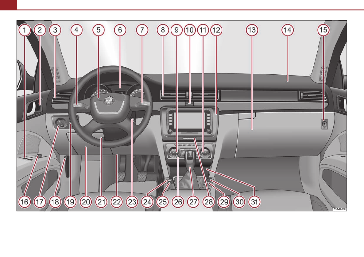
Fig. 1 Certain items of equipment shown in the illustration are only fitted to particular model versions or are optional items of equipment.
Page 10
Cockpit
A
A
A
A
A
A
A
A
A
A
A
A
A
A
A
A
A
A
A
A
A
A
A
A
A
A
A
A
A
A
A
Cockpit 9
Overview
This overview will help you to quickly familiarise yourself with the
displays and the control elements.
1
Power windows . . . . . . . . . . . . . . . . . . . . . . . . . . . . . . . . . . . . . . . . . . . .
2
Central locking switch . . . . . . . . . . . . . . . . . . . . . . . . . . . . . . . . . . . . . .
3
Air outlet vents . . . . . . . . . . . . . . . . . . . . . . . . . . . . . . . . . . . . . . . . . . . . .
4
Lever for the multi-functional switch:
− Turn signal light, headlight and parking light, headlight flasher
− Cruise control system* . . . . . . . . . . . . . . . . . . . . . . . . . . . . . . . . . . .
5
Steering wheel:
− with horn
− with driver airbag . . . . . . . . . . . . . . . . . . . . . . . . . . . . . . . . . . . . . . . .
− with pushbuttons for radio, navigation system and mobile
phone* . . . . . . . . . . . . . . . . . . . . . . . . . . . . . . . . . . . . . . . . . . . . . . . . .
6
Instrument cluster: Instruments and indicator lights . . . . . . . . . . .
7
Lever for the multi-functional switch:
− Multi-functional indicator* . . . . . . . . . . . . . . . . . . . . . . . . . . . . . . .
− Windshield wiper and wash system . . . . . . . . . . . . . . . . . . . . . . .
8
Air outlet vents . . . . . . . . . . . . . . . . . . . . . . . . . . . . . . . . . . . . . . . . . . . . .
9
Control dial for heating on the driver's seat* . . . . . . . . . . . . . . . . . .
10
Switch for hazard warning lights . . . . . . . . . . . . . . . . . . . . . . . . . . . . .
11
Control dial for heating on the front passenger seat* . . . . . . . . . .
12
Depending on equipment fitted:
− Radio*
− Navigation*
13
Storage compartment on the front passenger side . . . . . . . . . . . .
14
Front passenger airbag . . . . . . . . . . . . . . . . . . . . . . . . . . . . . . . . . . . . .
15
Switch for the front passenger airbag* (in front passenger storage
compartment) . . . . . . . . . . . . . . . . . . . . . . . . . . . . . . . . . . . . . . . . . . . . .
105
128
176
138
105
176
183
16
Electric exterior mirror adjustment . . . . . . . . . . . . . . . . . . . . . . . . . .
17
Light switch . . . . . . . . . . . . . . . . . . . . . . . . . . . . . . . . . . . . . . . . . . . . . . . .
18
Bonnet release lever . . . . . . . . . . . . . . . . . . . . . . . . . . . . . . . . . . . . . . .
19
Control dial for the instrument lighting and control dial for the head-
54
46
67
17
21
73
85
66
85
96
light beam range regulation* . . . . . . . . . . . . . . . . . . . . . . . . . . . . . . . .
20
Storage compartment on the driver's side . . . . . . . . . . . . . . . . . . . .
21
Lever for adjusting the steering wheel . . . . . . . . . . . . . . . . . . . . . . .
22
Driver's knee airbag* . . . . . . . . . . . . . . . . . . . . . . . . . . . . . . . . . . . . . . .
23
Ignition lock . . . . . . . . . . . . . . . . . . . . . . . . . . . . . . . . . . . . . . . . . . . . . . .
24
Depending on equipment fitted:
− Switch for the ESP* . . . . . . . . . . . . . . . . . . . . . . . . . . . . . . . . . . . . . .
− Switch for TCS . . . . . . . . . . . . . . . . . . . . . . . . . . . . . . . . . . . . . . . . . . .
25
Tyre inflation pressure-control system* . . . . . . . . . . . . . . . . . . . . . .
26
Depending on equipment fitted:
− Operating controls for Climatic . . . . . . . . . . . . . . . . . . . . . . . . . . .
− Operating controls for Climatronic* . . . . . . . . . . . . . . . . . . . . . . .
27
Depending on equipment fitted:
− Gearshift lever (manual gearbox) . . . . . . . . . . . . . . . . . . . . . . . . .
− Selector lever (automatic DSG)* . . . . . . . . . . . . . . . . . . . . . . . . . .
28
Indicator light for a switched off front seat passenger airbag* . .
29
Park Assist* . . . . . . . . . . . . . . . . . . . . . . . . . . . . . . . . . . . . . . . . . . . . . . . .
30
Front and rear parking aid* . . . . . . . . . . . . . . . . . . . . . . . . . . . . . . . . .
31
Depending on equipment fitted:
− Front ashtray* . . . . . . . . . . . . . . . . . . . . . . . . . . . . . . . . . . . . . . . . . . .
− Storage compartment* . . . . . . . . . . . . . . . . . . . . . . . . . . . . . . . . . .
Note
• Equipment which is marked * is only standard on certain vehicle model
versions or only suppliable as optional equipment for certain models.
76
60
222
65, 66
97
117
178
118
193
195
199
106
109
120
131
183
124
123
93
97
Using the system Safety Driving Tips General Maintenance Breakdown assistance Technical Data
Page 11

Cockpit10
• Cars with factory-fitted radio or navigation system are supplied with separate
instructions for operating such equipment.
• The arrangement of the controls and switches and the location of some items
on right-hand drive models may differ from that shown in ⇒ page 8, fig. 1. The
symbols on the controls and switches are the same as for left-hand drive models.
Page 12
The brief instruction
A1A2A3A
The brief instruction 11
Basic functions and important information
Introduction
The chapter of the brief instruction is only used as a quick reference
of the most important operating elements of the vehicle. It is necessary to observe all the information which is contained in the
following chapters of the Owner's Manual.
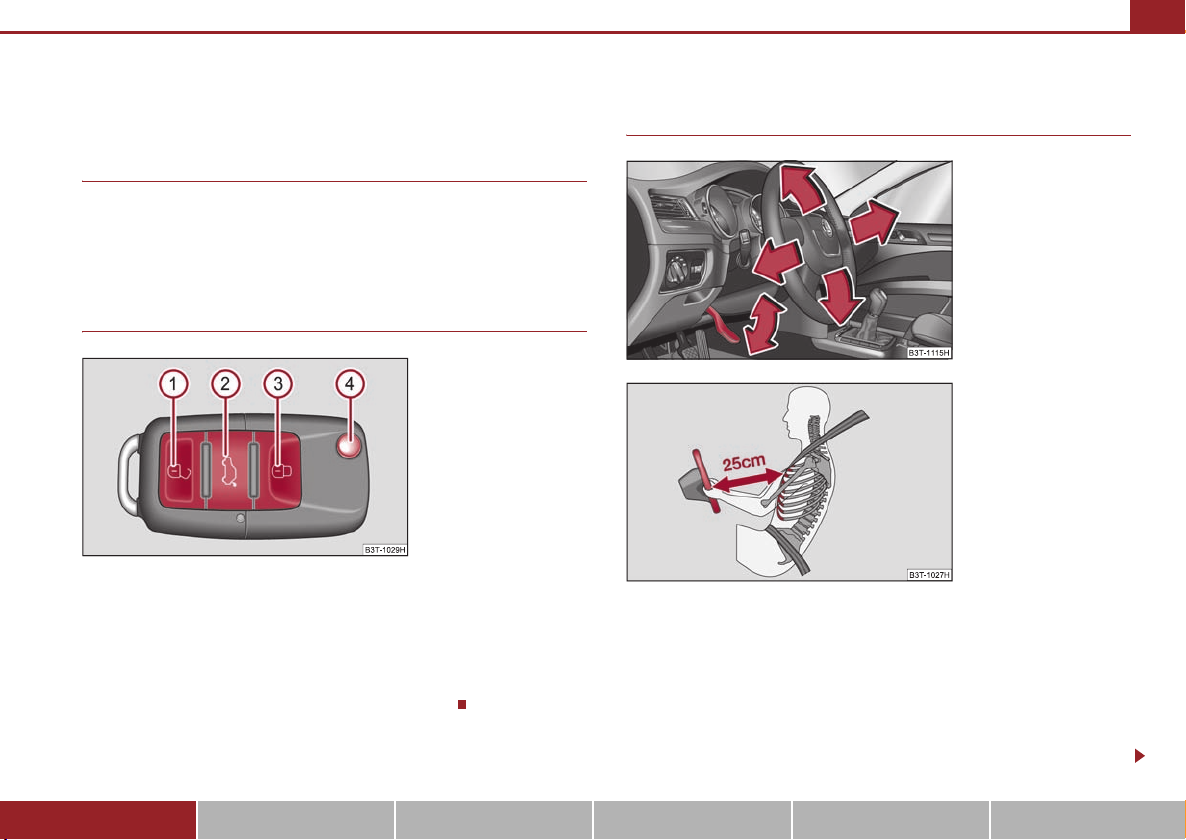
Unlocking and locking the vehicle
Fig. 2 Radio-operated key
Unlocking the vehicle
Unlocking the boot lid
Locking the vehicle
4
Folding out/folding up of the key
Further information ⇒ page 51, “Unlocking and locking car”.
Setting steering wheel position
Fig. 3 Adjustable steering
wheel: Lever next to the
steering column
Fig. 4 The correct distance of
the driver from the steering
wheel
You can set the height and the forward/back position of the steering
wheel to the desired position.
– Pull the lever below the steering column ⇒ fig. 3 down.
– Set the steering wheel to the desired position (concerning height and
forward/back position).
– Push the lever upwards as far as the stop.
Using the system Safety Driving Tips General Maintenance Breakdown assistance Technical Data
Page 13
The brief instruction12
A1A2A3A
Further information ⇒ page 117, “Setting steering wheel position”.
WARNING
• Adjust the steering wheel so that the distance between the steering
wheel and your chest is at least 25 cm ⇒ page 11, fig. 4. Not maintainin g this
minimum distance will mean that the airbag syste m will not b e abl e to pro perly protect you - hazard!
• You must not adjust the steering wheel when the vehicle is moving!
• Fo r sa fet y re aso ns t he l ev er m ust alw ays be fir mly pus hed up t o a voi d th e
steering wheel altering its position unintentionally when driving - risk of
accident!
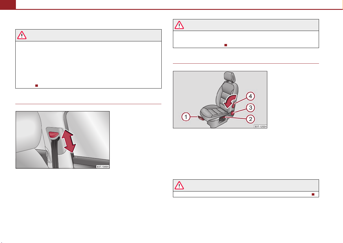
Seat belt height adjuster
Fig. 5 Front seat: Seat belt
height adjuster
– Move the height adjuster in the desired direction up or down ⇒ fig. 5.
– Then pull firmly on the belt to ensure that the seat belt height adjuster
has correctly locked in place.
WARNING
Adjust the height of the belt in such a way that the shoulder part of the belt
is positioned approximately across the middle of your shoulder - on no
account across your neck!
Adjusting the front seats
Fig. 6 Controls at seat
Adjusting a seat in a forward/back direction
Adjusting height of seat
Adjust the angle of the seat backrest
4
Adjusting lumbar support
Further information ⇒ page 78, “Adjusting the front seats”.
WARNING
Only adjust the driver seat when the vehicle is stationary - risk of injury!
Further information ⇒ page 171, “Seat belt height adjuster”.
Page 14
The brief instruction 13
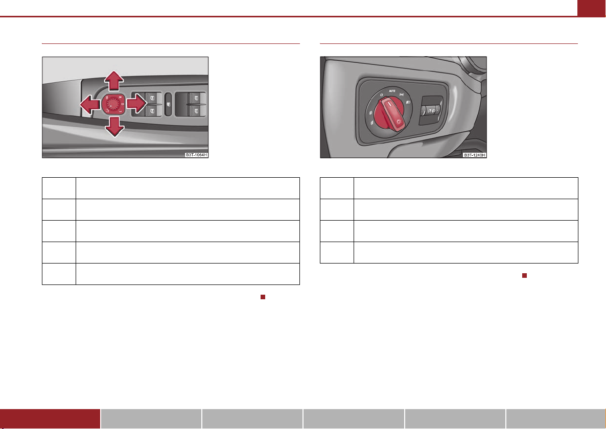
Electric exterior mirror adjustment
Fig. 7 Inner part of door:
Rotary knob
Heating of the external mirror
Adjusting left and right exterior mirrors simultaneously
Adjusting the right-hand exterior mirror
Switching off operating control
Folding in both exterior mirrors*
Further information ⇒ page 13, “Electric exterior mirror adjustment”.
Switching lights on and off
Fig. 8 Dash panel: Light
switch
Further information ⇒ page 60, “Switching lights on and off ”.
Automatic light control*, Adaptive headlights (AHL)*
Switching off all lights/daylight driving lights*
Switching on side lights
Switching on the low beam and main beam
Using the system Safety Driving Tips General Maintenance Breakdown assistance Technical Data
Page 15

The brief instruction14
AAABACA
AAA0A1A2A3A4A
AAABACADA
Turn signal and main beam lever
Fig. 9 Turn signal and main
beam lever
B3T-1241H
Turn signal light right
Turn signal light left
Switching over between low beam and main beam lights
D
Headlight flasher
Further information ⇒ page 67, “The turn signal and main beam lever ”.
Windscreen wiper lever
Fig. 10 Windscreen wiper
lever
Intermittent switch, sensitivity setting rain sensor*
Wipers off
Intermittent wipe
Slow wipe
Fast wipe
one time wipe
5
Automatic wipe/wash
Further information ⇒ page 73, “Windshield wiper and wash system”.
Power windows
Fig. 11 Buttons on the
driver's door
Button for the power window in the driver's door
Button for the power window in the front passenger's door
Button for the power window at the rear right door
Button for the power window at the rear left door
S
Safety switch
Further information ⇒ page 54, “Power windows”.
Page 16
The brief instruction 15
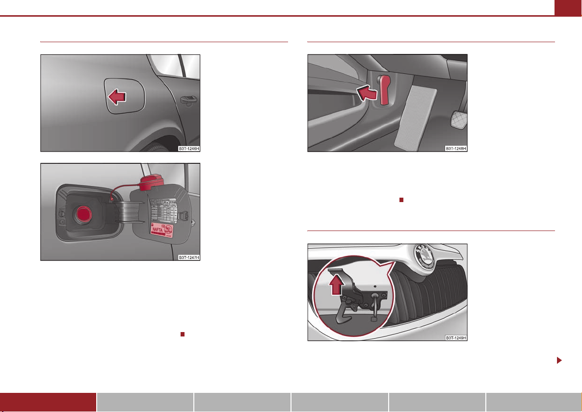
Refuelling
Fig. 12 Right rear side of the
vehicle:Open fuel filler flap
Fig. 13 Fuel filler flap with
cap unscrewed
– In order to open the fuel filler flap, press it on the left side in the middle
⇒ fig. 12.
– Unscrew the fuel filler cap anti-clockwise and place the fuel filler cap
from above on the fuel filler flap ⇒ fig. 13.
Further information ⇒ page 220, “Refuelling”.
Bonnet remote release
Fig. 14 Bonnet release lever
– Pull the unlocking lever below the dash panel on the driver's side
⇒ fig. 14.
Further information ⇒ fig. 14.
Opening the bonnet
Fig. 15 Radiator grille: Lever
of the locking button
– Press the locking button ⇒ fig. 15, the bonnet is then unlocked.
Using the system Safety Driving Tips General Maintenance Breakdown assistance Technical Data
Page 17
The brief instruction16
AAABA
– Grasp the bonnet at the bottom part of the radiator grille and lift it
towards the top so that it is held opened by the gas pressure support.
Further information ⇒ page 222, “Opening and closing the bonnet.”.
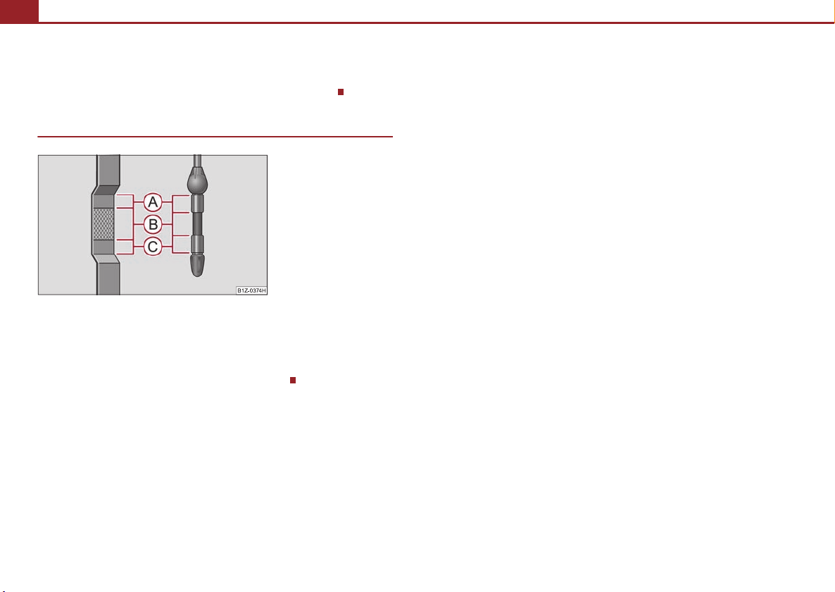
Inspecting the engine oil level
Fig. 16 Dipstick
Engine oil must not be refilled.
Engine oil can be refilled.
C
Engine oil must be refilled.
Further information ⇒ page 224, “Check engine oil level”.
Page 18
Instruments and Indicator/Warning Lights
A1A
A3A
A5A
A
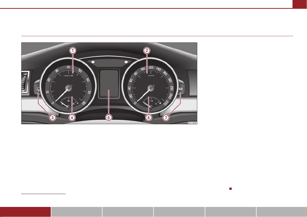
General view of the instrument cluster
Instruments and Indicator/Warning Lights 17
Fig. 17 Instrument cluster
Engine revolutions counter ⇒ page 18
2
Speedometer ⇒ page 18
Button for display mode:
− Set hours / minutes
− Activating / deactivating the second speed in mph or km/h*
− Service interval - Display of the remaining number of days or miles to the
next Inspection Service / Reset*
4
Coolant temperature gauge ⇒ page 18
Display:
− with counter for distance driven ⇒ page 19
1)
Valid for countries where the values are indicated in British measuring units.
Using the system Safety Driving Tips General Maintenance Breakdown assistance Technical Data
1)
− with Service Interval Display ⇒ page 20
− with digital clock ⇒ page 21
− with Multi-functional indicator* ⇒ page 21
− with Information display* ⇒ page 26
6
Fuel gauge ⇒ page 18
7
Button for:
− Reset trip counter for distance driven
− Resetting Service Interval Display
− Set hours / minutes
− Activate / deactivate display mode
Page 19
Instruments and Indicator/Warning Lights18
A
A4A
Engine revolutions counter
The red zone of the rev counter scale ⇒ page 17, fig. 17 indicates the range in
which the engine control unit begins to limit the engine speed. The engine control
unit restricts the engine speed to the steady limit value.
Shift into the next higher gear or select the selector lever position D of the automatic gearbox before reaching the red zone of the rev counter scale.
Avoid high engine speeds during the driving time and before the engine has been
warmed up to operating temperature ⇒ page 201.
For the sake of the environment
Shifting up early helps you save fuel and reduce the operating noise of your
vehicle.
1
Speedometer
Warning against excessive speeds*
An acoustic warning signal will sound when the vehicle speed exceeds 120 kilometres per hour. The acoustic warning signal will switch off again when the vehicle
speed goes below this speed limit.
Note
This function is only valid for some countries.
Coolant temperature gauge
The coolant temperature gauge ⇒ page 17, fig. 17 operates only when the ignition is switched on.
In order to avoid any damage to the engine, please pay attention to the following
notes regarding the temperature ranges:
Cold range
If the pointer is in the left-hand area of the scale it means that the engine has not
yet reached its operating temperature. Avoid running at high engine speeds, at full
throttle and at severe engine loads.
The operating range
The engine has reached its operating temperature as soon as the pointer moves
into the mid-range of the scale. The pointer may also move further to the right at
high engine loads and high outside temperatures. This is not critical provided the
warning symbol in the instrument cluster does not flash.
If the symbol in the instrument cluster flashes it means that either the coolant
temperature is too high or the coolant level is too low. Observe the guidelines
⇒ page 38, “Coolant temperature/ Coolant quantity ”.
WARNING
Pay attention to the warning notes ⇒ page 223, “Working in the engine
compartment” before opening the bonnet and inspecting the coolant level.
Caution
Additional headlights and other attached components in front of the fresh air inlet
impair the cooling efficiency of the coolant. There is then a risk of the engine overheating at high outside temperatures and high engine loads!
Fuel gauge
The fuel gauge ⇒ page 17, fig. 17 only operates when the ignition is switched
on.
The fuel tank has a capacity of about 60 litres. The warning symbol in the instrument cluster lights up when the pointer reaches the reserve marking. There are now
about 9 litres of fuel remaining in the tank. This symbol is a reminder for you, that
you must refuel.
6
Page 20
Instruments and Indicator/Warning Lights 19
A
The following will be displayed in the information display*:
Please refuel!
An audible signal sounds as an additional warning signal.
Caution
Never run the fuel tank completely empty! An irregular supply of fuel can lead to
irregular engine running. Unburnt fuel may get into the exhaust system and
damage the catalytic converter.
Note
After filling up, it can occur that during dynamic driving (e.g. numerous curves,
braking, driving downhill and climbing a steep hill) the fuel gauge indicates approx.
a fraction less. When stopping or during less dynamic driving, the correct fuel
supply quantity is indicated. This effect is not a fault.
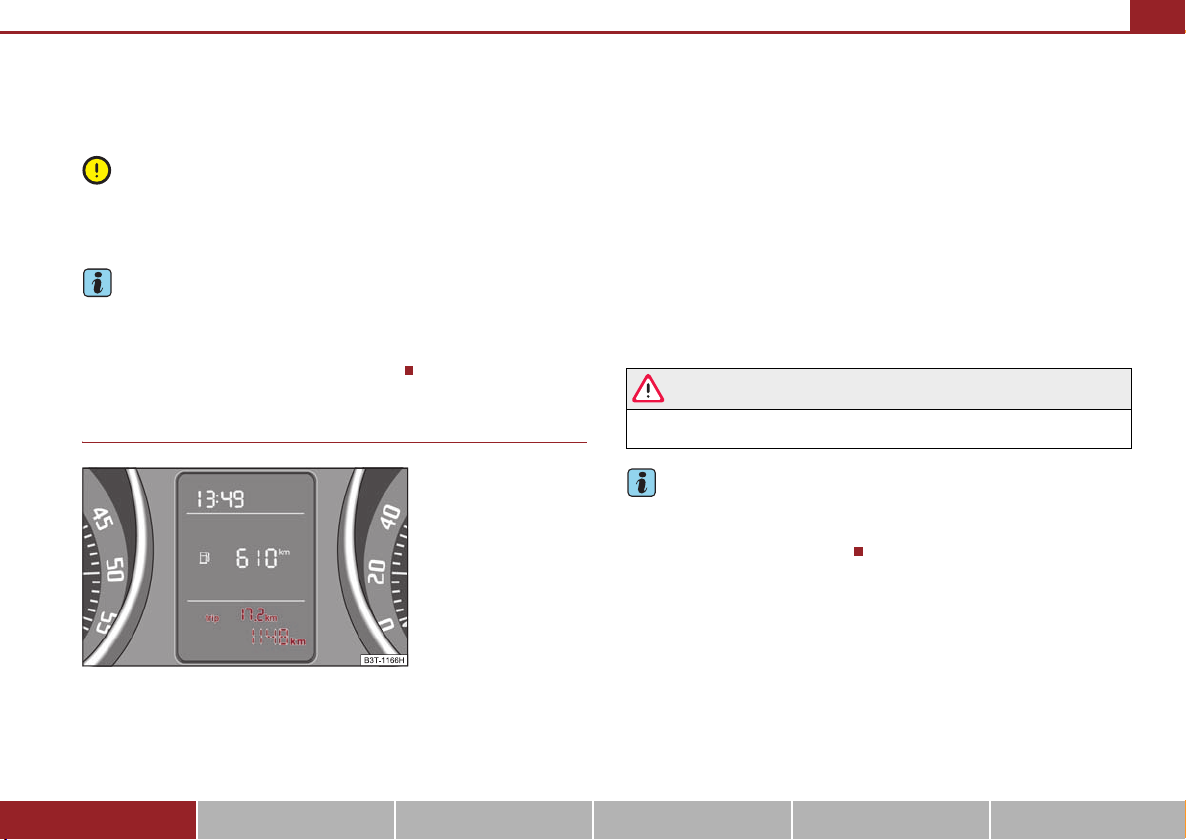
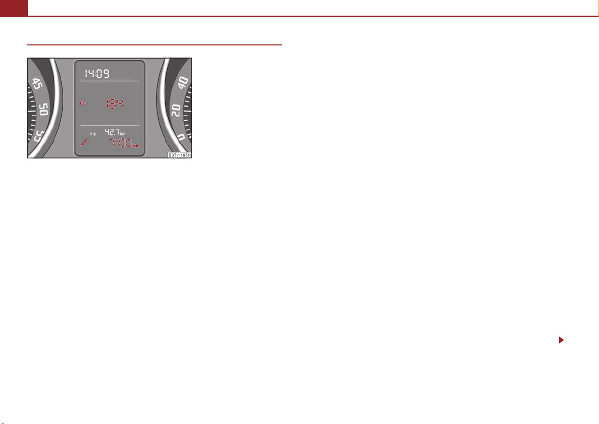
Counter for distance driven
Fig. 18 Display: Counter for
distance driven
Reset button
If you hold the reset button ⇒ page 17 pressed for about 1 second, the trip
counter is set back to zero.
Trip counter for distance driven
The trip counter indicates the distance which you have driven ⇒ fig. 18 since this
counter was last reset - in steps of 100 metres or 1/10 of a mile.
Counter for distance driven
The counter for distance driven ⇒ fig. 18 indicates the total distance in kilometers
or miles which the vehicle has driven.
Fault disp lay
If there is a fault in the instrument cluster, a constant text will appear in the display
Error. Have the fault rectified as soon as possible by a specialist workshop.
7
WARNING
Never seek to adjust the trip counter for distance driven while driving for
safety reasons!
Note
If vehicles which are fitted with the information display* the display of the second
speed is activated in mph or km/h, this driving speed is indicated instead of the
counter for the total distance driven.
The distance which you have driven with your vehicle is shown in kilometres (km).
In some countries the measuring unit “mile” is used.
Using the system Safety Driving Tips General Maintenance Breakdown assistance Technical Data
Page 21
Instruments and Indicator/Warning Lights20
A3A
Service Interval Display
Fig. 19 Service Interval
Display: Note
Depending on the equipment installed in the vehicle, the text can differ on the
display.
Service Interval Display
Before the next service interval a key symbol and the remaining kilometers are
indicated after switching on the ignition ⇒ fig. 19. At the same time, a display
appears regarding the remaining days until the next service interval.
The following will be displayed in the information display*:
Service in ... km or... days
The kilometre indicator or the days indicator reduces in steps of 100 km. or days
until the service due date is reached.
A flashing key symbol and the text Service appears in the display for 20 seconds
as soon as the due date for the service is reached.
The following will be displayed in the information display*:
Service now!
Display regarding the distance and days until the following service interval
You can use the button to display the remaining distance driven and the days
until the next service interval ⇒ page 17.
A key symbol and a display regarding the remaining kilometers appear for 10
second in the display. At the same time, a display appears regarding the remaining
days until the next service interval.
On vehicles which are equipped with information display*, you can call up this
information in the following menu on ⇒ page 27:
SETUP (Settings)
Service Interval (Service)
Info
The following will be displayed in the information display* for 10 seconds:
Service in ... km or... days
Resetting Service Interval Display
It is only possible to reset the Service Interval Display, if a service message or at least
a pre-warning is shown on the display of the instrument cluster.
We recommend having this resetting performed by a specialist garage.
The specialist garage:
• resets the memory of the display after the appropriate inspection,
• makes an entry in the Service schedule,
• affix the sticker with the entry of the following service interval to the side of the
dash panel on the driver's side.
Reset the service interval displays by using the reset button ⇒ page 17 on the
trip counter.
On vehicles which are equipped with information display*, you can call up this
information in the following menu on ⇒ page 27:
SETTINGS (SETTINGS)
Service Interval (Service)
Reset
7
Page 22
Instruments and Indicator/Warning Lights 21
A3A7A3A
Caution
We recommend that you do not reset the Service Interval Display yourself otherwise this can result in the service interval display being incorrectly set, which may
also result in problems with operation of your vehicle.
Note
• Never reset the display between service intervals otherwise this may result in
incorrect readouts.
• information is retained in the Service Interval Display also after the battery of
the vehicle is disconnected.
• If the instrument cluster is exchanged after a repair, the correct values must be
entered in the counter for the Service Interval Display. This work is carried out by a
specialist garage.
• The data displayed is the same after resetting the display with flexible service
intervals (QG1) using the reset button as that for a vehicle with fixed service intervals (QG2). We therefore recommend having the Service Interval Display reset only
by an authorised Škoda Service Partner who is familiar with the procedure for resetting the display with a vehicle system tester.
• Please refer to the brochure Service schedule for extensive information about
the service intervals.
Digital clock
The time is set with the buttons and ⇒ page 17, fig. 17.
Select the display which you wish to change with the button and carry out the
change with the button .
On vehicles which are fitted out with the information display*, it is possible to set
the time in the menu Time ⇒ page 30.
7
WARNING
The clock should not be adjusted while driving for safety reasons but only
when the vehicle is stationary!
Multi-functional indicator (onboard computer)*
Introduction
The multi-functional indicator appears in the display ⇒ page 22, fig. 20 or in the
information display ⇒ page 26 depending on the equipment fitted to your vehicle.
The multi-functional indicator offers you a range of useful information.
The outside temperature ⇒ page 24
Driving time ⇒ page 24
Current fuel consumption ⇒ page 24
Average fuel consumption ⇒ page 24
Range ⇒ page 25
Distance driven ⇒ page 25
Average speed ⇒ page 25
Current speed* ⇒ page 25
Warning against excessive speeds* ⇒ page 25
On vehicles which are fitted out with information display*, it is possible to switch
off the display of some information.
Caution
Pull out the ignition key while having contact with the display (for example when
cleaning) in order to prevent any damage.
Using the system Safety Driving Tips General Maintenance Breakdown assistance Technical Data
Page 23
Instruments and Indicator/Warning Lights22
ABA
AAA
Note
• In certain national versions the displays appear in the Imperial system of meas-
ures.
• If the display of the second speed is activated in mph, the current speed* is not
indicated in km/h on the display.
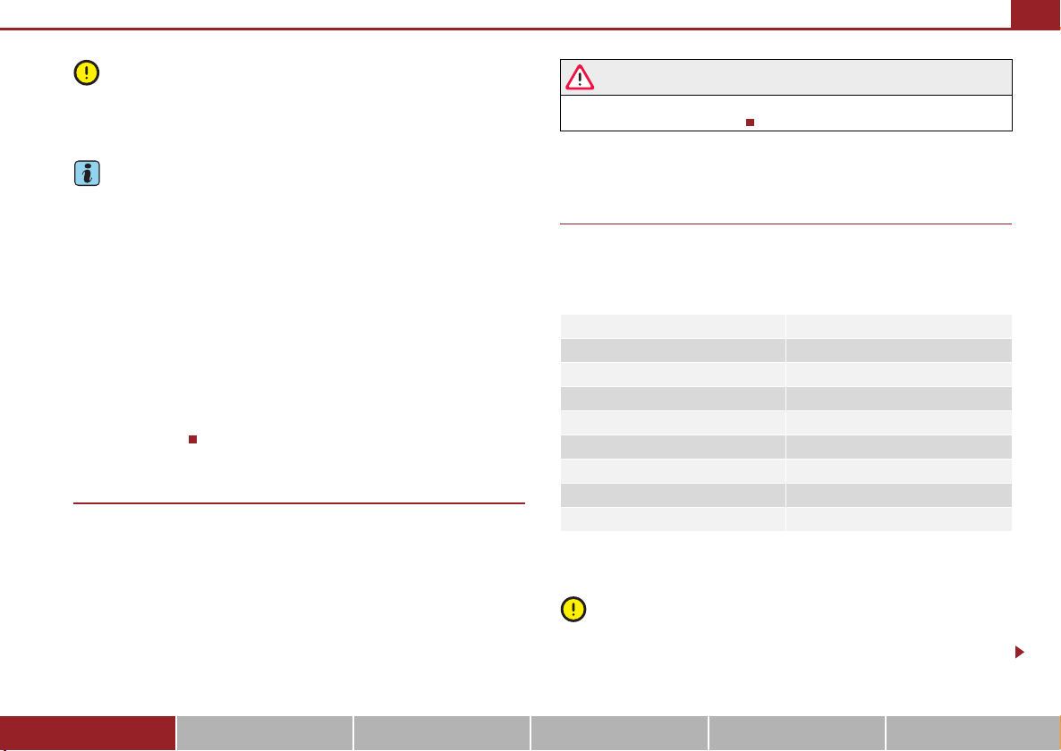
Memory
Fig. 20 Multi-functional
indicator
The multi-functional indicator is equipped with two automatic memories. The
selected memory is displayed in the middle of the display field ⇒ fig. 20.
The data of the single-trip memory (memory 1) is shown if a 1 appears in the
display. A 2 shown in the display means that data relates to the total distance
memory (memory 2).
Switching over the memory with the help of the button ⇒ fig. 21 on the windscreen wiper lever or with the help of the button on the multifunction steering
wheel* ⇒ page 23.
Single-trip memory (memory 1)
The single-trip memory collates the driving information from the moment the ignition is switched on until it is switched off. New data will also flow into the calculation of the current driving information if the trip is continued within 2 hours after
D
switching off the ignition. The memory will be is automatically erased, on the other
hand, if the trip is interrupted for more than 2 hours.
Total-trip memory (memory 2)
The total distance driven memory gathers data from any number of individual journeys up to a total of 99 hours and 59 minutes driving or 9.999 kilometres driven.
The memory is deleted when either of these limits is reached and the calculation
starts from anew.
The total-trip memory will not, contrary to the single-trip memory, be deleted after
a period of interruption of driving of 2 hours.
Note
All information in the memory 1 and 2 is erased if the battery of the vehicle is
disconnected.
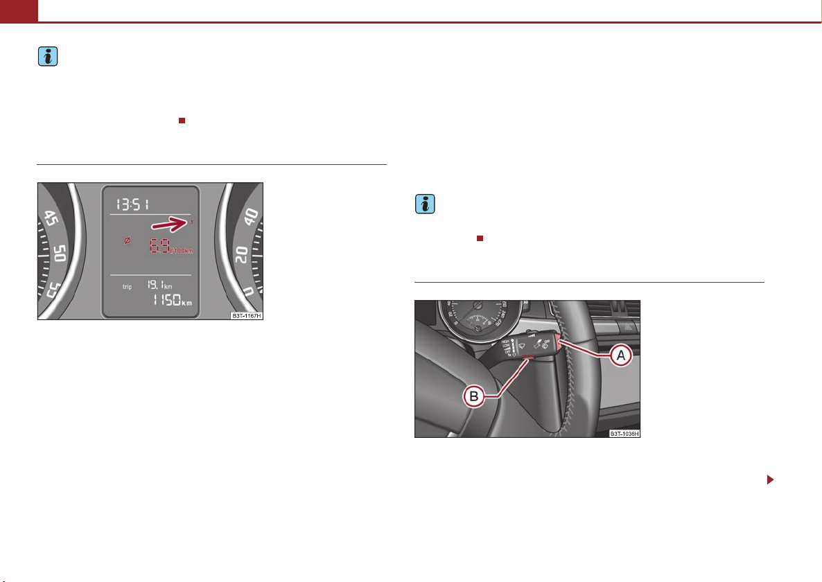
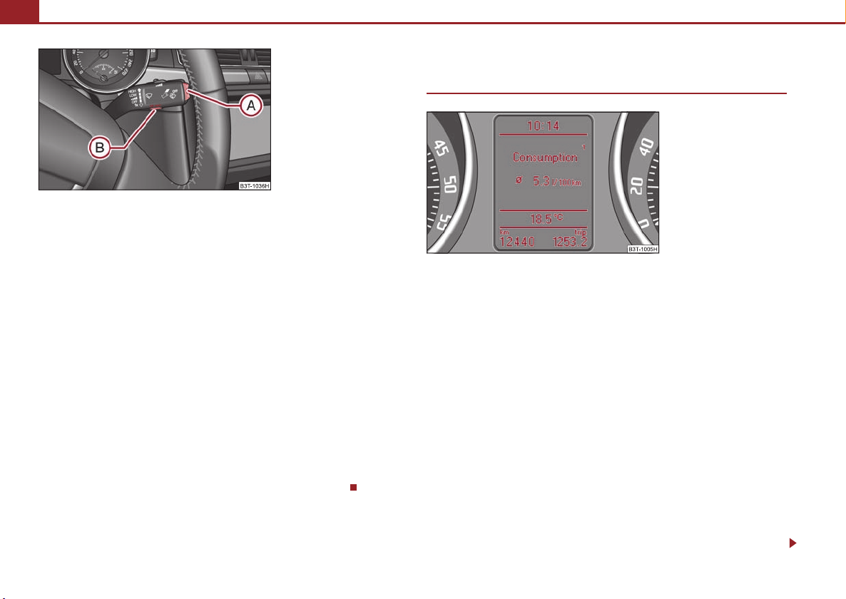
Operating with the buttons on the windshield wiper lever
Fig. 21 Multi-functional
indicator: Control elements
The rocker switch and the button are located in the grip of the
B
window wiper lever ⇒ fig. 21.
Page 24

Instruments and Indicator/Warning Lights 23
ABA
A
A
AAA
ADADA
ADA
A
Selecting the memory
– Short-term pressing of the button allows to select the desired
memory.
Selecting the functions
– Press the top or bottom rocker switch for longer than 0.5 seconds.
A
In this way, call up in sequence the individual functions of the multifunctional indicator.
Setting function to zero
– Select the memory you want.
– Press button for more than 1 second.
The following readouts of the selected memory will be set to zero by button :
B
B
• average fuel consumption,
• distance driven,
• average speed,
• Driving time.
You can only operate the multi-functional indicator when the ignition is switched
on. After the ignition is switched on, the function displayed is the one which you last
selected before switching off the ignition.
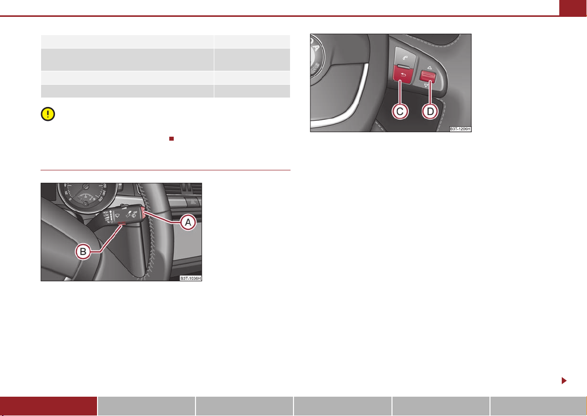
On vehicles fitted with the multifunction steering wheel*, the buttons and
have been replaced with the rotary control on the multifunction steering wheel
⇒ fig. 22.
B
Operating with the buttons on the multifunction steering wheel*
Fig. 22 Multi-functional
indicator: Operating with the
buttons on the multifunction
steering wheel
Switching over and resetting is performed with the handwheel
⇒ fig. 22.
Selecting the memory
– Short-term pressing of the button allows to select the desired
memory.
Selecting the functions
– By pressing the button , you can call up the menu of the multi-func-
C
tional indicator.
– Turn the handwheel upwards or downwards. In this way, call up in
sequence the individual functions of the multi-functional indicator.
– Short-term pressing of the button allows to select the highlighted
D
function.
Setting function to zero
– Select the memory you want.
– Press the button for more than 1 second.
Using the system Safety Driving Tips General Maintenance Breakdown assistance Technical Data
D
Page 25
Instruments and Indicator/Warning Lights24
A
AAACABA
The following readouts of the selected memory will be set to zero with the button
D
:
• average fuel consumption,
• distance driven,
• average speed,
• Driving time.
You can only operate the multi-functional indicator when the ignition is switched
on. After the ignition is switched on, the function displayed is the one which you last
selected before switching off the ignition.
Outside temperature
Fig. 23 The outside temperature
The outside temperature appears in the display when the ignition is switched on.
If the outside temperature drops below +4 °C, a snow flake symbol (warning signal
for ice on the road) appears before the temperature indicator ⇒ fig. 23 and a
warning signal sounds. After pressing the rocker switch at the windshield wiper
lever ⇒ page 22, fig. 21 or the button at the multifunction steering wheel
⇒ page 23, fig. 22, the function shown last is indicated.
WARNING
Do not only rely upon the information given on the outside temperature
display that there is no ice on the road. Please note that black ice may also be
present on the road surface even at temperatures around +4 °C - warning,
drive with care!
Driving time
The driving time which has elapsed since the memory was last erased, appears in
the display. If you wish to measure the driving time as of a particular time, you must
set the memory to zero at this moment in time by pressing the button on the
windshield wiper lever ⇒ page 22, fig. 21 or the handwheel on the multifunction steering wheel* ⇒ page 23, fig. 22 for longer than 1 second.
The maximum distance indicated in both memories is 99 hours and 59 minutes.
The indicator is set back to null if this period is exceeded.
D
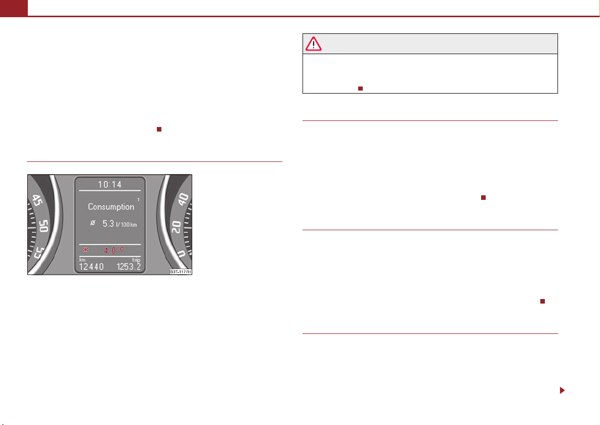
Current consumption
The current fuel consumption level is shown in the display in litres/100 km. This
information can help you to adapt your style of driving to the fuel consumption you
wish to achieve.
The display appears in litres/hour if the vehicle is stationary or driving at a low
speed.
The indicated value will be updated every 0,5 seconds while you are driving.
Average fuel consumption
The average fuel consumption since the memory was last erased is shown in the
display in litres/100 km ⇒ page 22. This information can help you to adapt your
style of driving to the fuel consumption you wish to achieve.
If yo u wi sh to d et erm in e t he a ve rag e fu el co nsu mp tio n o ver a c er tai n p er iod of tim e
you must set the memory to zero at the start of the measurement using the button
Page 26
Instruments and Indicator/Warning Lights 25
ABA
A
ADA
A
A
on the windshield wiper lever ⇒ page 22, fig. 21 or with the handwheel on
the multifunction steering wheel* ⇒ page 23, fig. 22. A zero appears in the display
for the first 100 m you drive after erasing the memory.
The indicated value will be updated every 5 seconds while you are driving.
D
Note
The amount of fuel consumed will not be indicated.
Range
The estimated range in kilometres is shown on the display. It indicates the distance
you can still drive with your vehicle based on t he present level of fuel in the tank for
the same style of driving.
The readout is shown in steps of 10 km. After lighting up of the indicator light for the
fuel reserve the display is shown in steps of 5 km.
The fuel consumption for the last 50 km is taken as a basis for calculating the range.
If you drive in a more economical manner from this moment on, the range will be
increased accordingly.
If the memory is set to zero (after disconnecting the battery), the fuel consumption
of 10 ltr./100 km is calculated for the range; afterwards the value is adapted accordingly to the style of driving.
Distance driven
The distance driven since the memory was last erased appears in the display
⇒ page 22. If you wish to measure the distance driven of a particular time, you
must set the memory to zero at this moment in time by pressing the button on
the windshield wiper lever ⇒ page 22, fig. 21 or the handwheel on the multifunction steering wheel* ⇒ page 23, fig. 22.
The maximum distance indicated in both switch positions is 9 999 km. The indicator
is set back to null if this period is exceeded.
B
Average speed
The average speed since the memory was last erased is shown in the display in
km/hour ⇒ page 22. If you wish to determine the average vehicle speed over a
certain period of time you must set the memory to zero at the start of the measurement using the button on the windshield wiper lever ⇒ page 22, fig. 21 or with
the handwheel on the multifunction steering wheel* ⇒ page 23, fig. 22.
A zero appears in the display for the first 100 m you drive after erasing the memory.
The indicated value will be updated every 5 seconds while you are driving.
B
D
Current speed*
The current speed which is identical to the display of the speedometer, is indicated
on the display ⇒ page 17, fig. 17.
2
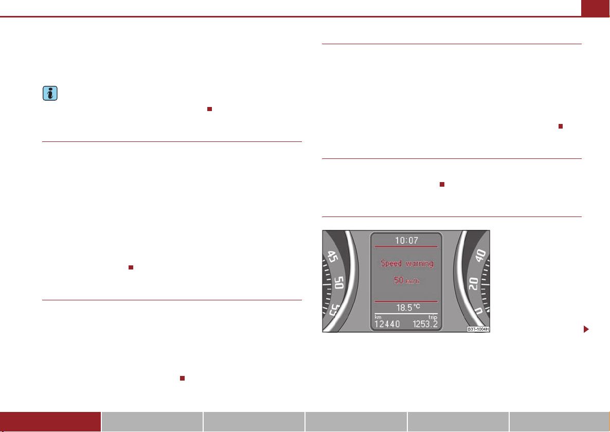
Warning against excessive speeds
Fig. 24 Speed setting
Using the system Safety Driving Tips General Maintenance Breakdown assistance Technical Data
Page 27
Instruments and Indicator/Warning Lights26
A
ADA
A
Fig. 25 Multi-functional
indicator: Control elements
Warning against excessive speeds
This function enables you to set a speed limit, e.g. if you drive in town. A text in the
display is intended to draw your attention to the fact that you have exceeded the set
speed limit.
You can set the desired speed limit as follows:
• Select the menu point Speed warning --- km/h (warning at --- km/h)..
• Drive e.°g at a speed of 50 km/h.
• Press the button on the windshield wiper lever ⇒ fig. 25 or the handwheel
on the multifunction steering wheel* ⇒ page 23, fig. 22. Speed warning
50 km/h (warning at 50 km/h) is displayed in the information display*
⇒ page 25, fig. 24.
If you now exceed the set speed limit, Speed 50°km/h exceeded will be shown on
the display. This message is indicated for as long as the speed is reduced below the
set limit or switch off the message by pressing the button on the windshield
wiper lever ⇒ fig. 25 or the handwheel on the multifunction steering wheel*
⇒ page 23, fig. 22.
An audible signal sounds as an additional warning signal.
The set speed limit remains stored even after switching off the ignition.
B
B
D
Information display*
Introduction
Fig. 26 Instrument cluster:
Information display
The information display provides you with information in a convenient way
concerning the current operating state of your vehicle. The information system
also provides you with data (depending on the equipment installed in the vehicle)
relating to the radio, mobile phone, multi-functional indicator, navigation system
and automatic gearbox.
Certain functions and operating conditions are always being checked on the
vehicle when the ignition is switched on and also while driving.
Functional faults, if required repair work and other information are indicated by red
symbols ⇒ page 29 and yellow symbols ⇒ page 30.
Lighting up of certain symbols is combined with an acoustic warning signal.
Information and texts giving warnings are also shown in the display ⇒ page 33.
The display of text is possible in the following languages:
Czech, English, German, French, Italian, Spanish, Portuguese, Russian and
Chinese.
You can select the desired language in the setting menu.
The following information can be shown in the display (depending on the equipment installed on the vehicle):
Page 28
Main menu ⇒ page 27
A
AAABACADA
ACA
Door, luggage compartment door and bonnet ajar
warning
Service Interval Display ⇒ page 20
Selector lever positions for the automatic gearbox DSG ⇒ page 131
⇒ page 28
Instruments and Indicator/Warning Lights 27
Caution
Pull out the ignition key while having contact with the display (for example when
cleaning) in order to prevent any damage.
Main menu
Fig. 27 Information display:
Controls on the windshield
wiper lever
Fig. 28 Information display:
Controls on the multifunction steering wheel
Operating with the buttons on the windshield wiper lever
– You can activate the MAIN MENU by pressing the rocker switch
A
⇒ fig. 27 for more than 1 second.
– You can select the menu through the rocker switch . When the
pushbutton is briefly pressed, the information you have selected is
displayed.
Operating with the buttons on the multifunction steering wheel
– You can activate the MAIN MENU by pressing the rocker switch
⇒ fig. 28 for more than 1 second.
– You can select the individual menus by pressing the handwheel .
After briefly pressing the handwheel , the desired menu is indi-
D
cated.
– After briefly pressing the button you can achieve a higher level, by
pressing the button for longer than 1 second, you can call up the
C
MAIN MENU.
You can select the following information (depending on the equipment installed on
the vehicle):
MFD (Onboard computer) ⇒ page 21
Audio*
Using the system Safety Driving Tips General Maintenance Breakdown assistance Technical Data
Page 29
Instruments and Indicator/Warning Lights28
A
A
Navigation*
Phone* ⇒ page 152
Aux. Heating (auxiliary heating)* ⇒ page 112
Assistant (Assistant)*
Vehicle status ⇒ page 29
Setup ⇒ page 30
The menu Audio is only displayed when the factory-fitted Radio* is switched on.
The menu Navigation is only displayed when the factory-fitted Navigation system*
is switched on.
The menu Aux. Heating is only then displayed, if the vehicle is fitted with auxiliary
heating*.
The menu Assistant is only then displayed, if the vehicle is fitted with cornering
lights*.
Note
• If warning messages are shown on the information display ⇒ page 28
⇒ page 29, these messages can be confirmed with the button on the wind-
shield wiper lever or with the button on the multifunction steering wheel in
D
order to call up the main menu.
B
• If you do not activate the information display at that moment, the menu shifts
to one level higher every 10 seconds.
• The operation of the radio* or the navigation system* is described in separate
operating instructions to be found in the on-board literature.
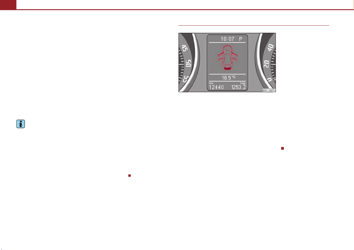
Door, luggage compartment door and bonnet ajar warning
Fig. 29 Information display:
Door warning
The door, luggage compartment and bonnet ajar warning lights up if at least one
door, the luggage compartment or bonnet are not closed. The symbol indicates
which door is still open or whether the luggage compartment door or bonnet is not
closed ⇒ fig. 29.
The symbol goes out as soon as the doors, luggage compartment door and bonnet
are completely closed.
A warning signal sounds if the car is driven at a speed of more than 6km/hour and
if the engine or the luggage compartment door is open.
Page 30

Instruments and Indicator/Warning Lights 29
Auto Check Control*
Car state
Fig. 30 Information display:
Display of operational fault
The Auto Check Control carries out a check of certain functions and vehicle components. The check is performed constantly when the ignition is switched on, both
when the vehicle is stationary, as well as when driving.
Some operational faults, urgent repairs, service work or other information appear
in the display of the instrument cluste r. The displays are shown with a red or yellow
light symbol depending on the priority of the message.
The red symbols indicate danger (priority 1) while the yellow symbols indicate a
warning (priortity 2). Information for the driver may also appear in addition to the
symbols ⇒ page 33.
Shown in the menu Vehicle status, if there is at least one error message. After
selecting this menu the first of the error messages is displayed. Several error
messages are shown on the display under the message e.°g. 1/3 ⇒ fig. 30. This
indicates that the first of a total of three error messages is displayed.The respective
messages are displayed one after the other in an interval of 5 seconds. Check as
soon as possible the displayed error messages.
As long as the operational faults are not rectified, the symbols are always indicated
again. After the first display, the symbols are indicated without information for the
driver.
If a fault occurs, a warning signal will also sound in addition to the symbol and text
in the display:
• Priority 1 - three warning signals
• Priority 2 - one warning signal
Red symbols
A red symbol signals danger.
Fig. 31 Information display:
Oil pressure is low
Proceed as follows if a red symbol is displayed:
– Stop the vehicle.
– Switch the engine off.
– Investigate the function indicated.
– Obtain professional assistance.
Meaning of the red symbols:
Three successive warning signals will sound if a red symbol appears.
Engine oil pressure too low ⇒ page 37
Using the system Safety Driving Tips General Maintenance Breakdown assistance Technical Data
Page 31
Instruments and Indicator/Warning Lights30
Yellow symbols
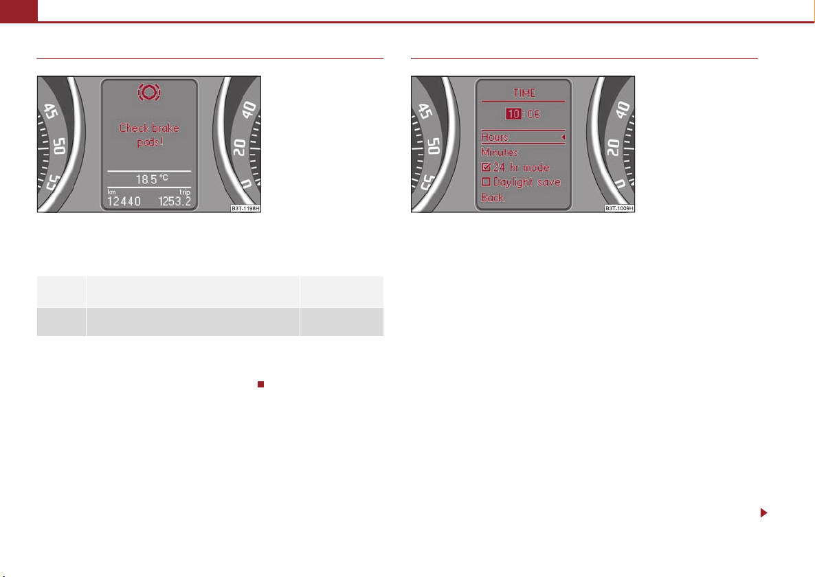
Fig. 32 Information display:
Brake pad worn
Check the relevant function as soon as possible.
The meaning of the yellow symbols:
Check engine oil level,
engine oil sensor faulty
Brake pad worn ⇒ page 40
One warning signal will sound if a yellow symbol appears.
If several operational faults of priority 2 exist, the symbols appear one after the
other and are each illuminated for about 5 seconds.
⇒ page 42
Set-up
Fig. 33 Setting the clock
You can change certain settings by means of the information display. The current
setting is shown on the information display in the respective menu at the top below
the line ⇒ fig. 33.
You can select the following information (depending on the equipment installed on
the vehicle):
• MFD Data (MFA DATA)
• Convenience
• Lights & Vision (Lights & Vision)
• Time
• Winter tyres
• Language
• Units
• Assistant (Assistant)
• Alt. speed dis.
• Trav el mod e
• Service Interval (Service)
• Factory Setting
• Back
Page 32

Instruments and Indicator/Warning Lights 31
After selecting the menu point Back you will reach one level higher in the menu.
Displays of the MFA
Here you can switch off or on certain displays of the multi-functional indicator.
Comfort*
You can set the following functions (depending on the equipment installed on the
vehicle):
On vehicles with rain sensor you can switch on or off the
function for automatic closing of the windows and the
Rain closing
sliding/tilting roof in case of rain and locked vehicle. If it
is not raining and the function is set, the windows
including the sliding/tilting roof are closed automatically
after approx. 12 hours.
Door open Here you can switch on or off the functions for opening
a single door and automatic closing.
ATA co nfirm
Here you can set if a signal tone should sound additionally when activating or deactivating the anti-theft alarm
system .
Window op. Here you can set the convenience mode only for the
driver window or for all the windows.
Mirror down
Here you can switch on or off the function for mirror
lowering on the front passenger side when engaging the
reverse gear.
Mirror adjust. Here you can switch on or off the function for left and
right exterior mirror adjustment simultaneously.
After selecting this menu the convenience setting is
Facto ry se tting
reset to factory setting. The following is displayed in the
information display:
Facto ry se ttin g for convenience is set
Lights and Visibility
Here you can set how long the light should stay on for the function Coming/Leaving
Home and the intensity of the footwell lighting. Furthermore you can here switch
on or off the function daylight driving lights and convenience turn signal.
After selecting the menu point Fact ory setti ng the factory setting is established
again.
Time
Here you can set the time, the time format (12 or 24 hour indicator) and the time
change summer/winter time.
Winter tyres
Here you can set at which speed a warning signal should sound. This function is
used for e.g winter tyres with the permissible maximum speed less than the
maximum speed of the vehicle.
When exceeding the speed, the following is displayed on the information display*:
Snow tyres max. speed ... km/h (Winter tyres maximum ... km/h)
Language
Here you can set in which language the warning and information texts should be
displayed.
Measures
Here you can set the units for temperature, consumption and distance driven.
Assistant
Here you can adjust the tones of the acoustic signals of the parking aid*.
Second speed
Here you can switch on the display of the second speed in mph or in km/h
2)
.
Tra vel mode
Here you can activate / deactivate the mode “tourist light”. This mode makes it
possible to drive in countries with opposing traffic system, driving on the left/right,
2)
Valid for countries where the values are indicated in British measuring units.
Using the system Safety Driving Tips General Maintenance Breakdown assistance Technical Data
Page 33
Instruments and Indicator/Warning Lights32
without dazzling the oncoming vehicles. Further information ⇒ page 64, “Tourist
light”.
Service
Here you can have the kilometers still to be driven and the days until the following
service interval shown and the Service Interval Display reset.
Factory Setting
After selecting the menu point Factory Setting the factory setting of the informa-
tion display is established again.
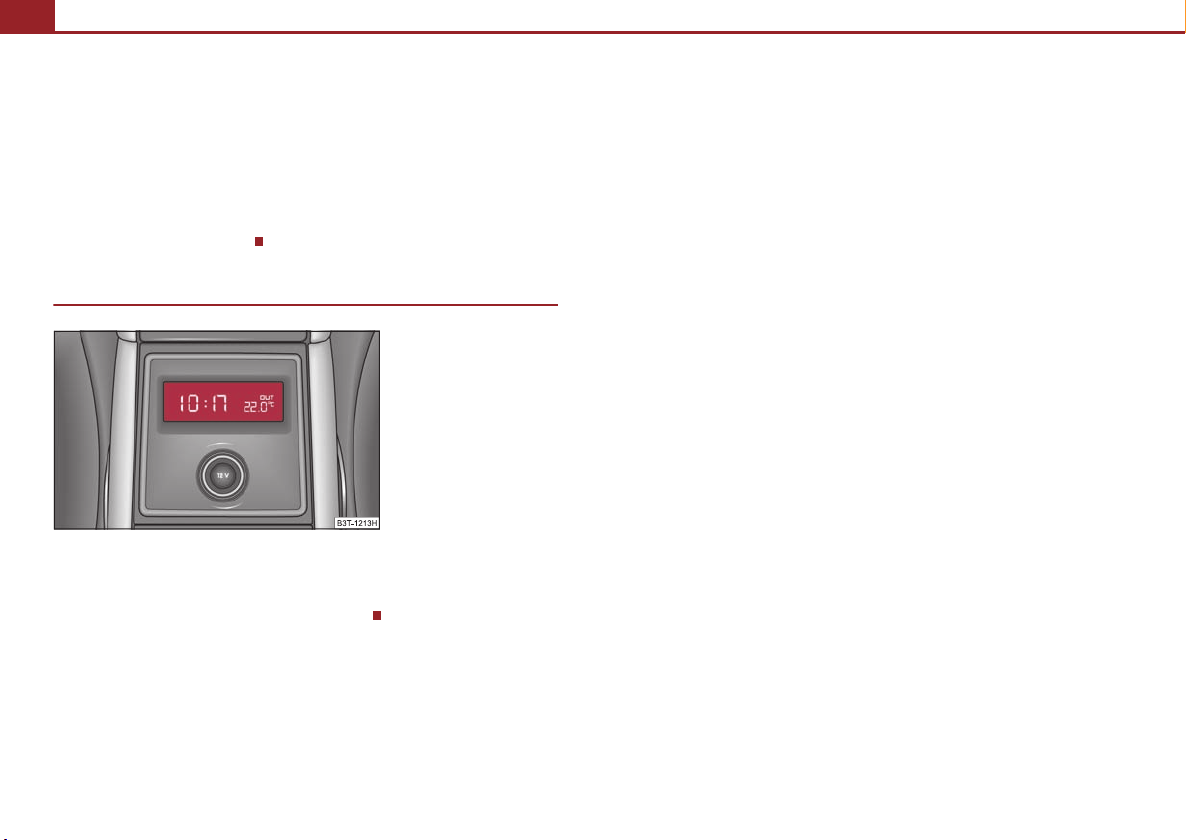
Information display in the rear centre console
Fig. 34 Centre console at
rear: Information disp lay
The time and the outside temperature is displayed on the information display in the
rear centre console when the ignition is switched on ⇒ fig. 34.
The values are taken over by the instrument cluster.
Page 34
Warning lights
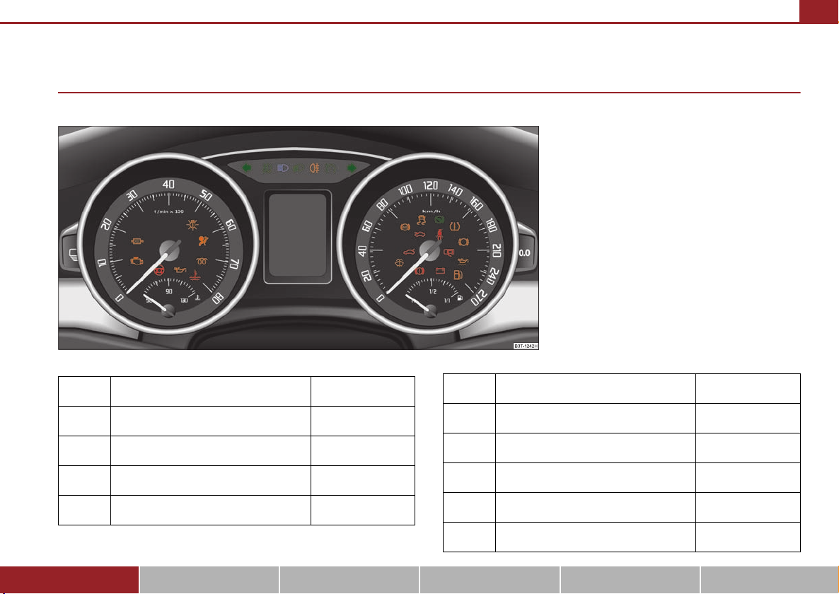
Overview
The warning lights indicate certain functions or faults.
Turn signal lights (to the left) ⇒ page 34
Turn signal lights (to the right) ⇒ page 34
Instruments and Indicator/Warning Lights 33
Fig. 35 Instrument cluster with warning lights
Rear fog light ⇒ page 35
Speed regulating system* ⇒ page 35
Failure of the light bulbs ⇒ page 35
Fog lights ⇒ page 35
Main beam light ⇒ page 35
Low beam ⇒ page 35
Using the system Safety Driving Tips General Maintenance Breakdown assistance Technical Data
Adaptive headlights* ⇒ page 35
Diesel particle filter* (diesel engine) ⇒ page 35
Airbag system ⇒ page 36
Page 35

Instruments and Indicator/Warning Lights34
Control system for exhaust ⇒ page 36
Electromechanical power steering ⇒ page 36
Engine oil pressure ⇒ page 37
EPC fault light (petrol engine) ⇒ page 37
Glow plug system (diesel engine) ⇒ page 37
Coolant temperature/coolant level ⇒ page 38
Traction control system (TCS) ⇒ page 38
Electronic stability programme (ESP)* ⇒ page 39
Selector lever lock* ⇒ page 39
Tyre pressure* ⇒ page 39
Antilock brake system (ABS) ⇒ page 39
Bonnet ⇒ page 40
Seat belt warning light ⇒ page 40
Brake pad wear* ⇒ page 40
Boot lid ⇒ page 41
Open door ⇒ page 41
Fluid level in windshield washer system ⇒ page 41
Brake system ⇒ page 41
Dynamo ⇒ page 42
Engine oil level ⇒ page 42
Fuel reserve ⇒ page 42
WARNING
• If you do not pay attention to th e warning lights coming on and the corre-
sponding descriptions and warning notes, this may result in severe body
injuries or major vehicle damage.
• The engine compartment of your car is a hazardous area. There is a risk
of injuries, scalding, accidents and fire when working in the engine
compartment, e.g. inspecting and replenishing oil and other fluids. It is also
essential to observe all warnings ⇒ page 223, “Working in the engine
compartment”.
Note
• The arrangement of the indicator lights depends on the model version. The
symbols shown in the following functional description are to be found as indicator
lights in the instrument cluster.
• Operational faults are shown in the instrument cluster as red symbols (priority
1 - danger) or yellow symbols (priority 2 - warning).
Turn signal system
Either the left or right indicator light flashes depending on the position of the
turn signal lever.
The indicator light flashes at twice its normal rate if a turn signal light fails. This does
not apply when towing a trailer.
Page 36
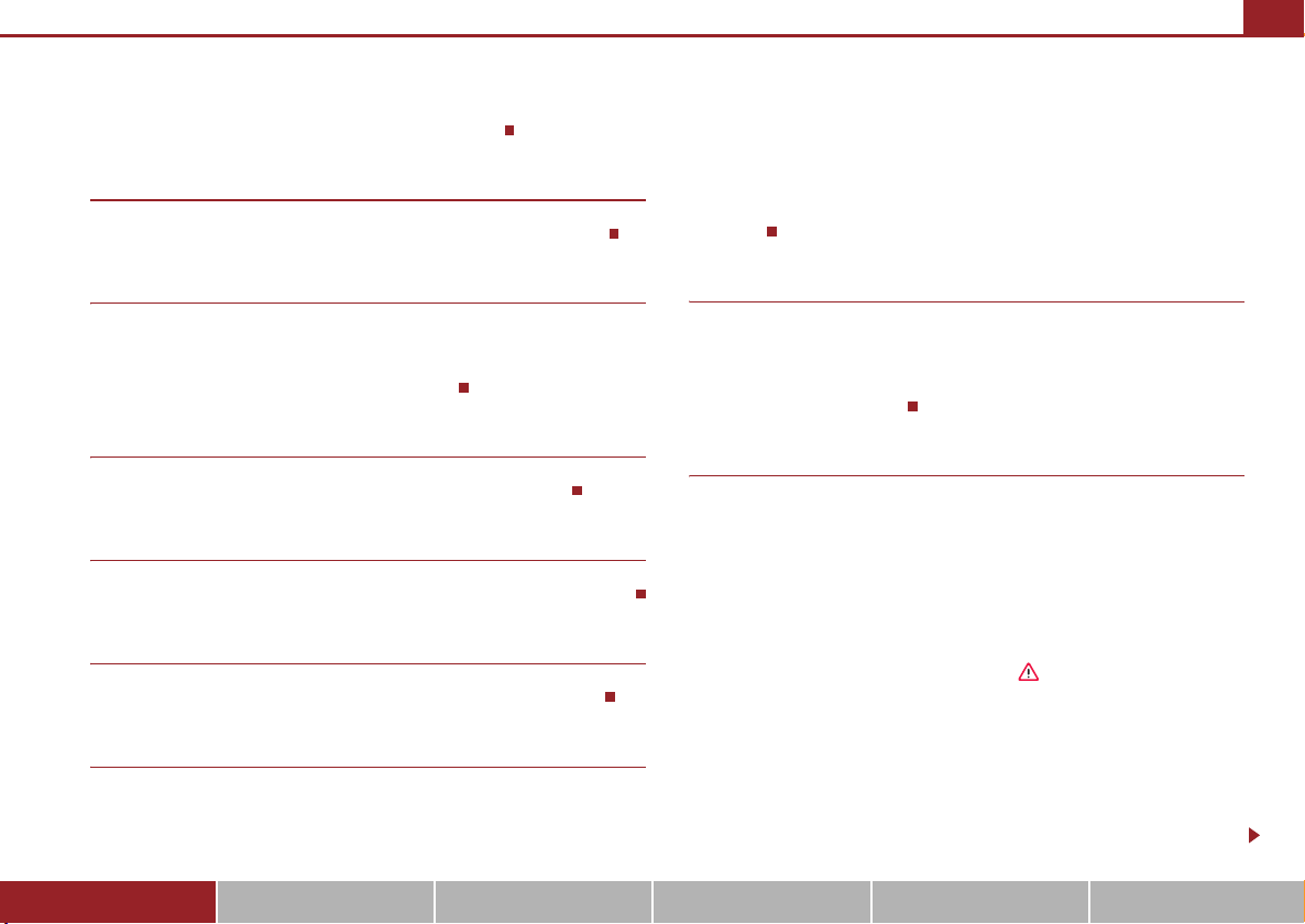
Instruments and Indicator/Warning Lights 35
Switching off the hazard warning light system is switched on will cause all of the
turn signal lights as well as both indicator lights to flash.
Further information about the turn signal system ⇒ page 67.
Fog lights
The warning light comes on when the fog lights are operating ⇒ page 64.
Main beam
The indicator light comes on when the main beam is selected or also when the
headlight flasher is operated.
Further information about the main beam ⇒ page 67.
Low beam
The warning light comes on when low beam is selected ⇒ page 60.
Rear fog light
The warning light comes on when the rear fog lights are operating ⇒ page 65.
Cruise control system*
The warning light lights up, when operating the speed regulating system.
Failure of the light bulbs
The warning light comes on if a light bulb is damaged:
• up to 2 seconds after the ignition is switched on,
• when switching on the defective light bulb.
The following text e.g will be displayed in the information display*:
Check front right dipped beam!
The rear side lights and the licence plate lighting require several light bulbs. The
indicator light only lights up if all light bulbs of the licence plate lighting or the
parking light (in one rear light unit) are defective. Check regularly the function of the
light bulbs.
Adaptive headlights*
If the warning light flashes for 1 minute while driving or after switching on the
ignition and a warning signal sounds, a fault of the adaptive headlights is
confirmed.
Further information ⇒ page 63.
Diesel particle filter* (diesel engine)
If the warning light comes on, this means that soot has accumulated in the
diesel particle filter because of the frequent short distances.
In order to clean the diesel particle filter, the vehicle should be driven at an even
speed of at least 60 km/h at engine speeds of 1 800 - 2 500 rpm for at least 15
minutes or until the warning light goes out with the 4th or 5th gear engaged (automatic gearbox: position S) when the traffic situation permits it. This increases the
exhaust temperature and the soot deposited in the diesel particle filter is burnt.
Always pay attention to the valid speed limits ⇒ .
The warning light goes out after the successful cleaning of the diesel particle
filter.
If the filter is not properly cleaned, the warning light does not go out and the
warning light begins to flash. In the information display* appears Diesel-
particle Owner's manual. Afterwards the engine control unit shifts the engine into
the emergency mode, which only has a reduced power output. After switching the
ignition off and on again the warning light comes on.
Using the system Safety Driving Tips General Maintenance Breakdown assistance Technical Data
Page 37

Instruments and Indicator/Warning Lights36
Have the vehicle inspected without delay by your specialist garage.
WARNING
• If you do not pay attention to the warning light coming on and the corre-
sponding descriptions and warning notes, this may result in injuries or
major vehicle damage.
• Always adjust your speed to suit weather, road, region and traffic condi-
tions. The route indicated by the warning light must not tempt you to disregard the national regulations for road traffic.
Caution
As long as the warning light lights up, one must take into account an increased
fuel consumption and in certain circumstances a power reduction of the engine.
Note
Further information about diesel particle filter ⇒ page 200.
Airbag system
Monitoring the airbag system
The warning light comes on for a few seconds when the ignition is switched on.
There is a fault in the system if the warning light does not go out or flashes while
driving ⇒ . This also applies if the warning light does not come on when the igni-
tion is switched on.
The following text will be displayed in the information display*:
Airbag fault!
The functionality of the airbag system is also monitored electronically, when one
airbag has been switched off
Front, side and head airbags or belt tensioner which have been switched off
using the vehicle system tester:
• The warning light lights up for 4 seconds after switching on the ignition and
then flashes again for 12 seconds afterwards in 2 second intervals.
The following text will be displayed in the information display*:
Airbag/belt tensioner deactivated!
Front passenger airbags switched off using the switch for front passenger
airbags* in storage compartment on the front passenger side:
• the warning light comes on for 4 seconds after the ignition has been
switched on,
• switching off airbags is indicated in the middle of the dash panel by the lighting
up of the warning light (airbag switched off) ⇒ page 183.
WARNING
Have the airbag system checked immediately by a specialist garage if a fault
exists. Otherwise, there is a risk of the airbag not being activated in the event
of an accident.
Control system for exhaust
The warning light comes on after the ignition has been switched on.
If the warning light does not go out after starting the engine or it lights up when
driving, a fault exists in an exhaust relevant component. The engine management
system selects an emergency programme which enables you to drive to the nearest
specialist garage by adopting a gentle style of driving.
Electromechanical power steering
The warning light comes on for a few seconds when the ignition is switched on.
If the warning light after switching on the ignition or when driving lights up continuously, a fault exists in the electromechanical power steering.
• If the yellow warning light lights up , this indicates a partial failure of the
power steering and the steering forces can be greater.
Page 38
Instruments and Indicator/Warning Lights 37
• If the red warning light lights up , this indicates a complete failure of the
power steering and the steering assist has failed (significantly higher steering
forces).
Further information ⇒ page 198.
WARNING
Contact your specialist garage if the power steering is defective.
Note
• If the yellow warning l ight goes out after starting the engine again and a short
drive, it is not necessary to visit a specialist garage.
• If the battery has been disconnected and reconnected, the yellow warning light
comes on after switching on the ignition. The warning light must go out after
driving a short distance.
Engine oil pressure
The warning light comes on for a few seconds 3) when the ignition is switched
on.
Stop the vehicle and switch the engine off if the warning light does not go off
after the engine has started or flashes while driving. Check the oil level and top up
with oil as necessary ⇒ page 225.
An audible signal sounds three times as an additional warning signal.
Do not continue your journey if for some reason it is not possible under the
conditions prevailing to top up with oil. Keep the engine switched off and obtain
professional assistance from a specialist garage, otherwise it could lead to severe
engine damage.
3)
The warning light on vehicles fitted with information display does not come on after
switching the ignition on, but only if a fault exists or the engine oil level is too low.
Do not drive any further if the warning light flashes even if the oil is at the correct
level. Do not run the engine not at idling speed either. Contact the nearest specialist
garage to obtain professional assistance.
The following text will be displayed in the information display*:
Oil Pressure Engine off! Owner's manual
WARNING
• If you must stop for technical reasons, then park the vehicle at a safe
distance from the traffic and switch off the engine and switch on the hazard
warning light system.
• The red oil pressure light is not an oil level indicator! One should
therefore check the oil level at regular intervals, preferably after every refueling stop.
EPC fault light (petrol engine)
The (Electronic Power Control) warning light comes on for a few seconds when
the ignition is switched on.
If the warning light does not go out or lights up after starting the engine, a fault
exists in the engine control. The engine management system selects an emergency
programme which enables you to drive to the nearest specialist garage by adopting
a gentle style of driving.
The following text will be displayed in the information display*:
Engine fault Workshop! (Engine fault workshop!)
Glow plug system (diesel engine)
The warning light lights up for a cold engine when switching on the ignition
(pre-heat position) 2 ⇒ page 118. Star t the engine after the indicator light goes out.
The glow plug indicator light will come on for about 1 second if the engine is at a
normal operating temperature or if the outside temperature is above +5°C. This
means that you can start the engine right away.
Using the system Safety Driving Tips General Maintenance Breakdown assistance Technical Data
Page 39

Instruments and Indicator/Warning Lights38
There is a fault in the glow plug system if the warning light does not come on
at all or lights up continuously. Contact a specialist garage as soon as possible to
obtain assistance.
If the warning light begins to flash while driving, a fault exists in the engine
control. The engine management system selects an emergency programme which
enables you to drive to the nearest specialist garage by adopting a gentle style of
driving.
The following text will be displayed in the information display*:
Engine fault Workshop! (Engine fault workshop!)
Coolant temperature/ Coolant quantity
The warning light comes on for a few seconds 4) when the ignition is switched on.
The coolant temperature is too high or the coolant level too low if the warning light
does not go out or flashes while driving.
3 peeps sound as an additional warning signal.
In this case stop and switch the engine off and check the coolant level; top up the
coolant as necessary.
Do not continue your journey if for some reason it is not possible under the
conditions prevailing to top up with coolant. Keep the engine switched off and
obtain professional assistance from a specialist garage, otherwise it could lead to
severe engine damage.
If the coolant is within the specified range, the increased temperature may be
caused by an operating problem at the coolant fan. Check the fuse for the coolant
fan, replace it if necessary ⇒ page 257, “Fuse assignment in engine compar tment version 1” or ⇒ page 259, “Fuse assignment in engine compartment - version 2”.
Do not continue driving if the warning light doe s not go off although the fluid is at
the correct level and also the fuse of the fan is in proper order. Contact a specialist
garage to obtain assistance.
Please also refer to the additional instructions ⇒ page 226, “Cooling system”.
The following text will be displayed in the information display*:
Check coolant! Owner's manual
WARNING
• If you must stop for technical reasons, then park the vehicle at a safe
distance from the traffic and switch off the engine and switch on the hazard
warning light system ⇒ page 66.
• Take care when opening the coolant expansion bottle. If the engine is hot,
the cooling system is pressurized - risk of scalding! It is best to allow the
engine to cool down before removing the cap.
• Do not touch the coolant fan The coolant fan may switch on automati-
cally even if the ignition is off.
Traction control system (TCS)
The warning light comes on for a few seconds when the ignition is switched on.
The warning light comes on when driving when a control cycle is activated.
The warning light will come on and remains on if the TCS is switched off or if there
is a fault in the system.
The fact that the TCS system operates together with the ABS means that the TCS
warning light will also come on if the ABS system is not operating properly.
If the warning light comes on immediately after starting the engine, the TCS
system can be switched off for technical reasons. In this case, the TCS system can
be switched on again by switching the ignition on and off. If the warning light goes
out, the TCS system is fully functional again.
Further information about the TCS ⇒ page 195, “Traction control system (TCS)”.
4)
The warning light on vehicles fitted with information display does not come on after
switching the ignition on, but only if the coolant temperature is too high or the coolant level
is too low.
Page 40
Instruments and Indicator/Warning Lights 39
Note
If the battery has been disconnected and reconnected, the warning light comes
on after switching on the ignition. The warning lig ht must go out after driving a short
distance.
Electronic stability programme (ESP)*
The warning light comes on for a few seconds when the ignition is switched on.
Components of the ESP system also include the Traction Control System (TCS),
Electronic Differential Lock (EDL), and the Antilock Brake System ABS (ABS).
The warning light comes on when driving when a control cycle is activated.
The warning light will come on and remains on if the ESP is switched off or if there
is a fault in the system.
The fact that the ESP system operates together with the ABS means that the ESP
warning light will also come on if the ABS system is not operating properly.
If the warning light comes on immediately after starting the engine, the ESP
system can be switched off for technical reasons. In this case, the ESP system can
be switched on again by switching the ignition on and off. If the warning light goes
out, the ESP system is fully functional again.
Further information on the ESP ⇒ page 193, “Electronic stability programme
(ESP)*”.
Electronic Differential Lock (EDL)*
The EDL is a part of the ESP. A fault in the EDL is indicated by the ESP warning light
in the instrument cluster. Have the vehicle inspected without delay by an authorised Škoda Service Partner. Further information on the EDL ⇒ page 194, “Electronic
Differential Lock (EDL)*”.
Note
If the battery has been disconnected and reconnected, the warning light comes
on after switching on the ignition. The warning lig ht must go out after driving a short
distance.
Selector lever lock*
If the green warning light lights up, operate the brake pedal. This is necessary, in
order to be able to move the selector lever out of the position P or N.
Tyre inflation pressure*
The warning light lights up, if there is a substantial drop in inflation pressure in
one of the tyres. Reduce the speed and check or correct as soon as possible the
inflation pressure in the tyres ⇒ page 235.
If the warning light flashes, there is a system fault. Visit the nearest specialist garage
and have the fault rectified.
Further information about tyre pressure-control system ⇒ page 199.
WARNING
• When the warning light lights up, immediately reduce the speed and
avoid sudden steering and brake manoeuvres. Please stop the vehicle
without delay at the nearest possible stop and inspect the tyres and their
inflation pressures.
• Under certain circumstances (e.g. sporty style of driving, wintry or
unpaved roads) the warning light can be delayed or does not light up at
all.
Note
If the battery has been disconnected, the warning light comes on after switching
on the ignition. The warning light must go out after driving a short distance.
Antilock brake system (ABS)
The warning light shows the functionality of the ABS.
Using the system Safety Driving Tips General Maintenance Breakdown assistance Technical Data
Page 41
Instruments and Indicator/Warning Lights40
The warning light comes on for a few seconds after the ignition has been switched
on or when starting the engine. The warning light goes out after an automatic check
sequence has been completed.
A fault in the ABS
The system is not functioning properly if the ABS warning light does not go out
within a few seconds after switching on the ignition, does not li ght up at all or lights
up while driving. The vehicle will only be braked by the normal brake system. Visit
a specialist garage as quickly as possible and adjust your style of driving appropriately as you will not know how great the damage is.
Further information about ABS ⇒ page 197, “Antilock brake system (ABS)”.
A fault in the entire brake system
If the ABS warning light comes on together with the brake system warning light
(handbrake must be released), there is a fault not only in the ABS but also in
another part of the brake system ⇒ .
WARNING
• If the brake system warning light comes on together with the ABS
warning light stop the vehicle immediately and check the brake fluid
level in the reservoir ⇒ page 228, “Brake fluid”. If the fluid level has dropped
below the MIN marking, do not drive any further - risk of accident! Obtain
professional assistance.
• Pay attention to the following instructions before checking the brake
fluid level and opening the bonnet ⇒ page 223, “Working in the engine
compartment”.
• If the brake fluid is at the correct level, the ABS control function has
failed. The rear wheels may then block very rapidly when braking. In certain
circumstances, this can result in the rear end of the car breaking away - risk
of skidding! Drive carefully to the nearest specialist garage and have the
fault rectifi ed.
Bonnet
The warning light comes on if the bonnet is unlocked. If the engine bonnet
unlocks while driving , the warning light lights up and an audible signal sounds.
The warning light comes on even when the ignition is switched off. The warning
light lights up for a maximum of 5 minutes.
On vehicles with information display* this warning light is replaced by a vehicle
symbol ⇒ page 28, fig. 29.
Seat belt warning light
The warning light comes on after the ignit ion is switched on as a reminder for the
driver and front passenger to fasten the seat belt. The warning light only goes out if
the driver or front passenger has fastened his seat belt.
If the seat belt has not been fastened by the driver or front passenger, a permanent
warning signal sounds at vehicle speeds greater than 20 km/h and simultaneously
the warning light flashes.
If the seat belt is not fastened by the driver or front passenger during the next 90
seconds, the warning signal is deactiva ted and the warning light lights up permanently.
Further information on the seat belts ⇒ page 168, “Seat belts”.
Thickness of the brake pads*
The warning light comes on for a few seconds 5) when the ignition is switched
on.
If the warning light comes on, contact a specialist garage immediately and have
the brake pads on all of the wheels inspected.
5)
The warning light on vehicles fitted with information display does not come on after
switching the ignition on, but only if a fault exists.
Page 42

Instruments and Indicator/Warning Lights 41
The following text will be displayed in the information display*:
Check brake pads!
Boot lid
The warning light comes on when the ignition is switched on if the luggage
compartment door is open. If the boot lid opens while driving, the warning light
lights up and as a warning an audible signal sounds.
The warning light comes on even when the ignition is switched off. The warning
light lights up for a maximum of 5 minutes.
On vehicles with information display* this warning light is replaced by a vehicle
symbol ⇒ page 28, fig. 29.
Open door
The warning light comes on if one or several doors are opened or if the boot lid
is opened. If one of the doors opens while driving, the warning light lights up
and an audible signal sounds.
The warning light comes on even when the ignition is switched off. The warning
light lights up for a maximum of 5 minutes.
On vehicles with information display* this warning light is replaced by a vehicle
symbol ⇒ page 28, fig. 29.
Liquid in reservoir for windscreen washer system
The warning light comes on when the ignition is switched on if there is insufficient fluid in the windshield washer system. Top up with liquid ⇒ page 234.
The following text will be displayed in the information display*:
Add wash fluid!
Brake system
The warning light flashes or comes on if the brake fluid level is too low, if there
is a fault in the ABS or if the handbrake is applied.
If the warning light flashes and an audible signal sounds three times (handbrake
is not applied), stop and check the brake fluid level ⇒ .
The following text will be displayed in the information display*:
Brake fluid Owner's manual
If there is a fault in the ABS which also influences the function of the brake system
(e.g. distribution of brake pressure), the ABS warning light comes on and at the
same time the brake system warning light starts flashing . Be aware that not only
the ABS but also another part of th brake system is defective ⇒ .
An audible signal sounds three times as an additional warning signal.
One should get used to high pedal forces, long braking distances and long free play
of the brake pedal when driving to the next specialist garage.
For further information on the brake system ⇒ page 196, “Brakes”.
Handbrake applied
The warning light also comes on if the handbrake is applied. An audible warning
is also given if you drive the vehicle for at least 3 seconds at a speed of more than 6
km/h.
The following text will be displayed in the information display*:
Release parking brake!
WARNING
• Pay attention to the following instructions before checking the brake
fluid level and opening the bonnet ⇒ page 223, “Working in the engine
compartment”.
• If the brake system warning light does not go out a few seconds after
switching on the ignition or comes on when driving, stop immediately and
check the brake fluid in the reservoir ⇒ page 228, “Brake fluid”. If the fluid
Using the system Safety Driving Tips General Maintenance Breakdown assistance Technical Data
Page 43
Instruments and Indicator/Warning Lights42
WARNING (continued )
level has dropped below the MIN marking, do not drive any further - risk of
accident! Obtain professional assistance.
Alternator
The warning light comes on after the ignition has been switched on. It should go
out after the engine has started.
If the warning light does not go out after the engine has started, or comes on when
driving, drive to the nearest specialist garage. The vehicle battery will be discharged
in this case so switch off all non-essential electrical components.
Caution
If the warning light comes on when driving and in addition the warning light
(cooling system fault) also comes on in display, you must then stop the car immediately and switch the engine off - risk of engine damage!
Engine oil level
Warning light lights up
If the warning light lights up, the quantity of oil in the engine is probably too low.
Check as soon as possible the oil level or top up ⇒ page 225 with engine oil.
A peep sounds as an additional warning signal.
The following text will be displayed in the information display*:
Check oil level!
The warning light will go out if the bonnet is left open for more than 30 seconds. If
no engine oil has been replenished, the warning light will come on again after
driving about 100 km.
Warning light flashes
A fault on the engine oil level sensor is indicated additionally by an audible signal
and the warning light coming on several times after the ignition has been switched
on.
In this case have the engine inspected without delay by a specialist garage.
The following text will be displayed in the information display*:
Oil sensor Workshop!
Fuel reserve
The warning light comes on, if the fuel level is still below 9 litres.
An audible signal sounds as an additional warning signal.
The following text will be displayed in the information display*:
Please refuel! Range...km
Note
The Text in the information display* goes out only after refuelling and driving a
short distance.
Page 44
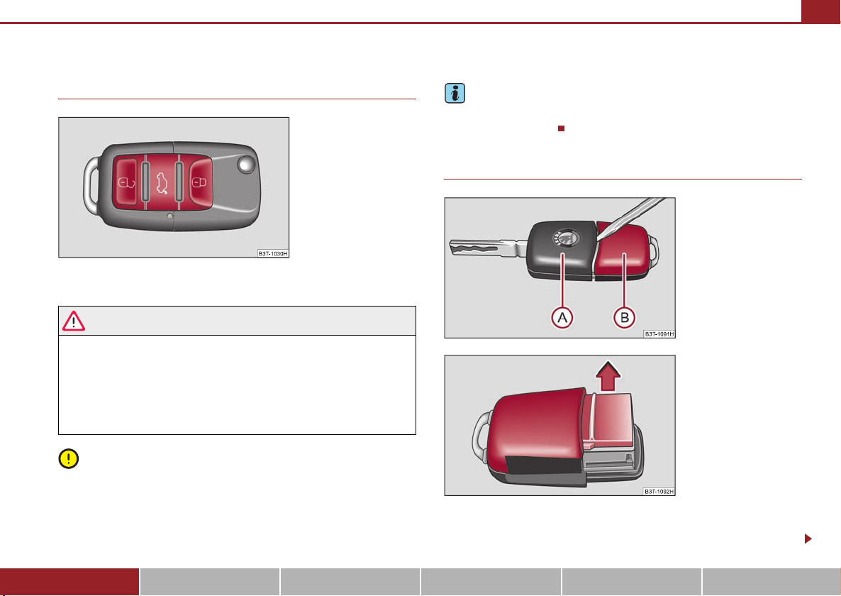
Unlocking and locking
A
Unlocking and locking 43
Key
Fig. 36 Remote control key
Two remote control keys are provided with the vehicle ⇒ fig. 36.
WARNING
• Always withdraw the key whenever you leave the vehicle - even if it is
only for a short time. This is particularly important if children are left in the
vehicle. The children might otherwise start the engine or operate electrical
equipment (e.g. power windows) - risk of injury!
• Do not withdraw the ignition key from the ignition lock until the vehicle
has come to a stop. The steering lock might otherwise engage unintentionally - risk of accident!
Caution
• Each key contains electronic components; therefore protect them against mois-
ture and severe shocks.
• Keep the groove of the keys absolutely clean as impurities (textile fibres, dust
etc.) have a negative effect on proper operation of the keys and the ignition lock.
Note
Please approach an authorised Škoda Service Partner if you lose a key since he can
obtain a new one for you.
Changing the battery of the radio remote control
Fig. 37 Disconnect key with
radio remote con trol
Fig. 38 Cover of the transmitter housing
Each remote control key contains a battery which is housed in the cover
B
of the transmitter housing ⇒ fig. 37. We recommend that you have
Using the system Safety Driving Tips General Maintenance Breakdown assistance Technical Data
Page 45
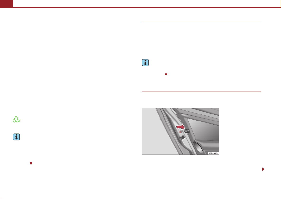
Unlocking and locking44
AAA
the batteries of the key replaced by an authorised Škoda Service Partner.
You should, however, proceed as follows if you wish to replace the battery
yourself:
– Fold open the key.
– Use a thin screwdriver to carefully lever off the front part of the key
⇒ page 43, fig. 37 from the transmitter housing .
B
– Take off the cover of the transmitter housing ⇒ page 43, fig. 38 in
direction of arrow.
– Take the used battery out of the housing cover.
– Insert the new battery. Ensure that the “+” symbol on the battery is
facing downwards. The correct polarity is also shown on the cover of
the transmitter housing.
– Insert cover with battery in place at the rear of the transmitter housing
and press both parts together.
– Insert the transmitter housing into the front part of the key so that the
two parts lock into each other.
For the sake of the environment
Dispose of an old battery in accordance with environmental regulations.
Note
• The replacement battery must have the same specification as the original
battery.
• If it is still not be possible to unlock or lock the vehicle with the remote control
even after replacing the battery this means that the system has to be synchronised
⇒ page 52.
Electronic immobiliser
The electronic immobiliser prevents the vehicle being operated by an
unauthorised person.
An electronic chip is integrated in the head of the key. The immobiliser is deactivate d with t he aid o f this c hip whe n the key is inse rted i n the ig nition lock. T he elec tronic immobiliser is automatically activated when you withdraw the ignition key
from the lock.
Note
It is only possible to start the engine of your car with a Genuine Škoda key with the
matching code.
Child safety lock
The child safety lock prevents the rear door from being opened from
the inside.
Fig. 39 Child safety locks on
the rear doors
The rear doors are equipped with a child safety lock. You can switch the
child safety lock on and off using the vehicle key.
Page 46
Unlocking and locking 45
Switching child safety lock on
– Use the vehicle key to turn the slit in the rear door to the left in the
direction of the arrow ⇒ page 44, fig. 39.
Switching child safety lock off
– Use the vehicle key to turn the slit to the right against the direction of
the arrow.
So long as the child safety lock is switched on it is not possible to open the door
from the inside with the door opening lever. In this case the door can be opened
only from the outside.
Central locking system
Description
Unlocking or locking the vehicle causes all the doors and the fuel filler flap to be
unlocked or locked at the same time by the central locking system. The boot lid is
unlocked when opening. Afterwards you can open the boot lid by pressing the
handle on the lower edge of the boot lid ⇒ page 48.
Operation of the central locking system is possible:
• by using the radio remote control ⇒ page 51,
• using the buttons for the central locking system ⇒ page 46,
• from the outside using the vehicle key ⇒ page 47, “Emergency unlocking and
locking of the driver's door”.
Indicator light in the driver's door
After locking the vehicle the indicator light flashes for 2 seconds fast, then more
slowly.
If the vehicle is locked and the safe securing system ⇒ page 46 is not operating, the
indicator light in the driver door flashes for about 2 seconds fast, goes out and starts
to flash slowly after about 30 seconds.
If the indicator light first of all flashes fast for about 2 seconds, afterwards lights up
for about 30 seconds without interruption and then flashes slowly, there is a fault in
the system of the central locking or in the interior monitor and in the towing protection monitoring* ⇒ page 53. Visit a specialist garage to obtain assistance.
Convenience operation of windows
One can open and close the windows when opening and closing the vehicle
⇒ page 56.
Opening a single door*
This function allows one to just unlock the driver's door. The other doors and the
fuel filler flap remain locked and are only unlocked after repetitive unlocking.
You can have the function opening a single door activated by an authorised Škoda
Service Partner on request or you can activate it yourself with the aid of the Information display* ⇒ page 30.
Automatic locking*
All the doors and the boot lid are locked automatically once the car reaches a speed
of about 15 km/h.
If the ignition key is withdrawn, the car is then automatically unlocked again. In
addition, it is possible for the driver or front passenger to unlock the car by pressing
the central locking button ⇒ page 46 or by pulling the door opening lever on one
of the front doors.
You can have the function of the automatic locking activated by a specialist garage
on request or you can also activate it yourself with the aid of the Information
display* ⇒ page 30.
WARNING
Locking the doors prevents involuntary opening in an exceptional situation
(an accident). Locked doors prevent unwanted entry into the vehicle from
outside, for example at road crossings. Locked doors do, however, make it
more difficult for rescuers to get into the vehicle in an emergency - danger to
life!
Using the system Safety Driving Tips General Maintenance Breakdown assistance Technical Data
Page 47
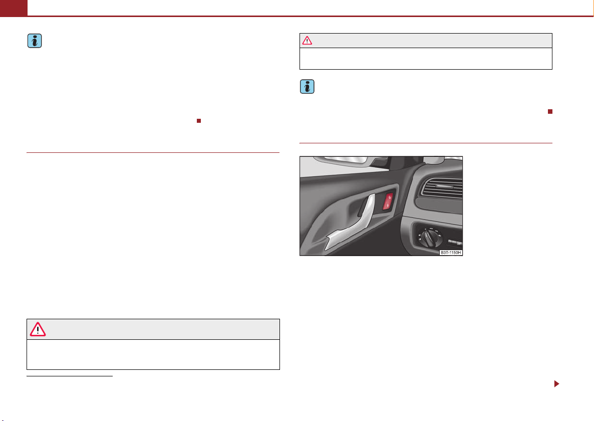
Unlocking and locking46
Note
• In the event of an accident in which the airbags are deployed, the locked doors
are automatically unlocked in order to enable rescuers to gain access to the vehicle.
• Only the driver's door can be unlocked or locked using the key if the central
locking system fails ⇒ page 47, “Emergency unlocking and locking of the driver's
door”. You can lock or unlock manually the other doors and the boot lid.
− Emergency locking of the door ⇒ page 48.
− Emergency unlocking of the boot lid ⇒ page 50.
Safe securing
The central locking system is equipped with a safe securing6) system. Locking the
vehicle from the outside causes the door locks to be automatically blocked. It is not
possible to open the doors with the door handle either from the inside or from the
outside. This acts as an effective deterrent for attempts to break into your vehicle.
You can deactivate the safe securing system by locking twice within 2°seconds.
If the safe securing system is not operating:
• the indicator light in the driver door flashes for about 2 seconds fast, goes out
and starts to flash slowly after about 30 seconds,
• is the filler flap locked.
The safe securing system is again activated the next time the vehicle is unlocked and
locked again.
If the vehicle is locked and the safe securing system is deactivated, you can open
the vehicle from the inside by pulling on the door opening lever.
WARNING
If the vehicle is locked from the outside and the safe securing system is activated, there must not be any person and animals in the vehicle as it is then
not possible to open either a door or a window from the inside. The locked
6)
Only valid for some countries.
WARNING (continued )
doors make it more difficult for rescuers to get into the vehicle in an emergency - hazard!
Note
The anti-theft alarm system* is also activated with the deactivated safe securing
system when locking the vehicle. The interior monitor* is however not activated.
Button for the central locking system
Fig. 40 Button for the central
locking system
If the vehicle was not locked from the outside, you can also unlock and
lock it with the rocker switch on the door opening lever of the driver or
front passenger door even without the ignition switched on.
Locking all doors and the boot lid
– Press on the bottom part of the button ⇒ fig. 40. The symbol
in the
button comes on.
Unlocking all doors and the boot lid
– Press on the top part of the button ⇒ fig. 40. The symbol
goes out
in the button.
Page 48
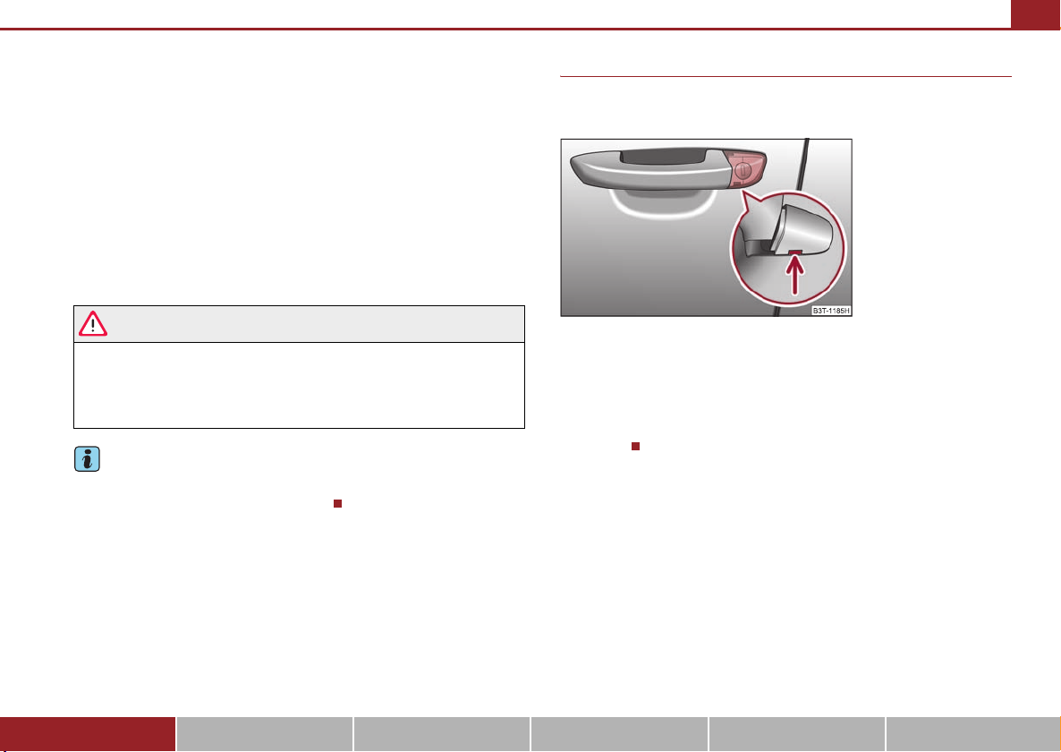
Unlocking and locking 47
The following applies if you have locked your vehicle using the central locking
system:
• It is not possible to open the doors or the boot lid from the outside (safety
feature, e.g. when stopping at traffic lights etc.).
• You can unlock the doors individually from the inside and open them by pulling
the door opening lever.
• If at least one door has been opened, the vehicle cannot be locked.
• In the event of an accident in which the airbags are deployed, the locked doors
are automatically unlocked from the inside in order to enable rescuers to gain
access to the vehicle.
By pressing and holding down the top and bottom part of the rocker switch in the
driver's door, you can conveniently close or open the windows.
WARNING
The central locking system also operates if the ignition is switched off. All the
doors and the boot lid are locked. Children should never be left unattended
in the vehicle since it is difficult to provide assistance from the outside when
the doors are locked. Locked doors make it difficult for rescuers to get into
the vehicle in an emergency - hazard!
Note
The door opening lever and the buttons for the central locking system do not
operate if the safe securing system is activated.
Emergency unlocking and locking of the driver's door
If the remote control key or the central locking system does not
operate, the driver's door can be unlocked or locked manually.
Fig. 41 Handle on the
driver's door: covered
locking cylinder
– Pull on the handle.
– Guide the vehicle key into the recess on the bottom side of the cover
and lift it up to the top.
– Put the vehicle key into the locking cylinder and unlock or lock the
vehicle.
Using the system Safety Driving Tips General Maintenance Breakdown assistance Technical Data
Page 49
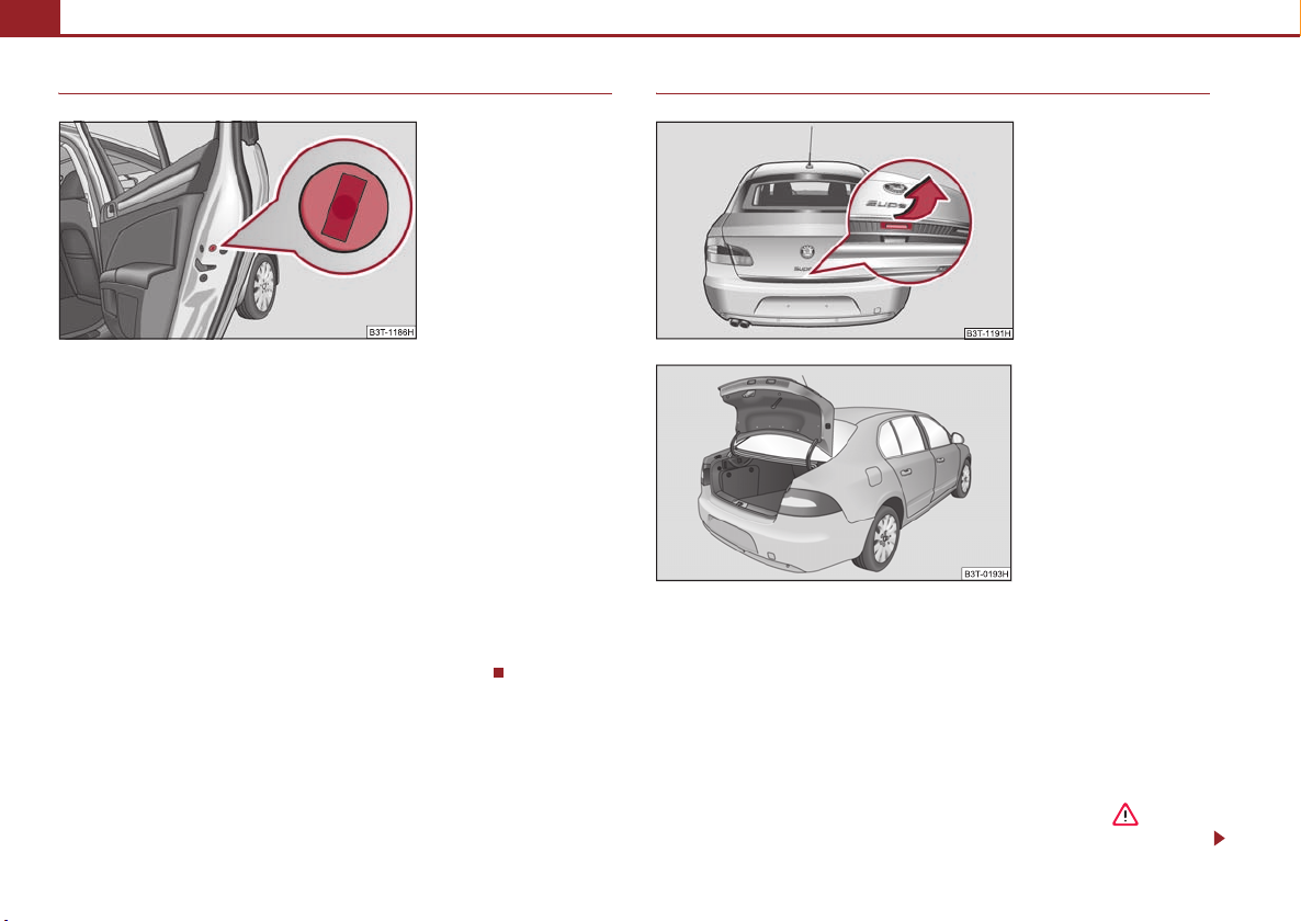
Unlocking and locking48
Emergency locking of the doors
Fig. 42 Rear door: Emergency locking of the door
An emergency locking mechanism is located on the face side of the doors
which have no locking cylinder, it is only visible after opening the door.
Lock the doors using the vehicle key.
Locking
– Remove the panel ⇒ fig. 42.
– Guide the key into the slot and turn it to the outside.
– Re-insert the panel.
After closing the door, you can no longer open it from outside. If the child safety
lock is not switched on, it is possible to open the door from the inside by pulling on
the door handle. If the child safety lock is switched on, it is necesary to also open
the door from outside besides pulling on the inner door handle.
Twindoor - small boot lid
Fig. 43 Handle of boot lid
Fig. 44 Boot lid
After unlocking the vehicle using the radio remote control or the key
⇒ page 47 you can open the small boot lid ⇒ fig. 44.
Open small boot lid
– Press on the handle at the bottom side of the boot lid ⇒ fig. 43, the
boot lid lifts up automatically ⇒ fig. 44.
Close small boot lid
– Pull the boot lid down and close it with a slight swing ⇒ . The
bonnet locks automatically.
Page 50
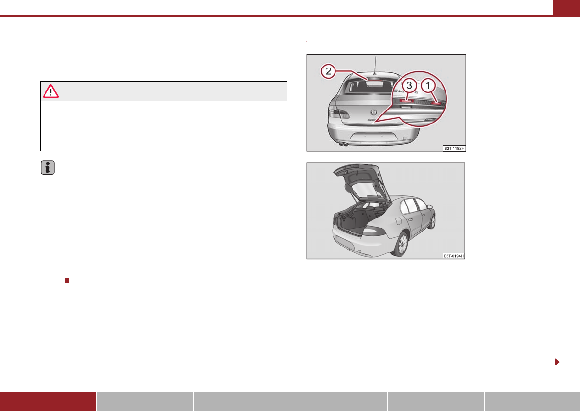
Unlocking and locking 49
A2A
A
A
A
You can also open the small boot lid by pressing the button on the remote
control ⇒ page 51 for approx. 2 seconds.
A handle which makes the closing easier is located on the inner paneling of the
boot lid.
WARNING
• Ensure that the lock is properly engaged after closing the boot lid. Other-
wise, the boot lid might open suddenly when driving even if the boot lid lock
is closed - risk of accident!
• Never drive with the boot lid fully opened or slightly ajar otherwise
exhaust gases may get into the interior of the vehicle - risk of poisoning!
Hinweis
• After closing the boot lid, it is automatically locked within 2 seconds and
the anti-theft alarm system* is activated. This applies only if the vehicle was
locked before closing the boot lid.
• The function of the hand grip on the bottom edge of the boot lid is deactivated
when starting off or as of a speed of more than 5 km/hour. The function of the hand
grip is acitvated again after stopping the vehicle and after opening the driver or
front passenger door or after pressing the button on the radio remote control
⇒ page 51.
1
• Repeated opening and closing of the boot lid can lead to a temporary failure of
the function due to the overheating protection of the motors of the Twindoor
system.
Twindoor - large boot lid
Fig. 45 Handle of boot lid
Fig. 46 Boot lid
After unlocking the vehicle using the radio remote control or the key
⇒ page 47, “Emergency unlocking and locking of the driver's door” you
can open the large boot lid ⇒ fig. 46.
Open large boot lid
– Press the handle ⇒ fig. 45 on the bottom edge of the boot lid.
– You must wait u ntil the brake ligh t in th e rea r win dow fl ashe s twic e.
– Press on the handle and at the same time raise the boot lid.
1
2
3
Using the system Safety Driving Tips General Maintenance Breakdown assistance Technical Data
Page 51
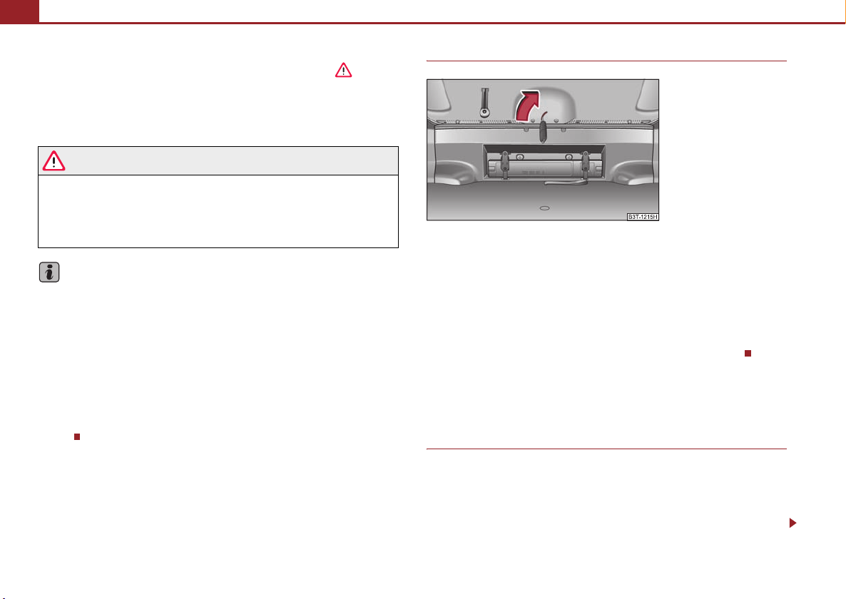
Unlocking and locking50
A
Close large boot lid
– Pull the boot lid down and close it with a slight swing ⇒ . The
bonnet locks automatically.
A handle which makes the closing easier is located on the inner paneling of the
boot lid.
WARNING
• E nsure that t he lo ck is properly engaged after closing the boot lid. Other-
wise, the boot lid might open suddenly when driving even if the boot lid lock
is closed - risk of accident!
• Never drive with the boot lid fully opened or slightly ajar otherwise
exhaust gases may get into the interior of the vehicle - risk of poisoning!
Hinweis
• After closing the boot lid, it is automatically locked within 2 seconds and
the anti-theft alarm system* is activated. This applies only if the vehicle was
locked before closing the boot lid.
• The function of the hand grip on the bottom edge of the boot lid is deactivated
when starting off or as of a speed of more than 5 km/hour. The function of the hand
grip is acitvated again after stopping the vehicle and after opening the driver or
front passenger door or after pressing the button on the radio remote control
⇒ page 51.
1
• Repeated opening and closing of the boot lid can lead to a temporary failure of
the function due to the overheating protection of the motors of the Twindoor
system.
Emergency unlocking of the boot lid
Fig. 47 Emergency
unlocking of the boot lid
If there is a fault in the central locking, you can open the boot lid as
follows:
– Fold the seat backrest forwards ⇒ page 84.
– Guid e the key into the slot in the trim pa nel as fa r as the stop ⇒ fig. 47.
– You can unlock the boot lid by moving in the direction of arrow.
– Open the boot lid/luggage compartment door from outside.
Remote control
Description
You can use the remote control:
• to unlock and lock the car,
• unlock or open the boot lid,
• Opening and closing window.
Page 52

Unlocking and locking 51
A1A
A2A2A2A
The transmitter with the battery is housed in the handle of the remote control key.
The receiver is located in the interior of the car. The operating range of the remote
control is approx. 30 m. But this range of the remote control can be reduced if the
batteries are weak.
The remote control key has a fold-open key bit which can be used for unlocking and
locking the car manually and also for starting the engine.
If a lost key is replaced or if the receiver unit has been repaired or a new unit
installed, it is then necessary for an authorised Škoda Service Partner to initialise the
system. Only after this is it possible to again use the remote control.
Note
• The remote control is automatically deactivated when the ignition is switched
on.
• The operation of the remote control may temporarily be affected by interfer-
ence from transmitters close to the car and which operate in the same frequency
range (e.g. mobile phone, TV transmitter).
• The battery must be replaced, ideally by an authorised Škoda Service Partner, if
the central locking or anti-theft alarm system does react to the remote control at
less than 3 metres away.
• If the driver door is opened, the vehicle cannot be locked using the remote
control.
Unlocking and locking car
Fig. 48 Remote control key
Unlocking the vehicle
– Press button for about 1 second.
Locking the vehicle
– Press button for about 1 second.
Deactivating safe securing system
– Press button twice in 3 seconds. Further information ⇒ page 46.
Small boot lid release
– Press button for about 1 second ⇒ fig. 48. Further information
⇒ page 48.
Automatic raising of the small boot lid
– Press button for about 2 second ⇒ fig. 48. Further information
⇒ page 48.
3
Folding out of the key
–Press button .
Using the system Safety Driving Tips General Maintenance Breakdown assistance Technical Data
4
Page 53

Unlocking and locking52
A
A
Folding up of the key
– Press button and collapse the key bit in the housing.
The turn signal lights flash twice as confirmation that the vehicle has been
unlocked. The vehicle will lock again automatically if you unlock the vehicle using
1
button but do not open a door or the boot lid within the next 30 seconds. This
function is intended to prevent the car being unlocked unintentionally.
In addition, when the car is unlocked, the power seats and exterior mirrors* move
into the position assigned to this key. The stored setting of driver seat and exterior
mirrors is retrieved.
When the vehicle is unlocked or locked, the interior lights and the ligh ts of the entry
area are automatically switched on or off via the door contact.
Display of the locking
The turn signal lights flash once to confirm that the vehicle has been correctly
locked.
If the doors or the boot lid remain open after the vehicle has been locked, the turn
signal lights do not flash until they have been closed.
4
WARNING
If the vehicle is locked from the outside and the safe securing system is activated, there must not be any person in the vehicle as it is then not possible
to open either a door or a window from the inside. The locked doors make it
more difficult for rescuers to get into the vehicle in an emergency - hazard!
Note
• Operate the radio remote control only when the doors and boot lid are closed
and you have visual contact with the vehicle.
• Once in the car, you must not press the lock button of the radio remote
control before inserting the key into the ignition lock in order to avoid the car being
inadvertently locked and, in addition, the anti-theft alarm system* being switched
on. Should this happen, press the unlock button of the radio remote control.
• The automatic raising of the small boot lid can be impaired at temperatures
below +4°C.
Synchonisation of the remote control
If the vehicle cannot be unlocked by actuating the remote control system then it is
possible that the code in the key and the control unit in the vehicle are no longer
synchronised. This can occur when the buttons on the radio-operated key are actuated a number of times outside of the operative range of the equipment or the
battery on the remote control was replaced.
This means it is necessary to synchronise the code as follows:
• Press any button on the remote control.
• Pressing of the button means that the door will unlock with the key within 1
minute ⇒ page 47, “Emergency unlocking and locking of the driver's door”.
Anti-theft alarm system*
Description
The anti-theft alarm system increases the level of protection against people seeking
to break into the vehicle. The system triggers audible and visual warning signals if
an attempt is made to break into the vehicle.
How is the alarm system activated?
The anti-theft alarm system is activated when the vehicle is locked with the key in
the driver's door or by using the radio remote control ⇒ page 47, “Emergency
unlocking and locking of the driver's door”. The door contact monitoring is activated approx. 15 seconds after the locking. The interior and the towing protection
monitoring are activated approx. 30 seconds after the locking. If a door is opened
during activation, the monitoring is only activated 5 seconds after closing.
Page 54

Unlocking and locking 53
How is the alarm system deactivated?
The alarm system is deactivated by pressing the unlock button on the radio remote
control. The vehicle is automatically locked again if the vehicle is not opened within
30 seconds after reactivating the anti-theft alarm system.
The alarm system is also deactivated if you unlock the vehicle door using the key
within 45 seconds after locking the vehicle.
Once you unlock the vehicle by inserting the key into the driver door within 45
seconds, you then have to insert the key into the ignition lock and switch the ignition on within 15 seconds after unlocking the door in order to deactivate the alarm
system. The alarm will be triggered if you do not switch on the ignition within 15
seconds.
When is the alarm triggered?
The following security areas of the locked vehicle are monitored:
• Bonnet,
• Boot lid,
• Doors,
• Ignition lock,
• Socket of the factory-fitted towing device,
• Angle of the vehicle*,
• Vehicle interior*,
• A drop in voltage of the on-board power supply.
An alarm is immediately triggered if either of the two battery terminals is disconnected while the anti-theft alarm system is activated.
How is the alarm switched off?
You switch the alarm off if you unlock the car with the radio remote control in the
key or if you switch the ignition on.
Note
• The working life of the alarm siren is 6 years. More detailed information is avail-
able by a specialist garage.
• Before leaving the car, check that all the doors, windows and the electric
sliding/tilting roof* are properly closed in order to ensure that the anti-theft alarm
system is fully operational.
• Coding of the radio remote control and the receptor part precludes the use of
the radio remote control from other vehicles.
Interior monitor and towing protection monitoring*
The interior monitor detects movements inside the car and then triggers the alarm.
Fig. 49 Button for interior
monitor and towing protection monitoring
Switch off the interior monitor and towing protection monitoring
– Switch off the ignition.
– Open the driver door.
– Press the button
the symbol
orange.
– Lock the vehicle within 30 seconds.
The interior monitor and the towing protection monitoring are switched on again
automatically the next time the car is locked.
at the centre column on the driver side ⇒ fig. 49,
which lights up in the button changes from red to
Using the system Safety Driving Tips General Maintenance Breakdown assistance Technical Data
Page 55
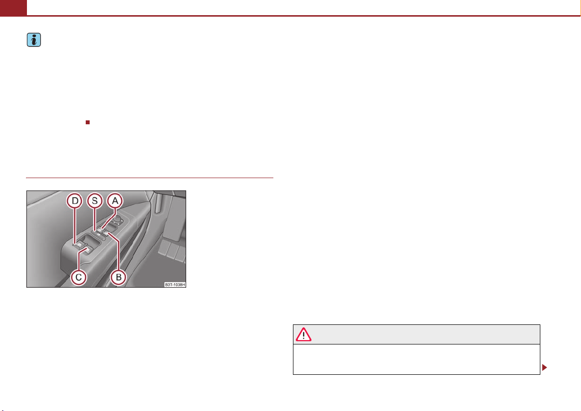
Unlocking and locking54
AAABACADASA
ASA
Note
• You can switch the interior monitor and the towing protection monitoring off if
there is a possibility that movements from (e.g. children or animals) inside the
vehicle interior or if the vehicle must be transported (e. g. by train or ship) or towed,
might trigger the alarm.
• The opened storage compartment for spectacles* reduces the effectiveness of
the interior monitor. In order to ensure the function of the interior monitor to be
fully operational, always close the storage compartment for spectacles before
locking the vehicle.
Power windows
Buttons on the driver's door
Fig. 50 Buttons on the
driver's door
The power windows operate only when ignition is switched on.
Opening a window
– A window is opened by pressing lightly on the respective button in the
door. The process stops when one releases the button.
– Additionally you can open the window automatically (fully opened) by
pressing the button up to the stop. Renewed pressing of the button
causes the window to stop immediately.
Closing a window
– A window is closed through pulling lightly on the respective button in
the door. The closing process stops when one releases the button.
– Additionally you can close the window automatically (fully closed) by
pulling the button up to the stop. Renewed pulling of the button
causes the window to stop immediately.
The switches for the individual windows are located in the armrest for the driver
⇒ fig. 50, front passenger and in the rear doors ⇒ page 55, fig. 51.
Buttons for the power windows in the armrest for the driver
Button for the power window in the driver's door
Button for the power window in the front passenger's door
Button for the power window at the rear right door
Button for the power window at the rear left door
Safety switch
Safety pushbutton
You can deactivate the switches for power windows at rear doors by pressing the
safety pushbutton ⇒ fig. 50. The buttons for power windows at rear doors are
activated again by pressing the safety pushbutton again.
If the buttons for the rear doors are deactivated, the indicator light in the safety
S
switch lights up.
S
WARNING
• If you lock the vehicle from the outside, do not leave any person in the
vehicle since it is no longer possible to open the windows from the inside in
an emergency.
Page 56
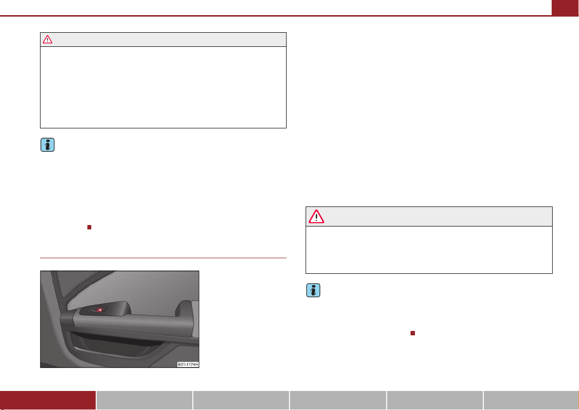
Unlocking and locking 55
A
WARNING (continued )
• The system is fitted with a force limiter ⇒ page 56. If there is an obstacle,
the closing process is stopped and the window goes down by several centimeters. You should then take particular care when closing the windows! You
may otherwise suffer severe injuries as a result of getting an arm, for
example, jammed in the window!
• It is recommended to deactivate the electrically operated power
windows in the rear doors (safety pushbutton) ⇒ page 54, fig. 50 when
children are being transported on the rear seats.
Note
S
• After switching the ignition off, it is still possible to open or close the windows
for a further 10 minutes. The automatic window closing will not operate during this
time. The power windows are switched off completely once you open the driver or
front passenger door.
• When driving always use the existing heating, air conditioning and ventilation
system for ventilating the interior of the vehicle. If the windows are opened, dust as
well as other dirt can get into the vehicle and in addition the wind noise is more at
certain speeds.
Button in front passenger door and in rear doors
A button for the relevant window is provided in these doors.
Opening a window
– A window is opened by pressing lightly on the respective button in the
door. The process stops when one releases the button.
– Additionally you can open the window automatically (fully opened) by
pressing the button up to the stop. Renewed pressing of the button
causes the window to stop immediately.
Closing a window
– A window is closed through pulling lightly on the respective button in
the door. The closing process stops when one releases the button.
– Additionally you can close the window automatically (fully closed) by
pulling the button up to the stop. Renewed pulling of the button
causes the window to stop immediately.
WARNING
The system is fitted with a force limiter ⇒ page 56. If there is an obstacle, the
closing process is stopped and the window goes down by several centimeters. You should then take particular care when closing the windows! You
may otherwise suffer severe injuries as a result of getting an arm, for
example, jammed in the window!
Note
After switching the ignition off, it is still possible to open or close the windows for a
further 10 minutes. The automatic closing and opening functions will not operate
during this time. The power windows are switched off completely once you open
the driver or front passenger door.
Fig. 51 Arrangement of the
switch in a rear door
Using the system Safety Driving Tips General Maintenance Breakdown assistance Technical Data
Page 57

Unlocking and locking56
Force limiter of the power windows
The electrically operated power windows are fitted with a force limiter. It reduces
the risk of bruises or injuries when closing the windows.
If there is an obstacle, the closing process is stopped and the window goes down by
several centimeters.
If the obstacle prevents the window from being closed during the next 10 seconds,
the closing process is interrupted once again and the window goes do wn b y s eve ral
centimeters.
You must try to close the window once again within 10 seconds after the window
has gone down twice, even if the obstacle was not yet removed, the closing process
is stopped. During this time it is not possible to automatically close the window. The
force limiter is still switched on.
The force limiter is only switched off, if you attempt to close the window within the
next 10 seconds - the window closes now with full strength!
If you wait longer than 10 seconds, the force limiter is switched on again.
WARNING
You should take particular care when closing the windows! You may otherwi se s uff er s eve re i nju rie s a s a re sul t o f ge tti ng a n a rm, for exa mpl e, j amm ed
in the window!
Window convenience operation
You can open and close the electrically powered windows as follows when
unlocking and locking the vehicle (just closing of the sliding roof).
Opening a window
• by holding the pressed unlock button on the remote control,
• by holding the pressed top part of the button for the central locking system in
the driver door,
• by holding the key in the driver's lock in the unlock position ⇒ page 47, “Emer-
gency unlocking and locking of the driver's door”.
Closing a window
• by holding the pressed lock button on the remote control,
• by holding the pressed bottom part of the button for the central locking system
in the driver door,
• by holding the key in the driver's lock in the lock position ⇒ page 47.
You can interrupt the opening or closing operation of the windows immediately by
releasing the key or the lock button.
WARNING
The system is fitted with a force limiter ⇒ page 56. If there is an obstacle, the
closing process is stopped and the window goes down by several centimeters. You should then take particular care when closing the windows! You
may otherwise suffer severe injuries as a result of getting an arm, for
example, jammed in the window!
Note
The convenience opening of the windows with the aid of the key in the driver's lock
is only possible within 45 seconds after deactivating or activating the alarm
system.
Operational faults
Electrically operated power windows do not operate
If the battery has been disconnected and then reconnected while the window was
opened, the electrically operated power windows do not operate. The system must
be activated. Proceed as follows in order to re-establish the function:
• you can close the window by pulling the respective switch on the top edge
• release the switch
Page 58
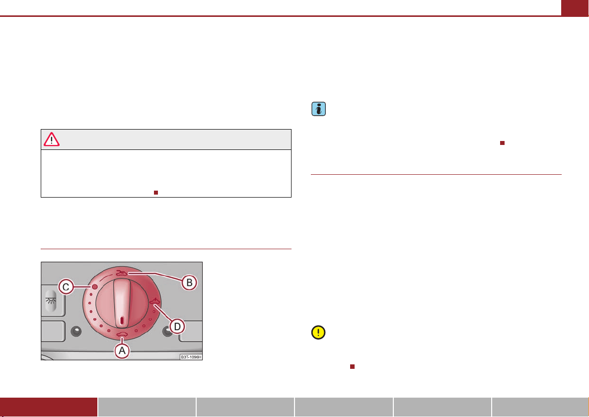
Unlocking and locking 57
A
ACABA
• you must pull the respective switch again in upward direction for approx. 3
seconds.
Operation in winter
Ice accumulating on the surface of the windows during the winter may result in a
greater resistance when closing the windows and the window may stop and go
down several centimetres
It is necessary to put the force limiter out of operation in order to close the window
⇒ page 56, “Force limiter of the power windows”.
WARNING
The system is fitted with a force limiter ⇒ page 56. If there is an obstacle, the
closing process is stopped and the window goes down by several centimeters. You should then take particular care when closing the windows! You
may otherwise suffer severe injuries as a result of getting an arm, for
example, jammed in the window!
Electric sliding/tilting roof*
Description
The sliding/tilting roof is operated by means of the control dial ⇒ fig. 52 and only
functions when the ignition is switched on. The control dial has a number of fixed
positions.
After switching the ignition off, it is still possible to open or close the sliding/tilting
roof for a further 10 minutes. It is no longer possible to operate the sliding/tilting
roof after opening or closing one of the front doors, however.
Note
If the battery has been disconnected and reconnected, it is possible that the
sliding/tilting roof does not close fully. Here you have to set the control dial to the
switch position and press it forward for about 10 seconds.
A
Opening and tilting
Comfort position
– Turn the switch to position ⇒ fig. 52.
Opening roof fully
– Turn the switch to position and hold it in this position (spring-
tensioned position).
Tilting roof
– Turn the switch to position .
The wind noise in the comfort position is less than when the roof is fully opened.
The sun screen is also opened automatically when the roof slides open.
D
Caution
Fig. 52 Control dial for the
power sliding/tilting roof
Using the system Safety Driving Tips General Maintenance Breakdown assistance Technical Data
It may be necessary during winter to remove any ice and snow in the area of the
sliding/tilting roof before opening it in order to prevent damaging the opening
mechanism.
Page 59
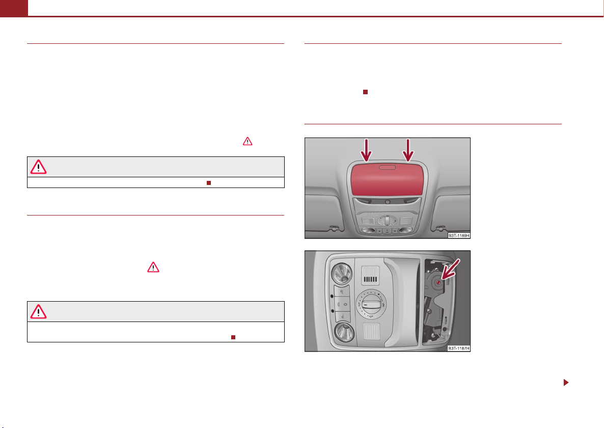
Unlocking and locking58
A
A
Closing
Sliding closed/closing the sliding/tilting roof
– Turn the switch to position ⇒ fig. 52.
Safety closing
The sliding/tilting roof is equipped with an overload protection system. If an
obstacle (e.g. ice) prevents closing, the sliding/tilting roof stops and opens
completely. You can close the sliding/tilting roof completely without overload
protection by pressing the switch to the position ⇒ page 57, fig. 52 at the front
for as long as it takes for the sliding/tilting roof to shut completely ⇒ .
A
A
WARNING
Close the sliding/tilting roof carefully - risk of injury!
Convenience operation
You can also close an open sliding/tilting roof from the outside.
– Keep the lock button on the radio remote control pressed or hold the
key in the lock of the driver's door in the lock position until the
sliding/tilting roof is closed ⇒ .
The closing operation stops when one releases the key or the lock button.
WARNING
Close the sliding/tilting roof carefully - risk of injury! The overload protection system does not function with the convenience closing.
Electric sliding/tilting roof with solar cells*
If there is sufficient bright sunlight, the solar cells on the sliding/tilting roof deliver
power for the fresh air blower. Further information ⇒ page 109.
The operation of the sliding/tilting roof with solar cells is the same as of a normal
sliding/tilting roof.
Emergency operation
Fig. 53 Detail of the headliner: point for positioning
screwdriver
Fig. 54 Detail of the headliner: Emergency operation
You can close and/or open the sliding/tilting roof by hand if the system is
defect.
Page 60

– Position the flat blade of a screwdriver carefully against the rear edge
A
of the cover of the electrical drive ⇒ fig. 53.
– Pull the cover down.
– Insert an Allen key, Group 4, up to the stop into the opening and close
and/or open the sliding/tilting roof ⇒ fig. 54.
– Press on the cover again by first of all inserting the plastic lugs and
then pushing the cover up.
– Have the fault rectified by a specialist workshop.
On vehicles fitted with a storage compartment for spectacles*, this compartment
must be opened before removing the cover for the emergency operation
⇒ page 98.
Note
It is necessary after each emergency operation to move the sliding/tilting roof into
the basic position. Here you have to turn the control dial forward to the switch posi-
A
tion ⇒ page 57, fig. 52 and press for about 10 seconds.
Unlocking and locking 59
Using the system Safety Driving Tips General Maintenance Breakdown assistance Technical Data
Page 61
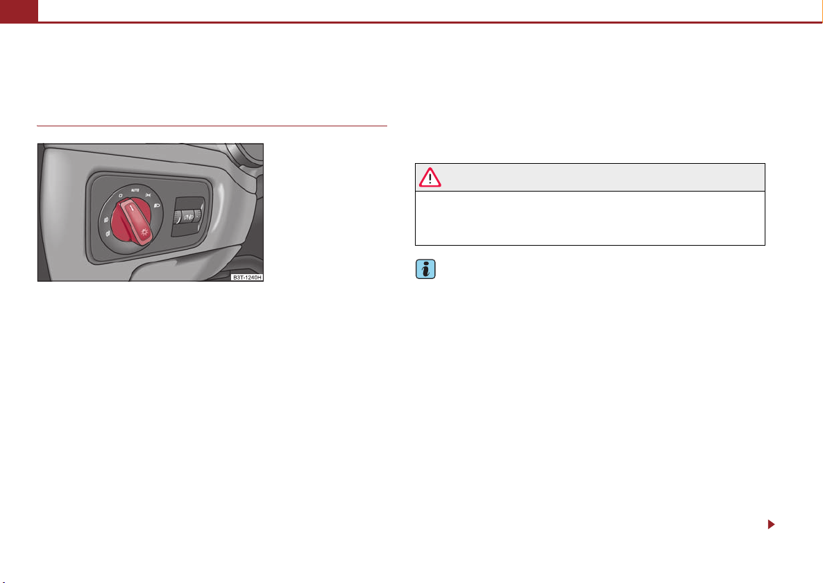
Lights and Visibility60
Lights and Visibility
Lights
Switching lights on and off
Fig. 55 Dash panel: Light
switch
Switching on side lights
– Turn the light switch into position
Switching on the low beam and main beam
– Switch on the ignition.
– Turn the light switch into position
– Press the main beam lever forward in order to switch on the main
beam ⇒ page 67, fig. 61.
Switching off lights (except daylight driving lights)
– Turn the light switch into position°0.
When the parking lights are switched on, the symbol next to the light switch is
illuminated.
.
.
Low beam comes on only if the ignition is switched on. After switching off the ignition, the low beam is switched off automatically and only the side lights come on.
On models fitted with right-hand steering the position of certain switches differs
from that shown in ⇒ fig. 55. The symbols which mark the switch positions are
identical, however.
WARNING
Never drive with side lights on - risk of accident! The side lights are not
bright enough to light up the road sufficiently in front of you or to be seen by
other oncoming traffic. In this case, always switch on the low beam when it
is dark or if visibility is poor.
Note
• An audible warning will sound if you withdraw the ignition key and open the
driver's door when the vehicle lights are still on.
• The acoustic warning signal is switched off over the door contact when the
driver's door is closed (ignition off). The vehicle can be parked with the side lights
on.
• If the car is parked for a lengthy period, we recommend switching off all lights,
or leaving only the parking lights switched on.
• The switching on of the described lights should only be undertaken in accord-
ance with the legal requirements.
• If a fault occurs in the light switch, the low beam comes on automatically
• In the event of cool or humid weather conditions, the headlights can be misted
up from inside.
− The temperature difference between interior and external area of the headlight lenses is decisive.
− When the driving lights are switched on, the light outlet surfaces are free
from mist after a short period. The headlight lenses can possibly mist up at the
border areas.
Page 62
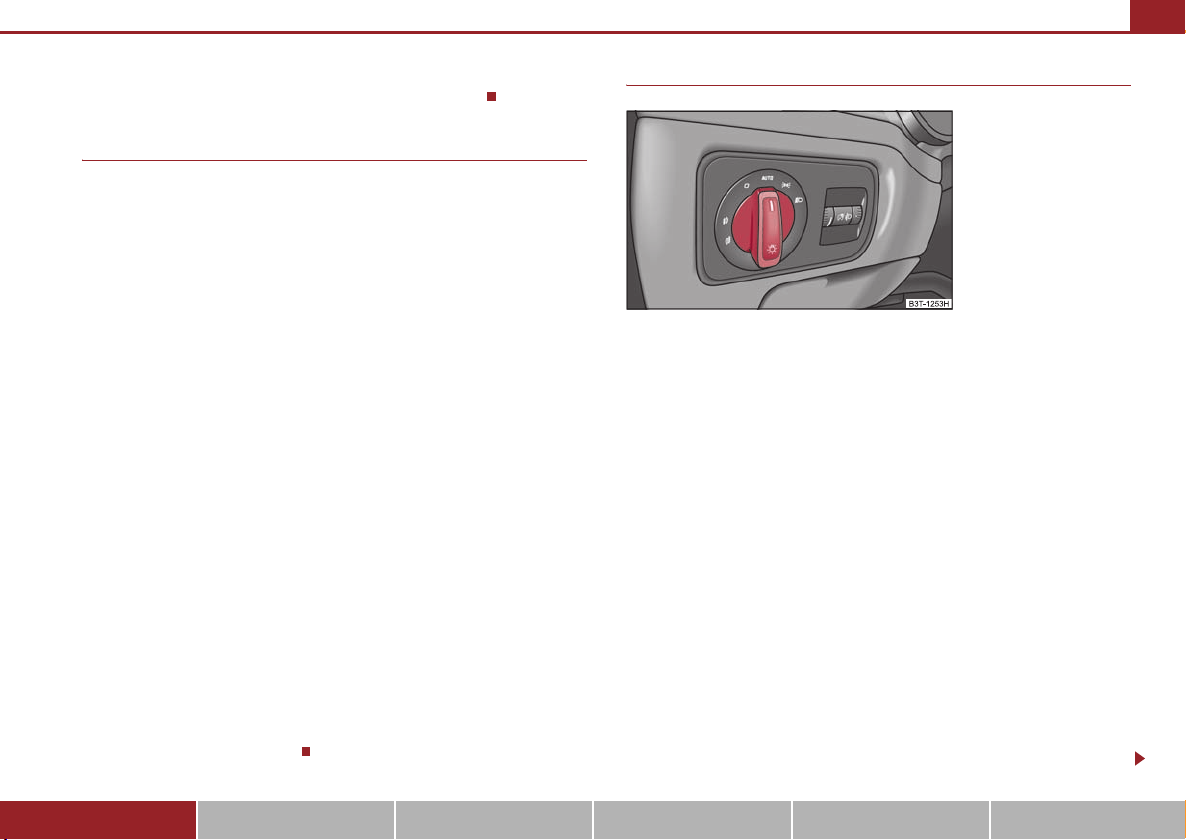
Lights and Visibility 61
− It also concerns reverse light and turn signal lights.
− This mist has no influence on the life of the lighting system.
Daylight driving lights*
In some countries, the national legislation requires that the vehicles are
equipped with the function daylight driving lights.
Switching on daylight driving lights
– Switch on the ignition without turning the light switch out of the posi-
tion 0.
Deactivate function daylight driving lights
– Pull the turn signal light lever towards the steering wheel up to 3
seconds after switching on the ignition and at the same time, slide it to
the bottom and hold it in this position for at least 3 seconds.
Activate function daylight driving lights
– Pull the turn signal light lever towards the steering wheel up to 3
seconds after switching on the ignition and at the same time, slide it to
the top and hold it in this position for at least 3 seconds.
When the daylight driving lights are switched on, also the low beam with reduced
brightness shines together with the side lights (approx. 92 % of the performance).
This contributes to a longer life of the lamps for the low beam.
When the daylight driving lights are switched on, the ill umination of the instrument
cluster is switched off, however, it is switched on in the position when it is dark
and the low beam shines with full brightness (100 % of the performance).
On vehicles fitted with an information display*, you can activate or deactivate in the
menu the function daylight driving lights:
SETUP (Settings)
Lights & Vision (Lights & Vision)
Automatic light control*
Fig. 56 Dash panel: Light
switch
Switching on automatic light control*
– Turn the light switch ⇒ fig. 56 into position
.
Switching off automatic light control*
– Turn the light switch to the position 0,
If the light switch is in the position , the symbol illuminates when the ignition
is switched on next to the light switch. If the low beam is activated with the
light sensor, the symbol illuminates additionally next to the light switch.
If the light comes on automatically, the side lights and low beam as well as licence
plate light light up at the same time.
If the automatic light control is switched on, the light is regulated with the light
sensor in the rear mirror holder. If the light intensity drops below the set value, e.g
when driving during the day into a tunnel, the low beam and the side lights as well
as the licence plate light come on automatically. If the light intensity increases
again, the lights switch off automatically.
Motorway lights
If the automatic light control has been switched on and the vehicle speed is over
140 km/h for at least 10 seconds, the side lights and low beam are switched on
automatically.
or .
Using the system Safety Driving Tips General Maintenance Breakdown assistance Technical Data
Page 63
Lights and Visibility62
If the vehicle speed is below 65 km/h for at least 2 minutes, the lights are switched
off.
Rain lights
If you move the windshield wiper lever in the position slow wipe for more than 5
seconds, the side lights and low beam are automatically switched on. The light is
switched off when the windshield wiper lever is no longer than 4 minutes in the
position for slow or intermittent wipe.
If you switch on the windscreen wipe in the operation rain sensor* for longer than
10 seconds or in the operation permanent wipe (position 2 or 3) ⇒ page 73
switching on for longer than 15 seconds, the side lights and low beam are switched
on automatically. The light switches off if the windscreen wipe is in operation rain
sensor* for more than 4 minutes or is not switched on in the operation permanent
wipe.
WARNING
The automatic light control only operates as a support. The driver is not
released from his responsibility to inspect the light and if necessary to s witch
on the light depending on the light conditions. The light sensor cannot
detect for example rain or snow. For these conditions we recommend to
switch on the low beam !
Note
• Do not affix any stickers in front of the light sensor, so that you do not impair its
function or put it out of operation.
• The same principles as for using the automatic light control also apply to the
light which is switched on manually ⇒ page 60.
Switching on Coming Home Function
– The light switch is in the position automatic driving lamp control
and the low beam illuminates.
– Switch off the ignition.
– After opening the driver's door, the function Coming Home is
switched on.
– Close all the doors and the boot lid and lock the vehicle. After a short
time, switch all lights off.
Depending on equipment fitted the function Coming Home switches on the
following lights:
• Parking lights,
• Low be am,
• Entry lighting in the exterior mirrors,
• Licence plate light.
Coming Home Function
The lights go out 10 seconds after closing all the doors and the boot lid.
If a door or the boot lid remains open, the lights go out 60 seconds after switching
off the ignition.
On vehicles fitted with automatic driving lamp control you can also switch the light
switch in the position . The function Coming Home is controlled with the light
sensor in the mount of the interior rear mirror. If the light intensity is higher than the
set value of the light sensor, the Coming Home Function is not switched on after
switching off the ignition.
Coming Home Function
The function makes it possible to switch on the lights in the darkness for
a short time after leaving the vehicle.
Note
• If the Coming Home Function is switched on constantly, the battery will be
heavily discharged particularly in short-haul traffic.
• The switching on of the described lights should only be undertaken in accord-
ance with the legal requirements.
Page 64
Lights and Visibility 63
• You can change the illumination period for the Coming Home Function by
means of the information display*.
Leaving Home Function
This function makes it possible to switch on the lights when approaching
the vehicle.
Switching on Leaving Home Function
– Unlock the vehicle with the radio remote control - the lights come on.
Depending on equipment fitted the function Leaving Home switches on the
following lights:
• Parking lights,
• Low beam,
• Entry lighting in the exterior mirrors,
• Licence plate light.
Leaving Home Function
The function Leaving Home is controlled with the light sensor in the mount of the
interior rear mirror. If the light intensity is higher than the set value of the light
sensor, the Leaving Home Function is not switched on after unlocking the vehicle
with the radio remote control.
After unlocking the vehicle with the radio remote control, the lights come on for 30
seconds. The Leaving Home Function is also switched off after the ignition is
switched on and after locking the vehicle.
If no door is opened within 30 seconds, the lights go out and the vehicle is locked
automatically.
Note
• If the Leaving Home Function is switched on constantly, the battery will be
heavily discharged particularly in short-haul traffic.
• The switching on of the described lights should only be undertaken in accord-
ance with the legal requirements.
• You can change the illumination period for the Leaving Home Function by
means of the information display*.
Adaptive headlights (AHL)*
Switch on Adaptive headlights (AHL)*
– Turn the light switch ⇒ page 61, fig. 56 into position
The outer illumination switches on if:
.
• the light sensor recognizes the low light intensity,
• no reverse gear is engaged,
• the operation “tourist light” is not switched on.
The light sensor switches on the full outer illumination at low light intensity.
System AHL* makes it possible to change the length and width of illumination of
the headlight. The length and width of illumination changes automatically in relation to the vehicle speed and the use of the windscreen wiper.
System AHL* operates in the following modes.
Mode out of town
The mode “out of town” is a basic mode. The dispersion of the cone of light in front
of the vehicle is similar to the lo w beam. The mode is active if none of the following
modes are active.
Mode rain
In the mode “rain” the dispersion of the cone of light in front of the vehicle is wider
and the width of illumination is shorter, so that during bad weather (rain) the
dazzling of the oncoming drivers can be reduced. The mode is activated at speeds
of 15 - 70 km/h and if the windscreen wipers continuously operate for a period of
time longer than 2 minutes. The mode is deactivated when dropping below or
exceeding the set speed limit or if the windscreen wipers have been switched off for
a period of time longer than 8 minutes.
Using the system Safety Driving Tips General Maintenance Breakdown assistance Technical Data
Page 65

Lights and Visibility64
A
Mode city
In the mode “city”, the dispersion of the cone of light in front of the vehicle is wider
and the width of illumination is shorter. It has as an aim to illuminate the adjacent
footpaths, crossings, pedestrian crossings etc. The mode is active at speeds of 15 50 km/h.
Mode motorway
In the mode “motorway” the dispersion of the cone of light is so widespread, that it
illuminates also the left (and right) 7) lane of the motorway, so that the driver can
react in time to an obstacle or any other danger. The mode is activated stepwise as
of a speed of 90 km/h. It gains its greatest effectiveness at speeds above 120 km/h.
Tourist light
This mode makes it possible to drive in countries with opposing traffic system,
driving on the left/right, without dazzling the oncoming vehicles. When the mode
“tourist light” is active, the above mentioned modes and the side to side swivel of
the headlight is deactivated.
The mode “tourist light” is activa ted / deactivated via the information display* in the
menu:
SETUP (Settings)
Tra vel mode
Off
On
Cornering lights
The cornering lights are used to illuminate the curves by means of the cone of light
swiveling together with the front headlight with Xenon lights*. This function is
active when the speed of the car increases to more than 10km/h.
The swiveling function of the headlights can be switched off / on via the menu point
Assistant in the main menu of the Information display* ⇒ page 27.
7)
It is valid for vehicles which are designed for driving on the left.
Note
• The AHL system* complements the functions of the fog lights with the function
“Corner” ⇒ page 64 and the function of the dynamic headlight beam range*.
• The System AHL* is solely delivered with Bi-Xenon gas discharge bulbs for low
beam and main beam lights.
Fog lights
Fig. 57 Dash panel: Light
switch
Switching on the fog lights
– First of all turn the light switch into position
– Pull the light switch into position .
The rear fog light warning light ⇒ page 33 lights up in the instrument cluster
when the fog light is switched off.
1
Fog lights with the function “Corner”*
The fog lights with the function “Corner” improve the illumination of
areas close to the vehicle when turning, parking etc.
The fog lights with the function “Corner” are regulated according to the steering
angle or after switching on the turn signal light8) in the following circumstances:
or ⇒ fig. 57.
Page 66
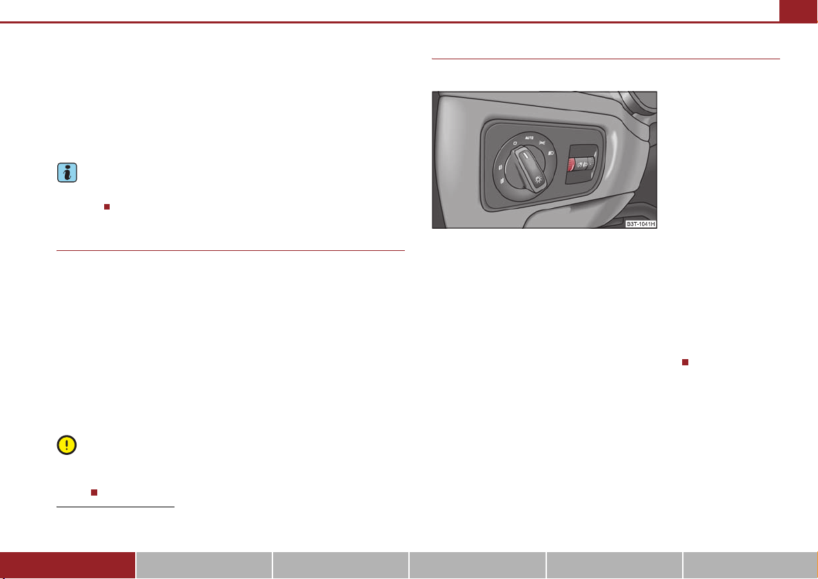
Lights and Visibility 65
A
• the vehicle is stationary and the engine is running or it moves with a speed of
maximum 40 km/h,
• the daylight driving lights are not switched on,
• the low beam is switched on or the light switch is in the position and the
intensity of the ambient light causes the low beam to be switched on,
• the fog lights are not switched on,
• no reverse gear is engaged.
Note
If you engage the reverse gear during the active function “Corner”, both fog lights
illuminate.
Rear fog light
Switching on the rear fog light
– First of all turn the light switch into position
fig. 57.
– Pull the switch into position .
The rear fog light warning light ⇒ page 33 lights up in the instrument cluster
when the fog light is switched off.
Only the rear fog light of the trailer lights up automatically when you are towing a
trailer using a factory-fitted towing device which is fitted with the rear fog light.
The rear fog light is located in the rear light array on the driver's side.
2
or ⇒ page 64,
Instrument lighting
You can adjust the brightness of the instrument lighting.
Fig. 58 Dash panel: Instrument lighting
Instrument lighting
– Switch on the light.
– Turn the control dial ⇒ fig. 58 to the desired intensity of the instru-
ment lighting.
For the information display* ⇒ page 26 the intensity of the lighting is automatically
set. It is only possible to adjust the instrument lighting with the control dial if the
light intensity drops below the set value of the light sensor.
Caution
The rear fog light should only be switched on if visibility is particularly poor
(conform with any varying legal provisions) to avoid dazzling vehicles behind your
vehicle.
8)
If both switch on versions are conflicting, for example if the steering wheel is turned to the
left and the right turn signal light is switched on, the turn signal light has the higher priority.
Using the system Safety Driving Tips General Maintenance Breakdown assistance Technical Data
Page 67
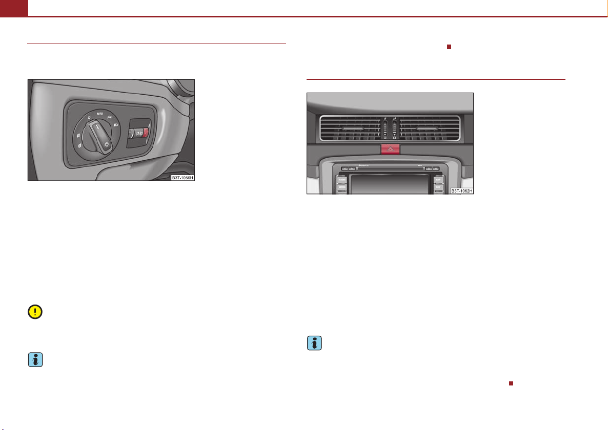
Lights and Visibility66
A
A
A2A
Headlamp range adjustment*
Once the low beam is switched on you can then adapt the range of
the headlights to the load of the vehicle.
Fig. 59 Dash panel: Lights
and Visibility
– Turn the control dial ⇒ fig. 59 until you have adjusted the low beam
so that oncoming traffic is not dazzled.
Settings
The positions correspond approximately to the following vehicle loads:
-
Front seats occupied, luggage compartment empty.
1
All seats occupied, luggage compartment empty.
All seats occupied, luggage compartment laden.
3
Driver seat occupied, luggage compartment laden.
Caution
Set the headlight beam adjustment in such a way as to avoid dazzling oncoming
traffic.
Note
The Bi-Xenon bulbs* adapt automatically to the load and driving state of the vehicle
(e.g. speed, accelerating, braking) when the ignition is switched on and when
driving. Vehicles which are not equipped with Bi-Xenon bulbs* do not have a
manual headlight range adjustment control.
Switch for hazard warning lights
Fig. 60 Dash panel: Switch
for hazard warning lights
–Press switch ⇒ fig. 60 to switch the hazard warning light system on
or off.
All the turn signal lights on the vehicle flash at the same time when the hazard
warning light system is switched on. The indicator light for the turn signals and the
indicator light in the switch also flash at the same time. You can also switch on the
hazard warning light system if the ignition is switched off.
The hazard warning light system is switched on automatically if an airbag is
deployed in the event of an accident.
Please comply with any legal requirements when using the hazard warning light
system.
Note
Switch on the hazard warning light system if, for example:
• you encounter traffic congestion,
• your vehicle breaks down or an emergency situation occurs.
Page 68

Lights and Visibility 67
The turn signal and main beam lever
The parking lights and headlight flasher are also switched on and off
using the turn signal and main beam lever.
Fig. 61 Turn signal and main
beam lever
The turn signal and main beam lever perform the following functions:
and left turn signal light
Right
– Push the lever upwards or downwards ⇒ fig. 61.
– If you only wish to flash three times (the so-called convenience turn
signal), push the lever briefly up to the upper or lower pressure point
and release it. This function can be activated/deactivated in the information display* ⇒ page 30.
– Turn signal for changing lanes - in order to only flash briefly, move the
lever up or down to the pressure point and hold it in this position.
Main beam
– Switch on the low beam.
– Push the lever forwards.
– Pull the lever back into the initial position in order to switch the main
beam off again.
Headlight flasher
– Pull the lever towards the steering wheel (spring-tensioned position)
- the main beam and warning light
on.
Parking light
– Switch off the ignition.
– Push the lever up or down - the right-hand or left-hand parking light
is switched on.
Information concerning the function of the lights.
in the instrument cluster come
• The turn signal system only operates when the ignition is switched on. The
corresponding indicator light or in the instrument cluster also flashes.
• The turn signal is automatically cancelled after negotiating a curve.
• The indicator lig ht flashes at twice its normal rate if a bulb of the turn signal light
fails.
• The side light and rear light on the appropriate side of the vehicle are switched
on when the parking light is selected. The parking light only operates if the ignition
is switched off.
Caution
Use main beam or the headlight flasher only if this does not risk dazzling other road
users.
Note
• If you have switched on the right or left turn signal light and you switch off the
ignition, the parking light is not automatically switched on.
• Use only in accordance with the legal requirements the described lighting and
signal systems.
Using the system Safety Driving Tips General Maintenance Breakdown assistance Technical Data
Page 69

Lights and Visibility68
Interior lighting
Front interior lighting and lighting of storage compartment on
front passenger side
Fig. 62 Detail of the headliner: front interior lighting
Fig. 63 Detail of the headliner: front interior lighting
Switching the interior light on
– Press the switch at the point of the symbol
Switching the interior light off
– Press the switch at the point of the symbol O.
⇒ fig. 62 or ⇒ fig. 63.
Door contact setting
– Position the switch into middle position. On vehicles without interior
monitor*, the middle position is marked with a symbol
⇒ fig. 62.
Lighting of storage compartment on the front passenger side
– When opening the flap of the storage compartment on the front
passenger side the lighting in the storage compartment comes on.
– The light switches on automatically when the parking light is switched
on and goes out when the flap is closed.
The interior light comes on as soon as you unlock the car or open a door or when
the ignition key has been removed. The light goes out again about 30 seconds after
all the doors have been closed. The interior lighting is switched off when you lock
the car or switch the ignition on. This only applies when the switch for the corresponding interior lights is standing n the door contact setting.
The interior lighting goes off after about 10 minutes when a door has been left open
in order to avoid discharging the battery of the vehicle.
If the switch is in the position (permanent lights), the inter ior lighting goes off at
the latest after 10 minutes in order to avoid discharging the battery of the vehicle.
Two LEDs are integrated in the interior lighting, which illuminates the shift lever and
the middle of the dash panel. They are switched on automatically when switching
on the parking light.
In addition, the lighting of the door handle is switched on after the ignition is
switched on when the side lights are switched on.
Together with the front interior light, the rear interior light is simultaniously
switched on or off.
Note
We recommend having these bulbs replaced by a specialist garage.
Page 70

Lights and Visibility 69
Front reading lights
Fig. 64 Detail of the headliner: Front reading lights
Fig. 65 Detail of the headliner: Front reading lights
with integrated interior
monitor
Front reading lights
– You switch on or off the reading light on the right or left by pressing the
switch
⇒ fig. 64 or ⇒ fig. 65.
Interior lighting and rear reading lights
Fig. 66 Detail of the headliner: Interior lighting and
rear re ading lig hts
Interior lighting
– The rear interior lighting is operated together with the front interior
lighting ⇒ page 68.
Reading lights
– You switch on or off the reading light on the right or left by pressing the
switch
⇒ fig. 66.
Door warning light
Fig. 67 Front door: Warning
light
Using the system Safety Driving Tips General Maintenance Breakdown assistance Technical Data
Page 71

Lights and Visibility70
The warning light is located in the door trim panel below ⇒ page 69, fig. 67.
The warning light goes on every time the door is opened. The light goes out about
10 minutes after opening the door in order to avoid discharging the battery of the
vehicle.
Luggage compartment light
The lighting comes on automatically when the boot lid is opened. The luggage
compartment lighting will switch off again automatically if the boot lid remains
open for more than about 30 minutes.
Entry lighting*
The lighting is positioned on the bottom edge of the exterior mirror.
The light beam is directed towards the entry area of the front door.
The light comes on after the doors have been locked or on opening the boot lid. The
light goes out after switching on the ignition or up to 30 seconds after closing all the
doors, the bonnet and the boot lid.
If a door, the bonnet or the boot lid remains open, the light goes out within 2
minutes if the ignition is switched off.
WARNING
If the entry light comes on, do not touch its cover - risk of burns!
Visibility
Windscreen and rear window heater
Fig. 68 Switch for windscreen heater
Fig. 69 Switch for rear
window heater
Windscreen heater*
– You can switch the windscreen heater on or off by pressing the switch
⇒ fig. 68 - the indicator light in the switch comes on or goes out.
Page 72

Lights and Visibility 71
A
A
Rear window heater
– You can switch the rear window heater on or off by pressing the switch
⇒ page 70, fig. 69 - the indicator light in the switch comes on or
goes out.
The windscreen and rear window heater only operates when the engine is running.
The windscreen and rear window heater switches off automatically after 10
minutes.
For the sake of the environment
As soon as the window is de-iced or free from mist, the heating should be switched
off. The reduced current consumption will have a favourable effect on fuel
economy ⇒ page 205, “Saving electricity”.
Note
• If the on-board voltage drops, the windscreen or rear window heater is
switched off automatically, in order to provide sufficient electrical energy for the
engine control.
• The position and the shape of the switch for rear window heater can differ
depending on the equipment installed in the vehicle.
Sun visors
Fig. 70 Sun visor: swivelling
out
You can pull the sun visor for the driver or front passenger out of the fixture and
swivel it toward the door in the direction of the arrow ⇒ fig. 70.
The vanity mirrors in the sun visors are provided with covers. When you slide open
the cover in the direction of the arrow , the vanity mirror lighting in the headliner
switches on automatically. It switches off again when you slide the cover closed or
when you raise the sun visor.
2
1
WARNING
The sun visors must not be swivelled to the side windows into the deployment area of the head airbags if any objects, such as ball-point pens etc. are
attached to them. This might result in injuries to the occupants if the head
airbag is deployed.
Using the system Safety Driving Tips General Maintenance Breakdown assistance Technical Data
Page 73

Lights and Visibility72
AAABABA
AAA
Sun screen*
Fig. 71 Unroll the sun screen
The sun screen is located in the lower part of the luggage compartment
cover.
Pulling out
– Pull the sun screen at the handle and hang it in the magnetic
brackets ⇒ fig. 71.
Fold ing
– Take the sun screen out of the magnetic brackets and hold it at the
A
handle so that it can roll up slowly and without damage into the
housing on the luggage compartment cover.
Note
Do not place any objects which can react sensitively to influences of magnetic fields
(watches, electronics etc.) in the immediate area of the magneti c brackets. They can
be damaged by the magnetic field.
Sun screen in the rear doors*
Fig. 72 Rear door: Sun
screen
Pulling out
– Pull the sun screen at the handle ⇒ fig. 72 and hang it in the
bracket on the top edge of the door.
Fold ing
– Take the sun screen out at the handle and hold it in s uch a way that
A
it can roll up slowly and without damage.
Page 74
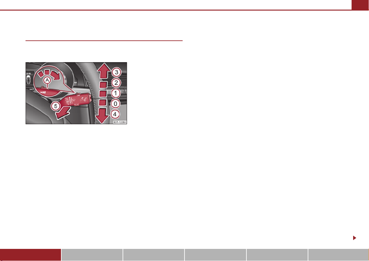
Lights and Visibility 73
A4A
AAA
A3A
A1AAA
Windshield wiper and wash system
Windshield wiper
You can operate the windscreen wipers and automatic wipe/wash
using the windscreen wiper lever.
Fig. 73 Windscreen wiper
lever
The windscreen wiper lever ⇒ fig. 73 has the following positions:
Finger-operated wiping
– If you wish to wipe the windscreen only briefly, push the lever into the
sprung position . If you hold the lever in the lower position for more
than 1 second, the wiper wipes faster.
Intermittent wiping
– Position the lever up into position .
– Set with the switch the desired break between the individual wiper
strokes
Slow wipe
– Position the lever up into position .
1
2
Fas t wipe
– Position the lever up into position .
Automatic wipe/wash for windscreen
– Pull the lever towards the steering wheel into sprung position , the
5
wash system sprays immediately, the windscreen wiper starts wiping
a little later. The wash system and the windscreen wiper operate
simultaneously at a speed of more than 120 km/h.
– Release the lever. The windscreen wash system stops and the wiper
continues for another 3 - 4 wiper strokes (depending on the period of
spraying of the windscreen). At a speed of more than 2 km/h, the wiper
wipes once again* 5 seconds after the last wiper stroke in order to
wipe the last drops from the windscreen. This function can be activated/deactivated by a specialist garage.
Rain sensor*
– Move the lever into position .
– You can set the sensitivity of the sensor individually with switch .
Switching windscreen wipers off
– Move the lever back into its home position .
After the windscreen wiper switches off each time or the ignition switches off for
the third time, the position of the windscreen wiper changes, this counteracts an
early fatigue of the wiper rubbers.
The windscreen wipers and the wash system only operate if the ignition is switched
on and the bonnet is closed.
If the intermittent wipe is switched on, the intervals are also controlled depending
on speed.
The rain sensor* automatically regulates the break between the individual wiper
strokes depending on the intensity of the rain.
The windscreen washer nozzles are heated* when the ignition is switched on.
0
Using the system Safety Driving Tips General Maintenance Breakdown assistance Technical Data
Page 75
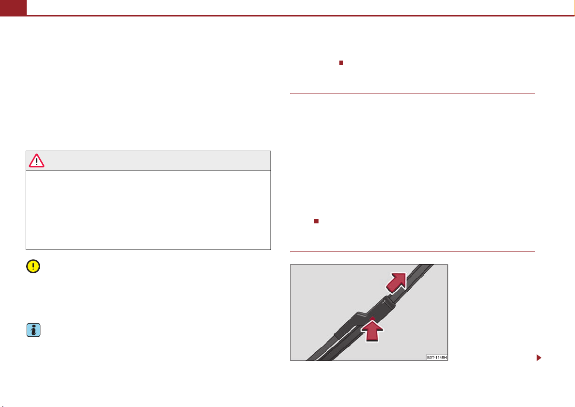
Lights and Visibility74
A2A3A
Top up with wash liquid ⇒ page 234.
Winter position
If the windscreen wipers are in rest position, they cannot be folded out from the
windscreen. For this reason we recommend adjusting the windscreen wipers in
winter so that they can be folded out from the windscreen easily. You can set this
rest position as follows:
• Switch on the windscreen wipers.
• Switch off the ignition. The windscreen wipers remain in the position in which
they were when switching off the ignition.
You can also use the service position as a winter position.
WARNING
• Properly maintained windscreen wiper blades are essential for clear visi-
bility and safe driving ⇒ page 74.
• Do not use the windscreen washer system at low temperatures, without
heating the windscreen beforehand. Otherwise the window cleaner could
freeze on the windscreen and restrict the view to the front.
• The rain sensor only operates as a support. The driver is not released
from the responsibility to set the function of the windscreen wipers manually depending on the visibility conditions.
Caution
In frosty weather, please first of all check whether the windscreen wiper blades are
not frozen to the windscreen before switching them on. Switching on windscreen
wipers when the blades are frozen to the windscreen may result in damage both to
the blades and the motor of the windscreen wipers!
• If there is an obstacle on the windscreen, the wiper will try to push away the
obstacle. If the obstacle continues to block the wiper, the wiper stops after 5 cycles,
in order to avoid a damage to the wiper. Remove the obstacle and and switch on
the wiper again.
Headlight cleaning system*
The headlights are being cleaned after the windscreen has been sprayed for the first
time and fifth time, the low beam or main beam are switched on and the windscreen wiper lever was held in the position ⇒ page 73, fig. 73 for about 1
second.
The headlight washer nozzles are moved forward out of the bumper by the water
pressure for cleaning the headlights.
You should remove stubborn dirt (such as insect residues) from the headlight
lenses at regular intervals, for example when refuelling. Please refer to the following
guidelines.
You should remove any snow from the fixtures of the washer nozzles and clear ice
in winter with a de-icing spray in order to ensure proper operation of the cleaning
system.
Replacing wiper blades for the windscreen wipers
5
Note
• If the slower or the faster wiper setting is switched on ⇒ page 73, fig. 73
and the vehicle speed decreases to below 4 km/h, the lower wiper step is switched
on automatically. At a speed increase of more than 8 km/h the previous wiper
setting is established again.
Fig. 74 Wiper blade for the
windscreen wiper
Page 76
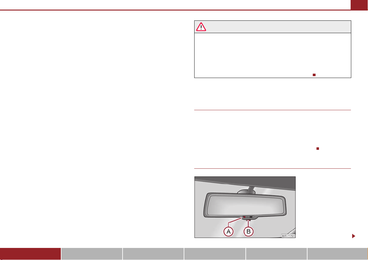
Lights and Visibility 75
A
One cannot fold out the wiper arms in the rest position from the windscreen. Before replacing the wiper arms you must put them into the
service position.
Service position for changing wiper blades
– Close the bonnet.
– Switch the ignition on and then again off.
– Then press the windscreen wiper lever in the position ⇒ page 73,
4
fig. 73 within 10 seconds - the wiper arms move into the service posi-
tion.
Taking off the wiper blade
– Fold windscreen wiper arm away from the windscreen.
– Press the locking button, in order to unlock the wiper blade and pull
off in the direction of arrow ⇒ page 74, fig. 74.
Attaching a wiper blade
– Push the wiper blade until it locks up to the stop.
– Check whether the wiper blade is correctly attached.
– Fold the windscreen wiper arm back onto the windscreen.
The wiper arms move back into the rest position - after switching on the ignition
and after changing the position of the window wiper lever or when driving at a
speed greater than 6°km/h.
Wiper blades in proper condition are essential to obtain good visibility. Wiper
blades should not be allowed to become dirtied by dust, insect remains and
preserving wax.
Juddering or smearing of the wiper blades could then be due to wax residues left
on the windscreen by vehicle washing in automatic vehicle wash systems. It is
therefore important to degrease the lips of the wiper blades after every pass
through an automatic vehicle wash system.
WARNING
• If the windscreen wipers are handled carelessly, there is a risk of damage
to the windscreen.
• You should clean the wiper blades regularly with a windscreen cleaner in
order to avoid any smears. Clean a wiper blade with a sponge or cloth if it is
very dirty, for example from insect residues.
• Replace the wiper blades once or twice a year for safety reasons. These
can be bought from an authorised Škoda Service Partner.
Rear-view mirror
Manual dimming interior rear-view mirror
Basic setting
– Pull the lever on the bottom edge of the mirror forward.
Dimming mirror
– Pull the lever on the bottom edge of the mirror back.
Automatic dimming interior mirror*
Fig. 75 Automatic dimming
interior mirror
Using the system Safety Driving Tips General Maintenance Breakdown assistance Technical Data
Page 77
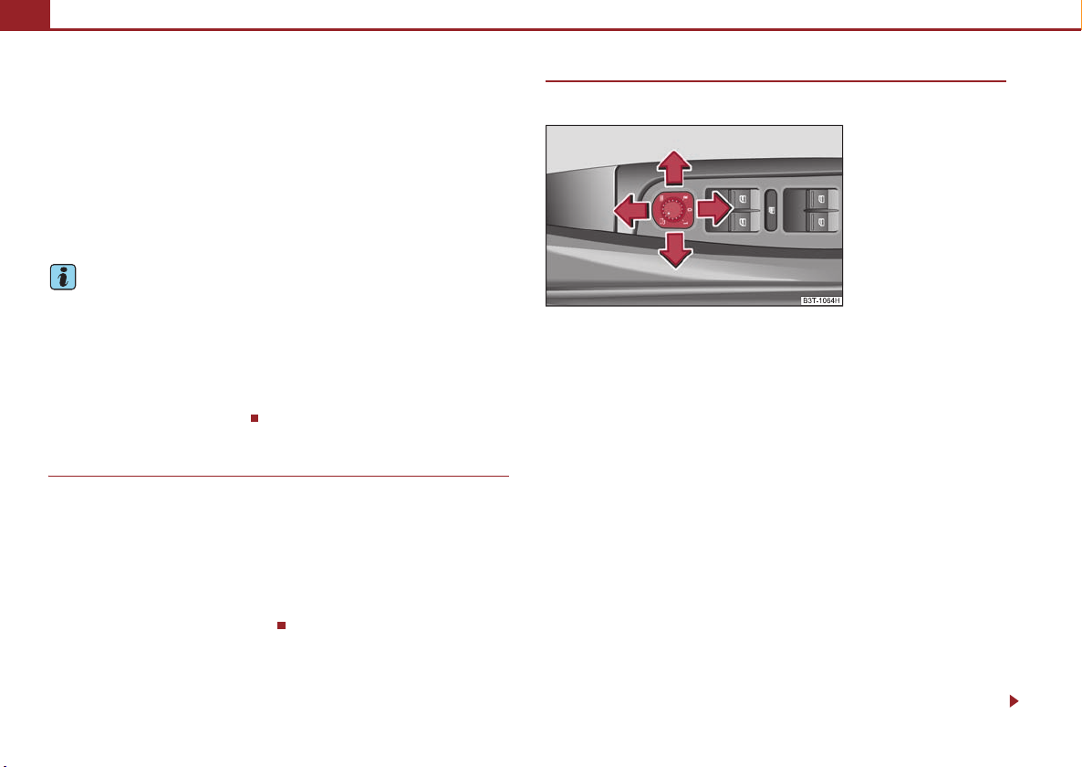
Lights and Visibility76
ABAAABA
Switching on the automatic dimming
– Press the button - the warning light lights up ⇒ page 75, fig. 75.
Switching off the automatic dimming
– Press again the button - the warning light goes out .
If the automatic dimming is switched on, the mirror dims automatically
depending on the light striking the mirror from the rear. The mirror has no lever on
the bottom edge of the mirror. When the interior lights are switched on or the
reverse gear is engaged, the mirror always moves back into the basic position.
Note
A
• Automatic mirror dimming operates only properly if the sun screen* for the rear
window in the housing on the luggage compartment cover is not in use or the light
striking the interior rear-view mirror is not affected by other objects.
• Do not affix any st ickers in front of the light sensor, so that you do not impair the
automatic dimming function or put it out of operation.
• If you switch off the automatic dimming interior rear-view mirror, also the exte-
rior mirror dimming is switched off.
Exterior mirror with entry lighting*
The lighting is positioned on the bottom edge of the exterior mirror.
The light beam is aimed at the entry area of the front doors after the car is unlocked.
The light comes on after the doors have been locked or on opening the front door.
The lighting goes out about 30 seconds after the doors are closed or if the ignition
is switched on.
If the doors remain open, the lighting goes out automatically after about 10 minutes
provided the ignition is not switched on.
Exterior mirror
You can adjust the exterior mirrors electrically*.
Fig. 76 Inner part of door:
Rotary knob
The exterior mirror heater only operates when the engine is running and
up to an outside temperature of +20 °C.
Heating of the external mirror
– Turn the rotary knob to position
Adjusting left and right exterior mirrors simultaneously
– Turn the rotary knob to position
is identical to the movement of the rotary knob.
Adjusting the right-hand exterior mirror
– Turn the rotary knob to position
surface is identical to the movement of the rotary knob.
Switching off operating control
– Turn the rotary knob to position
⇒ fig. 76.
. The movement of the mirror surface
. The movement of the mirror
.
Folding in both exterior mirrors*
– Turn the rotary knob to position
.
Page 78
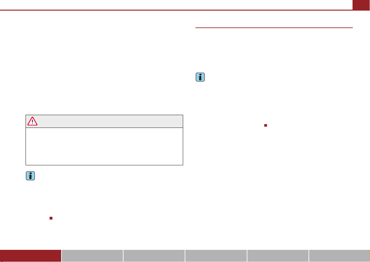
Lights and Visibility 77
A
Lowerable exterior mirror* with the aid of the key for remote control
– If all the windows are closed, press the unlock button on the radio
3
remote control ⇒ page 51, fig. 48 for approx. 2 seconds.
Tilting surface of front passenger exterior mirror*
When the rotary knob is in position ⇒ page 76, fig. 76 and the reverse gear is
engaged, the surface of the mirror tilts down slightly. This provides an aid in seeing
the kerb of the pavement when parking the car.
The mirror returns into its initial position, after the rotary knob is moved out of the
position and put into another position or if the speed is more than 15 km/h.
Memory for exterior mirrors*
On vehicles fitted with a memory for the dr iver seat, the relevant setting of the exterior mirror is also stored automatically when the seat position is stored.
WARNING
• Convex (curved outward) or spherical (differently curved) exterior
mirrors increase the vision field. They do, however, make objects appear
smaller in the mirror. These mirrors are only of limited use, therefore, for
estimating distances to the following vehicles.
• Use whenever possible the interior rear mirror, for estimating the
distances to the following vehicles.
Note
• Do not touch the surfaces of the exterior mirrors if the exterior mirror heater is
switched on.
• You can set the exterior mirrors by hand, if the power setting function fails at any
time by pressing on the edge of the mirror surface.
• Contact your specialist garage if a fault exists with the power setting of the exte-
rior mirrors.
Automatic dimming exterior mirror*
The exterior mirrors are dimmed together with the interior mirror. If the automatic
dimming is switched on, the mirror dims automatically depending on the light
striking the mirror from the rear.
When the interior lights are switched on or the reverse gear is engaged, the mirror
always moves back into the basic position (not dimmed).
Note
• Automatic mirror dimming operates only properly if the sun screen* for the rear
window is not in use or the light striking the rear of the interior rear-view mirror is
not affected by other objects.
• Do not affix any stickers in front of the light sensor, so that you do no t impair the
automatic dimming function or put it out of operation.
• If you switch off the automatic dimming interior rear-view mirror, also the exte-
rior mirror dimming is switched off.
Using the system Safety Driving Tips General Maintenance Breakdown assistance Technical Data
Page 79
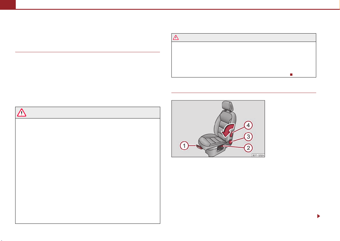
Seats and Stowage78
A
A1A
Seats and Stowage
Front seats
Basic information
The front seats have a wide range of different settings and can thus be matched to
the physical characteristics of the driver and front passenger. Correct adjustment of
the seats is particularly important for:
• safely and quickly reaching the controls,
• a relaxed, fatigue-free body position,
• achieving the maximum protection offered by the seat belts and the airbag
system.
WARNING
• Never transport more occupants than the maximum seating in the
vehicle.
• Each occupant must correctly fasten the seat belt belonging to the seat.
Children must be fastened ⇒ page 185, “Transporting children safely” with
a suitable restraint system.
• The front seats and the head restraints must always be adjusted to match
the body size of the seat occupant as well as the seat belts must always be
correctly fastened in order to provide an optimal protection for you and your
occupants.
• Always keep your feet in the footwell when the car is being driven - never
place your feet on the instrument panel, out of the window or on the
surfaces of the seats. This is particularly important for the front seat
passenger. You will be exposed to increased risk of injury if it becomes
necessary to apply the brake or in the event of an accident. If an airbag is
deployed, you may suffer fatal injuries when adopting an incorrect seated
position!
• It is important for the driver and front passenger to maintain a distance
of at least 25 cm from the steering wheel or dash panel. Not maintaining this
WARNING (continued )
min imum dista nce w ill me an th at the airb ag sys tem wi ll no t be a ble to properly protect you - hazard! The front seats and the head restraints must
always also be correctly adjusted to match the body size of the occupant.
• Ensure that there are no objects in the footwell as any objects may get
behind the pedals during a driving or braking manoeuvre. You would then
no longer be able to operate the clutch, to brake or accelerate.
Adjusting the front seats
Fig. 77 Controls at seat
Adjusting a seat in a forward/back direction
– Pull the lever ⇒ fig. 77 up and push the seat into the desired posi-
tion.
– Release the lever and push the seat further until the lock is heard
to engage.
Adjusting height of seat
– Lift the seat if required by pulling or pumping lever upwards.
1
2
Page 80

Seats and Stowage 79
A2A3A
ABA
A
– Lower the seat if required by pushing or pumping lever down-
wards.
Adjust the angle of the seat backrest
– Relieve any pressure on the seat backrest (do not lean on it) and turn
the handwheel ⇒ page 78, fig. 77 to adjust the desired angle of the
backrest.
Adjusting lumbar support
– Turn the lever until you have set the most comfortable curvature
4
of the seat upholstery in the area of your spine.
The driver's seat should be adjusted in such a way that the pedals can be pressed
to the floor with slightly bent legs.
The seat backrest on the driver's seat should be adjusted in such a way that the
upper point of the steering wheel can be easily reached with slightly bent arms.
WARNING
• Only adjust the driver seat when the vehicle is stationary - risk of injury!
• Take care when adjusting the seat! Adjusting the seat without care can
lead to bruises or injuries.
• The seat backrests must not be angled too far back when driving other-
wise this will affect proper operation of the seat belts and of the airbag
system - risk of injury!
Adjusting front seats electrically*
Adjusting seats
Fig. 78 Side view: Controls
for adjusting the seat
Fig. 79 Side view: Seat
setting switch
Adopt the correct seated position before setting ⇒ page 78.
Adjusting a seat in a forward/back direction
– Press the switch ⇒ fig. 78 forwards or backwards ⇒ fig. 79.
1
Set the height of the seat
– Press the switch ⇒ fig. 78 upwards or downwards.
Using the system Safety Driving Tips General Maintenance Breakdown assistance Technical Data
B
Page 81
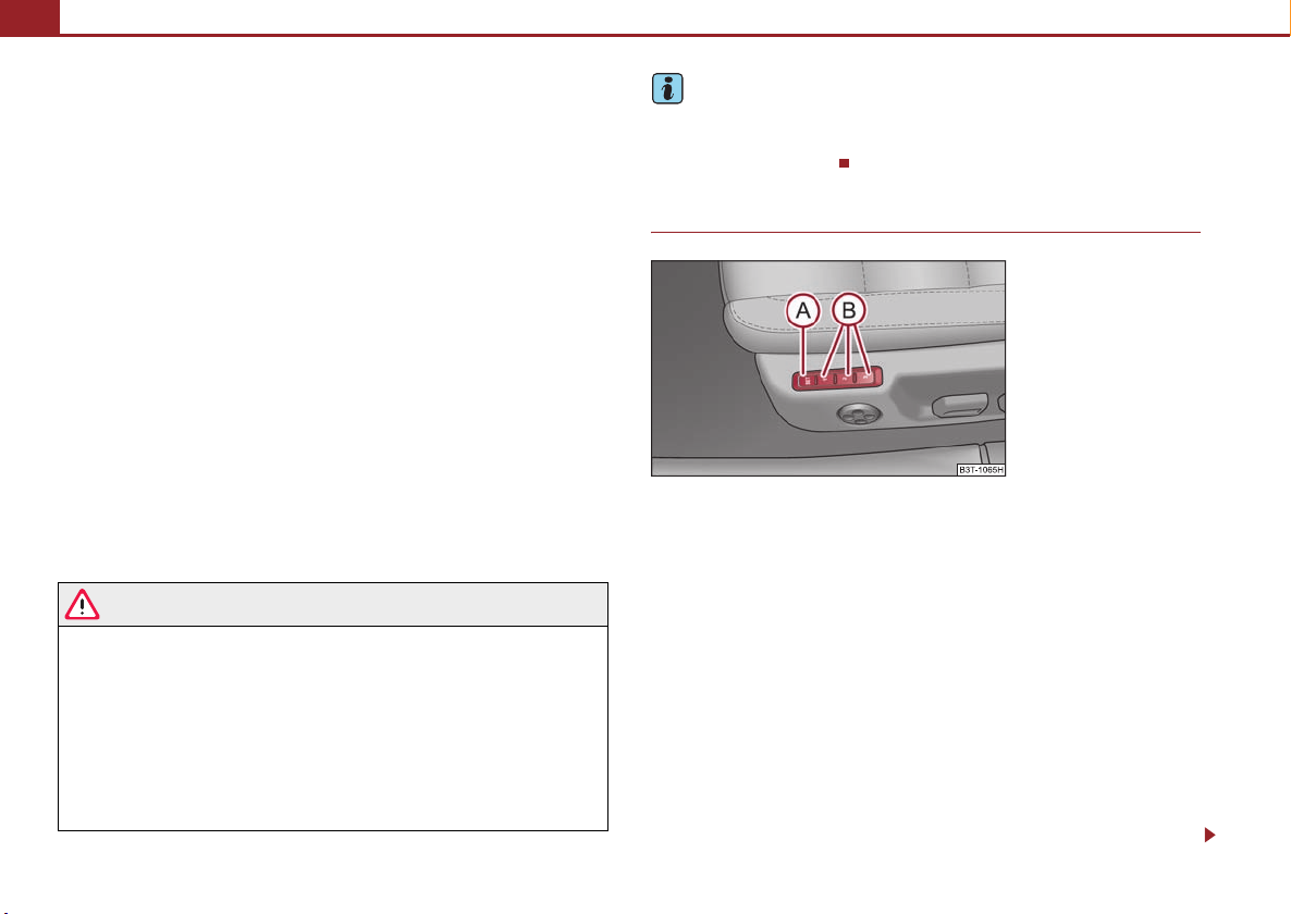
Seats and Stowage80
ABA2A3ACA
AAA
A
A
A
A
A
Adjust the angle of the seat
– Press the switch at the front ⇒ page 79, fig. 79 or at the back
⇒ page 79, fig. 79.
Adjusting the seat backrest
– Press the switch ⇒ page 79, fig. 78 in the direction of the desired
setting.
Adjusting lumbar support
– Press the switch front ⇒ page 79, fig. 78 in order to enlarge the
A
curvature of the lumbar support.
– Press the switch rear in order to reduce the curvature of the lumbar
support.
– Press the switch top in order to adjust the curvature of the lumbar
A
support higher.
– Press the switch bottom in order to adjust the curvature of the
A
lumbar support lower.
B
Switch is operated in order to move the seat up/down and forward/back, while
C
switch is operated in order to move the backrest forward or back.
WARNING
• Only adjust the driver seat when the vehicle is stationary - risk of injury!
• Caution when adjusting the seat! You may suffer injuries or bruises as a
result of adjusting the seat without paying proper attention.
• In view of the fact that the seats can also be adjusted when the ignition is
switched off (even when ignition key withdrawn), you should never leave
children unattended in the car.
• The seat backrests must not be angled too far back when driving other-
wise this will affect proper operation of the seat belts and of the airbag
system - risk of injury!
Note
If the movement of the seat is inadvertently interrupted during an adjustment, once
again press the switch in the appropriate direction and continue with the adjustment of the seat to the end.
Storing setting
Fig. 80 Driver seat: Memory
buttons and SET button
Storing seat and exterior mirror settings for driving forward
– Switch on the ignition.
– Adjust the seat ⇒ page 79.
– Adjust both exterior mirrors ⇒ page 76.
– Press button SET ⇒ fig. 80.
– Press one of the memory buttons within 10 seconds after pressing
A
B
the button SET - an acknowledgement signal confirms that the seat
setting is stored..
Storing exterior mirror setting for reversing*
– Switch on the ignition.
– Turn the exterior mirror control to position
⇒ page 76.
Page 82

Seats and Stowage 81
A
A
A
– Engage reverse gear.
– Move the right exterior mirror into the desired position ⇒ page 76.
– Take the vehicle out of gear. The set position of the exterior mirror is
stored.
Memory buttons
Memory for the seat offers the possibility to store the individual driver seat and
external mirror position. An individual position can be allocated to each of the three
memory buttons ⇒ page 80, fig. 80, that is three in total. After pressing the
corresponding memory button , the seat and the exterior mirror are automatically moved into the positions which have been allocated to this button ⇒ page 81.
Emergency Off
You can interrupt the setting operation at any time, if you operate any button of the
driver seat.
B
B
Note
• For safety reasons, it is not possible to store this position if the inclination angle
of the seat backrest is more than 102° in relation to the seat cushion.
• When storing settings with the memory buttons, we recommend that you begin
with the front button and assign a memory button to each additional driver.
• Each new setting stored with the same button erases the previous setting.
• Each time you store the seat and exterior mirror settings for driving forward you
also have to re-store the individual setting of the exterior mirror on the passenger
side for reversing.
Assigning remote control to the memory buttons
After storing the settings of the seat and exterior mirrors, you have 10
seconds in order to assign the radio remote control to the appropriate
memory button.
– Withdraw the ignition key.
– Press the unlock button ⇒ page 51, after the successful assignment
an audible signal will sound. The setting is stored with the memory
button which you have selected.
If you wish to be able to retrieve the settings which are stored in the memory by also
using the radio remote control, you have to assign the radio remote control to a
memory button in each case.
If you wish, you can obtain an additional remote control key from an authorised
Škoda Service partner and then assign the remote control key to another memory
button.
Note
• If the radio remote control had previously been assigned to another memory
button, this setting is then erased by the new assignment.
• If you assign the radio remote control to a memory button which has already
been assigned to a radio remote control, the old assignment is also replaced by a
new assignment in this case.
• The assignment of the radio remote control to a memory button is retained,
however, after reassigning the seats and exterior mirrors.
Retrieving settings of the seat and mirrors
You can retrieve the stored settings either with the memory buttons
or with the remote control*.
Retrieving settings with memory buttons
– In order to retrieve the stored setting, you have two possibilities:
– One-touch automatic memory: Briefly press the desired memory
B
button ⇒ page 80, fig. 80. The seat and exterior mirror are moved
automatically into the stored positions (this applies only if the ignition
is switched on and the speed is less than 5 km/h).
Using the system Safety Driving Tips General Maintenance Breakdown assistance Technical Data
Page 83

Seats and Stowage82
A
– Memory keying: Press and hold the desired memory button
B
pressed long enough until the seat and the exterior mirror are moved
into the stored positions.
Retrieving settings with remote control
– If the driver door is closed and the ignition is switched off, briefly press
the unlock button of the radio remote control ⇒ page 51 and then
open the driver door.
– The seat and exterior mirrors now move automatically into the stored
positions.
Retrieving setting of exterior mirror for reversing*
– Turn the rotary knob for the exterior mirror setting into the position
⇒ page 76 before engaging the reverse gear.
The mirror returns into its initial position, after the rotary knob is moved out of the
position and put into another position or if the speed is more than 15 km/h.
Emergency Off
You can interrupt the setting operation at any time, if you operate any button of the
driver seat.
Head restraints
Fig. 81 Adjusting head
restrai nt
Fig. 82 Removing a head
restrai nt
Best protection is achieved if the top edge of the head restraint is at the
same level as the upper part of your head.
Adjusting the height of a head restraint
– Grasp the side of the head restraint with both hands and push it in
upward direction as desired ⇒ fig. 81.
– Move the head restraint downwards if required by pressing and
holding the safety button with one hand ⇒ fig. 82 and by pressing
with the other hand the head restraint downwards.
Page 84

Seats and Stowage 83
AAA
Removing and installing a head restraint
– Pull the head restraint up out of the seat backrest as far as the stop (on
the rear head restraints fold forward the seat backrest).
– Press the locking button in the direction of arrow ⇒ page 82, fig. 82
and pull the head restraint out.
– To re-insert the head restraint, push it down into the seat backrest far
enough until you hear the locking button engage.
The position of the front and rear outer head restraints is adjustable in height. The
middle rear head restraint is adjustable in two positions.
The head restraints must be adjusted to match the size of the seat occupant.
Correctly adjusted head restraints together with the seat belts offer effective
protection for the occupants ⇒ page 164, “Correct seated position”.
WARNING
• The head res traints m ust be correct ly adjusted in order to offer effective
protection for the occupants in the event of an accident.
• Do not drive under any circumstance with removed head restraints - risk
of injury!
• If the rear seats are occupied, the rear head restraint must not be in the
lower position.
Middle rear head restraint
Fig. 83 Rear seats: middle
head restraint
IIn certain countries national legal provisions also require the equipment
of the rear seat with fixing eyes for child seat using the “Top Tether” system
⇒ page 192, “Attaching child seat using the “Top Tether” system”. For
vehicles, which are equipped with such fixing eyes, a deviating sequence
for removing the middle head restraint must be observed.
Removing and installing the rear middle head restraint
– Pull the head restraint out of the seat backrest as far as the stop.
– Press the locking button in the direction of arrow ⇒ fig. 83, press
simultaneously the locking button into the opening using a flat
screwdriver with a width of maximum 5 mm and pull out the head
restraint.
– To re-insert the head restraint, push it down into the seat backrest far
enough until you hear the locking button engage.
B
WARNING
• The head restraints must be correctly adjusted in order to offer effective
protection for the occupants in the event of an accident.
Using the system Safety Driving Tips General Maintenance Breakdown assistance Technical Data
Page 85
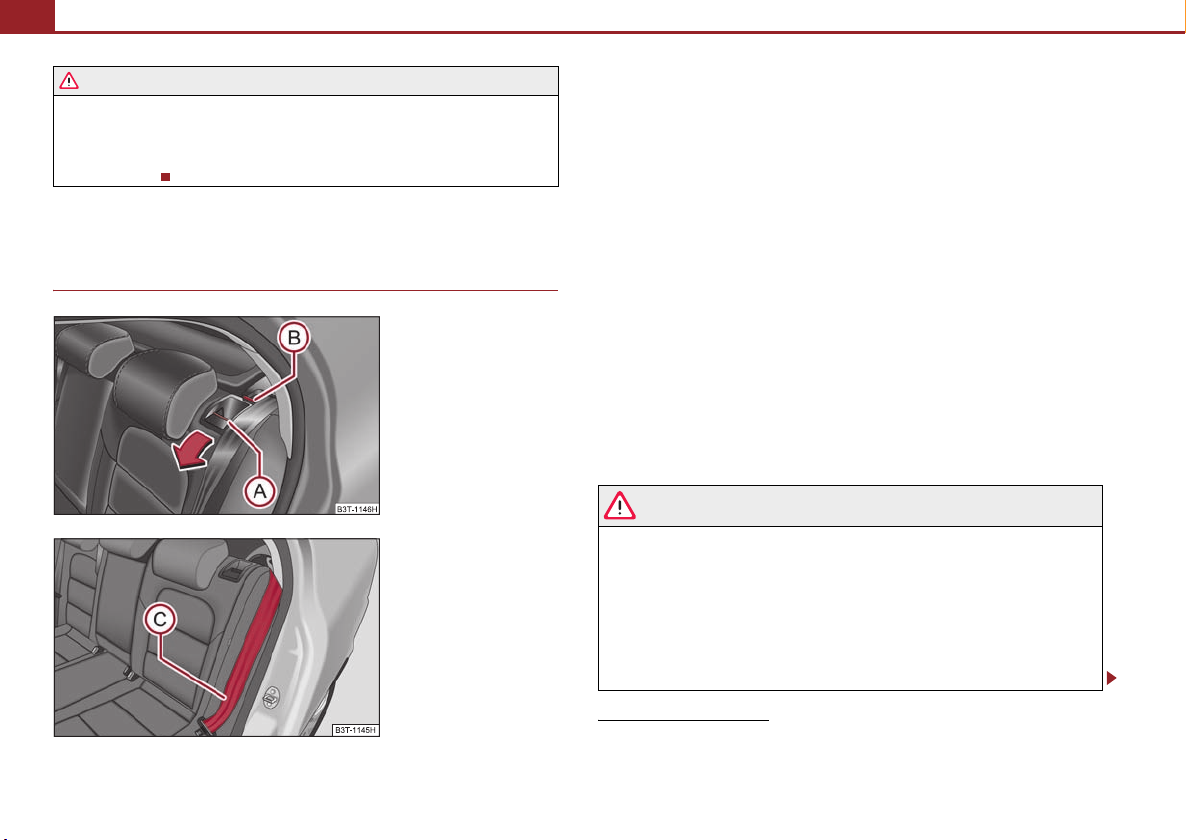
Seats and Stowage84
AAACA
WARNING (continued )
• Do not drive under any circumstance with removed head restraints - risk
of injury!
• If the rear seats are occupied, the rear head restraint must not be in the
lower position.
Rear seats
Folding the seat backrest forwards
Fig. 84 Unlock the seat backrest
Fig. 85 Lock the seat backrest
The luggage compartment can be increased in size by folding the seat
backrests forward.
Folding the seat backrests forward
– Before folding the seat backrests forwards, you must adapt the posi-
tion of the front seats in such a way that they are not damaged by the
folded seat backrests.
9)
– Unlock the seat backrest by pressing the unlocking handle
⇒ fig. 84 and fold it completely forwards.
Put the seat backrests into the original position
– Install the head restraint in the slightly lifted seat backrest.
– Place the rear lateral seat belt behind the edge of the side trim
panel ⇒ fig. 85.
– Then push the seat backrest back into the upright position until the
securing knob clicks into place - check by pulling on the seat backrest.
– Make sure that the red pin is covered ⇒ fig. 84.
B
WARNING
• The belts and the belt locks must be in their or iginal position after folding
back the seat backrests - they must be ready to use.
• The seat backrests must be securely interlocked in position so that no
objects in the luggage compartment can slide into the passenger compartment if there is sudden braking - risk of injury!
• Pay attention that the seat backrests are correctly interlocked. It is only
then that the three-point seat belt for the middle seat can reliably fulfil its
function.
9)
If the front seats are too far back, we recommend that you have the rear head restraints removed before the seat backrests are folded forward. Store the removed head restraints in
such a way that they cannot be damaged or soiled. Please refer to the guidelines ⇒ page 86 .
Page 86

Seats and Stowage 85
WARNING (continued )
• Before folding the seat backrest back into the secure position, place the
rear lateral seat belt behind the edge of the side trim panel. Take suitable
measures to prevent that the seat belt is jammed between the seat backrest
and the side trim panel and is thus damaged.
Rear seat armrest
Fig. 86 Rear seats: Armrest
– You can fold down the armrest to enhance occupant comfort
⇒ fig. 86.
Seat heaters*
Fig. 87 Dash panel: Regulator for front seat heating
Fig. 88 Centre console at
rear: Regulator for heating
the rear seats
You can electrically heat the seat backrests and the surfaces of the front
seats and the two outer rear seats.
– You can switch on and regulate the seat heating of the driver or front
passenger seat by pressing the surface of the regulator at the point at
which the symbol is located
⇒ fig. 87.
– You can switch on and adjust the heaters of the left or right rear seats
by pressing the regulator
⇒ fig. 88.
– With one press, you can switch the heating to highest intensity which
is indicated by the lighting up of the three warning lights in the switch.
Using the system Safety Driving Tips General Maintenance Breakdown assistance Technical Data
Page 87

Seats and Stowage86
– With repeated pressing of the switch, the intensity of the heating is
down-regulated up to the switch-off. The intensity of the heating is
indicated by the number of illuminated warning lights in the switch.
WARNING
If you have a subdued pain and/or temperature sensitivity, e.g. through
medication, paralysis or because of chronic illness (e.g. diabetes), we
recommend not to use the seat heating. This can lead to burns on the back,
the posterior and the legs which are difficult to heal. If the seat heating is
used, we recommend to make regular breaks in your journey when driving
long distances, so that in specific cases as mentioned above the body can
recuperate from the stress of the journey. Please consult your doctor, who
can evaluate your specific condition.
Caution
• You should not kneel on the seats or otherwise apply pressure at specific points
in order to avoid damaging the heating elements of the seat heaters.
• Do not use the seat heating if the seats are not occupied by persons or if objects
are fastened or stored on them, for example a child seat, a bag etc. A fault of the
heating elements in the seat heating can occur.
• Do not clean the seats moist ⇒ page 216.
Note
• The seat heating should only be switched on when the engine is running. This
has a significant effect of saving on the battery capacity.
• If the on-board voltage drops, the seat heating is switched off automatically, in
order to provide sufficient electrical energy for the engine control.
Pedals
Concerning a secure depressing of the pedal, you should use only footmats from
the Škoda genuine accessories.
Operation of the pedals must not be hindered!
WARNING
• Greater pedal distances may be needed when there is a fault in the brake
system.
• Do not place any footmats or o ther additional floor coverings in the area
of the pedals in order to ensure that all the pedals can be fully depressed and
are able to return unobstructed to their initial position - risk of accident!
• There must be no objects on the floor which could roll under the pedals.
You would then no longer be able to apply the brakes, operate the clutch or
accelerator - risk of accident!
luggage compartment
Loading the luggage compartment
Please observe the following in the interest of having good handling characteristics of your vehicle:
– Distribute the items of luggage as evenly as possible.
– Place heavy objects as far forward as possible.
– Attach the items of luggage to the lashing eyes or the safety net*
⇒ page 87.
In the event of an accident, there is such a high kinetic energy which is produced by
small and light objects that they can cause severe injuries. The magnitude of the
kinetic energy depends on the speed at which the vehicle is travelling and on the
weight of the object. The speed at which the vehicle is travelling is in this case the
more significant factor.
Example: In the event of a frontal collision at a speed of 50 km/h, an unsecured
object with a weight of 4.5 kg produces an energy, which corresponds to 20 times
its own weight. This means that it results in a weight of approx. 90 kg. You can
Page 88

Seats and Stowage 87
imagine the injuries that can occur, if this “bullet” is flying through the interior
compartment and hits an occupant.
WARNING
• Store the objects in the luggage compartment and attach them to the
lashing eyes.
• Loose objects in the passenger compartment can be thrown forward
during a sudden manoeuvre or in case of an accident and can injure the
occupants or other oncoming traffic. This risk is still increased, if the objects
which are flying around are hit by a deployed airbag. In this case, the objects
which are thrown back can injure the occupants - hazard.
• Please note that the handling properties of your vehicle may be affected
when transporting heavy objects as a result of the displacement of the
centre of gravity. The speed and style of driving must be adjusted accordingly.
• The items carried in the luggage compartment should be stored in such
a way that no objects are able to s lip forward if there are any sudden driving
or braking manoeuvres undertaken - risk of injury!
• Never drive with the boot lid fully opened or slightly ajar otherwise
exhaust gases may get into the interior of the vehicle - risk of poisoning!
• On no account exceed the permissible axle loads and the permissible
gross weight of the vehicle - risk of accident!
• Never transport occupants in the luggage compartment!
Caution
Please ensure that the heating elements of the rear window heater are not
damaged as a result of objects sliding in this area.
Lashing eyes
Fig. 89 Luggage compartment: Lashing eyes
Eyes are located on the sides of the loading area for lashing the good s to be loaded.
You can also attach a floor fixing net* to these eyes for lashing small objects.
WARNING
• The load to be transported must be fixed in place in such a way that it
cannot move during the journey and when braking.
• If the items of luggage or objects are attached to the lashing eyes with
unsuitable or damaged lashing straps, injuries can occur in the event of
braking manoeuvres or accidents. In order to prevent the items of luggage
being thrown forward, always use suitable lashing straps which are firmly
attached to the lashing eyes.
Note
Tyre pressure must be adjusted to the load ⇒ page 235, fig. 210.
Using the system Safety Driving Tips General Maintenance Breakdown assistance Technical Data
Page 89
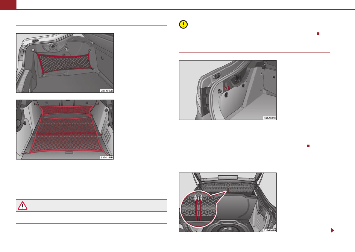
Seats and Stowage88
Fixing nets - Net programme*
Fig. 90 Fixing net: Vertical
pocket
Fig. 91 Fixing net: Floor
fixing net and horizontal
pocket
Fixing examples for fixing net as vertical pocket ⇒ page 88, fig. 90, floor fixing net
and horizontal pocket ⇒ fig. 91.
The fixing nets* are stored in the right side storage compartment of the luggage
compartment.
Caution
Do not place any objects with sharp edges in the nets - risk of net damage.
Folding hooks
Fig. 92 Luggage compartment: folding hooks
Folding hooks for attaching small items of luggage, such as bags etc., are provided
on both sides of the luggage compartment ⇒ fig. 92.
An item of luggage weighing up to 10 kg can be attached to the hook.
Fixing floor covering of the luggage compartment
WARNING
The permissible load of the side nets is 3.5 kg. Heavy objects are not secured
sufficiently - risk of injury and net damage!
Fig. 93 Luggage compartment: Fixing of the floor
covering
Page 90
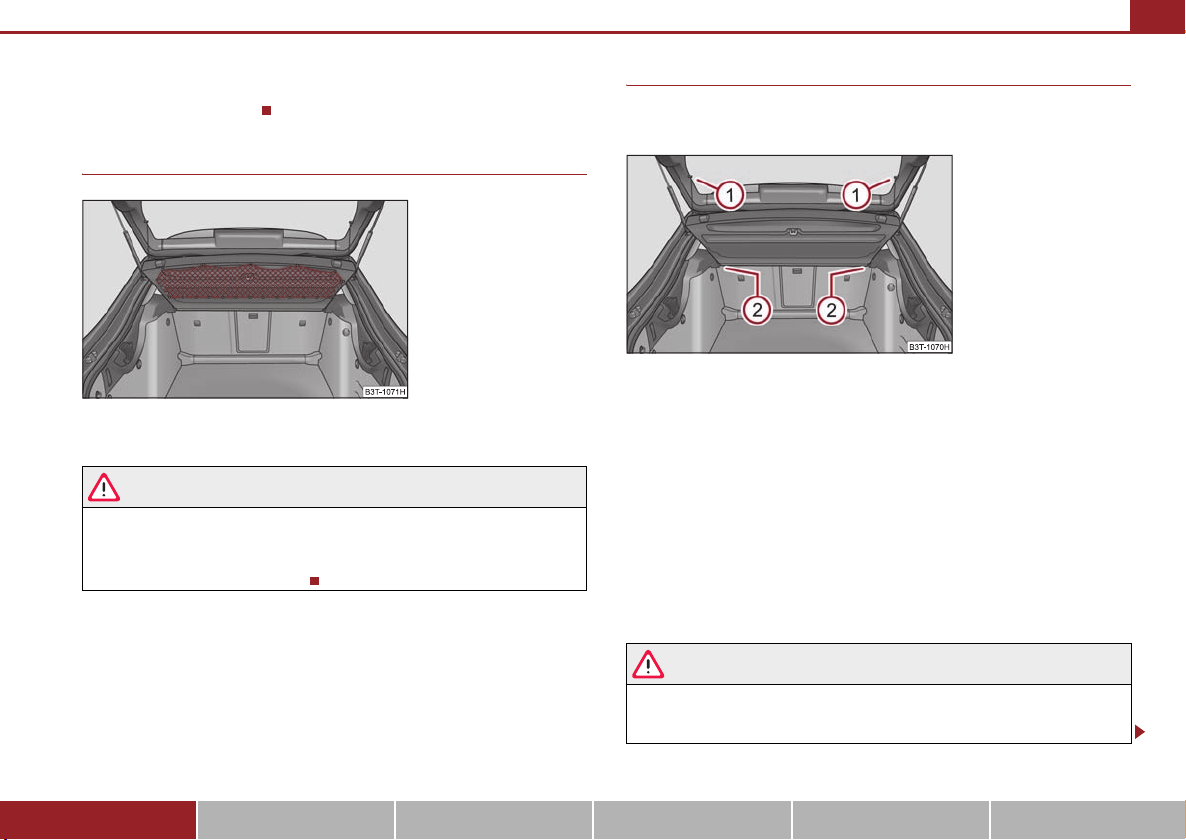
Seats and Stowage 89
A
A
A2A
A loop is located on the floor covering of the luggage compartment ⇒ fig. 93. W hen
handling the spare wheel, you can raise the floor covering and fix it on a hook at the
luggage compartment cover.
Luggage net*
Fig. 94 Luggage compartment: Luggage net
The luggage net is designed for the tranportation of lighter objects.
WARNING
• In the storage net you must only store objects (up to a total weight of 1.5
kg). Heavy objects are not secured sufficiently - risk of injury!
• No objects with sharp edges should be stored in the luggage net, because
they can damage the luggage net.
The luggage compartment cover
You can use the luggage compartment cover behind the head
restraints for storing light and soft items.
Fig. 95 Removing the
luggage compartment cover
The luggage compartment cover can be removed as required if one must
transport bulky goods.
– Unhook the support straps on the boot lid ⇒ fig. 95.
1
– Place the cover on the side supports.
– Pull the cover out of the holder horizontally to the rear.
2
– Install again by pushing the luggage compartment cover forwards into
the holder and hanging the support straps on the boot lid.
You can stow the removed luggage compartment cover behind the rear seat backrest.
1
WARNING
No objects should be placed on the luggage compartment cover, the vehicle
occupants could be endangered if there is sudden braking or the vehicle
collides with something.
Using the system Safety Driving Tips General Maintenance Breakdown assistance Technical Data
Page 91
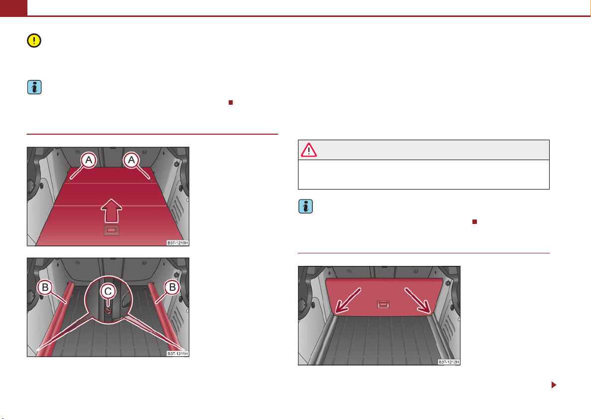
Seats and Stowage90
A
ABA
Caution
Please ensure that the heating elements of the rear window heater are not
damaged as a result of objects placed in this area.
Note
Opening the tailgate also lifts up the luggage compartment cover.
Remove variable* loading floor
Fig. 96 Luggage compartment: remove variable
loading floor
The variable loading floor makes handling of bulky items of luggage
easier. You can remove the variable loading floor if necessary.
– Unlock the loading floor by turning the safety eyes to the left by
A
approx. 90° ⇒ fig. 96.
– Fold together the loading floor and take it out by moving in direction
of arrow.
– Unlock the carrier rail by turning the arbor-mounted fixing eyes
C
to the right by approx. 90° ⇒ fig. 97.
WARNING
Pay attention when installing the variable loading floor that the carrier rail
and the variable loading floor are correctly fastened. If this is not the case,
there is risk of injury for the occupants.
Note
The maximum load of the variable loading floor is 75°kg.
Divide the luggage compartment with variable loading floor*
Fig. 97 Luggage compartment: Install carrier rails
Fig. 98 Luggage compartment: Separation of the
luggage compartment
The luggage compartment can be divided with the variable loading floor.
Page 92
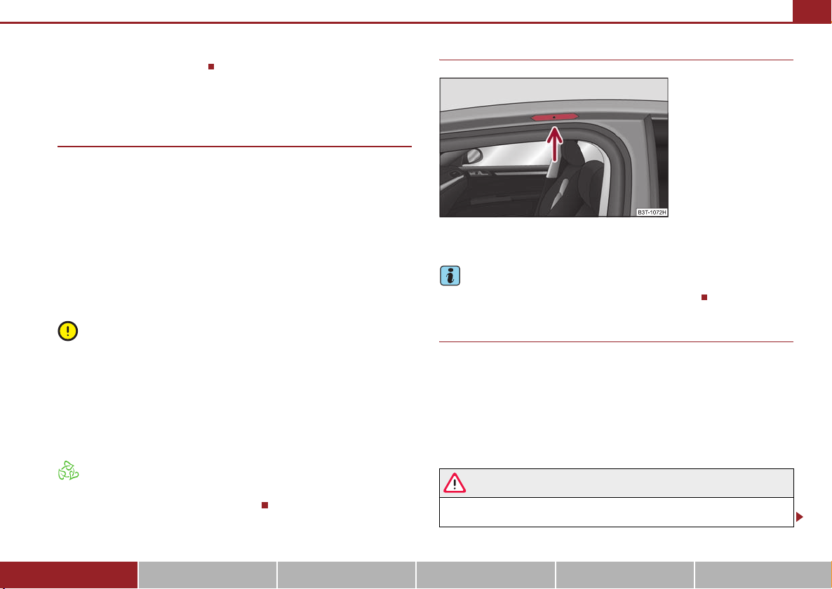
Seats and Stowage 91
– Lift up the part with the holder and secure it by sliding it into the
grooves ⇒ page 90, fig. 98.
The roof rack*
Description
Pay attention to the following points if you wish to transport luggage or other items
on the roof of your vehicle:
• A special roof luggage rack system was developed for the vehicle, that is why
you should only use a roof luggage rack which has been released for use by Škoda
Auto.
• The base carrier is the basis for a complete roof luggage rack system. Separate
additional holders are required for safety reasons for transporting luggage, bikes,
surfboards, skis and boats.
• The basic version of the roof luggage rack system and further components are
obtainable as accessories from the authorised Škoda Service Partners.
Caution
• If you use other roof rack systems or i f the roof bars are not properly fitted, then
any damage which may result to your car is not covered by the warranty agreements. It is therefore essential to pay attention to the fitting instructions supplied
with the roof luggage rack system.
• On models fitted with a power sliding/tilting roof, ensure that the opened
sliding/tilting roof does not strike any items of luggage transported on the roof.
• Ensure that the opened boot lid does not collide with the roof load.
Attachment points
Fig. 99 Attachment points
for base roof carrier
Perform the assembly and the disassembly according to the attached instructions.
Note
If you have any questions, please contact a specialist garage.
Roof load
Distribute weight evenly over the roof luggage rack system. The maximum permissible roof load (including roof rack system) of 100 kg and the maximum permissible
total weight of the vehicle should not be exceeded.
You cannot make full use of the permissible roof load if you use a roof luggage rack
system with a lower load carrying capacity. The load transported on the roof
luggage rack system must not exceed the weight limit which is stated in the fitting
instructions.
For the sake of the environment
The increased aerodynamic drag results in a higher fuel consumption. One should
therefore take off the roof bar system after use.
Using the system Safety Driving Tips General Maintenance Breakdown assistance Technical Data
WARNING
• The items which you transport on the roof bar system must be reliably
attached - risk of accident!
Page 93
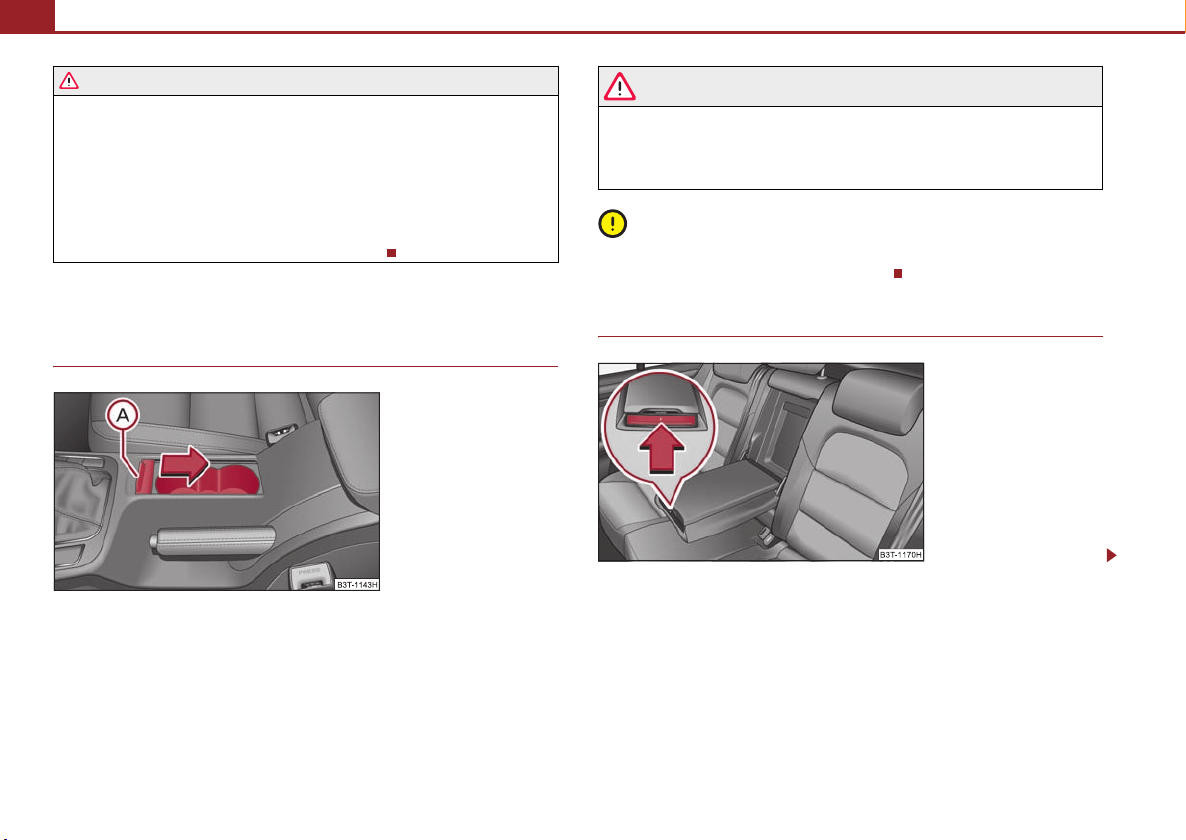
Seats and Stowage92
A
WARNING (continued )
• You must on no account exceed the permissible roof load, the permis-
sible axle loads and the permissible gross weight of your vehicle - risk of
accident!
• Please note that the handling properties of your vehicle change when
you transport heavy or bulky items on the roof bar system as a result of the
displacement of the centre of gravity and the increased wind attack area risk of accident! You must absolutely adapt your style of driving and the
speed of the vehicle to the specific circumstances.
Cup holder
Cup holder in front centre console
Fig. 100 Front centre
console: Cup holder
You can place two cups or beverage cans into the recesses ⇒ fig. 100.
On vehicles which are fitted with a cover for cup holders*, you can cover the cup
holder by pulling at the handle .
A
WARNING
• Do not place any hot beverages into the cup holder while the car is
moving. The hot beverages may spill - risk of scalding!
• Do not use any cups or beakers which are made of brittle material (e.g.
glass, porcelain). You might be injured by them in the event of an accident.
Caution
Do not open the beverages in the cup holder while driving. They may spill when
braking and while doing so damage the vehicle.
Cup holder in the armrest of the rear seats*
Fig. 101 Armrest of rear
seats: Cup holder
Page 94
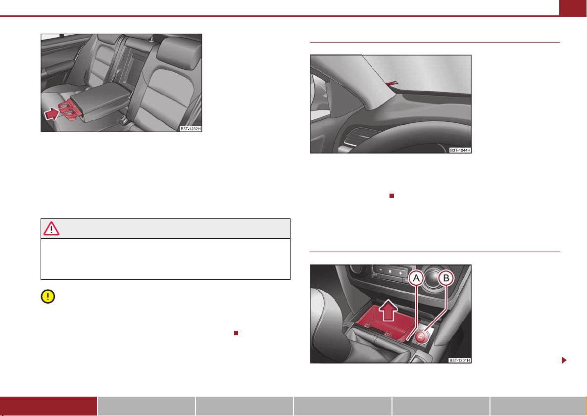
Fig. 102 Armrest of rear
seats: Insert cup holder
You can place two cups into the cup holder.
– If you press on the face end of the armrest in the direction of arrow
⇒ page 92, fig. 101, the cup holder comes out.
– In order to slide the cup holder in again, press the middle part of the
cup holder ⇒ page 93, fig. 102 and slide it into the armrest.
Seats and Stowage 93
Note holder
Fig. 103 Windscreen: Note
holder
The note holder is designed e.g. for attaching a car park ticket in parking areas.
The attached note has to always be remove d before starting off in order not to
restrict the driver's vision.
WARNING
• Do not place any hot beverages into the cup holder while the car is
moving. The hot beverages may spill - risk of scalding!
Ashtray
Front ashtray*
• Do not use any cups or beakers which are made of brittle material (e.g.
glass, porcelain). You might be injured by them in the event of an accident.
Caution
• Do not open the beverages in the cup holder while driving. They ma y spill when
braking and while doing so damage the vehicle.
• Before raising the armrest, first of all slide in the cup holder.
Fig. 104 Centre console:
Front ashtray
Using the system Safety Driving Tips General Maintenance Breakdown assistance Technical Data
Page 95
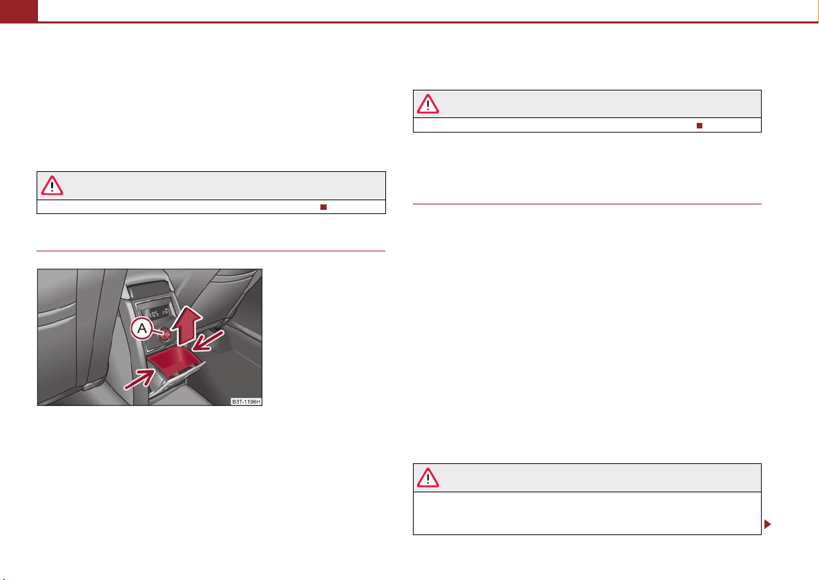
Seats and Stowage94
A
AAA
Removing ashtray insert
– Open the ashtray ⇒ page 97, fig. 110.
– Grasp the ashtray insert at the point ⇒ fig. 104 and take it out in
A
direction of arrow.
Insert ashtray insert
– Insert the ashtray vertically downwards.
WARNING
Never lay flammable objects in the ashtray basin - risk of fire!
Rear ashtray*
Fig. 105 Centre console:
Rear ashtray
Removing ashtray insert
– Open the ashtray ⇒ page 99, fig. 117.
– Grasp the insert at the points marked with the arrows ⇒ fig. 105 and
take it out.
Insert ashtray insert
– Insert the ashtray insert into the mount and press it in.
WARNING
Never lay flammable objects in the ashtray basin - risk of fire!
Cigarette lighter*, power sockets
Cigarette lighter
You can also use the socket on the cigarette lighter for other electrical appliances.
Using the cigarette lighter
– Press the button of the lighter ⇒ fig. 105 or ⇒ page 93, fig. 104.
B
– Wait until the button jumps forward.
– Remove the cigarette lighter immediately and use it.
– Insert the cigarette lighter again into the socket.
Using the socket
– Remove the cover.
– Connect the plug of the electrical appliance to the socket.
The 12 volt power socket can also be used to supply power to electrical accessories
with a power uptake up to 180 watts.
WARNING
• Take care when using the cigarette lighter! Not paying proper attention
or incorrect use the cigarette lighter in an uncontrolled manner may result in
burns.
Page 96

Seats and Stowage 95
WARNING (continued )
• The cigarette lighter and the power socket also operates when the igni-
tion is switched off or the ignition key withdrawn. You should therefore
never leave children unattended in the vehicle.
Caution
Always use matching plugs to avoid damaging the power socket.
Note
• Connecting electrical components when the engine is not running will
drain the battery of the vehicle - risk of battery draining!
• Further information ⇒ page 241.
Power socket in the luggage compartment
Fig. 106 Luggage compartment: Power socket
– Open the cover of the power socket ⇒ fig. 106.
– Connect the plug of the electrical appliance to the socket.
You can only use the power socket for the connection of approved electrical accessories with a power uptake up to 180 watts. The vehicle battery will be discharged
in the process if the engine is stationary.
The same remarks apply here as for ⇒ page 94.
Further information ⇒ page 241.
Storage compartments
Overview
You will find the following storage facilities in your vehicle:
Storage compartment on the front passenger side ⇒ page 96
Storage compartment on the driver's side ⇒ page 97
Storage compartment in front centre console ⇒ page 97
Storage net on the front centre console ⇒ page 97
Storage compartment for spectacles* ⇒ page 98
Storage compartment in the front doors ⇒ page 98
Storage compartment below front passenger seat* ⇒ page 98
Front seat armrest with storage compartment ⇒ page 99
Rear armrest with storage compartment* ⇒ page 99
Storage compartment in rear centre console* ⇒ page 99
Storage compartment for an umbrella* ⇒ page 100
Seat backrest with opening for skis ⇒ page 100
Through-loading bag* ⇒ page 101
Side compartments in the luggage compartment* ⇒ page 102
Clothes hooks* ⇒ page 103
Using the system Safety Driving Tips General Maintenance Breakdown assistance Technical Data
Page 97
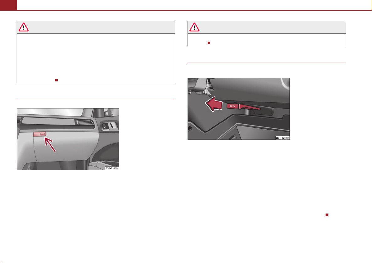
Seats and Stowage96
WARNING
• Please do not place anything on top of the dash panel. Such objects
might slide or fall down when driving (when accelerating or cornering) and
may distract you from concentrating on the traffic situation - risk of accident!
• Ensure that when driving no objects from the centre console of from
other storage possibilities may get into the footwell of the driver. You would
then no longer be able to apply the brakes, operate the clutch or accelerator
- risk of accident!
Storage compartment on the front passenger side
Fig . 107 D ash p anel : Stor age
compartment on the front
passenger side
Opening and closing the storage compartment on the front
passenger side
– Press the button ⇒ fig. 107 - the lid folds down.
– Raise the lid and press it until the catch is heard to engage.
In the storage compartment are pin holders.
WARNING
The storage compartment must always be closed when driving for safety
reasons .
Cooling of storage compartment on front passenger side
The compartment is fitted with an isolatable entry for cooled air.
Fig. 108 Storage compartment: Using cooling system
– Open the air supply by pulling on the lever in direction of arrow
⇒ fig. 108.
– The air supply closes by pressing the lever.
Opening the air supply when the air conditioning system is switched on allows
cooled air to flow into the storage compartment.
Opening the air inlet when the air conditioning system is on causes fresh or interior
air to flow into the storage compartment.
We recommend that you close the air supply if it is operating in the heating mode
or if you are not using the cooling system for the storage compartment.
Page 98
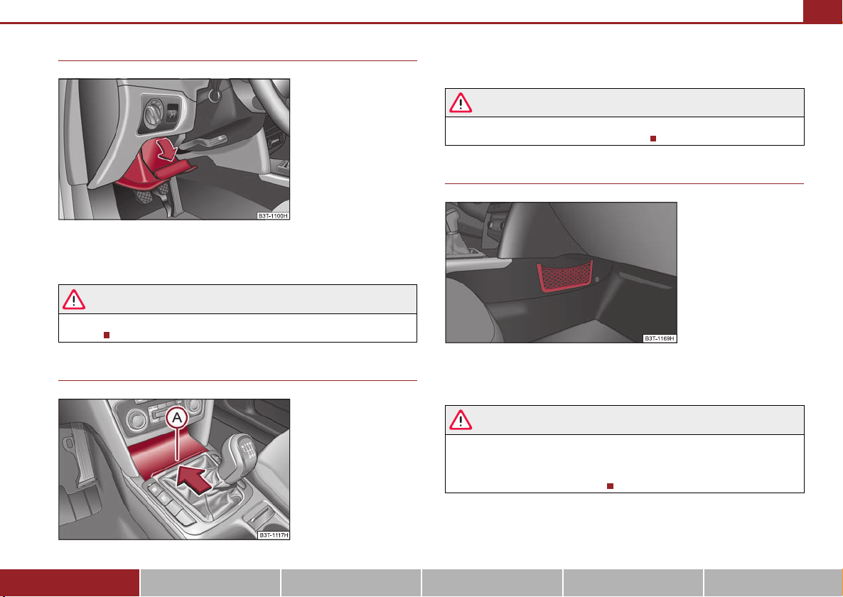
Seats and Stowage 97
A
Storage compartment on the driver's side
Fig . 109 D ash p anel : Stor age
compartment on the driver's
side
– The storage compartment is opened by lifting the handle and folding
open in the direction of arrow ⇒ fig. 109.
WARNING
The storage compartment must always be closed when driving for safety
reaso ns.
Storage compartment in front centre console
– Press on the lid at the point in direction of arrow ⇒ fig. 110, the lid
A
slides in.
WARNING
The storage compartment is not a substitute for the ashtray and must also
not be used for such purposes - risk of fire!
Storage net on the front centre console*
Fig. 111 Front centre
console: Storage net
The storage net in the front center console ⇒ fig. 111 is designed for the transport
of smaller objects.
WARNING
• In the storage net you must only store objects (up to a total weight of 0,5
kg). Heavy objects are not secured sufficiently - risk of injury!
• No objects with sharp edges should be stored in the luggage net, because
they can damage the luggage net.
Fig. 110 Front centre
console: Storage compartment
Using the system Safety Driving Tips General Maintenance Breakdown assistance Technical Data
Page 99

Seats and Stowage98
A
Storage compartment for spectacles*
Fig. 112 Detail of the headliner: Storage compartment
for spectacles
– Press button , the storage compartment folds down ⇒ fig. 112.
A
WARNING
The compartment must only be opened when removing or inserting objects
and otherwise must be kept closed.
Caution
On vehicles which are fitted with an anti-theft alarm system*, the opened storage
compartment reduces the effectiveness of the sensors for the interior monitor*.
Storage compartment in the front doors
Fig. 113 Storage compartment in the front doors
WARNING
Use the storage compartments in the door panels ⇒ fig. 113 only for small
items which do not project out of the compartment in order to avoid any
interference with the proper operation of the side airbags.
Storage compartment below front passenger seat*
Fig. 114 Front passenger
seat: Storage compartment
Page 100
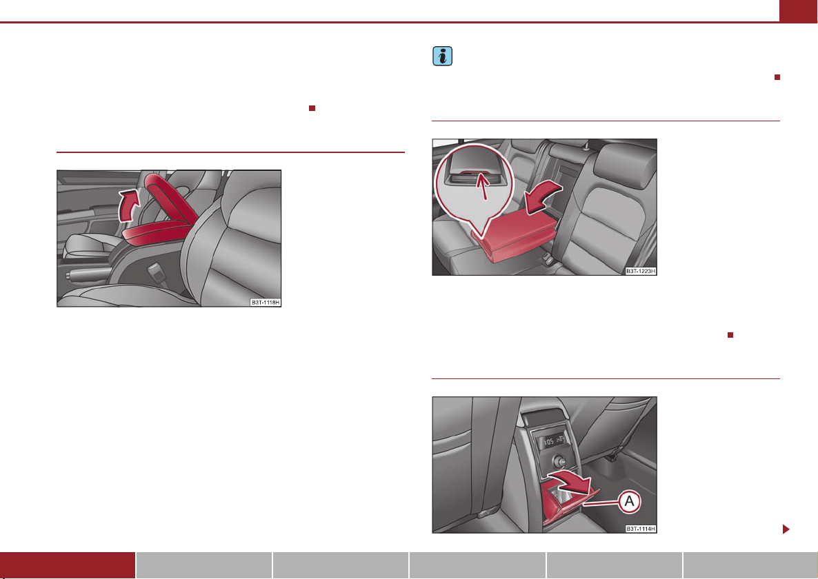
Seats and Stowage 99
The storage compartment is foreseen for storing small objects of up to 1.5
kg. in weight.
– Tilt the lock to open the flap and pull out the flap ⇒ page 98, fig. 114.
– Tilt the lock to close the flap and press flap close.
Front seat armrest with storage compartment
Fig. 115 Armrest: Storage
compartment
The armrest is adjustable for height and length.
Opening storage compartment
– Open the lid of the armrest in the direction of arrow ⇒ fig. 115.
Closing storage compartment
– Open the lid up to the stop, then you can fold it downwards.
Note
Push the lid of the armrest up to stop to the rear before operating the handbrake.
Rear seat armrest with storage compartment*
Fig. 116 Armrest of rear
seats:
You can fold down the armrest to enhance occupant comfort.
The armrest includes a storage compartment. You open the compartment by
pressing the button on the front side and raising the cover ⇒ fig. 116.
Storage compartment in rear centre console
Setting height
– First of all fold the lid to the bottom and lift it in the direction of arrow
into one of the 4 fixed positions.
Adjusting in forward/back direction
– Push the lid into the desired position.
Using the system Safety Driving Tips General Maintenance Breakdown assistance Technical Data
Fig. 117 Centre console at
rear: Storage compartment
 Loading...