

ŠkodaSuperb
OWNER´ S MANUAL
SI MPLY CL EVER

Introduction
You have opted for a Škoda - our sincere thanks for your confidence in us.
Your new Škoda offers you a vehicle featuring the most modern engineering and a wide range of equipment
which you will undoubtedly wish to use to the full during your daily motoring. We therefore recommend that
you read this Owner's Manual attentively to enable you to become familiar with your vehicle and all that it
offers as quickly as possible.
Please do not hesitate to contact your Škoda dealer or importer should you have any further questions
regarding your vehicle or any problems which may arise. He will be ready at any time to receive your questions, suggestions and criticisms.
Any national legal provisions which vary from the information contained in this Owner's Manual take precedence over the information contained herein.
We wish you much pleasure with your Škoda and pleasant motoring at all times.
Your Škoda Auto

Introduction2
On-board literature
The on-board literature for your vehicle consists of this “Owner's
Manual” as well as the brochures “Service Schedule”, “Brief
Instruction”, “Technical Data” and “Help on the road ”. There
can also be a variety of other additional operating manuals and
instructions on-board (e.g. an operating manual for the radio)
depending on the vehicle model and equipment.
If one of the publications listed above is missing, please contact
a Škoda dealer immediately, where one will be glad to assist you
in such matters.
One should note that the details given in the vehicle's
papers always take precedence over those in the Owner's
Manual.
Owner's Manual
This Owner's Manual describes the current scope of equip-
ment. Certain items of equipment listed are only installed later on
and only envisaged for particular markets. The illustrations can
differ in minor details from your vehicle; they are only intended for
general information.
In addition to information regarding all the controls and equipment, the Owner's Manual also contains important information
regarding care and operation for your safety and also to retain the
value of your vehicle To provide you with valuable tips and aids.
You can learn how how you can operate your vehicle safely,
economically and in an environmentally conscious way.
For safety reasons, please also pay attention to the information on accessories, modifications and replacement of parts
⇒ page 233.
The other chapters of the Owner's Manual are also important,
however, for proper treatment of your car - in addition to regular
care and maintenance - helps to retain its value and in many
cases is also one of the requirements for warranty claims.
The Brief Instruction
includes an overview of the most important controls of your
vehicle.
The Service Schedule
contains:
• Vehicle data
• Service intervals
• Overview of the service work
• Service proof
• Confirmation of mobility warranty
• important information on the warranty
The confirmation of the service work carried out is a requirement
for a warranty claim.
Please always present the Service Schedule when you take your
car to a Škoda dealer.
If the Service Schedule is missing or worn, please contact your
Škoda dealer, where your car is serviced regularly. You will
receive a duplicate, in which the previously carried out service
work are confirmed.
Help on the road
contains the addresses and telephone numbers of Škoda
Importers.

Technical Data
includes the most important identification data of your vehicle.
Introduction 3

Introduction4

Contents
Contents 5
Layout of this Owner's Manual
(symbol explanation)
. . . . . . . . . . .
Using the system . . . . . . . . . . . . . . .
Cockpit . . . . . . . . . . . . . . . . . . . . . . . . . . . . . . .
An overview . . . . . . . . . . . . . . . . . . . . . . . . . .
Instruments and Indicator/Warning Lights
Instrument cluster . . . . . . . . . . . . . . . . . . . . . .
Engine revolutions counter . . . . . . . . . . . . . . .
Coolant temperature gauge . . . . . . . . . . . . . .
Fuel gauge . . . . . . . . . . . . . . . . . . . . . . . . . . .
Digital clock . . . . . . . . . . . . . . . . . . . . . . . . . .
Speedometer with counter for distance driven
Service Interval Display . . . . . . . . . . . . . . . . .
Multi-functional indicator (onboard computer)
Information display* . . . . . . . . . . . . . . . . . . . .
Auto Check Control . . . . . . . . . . . . . . . . . . . .
Warning lights . . . . . . . . . . . . . . . . . . . . . . . . .
Unlocking and locking . . . . . . . . . . . . . . . . . .
Keys . . . . . . . . . . . . . . . . . . . . . . . . . . . . . . . .
Child safety locks . . . . . . . . . . . . . . . . . . . . . .
Central locking system . . . . . . . . . . . . . . . . . .
Remote control . . . . . . . . . . . . . . . . . . . . . . . .
Anti-theft alarm system* . . . . . . . . . . . . . . . . .
Power windows . . . . . . . . . . . . . . . . . . . . . . .
Electric sliding/tilting roof* . . . . . . . . . . . . . . .
Lights and Visibility . . . . . . . . . . . . . . . . . . . . .
Lights . . . . . . . . . . . . . . . . . . . . . . . . . . . . . . .
Interior lighting . . . . . . . . . . . . . . . . . . . . . . . .
Visibility . . . . . . . . . . . . . . . . . . . . . . . . . . . . .
The windscreen wiper and washing system .
Rear-view mirror . . . . . . . . . . . . . . . . . . . . . .
8
Seats and Stowage . . . . . . . . . . . . . . . . . . . .
Front seats . . . . . . . . . . . . . . . . . . . . . . . . . . .
Adjusting front seats manually . . . . . . . . . . . .
9
Adjusting front seats electrically* . . . . . . . . . .
11
Front passenger seat with a folding central back
11
rest* . . . . . . . . . . . . . . . . . . . . . . . . . . . . . . . .
Footrest at the rear* . . . . . . . . . . . . . . . . . . . .
13
Seat heaters* . . . . . . . . . . . . . . . . . . . . . . . . .
13
Pedals . . . . . . . . . . . . . . . . . . . . . . . . . . . . . .
14
Luggage compartment . . . . . . . . . . . . . . . . . .
14
The cool box in the armrest of rear seats* . . .
14
CargoFlex folding box* . . . . . . . . . . . . . . . . . .
15
The roof luggage rack system . . . . . . . . . . . .
16
Drinks can holder . . . . . . . . . . . . . . . . . . . . . .
16
Ashtray . . . . . . . . . . . . . . . . . . . . . . . . . . . . . .
18
Cigarette lighters and power sockets . . . . . . .
22
Storage facilities . . . . . . . . . . . . . . . . . . . . . . .
24
28
Heating and air conditioning system . . . . .
The air conditioning system . . . . . . . . . . . . . .
38
Climatronic* (automatic air conditioning) . . . .
38
41
Starting-off and Driving . . . . . . . . . . . . . . . . .
41
Setting steering wheel position . . . . . . . . . . .
46
Ignition lock . . . . . . . . . . . . . . . . . . . . . . . . . .
48
Starting engine . . . . . . . . . . . . . . . . . . . . . . . .
50
Switching the engine off . . . . . . . . . . . . . . . . .
53
Shifting (manual gearbox) . . . . . . . . . . . . . . .
Handbrake . . . . . . . . . . . . . . . . . . . . . . . . . . .
56
Parking aid* . . . . . . . . . . . . . . . . . . . . . . . . . .
56
Cruise control system (CCS)* . . . . . . . . . . . .
60
62
Automatic gearbox* . . . . . . . . . . . . . . . . . . . .
5-speed automatic gearbox . . . . . . . . . . . . . .
64
Communicating and Navigating . . . . . . . . .
66
Multifunction steering wheel* . . . . . . . . . . . . .
Mobile phone, two-way radio system and
69
navigation system . . . . . . . . . . . . . . . . . . . . .
69
70
71
Safety . . . . . . . . . . . . . . . . . . . . . . . . . . . . . .
76
Passive Safety . . . . . . . . . . . . . . . . . . . . . . . .
77
Basic information . . . . . . . . . . . . . . . . . . . . . .
78
Correct seated position . . . . . . . . . . . . . . . . .
79
Seat belts . . . . . . . . . . . . . . . . . . . . . . . . . . . . .
79
Why seat belts? . . . . . . . . . . . . . . . . . . . . . . .
84
The physical principle of a frontal collision . .
87
Important safety information regarding the use
90
of seat belts . . . . . . . . . . . . . . . . . . . . . . . . . .
92
How are seat belts correctly fastened? . . . . .
93
Belt tensioners . . . . . . . . . . . . . . . . . . . . . . . .
95
Airbag system . . . . . . . . . . . . . . . . . . . . . . . . .
97
Description of the airbag system . . . . . . . . . .
104
Front airbags . . . . . . . . . . . . . . . . . . . . . . . . .
104
Side airbags . . . . . . . . . . . . . . . . . . . . . . . . . .
109
Head airbags* . . . . . . . . . . . . . . . . . . . . . . . .
116
Deactivating an airbag . . . . . . . . . . . . . . . . . .
116
Transporting children safely . . . . . . . . . . . .
117
What you should know about transporting
118
children! . . . . . . . . . . . . . . . . . . . . . . . . . . . . .
119
Child seat . . . . . . . . . . . . . . . . . . . . . . . . . . . .
120
Attaching child safety seat . . . . . . . . . . . . . . .
121
122
123
126
126
132
132
136
139
139
139
141
145
145
146
147
148
150
152
152
154
157
159
161
164
164
168
171

Contents6
Driving Tips . . . . . . . . . . . . . . . . . . . . . .
Intelligent Technology . . . . . . . . . . . . . . . . . .
Electronic stability programme (ESP)* . . . . . .
Brakes . . . . . . . . . . . . . . . . . . . . . . . . . . . . . .
Brake booster . . . . . . . . . . . . . . . . . . . . . . . .
Antilock brake system (ABS) . . . . . . . . . . . . .
Brake Assist* . . . . . . . . . . . . . . . . . . . . . . . . .
Power steering . . . . . . . . . . . . . . . . . . . . . . . .
Driving and the Environment . . . . . . . . . . . .
The first 1 500 kilometres and then afterwards
Catalytic converter . . . . . . . . . . . . . . . . . . . . .
Motoring abroad . . . . . . . . . . . . . . . . . . . . . . .
Avoiding damage to your vehicle . . . . . . . . . .
Driving in an economical and environmentally
conscious manner . . . . . . . . . . . . . . . . . . . . .
Environmental compatibility . . . . . . . . . . . . . .
Towing a trailer . . . . . . . . . . . . . . . . . . . . . . . .
Towing a trailer . . . . . . . . . . . . . . . . . . . . . . . .
Detachable towing device* . . . . . . . . . . . . . .
General Maintenance . . . . . . . . . .
Care and cleaning . . . . . . . . . . . . . . . . . . . . .
General . . . . . . . . . . . . . . . . . . . . . . . . . . . . .
Care of the exterior of vehicle . . . . . . . . . . . .
Care of the interior of vehicle . . . . . . . . . . . . .
Fuel . . . . . . . . . . . . . . . . . . . . . . . . . . . . . . . . . .
Petrol . . . . . . . . . . . . . . . . . . . . . . . . . . . . . . .
Diesel . . . . . . . . . . . . . . . . . . . . . . . . . . . . . . .
Refuelling . . . . . . . . . . . . . . . . . . . . . . . . . . . .
Inspecting and Replenishing . . . . . . . . . . . .
Engine compartment . . . . . . . . . . . . . . . . . . .
Overview of the engine compartment . . . . . .
Engine oil . . . . . . . . . . . . . . . . . . . . . . . . . . . .
Cooling system . . . . . . . . . . . . . . . . . . . . . . .
Brake fluid . . . . . . . . . . . . . . . . . . . . . . . . . . .
175
The battery . . . . . . . . . . . . . . . . . . . . . . . . . .
Windscreen Wiper and Washer System . . . .
175
175
Wheels and Tyres . . . . . . . . . . . . . . . . . . . . .
178
Wheels . . . . . . . . . . . . . . . . . . . . . . . . . . . . .
179
Accessories, changes and replacement of
179
parts . . . . . . . . . . . . . . . . . . . . . . . . . . . . . . . . .
180
Accessories and replacement parts . . . . . . .
181
Technical changes . . . . . . . . . . . . . . . . . . . . .
182
182
Breakdown assistance . . . . . . . .
183
184
Breakdown assistance . . . . . . . . . . . . . . . . .
184
First-aid box* . . . . . . . . . . . . . . . . . . . . . . . . .
Warning triangle . . . . . . . . . . . . . . . . . . . . . .
185
Fire extinguisher* . . . . . . . . . . . . . . . . . . . . . .
189
Vehicle tool kit . . . . . . . . . . . . . . . . . . . . . . . .
190
Spare wheel . . . . . . . . . . . . . . . . . . . . . . . . . .
190
Changing a wheel . . . . . . . . . . . . . . . . . . . . .
192
Jump-starting . . . . . . . . . . . . . . . . . . . . . . . . .
Tow-starting and towing vehicle . . . . . . . . . . .
195
Fuses and light bulbs . . . . . . . . . . . . . . . . . .
Electric fuses . . . . . . . . . . . . . . . . . . . . . . . . .
195
Bulbs . . . . . . . . . . . . . . . . . . . . . . . . . . . . . . .
195
195
201
Technical Data . . . . . . . . . . . . . . . . . . .
204
General . . . . . . . . . . . . . . . . . . . . . . . . . . . . . .
204
Identification data . . . . . . . . . . . . . . . . . . . . .
204
206
Index . . . . . . . . . . . . . . . . . . . . . . . . . . . . . . .
208
208
210
211
214
217
218
223
225
225
233
233
233
235
235
235
235
236
236
237
238
245
247
250
250
252
259
259
259
261

Contents 7
Layout of this Owner's Manual (symbol explanation)8
Layout of this Owner's Manual (symbol explanation)
The Owner's Manual has been systematically designed, in order to make
it easy for you to find and absorb the information you require.
Chapters, table of contents and subject index
The text of the manual are divided into relatively short sections which are
combined into easy-to-read chapters. The chapter you are reading at any
particular moment is highlighted at the bottom right of the page.
The Table of contents is arranged according to the chapters and the
detailed Subject index at the end of the Owner's Manual helps you to
rapidly find the information you are looking for.
Sections
The majority of Sections apply to all models.
Since there is a wide range of different equipment and options available it
is clearly unavoidable, despite dividing the contents into sections, that
mention may be made of equipment which is not fitted to your vehicle.
Equipment which is marked * is only standard on certain vehicle model
versions or only suppliable as optional equipment for certain models.
Brief information and instructions
Each section has a Heading.
This is followed by Brief information (in large italic lettering), which tells
you the subject which is dealt with in this section.
Most of the illustrations are accompanied by an Instruction (in relatively
large letters) which explains to you in a straightforward way the action you
have to take. Work steps which have to be carried out are illustrated with
a hyphen.
Notes
There are 4 different notes. Such guidelines are presented together at the
end of the section.
WARNING
The most important notes are marked with the heading Warning.
These Warning notes draw your attention to a serious risk of accident or injury. While reading the text you will frequently encounter
a double arrow followed by a small warning symbol. This symbol is
intended to draw your attention to a Warning note at the end of the
section to which you must pay careful attention.
Caution
OnA Caution note draws your attention to the possibility of damage to
your vehicle (e.g. damage to gearbox), or points out general risks of an
accident .
For the sake of the environment
An Environmental note draws your attention to environmental protection
aspects. This is where you will, for example, find tips aimed at reducing
your fuel consumption.
Note
A normal Note draws your attention in a general way to important information.
Direction indications
All direction indications such as “left”, “right”, “front”, “rear” relate to the
direction of travel of the vehicle.

Using the system
9
Using the system Safety Driving Tips General Maintenance Breakdown assistance Technical Data
Cockpit10
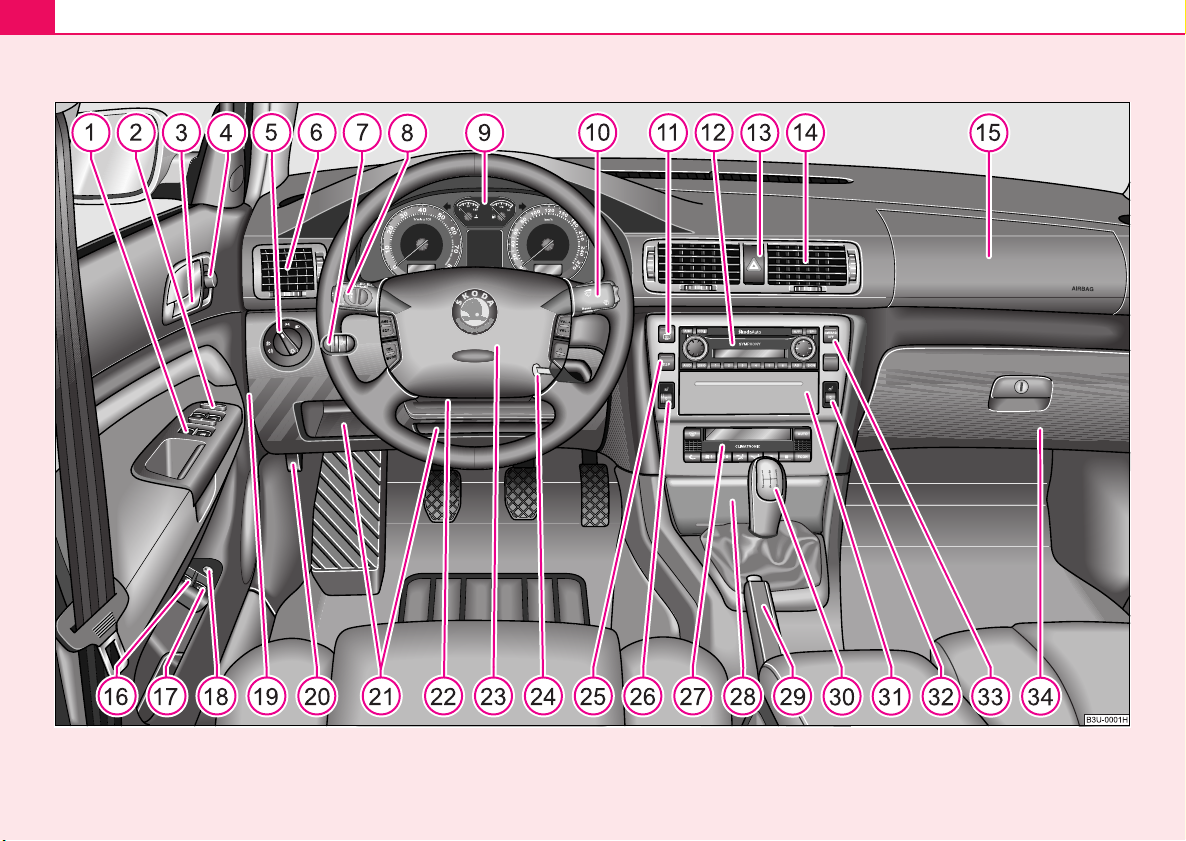
Fig. 1 Certain items of equipment shown in the illustration are only fitted to particular model versions or are optional items of equipment.
Cockpit
A
A
A
A
A
A
A
A
A
A
A
A12A
A
A
A
A
A
A
A
A
A
A
A
A
A
A
A
A
A
A
A
A
A
Cockpit 11
An overview
This general view is designed to help you to quickly
become familiar with the instruments, gauges and
controls.
1
Power windows . . . . . . . . . . . . . . . . . . . . . . . . . . . . . . . . . .
2
Central locking switch . . . . . . . . . . . . . . . . . . . . . . . . . . . . .
3
Door handle
4
Electric exterior mirror adjustment . . . . . . . . . . . . . . . . . . . .
5
Light switch . . . . . . . . . . . . . . . . . . . . . . . . . . . . . . . . . . . . .
6
Air outlet vents . . . . . . . . . . . . . . . . . . . . . . . . . . . . . . . . . . .
7
Headlight range adjustment . . . . . . . . . . . . . . . . . . . . . . . . .
8
Lever for turn signal lights and main beam . . . . . . . . . . . . .
9
Instrument cluster . . . . . . . . . . . . . . . . . . . . . . . . . . . . . . . .
10
Lever and switches for:
− Windshield wiper/wash system . . . . . . . . . . . . . . . . . . . .
− Multi-functional indicator . . . . . . . . . . . . . . . . . . . . . . . . .
11
Switch for rear window heater . . . . . . . . . . . . . . . . . . . . . . .
Depending on equipment fitted:
− Radio
− Navigation system (Navigation, Radio, CD Player)
13
Switch for hazard warning lights . . . . . . . . . . . . . . . . . . . . .
14
Air outlet vents . . . . . . . . . . . . . . . . . . . . . . . . . . . . . . . . . . .
15
Front passenger airbag . . . . . . . . . . . . . . . . . . . . . . . . . . . .
16
Fuel filler flap remote release . . . . . . . . . . . . . . . . . . . . . . .
17
Boot lid remote release . . . . . . . . . . . . . . . . . . . . . . . . . . . .
18
Deactivating boot lid remote release . . . . . . . . . . . . . . . . . .
50
44
67
56
108
58
59
13
64
18
62
58
108
154
44
44
44
19
Fuse box (on side of dash panel) . . . . . . . . . . . . . . . . . . . .
20
Bonnet remote release . . . . . . . . . . . . . . . . . . . . . . . . . . . .
21
Storage compartments . . . . . . . . . . . . . . . . . . . . . . . . . . . .
22
Lever for adjusting the steering wheel . . . . . . . . . . . . . . . .
23
Steering wheel:
− with horn
− with driver airbag . . . . . . . . . . . . . . . . . . . . . . . . . . . . . .
− with pushbuttons for radio, mobile phone and cruise
control system (CCS) . . . . . . . . . . . . . . . . . . . . . . . . . . .
24
Ignition lock . . . . . . . . . . . . . . . . . . . . . . . . . . . . . . . . . . . . .
25
Depending on equipment fitted:
− Switch for ESP* . . . . . . . . . . . . . . . . . . . . . . . . . . . . . . .
− Switch for TCS* . . . . . . . . . . . . . . . . . . . . . . . . . . . . . . .
26
Control dial for heating on the driver's seat . . . . . . . . . . . .
27
Depending on equipment fitted:
− Air conditioning . . . . . . . . . . . . . . . . . . . . . . . . . . . . . . . .
− Climatronic . . . . . . . . . . . . . . . . . . . . . . . . . . . . . . . . . . .
28
Ashtray, cigarette lighter/socket . . . . . . . . . . . . . . . . . . . . .
29
Handbrake . . . . . . . . . . . . . . . . . . . . . . . . . . . . . . . . . . . . .
30
Depending on equipment fitted:
− Gearshift lever for manual gearbox . . . . . . . . . . . . . . . .
− Selector lever for automatic gearbox . . . . . . . . . . . . . . .
31
Storage compartment . . . . . . . . . . . . . . . . . . . . . . . . . . . . .
32
Control dial for heating on the front passenger seat . . . . . .
33
Indicator light for a switched off front seat passenger airbag*
34
Lockable storage compartment on the front passenger side
250
208
97
116
154
132
117
175
176
78
104
109
93
121
120
126
97
78
162
97
Using the system Safety Driving Tips General Maintenance Breakdown assistance Technical Data

Cockpit12
Note
• Equipment which is marked * is only standard on certain vehicle model
versions or only suppliable as optional equipment for certain models.
• Vehicles with factory-fitted radio, mobile phone, navigation system, CD
player etc. are supplied with separate instructions for operating such
equipment.
• The arrangement of the controls and switches and the location of
some items on right-hand drive models may differ from that shown in
⇒ page 10, fig. 1. The symbols on the controls and switches are the same
as for left-hand drive models.
Instruments and Indicator/Warning Lights
A
A
A
A
A
A
Instrument cluster
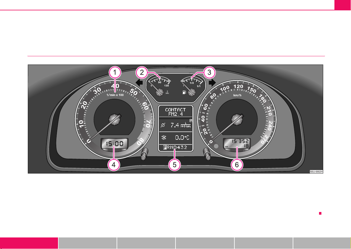
Fig. 2 Instrument cluster
Instruments and Indicator/Warning Lights 13
1
Engine revolutions counter . . . . . . . . . . . . . . . . . . . . . . . . .
2
Coolant temperature gauge . . . . . . . . . . . . . . . . . . . . . . . . .
3
Fuel gauge . . . . . . . . . . . . . . . . . . . . . . . . . . . . . . . . . . . . . .
4
Digital clock and multi-functional indicator . . . . . . . . . . . . . .
5
Information display* . . . . . . . . . . . . . . . . . . . . . . . . . . . . . . .
6
Speedometer
Using the system Safety Driving Tips General Maintenance Breakdown assistance Technical Data
14
14
14
15, 18
22
− with counter for distance driven . . . . . . . . . . . . . . . . . . .
− with trip counter for distance driven . . . . . . . . . . . . . . . .
− with Service Interval Display . . . . . . . . . . . . . . . . . . . . .
When the lights are switched on, the instrument cluster is illuminated.
16
16
16
Instruments and Indicator/Warning Lights14
A
A
A
Engine revolutions counter
The start of the red zone in the revolutions counter ⇒ page 13, fig. 2
indicates the maximum permissible engine speed for all gears for an
engine which has been run in and operating at a normal temperature. You
should shift into the next higher gear before this red zone is reached, or
move the selector lever into position D if your car is fitted with an automatic
gearbox.
One should shift to the next lower gear at the latest when the engine is no
longer running smoothly.
Avoid high engine speeds during the running-in period ⇒ page 182
Caution
The needle of the revolutions counter must on no account move into the
red zone of the scale - risk of engine damage!
For the sake of the environment
Shifting up early helps you save fuel and reduce the operating noise of
your vehicle.
1
Coolant temperature gauge
The coolant temperature gauge ⇒ page 13, fig. 2 only operates when
the ignition is switched on.
In order to avoid any damage to the engine, please pay attention to the
following notes regarding the temperature ranges:
2
Cold range
If the pointer is still in the left-hand area of the scale it means that the
engine has not yet reached its operating temperature. Avoid running at
high engine speeds, at full throttle and at severe engine loads.
The operating range
The engine has reached its operating temperature as soon as the pointer
moves into the mid-range of the scale. The pointer may also move further
to the right at high engine loads and high outside temperatures. This is not
critical provided the warning symbol
flash.
If the symbol in the instrument cluster flashes it means that either the
coolant temperature is too high or the coolant level is too low. Please
refer to the guidelines ⇒ page 31, “Coolant temperature/coolant level ”.
in the instrument cluster does not
WARNING
Pay attention to the warning notes ⇒ page 209, “Working in the
engine compartment” before opening the bonnet and inspecting
the coolant level.
Caution
Additional headlights and other attached components in front of the fresh
air inlet impair the cooling efficiency of the coolant. There is then a risk of
the engine overheating at high outside temperatures and high engine
loads!
Fuel gauge
The fuel gauge ⇒ page 13, fig. 2 only operates when the ignition is
switched on.
3
Instruments and Indicator/Warning Lights 15
The fuel tank has a capacity of about 62 litres. The warning symbol in
the instrument cluster lights up when the pointer reaches the reserve
marking. There are now about 8 litres of fuel remaining in the tank. This
symbol is a reminder for you, that you must refuel.
The following will be displayed in the information display*:
PLEASE REFUEL
A peep sounds as an additional warning signal.
Caution
Never run the fuel tank completely empty! An irregular fuel supply can
result in poor ignition or misfiring. Unburnt fuel may get into the exhaust
system and damage the catalytic converter.
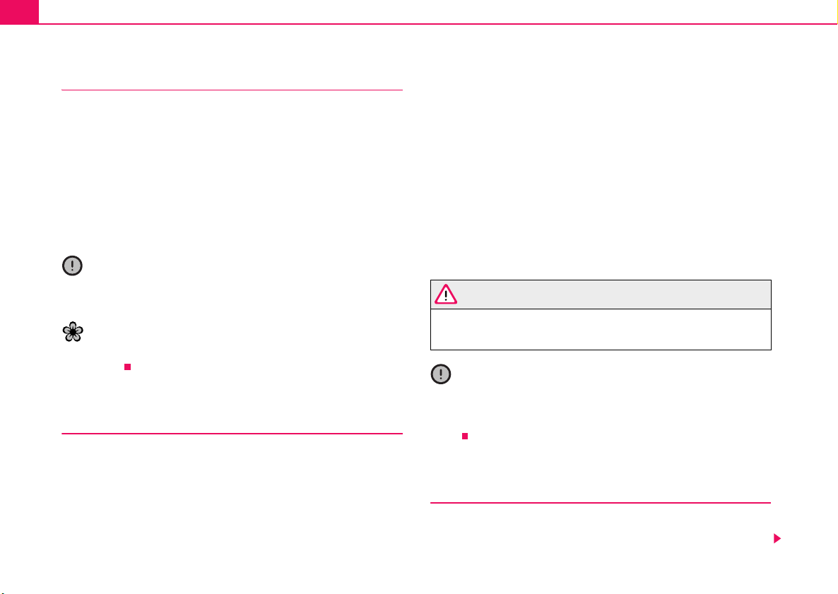
Digital clock
You can set the time with the reset button at the bottom right next
to the rev counter.
Setting clock
– Turn the reset button to the left.
Setting minutes
– Turn the reset button to the right.
WARNING
The clock should not be adjusted while driving for safety reasons
but only when the vehicle is stationary!
Fig. 3 Instrument
cluster: Digital clock
Using the system Safety Driving Tips General Maintenance Breakdown assistance Technical Data
Instruments and Indicator/Warning Lights16
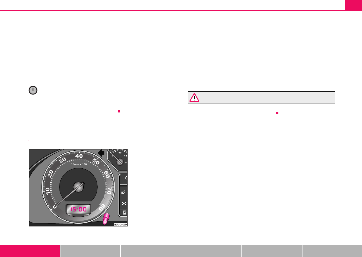
Speedometer with counter for distance
driven
Fig. 4 Instrument
cluster: Counter for
distance driven
The distance which you have driven with your vehicle is shown in kilometers (km). On certain model versions, the readout is shown in “miles”.
Bottom counter (trip counter) for distance driven
The bottom counter indicates the distance which you have driven since
this counter was last reset - in steps of 100 metres or 1/10 of a mile. It can
be reset to zero by pressing the reset button next to the trip counter
⇒ fig. 4.
Top counter for distance driven
The top counter for distance driven indicates the total distance in kilometers or miles which the vehicle has been driven.
Fault display
dEF will appear as a constant text in the display field of the counter for
distance driven if there is a fault in the instrument cluster. Have this fault
rectified without delay by a Škoda dealer.
Warning against excessive speeds*
An acoustic warning signal will sound when the vehicle speed exceeds
120 kilometres per hour. The acoustic warning signal will switch off again
when the vehicle speed goes below this speed limit.
This function is only valid for some countries.
WARNING
Never seek to adjust the trip counter for distance driven while
driving for safety reasons!
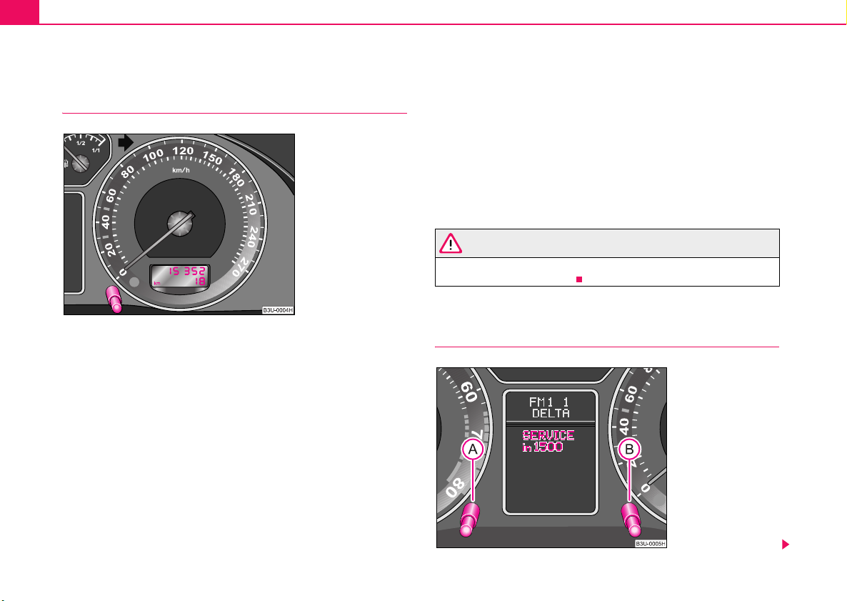
Service Interval Display
Fig. 5 Instrument
cluster: Service
Interval Display
Instruments and Indicator/Warning Lights 17
ABA
ABA
A
Depending on the equipment installed in the vehicle, the information
appears in the display of the counter for distance driven or in the information display⇒ page 16, fig. 5.
Service Interval Display
If the due date for the service is reached, the following text appears after
switching on the ignition:
in the display of the trip counter
Service 1 500 km
in information display
SERVICE in 1500 km
Prior to the due date for the service the kilometer readout decreases in
steps of 100 km. As soon as the due date for the service is reached, the
following text appears:
in the display of the trip counter
Service
in information display
Service now
The display disappears within 20 seconds after starting the engine. The
trip counter is also displayed after pressing the reset button of the trip
counter (for more than 1 second).
Resetting Service Interval Display
We recommend having this resetting performed by a Škoda Dealer.
Škoda dealer:
• resets the memory of the display after the appropriate inspection;
• makes an entry in the Service Schedule;
• affix the sticker to the side of the dash panel on the driver's side, where
the following service interval is entered.
It is also possible for you to reset the Service Interval Display with the
reset button ⇒ page 16, fig. 5 as follows (does not apply to models
with fixed service intervals - QG2).
• Switch off the ignition (if not already off), press the reset button and
hold it down.
B
• Switch the ignition on and release the reset button . The text
Service or Service now appears in the display.
• Turn the button for resetting the clock to the right - the display is
reset.
A
Caution
We recommend that you do not reset the Service Interval Display yourself
otherwise this can result in the service interval display being incorrectly
set, which may also result in problems with operation of your vehicle.
Note
• Never reset the display between service intervals otherwise this may
result in incorrect readouts.
• information is retained in the Service Interval Display also after the
battery of the vehicle is disconnected.
• it is necessary to re-code the Service Interval Display if a new instru-
ment cluster is installed during repair work. This work is carried out by a
Škoda dealer.
• After resetting the display with flexible service intervals (QG1) using
the reset button , the data displayed are the same as for a car with fixed
service intervals (QG2). We therefore recommend having the Service
Interval Display reset only by a Škoda dealer who is familiar with the
procedure for resetting the display with a vehicle system tester.
B
• Please refer to the brochure Service Schedule for extensive information
about the service intervals.
Using the system Safety Driving Tips General Maintenance Breakdown assistance Technical Data
Instruments and Indicator/Warning Lights18
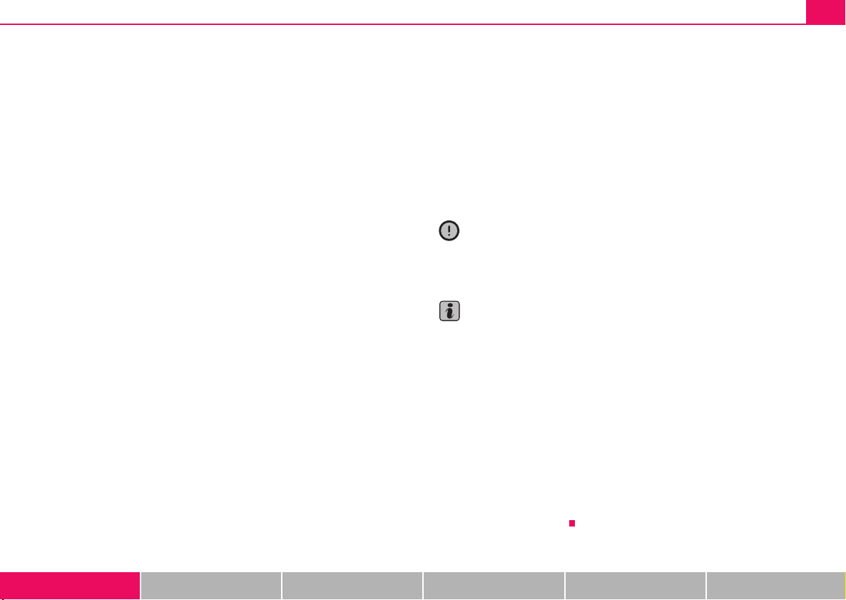
Multi-functional indicator (onboard
computer)
Introduction
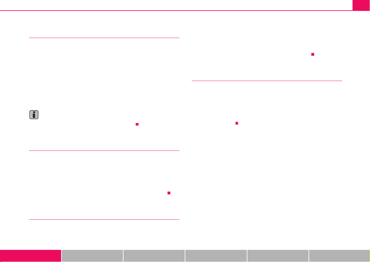
Fig. 6 Multi-functional
indicator: Average fuel
consumption
The multi-functional indicator appears in the display of the revolutions
counter ⇒ page 13, fig. 2 or in the information display ⇒ fig. 6 depending
on the equipment fitted to your vehicle.
The multi-functional indicator offers you a range of useful information.
The outside temperature ⇒ page 20
Range ⇒ page 20
Current fuel consumption ⇒ page 20
Average fuel consumption ⇒ page 21
Driving time ⇒ page 21
Distance driven ⇒ page 21
Average speed ⇒ page 21
Note
In certain national versions the displays appear in the Imperial system of
measures.
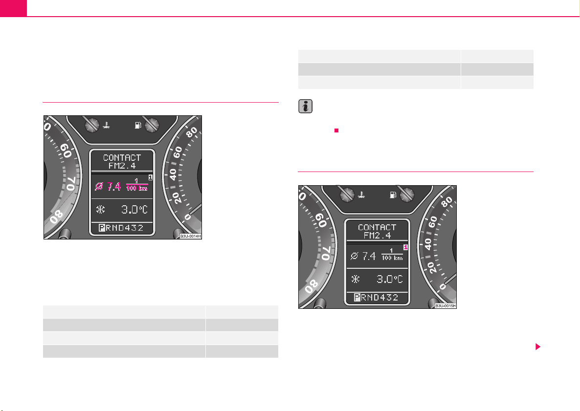
Memory
Fig. 7 Multi-functional
indicator: Memory level
The multi-functional indicator is equipped with two automatic memories.
You can see the memory which is currently being shown in the display
from the negatively displayed number ⇒ fig. 7.
Instruments and Indicator/Warning Lights 19
A
AAA
ABA
A
The data of the single-trip memory (memory 1) is shown if a 1 appears in
the display. A 2 shown in the display means that data relates to the total
distance memory (memory 2).
Switching of the memory takes place when the button ⇒ fig. 8.
Single-trip memory (memory 1)
The single-trip memory collates the driving information from the moment
the ignition is switched on until it is switched off. New data will also flow
into the calculation of the current driving information if the trip is continued
within 2 hours after switching off the ignition. The memory will be is automatically erased, on the other hand, if the trip is interrupted for more than
2 hours.
Total-trip memory (memory 2)
The total distance driven memory gathers data from any number of
indvidual journeys up to a total of 100 hours driving or 10 000 kilometres
driven. The memory is deleted when either of these limits is reached and
the calculation starts from anew.
The total-trip memory will not, contrary to the single-trip memory, be
deleted after a period of interruption of driving of 2 hours.
B
Note
All information in the memory is erased if the battery of the vehicle is
disconnected.
Using the system
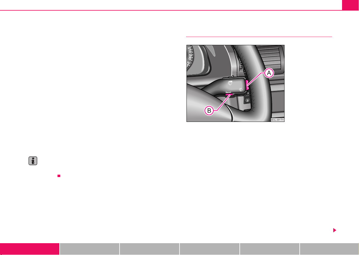
Fig. 8 Multi-functional
indicator: Controls
The rocker switch and the button are located in the grip of
the window wiper lever ⇒ fig. 8.
Selecting the memory
– Repeated short-term pressing of the button allows one to
select the individual memories.
Selecting the functions
– Press the rocker switch up or down. This will cause the
A
individual functions of the multi-functional indicator to appear
in the display one after the other.
B
Setting function to zero
– Select the memory you want.
– Press button for more than 1 second.
Using the system Safety Driving Tips General Maintenance Breakdown assistance Technical Data
B
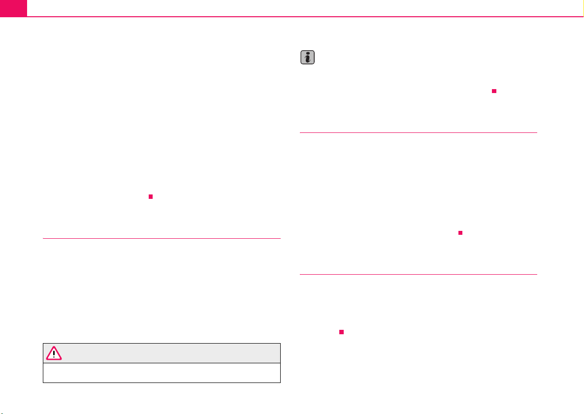
Instruments and Indicator/Warning Lights20
ABA
The following readouts of the selected memory will be set to zero by
button :
• Average fuel consumption
• Distance driven
• Average speed
• Driving time
You can only operate the multi-functional indicator when the ignition is
switched on. After the ignition is switched on, the function displayed is the
one which you last selected before switching off the ignition.
The outside temperature indicator will appear with an ice chrystal symbol
when the outside temperature lies between +5°C and -5°C. The symbol
warns the driver of the possible danger of ice on the road. After the rocker
A
switch is pressed, the function displays the one which you last selected
before switching off the ignition.
The outside temperature
The outside temperature appears in the display when the ignition is
switched on.
The correct outside temperature will be indicated with a delay of 5
minutes. If the vehicle is stationary (or driven at a very low speed) the
temperature indicated may be slightly higher than the actual outside
temperature because of heat radiated by the engine.
The outside temperature indicator will appear with an ice chrystal symbol
when the outside temperature lies between +5°C and -5°C.
Note
The outside temperature is not indicating when showing navigation data
(guidance to the destination). It must be called up over the menu (valid for
vehicles which have a navigation and information display).
Range
The estimated range in kilometres is shown on the display. It indicates the
distance you can still drive with your vehicle based on the present level of
fuel in the tank for the same style of driving. The readout is shown in steps
of 5 km.
The fuel consumption for the last 50 km is taken as a basis for calculating
the range. If you drive in a more economical manner from this moment on,
the range will be increased accordingly.
You first drive 50 km if the readout is reset (after disconnecting the battery)
before a new readout for the range is displayed.
Current fuel consumption
The current fuel consumption level is shown in the display in litres/100 km.
This information can help you to adapt your style of driving to the fuel
consumption you wish to achieve.
The display appears in litres/hour if the vehicle is stationary or driving at a
low speed.
WARNING
Please note that black ice may also be present on the road surface
even at temperatures around +5°C - warning, drive with care!
Instruments and Indicator/Warning Lights 21
A
A
A
A
Average fuel consumption
The average fuel consumption since the memory was last erased is
shown in the display in litres/100 km ⇒ page 18. This information can help
you to adapt your style of driving to the fuel consumption you wish to
achieve.
If you wish to determine the average fuel consumption over a certain
period of time you must first erase the memory at the start of the new
measurement using the button ⇒ page 19, fig. 8. A zero appears in
the display for the first 300 metres you drive after erasing the memory.
The indicated value will be updated every 30 metres while you are driving.
B
Note
The amount of fuel consumed will not be indicated.
Driving time
The driving time which has elapsed since the memory was last erased,
appears in the display ⇒ page 18. If you wish to calculate the driving time
from a particular time of day you must first erase the memory at this
moment in time by pressing the button ⇒ page 19, fig. 8.
The maximum time indicated in both switch positions is 99 hours and 59
minutes. The indicator is set back to null if this period is exceeded.
B
particular time of day you must first erase the memory at this moment in
time by pressing the button ⇒ page 19, fig. 8.
The maximum distance indicated in both switch positions is 9 999 km.
The indicator is set back to null if this period is exceeded.
B
Average speed
The average speed since the memory was last erased is shown in the
display in km/hour ⇒ page 18. If you wish to determine the average speed
over a certain period of time you must first erase the memory at the start
of the new measurement using the button ⇒ page 19, fig. 8.
A zero appears in the display for the first 100 metres you drive after
erasing the memory.
B
Distance driven
The distance driven since the memory was last erased appears in the
display ⇒ page 18. If you wish to calculate the distance driven from a
Using the system Safety Driving Tips General Maintenance Breakdown assistance Technical Data
Instruments and Indicator/Warning Lights22
Information display*
Introduction
Fig. 9 Instrument
cluster: Information
display
The information display provides you with information in a convenient way
concerning the current operating state of your vehicle. The information
system also provides you with data (depending on the equipment installed
in the vehicle) relating to the radio, multi-functional indicator, navigation
system and automatic gearbox.
Certain functions and operating conditions are always being checked on
the vehicle when the ignition is switched on and also while driving.
Functional faults, if required repair work and other information are indicated by red symbols ⇒ page 25 and yellow symbols ⇒ page 26.
Lighting up of these symbols is combined with an acoustic warning signal.
Information and texts giving warnings are also shown in the display
⇒ page 28.
The display of text is possible in the following languages:
Czech, English, German, French, Italian, Spanish, Portuguese.
You can have the relevant language set by a Škoda dealer.
The following information can be shown in the display (depending on the
equipment installed on the vehicle).
Menu ⇒ page 23
Door ajar warning, luggage compartment door and
bonnet ajar warning
Radio display ⇒ page 24
Information from the telephone ⇒ page 134
Service Interval Display ⇒ page 16
Selector lever position for an automatic gearbox ⇒ page 127
On models fitted with an automatic gearbox, the information in the display
appears only after a drive position is engaged.
⇒ page 24
Instruments and Indicator/Warning Lights 23
A
AAABA
A
Menu
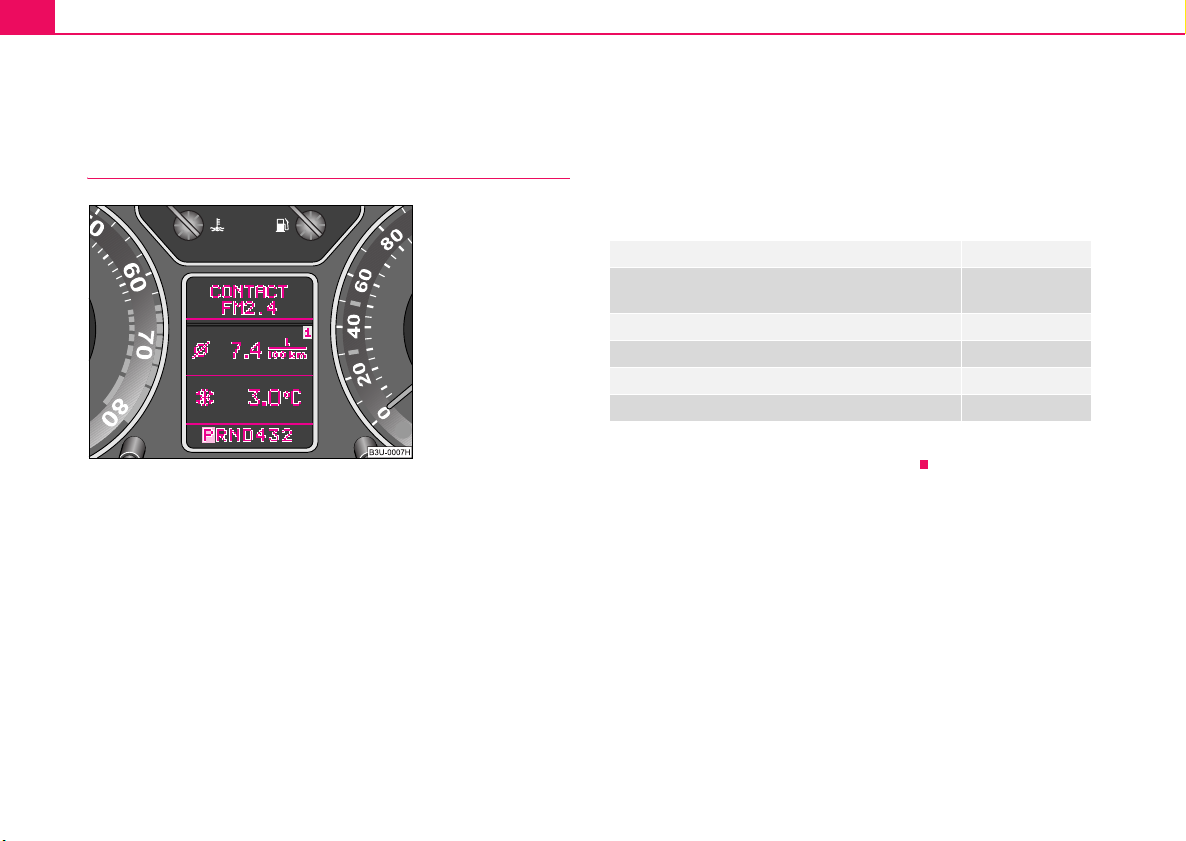
Fig. 10 Information
display: Menu
Fig. 11 Information
display: Controls
– You can select the menu through the rocker switch . The
selected information is displayed after pressing the button
for a short time or after releasing the rocker switch (after
A
about 4 seconds).
You can select the following information (depending on the equipment
installed on the vehicle):
TRIP COMPUTER (MFD) ⇒ page 18
CAR STATUS ⇒ page 24
DISPLAY OFF
NAVIGATION ⇒ page 27
After selecting the menu DISPLAY OFF the display is switched off. Press
rocker switch for at least 1 second to switch the display on again.
The Information CAR STATUSflashes in the menu if there is something
which is not in proper order on the vehicle (e.g. warning of a low fuel level).
The first warning will be displayed after switching over to CAR STATUS.
You can then display other operating conditions afterwards using the
switch-over function (such as water level low).
A
– You can activate the menu by pressing the rocker switch
A
⇒ fig. 11 for more than 1 second.
Using the system Safety Driving Tips General Maintenance Breakdown assistance Technical Data
Instruments and Indicator/Warning Lights24
Door ajar warning, luggage compartment door and
bonnet ajar warning
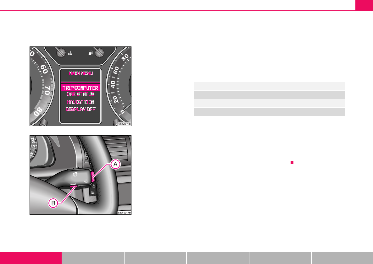
Fig. 12 Information
display: Door warning
The door, luggage compartment door and bonnet ajar warning lights up
when at least one of the three items door, luggage compartment or bonnet
are not closed when the ignition is turned on. The symbol indicates which
door is still open or whether the luggage compartment door or bonnet is
not closed ⇒ fig. 12.
The symbol goes out as soon as the doors, luggage compartment door
and bonnet are completely closed.
As an additional warning signal, a 3 time peep sounds if the car is driven
at a speed of more than 6km/hour and if the door is open.
Radio display
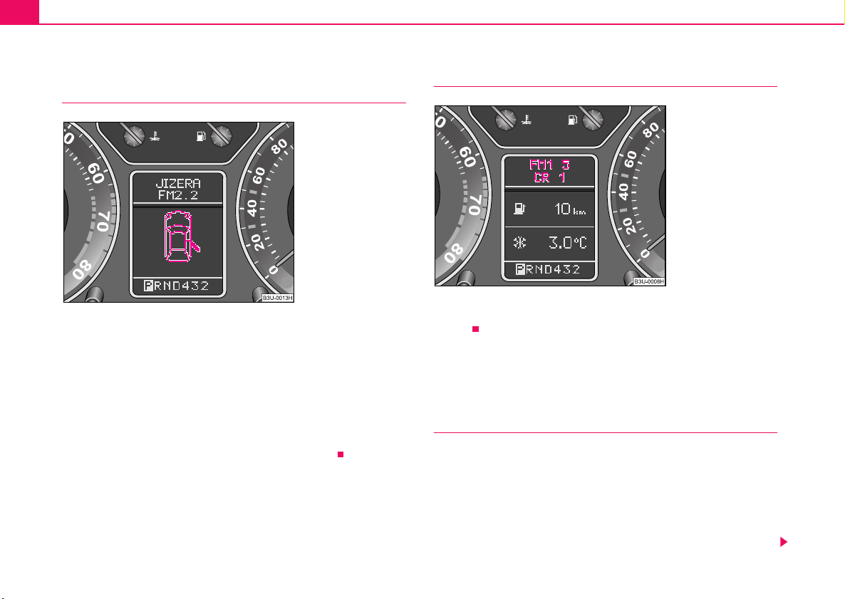
Fig. 13 Information
display: Radio display
These displays appear in addition to the normal information in the radio
display.
Auto Check Control
Vehicle condition
The Auto Check Control carries out a check of certain functions and
vehicle components. The check is performed constantly when the ignition
is switched on, both when the vehicle is stationary, as well as when
driving.
Operational faults, urgent repairs, service work or other information
appear in the display of the instrument cluster. The displays are shown
with a red or yellow light symbol depending on the priority of the message.
Instruments and Indicator/Warning Lights 25
AAA
The red symbols indicate danger (priority 1) while the yellow symbols indicate a warning (priortity 2). Information for the driver may also appear in
addition to the symbols ⇒ page 28.
Investigate the displayed faults as soon as possible. If several operational
faults exist at the same time, the symbols will appear one after the other
and are each visible for about 2 seconds.
The error messages are faded out after 10 seconds or by actuating the
rocker switch ⇒ page 23, fig. 11 and are stored under the information
CAR STATUS.
There is at least one error message to be read when the term CAR
STATUS is flashing in the main menu. The display will show STATUS 1/2
(for example) if a number of error messages are present. This display indicates that the first of a total of two error messages should be displayed.
Actuate the rocker switch , to call up the individual error messages.
If a fault occurs, a warning signal will also sound in addition to the symbol
and text in the display:
A
• Priority 1 - three warning signals
• Priority 2 - one warning signal
Operational check of the automatic gearbox
When the ignition is switched on, the Auto Check Control automatically
carries out an operational check. The following text will appear first if the
selector lever is the position P or N:
"APPLY FOOT BRAKE WHEN SELECTING GEAR WITH VEHICLE
STATIONARY." (Apply foot brake when selecting a gear while the
vehicle is stationary).
You must depress the brake pedal first and press the Shiftlock button if
you wish to move the selector lever out of these positions.
The text will disappear once you select a drive position (R, D etc.), and the
Auto Check Control function is displayed.
If the Auto Check Control detects faults, these will be displayed about 15
seconds after starting the engine in place of the text shown above. A
warning signal sounds at the same time.
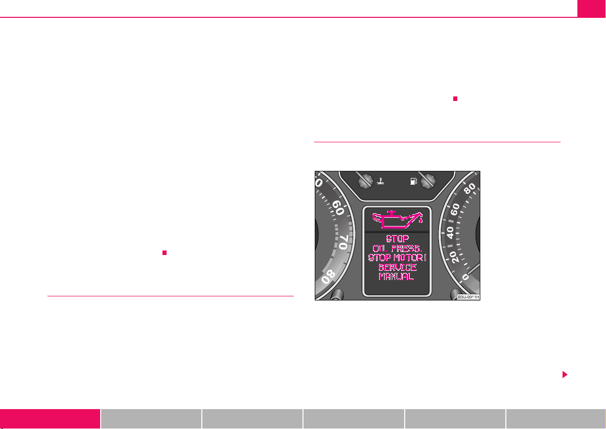
Red symbols
A red symbol signals danger.
Fig. 14 Information
display: Oil pressure is
low
Proceed as follows if a red symbol is displayed:
– Stop the vehicle.
– Switch the engine off.
– Investigate the function indicated.
Using the system Safety Driving Tips General Maintenance Breakdown assistance Technical Data
Instruments and Indicator/Warning Lights26
– Obtain professional assistance.
Meaning of the red symbols:
Faults in the brake surface ⇒ page 35
Coolant level too low/coolant tempera-
ture too high
Engine oil pressure too low ⇒ page 32
Three successive warning signals will sound if a red symbol appears. The
symbol continues flashing until the fault is rectified.
If several operational faults of priority 1 exist, the symbols appear one after
the other and are each illiminated for about 2 seconds.
⇒ page 31
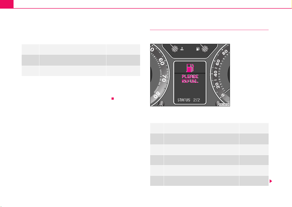
Yellow symbols
A yellow symbol signals a warning.
The meaning of the yellow symbols:
Fuel level low ⇒ page 32
Check engine oil level, engine oil sensor
faulty
Brake pad worn ⇒ page 32
Washer fluid level low ⇒ page 33
Light bulb defect ⇒ page 33
Light bulb in the brake light defect ⇒ page 33
Fig. 15 Information
display: Fuel level low
⇒ page 32
One warning signal will sound if a yellow symbol appears.
If several operational faults of priority 2 exist, the symbols appear one after
the other and are each illiminated for about 2 seconds.
Check the relevant function as soon as possible.
Navigation system*
The controls for the navigation system, radio, CD player are located in the
centre console on both sides of the monitor screen. Navigation data is
also shown in the information display of the instrument cluster.
Information and warning texts are displayed preferentially when the navigation system is switched on.
Operation of the navigation system is described in separate operating
instructions to be found in the on-board literature.
Instruments and Indicator/Warning Lights 27
Using the system Safety Driving Tips General Maintenance Breakdown assistance Technical Data
Instruments and Indicator/Warning Lights28
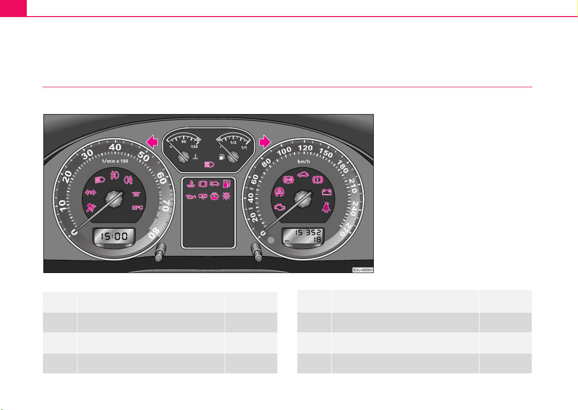
Warning lights
An overview
The warning lights indicate certain functions or faults.
Fig. 16 Instrument cluster with warning lights
Turn signal lights (to the left)
Turn signal lights (to the right)
Main beam
Airbag system
⇒ page 29
⇒ page 29
⇒ page 30
⇒ page 30
Turn signal system for vehicles towing a
trailer
Low beam
Fog lights
Rear fog light
⇒ page 30
⇒ page 30
⇒ page 31
⇒ page 31
Instruments and Indicator/Warning Lights 29
EPC fault light (petrol engine)
Glow plug system (diesel engine)
Coolant temperature/coolant level
Brake pad wear
Bonnet
Fuel reserve
Engine oil
Open door
Fluid level in windshield washer system
Bulbs
Control system for exhaust
Electronic stability programme (ESP)*
Traction control system (TCS)*
Antilock brake system (ABS)
Electronic immobiliser
⇒ page 31
⇒ page 31
⇒ page 31
⇒ page 32
⇒ page 32
⇒ page 32
⇒ page 32
⇒ page 33
⇒ page 33
⇒ page 33
⇒ page 34
⇒ page 34
⇒ page 34
⇒ page 34
⇒ page 35
Brake system
Dynamo
Seat belt warning light
WARNING
⇒ page 35
⇒ page 36
⇒ page 36
• If you do not pay attention to the warning lights coming on and
the corresponding descriptions and warning notes, this may result
in severe body injuries or major vehicle damage.
• The engine compartment of your car is a hazardous area. There
is a risk of injuries, scalding, accidents and fire when working in the
engine compartment, e.g. inspecting and replenishing oil and other
fluids. It is also essential to observe all warnings ⇒ page 209.
Note
• Arrangement of the indicator lights depends on the model and model
version. The symbols shown in the following functional description are to
be found as indicator lights in the instrument cluster.
• Operational faults are shown in the display of the instrument cluster as
red symbols (priority 1 - danger) or yellow symbols (priority 2 - warning).
Turn signal system
Either the left or right indicator light flashes depending on the position of the turn signal lever.
The indicator light flashes at twice its normal rate if a turn signal light fails.
This does not apply when towing a trailer.
Using the system Safety Driving Tips General Maintenance Breakdown assistance Technical Data

Instruments and Indicator/Warning Lights30
Switching off the hazard warning light system is switched on will cause all
of the turn signal lights as well as both indicator lights to flash.
Further information about the turn signal system ⇒ page 59.
Main beam
The indicator light comes on when the main beam is selected or also
when the headlight flasher is operated.
Further information about the main beam ⇒ page 59.
Airbag system
Monitoring the airbag system
The warning light comes on for a few seconds when the ignition is
switched on.
There is a fault in the system if the warning light does not go out or comes
on or flashes while driving ⇒ . This also applies if the warning light
does not come on when the ignition is switched on.
The following text will be displayed in the information display*:
AIRBAG FAULT
The functionality of the airbag system is also monitored electronically,
when one airbag has been switched off
Front, side or head passenger airbags which have been switched off
by a Škoda dealer using the vehicle system tester:
• The warning light lights up for 3 seconds after switching on the igni-
tion and then flashes for 12 seconds afterwards in 2 second intervals.
Front, side or head passenger airbags which have been switched off
using the switch (for switching off airbags)* in the storage compartment on the front passenger side:
• The warning light comes on for 3 seconds after the ignition has
been switched on.
• Switching off airbags is indicated in the middle of the dash panel by the
lighting up of the indicator light (airbag switched off)
⇒ page 162.
WARNING
Have the airbag system checked immediately by a Škoda dealer if
a fault exists. Otherwise, there is a risk of the airbag not being activated in the event of an accident!
Note
Further information about switching off airbags ⇒ page 161, “Deactivating
an airbag”.
Turn signal system for vehicles towing trailer
The indicator light on vehicles towing a trailer flashes together with the
respective indicator light for the turn signal system.
The indicator light
on the vehicle is not operating.
Low beam
The indicator light comes on when low beam is selected ⇒ page 56.
does not flash if a turn signal light on the trailer or

Instruments and Indicator/Warning Lights 31
Fog lights
The warning light comes on when the fog lights are operating
⇒ page 57.
The rear fog light
The warning light comes on when the rear fog lights are operating
⇒ page 57.
EPC fault light (petrol engine)
The (Electronic Power Control) warning light comes on for a few
seconds when the ignition is switched on.
There is a system fault in the engine control system if the warning light
does not go out or comes on or flashes while driving. The engine management system selects an emergency programme which enables you to
drive to the nearest Škoda dealer while adopting a gentle style of driving.
The following text will be displayed in the information display*:
ENGINE WORKSHOP! (ENGINE FAULT WORKSHOP!)
Glow plug system (diesel engine)
The indicator light lights up for a cold engine when switching on the
igntion (pre-heat position) 2 ⇒ page 117. Start the engine just as soon as
the indicator light goes out.
The glow plug indicator light will come on for about 1 second if the engine
is at a normal operating temperature or if the outside temperature is
above +5°C. This means that you can start the engine right away.
There is a fault in the glow plug system if the indicator light does not
come on at all or lights up continuously. Contact as soon as possible a
Škoda Dealer to obtain professional assistance.
The following text will be displayed in the information display*:
ENGINE WORKSHOP! (ENGINE FAULT WORKSHOP!)
Coolant temperature/coolant level
The warning light comes on for a few seconds 1) when the ignition is
switched on.
The coolant temperature is too high or the coolant level too low if the
warning light does not go out after the engine is started or flashes while
driving.
3 peeps sound as an additional warning signal.
In this case stop and switch the engine off and check the coolant level;
top up the coolant as necessary.
Do not continue your journey if for some reason it is not possible under
the conditions prevailing to top up with coolant. Keep the engine
switched off and obtain professional assistance from a Škoda dealer.
If the coolant is within the specified range, the increased temperature may
be caused by an operating problem at the coolant fan. Check the fuse for
the coolant fan, replace it if necessary ⇒ page 250, “Replacing fuses”.
1)
The warning light on vehicles fitted with information display does not come on
after switching the ignition on, but only if the coolant temperature is too high or the
coolant level is too low.
Using the system Safety Driving Tips General Maintenance Breakdown assistance Technical Data

Instruments and Indicator/Warning Lights32
Do not continue driving if the warning light does not go off although the
fluid is at the correct level and also the fuse of the fan is in proper order.
Contact a Škoda dealer to obtain assistance.
Please also refer to the additional instructions ⇒ page 216, “Replenishing
the coolant”.
The following text will be displayed in the information display*:
STOP CHECK COOLANT SERVICE MANUAL (STOP! CHECK
COOLANT! OWNER'S MANUAL)
WARNING
• Take care when opening the coolant expansion bottle. If the
engine is hot, the cooling system is pressurized - risk of scalding!
It is best to allow the engine to cool down before removing the cap.
• Do not touch the coolant fan! The coolant fan may switch on
automatically even if the ignition is off.
Brake pad wear
If the warning light comes on, contact a Škoda Dealer and have the
brake pads of all the wheels inspected.
A peep sounds as an additional warning signal.
The following text will be displayed in the information display*:
CHECK BRAKE PADS
Bonnet
The warning light comes on when the ignition is switched on if the
bonnet is unlocked.
Fuel reserve
The warning light comes on if the fuel level in the tank has dropped to
about 8 litres.
A peep sounds as an additional warning signal.
The following text will be displayed in the information display*:
PLEASE REFUEL
Engine oil
The warning light lights up red (low oil pressure)
The warning light comes on for a few seconds
switched on.
Stop the vehicle and switch the engine off if the warning light does not
go off after the engine has started or flashes while driving. Check the oil
level and top up with oil as necessary ⇒ page 213.
3 peeps sound as an additional warning signal.
2)
when the ignition is
2)
The warning light on vehicles fitted with information display does not come on
after switching the ignition on, but only if a fault exists or the engine oil level is too
low.

Instruments and Indicator/Warning Lights 33
Do not continue your journey if for some reason it is not possible under
the conditions prevailing to top up with oil. Keep the engine switched off
and obtain professional assistance from a Škoda dealer.
Do not drive any further if the warning light remains on even if the oil is
at the correct level. Do not run the engine not at idling speed either.
Contact the nearest Škoda dealer to obtain professional assistance.
The following text will be displayed in the information display*:
STOP! OIL PRESS. STOP MOTOR! SERVICE MANUAL (STOP! OIL
PRESSURE STOP ENGINE! SERVICE MANUAL)
The warning light lights up yellow* (insufficient oil)
If the warning light lights up yellow, there is not the correct quantity of oil
in the engine. Check as soon as possible the oil level or top up
⇒ page 213 with engine oil.
A peep sounds as an additional warning signal.
The following text will be displayed in the information display*:
CHECK OIL LEVEL
The warning light will go out if the bonnet is left open for more than 30
seconds. If no engine oil has been replenished, the warning light will come
on again after driving about 100 km.
The warning light
A fault on the engine oil level sensor is indicated additionally by an audible
signal and the warning light coming on several times after the ignition has
been switched on.
In this case have the engine inspected without delay by a Škoda
dealer.
The following text will be displayed in the information display*:
OIL SENSOR WORKSHOP!
flashes yellow* (engine oil level sensor faulty)
WARNING
The red oil pressure light is not an oil level indicator! One
should therefore check the oil level at regular intervals, preferably
after every refueling stop.
Open door
The warning light comes on if one or several doors are opened or if the
boot lid is opened.
Windshield washer fluid level
The warning light comes on when the ignition is switched on if there is
insufficient fluid in the windshield washer system. Top up the fluid
⇒ page 223.
A peep sounds as an additional warning signal.
The following text will be displayed in the information display*:
TOP UP WASH FLUID
Bulbs
The warning light comes on if a light bulb is damaged:
• brakes applied (brake light)
• in lighting (low beam and/or rear light)
A peep sounds as an additional warning signal.
Using the system Safety Driving Tips General Maintenance Breakdown assistance Technical Data

Instruments and Indicator/Warning Lights34
The following text will be displayed in the information display*:
LIGHTS FAILURE
or
BRAKE LIGHTS FAILURE
Control system for exhaust gases
The warning light comes on after the ignition has been switched on.
If the warning light does not go out after starting the engine or it lights up
or flashes when driving, a fault exists in an exhaust relevant component.
The engine management system selects an emergency programme
which enables you to drive to the nearest Škoda dealer while adopting a
gentle style of driving.
The following text will be displayed in the information display*:
EMISSIONS WORKSHOP!
Electronic Stability Programme (ESP)*
The warning light comes on for a few seconds when the ignition is
switched on.
Components of the ESP system also include the Traction Control System
(TCS), Electronic Differential Lock (EDL), the Antilock Brake System ABS
and the braking assistant
The warning light comes on when driving when a control cycle is activated.
The warning light will come on and remains on if the ESP is switched off
or if there is a fault in the system.
The fact that the ESP system operates together with the ABS means that
the ESP warning light will also come on if the ABS system is not operating
properly.
Further information on the ESP ⇒ page 175, “Electronic stability
programme (ESP)*”.
Traction Control System (TCS)*
The warning light comes on for a few seconds when the ignition is
switched on.
The warning light comes on when driving when a control cycle is activated.
The warning light will come on and remains on if the TCS is switched off
or if there is a fault in the system.
The fact that the TCS system operates together with the ABS means that
the TCS warning light will also come on if the ABS system is not operating
properly.
Further information about the TCS ⇒ page 176, “Traction control system
(TCS)*”.
Antilock brake system (ABS)
The warning light shows the functionality of the ABS and the Electronic
Differential Lock (EDS).

Instruments and Indicator/Warning Lights 35
The warning light comes on for a few seconds after the ignition has been
switched on or when starting the engine. The warning light goes out after
an automatic check sequence has been completed.
A fault in the ABS
The system is not functioning properly if the warning light
out within a few seconds after switching on the ignition, does not light up
at all or lights up while driving. The vehicle will only be braked by the
normal brake system without the effect of the ABS function. Visit a Škoda
dealer as quickly as possible and adjust your style of driving in the meantime since you will not know how great the damage is.
Three additional warning tones will sound if there is a major fault in the
ABS.
Further information about ABS ⇒ page 179, “Antilock brake system
(ABS)”.
A fault in the entire brake system
If the ABS warning light
warning light (handbrake must be released), there is a fault not only in
the ABS but also in another part of the brake system⇒ .
The following text will be displayed in the information display*:
STOP BRAKE FAULT SERVICE MANUAL
Electronic Differential Lock (EDL)
The EDL is a part of the ABS. A fault in the EDL is indicated by the ABS
warning light
without delay by a Škoda dealer. Further information on the
EDL⇒ page 177.
in the instrument cluster. Have the vehicle inspected
comes on together with the brake system
does not go
WARNING
• If the brake system warning light comes on together with the
ABS warning light stop the vehicle immediately and check the
WARNING (continued)
brake fluid level in the reservoir⇒ page 217, “Brake fluid” . If the
brake fluid level has dropped below the MIN marking, do not drive
any further - risk of accident! Contact a Škoda dealer to obtain
professional assistance.
• Pay attention to the following instructions⇒ page 209,
“Working in the engine compartment” before checking the brake
fluid level and opening the bonnet.
Electronic immobiliser
Data is compared between the ignition key and the control unit when
switching on the ignition. The indicator light will light up for a few
seconds when ignition key authorisation is confirmed.
The warning light will start flashing continuously if a non-authorised ignition key (for example the wrong ignition key) has been used. The engine
cannot be started ⇒ page 40.
It is only possible to start the engine of the vehicle with a Genuine Škoda
key with the matching code.
Brake system
The warning light flashes or comes on if the brake fluid level is too low,
if there is a fault in the ABS or if the handbrake is applied.
If the warning light flashes (handbrake is not applied), stop and check
the brake fluid level ⇒ .
Using the system Safety Driving Tips General Maintenance Breakdown assistance Technical Data

Instruments and Indicator/Warning Lights36
The following text will be displayed in the information display*:
STOP BRAKE FLUID SERVICE MANUAL
If there is a fault in the ABS which also influences the function of the
normal brake system (e.g. distribution of brake pressure), the ABS
warning light comes on together with the brake system warning light
. Be aware that not only the ABS but also another part of th brake
system is defective ⇒ .
3 peeps sound as an additional warning signal.
One should get used to high pedal forces, long braking distances and long
free play of the brake pedal when driving to the next Škoda dealer.
The following text will be displayed in the information display*:
STOP BRAKE FAULT SERVICE MANUAL
For further information on the brake system ⇒ page 178, “Brakes”
Handbrake applied
The warning light
warning is also given if you drive the vehicle for at least 3 seconds at a
speed of more than 6 km/h.
The following text will be displayed in the information display*:
HANDBRAKE ON
also comes on if the handbrake is applied. An audible
WARNING
• Pay attention to the following instructions ⇒ page 209,
“Working in the engine compartment”before checking the brake
fluid level and opening the bonnet.
• If the brake system warning light does not go out a few
seconds after switching on the ignition or comes on when driving,
stop immediately and check the brake fluid in the
reservoir⇒ page 217, “Brake fluid”. If the fluid level has dropped
WARNING (continued)
below the MIN marking, do not drive any further - risk of accident!
Contact a Škoda dealer to obtain professional assistance.
Dynamo
The warning light comes on after the ignition has been switched on. It
should go out after the engine has started.
If the warning light does not go out after the engine has started, or comes
on when driving, drive to the nearest Škoda Dealer. The vehicle battery
will be discharged in this case so switch off all non-essential electrical
components.
The following text will be displayed in the information display*:
ALTERNATOR WORKSHOP!
Caution
If the warning light comes on when driving and in addition the warning
light (cooling system fault) also comes on in display, you must then
stop the car immediately and switch the engine off - risk of engine
damage!
Seat belt warning light
The warning light comes on for a few seconds after the ignition is
switched on as a reminder to fasten the seat belt.
If you do not fasten the seat belt, a long warning signal sounds for 6
seconds.

For further information on the seat belts ⇒ page 145.
The following text will be displayed in the information display*:
FASTEN SEATBELT
For further information on the seat belts ⇒ page 145, “Seat belts”.
Instruments and Indicator/Warning Lights 37
Using the system Safety Driving Tips General Maintenance Breakdown assistance Technical Data

Unlocking and locking38
A
ABA
Unlocking and locking
Keys
Description
Fig. 17 Set of keys
Fig. 18 Folding key
– Press the unlock button ⇒ fig. 18 in order to open and close
the folding key.
Your car is supplied with two master keys ⇒ fig. 17 as well as a service
key and a key ring . The master keys fit in all vehicle locks. The
service key can be used only to open the doors and to start the engine.
The service key is intended, for example, to be handed over with your car
when it goes for a service, or when you arrive at the hotel.
Key ring
The key ring only has the key number on it which is essential for producing
other keys. This number can be used to order replacement keys from
Škoda dealers.
The key ring with the number should be separately and securely kept in
safe keeping since keys can only be replaced if they are lost or damaged
C
A

Unlocking and locking 39
A
by giving this number. You should also therefore give this key ring to the
purchaser when selling the vehicle.
WARNING
• Always withdraw the key whenever you leave the vehicle - even
if it is only for a short time. This is particularly important if children
are left in the vehicle. The children might otherwise start the engine
or operate electrical equipment (e.g. power windows) - risk of
injury!
• Do not withdraw the ignition key from the ignition lock until the
vehicle has come to a stop. The steering lock might otherwise
engage unintentionally - risk of accident!
Caution
• Each key contains electronic components; therefore protect them
against moisture and severe shocks.
• Keep the groove of the keys absolutely clean as impurities (textile
fibres, dust etc.) have a negative effect on proper operation of the keys
and the ignition lock.
Note
Please approach a Škoda dealer if you lose a key since he can obtain a
new one for you.
Changing the key battery
Fig. 19 Disconnect key
with radio remote
control
Fig. 20 Cover of the
transmitter housing
Each master key contains a battery which is housed in the cover
B
of the transmitter housing ⇒ fig. 19. We recommend that you
have the batteries of the key replaced by a Škoda dealer. You
Using the system Safety Driving Tips General Maintenance Breakdown assistance Technical Data

Unlocking and locking40
AAA
should, however, proceed as follows if you wish to replace the
battery yourself:
– Fold open the key.
– Use a screwdriver to carefully lever off the front part of the key
⇒ page 39, fig. 19 from the transmitter housing .
B
– Take off the cover of the transmitter housing ⇒ page 39,
fig. 20 in direction of arrow.
– Take the used battery out of the housing cover.
– Insert the new battery. Ensure that the “+” symbol on the
battery is facing downwards. The correct polarity is also
shown on the cover of the transmitter housing.
– Insert cover with battery in place at the rear of the transmitter
housing and press both parts together.
– Insert the transmitter housing into the front part of the key so
that the two parts lock into each other.
For the sake of the environment
Dispose of an old battery in accordance with environmental regulations.
Note
• The replacement battery must have the same specification as the orig-
inal battery.
• If it is still not be possible to unlock or lock the vehicle with the remote
control even after replacing the battery this means that the system has to
be synchronised ⇒ page 48.
Electronic immobiliser
The electronic immobiliser prevents the vehicle being
operated by an unauthorised person.
An electronic chip is integrated in the head of the key. The immobiliser is
deactivated with the aid of this chip when the key is inserted in the ignition
lock. The electronic immobiliser is automatically activated when you withdraw the ignition key from the lock.
Note
It is only possible to start the engine of your car with a Genuine Škoda key
with the matching code ⇒ page 35.

Unlocking and locking 41
Child safety locks
The child safety lock prevents the rear door from being
opened from the inside.
Fig. 21 Child safety
locks on the rear doors
The rear doors are equipped with a child safety lock. You can
switch the child safety lock on and off using the vehicle key.
Switching child safety lock on
– Use the vehicle key to turn the slit in the rear door to the left in
the direction of the arrow ⇒ fig. 21.
Switching child safety lock off
– Use the vehicle key to turn the slit to the right against the direc-
tion of the arrow.
So long as the child safety lock is switched on it is not possible to open the
door from the inside with the door opening lever. In this case the door can
be opened only from the outside.
Central locking system
Description
Unlocking or locking the vehicle causes all doors to be unlocked or locked
at the same time by the central locking system. The boot lid is unlocked
when opening. It can be opened by pressing the hand grip above the
licence plate.
Operation of the central locking system is possible:
• from the outside using the vehicle key ⇒ page 43
• using the buttons for the central locking system ⇒ page 44
• by using the radio remote control ⇒ page 46
Convenience operation of windows
One can open and close the electrically powered windows when unlocking
and locking the vehicle ⇒ page 52, “Convenience operation of windows”.
The electric sliding/tilting roof* can only be closed by the central locking
system.
Opening a single door*
This function allows one to just unlock the driver's door. The other doors
remain locked and are only unlocked when the command is repeated.
The single door opening function can be first activated by recoding the
control unit of the central locking system. This work is undertaken by a
Škoda dealer which can give you more information.
Using the system Safety Driving Tips General Maintenance Breakdown assistance Technical Data

Unlocking and locking42
Automatic locking*
All the doors and the boot lid are locked automatically once the car
reaches a speed of about 15 km/h.
If the ignition key is withdrawn, the car is then automatically unlocked
again. In addition, it is possible for the driver to unlock the car by pressing
the central locking button
If you wish, your Škoda Dealer can convert the central locking system of
your car to the automatic locking mode.
or by pulling the door opening lever.
WARNING
Locking the doors prevents involuntary opening in an exceptional
situation (an accident). Locked doors prevent unwanted entry into
the vehicle from outside, for example at road crossings. Locked
doors do, however, make it more difficult for rescuers to get into
the vehicle in an emergency - danger to life!
Note
• After unlocking the vehicle see, if the securing knobs are located on all
doors at the bottom.
• In the event of an accident in which the airbags are deployed, the
locked doors are automatically unlocked in order to enable rescuers to
gain access to the vehicle.
• Should the central locking system not operate properly, you can lock
and unlock the front doors and the boot lid with the key. Emergency
unlocking of fuel filler flap ⇒ page 207.
Safe securing
The central locking system is equipped with a safe securing system.
Locking the vehicle from the outside causes the door locks to be automatically blocked. It is not possible to pull out the locking buttons. The indicator light in the driver's door flashes. It is not possible to open the doors
with the door handle either from the inside or from the outside. This acts
as an effective deterrent for attempts to break into your vehicle.
You can deactivate the safe securing system. This is done by locking the
vehicle with the key or radio-operated key twice within 2 seconds.
Deactivating the safe securing system means that the warning light next
to the securing knob in the driver's door will not flash. This is not the case,
however, for an activated anti-theft alarm system* since the indicator light
is showing that the system is active ⇒ page 48.
The safe securing system is again activated the next time the vehicle is
unlocked and locked again.
The doors can be opened from the inside if the vehicle is locked and the
safe securing system is deactivated:
• The door is unlocked by actuating the door-opening lever.
• The door opens upon actuating the door-opening lever again.
WARNING
If the vehicle is locked from the outside and the safe securing
system is activated, there must not be any person and animals in
the vehicle as it is then not possible to open either a door or a
window from the inside. The locked doors make it more difficult for
rescuers to get into the vehicle in an emergency - hazard!

Unlocking and locking 43
A
A
Note
The anti-theft alarm system is also armed when the car is closed without
activating the safe securing system. In this case, always switch off the
interior monitoring sensor* ⇒ page 49 first of all to avoid an alarm being
triggered unintentionally.
Unlocking the vehicle using the key
Fig. 22 Turning the key
for unlocking and
locking the vehicle
– Turn the key in the lock of the driver's door to the left into the
opening position ⇒ fig. 22.
– Pull on the door handle and open the door.
A
• The safe securing system is deactivated.
• The windows are opened provided the key is held in the opening posi-
tion.
• The indicator light in the driver's door stops flashing if the vehicle is not
fitted with an anti-theft alarm system* ⇒ page 48.
Note
If the vehicle is equipped with an anti-theft alarm system*, you must
unlock the vehicle by inserting the key into the driver door you then have
to insert the key into the ignition lock and switch the ignition on within 15
seconds after opening the door. The alarm will be triggered if you do not
switch on the ignition within 15 seconds.
Closing the vehicle with the key
– Turn the key in the lock of the driver door to the right into the
closing position ⇒ fig. 22.
B
• All doors and the boot lid are locked (the securing knobs must move
downwards).
• The switched on interior lights go out over the door contact.
• The windows and the electric sliding/tilting roof* are closed provided
the key is held in the locking position.
• The safe securing system is activated immediately.
• The indicator light in the driver door begins flashing.
• All doors are unlocked (the securing knobs must move upwards).
• The boot lid is then unlocked.
• The switched on interior lights come on over the door contact.
Using the system Safety Driving Tips General Maintenance Breakdown assistance Technical Data
Note
The opened driver door cannot be locked. It must be locked separately
after closing it.

Unlocking and locking44
AAA
AAABABACA
A
Buttons for central locking
Fig. 23 Inner part of
driver door: Buttons for
central locking
Fig. 24 Inner part of
driver door: Switches
for opening fuel filler
flap and boot lid
All the doors ar unlocked or locked using the buttons and .
The buttons also operate if the ignition is switched off, but not if
the vehicle was locked from outside.
B
Locking all doors and the boot lid
– Press button ⇒ fig. 23.
Unlocking all doors and the boot lid
– Press button ⇒ fig. 23. If the boot lid has been set to the
permanent locking mode, it is then not unlocked ⇒ page 45
when the button is pressed.
Unlocking fuel filler flap
– Pull the switch ⇒ fig. 24.
Unlocking the boot lid
– Pull the switch ⇒ fig. 24.
Blocking boot lid remote release button
D
– Turn the master key in the lock in direction of arrow ⇒ fig. 24.
– The boot lid is unlocked by turning the key in the opposite
direction of the arrow.
Lock the boot lid from outside the vehicle ⇒ page 45.
The following applies if you have locked your vehicle using the central
locking system ⇒ fig. 23:
A
• It is not possible to open the doors or the boot lid from the outside
(safety feature, e.g. when stopping at traffic lights etc.).
• You can unlock the doors individually from the inside and open them
by pulling the door opening lever.
• Once the driver door is opened it cannot be locked again (after oper-
ating the lock function in the button for the central locking switch) in order
to avoid inadvertently being locked out of the vehicle. You then have to
lock a door separately after closing it.

Unlocking and locking 45
• In the event of an accident in which the airbags are deployed, the
locked doors are automatically unlocked from the inside in order to enable
rescuers to gain access to the vehicle.
WARNING
The central locking system also operates if the ignition is switched
off. All the doors and the boot lid are locked. Children should never
be left unattended in the vehicle since it is difficult to provide
assistance from the outside when the doors are locked. Locked
doors make it difficult for rescuers to get into the vehicle in an
emergency - hazard!
Note
The door opening lever and the button for the central locking system do
not operate if the safe securing system is activated.
Boot lid
Fig. 25 Positions of
lock cylinder of boot lid
lock
Fig. 26 Handle of boot
lid
Using the system Safety Driving Tips General Maintenance Breakdown assistance Technical Data

Unlocking and locking46
A
A
Open boot lid
– Press on the handle ⇒ page 45, fig. 26 and at the same time
raise the boot lid.
Close the boot lid
– Pull the boot lid down and close it with a slight swing ⇒ .
Permanently locking boot lid
If you turn the master key to the right ⇒ page 45, fig. 25 and withdraw
it when the lock cylinder is in the vertical position, the boot lid is no longer
incorporated in the central locking system and remains locked all the time.
It is now only possible to open the boot lid using the unlock button of
the remote control.
After turning the lock cylinder back into the horizontal position, the boot lid
is again integrated in the central locking system.
Unlocking and opening boot lid
When you turn the master key to the left ⇒ page 45, fig. 25 into the
vertical position of the lock cylinder, the boot lid jumps open. You cannot
withdraw the key in this position.
After turning the key back into the horizontal position of the lock cylinder,
the boot lid is again integrated in the central locking system, and the key
can be withdrawn.
It is recommended to always operate ⇒ page 46 the boot lid using the
remote control.
B
A
WARNING
• Ensure that the lock is properly engaged after closing the boot
lid. Otherwise, the boot lid might open suddenly when driving even
if the lock is closed - risk of accident!
WARNING (continued)
• Never drive with the boot lid slightly ajar or even fully opened
otherwise exhaust gases may get into the interior of the vehicle risk of poisoning!
Note
After closing the boot lid, it is automatically locked within 5 seconds
and the anti-theft alarm system* is activated. This applies only if the
vehicle was locked before closing the boot lid.
Remote control
Description
You can use the remote control:
• to unlock and lock the car
• unlocking boot lid
• Opening and closing window
The transmitter with the battery is housed in the handle of the master key.
The receiver is located in the interior of the car. The operating range of the
remote control is 10 metres but this range can be reduced if the batteries
are waek.
The master key has a fold-open key bit which can be used for unlocking
and locking the car manually and also for starting the engine.
If a lost key is replaced or if the receiver unit has been repaired or a new
unit installed, it is then necessary for a Škoda Dealer to initialise the
system. Only after this is it possible to again use the remote control.

Unlocking and locking 47
AAABACA
A
A
Note
• The remote control is automatically deactivated when the ignition is
switched on.
• The operation of the remote control may temporarily be affected by
interference from transmitters close to the car and which operate in the
same frequency range (e.g. mobile phone, TV transmitter).
• The battery must be replaced, ideally by the Škoda dealer, if the
central locking or anti-theft alarm system does react to the remote control
at less than 3 metres away.
Unlocking and locking car
Fig. 27 Key: Assignment of buttons
Unlocking the vehicle
– Press button ⇒ fig. 27 for about 1 second.
Locking the vehicle
– Press button for about 1 second.
Boot lid remote release
– Press button for about 1 second.
Deactivating safe securing system
– Press button zwice in 2 seconds. Further information
B
⇒ page 42.
The turn signal lights flash twice as confirmation that the vehicle has been
unlocked. If you unlock the car with button but do not open a door or
the boot lid within the next 30 seconds, the car locks again automatically.
This function is intended to prevent the car being unlocked unintentionally.
The safe securing system along with the anti-theft alarm system* are,
however, deactivated during these 30 seconds.
If the single door opening function has been activated on your car, you
unlock only the driver door by pressing button once and the complete
vehicle by pressing the button twice ⇒ page 41.
In addition, when the car is unlocked, the power seats and exterior mirrors
move into the position assigned to this key. The stored setting of driver
seat and exterior mirrors is retrieved automatically.
When the vehicle is unlocked or locked, the interior lights in the door
contact are automatically switched on or off.
The turn signal lights flash once to confirm that the vehicle has been
correctly locked. If the turn signal lights do not flash, check the doors,
bonnet and boot lid again to ensure that they are closed. If the doors, the
bonnet or the boot lid remain open when the anti-theft alarm system is
activated, the turn signal lights do not flash until after they have been
closed.
A
A
Using the system Safety Driving Tips General Maintenance Breakdown assistance Technical Data

Unlocking and locking48
WARNING
If the vehicle is locked from the outside and the safe securing
system is activated, there must not be any person in the vehicle as
it is then not possible to open either a door or a window from the
inside. The locked doors make it more difficult for rescuers to get
into the vehicle in an emergency - hazard!
Note
• Operate the radio remote control only when the doors and boot lid are
closed and you have visual contact with the vehicle.
• Once in the car, you must not press the lock button of the master key
before inserting the key into the ignition lock in order to avoid the car being
inadvertently locked and, in addition, the anti-theft alarm system* being
switched on. Should this happen, press the unlock button of the master
key.
Synchonisation of the remote control
If the vehicle cannot be unlocked by actuating the remote control system
then it is possible that the code in the key and the control unit in the vehicle
are no longer synchronised. This can occur when the buttons on the radiooperated key are actuated a number of times outside of the operative
range of the equipment or the battery on the remote control was replaced.
This means it is necessary to synchronise the code as follows:
• Press any button on the remote control.
• Pressing of the button means that the door will unlock with the key
within 1 minute.
Anti-theft alarm system*
Description
The anti-theft alarm system increases the level of protection against
people seeking to break into the vehicle. The system triggers audible and
visual warning signals if an attempt is made to break into the vehicle.
How is the alarm system switched on?
The anti-theft alarm system is activated automatically when the vehicle is
locked with the key on the closed driver's door or by using the remote
control. It is activated 30 seconds after closing the door.
How is the alarm system switched off?
The anti-theft alarm system is switched off if the vehicle is unlocked by
only using the remote control. The vehicle is automatically locked again if
the vehicle is not opened within 30 seconds after reactivating the anti-theft
alarm system.
Once you unlock the vehicle by inserting the key into the driver door you
then have to insert the key into the ignition lock and switch the ignition on
within 15 seconds after opening the door in order to deactivate the antitheft alarm system. The alarm will be triggered if you do not switch on
the ignition within 15 seconds.
When is the alarm triggered?
The following security areas of the locked vehicle are monitored:
• Bonnet
• Boot lid
• Doors
• Ignition lock
• Vehicle interior* ⇒ page 49.
• A drop in voltage of the on-board power supply

Unlocking and locking 49
An alarm is immediately triggered if either of the two battery terminals is
disconnected while the anti-theft alarm system is activated.
If you unlock and open the boot lid with the key, the alarm is immediately
triggered.
How is the alarm switched off?
You switch the alarm off if you unlock the car with the radio remote control
in the key or if you switch the ignition on.
Indicator light (LED)
The LED in the top of the door trim on the driver door first of all flashes
rapidly after the car is locked, then slowly. This indicates that the anti-theft
alarm system including the interior monitor* is activated.
Note
• The working life of the alarm siren is 5 years. More detailed information
is available from your Škoda dealer.
• Before leaving the car, check that all the doors, windows and the elec-
tric sliding/tilting roof* are properly closed in order to ensure that the antitheft alarm system is fully operational.
• Coding of the radio remote control and the receptor part precludes the
use of the radio remote control from other vehicles.
Interior monitor*
The interior monitor detects movements inside the car and
then triggers the alarm.
Fig. 28 Interior
monitor pushbutton
You can switch the interior monitor off if, for example, an animal
or other moving objects inside the car might trigger the alarm.
Switching interior monitor off
– Press the button
⇒ fig. 28.
– Lock the car.
The interior monitor is switched on again automatically the next time the
car is locked.
on the center column at the driver's side
Using the system Safety Driving Tips General Maintenance Breakdown assistance Technical Data

Unlocking and locking50
AAA
A
ADA
A
A
Note
You can switch off the interior monitor only after opening the door.
Power windows
Switch on the driver's door
Fig. 29 Armrest on the
driver's door: Controls
The power windows operate only when ignition is switched on.
Opening a window
– A window is opened by pressing lightly on the respective
switch in the door. The process stops when one releases the
switch.
– Pressing of the switch in the driver's door down to the stop will
cause the window to be opened completey, automatically.
Renewed pressing of the switch causes the window to stop
immediately.
Closing a window
– A window is closed through pulling lightly on the respective
switch in the door. The closing process stops when one
releases the switch.
– Pulling of the switch in the driver's door to the stop will cause
the window to be closed completey, automatically. Renewed
pulling of the switch causes the window to stop immediately.
The switch for the individual windows is located in the armrest of the
driver's door ⇒ fig. 29, front passenger door and in the rear doors*
⇒ page 51.
Switch for window lifter
Switch for power window of driver door
B
Switch for power window of front passenger door
C
Switch for power window at rear left door
Switch for power window at rear right door
S
Safety pushbutton
Safety pushbutton
You can deactivate the switches for power windows at rear doors by
pressing the safety pushbutton ⇒ fig. 29. The switches for power
windows at rear doors are activated again by pressing the safety push-
S
button again.
S

Unlocking and locking 51
A
WARNING
• If you lock the car from the outside, do not leave any person in
the car as it is no longer possible to open the windows in an emergency.
• The system is fitted with a force limiter. The closing process will
be stop if an obstruction is detected and the window will open
again. You should nevertheless take particular care when closing
the windows! A person may otherwise suffer severe injuries as a
result of getting an arm, for example, jammed in the window!
• It is recommended to deactivate the electrically operated power
windows in the rear doors (safety pushbutton) ⇒ page 50,
fig. 29 when children are being transported on the rear seats.
Note
S
• After switching the ignition off, it is still possible to open or close the
windows for a further 10 minutes. The automatic closing and opening
functions will not operate during this time. The power windows are
switched off completely once you open the driver or front passenger door.
• When driving, use the existing heating, air conditioning and ventilation
system for ventilating the interior of the vehicle. If the windows are
opened, dust and other dirt can get into the vehicle. The wind noise is
more at certain speeds.
Switches in front passenger door and in rear doors
Fig. 30 Position of
switch in front
passenger door
A switch for the relevant window is provided in these doors.
Opening a window
– Press the appropriate switch down and hold it until the
window has moved into the desired position.
Closing a window
– Press the appropriate switch up and hold it until the window
has moved into the desired position.
WARNING
The system is fitted with a force limiter. The closing process will be
stop if an obstruction is detected and the window will open again.
You should nevertheless take particular care when closing the
Using the system Safety Driving Tips General Maintenance Breakdown assistance Technical Data

Unlocking and locking52
WARNING (continued)
windows! A person may otherwise suffer severe injuries as a result
of getting an arm, for example, jammed in the window!
Note
After switching the ignition off, it is still possible to open or close the
windows for a further 10 minutes. The automatic closing and opening
functions will not operate during this time. The power windows are
switched off completely once you open the driver or front passenger
door.
Convenience operation of windows
You can open and close the electrically powered windows as
follows when unlocking and locking the vehicle (just closing of the
sliding roof).
Opening windows with the key
– Turn the key in the lock of the driver door into the opening
position or press the opening button of the remote control until
all the windows are open.
Closing windows with the key
– Turn the key in the lock of the driver door into the closing posi-
tion or press the closing button of the remote control until all
the windows are closed ⇒ .
You can interrupt the opening or closing operation of the windows immediately by releasing the key of the button of the remote control.
WARNING
• Obstruction protection is not active during the convenience
operating feature ⇒ in “Switches in front passenger door and in
rear doors” on page 51.
• You should take particular care when closing the windows! A
person may otherwise suffer severe injuries as a result of getting
an arm, for example, jammed in the window!
Operational problems
Automatic closing or opening does not operate
If the battery of the car has been disconnected and then reconnected, the
automatic closing and opening function does not operate. The system
must be activated. Proceed as follows in order to re-establish the function:
• Turn the key in the lock of the driver door into the closing position and
hold it there until all of the windows are closed.
• Release the key.
• Insert the key again and turn it to the closing position for about 3
seconds.
Operation in winter
Ice accumulating on the surface of the windows during the winter may
result in a greater resistance when closing the windows and the window
may stop and move back several centimetres
Proceed as follows to close the window fully:
• Turn the key in the lock of the driver door into the closing position and
hold it there until all of the windows are closed.
• Repeat this operatiive cycle when the window stops.

Unlocking and locking 53
A
A
ACA
A
WARNING
• Obstruction protection is not active during the closing of the
windows ⇒ in “Switches in front passenger door and in rear
doors” on page 51.
• You should take particular care when closing the windows! A
person may otherwise suffer severe injuries as a result of getting
an arm, for example, jammed in the window!
Electric sliding/tilting roof*
Description
Fig. 31 Control dial for
the power sliding/tilting
roof
The sliding/tilting roof is operated by means of the control dial ⇒ fig. 31
and only functions when the ignition is switched on. The control dial has a
number of fixed positions.
After switching the ignition off, it is still possible to open or close the
windows for a further 10 minutes. It is no longer possible to operate the
sliding/tilting roof after opening or closing one of the front doors, however.
Note
• If the battery has been disconnected and reconnected, it is possible
that the sliding/tilting roof does not close fully. Here you have to set the
control dial to the switch position and press it forward for about 10
seconds.
A
• It is necessary after each emergency operation (using crank handle)
to move the sliding/tilting roof into the basic position. Here you have to set
the control dial to the switch position and press it forward for about 10
seconds.
Opening and tilting
Comfort position
– Turn the switch to position ⇒ fig. 31.
Opening roof fully
– Turn the switch to position and hold it in this position
(spring-tensioned position).
Tilting roof
– Turn the switch to position .
The wind noise in the comfort position is less than when the roof is fully
opened.
The sun screen is also opened automatically when the roof slides open.
You can slide the sun screen into the opened or closed position by hand
A
B
D
Using the system Safety Driving Tips General Maintenance Breakdown assistance Technical Data

Unlocking and locking54
A
A
when the sliding/tilting roof is closed. (This does not apply for models fitted
with sliding/tilting roof with solar cells, in which the sun screen is a fixed
element.)
Caution
It may be necessary during winter to remove any ice and snow in the area
of the sliding/tilting roof before opening it in order to prevent damaging the
opening mechanism.
Closing
Sliding closed/closing the sliding/tilting roof
– Turn the switch to position ⇒ page 53, fig. 31.
Safety closing
The sliding/tilting roof is equipped with an overload protection system. The
sliding/tilting roof stops and moves back several centimetres when it
cannot be closed because there is something in the way (e.g. ice). You
can close the sliding/tilting roof completely without overload protection by
pressing the switch to the position ⇒ page 53, fig. 31 at the front for as
long as it takes for the sliding/tilting roof to shut completely ⇒ .
A
A
WARNING
Close the sliding/tilting roof carefully - risk of injury!
– Turn the key in the lock of the driver door into the closing posi-
tion or press the closing button of the remote control until the
sliding/tilting roof is closed ⇒ .
The closing process stops when one releases the key or the button.
WARNING
Close the sliding/tilting roof carefully - risk of injury! The overload
protection system does not function with the convenience
closing.
Convenience operation
You can also close an open sliding/tilting roof from the outside.

Unlocking and locking 55
A1A
A
Emergency operation
Fig. 32 Detail of the
headliner: point for
positioning screwdriver
Fig. 33 Detail of the
headliner: Emergency
operation
– Position the flat blade of a screwdriver (car tool kit) carefully
against the rear edge of the cover of the power roof drive
⇒ fig. 32.
– Pull the cover down.
– Take the crank handle out of the inside of the cover.
– Press the crank handle fully into the hexagon hole
2
⇒ fig. 33.
– Hold the crank pressed and turn it - the roof closes.
– Insert the crank handle into the cover again.
– Press on the cover again by first of all inserting the plastic lugs
and then pushing the cover up.
– Have the fault rectified by a Škoda dealer.
Note
It is necessary after each emergency operation (using crank handle) to
move the sliding/tilting roof into the basic position. Here you have to set
the control dial to the switch position ⇒ page 53, fig. 31 and press it
forward for about 10 seconds.
A
You can close the sliding/tilting roof by hand if the system is
defect.
Using the system Safety Driving Tips General Maintenance Breakdown assistance Technical Data
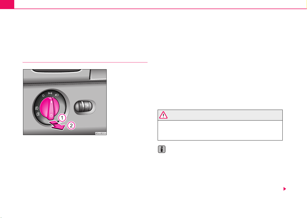
Lights and Visibility56
Lights and Visibility
Lights
Switching lights on and off
Fig. 34 Dash panel:
Light switch
Switching on side lights
– Turn the light switch ⇒ fig. 34 into position
Switching on the low beam and main beam
– Turn the light switch into position .
– Press the main beam lever forward in order to switch on the
main beam ⇒ page 59, fig. 38.
.
Switching off all lights
– Turn the light switch into position O.
Low beam comes on only if the ignition is switched on. The low beam is
switched off automatically when the engine is started and after switching
the ignition off; only the side lights come on.
On models fitted with right-hand steering* the position of the switches
differs from that shown in ⇒ fig. 34. The symbols which mark the switch
positions are identical, however.
In certain countries, the low beam is on a reduced brightness as well as
the side lights, when the ignition is switched on.
WARNING
Never drive with side lights on - risk of accident! The side lights are
not bright enough to light up the road sufficiently in front of you or
to be seen by other oncoming traffic. In this case, always switch on
the low beam when it is dark or if visibilty is poor.
Note
• An audible warning will sound if you withdraw the ignition key and open
the driver's door when the vehicle lights are still on.
• The acoustic warning signal is switched off over the door contact when
the driver's door is closed (ignition off). The vehicle can be parked with the
side lights on.
• If you park the car for a lengthy period, we recommend switching off all
lights, or leaving only the side lights switched on.

Lights and Visibility 57
A
A
• The switching on of the described lights should only be undertaken in
accordance with the legal requirements.
Fog lights
Switching on the fog lights
– First of all turn the light switch ⇒ page 56, fig. 34 into position
or .
– Pull the light switch out to the first detent .
The rear fog light warning light ⇒ page 31 lights up in the instrument
cluster when the fog light is switched off.
The rear fog light
Switching on the rear fog light
– First of all turn the light switch ⇒ page 56, fig. 34 into position
1
or .
– Pull the light switch out to the second detent .
The rear fog light warning light ⇒ page 31 lights up in the instrument
cluster when the fog light is switched off.
Only the rear fog light of the trailer lights up automatically when you are
towing a trailer using a factory-fitted towing device which is fitted with
the rear fog light .
2
Caution
The rear fog light should only be switched on if visibility is particularly poor
(conform with any varying legal provisions) to avoid dazzling vehicles
behind your vehicle.
Instrument lighting
You can adjust the brightness of the instrument lighting.
Fig. 35 Dash panel:
Instrument lighting
– Switch on the light.
– Turn the control dial ⇒ fig. 35 to the desired intensity of the
instrument lighting.
Using the system Safety Driving Tips General Maintenance Breakdown assistance Technical Data

Lights and Visibility58
A
A
A2A
Headlight range adjustment
Once the low beam is switched on you can then adapt the
range of the headlights to the load of the vehicle.
Fig. 36 Dash panel:
Lights and Visibility
– Turn the control dial ⇒ fig. 36 until you have adjusted the
low beam so that oncoming traffic is not dazzled.
Settings
The positions correspond approximately to the following vehicle loads:
-
Front seats occupied, luggage compartment empty.
1
All seats occupied, luggage compartment empty.
All seats occupied, luggage compartment laden.
3
Driver seat occupied, luggage compartment laden.
Caution
Set the headlight beam adjustment in such a way as to avoid dazzling
oncoming traffic.
Note
Headlights fitted with Xenon bulbs adapt automatically to the load and
driving state of the vehicle (e.g. accelerating, braking) when the ignition is
switched on and when driving.
Switch for hazard warning lights
Fig. 37 Dash panel:
Switch for hazard
warning lights
– Press switch ⇒ fig. 37 to switch the hazard warning light
system on or off.
All the turn signal lights on the vehicle flash at the same time when the
hazard warning light system is switched on. The indicator light for the turn
signals and the indicator light in the switch also flash at the same time. You
can also switch on the hazard warning light system if the ignition is
switched off.

Lights and Visibility 59
Please comply with any legal requirements when using the hazard
warning light system.
Note
Switch on the hazard warning light system if, for example:
• you encounter traffic congestion,
• your car breaks down or an emergency situation occurs,
Turn signal and main beam lever
The parking lights and headlight flasher are also switched
on and off using the turn signal and main beam lever.
Fig. 38 Turn signal and
main beam lever
The turn signal and main beam lever perform the following functions:
Right
and left turn signal light
– Push the lever upwards or downwards ⇒ fig. 38.
– Turn signal for changing lanes, in order to only flash briefly -
move the lever up or down to the pressure point and hold it in
this position.
Main beam
– Switch on the low beam.
– Push the lever forwards.
– Pull the lever back into the initial position in order to switch the
main beam off again.
Headlight flasher
– Pull on the lever of the steering wheel (sprung position) - the
main beam and warning light in the instrument cluster come
on.
Parking light
– Switch off the ignition.
– Push the lever up or down - the right-hand or left-hand parking
light is switched on.
Notes on light and indicator functions
• The turn signal system only operates when the ignition is switched
on. The corresponding indicator light or in the instrument cluster also
flashes.
• The turn signal is automatically cancelled after negotiating a curve.
Using the system Safety Driving Tips General Maintenance Breakdown assistance Technical Data

Lights and Visibility60
A
A
• The side light and rear light on the appropriate side of the vehicle are
switched on when the parking light is selected. The parking light function
only operates if the ignition is switched off.
• An acoustic warning signal will sound when the driver's door is opened
if the lever is not in the middle position after removing the ignition key. The
acoustic warning signal will stop just as soon as the driver's door is closed.
Caution
Use main beam or the headlight flasher only if this does not risk dazzling
other road users.
Note
Use only in accordance with the legal requirements the described lighting
and signal systems.
Coming Home Function
This function makes it possible to switch on low or main beam for
a short time after leaving the car, e.g. to illuminate the path to
your front door, etc.
Selecting function
– Switch off the light.
– Switch off the ignition.
If the door remains open, the light remains on for about 3 minutes.
If the door is closed, the light remains on for about 30 seconds.
Interior lighting
Front interior lighting and storage compartment on
front passenger side
Fig. 39 Detail of the
headliner: front interior
lighting
Door contact setting
– Position the switch ⇒ fig. 39 into middle position
A
.
– Flash one time with the headlights.
– Open the door, the low beam lights up.
If you shift the lever into the main beam position, the main beam lights up.
Switching the interior light on
– Press the switch on the symbol
A
.

Lights and Visibility 61
AAA
Switching the interior light off
– Press the switch on the symbol O.
Front reading lights
– Press on one of the switches ⇒ page 60, fig. 39 in order to
B
switch the right or left reading light on or off.
Lighting of storage compartment on the front passenger
side
– Open the flap of the storage compartment on the front
passenger side, the lighting of the storage compartment
switches on automatically and switches off when the flap is
closed.
If the interior lighting is fitted with a delayed-off control*, the lighting of the
interior of the car remains on for a few seconds after the doors are closed.
The interior light comes on as soon as you unlock the car or open a door
or when the ignition key has been removed. The light goes out again
about 30 seconds after all the doors have been closed. The interior
lighting is switched off when you lock the car or switch the ignition on. This
only applies when the switch for the corresponding interior lights is
standing n the door contact setting.
The interior lighting goes off after about 60 minutes when a door has been
left open in order to avoid discharging the battery of the vehicle.
Two LEDs are integrated in the interior lighting, which illuminates the shift
lever and the middle of the dash panel. They are switched on automatically when switching on the parking light.
In addition, the lighting of the door handle is switched on after the ignition
is switched on when the side lights are switched on.
Rear interior lighting
Fig. 40 The roof light
at the rear with interior
monitoring sensors
Fig. 41 The interior
light at the rear without
interior monitoring
sensors
The lights with interior monitoring sensors ⇒ fig. 40 are actuated by
moving the switch to the symbol
, O or to the middle position .
Using the system Safety Driving Tips General Maintenance Breakdown assistance Technical Data

Lights and Visibility62
The lights without interior monitoring sensors ⇒ page 61, fig. 41 are actu-
ated by pressing the glass on the symbol O or by switching to the
middle position .
The functions are the same as for the interior lighting at the front of the car
⇒ page 60.
Luggage compartment light
Fig. 42 Luggage
compartment: Lighting
The light is located at the top side of the luggage compartment.
The lighting ⇒ fig. 42 comes on automatically when the boot lid is opened.
The luggage compartment lighting will switch off again automatically if the
boot lid remains open for more than about 60 minutes.
Entry lighting
The light is located in the door trim panel below.
The light beam is directed towards the entry area of the corresponding
door.
The light switches on when the door is opened and switches off again
when the door is closed.
If the doors remain open, the lighting goes out automatically after about
60 minutes provided the ignition is not switched on.
Visibility
Rear window heater
Fig. 43 Switch for rear
window heater

Lights and Visibility 63
A
A
AAA
– Press switch ⇒ page 62, fig. 43 to switch on the rear window
heater.
The rear window heater operates only if the ignition is switched on. An
indicator light in the switch is illuminated when the rear window heater is
switched on.
The rear window heater switches off automatically after a few minutes.
For the sake of the environment
You should switch off the rear window heater as soon as the rear window
is clear. The reduced current consumption will have a favourable effect on
fuel economy ⇒ page 189.
Sun visors
Using the sun visors can contribute to increasing road
safety.
You can pull the sun visors for the driver and front passenger out of the
fixture and swivel them toward the doors in the direction of the arrow
⇒ fig. 44.
The vanity mirrors in the sun visors are provided with covers. When you
slide open the cover in the direction of the arrow , the vanity mirror
lighting in the headliner switches on automatically. It switches off again
when you slide the cover closed and when you raise the sun visor.
2
1
Sun screen*
Fig. 45 Rear window:
Sun screen
The rear sun screen is located in a housing below the luggage
compartment cover.
Unrolling
– Pull the sun screen at the plate and hang it in the bracket
B
Fig. 44 Sun visor:
swivelling out
Using the system Safety Driving Tips General Maintenance Breakdown assistance Technical Data
⇒ fig. 45.

Lights and Visibility64
A4A
AAA2A
A
A
A
A
Rolling up
– Hold the sun screen in such a way that it can roll up slowly and
without damage into the housing.
The windscreen wiper and washing
system
Windscreen wipers
You can operate the windscreen wipers and automatic
wipe/wash using the windscreen wiper lever.
Fig. 46 Windscreen
wiper lever
The windscreen wiper lever ⇒ fig. 46 has the following positions:
Finger-operated wiping
– Position the lever down into position if you wish to wipe the
windscreen only for a single wipe - spring-tensioned position.
Intermittent wipe
– Position the lever up into position .
– Set with the switch the desired break between the indi-
vidual wiper strokes
Slow wipe
– Position the lever up into position .
Fast wipe
– Position the lever up into position .
Automatic wipe/wash for windscreen
– Pull the lever towards the steering wheel into position and
the widescreen wiper and wash system will operate - in the
sprung position.
– Release the lever. The washer system stops and the wipers
continue operating for a further 4 seconds or so.
Switching windscreen wipers off
– Move the lever back into its home position .
Rain sensor*
– Move the lever into position .
– You can set the sensitivity of the sensor individually with
A
switch .
1
3
5
0
1

Lights and Visibility 65
A0A
A
– If you have switched the ignition off and on again, you must
then once again activate the sensor by moving the lever into
home position , and then back into position .
The windscreen wipers and the windscreen washer system only operate
if the ignition is switched on.
The windscreen washer nozzles are heated* when the ignition is switched
on.
The rain sensor* automatically regulates the break between the individual
wiper strokes depending on the intensity of the rain.
Top up with wash liquid ⇒ page 223.
1
WARNING
• Properly maintained windscreen wiper blades are essential for
clear visibility and safe driving ⇒ page 66, “Replacing windscreen
wiper blades”.
• Do not use the windscreen washer system at low temperatures,
without heating the windscreen beforehand. Otherwise the window
cleaner could freeze on the windscreen and restrict the view to the
front.
Caution
In frosty weather, please first of all check whether the windscreen wiper
blades are not frozen to the windscreen before switching them on.
Switching on windscreen wipers when the blades are frozen to the windscreen may result in damage both to the blades and the motor of the windscreen wipers!
Headlight cleaning system*
Fig. 47 Headlight with
washer nozzle
extended
The headlight lenses are cleaned, when low beam or main beam are
switched on by holding ⇒ page 64 the lever for about 2 seconds in the
position .
The headlight washer nozzles are moved forward out of the bumper by the
water pressure for cleaning the headlights.
You should remove stubborn dirt (such as insect residues) from the headlight lenses at regular intervals, for example when refuelling. Please refer
to the following guidelines ⇒ page 199, “The headlight lenses”.
You should remove any snow from the fixtures of the washer nozzles and
clear ice in winter with a de-icing spray in order to ensure proper operation
of the cleaning system.
5
Using the system Safety Driving Tips General Maintenance Breakdown assistance Technical Data

Lights and Visibility66
Replacing windscreen wiper blades
Fig. 48 Taking off the
wiper blade
Taking off the wiper blade
– Fold windscreen wiper arm away from the windscreen and
position the wiper blade at right angles to the wiper arm.
– Take off the wiper blade in direction of arrow ⇒ fig. 48 ⇒ .
Attaching a wiper blade
– Push the new wiper blade over the wiper arm and turn the
wiper blade into the vertical position.
– Check whether the wiper blade is correctly attached.
Windscreen wiper blades in proper condition are essential to obtain good
visibility. Wiper blades should not be allowed to become dirtied by dust,
insect remains and preserving wax.
Juddering or smearing of the wiper blades could be due to wax residues
left on the windscreen by vehicle washing in automatic vehicle wash
systems. It is therefore important to degrease the lips of the winscreen
wiper blades after every pass through an automatic vehicle wash
system.
WARNING
• If the windscreen wipers are handled carelessly, there is a risk
of damage to the windscreen.
• You should clean the wiper blades regularly with a windscreen
cleaner in order to avoid any smears. Clean a wiper blade with a
sponge or cloth if it is very dirty, for example from insect residues.
• Replace the windscreen wiper blades once or twice a year for
safety reasons. Windscreen wiper blades are available from Škoda
dealers.
Rear-view mirror
Manual dimming interior rear-view mirror
Basic position
– Pull the lever on the bottom edge of the mirror forward.
Dimming mirror
– Pull the lever on the bottom edge of the mirror back.

Lights and Visibility 67
Automatic dimming interior rear-view mirror*
The mirror is dimmed automatically depending on the light striking the
mirror from the rear provided the ignition is switched on. The mirror has no
lever on the bottom edge of the mirror. When the interior lights are
switched on or the reverse gear is engaged, the mirror always moves back
into the basic position (not dimmed).
Note
Automatic mirror dimming operates only properly if the sun screen* for the
rear window is not in use or the light striking the rear of the interior rearview mirror is not affected by other objects.
Exterior mirror with entry lighting*
The lighting is positioned on the bottom edge of the exterior mirror.
The light beam is aimed at the entry area of the front doors after the car is
unlocked.
The light comes on after the doors have been locked or on opening the
front door. The lighting goes out about 30 seconds after the doors are
closed or if the ignition is switched on.
If the doors remain open, the lighting goes out automatically after about
10 minutes provided the ignition is not switched on.
Electrically adjustable rear mirror
Fig. 49 Inner part of
door: rotary knob
(joystick)
The heating of the external mirror functions only when ignition is
switched on.
Heating of the external mirror
– Turn the rotary knob to position
Adjusting left and right exterior mirrors simultaneously
– Turn the rotary knob to position
surface is identical to the movement of the rotary knob.
Adjusting the right-hand exterior mirror
– Turn the rotary knob to position
surface is identical to the movement of the rotary knob.
⇒ fig. 49.
. The movement of the mirror
. The movement of the mirror
Using the system Safety Driving Tips General Maintenance Breakdown assistance Technical Data

Lights and Visibility68
Folding in both exterior mirrors*
– Turn the rotary knob to position
Tilting surface of front passenger exterior mirror*
When the rotary knob is in position ⇒ page 67, fig. 49 and the reverse
gear is engaged, the surface of the mirror tilts down slightly. This provides
an aid in seeing the kerb of the pavement when parking the car.
If you shift out of reverse gear, or switch over to the driver exterior mirror
in position
original position.
Memory for exterior mirrors*
On vehicles fitted with a memory for the driver seat, the relevant setting of
the exterior mirror is also stored automatically when the seat position is
stored ⇒ page 72.
, the mirror surface on the passenger side moves back into the
.
WARNING
• Convex (curved outward) or aspherical exterior mirrors
increase the vision field. They do, however, make objects appear
smaller in the mirror. These mirrors are only of limited use, therefore, for estimating distances to the following vehicles.
• Use whenever possible the interior rear mirror, for estimating
the distances to the following vehicles.
Caution
If the mirror housing has been shifted out of position as a result of external
force (e.g. striking an object when parking), the mirror must then be folded
in fully with the electric motor. On no account attempt to move the mirror
housing back by hand otherwise proper operation of the mirror mechanism will be affected. This applies only to models fitted with the fold-in
function for both exterior mirrors*.
Note
• Do not touch the surface of the exterior mirrors if the exterior mirror
heater is switched on.
• You can set the exterior mirrors by hand, if the power setting function
fails at any time, by pressing on the edge of the mirror surface.
• Contact your Škoda dealer if a fault exists with the power setting of the
exterior mirrors.

Seats and Stowage
Seats and Stowage 69
Front seats
Basic information
The front seats have a wide range of different settings and can thus be
matched to the physical characteristics of the driver and front passenger.
Correct adjustment of the seats is particularly important for
• safely and quickly reaching the controls,
• a relaxed, fatigue-free body position,
• achieving the maximum protection offered by the seat belts and
the airbag system.
The chapters which follow describe the procedure which you should adopt
for adjusting the seats.
WARNING
• Never transport more occupants than the maximum seating in
the vehicle.
• Each occupant must correctly fasten the seat belt belonging to
the seat. Children must be fastened ⇒ page 164, “Transporting
children safely” with a suitable restraint system.
• The front seats and the head restraints must always be adjusted
to match the body size of the seat occupant as well as the seat belts
must always be correctly fastened in order to provide an optimal
protection for you and your occupants.
• Always keep your feet in the footwell when the car is being
driven - never place your feet on the instrument panel, out of the
window or on the surfaces of the seats. This is particularly impor-
WARNING (continued)
tant for the front seat passenger. You will be exposed to increased
risk of injury if it becomes necessary to apply the brake or in the
event of an accident. If an airbag is deployed, you may suffer fatal
injuries when adopting an incorrect seated position!
• It is important for the driver and front passenger to maintain a
distance of at least 25 cm from the steering wheel or dash panel.
Not maintaining this minimum distance will mean that the airbag
system will not be able to properly protect you - hazard! The front
seats and the head restraints must always also be correctly
adjusted to match the body size of the occupant.
• Ensure that there are no objects in the footwell as any objects
may get behind the pedals during a driving or braking manoeuvre.
You would then no longer be able to operate the clutch, to brake or
accelerate.
Using the system Safety Driving Tips General Maintenance Breakdown assistance Technical Data

Seats and Stowage70
A
A1A2A
A3A
Adjusting front seats manually
Fig. 50 Controls at
driver seat
Adjusting a seat in a forward/back direction
– Pull the lever ⇒ fig. 50 up and push the seat into the
desired position.
– Release the lever and push the seat further until the lock
is heard to engage.
Adjusting height of seat
– Lift the seat if required by pulling or pumping lever
⇒ fig. 50 upwards.
– Lower the seat if required by pushing or pumping lever
downwards.
1
2
Adjusting angle of backrest
– Relieve any pressure on the backrest (do not lean on it) and
turn the handwheel to adjust the angle of the backrest.
Adjusting lumbar support
– Turn the handwheel until you have set the most comfort-
4
able curvature of the seat upholstery in the area of your spine.
The driver's seat should be adjusted in such a way that the pedals can be
pressed to the floor with slightly bent legs.
The backrest on the driver's seat should be adjusted in such a way that
the upper point of the steering wheel can be easily reached with slightly
bent arms.
WARNING
• Only adjust the driver seat when the vehicle is stationary - risk
of injury!
• Take care when adjusting the seat! Adjusting the seat without
care can lead to bruises or injuries.
• The backrests must not be angled too far back when driving
otherwise this will affect proper operation of the seat belts and of
the airbag system - risk of injury!

Seats and Stowage 71
AAA
A
AAA
A
Adjusting front seats electrically*
Adjusting seats
Fig. 51 Side view:
controls for adjusting
seat
Adjusting seat
– Adopt the correct seated position ⇒ page 69.
– Press switch or ⇒ fig. 51 in the direction of the desired
setting.
– Turn the handwheel until you have set the most comfort-
able curvature of the seat upholstery in the area of your spine.
Switch is operated in order to move the seat up/down and
forward/back, while switch is operated in order to move the backrest
forward or back.
You can adjust the lumbar support only mechanically with the handwheel
C
.
B
C
B
WARNING
• Only adjust the driver seat when the vehicle is stationary - risk
of injury!
• Caution when adjusting the seat! You may suffer injuries or
bruises as a result of adjusting the seat without paying proper
attention.
• In view of the fact that the seats can also be adjusted when the
ignition is switched off (even when ignition key withdrawn), you
should never leave children unattended in the car.
• The backrests must not be angled too far back when driving
otherwise this will affect proper operation of the seat belts and of
the airbag system - risk of injury!
Note
If the movement of the seat is inadvertently interrupted during an adjustment, once again press the switch in the appropriate direction and
continue with the adjustment of the seat to the end.
Using the system Safety Driving Tips General Maintenance Breakdown assistance Technical Data

Seats and Stowage72
A
ADAEA
ADA
A
A
A
Memory for the seat
Fig. 52 Driver seat:
Memory buttons and
ON/OFF switch
Memory buttons
Memory for the seat offers the possibility to store the individual seat and
external mirror position. An individual position can be allocated to each of
the three memory buttons ⇒ fig. 52, that is three in total. On pressing
the appropriate memory button the seat and external mirror will automatically move into the position allocated to this button.
ON/OFF switch
If you press switch (raised switch), the memory buttons no longer
operate. You can now adjust the seat electrically without using the
memory buttons . After pressing switch once again, the seat can be
reset with the memory buttons. If you had already started an operation to
retrieve the settings, this operation is not continued.
If the car is used only by one driver, it is not necessary to store particular
settings in this case, we recommend that you press the button (raised
button).
D
D
E
E
Emergency Off
If you operate any button or the switch ON/OFF of the driver seat, you can
interrupt the setting operation at any time in an emergency.
Storing and retrieving settings
Storing seat and exterior mirror settings for driving forward
– Switch on the ignition.
– Adjust the seat ⇒ page 71.
– Adjust both exterior mirrors ⇒ page 67.
– Press one of the memory buttons and hold the button
pressed for about 3 seconds until an audible signal confirms
that the setting has been stored.
Storing exterior mirror setting for reversing
– Switch on the ignition.
– Turn the exterior mirror control to position
fig. 49.
– Engage reverse gear.
– Move the right exterior mirror into the desired position
⇒ page 67.
– Press one of the memory buttons and hold the button
pressed for about 3 seconds until an audible signal confirms
that the exterior mirror setting for reversing has been stored.
D
⇒ page 67,
D

Seats and Stowage 73
A
Note
• When storing settings with the memory buttons, we recommend that
you begin with the front button and assign a memory button to each additional driver.
• Each new setting stored with the same button erases the previous
setting.
• Each time you store the seat and exterior mirror settings for driving
forward you also have to re-store the individual setting of the exterior
mirror on the passenger side for reversing.
Assigning remote control to the memory buttons
After storing the settings of the seat and exterior mirrors, you
have 10 seconds in order to assign the remote control to the
appropriate memory button.
– Withdraw the ignition key.
– Press the release button ⇒ page 47 and hold it pressed for 1
second until an audible signal confirms that the setting has
been stored. The setting is stored with the memory button
which you have selected.
If you wish to be able to retrieve the settings which are stored in the
memory by also using the remote control, you have to assign the remote
control to a memory button in each case.
We recommend that you assign one of the two remote controls supplied
with your car, to the front memory button, and the other remote control key
to the middle memory button.
If you wish, you can obtain an additional key with radio remote control from
a Škoda dealer and then assign the radio remote control to the rear
memory button.
Note
• If the remote control had previously been assigned to another memory
button, this setting is then erased by the new assignment.
• If you assign the remote control to a memory button which has already
been assigned to a remote control, the old assignment is also replaced by
a new assignment in this case.
• The assignment of the remote control to a memory button is retained,
however, after reassigning the seats and exterior mirrors.
Retrieving seat and exterior mirror settings for driving
forward
You can retrieve the stored settings either with the
memory buttons or with the remote control*.
Retrieving settings with memory buttons
– For safety reasons, you can only retrieve the seat and mirror
settings if the ignition is switched off. You have a choice of two
different ways of retrieving the settings:
– One-touch automatic memory: with the driver door open,
operate the desired memory button ⇒ page 72, fig. 52
with one-touch. The seat and the exterior mirrors now move
automatically into the stored position.
D
Using the system Safety Driving Tips General Maintenance Breakdown assistance Technical Data

Seats and Stowage74
A
A
– Memory keying: with the driver door open or closed, press
and hold the desired memory button until the seat and the
D
exterior mirrors have moved into the stored position.
Retrieving settings with remote control
– If the driver door is closed and the ignition is switched off,
briefly press the unlock button of the remote control
⇒ page 47 and then open the door.
– The seat and exterior mirrors now move automatically into the
stored positions.
Retrieving setting of exterior mirror for reversing*
– Turn the rotary knob for the exterior mirror setting into the
position
Emergency Off
You can interrupt any memory retrieval operation in an emergency by
pressing the switch ⇒ page 72, fig. 52, by one-touch of a memory
button or by pressing the seat setting switch.
⇒ page 67 before engaging the reverse gear.
E
Head restraints
Fig. 53 Adjusting head
restraint
Fig. 54 Removing a
head restraint

Seats and Stowage 75
AAA
Adjusting the height of a head restraint
– Grasp the side of the head restraint with both hands and push
it up or down in direction of arrow ⇒ page 74, fig. 53. Best
protection is achieved if the top edge of the head restraint is at
the same level as the upper part of your head ⇒ page 141,
fig. 123.
Adjusting the angle of a head restraint
– The head restraint can be matched to the head of the occu-
pant by adjusting the angle in the direction of the arrow .
B
Adjusting the angle of the head restraint provides enhanced
comfort for the user.
Removing and installing a head restraint
– Pull the head restraint out of the backrest of the seat as far as
the stop.
– Press the locking button in the direction of arrow ⇒ page 74,
fig. 54 and pull the head restraint out.
– To re-insert the head restraint, push it down into the backrest
of the seat far enough until you hear the locking button
engage.
The head restraints of the front seats can be adjusted for angle and height
⇒ page 74, fig. 53, the outer head restraints at the rear can be adjusted
for height (about 15 mm). The middle rear head restraint is fixed.
The head restraints must be adjusted to match the size of the seat occupant. Correctly adjusted head restraints together with the seat belts offer
effective protection for the occupants.
WARNING
• The head restraints must be correctly adjusted in order to offer
effective protection for the occupants in the event of an accident.
• Do not drive under any circumstance with removed head
restraints - risk of injury!
Using the system Safety Driving Tips General Maintenance Breakdown assistance Technical Data

Seats and Stowage76
A
A
A
A
Front passenger seat with a folding
central back rest*
Folding out and setting
Fig. 55 Front
passenger seat: folding
central back rest
You can fold out the central back rest of the front passenger seat
during a long journey for improved comfort. It then serves as a
comfortable footrest for the occupants in the rear. You can adjust
the position of the footrest by adjusting the passenger seat using
the switches in the armrest of the rear seats ⇒ fig. 56.
Folding out the central back rest
– Pull the handle in direction of arrow ⇒ fig. 55 and pull the
central part of the back rest downwards.
Folding up the central back rest
– Fold the central back rest up until it is heard to lock.
Adjusting the passenger seat
– Tilt the back rest forwards or backwards using switch .
– Move the front part of the seat upwards or downwards using
B
switch .
– Shift the seat forwards or backwards using switch .
– Move the rear part of the seat upwards or downwards using
D
switch .
Caution
A
C
• The maximum loading of the foldable central part of the seat is 30 kilo-
grams.
• Never use the foldable central part of the seat as an additional seat.
Fig. 56 Armrest of rear
seats: Operating the
passenger seat

Seats and Stowage 77
A
ABA
Note
You can use a protective sack ⇒ page 77 in order to prevent any dirt
getting onto the passenger seat.
Protective sack*
When using the foldable central part of the back rest the
protective sack reduces dirt getting on the passenger seat.
Fig. 57 Front
passenger seat:
Protective sack
The protective sack is stored in the storage compartment in the
back rest of the driver's seat.
Installing the protective sack
– Lay the unfolded protective sack on the passenger seat.
– Pull the belt through the opening in the passenger seat and
A
pull it over the head restraint ⇒ fig. 57.
– Pull the belt under the folded down support and secure it
with head .
C
– The protective sack is folded up in the reverse order.
The protective sack has zip on the upper side to release air. It allows the
upper side to be opened out.
You can also use the protective sack as a luggage bag.
Footrest at the rear*
Fig. 58 The floor
behind the front seat:
Footrest at the rear
– Fold out the central part of the back rest ⇒ page 76.
Using the system Safety Driving Tips General Maintenance Breakdown assistance Technical Data

Seats and Stowage78
A1A2AAA
The occupants sitting in the rear of the car can use ⇒ page 77,
fig. 58 the foot rest for increased comfort. The foot rest is
attached to the carpet by a velcro fastener.
Seat heaters*
Fig. 59 Dash panel:
Control dial for heating
the front seats
Fig. 60 Centre console
at rear: Rotary controls
for heaters of rear seats
You can heat the surfaces of the seats and of the backrests of the
front seats and the two outer rear seats.
Front seats
– You can switch on and adjust the heaters of the driver and
front passenger seats by turning the rotary controls and
⇒ fig. 59, respectively.
Rear seats
– You can switch on and adjust the heaters of the left and right
rear seats by turning the rotary controls and ⇒ fig. 60,
B
respectively.
If the rotary controls are in the 0 position, the seat heater is switched off.
When the seat heater is switched on, the numerical marking of the rotary
control is illuminated. The control range extends from 1 to 5.

Seats and Stowage 79
Caution
• You should not kneel on the seats or otherwise apply pressure at
specific points in order to avoid damaging the heating elements of the seat
heaters.
• Do not clean the seats moist ⇒ page 201.
Note
The seat heating should only be switched on when the engine is running.
This has a significant effect of saving on the battery capacity.
Pedals
You should use only footmats which do not obstruct the movement of the
pedals and have an anti-slip protection.
Operation of the pedals must not be hindered!
WARNING
• Greater pedal distances may be needed when there is a fault in
the brake system.
• Do not place any footmats or other additional floor coverings in
the area of the pedals in order to ensure that all the pedals can be
fully depressed and are able to return unobstructed to their initial
position - risk of accident!
• There must be no objects on the floor which could roll under the
pedals. You would then no longer be able to apply the brakes,
operate the clutch or accelerator - risk of accident!
Luggage compartment
Loading the luggage compartment
Please observe the following in the interest of having good
handling characteristics of your vehicle:
– Distribute the items of luggage as evenly as possible.
– Place heavy objects as far forward as possible.
– Attach the items of luggage with the safety net* or with
tensioning straps attached to the lashing eyes ⇒ page 80.
In the event of an accident, there is such a high kinetic energy which is
produced by small and light objects that they can cause severe injuries.
The magnitude of the kinetic energy depends on the speed at which the
vehicle is travelling and on the weight of the object. The speed at which
the vehicle is travelling is in this case the more significant factor.
Example: In the event of a frontal collision at a speed of 50 km/h, an unsecured object with a weight of 4.5 kg produces an energy, which corresponds to 20 times its own weight. This means that it results in a weight
of approx. 90 kg. You can imagine the injuries that can occur, if this “bullet”
is flying through the interior compartment and hits an occupant.
WARNING
• Store the objects in the luggage compartment and attach them
to the lashing eyes.
• Loose objects in the passenger compartment can be thrown
forward during a sudden manoeuvre or in case of an accident and
can injure the occupants or other oncoming traffic. This risk is still
increased, if the objects which are flying around are hit by a
Using the system Safety Driving Tips General Maintenance Breakdown assistance Technical Data

Seats and Stowage80
WARNING (continued)
deployed airbag. In this case, the objects which are thrown back
can injure the occupants - hazard!
• Please note that the handling properties of your vehicle may be
affected when transporting heavy objects as a result of the
displacement of the centre of gravity. The speed and style of
driving must be adjusted accordingly.
• The items carried in the luggage compartment should be stored
in such a way that no objects are able to slip forward if there are any
sudden driving or braking manoeuvres undertaken - risk of injury!
• Never drive with the boot lid slightly ajar or even fully opened
otherwise exhaust gases may get into the interior of the vehicle risk of poisoning!
• On no account exceed the permissible axle loads and the
permissible gross weight of the vehicle - risk of accident!
• Never transport occupants in the luggage compartment!
Note
• Tyre pressure must be adjusted to the load ⇒ page 226, fig. 169.
• The air circulation in the interior of the car helps to prevent the
windows from misting up. Stale air is diverted via the outlet nozzles into
the lateral trim panels of the luggage compartment. Check for yourself that
the outlet nozzles are not covered.
• On vehicles fitted without foldable backrest but with fixed backrest, the
luggage compartment cannot be enlarged.
Lashing eyes
Fig. 61 Position of
lashing eyes in luggage
compartment
Eyes are located on the sides of the loading area for lashing the goods to
be loaded ⇒ fig. 61.
You can also attach a securing net* to these eyes for lashing small objects.
The securing net* and the fixing instruction is located in the well under the
floor covering of the lugagge compartment behind the spare wheel.
WARNING
• The load to be transported must be fixed in place in such a way
that it cannot move during the journey and when braking.
• If the items of luggage or objects are attached to the lashing
eyes with unsuitable or damaged lashing straps, injuries can occur
in the event of braking manoeuvres or accidents. In order to
prevent the items of luggage being thrown forward, always use

Seats and Stowage 81
WARNING (continued)
suitable lashing straps which are firmly attached to the lashing
eyes. Never attach a child seat to the lashing eyes!
Folding double hooks
Fig. 62 Folding double
hooks
Folding double hooks for attaching small items of luggage, such as bags
etc., are provided on both sides of the luggage compartment ⇒ fig. 62.
An item of luggage weighing up to 5 kg can be attached to each side of
the double hook.
Side compartment
Fig. 63 Luggage
compartment: Side
compartment
– You can open the compartment by turning the locks in the
direction of arrow ⇒ fig. 63.
The CD changer* and the first-aid box* ⇒ page 235 is housed in this
compartment.
Using the system Safety Driving Tips General Maintenance Breakdown assistance Technical Data

Seats and Stowage82
AAA
A
Folding down the backrest of the rear seats*
Fig. 64 Unlock the seat
backrest
Fig. 65 Blocking the
unlock knob
The luggage compartment can be enlarged if necessary by
folding one or both seat backrests forward.
Folding the seat backrest forwards
– Before folding the seat backrest forwards, the front seats must
be adjusted so that the front seats are not damaged when
folding the seat backrest forwards.
– Pull the unlocking knob ⇒ fig. 64 and fold the rear seat
backrest forwards completely.
Fold the seat backrest back into position
– Place the rear lateral seat belt behind the edge of the side
B
trim panel.
– Then push the seat backrest back into the upright position
until it clicks into place - check by pulling on it.
– Ensure that the red surface on the front side of the knob is
A
not visible.
Blocking the unlock knobs
– Fold the seat backrest back into position and ensure that it is
correctly interlocked.
– The unlock knobs are blocked by turning the slit in the lock to
the right ⇒ fig. 65 with the master key.
Unblock the unlock knobs
– The unlock knobs are unblocked by turning the slit in the lock
to the left ⇒ fig. 65 with the master key.
The blocking of the seat backrest is equipped with a warning function.
When the seat backrest is unlocked, the red surface on the knob is visible.
If the seat backrest is correctly locked, the knob is pushed back and the
red surface is not visible.

Seats and Stowage 83
WARNING
• The belt locks and the pelvic belt must be in their original posi-
tion after folding back the seat backrest - they must be ready to use.
• The seat backrests must be securely interlocked in position so
that no objects in the luggage compartment can slide forward if
there is sudden braking - risk of injury!
• Pay attention that the rear seat backrest is correctly interlocked.
It is only then that the three-point seat belt for the middle seat can
reliably fulfil its function.
• Before folding the seat backrest back into the secure position,
place the rear lateral seat belt behind the edge of the side trim
panel. Take suitable measures to prevent that the seat belt is
jammed between the side trim panel and the seat backrest and is
thus damaged.
The luggage compartment cover
You can use the luggage compartment cover behind the head restraints
of the rear seats for storing light and soft items.
WARNING
No objects should be placed on the luggage compartment cover,
the vehicle occupants could be endangered if there is sudden
braking or the vehicle collides with something.
Through-loading bag*
The through-loading bag enables you to conveniently
transport long objects (such as skis) without damaging the
interior of the car.
Fig. 66 Luggage
compartment: cover for
through-loading bag
Caution
Please ensure that the heating elements of the rear window heater are not
damaged as a result of objects placed in this area.
Using the system Safety Driving Tips General Maintenance Breakdown assistance Technical Data
Fig. 67 Attaching
through-loading bag to
middle seat belt buckle
of rear seats

Seats and Stowage84
AAA
A
A
Loading
– Fold down the armrest of the rear seats to the front.
– Press the unlock button for the cover of the through-loading
bag in the interior of the car and swivel it down.
– Pull the bag out and unfold it.
– Open the boot lid/luggage compartment door.
– Press the unlock button for the cover of the through-loading
bag ⇒ page 83, fig. 66 and swivel it down.
– Push the objects into the through-loading bag from the boot
⇒ .
Securing
– Insert the belt ⇒ page 83, fig. 67 into the middle seat belt
buckle .
– Pull the seat belt tight in direction of arrow ⇒ page 83,
B
C
fig. 67.
Stowing
– Close the cover for the through-loading bag in the boot.
– Carefully fold the through-loading bag together (approx. 11 cm
packet).
– Close the cover in the interior of the car.
WARNING
After placing items into the through-loading bag, you must secure
the bag with the belt .
A
Note
Never fold the though-loading bag together if it is moist.
The cool box in the armrest of rear seats*
Using the system
Fig. 68 Cool box
– Move the armrest back into its original position.
The contents of the cool box is cooled to a temperature of about
20 °C below the ambient temperature, but to a maximum of
approx.+ 5 °C.

Seats and Stowage 85
A
Opening and Closing
– Pull the handle ⇒ page 84, fig. 68 and pull the lid downwards.
– Open up the lid of the cool box upwards until it is heard to lock.
Switching on and off
– The cooling action of the cool box is switched on and off using
A
switch ⇒ page 84, fig. 68. It is signalised by the lighting up
of the indicator light on the switch.
You can remove the cool box if necessary ⇒ page 86. You can replace the
cool box with a storage net ⇒ fig. 69.
Caution
Never cover the ventilator on the cool box otherwise it will overheat and
could be damaged.
Note
The cool box also operates if the ignition is switched off. The battery will
not run down fully, however, since the system is fitted with a device which
monitors the battery charge level. The cool box will be automatically
switched off when it is threatening to empty the battery.
Partition with storage net
Fig. 69 Partition with
storage net
If the cool box is removed, install the partition with the storage net
⇒ fig. 69 which is fixed with a velcro fastener to the side wall of
the cool box.
– The partition is installed and removed in a similar way to the
cool box ⇒ page 86.
Using the system Safety Driving Tips General Maintenance Breakdown assistance Technical Data

Seats and Stowage86
AAA
A2A
A
A2A
A
Removing and installing the cool box
Fig. 70 Removing the
cool box
Fig. 71 Installing the
cool box
Removing
– Switch the cooling mode of the cool box off ⇒ page 84.
– Remove the locking mechanism ⇒ fig. 70.
– Open the lid of the cool box.
– Press open the upper side of the cool box from the inside in
the direction of arrow and put away the cool box in the
1
luggage compartment (see arrow ).
– Unplug the plug connector (the plug connector is located in
the luggage compartment in the lower part of the fixing frame
for the cool box).
Installing
– Place the cool box on the luggage compartment partition and
plug in the plug.
– Remove the locking mechanism ⇒ fig. 70.
A
– Fold the lid of the cool box onto the fixing frame ⇒ fig. 71.
– Lift the cool box with the palm of the hand on the inside of the
upper wall of the cool box.
– Insert the cool box with the lower edge into the lower holding
bracket on the luggage compartment partition.
– Pull the cool box forwards to the upper edge until the stop (see
1
arrow ), press with the palm of the hand onto the upper wall
(see arrow ), pull the box again forwards and press downwards (see arrow ).
– Push the locking mechanism ⇒ fig. 70 up to the stop into
3
A
the fixing frame.
– Close the lid of the cool box.

Seats and Stowage 87
CargoFlex folding box*
Lowering and securing folding box
Fig. 72 Folding box:
Transport position
You can transport the folding box in two different positions - in the
transport position against the partition ⇒ fig. 72 of the luggage
compartment, or in the ready position lowered onto the floor of
the luggage compartment ⇒ fig. 73.
Lowering folding box into the ready position
– Pull the snap handle in direction of arrow 1 ⇒ fig. 72. The
folding box is lowered to just above the floor of the luggage
compartment.
– Press the folding box at the arrow positions 2 ⇒ fig. 73 onto
the floor of the luggage compartment until it locks in place. If
correctly locked, the snap handle moves back into its initial
position (the top red surface of the handle is not visible).
Securing folding box in the transport position against
partition of luggage compartment
– Lower the folding box into the ready position ⇒ page 89.
– Pull the snap handle in direction of arrow 1 ⇒ fig. 72. The
folding box is raised up from the luggage compartment floor.
– Raise and press the folding box against the partition of the
luggage compartment, it is secured audibly in this way in the
transport position. If correctly locked, the snap handle moves
back into its initial position (the top red surface of the handle
is not visible).
Opening folding box ⇒ page 88.
Fig. 73 Folding box:
ready position
Using the system Safety Driving Tips General Maintenance Breakdown assistance Technical Data

Seats and Stowage88
A
AAA
Caution
The parts of the folding box can be damaged if handled roughly or in an
unprofessional way.
Opening folding box
Fig. 74 Luggage
compartment: folding
box
Fig. 75 Opening
folding box
You can transport the opened folding box in the secured end or
middle position against the partition of the luggage compartment.
Opening folding box
– Lower the folding box into the ready position ⇒ page 87.
– Press the button marked “PUSH” ⇒ fig. 74.
B
– Grasp the folding box at the handle and push it in direction
of arrow 1 against the partition of the luggage compartment
into the secured position. The lock below the button must be
heard to engage. If correctly locked, the button marked
“PUSH” moves back into its initial position.
B
– Raise the lid in direction of arrow 2 ⇒ fig. 75.

Seats and Stowage 89
ACADA
A
– Press on the bottom part of the handle and open the
compartments in the direction of arrow 3. The compartment
wall must be heard to engage in the slot in the bottom part of
the box.
Moving folding box into secured middle position
– Press on the button marked “PUSH” ⇒ page 88, fig. 75
and carefully push the folding box into the secured middle
position. If correctly locked, the button marked “PUSH” is
D
moved back into its initial position. You can now use the space
which has become available for stowing further items of
luggage.
Caution
• The parts of the folding box can be damaged if handled roughly or in
an unprofessional way.
• The maximum weight of goods to be loaded should not exceed 25
kg.
Lowering folding box
Fig. 76 Lowering
folding box
Fig. 77 Securing
folding box
– Press the bottom part of the handle ⇒ fig. 76 and fold the
A
compartments in direction of arrow 1. The compartments must
be heard to engage in the lid.
Using the system Safety Driving Tips General Maintenance Breakdown assistance Technical Data

Seats and Stowage90
A
A
A3A
– Close the lid in direction of arrow 2.
– Press on the button marked “PUSH” ⇒ page 89, fig. 77
B
and push the folding box into the secured middle position.
– Once again press on the button marked “PUSH” and push
B
the folding box carefully into the secured position against the
partition of the luggage compartment in direction of arrow
(ready position). If correctly locked, the button marked “PUSH”
B
is moved back into its initial position.
You can leave the folding box in the ready position for use, or lower it into
the transport position ⇒ page 87.
Caution
• The parts of the folding box can be damaged if handled roughly or in
an unprofessional way.
• First check for yourself whether the cover for the through-loading bag*
is closed before you lower the folding box into the ready position on the
partition of the luggage compartment ⇒ page 83.
The roof luggage rack system
Description
Pay attention to the following points if you wish to transport luggage or
other items on the roof of your vehicle:
• Your car has streamlined rain channels integrated into the roof. For
this reason, it is not possible to use conventional roof racks. We therefore
recommend that you only use base roof bars from the Škoda Genuine
Accessories.
• These base roof bars are the supporting elements for a complete roof
bar system. Separate additional components are required for safety
reasons for transporting luggage, bikes, surfboards, skis and boats. All
these system components are available from Škoda Dealers.
Caution
• If you use other roof rack systems or if the roof bars are not properly
fitted, then any damage which may result to your car is not covered by the
warranty agreements. It is therefore essential to pay attention to the fitting
instructions supplied with the roof luggage rack system.
• On models fitted with a power sliding/tilting roof, ensure that the
opened sliding/tilting roof does not strike any items of luggage transported
on the roof.
For the sake of the environment
The increased aerodynamic drag results in a higher fuel consumption.
One should therefore take off the roof bar system after use.

Seats and Stowage 91
Attachment points
Fig. 78 Attachment
points for roof bars
Installing
When fitting on the feet of the roof bars, ensure that they are positioned
exactly between the arrow markings in the sealing strip on the roof
⇒ fig. 78. The markings are visible only when the doors are open.
Roof load
Distribute weight evenly over the roof luggage rack system. The maximum
permissible roof load (including roof rack system) of 100 kg and the
maximum permissible total weight of the vehicle should not be exceeded.
You cannot make full use of the permissible roof load if you use a roof
luggage rack system with a lower load carrying capacity. The load transported on the roof luggage rack system must not exceed the weight limit
which is stated in the fitting instructions.
WARNING
• The items which you transport on the roof bar system must be
reliably attached - risk of accident!
• You must on no account exceed the permissible roof load, the
permissible axle loads and the permissible gross weight of your
vehicle - risk of accident!
• Please note that the handling properties of your vehicle change
when you transport heavy or bulky items on the roof bar system as
a result of the displacement of the centre of gravity and the
increased wind attack area - risk of accident! You must absolutely
adapt your style of driving and the speed of the vehicle to the
specific circumstances.
Using the system Safety Driving Tips General Maintenance Breakdown assistance Technical Data

Seats and Stowage92
Drinks can holder
Drinks can holder in centre console
Fig. 79 Centre
console: Drinks can
holder
You can place two cups or beverage cans into the recesses ⇒ fig. 79.
WARNING
• Do not place any hot beverages into the can holder while the car
is moving. The hot beverages may spill - risk of scalding!
• Do not use any cups or beakers which are made of hard or brittle
material (e.g. glass, porcelain). You might be injured by them in the
event of an accident!
Drinks can holder in armrest of the rear seats
Fig. 80 Drinks can
holder in rear armrest
The drinks can holder is provided in the stowage compartment.
Access to drinks can holder
– Raise the cover of the armrest.
– You can take off the drinks can holder. Unlock it ⇒ fig. 80 and
attach it to the cover of the armrest.
Only place cans into the drinks can holder which are held tight in the
holder.
It is possible to place up to two beverage cans in the drinks can holder of
the armrest.

Seats and Stowage 93
AAA
WARNING
• Do not place any hot beverages into the can holder while the car
is moving. The hot beverages may spill - risk of scalding!
• Do not use any cups or beakers which are made of hard or brittle
material (e.g. glass, porcelain). You might be injured by them in the
event of an accident!
Ashtray
Ashtray at the front
Fig. 81 Centre
console: opened
ashtray
Opening ashtray
– Press on the bottom part of the cover of the ashtray - refer to
⇒ fig. 81.
Removing the ashtray insert
– Grasp the ashtray insert ⇒ fig. 81 at the side recesses and
B
pull it out.
Replacing the ashtray insert
– Press the ashtray insert into the mount.
WARNING
Never lay flammable objects in the ashtray basin - risk of fire!
Ashtray at the rear*
Fig. 82 Ashtray at the
rear
Opening ashtray
– Press on the top part of the cover of the ashtray.
Using the system Safety Driving Tips General Maintenance Breakdown assistance Technical Data

Seats and Stowage94
AAA
Removing the ashtray insert
– Press the cover of the ashtray down slightly as far as the stop.
– Grasp the ashtray insert and pull it out at an angle of about
45°.
Replacing the ashtray insert
– Position the ashtray insert at an angle of about 45° and press
it into the mount as far the stop.
WARNING
Never lay flammable objects in the ashtray basin - risk of fire!
Ashtray in the armrest*
Ashtray located in the armrest of the rear right door
Opening ashtray
– Press on the middle part of the cover of the ashtray.
Removing the ashtray insert
– Press on the top part of the opened ashtray in position , the
ashtray insert is raised ⇒ fig. 83.
B
Replacing the ashtray insert
– Press the ashtray insert into the armrest.
WARNING
Never lay flammable objects in the ashtray basin - risk of fire!
Fig. 83 Ashtray in the
armrest of the rear right
door

Seats and Stowage 95
A
Cigarette lighters and power sockets
Cigarette lighter
You can also use the socket on the cigarette lighter for
other electrical appliances.
Fig. 84 Centre
console: Cigarette
lighter
Using the cigarette lighter
– Press on the bottom part of the cover of the ashtray - refer to
A
⇒ fig. 84.
– Press in the button of the cigarette lighter (see arrow).
– Wait until the button jumps forward.
Using the power socket
– Take out the cigarette lighter.
– Insert the plug of the electrical appliance into the socket of the
cigarette lighter.
The 12 volt power socket can also be used to supply power to electrical
accessories with a power uptake up to 100 watts.
WARNING
• Take care when using the cigarette lighter! Not paying proper
attention or incorrect use the cigarette lighter in an uncontrolled
manner may result in burns.
• The cigarette lighter and the power socket also operates when
the ignition is switched off or the ignition key withdrawn. This is
why you should never leave children unattended in the vehicle!
Caution
Only use matching plugs, which fulfils the DIN - ISO Standard 4165, to
avoid damaging the power sockets.
Note
Connecting electrical components when the engine is not running
will drain the battery of the vehicle - risk of battery draining!
– Remove the cigarette lighter immediately and use it.
– Insert the cigarette lighter again into the socket.
Using the system Safety Driving Tips General Maintenance Breakdown assistance Technical Data

Seats and Stowage96
Cigarette lighter in rear compartment*
Fig. 85 Centre
console: Cigarette
lighter
Operating and further information regarding the use of the cigarette lighter
⇒ page 95.
Power socket in the luggage compartment
Fig. 86 Luggage
compartment: Power
socket
– Open the cover of the power socket ⇒ fig. 86.
– Connect the plug of the electrical appliance to the socket.
It fulfils the requirements of DIN standard ISO 4165 and must only be used
for connecting approved electrical accessories with a power uptake of up
to 100 watts. The vehicle battery will be discharged in the process if the
engine is stationary.
Further information concerning use of the power socket ⇒ page 233,
“Accessories and replacement parts”.

Seats and Stowage 97
Storage facilities
An overview
You will find the following storage facilities in your vehicle:
First-aid box ⇒ page 235
Stowage compartment for warning triangle ⇒ page 235
Storage compartment on the front passenger
side
Storage drawer* ⇒ page 98
Stowage compartment in centre console ⇒ page 99
Stowage compartment for spectacles* ⇒ page 99
Stowage compartment below steering wheel ⇒ page 100
Stowage compartment in door panel ⇒ page 100
Stowage compartment for an umbrella* ⇒ page 101
Armrest with stowage compartment ⇒ page 102
Rear armrest with stowage compartment* ⇒ page 103
Clothes hooks ⇒ page 103
WARNING
• Please do not place anything on top of the dash panel. Such
objects might slide or fall down when driving (when accelerating or
cornering) and may distract you from concentrating on the traffic
situation - risk of accident!
• Ensure that when driving no objects from the centre console of
from other storage possibilities may get into the footwell of the
⇒ page 97
WARNING (continued)
driver. You would then no longer be able to apply the brakes,
operate the clutch or accelerator - risk of accident!
Storage compartment on the front passenger side
The storage compartment on the front passenger side is
lockable* and illuminated.
Fig. 87 Dash panel:
Storage compartment
Opening the storage compartment
– Pull the handle in the lid in direction of arrow ⇒ fig. 87 and pull
the lid down.
Closing the storage compartment
– Raise the lid and press it until the catch is heard to engage.
Using the system Safety Driving Tips General Maintenance Breakdown assistance Technical Data

Seats and Stowage98
Locking the storage compartment
– Turn the master key in the lock to the right.
Unlocking the storage compartment
– Turn the master key in the lock to the left.
Two holders for placing drink cans are located on the inside of the lid.
WARNING
• The storage compartment must always be closed when driving
for safety reasons!
• The drinks can holder should not be used while driving.
Cooling of storage compartment on front passenger
side
– You can switch the cooling system on or off using the control
dial ⇒ fig. 88.
The cooling of the storage compartment operates only if the air conditioning system is switched on. We recommend that you switch off the
cooling (opening concealed) if it is operating in the heating mode or if you
are not using the cooling system for the storage compartment.
Storage drawer*
Fig. 89 Dash panel:
Storage drawer
– Press in the middle of the storage compartment ⇒ fig. 89 and
the storage compartment will come out.
Fig. 88 Storage
compartment: Control
dial for the cooling
system
WARNING
• The storage compartment is not a substitute for the ashtray and
must also not be used for such purposes - risk of fire!

Seats and Stowage 99
WARNING (continued)
• The storage compartment must always be closed when driving
for safety reasons!
Stowage compartment in centre console
Fig. 90 Centre
console: Storage
compartment
Opening
– Press on the top part of the cover in direction of arrow. The
drawer will come out.
Pulling out compartment
– Press the compartment in the opening direction as far as the
stop. Grasp the compartment at the sides and pull it up and
out.
Inserting compartment
– Insert the compartment back into its mount and close the
cover.
WARNING
• The storage compartment is not a substitute for the ashtray and
must also not be used for such purposes - risk of fire!
• The storage compartment must always be closed when driving
for safety reasons.
Stowage compartment for spectacles*
Fig. 91 Stowage
compartment for spectacles
The stowage compartment is located above the front left window.
Using the system Safety Driving Tips General Maintenance Breakdown assistance Technical Data
 Loading...