

SIMPLY CLEVER
ŠkodaSuperb
SUPPLEMENT TO THE OWNER'S MANUAL
Technical Changes 12/2009
Introduction 1
Introduction
This supplement replaces the Owner's manual SUPERB Edition 05.09 (referred to in the
following simply as the Owner's manual).
The information given in this supplement takes preference over the information
contained in the Owner's manual.
Special accessories are marked with a *.
We wish you a good journey at all times
Škoda Auto a.s.
Multi-functional indicator (onboard
computer)*
The multi-functional indicator (depending on the equipment) provides the following
information:
• oil temperature
Note
If the oil temperature is lower than 50°C or if a fault in the system for checking the oil
temperature is present, three lines are displayed instead of the oil temperature.
Information display* (Combi)
Setup
In the menu Setup, you can select (depending on equipment fitted) the following
menu points:
• Autom. blind
Automatic blind (Combi)
Here you can deactivate/activate the automatic roll-up function of the luggage
compartment roll cover when opening the boot lid.
Red symbols
Meaning of the red symbols:
Overheated clutches of the automatic gearbox DSG*
⇒ page 1
Temperature of the clutches of the automatic
gearbox DSG*
In the event that the temperature of the clutches of the automatic gearbox DSG is too
high, the symbol and the warning are shown in the information display*.
Gearbox overheated: Stop! Owner's man.!
An audible signal sounds as an additional warning signal.
WARNING
If you must stop for technical reasons, then park the vehicle at a safe distance
from the traffic and switch off the engine and switch on the hazard warning light
system.
Caution
In the event that the clutches of the automatic gearbox have overheated, bring the
vehicle to a stop and switch off the engine. You must wait until the symbol and the
warning go out - risk of gearbox damage! You can continue the trip as soon as the
symbol and the warning go out.
Electronic stability programme (ESP)* 2
A
AAA1A
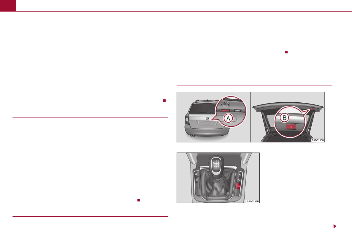
Electronic stability programme (ESP)*
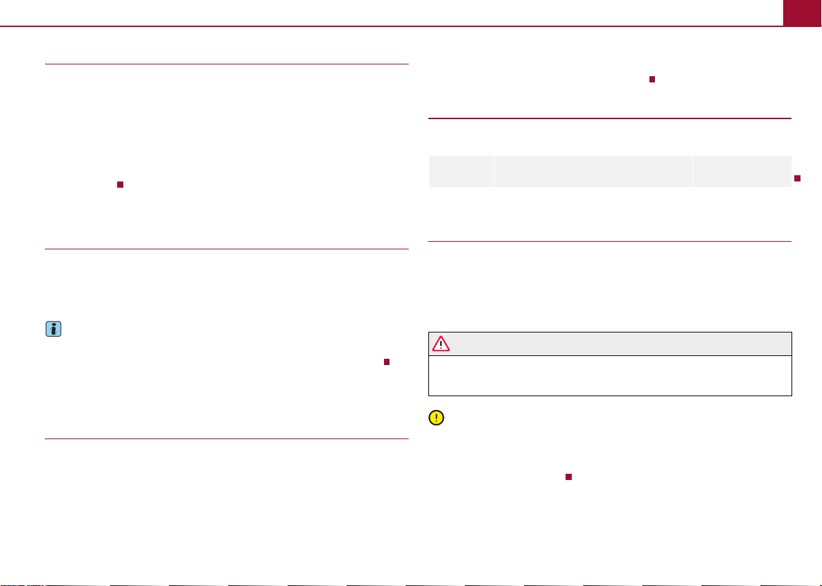
Fig. 3 Remote control key
Fig. 1 ESP button
When the ESP system helps to stabilise the vehi cle, the warning light flashes quickly.
The ESP system cannot be switched off, only the TCS system can be switched off by
pressing the button ⇒ fig. 1, the indicator light then flashes slowly.
The warning light lights up permanently if there is a fault in the ESP system.
If the warning light comes on immediately after star ting the engine, the ESP system
can be switched off for technical reasons. In this case, the ESP system can be switched
on again by switching the ignition on and off. If the warning light goes out, the ESP
system is fully functional again.
Changing the battery in the remote control key
Fig. 2 Remote control key - remove cover
Each remote control key contains a battery which is housed under the cover
⇒ fig. 2. If the battery is discharged, the red indicator light ⇒ fig. 3 does not light
up after pressing a button on the remote control key. Change the battery as follows:
– Fold open the key.
– Press off the battery cover with your thumb or using a flat screwdriver at the points
of the arrows ⇒ fig. 2.
– Remove the discharged battery from the key by pressing the batter y downwards at
the point of the arrow ⇒ fig. 2.
– Insert the new battery. Ensure that the “+” symbol on the battery is facing upwards.
The correct polarity is shown on the battery cover.
– Position the battery cover on the key and press on it until it is heard to lock in
place.
2
B
KESSY system*
Description of the system
The KESSY system (Keyless Entry Start Exit System) enables a comfort unlocking and
locking of the vehicle and a start-up without actively using the remote control key. It is
sufficient to carry the key with you, for example in your pocket, for unlocking and
locking the vehicle or for starting the engine.
KESSY system* 3
A
A2AAA
AAACA2A1A1A
A
A
The functions of the central locking system, the safe securing system* and the antitheft alarm system* correspond to vehicles without KESSY system. Only the control
elements are different.
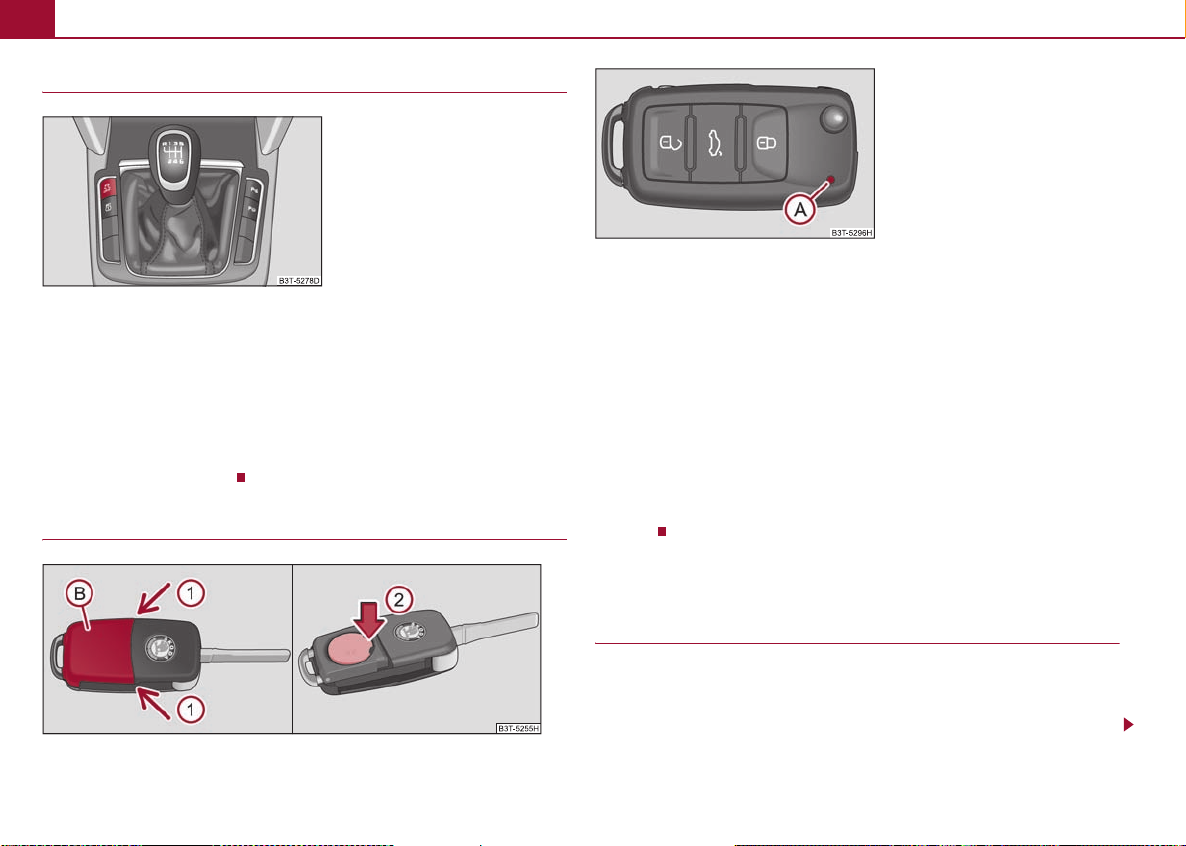
Control elements of the system:
• Sensor on the outside of the door handle for the front door ⇒ fig. 4 - serves for
locking the vehicle,
1
• Sensor on the inside of the door handle for the front door ⇒ fig. 4 - serves for
unlocking the vehicle.
Unlocking and locking the vehicle
Fig. 4 KESSY: Designation of the areas and unlocking/locking the vehicle
If a valid remote control key is located in the area or ⇒ fig. 4 of the vehicle, it is
possible to unlock the relevant door of this area. This mean s, if the key is located in the
area , you can unlock the front left door. If the valid key is located in the area , it
is possible to unlock the boot lid.
Unlocking the vehicle
– If you hold the door handle of the front door or cover the sensor ⇒ fig. 4 with
the whole palm of your hand, the vehicle is then unlocked.
B
Deactivating safe securing system*
– Use your fingers to cover the sensor twice within 5 seconds.
Unlocking and locking the boot lid
– If you press on the handle of the boot lid, the lid is then unlocked. If the vehicle is
fitted with the electric boot lid* system, the lid begins to open after pressing the
handle.
– If the boot lid is closed, it is locked.
Check locking
After locking the vehicle with the aid of the sensor ⇒ fig. 4, it is not possible to
unlock the vehicle with the aid of the sensor for 2 seconds. Thus, it is possible to
check if the vehicle is locked by pulling on the handle.
1
2
Note
If the vehicle battery or the battery in the remote control key is weak or discharged,
perhaps the vehicle cannot be unlocked or locked via KESSY. In such a case, use the
emergency unlocking or locking of the driver's door, see Owner's Manual.
Further possibilites of locking
Protection against inadvertently locking the key in the vehicle
If the key, which was used to lock the vehicle, remains in the vehicle in the area after
locking and closing all of the doors including the boot lid, the protection against inadvertently locking the key in the vehicle is activated and the vehicle unlocks itself again.
You are informed about the activation of the protection against inadvertently locking
the key in the vehicle by the turn signal lights flashing and the message Key i n vehic le
which appears in the information display*. Additionally, on vehicles which are fitted
with the anti-theft alarm system*, an audible signal sounds.
D
Locking the vehicle
– Close the driver or front passenger door.
– If you touch the sensor with your fingers, the vehicle is now locked (while doing
so do not hold the door handle, otherwise the vehicle cannot be locked).
Messages in the information display*
A few warning and information texts of the KESSY system in the information display*:
Electric boot lid* (Combi)4
A1A
A2A1A2A
A1A
A
A
No key
If you wish to start the engine and the system in the vehicle cannot detect a valid key,
the message No key “” is displayed. This can occur if the key is outside the vehicle, the
battery in the key is discharged, the key is defective or the electromagnetic field is
strongly disturbed.
Key not found
This message is displayed when the ignition is switched on or the engine is running and
the system cannot detect a valid key in the vehicle.
Keyless defective
There is a fault in the KESSY system, contact your specialist garage.
Renew key battery!
Low voltage is present in the battery of the remote control key, change the battery.
Parking the vehicle
If the vehicle is not unlocked within 60 hours, the sensors and ⇒ page 3, fig. 4
in the handle of the front passenger's door are automatically deactivated. For reactivation, one of the following conditions must be met:
Unlocking the driver's door with the aid of the sensor ⇒ page 3, fig. 4,
pressing the handle of the boot lid,
unlocking the vehicle using the button on the remote control key,
emergency unlocking of the driver's door (see Owner's Manual).
If the vehicle is not unlocked within 90 hours, the sensors and ⇒ page 3, fig. 4
in the handle of the driver's door are also automatically deactivated. For reactivation,
one of the following conditions must be met:
unlocking the vehicle using the button on the remote control key,
emergency unlocking of the driver's door (see Owner's Manual).
2
you lift your finger off the sensor , the closing process is interrupted. If you touch
the sensor again, the closing process of the windows and the panoramic sliding
1
roof continues.
If you immediately touch the sensor or pull on the handle during the closing
process of the windows and the panoramic sliding roof initiated by sensor , all of the
2
1
windows and the panoramic sliding roof are opened again.
Electric boot lid* (Combi)
Description
Fig. 5 Operation of the lid
Fig. 6 Operation of the lid - button on
the centre console
Convenience operation of the windows
If you hold your finger on the sensor ⇒ page 3, fig. 4 for more than 2 seconds while
locking the vehicle, the opened windows and the panoramic sliding roof are closed. If
1
There are several possibities for operating the electric boot lid:
By pressing the boot lid remote release button on the remote control key for
approx. 1 second,
Electric boot lid* (Combi) 5
AAA
using the handle ⇒ page 4, fig. 5 above the licence plate,
using the button on the bottom edge of the boot lid (only accessible when the
lid is opened),
using the button on the centre console ⇒ page 4, fig. 6.
B
WARNING
Always stand clear of the closing range of the lid when closing the lid - risk of
accident!
Caution
• In a critical situation, the movement of the lid can be stopped by applying an
abrupt and quick force against the lid.
• Before opening or closing the lid, check if there are any objects in the opening or
closing range which could obstruct the movement (e.g. a load on the roof luggage rack
or on the trailer etc.). - Risk of damaging the lid!
• Make sure that there is at least 10 cm of clearance above the opened boot lid (e.g.
distance from the garage ceiling). Otherwise, it may happen that the clearance above
the opened lid is no longer sufficient after relieving the vehicle of a load (e.g. after
unloading) - risk of damaging the lid!
• Do not try to manually close the lid during the electric closing process. Damage can
occur to the system of the electric boot lid.
• If you manually close the lid, ma ke su re t hat you pre ss t he lock located at the centre
edge of the lid while pressing down the lid above the Škoda logo.
Note
• If the electrical opening of the lid was triggered using the button on the remote
control key or the button on the centre console, an intermittent audible signal sounds
while the lid is moving.
• The electric boot lid is fitted with a force limiter. If the lid hits an obstacle when
closing, it stops and an audible signal sounds.
• Manually opening and closing the boot lid is only possible in exceptional cases, in
a slow manner and without sudden movements - if possible close to the centre of the
lid - ; by manipulating the lid on the sides, damage to the electric lid may occur.
• In certain circumstances, if the lid is loaded (e.g by a thick layer of snow), the
opening process of the lid can be interrupted. In order to ensure the electrical function
of the lid, relieve the lid.
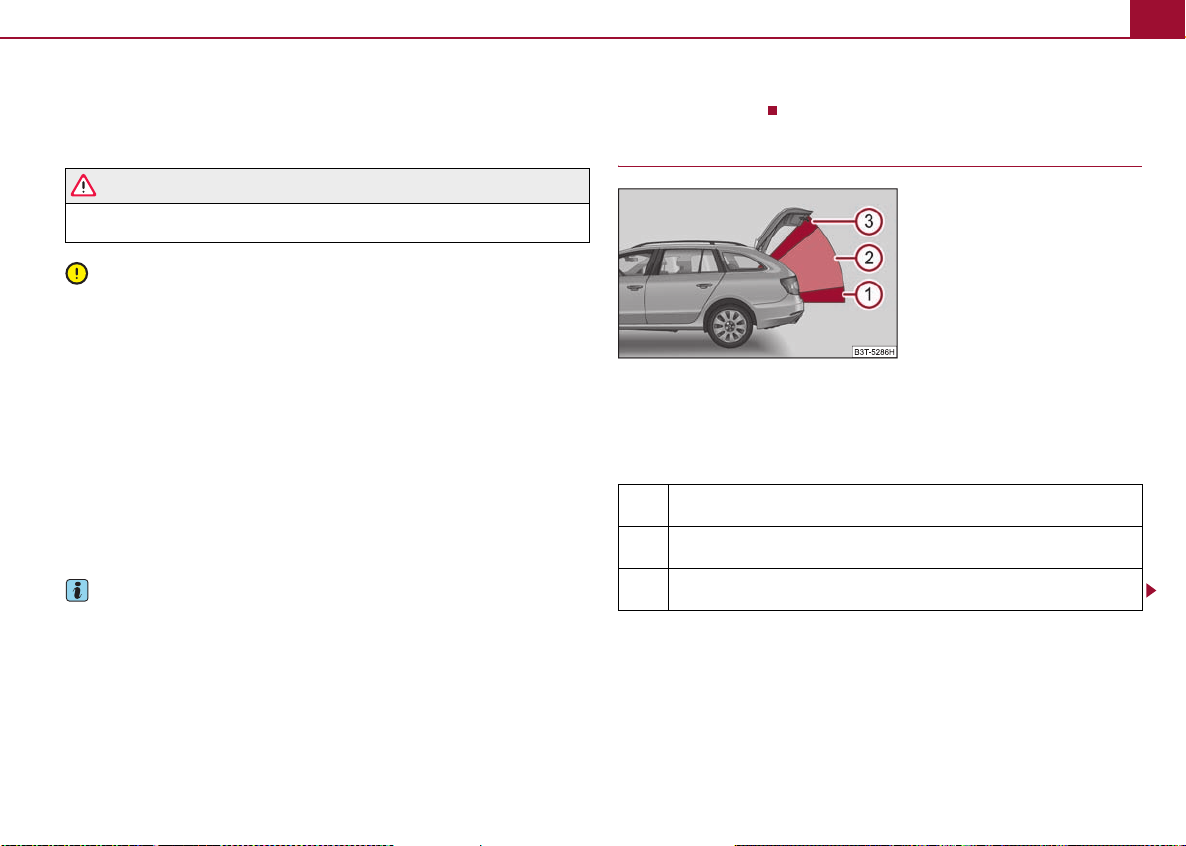
Description of the operation
Fig. 7 Designation of the areas
When operating the lid, the system distinguishes 3 areas ⇒ fig. 7 where the function of
the individual operating elements changes. The end positions of the lid - fully closed
in the secured lock and fully opened - differ as well.
Explanation of the symbol
Feasible action
Non-feasible action
Movement in the opposite direction to the previous movement

Electric boot lid* (Combi)6
A1A2A3A
A1A2A3A
ABA1A2A
A
A
A2A
A
Operation of the boot lid using the remote control key and the button on the
centre console
Action Closed lid
Opening
Stop
Closing
When the ignition is switched on, the operation of the boot lid does not function using
the remote control key.
If the vehicle was locked from the outside, the operation of the boot lid does not function using the button on the centre console ⇒ page 4, fig. 6.
Operation of the boot lid using the handle
Action Closed lid
Opening
Stop
Closing
The operation of the boot lid, using the handle ⇒ page 4, fig. 5, is only possible
when the vehicle is unlocked.
Area
A
Area
A
Opened lid
Opened lid
Operation of the boot lid using the inner button
Action Closed lid
Opening
Stop
Closing
Operating the boot lid with the inner button ⇒ page 4, fig. 5 is only possible when
the boot lid is opened.
Audible signals
Audible signals are active during the electrical operation of the lid. They serve as a
safety function and provide information about the success of a performed action.
Signals Status
Interrupted tone Open (using the button on the remote
1 continuous tone Force limiter
3 rising tones Confirmation of the storage of the lid
3 identical tones fault
Note
The expansion of the area ⇒ page 5, fig. 7 changes proportionally, depending on
the setting of the top position of the lid ⇒ page 7, “Setting the top position of the lid”.
When setting the top position of the lid in the area , the area is not active, the
expansion of the area changes proportionally to the set top position of the lid.
3
2
Area
B
control key or the button on the centre
console ⇒ page 4, fig. 6)
position
3
3
Opened lid
Emergency unlocking of the boot lid (Combi) 7
ABA
A
Setting the top position of the lid
If the space for opening the lid is restricted (e.g. height of garage) or for more convenient operation (e.g. according to a person's height), it is possible to set the boot lid in
the top position.
Setting the top position of the lid
– Stop the lid in the desired position (electrically or manually).
– Press the inner button ⇒ page 4, fig. 5 and hold it pressed for approx. 3
seconds. Storing the position in the memory of the control unit is confirmed with
an audible signal.
Deleting the set position of the lid
– Carefully lift up the lid manually to the maximum opening position.
– Hold the inner button pressed for approx. 3 seconds. An audible signal sounds
and the height which was originally set is deleted from the memory of the control
unit, while the basic position of the top lid position is again set.
B
Note
• The lid always opens at the height which was last stored in the memory of the
control unit.
• The top position which is reached when the lid opens automatically, is always
lower than the maximum top position which can be reached when the lid is opened
manually.
Operational malfunctions
If the battery is disconnected and reconnected while the boot lid is open, it is necessary to activate the system of the electric boot lid. Activating means the initialisation of
the control unit by manually closing the lid. Thus, the end position of the lid is stored
under fully closed in secured lock.
Possible malfunctions of the electric boot lid:
Examples of operational malfunctions
Description of the malfunction Possible solutions
The lid cannot be lifted out of the lock. Emergency unlocking of the lid ⇒ page 7
Remove the possible obstacle (e.g.
The lid does not react to an opening signal
The lid remains in the top position
snow), open the lid again ⇒ page 5,
“Description of the operation”
Press the handle on the lower edge of the
boot lid and pull the lid upwards
Manually close the lid (slowly and without sudden movements)
Note
Contact your specialist garage if there is a malfunction of the electric boot lid.
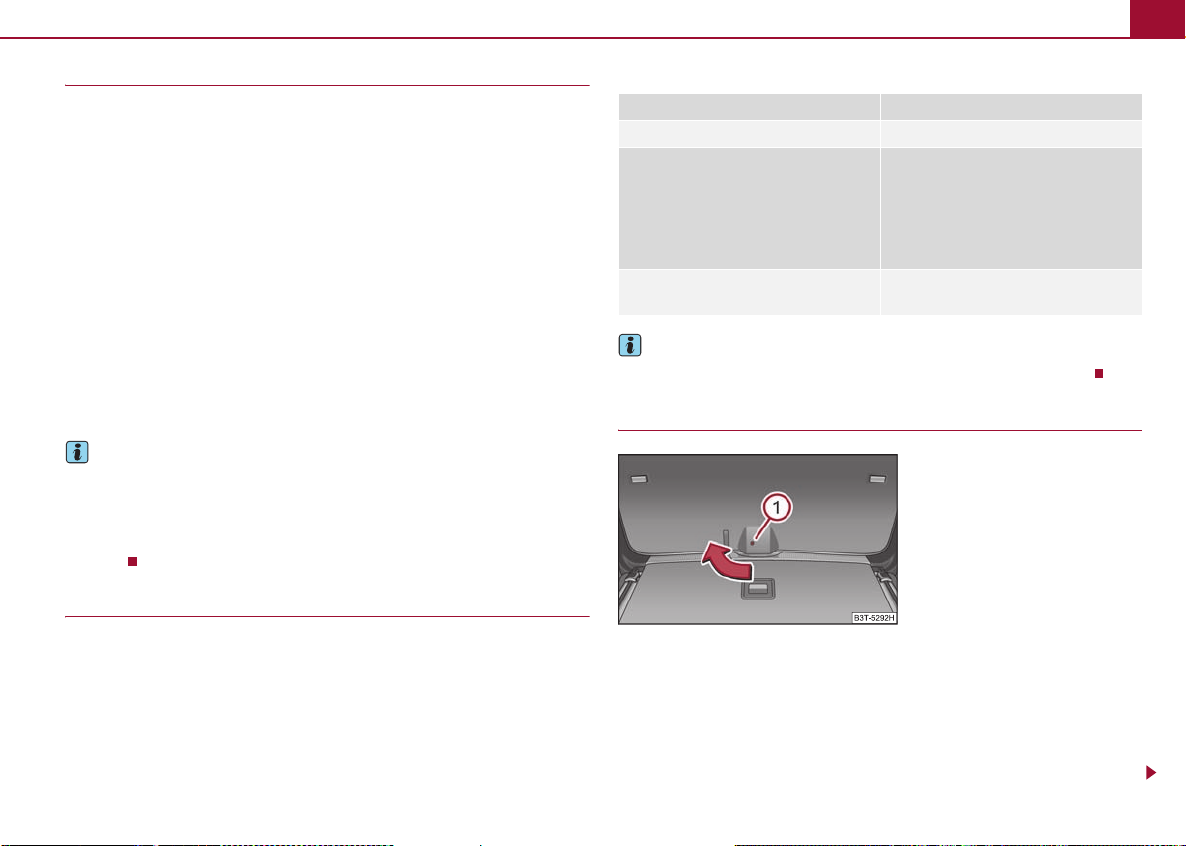
Emergency unlocking of the boot lid (Combi)
Fig. 8 Emergency unlocking of the boot
lid
If there is a fault in the central locking, you can open the boot lid as follows:
– Fold the backrest of the rear seat forwards (see Owner's Manual).
– Guide a screwdriver into the opening ⇒ fig. 8 up to the stop.
– You can unlock the lid by moving it in the direction of the arrow.
– Open the boot lid from the outside.
1
Panoramic sliding roof* (Combi)8
A
ADABA
A
Caution
In an emergency, you can unlock the boot lid with the vehicle key, however only in a
critical situation - risk of damaging the key.
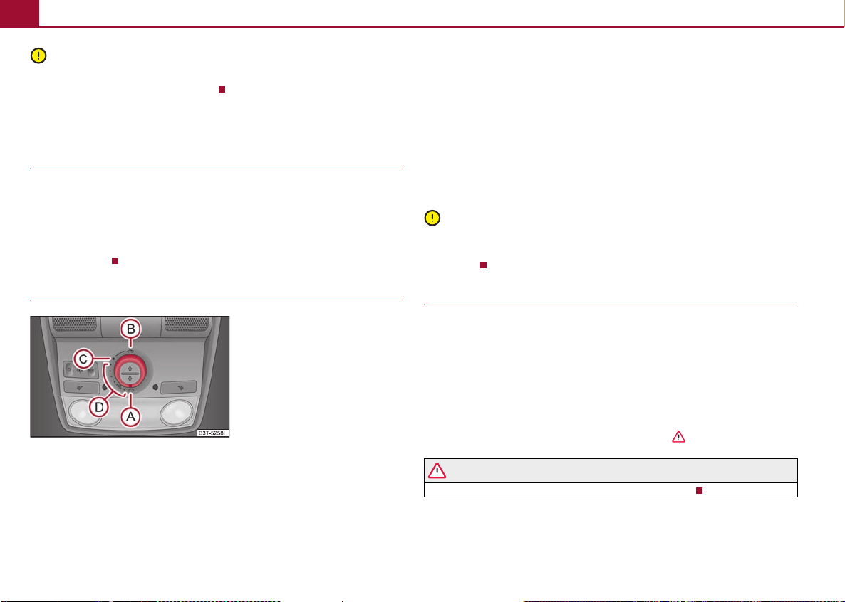
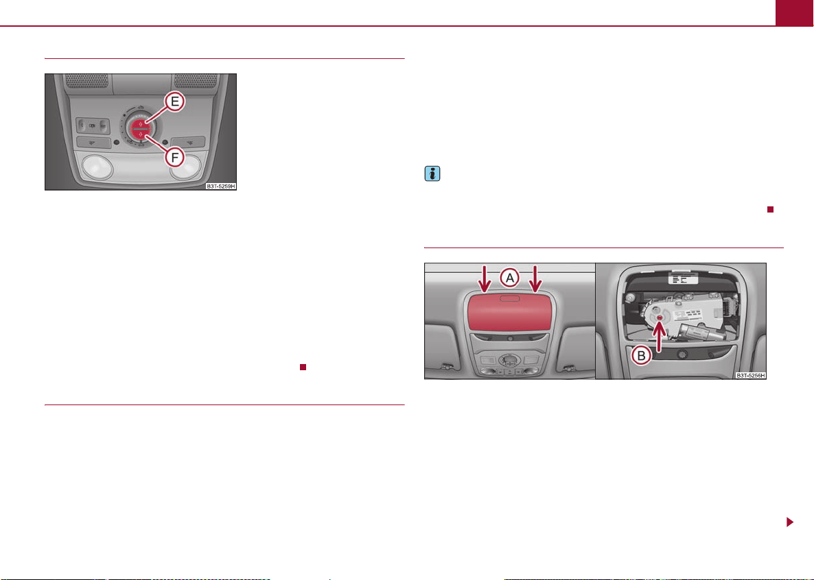
Panoramic sliding roof* (Combi)
Introduction
The panoramic sliding roof with sun screen can only be operated with the control dial
when the ignition is switched on ⇒ fig. 9. The control dial has several positions.
After switching off the ignition, it is still possible to open, close and tilt the panoramic
sliding roof or the sun screen for approx. 10 minutes. However, it is no longer possible
to operate the panoramic sliding roof and the sun screen the moment you open one
of the front doors.
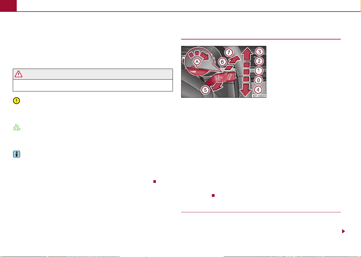
Opening and tilting the panoramic sliding roof
Fig. 9 Control dial for the panoramic
sliding roof
Comfort position
– Turn the switch to position ⇒ fig. 9.
Open partially
– Turn the switch to a position in area .
C
Open fully
– Turn the switch to position and hold it in this position (spring-tensioned posi-
tion).
Tilting and closing
– In order to tilt, press the switch on the recess in the direction of the roof.
– In order to close, press down the switch on the recess and then push it forwards.
When the panoramic sliding roof is in the comfort position, the intensity of the wind
noise is reduced.
Caution
It may be necessary during winter to remove any ice and snow in the area of the panoramic sliding roof before opening it, in order to prevent damaging the opening
mechanism.
Closing the panoramic sliding roof
Closing
– Turn the switch to position ⇒ fig. 9.
Force limiter
The panoramic sliding roof is fitted with a force limiter. The panoramic sliding roof
stops and moves back several centimetres when it cannot be closed because there is
something in the way (e.g. ice). You can close the panoramic sliding roof fully without
force limiter by pressing the switch to the position ⇒ fig. 9 at the front for as long
as it takes for the panoramic sliding roof to close fully ⇒ .
A
A
WARNING
Carefully close the panoramic sliding roof - risk of injury!
Panoramic sliding roof* (Combi) 9
A
AEA
AFA1A
A1A
A
A
Opening and closing the sun screen
Fig. 10 Buttons for sun screen
You can open or close the sun screen separately with the aid of the buttons ⇒ fig. 10.
Opening
– Briefly press the button ⇒ fig. 10 in order to fully open.
– Press the button and hold it pressed in order to open in the desired position.
The opening process stops when one releases the button.
E
Closing
– Briefly press the button ⇒ fig. 10 in order to fully close.
– Press the button and hold it pressed in order to close in the desired position.
The closing process stops when one releases the button.
F
Convenience operation
The panoramic sliding roof and the sun screen can be operated from the outside using
the remote control key or when using the KESSY* system w ith the aid of t he sens or
⇒ page 3, fig. 4.
Closing the panoramic sliding roof
– Hold down the lock button on the remote control key, or when using the KESSY*
system keep your finger on the sensor ⇒ page 3, fig. 4, until the panoramic
sliding roof is closed. The panoramic sliding roof and the sun screen are closed
together.
1
After releasing the button, or lifting your finger off the sensor when using the
KESSY* system, the closing process is immediately interrupted.
Tilting the panoramic sliding roof
– Hold down the unlock button on the remote control key, or when using the KESSY*
system keep your finger on the sensor ⇒ page 3, fig. 4, until the panoramic
sliding roof is tilted. When tilting the panoramic sliding roof, the sun screen opens
at the same time.
1
Note
• The force limiter also operates for convenience closing.
• The panoramic sliding roof cannot be opened via the convenience operation.
Emergency operation
Fig. 11 Detail o f the headliner: Points for positioning a s crewdriver (left) and the emergency
operation (right)
You can close and/or open the panoramic sliding roof by hand if the system is defective.
– Position the flat blade of a screwdriver carefully against the rear edge of the cover
of the electrical drive ⇒ fig. 11.
–Pull the cover down.
– Insert an Allen key, Group 4, up to the stop into the opening and close or open
the panoramic sliding roof.
A
B

Daylight driving lights*10
AAA
– Press on the cover again by first of all inserting the plastic lugs and then pushing the
cover up.
– Have the malfunction rectified by a specialist garage.
Note
After each emergency operation, it is necessary to initialise the roof ⇒ page 10, “Initia lising the panoramic sliding roof”.
Initialising the panoramic sliding roof
After disconnecting and reconnecting the battery, the panoramic sliding roof and the
sun screen must be initialised.
Hold down the control dial in the position ⇒ page 8, fig. 9 for approx. 10 seconds
in order to intialise the panoramic sliding roof.
Press the switch ⇒ page 9, fig. 10 for approx. 10 seconds in order to initialise the
sun screen.
If the panoramic sliding roof or the sun screen is not fully closed while disconnecting
and reconnecting the battery, first of all the panoramic sliding roof or the sun screen
must be closed ⇒ page 8, “Closing the panoramic sliding roof” ⇒ page 9, “Opening
and closing the sun screen”. Only then the initialisation can be performed.
F
Daylight driving lights*
In some countries, the national legal provisions require that the parking lights com e on
together with the bulbs for daylight d riving lights when activating the function daylight
driving lights.
Furthermore, after switching on the ignition when the parking lights are switched on,
the door handle lighting* comes on.
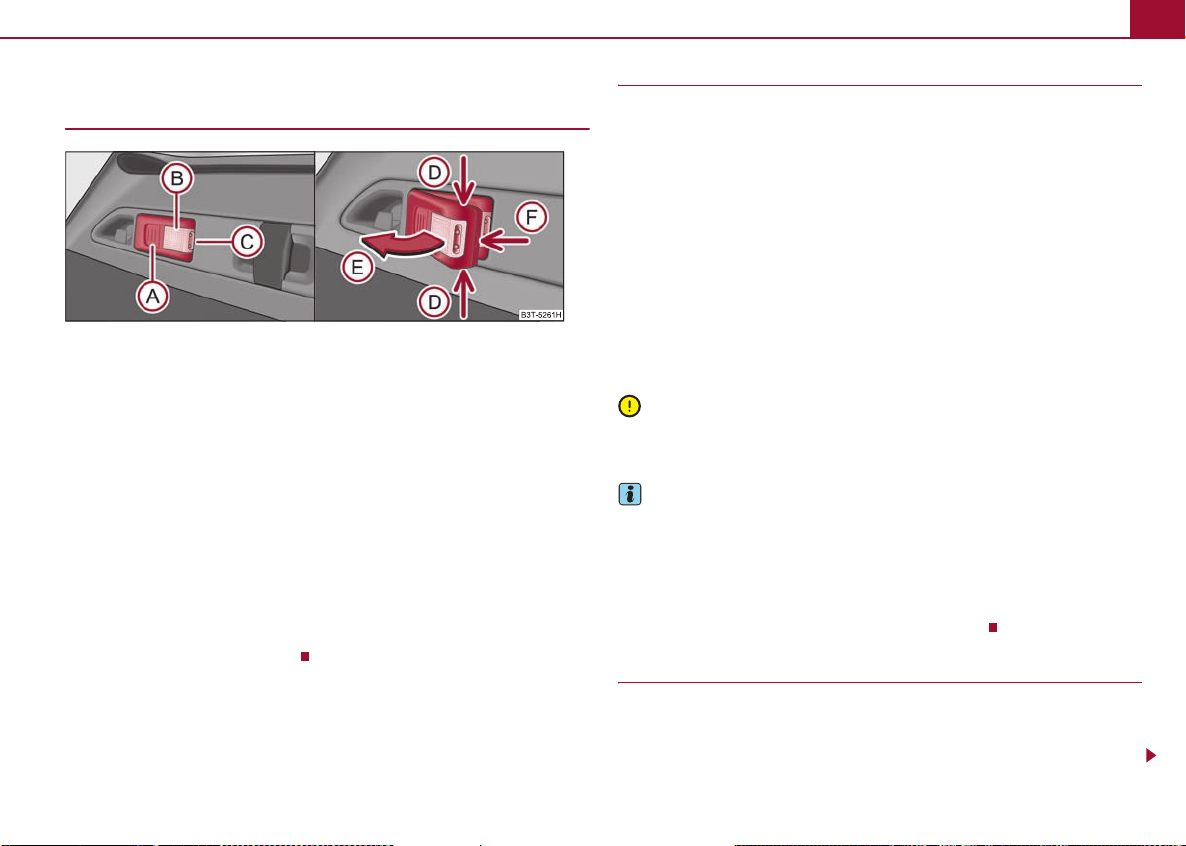
Rear reading lights* (Combi)
Valid for vehicles which are fitted with a panoramic sliding roof.
Fig. 12 Detail of the headliner: Rear
reading lights
Switching the interior light on
– Press the cover glass in the area of the symbol ⇒ fig. 12.
Switching the interior light off
– Press the cover glass in the area of the symbol O.
Door contact setting
– Position the cover glass into middle position .
Door warning light*
Front vehicle interior lighting
Two diffuse lights* are integrated in the interior lighting, which illuminates the shift
lever and the middle of the dash panel. They are switched on automatically when
switching on the parking light.
The warning light* is located in the door trim panel below.
Luggage compartment light (Combi) 11
A
ACA
AEAAAAA
A
Luggage compartment light (Combi)
Removeable lamp
Fig. 13 Removeable lamp
A removeable lamp is fitted on the left side of the luggage compartment. This lamp has
two functions:
• Lighting of the luggage compartment - it illuminates part ⇒ fig. 13 (the lamp is
in the holder),
B
• Portable lamp - it illuminates part (the lamp has been removed from the
holder).
If the lamp is in the holder, it is automatically switched on after opening the boot lid. If
the lid remains open for more than about 30 minutes, the light switches off automatically.
The lamp is supplied by three rechargeable batteries type AAA with a capacity of 600
mAh. The rechargeable batteries are constantly charged when the engine is running. It
takes approx. 3 hours to fully charge the rechargeable batteries.
The lamp is fitted with magnets. Therefore it is possible to attach the lamp, for example
on the vehicle body, after removing it.
Taking out the lamp
Taking out the lamp
– Grasp the lamp at the points of the arrows ⇒ fig. 13 and swivel it in the direc-
tion of arrow .
D
Placing the lamp again in its holder
– First of all place the lamp, which is switch ed off, in the holder on the side facing the
boot lid and then press on the lamp from the other side until it is heard to lock in
place.
Operation of the lamp
• If you press the button once, the lamp lights up with 100% light intensity.
• If you press the button again, the lamp lights up with 50% light intensity.
• If you press the button once again, the lamp goes out.
Caution
The removeable lamp is not watertight and therefore must be protected against moisture.
Note
A
• If the lamp is not correctly inserted in the holder, it does not light up when opening
the boot lid and the rechargeable batteries are not charged.
• If the lamp is not switched off, however it is correctly inserted in the holder, the
bulbs in the front part ⇒ fig. 13 of the lamp are automatically switched off.
C
• The removed lamp can remain lit for a maximum of 24 hours with 100% light inten-
sity and for a maximum of 48 hours with 50% light intensity.
Replacing the rechargeable batteries of the lamp
You should proceed as follows if you wish to replace the faulty rechargeable batteries
yourself:
– Take out the lamp.
Windscreen wipers12
A
A
A
A
– Lever off the cover of the rechargeable batteries with a narrow and pointed object
at the point of the lock-off clips ⇒ page 11, fig. 13.
– Remove the faulty rechargeable batteries from the lamp.
– Insert the new rechargeable batteries.
– Insert the cover of the rechargeable batteries and press on it u ntil it is h eard t o loc k
in place.
F
WARNING
Pay particular attention when using the narrow and pointed object to change
the rechargeable batteries - risk of injury.
Caution
We recommend having the faulty rechargeable batteries replaced by a specialist
garage. If the lamp is not correctly opened, it can be damaged.
For the sake of the environment
Dispose of the faulty rechargeable batteries in accordance with environmental regulations.
Note
• Pay attention to the correct polarity when replacing the rechargeable batteries.
• The replacement rechargeable batteries must have the same specification as the
original rechargeable batteries. If other types of rechargeable batteries are used, the
power output can be reduced and it can lead to a malfunction of the lamp.
Windscreen wipers
Rear window wiper (Combi)
Fig. 14 Windscreen wiper lever
Wiping the rear window pane*
– Push the lever away from the steering wheel into position ⇒ fig. 14, the wide-
screen wiper will operate every 6 seconds.
Automatic wipe/wash for the rear window pane*
– Press the lever from the steering wheel forward into the sprung position , the
wash system sprays immediately, the windscreen wiper starts wiping a little later.
As long as you hold the lever in this position, the wi per operates as well as the wash
system.
– Letting go of the lever will cause the windscreen wash system to stop and the wiper
to continue for another 2 - 3 wiper strokes (depending on the period of spraying of
the windscreen). The lever will stay in position after releasing it.
The rear window will be wiped again if the front window wipers are on when reverse
gear is selected.
6
6
7
Position of the rear window wiper
Each second time the ignition is switched off, the wiper blade is tilted. Thus, the life of
the wiper blade is prolonged. As standard this function is activated and it can be deactivated as follows:
Exterior mirrors 13
A
A2A3A
A
A2A
Deactivating
– Switch on the ignition.
– Push the operating level into the position ⇒ page 12, fig. 14 five times in
succession within 5 seconds.
– Switch off the ignition. After switching on the ignition again, the position of the rear
window wiper is deactivated.
The activation of the position of the rear window wiper is carried out in the same way
as the deactivation.
6
Automatic rear window wiper* (Combi)
If the windshield wiper lever is in the position or , the rear window wiper carries
out a wiping process every 30 seconds or 10 seconds at a speed above 5 km/h.
When the rain sensor* is active (the lever is in the position ) the function is only
active if the front window wipers continue to operate (no break between each wiping
process).
Activation/deactivation
The function of the automatic rear window wiper is activated/deactivated in the information display* in the menu:
Setup
Lights & Vision (Lights & Vision)
Rear wiper
1
Note
The function of the automatic rear window wiper is only valid for Combi vehicles which
are equipped with the information display*. The function is activated in the factory.
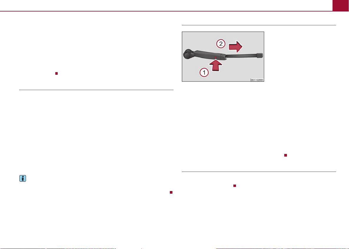
Replacing the wiper blade for rear window (Combi)
Fig. 15 Wiper blade for rear window
Taking off the wiper blade
– Fold windscreen wiper arm out from the windscreen and position the wiper blade
at right angles to the wiper arm ⇒ fig. 15.
– Hold the window wiper arm at the top end with one hand.
– With the other hand unlock the locking button and remove the wiper blade in
the direction of arrow .
1
Attaching a wiper blade
– Position the wiper blade onto the wiper arm and lock the locking button .
– Check whether the wiper blade is correctly attached.
1
Exterior mirrors
It is only possible to fold in both exterior mirrors when the ignition is switched on and
at a speed of up to 15 km/h.

Adjusting the front seats electrically*14
A1A
A
Adjusting the front seats electrically*
Assigning the remote control key to the memory buttons
On vehicles which are equipped with the KESSY* system, the following procedure for
assigning the remote control key to the memory buttons exists for electrically adjustable front seats and mirrors*.
– Switch the ignition off within 10 seconds after storing the setting.
– Open the driver door.
– Press the unlock button on the remote control key within 10 seconds.
After the successful assignment, the turn signal lights flash and an audible signal will
sound as a confirmation. The setting is stored with the memory button which you have
selected.
Rear seats
Folding the rear seats forwards (Combi)
Fig. 16 Folding the seat cushion
forwards
To enlarge the luggage compartment, the rear seats can be folded forwards, if necessary fold the seat cushions forwards.
Folding the seat cushion forwards
– Pull up the seat cushion in direction of arrow ⇒ fig. 16 and fold forwards in
direction of arrow .
2
Note
In order to achieve a loading space as horizontal as possible, the rear head restraints
can be removed before folding the seat backrests forwards. Store the removed head
restraints in such a way that they cannot be damaged or soiled.
Luggage compartment
Fixing nets - Net programme* (Combi)
Fig. 17 Fixing nets
Fixing examples of the fixing net as a horizontal pocket ⇒ fig. 17 on the left and a
vertical pocket on the right.
Note
The hooks located on both sides of the luggage compartment are only designed for
fixing the fixing net.
A

Luggage compartment 15
A
A
A1A
A
Folding hooks (Combi)
Fig. 18 Luggage compartment: folding
hooks
Folding hooks for attaching small items of luggage, such as bags etc., are provided on
both sides of the luggage compartment ⇒ fig. 18.
Note
An item of luggage weighing up to 7.5 kg can be attached to the hook.
Fixing floor covering of the luggage compartment (Combi)
Fig. 19 Luggage compartment: Fixing
the floor covering
A hook is located on the underside of the floor covering. When handling the spare
wheel*, you can fix the raised floor covering with the hook on the frame of the luggage
compartment.
Foldable luggage compartment cover (Combi)
Fig. 20 Luggage compartment: foldable luggage compartment cover
Pulling out
– Pull the foldable luggage compartment cover as far as the stop into the secured
position ⇒ fig. 20.
2
Fold ing
– Press the cover in the handle area in direction of arrow ⇒ fig. 20, the cover rolls
up automatically into position . The cover is fully rolled up by pressing once
again.
3
Removing
– The fully folded luggage compartment cover can be removed to transport bulky
goods by pressing on the side of the cross rod in direction of arrow ⇒ fig. 20
and taking it out by moving it in direction of arrow .
5
4
WARNING
No objects should be placed on the luggage compartment cover.

Variable loading floor* (Combi)16
A1A
A1A2ACA
Automatic foldable luggage compartment cover* (Combi)
The automatic rolling up of the foldable luggage compartment cover
enables an easier entry into the luggage compartment.
– Open the boot lid. The foldable luggage compartment cover rolls up automatically
in the position ⇒ page 15, fig. 20.
– The cover rolls up fully by pressing the cover in the handle area in direction of
When the boot lid is opened quickly, the automatic rolling up of the foldable luggage
compartment cover is blocked for a delay time of approx. 2 seconds.
The function of the automatic rolling up of the foldable luggage compartment cover
can be activated/deactivated in the information display* in the menu:
SETUP
3
arrow .
Autom. blind
Variable loading floor* (Combi)
Introduction
The variable loading floor makes handling of bulky items of luggage easier.
Note
• The maximum load of the variable loading floor is 75 kg.
• The space below the variable loading floor can be used for stowing objects, for
example the fixing set, the removed foldable luggage compartment cover, the bicycle
holder etc.
Partially pulling out the variable loading floor*
Fig. 21 Luggage compartment: partially pulling out the variable loading floor
The variable loading floor can be partially pulled out over the rear bumper. The variable loading floor which is pulled out in such a way is solely used as a seat, for example
for changing shoes. When pulling out the variable loading floor, the front edge (close
to the rear seats) is lifted at the same time. Thus, small objects can no longer fall into
the space between the luggage compartment floor and the variable loading floor.
– Grasp the rear part of the floor at the handle, raise it slightly in direction of arrow
⇒ fig. 21 and pull it over the bumper in direction of arrow until it engages
in the opening ⇒ fig. 21.
– Grasp the rear part of the floor at the handle, raise it slightly in direction of arrow
1
and push it forwards up to the stop in order to push in the variable loading floor.
Caution
Ensure that the raised front edge of the variable loading floor is not damaged.

Variable loading floor* (Combi) 17
A1AAAAA1A
A
A3A
Dividing the luggage compartment with variable loading floor*
Fig. 22 Divide the luggage compartment
The luggage compartment can be divided with the variable loading floor.
– Grasp the rear part of the floor at the handle, raise it in direction of arrow
⇒ page 16, fig. 21 and insert the rear edge in one of the openings ⇒ fig. 22.
The variable loading floor is secured in the openings against movement.
The variable loading floor can be pulled out some more before dividing the luggage
compartment with the variable loading floor ⇒ page 16. This enlarges the space
between the rear seats and the separation.
Caution
Ensure that the raised front edge of the variable loading floor is not damaged.
Removing and installing the variable loading floor* (Combi)
Fig. 23 Luggage compartment: fold up variable loading floor
Fig. 24 Luggage compartment: remove variable loading floor
You can remove and reinstall the variable loading floor, if necessary.
Removing the variable loading floor
– Grasp the rear part of the floor at the handle, raise it slightly in direction of arrow
⇒ fig. 23 and pull it over the bumper in direction of arrow until it engages
in the opening ⇒ fig. 24.
– You can fold together the loading floor by moving it in direction of arrow
⇒ fig. 23.
– Press the safety buttons ⇒ fig. 24 and remove the floor.
C
A
2
Installing the variable loading floor
– Fold together the floor and place it on the carrier rail.

Variable loading floor* (Combi)18
ABACA
A
A2A3A4A5A
– Push the floor forwards until it engages in the openings ⇒ page 17, fig. 24 in the
carrier rails.
– Ca refu lly pres s on t he po int s of t he op eni ngs o n th e flo or un til it is hea rd to l ock
in place, if necessary press the safety buttons .
A
WARNING
Pay attention when installing the variable loading floor that it is correctly
attached. If this is not the case, there is a risk of injury for the occupants.
Fixing set* (Combi)
Fig. 25 Telescopic pole and tensioning strap
The fixing set can be used for dividing the luggage compartment or for securing the
objects which are being transported.
Telescopic pole
– Insert the holder for the telescopic pole on the left and right into the openings of
the carrier rails.
– Press the top part of the holder in direction of arrow ⇒ fig. 25 and push it at the
same time in the desired position, arrow .
– Ensure that the holder is correctly interlocked.
1
Tensioning strap
– Insert the holder of the tensioning strap into the opening of the left or right carrier
rail.
– Press the holder in direction of arrow ⇒ fig. 25 and push it at the same time in
the desired position, arrow .
– Ensure that the holder is correctly interlocked.
– Place the object which should be fastened behind the tensioning strap.
– Press the button on the top side of the holder and tighten the strap.
WARNING
The objects in the luggage compartment must be firmly secured with the fixing
set so that they cannot move freely and uncontrollably in order to prevent
damage to objects or injuries to the occupants.
Note
• Do not use the fixing set for securing objects which might damage the fixing set.
• The tensioning strap can also be fully reeled up by pressing the button
⇒ fig. 25.
Moveable lashing eyes* (Combi)
Fig. 26 Moveable lashing eyes
5

Net partition* (Combi) 19
A1A2A
AAABACA
ACACABA
AAABACA
ACA
Four moveable lashing eyes, which can be used for example for attaching the fixing
net, are located in the luggage compartment.
– Press the button ⇒ page 18, fig. 26 and push the lashing eye in the desired
position, arrow .
– Fold up the clamp ⇒ page 18, fig. 26 and fix, for example, the fixing net.
3
Net partition* (Combi)
Use the net partition behind the rear seats
Fig. 27 Pull out the net partition
Pulling out
– Pull the net partition at the bracket ⇒ fig. 27 out of the housing in direction
of the holders .
– Insert the cross rod into one of the mounts and push the cross rod forwards.
– In the same way, fix the cross rod to the other side of the vehicle, mount .
Fold ing
– Pull the cross rod back slightly, first on the one side then on the other side and take
the cross rod out of the mounts ⇒ fig. 27.
– Hold the cross rod in such a way that the net partition can roll up into the housing
slowly and without damage.
C
If you wish to use the entire luggage compartment, you can remove the foldable
luggage compartment cover ⇒ page 15.
WARNING
First check for yourself that the cross road is inserted into the mounts in the
front position!
C
Using the net partition behind the front seats
Fig. 28 Pull out the net partition
Pulling out
– Fold the rear seats forwards (see Owner's Manual).
– Pull the net partiton at the bracket ⇒ fig. 28 out of the housing
– Insert the cross rod into the mount first on the one side and push the cross rod
forwards.
– In the same way, fix the cross rod to the other side of the vehicle, mount .
C
Fold ing
– Pull the cross rod back slightly, first on the one side then on the other side and take
the cross rod out of the mounts ⇒ fig. 28.
– Hold the cross rod in such a way that the net partition can roll up into the housing
B
slowly and without damage.
– Fold the rear seats back into their original position.

Power socket in the luggage compartment (Combi)20
A
AAA
A
A
WARNING
• The belt locks and the belts must be in their original position after folding
back the seat cushions and the seat backrests - they must be ready to use.
• The seat backrests must be securely interlocked in position so that no
objects in the luggage compartment can slide forwards if there is sudden
braking - risk of injury!
• First check for yourself that the cross road is inserted into the mounts in
the front position!
C
• Pay attention that the rear seat backrest is correctly interlocked. It is only
then that the three-point seat belt for the middle seat can reliably fulfil its
function.
Removing and installing the net partition housing (Combi)
Fig. 29 Rear seats: Net partition housing
Removing
– Fold the rear seats forwards (see Owner's Manual).
– Open the right rear door.
– Push the net partition housing ⇒ fig. 29 in the directio n of arro w and ta ke it
out of the mount of the rear seats in the direction of arrow .
1
2
– Push the net partition housing in the opposite direction of arrow as far as the
stop.
– Fold the rear seats back into their original position.
1
WARNING
Pay attention that the rear seat backrest is correctly interlocked. It is only then
that the three-point seat belt for the middle seat can reliably fulfil its function.
Power socket in the luggage compartment
(Combi)
Fig. 30 Luggage compartment: Power
socket
– Open the cover of the power socket ⇒ fig. 30.
– Connect the plug of the electrical appliance to the socket.
You can only use the power socket for the connection of approved electrical accessories with a power uptake up to 120 watts. The vehicle battery will be discharged in the
process if the engine is stationary.
Installing
– Position the net partition housing into the mounts of the rear seat backrests.

Removeable through-loading bag* 21
A
A
ABA
A
ABAAA
Removeable through-loading bag*
The removeable through-loading bag is solely used for transporting
skis.
Fig. 31 Securing the through-loading
bag
The through-loading bag is foreseen for four pairs of skis. The total weight of the skis
which are transported must not exceed 17 kg.
Securing
– Tighten the strap ⇒ fig. 31 on the free end around the skis in front of the bind-
ings.
– Fold the seat backrest a little forward.
– Guide the securing strap through the opening in the seat backrest around the
upper part of the seat backrest.
– Then push the seat backrest back into the upright position until the locking button
clicks into place - check by pulling on the seat backrest.
– Insert the securing strap into the lock until it is heard to lock in place.
On vehicles fitted with a n et partition, guide the securing strap around the net partition housing when the net partition is rolled up. After fixing the net partition in place,
it is not longer possible to unroll the net partition.
A
B
C
B
WARNING
• After placing skis into the through-loading bag, you must secure the bag
with the securing strap .
• The strap must hold the skis tight.
• Make sure that the strap holds the skis in front of the binding (see also
imprint on the removeable through-loading bag).
A
Lockable side compartment* (Combi)
Fig. 32 Luggage compartment: Lockable
side compartment
– Open the compartment by pulling at the handle in direction of arrow ⇒ fig. 32.
The CD changer*, the TV Tuner* are housed in this compartment.
You can also house the first-aid box * and the warning triangle* in this compartment.

Non-lockable side compartment (Combi)22
Non-lockable side compartment (Combi)
Fig. 33 Non-lockable side compartment
The cover of the side compartment can be removed and thus the luggage compartment can be enlarged.
– Grasp the cover on the top part and carefully remove it in direction of arrow
⇒ fig. 33.
Caution
Make sure that the cover of the side compartment is not damaged when installing or
remov ing.
Loading the luggage compartment
Caution
Make sure that transported objects with sharp edges do not damage the following:
• heating elements in the rear window,
• elements of the aerial integrated in the rear window (Superb),
• elements of the aerial integrated in the rear side windows (Combi).
Starting-off and driving - KESSY system*
Introduction
The KESSY system makes it possible to switch the ignition on/off and to start/stop the
engine without actively using the key.
Unlocking and locking the steering
Fig. 34 Starter button
It is necessary that a valid key is in the vehicle in order to unlock the steering.
Unlocking the steering
– Open the driver door and enter the vehicle.
– When closing the driver door, the steering is unlocked.
Locking the steering
– Bring the vehicle to a stop.
– Switch off the engine and/or the ignition by pressing the starter button ⇒ fig. 34.
– When opening the driver door, the steering is locked.
The steering is also locked after locking the vehicle.
If the steering is locked and the KESSY system does not manage to unlock the steering
lock the first time (e.g. if the wheels rest against the curb), the attempt will be repeated
twice by the system.

Starting-off and driving - KESSY system* 23
If then the steering lock can still not be unlocked, you will be asked by the system, by
means of a message in the information display* Move steering wheel!, to move the
steering wheel and 3 more attempts to unlock will be made after 2 seconds.
If the steering lock can still not be unlocked afterwards, the message in the information
display* Steering wheel still locked is displayed.
It is necessary to eliminate the possible cause which prevents the unlocking and repeat
the attempt to unlock the steering.
Engine protection for electric steering lock
The electric steering lock has an engine protection which slows down the locking and
unlocking of the steering if the starter button is pressed repeatedly at short intervals.
Note
• After pressing the starter button while the steering is locked, the steering is
unlocked, the electrical components are activated (e.g. radio, navigation system etc.)
and the igntion is switched on.
• If you do not exit or enter the vehicle again using the valid key after locking the
steering, however you wish to unlock the steering, you must press the starter button.
At the same time, electrical components are activated (e.g. radio, navigation system
etc.) and the ignition is switched on.
• If you switch off the ignition or the engine by pressing the starter button and if the
driver door is already opened, the steering will not lock. The driver door must be
opened and closed again in order to lock the steering.
Switching on the ignition
It is necessary that a valid key is in the vehicle and that the steering is unlocked in order
to switch on the ignition.
– The ignition is switched on by briefly pressing the starter button ⇒ page 22,
fig. 34.
Switching off the ignition
– The ignition is switched off by briefly pressing the starter button ⇒ page 22, fig. 34.
The ignition can be switched off up to a speed of 2 km/h.
On vehicles fitted with a manual gearbox, the clutch must not be pressed after
switching off the ignition otherwise the system would try to start.
On vehicles fitted with an automatic gearbox, the selector lever must be in the position
P or N and the brake pedal must not be pressed.
Emergency ignition shutoff system
In an emergency it is possible to switch off the ignition even at speeds greater than 2
km/h, by way of the so-called emergency ignition shutoff system.
– Press the starter button ⇒ page 22, fig. 34 fo r lo nge r th an 1 sec ond or p res s it twi ce
within 1 second.
WARNING
Never switch off the ignition while driving, otherwise the steering and brake
assist do no longer function - risk of accident!
Starting the engine
It is necessary that a valid key is in the vehicle, the steering is unlocked and the ignition
is switched on in order to start the vehicle. On vehicles with manual gearbox hold the
clutch pedal pressed or, on vehicles with automatic gearbox, hold the brake pedal
pressed in order to start the vehicle.
Petrol engines
– Press the starter button ⇒ page 22, fig. 34 until the engine has started.
Diesel engines
– If the starter button is pressed during the whole preglow period, the engine starts
after the warning light has gone out.
The diesel engine can also be started by pressing the starter button, the ignition is
switched on and the preglow warning light lights up. You must wait until the

Starting-off and driving - KESSY system*24
preglow warning light goes out and then press the starter button again until the
engine starts.
If in an emergency, the engine must be started quickly (e.g. in a critical situation), you
can start the engine by pressing the starter button again before the preglow warning
light goes out.
WARNING
Never leave the key in the vehicle in the area where there are children, because
they can easily start the vehicle - risk of accident!
Note
If the steering is locked while the engine is started, it is unlocked by pressing the starter
button, the electrical components (e.g. radio, navigation system etc.) are activated, the
ignition is switched on and the engine is started.
Emergency start-up of engine
Fig. 35 Emergency start-up of vehicle
If the authorised key is not successfully recognised, the message No key “” is shown in
the information display* and the start-up of the engine must be carried out.
– Press the starter button ⇒ fig. 35 and then hold the key at the starter button or
– press the starter button directly with the key.
Note
During an emergency start-up of the engine, the correct orientation of the key must be
kept ⇒ fig. 35.
Switching the engine off
– Bring the vehicle to a stop.
– Switch off the engine by pressing the starter button ⇒ page 22, fig. 34, doing so
switches off the ignition at the same time.
Note
The KESSY system is protected against inadvertently switching off the engine while
driving, this means that the engine can only be switched off in an emergency
⇒ page 23.
Messages in the information display*
If the electric lock of the KESSY system is defective, a fault message is shown in the
information display.
Steering column lock: Workshop!
If this message and in addition the symbol are shown in the information display,
you can continue the trip with extra care. The vehicle must be immediately taken to a
specialist garage.
Steering column lock defective.
If this message and in addition the sym bol are shown in the information display, the
vehicle must not be driven and it must be taken to a specialist garage. After switching
off the ignition, it is then no longer possible to lock the steering, to activate the electrical components (e.g. radios, navigation systems), to switch on the ignition again and
to start the engine.

Driving in an economical and environmentally conscious manner 25
AAABAAAAA
Move selector lever to position P/N!
This message is shown in the information display if the selector lever is not in the position P or N, when locking the steering, switching the ignition on/off or when starting
the engine.
Move selector lever to position P!
This message is shown in the information display if the selector lever is in the position
P when opening the driver door and the ignition is switched off, or if it is not in the
position P, when switching off the ignition while the driver door is open. The message
disappears after a few seconds by switching on the ignition or by moving the selector
lever into the position P.
1)
1)
Driving in an economical and environmentally
conscious manner
Fig. 36 Recommendation for changing
gears
Shift recommendation for changing gears*
An information for the engaged gear ⇒ fig. 36 is shown in the display of the instru-
ment cluster.
In order to minimise the fuel consumption, a recommendation for shifting into
another gear is indicated in the display.
If the control unit recognises that it is appropriate to change the gear, an arrow is
shown in the display. The arrow points up or down, depending on whether it is recommended to shift into a higher or lower gear.
1)
Valid for vehicles with automatic gearbox.
At the same time, the recommended gear is indicated instead of the currently engaged
gear .
Parking with the help of the park assist and
concluding the parking procedure
Fig. 37 Information display: finding a parking space
Fig. 38 Information display: concluding a parking procedure
The time limit for the parking procedure with the help of the park assist lasts 180
seconds. If the park assist has recognised a suitable parking space, it is shown in the
information display* ⇒ fig. 37.
– Drive on further until the display for engaging the reverse gear ⇒ fig. 37
appears.
– Bring the vehicle to a stop for at least 1 second.
– Engage the reverse gear or move the selector lever* into the position R.
B

Further warning and information texts of the park assist in the information display*:26
ACA
– As soon as the following message is shown in the information display*: Steering
interv. active. Monitor area around veh.! , let go of the steering wheel, the
steering will be taken over by the system.
– Pay attention to the immediate area around the vehicle and drive backwards with
a speed of max. 7 km/h, at the same time operate the pedal.
– In the event that the parking procedure cannot be carried out in one go, proceed
to parking in further stages. If the forward arrow ⇒ page 25, fig. 38 flashes in
the information display*, engage the 1st gear or move the selector lever* into the
position D.
– Please wait until the steering wheel turns automatically into the required position
and then carefully drive a little forward at a speed of max. 7 km/h, at the same time
operate the pedal.
– If the backward arrow ⇒ page 25, fig. 38 flashes in the information display*,
once again engage the reverse gear or move the selector lever* into the position R.
– Please wait until the steering wheel turns automatically into the required position
and then carefully drive backwards. You can repeat these steps several times.
– End the parking procedure from a distance on the basis of the information of the
system.
As soon as the parking procedure is completed, an audible signal sounds and in the
information display* the following message appears: Steering interv. finished.
Please take over steering! .
Switch off park assist
The park assist switches off during one of the following occurences:
D
• a speed of 30 km/h is exceeded,
• a speed of 7 km/h is exceeded during the parking procedure,
• a time limit of 180 seconds is exceeded for the parking procedure,
• the button for the park assist is pressed,
• parking aid is activated,
• intervention of the driver in the automatic steering procedure (stop the steering
wheel),
• switch off TCS system,
• Disengage reverse gear or take selector lever* out of the position R when driving
backwards into the parking space.
Further warning and information texts of the
park assist in the information display*:
Park Assist finished. ASR switched off
The parking procedure cannot be carried out because the TCS system is switched off.
ASR switched off. Please take over steering!
The parking procedure was ended because the TCS system was switched off during the
parking procedure.
Park Assist finished. Trailer
The parking procedure is not possible because the trailer is hitched and a plug is
inserted in the socket of the towing device.
System fault: Park Assist finished.
The parking procedure is not possible because a fault exists on the vehicle. Have the
fault rectified by a specialist workshop.
Park Assist defective. Workshop!
The parking procedure is not possible because a fault exists on the park assist. Have the
fault rectified by a specialist workshop.
Steering interv. active. Monitor area around veh.!
The park assist is active and takes over the steering movements. Observe the
surroundings and carefully drive backwards, at the same time operate the pedal.
Please take over steering! Finish parking proc. manually
Take over the steering. End the parking procedure without using the park assist.
Park Assist: Stationary time not sufficient.
The stationary time of the vehicle was less than 1 second.

Automatic gearbox DSG* 27
AAA
Park Assist: Speed too low!
After the ignition is switched on, the vehicle must exceed the speed of 10 km/h at least
once.
Automatic gearbox DSG*
Caution
• The double clutch on the automatic gearbox DSG is equipped with an overload
protection. If you make use of the uphill function on a vehicle which is stationary or
driving slowly uphill, it will result in an increase of thermal stress of the clutches.
• In the event that they overheat, the symbol and a warning ⇒ page 1 appear in
the information display*. In such a case bring the vehicle to a stop, switch off the
engine and wait until the warning light and the warning go out - risk of gearbox
damage! You can continue the trip as soon as the symbol and the warning go out.
Selector lever-emergency unlocking
Fig. 39 Selector lever-emergency unlocking
– Apply the handbrake firmly.
– Grasp the selector lever cover at the points of the arrows ⇒ fig. 39 and carefully
pull it upwards.
– The cover can also be unlocked on the other side.
– Use a finger to press the yellow plastic part in direction of arrow .
B
– Simultaneously press the shiftlock button in the handle of the selector lever and
shift the lever into the position N (if the selector lever is shifted again into the position P, it is once again blocked).
Driving through bodies of water on roads
Fig. 40 Web on the lower sill of the
vehicle
In order to avoid damage to the vehicle when driving through bodies of water (e.g.
flooded roads), observe the following:
• Determine the depth of the water when driving through bodies of water. The water
can reach at the maximum the web on the lower sill of the vehicle ⇒ fig. 40.
• Drive no more than at walking speed. At a higher speed, a water wave can form in
front of the vehicle which can cause water to penetrate into the air induction system of
the engine or into other parts of the vehicle.
• Never let the vehicle stand in the water, never drive backwards and do not switch
off the engine.
WARNING
• Driving through water, mud, sludge etc. can reduce the braking power and
extend the braking distance - risk of accident!
• Avoid sudden and severe braking manoeuvres immediately after driving
through bodies of water.
• After driving through bodies of water, the brakes must be cleaned and dried
as soon as possible by intermittent braking. Only apply the brakes for the

Environmental compatibility28
WARNING (continued )
purpose of drying and cleaning the brake discs if the traffic conditions permit
this. Do not place any other road users in jeopardy.
Caution
• When driving through bodies of water, parts of the vehicle such as the engine,
gearbox, catalytic converter, chassis or electrics can be severely damaged.
• Oncoming vehicles can generate water waves which can exceed the permissible
water level for your vehicle.
• Potholes, mud or rocks can be hidden under the water making it difficult or impos-
sible to drive through the body of water.
• Do not drive through salt water. The salt can lead to corrosion. Immediately rinse
all the parts of the vehicle, which came into contact with the salt water, with fresh
water.
Note
After driving through a body of water, we recommend that the vehicle is checked by a
specialist garage.
Environmental compatibility
Trade-in and recycling of old cars
Škoda Auto meets the requirements of the brand and its products regarding environment and ressource protection. All new Škoda vehicles can be utilized up to 95% and
always 2) be returned. In a lot of countries sufficient trade-in networks have been
created, where you can trade-in your vehicle. After you trade-in your vehicle, you will
receive a confirmation stating the recycling in accordance with environmental regulations.
Note
Detailed information about the trade-in and recycling of old cars is available from a
Škoda Service Partner.
Working on the battery
Fig. 41 Engine compartment: Polyester
cover of the vehicle battery
The battery is located in the engine compartment below a polyester cover.
– Open the cover of the battery in direction of arrow ⇒ fig. 41.
– The installation of the battery cover takes place in the reverse order.
The edge of the battery cover is inserted between the battery and the side wall of the
battery cover when working on the battery.
Warning triangle*
The warning triangle can be attached to the trim panel of the rear wall with rubber
straps.
Vehicle tool kit
2)
Subject to fulfilment of the national legal requirements.
The vehicle tool kit and the lifting jack* are housed in a box in the spare wheel* or in
the space for the spare wheel.

Changing a wheel
Subsequent steps
Change the damaged wheel or consult a specialist garage about possibilities for getting
repairs done.
Changing a wheel 29

Electric fuses30
ACAAABAAA
Electric fuses
Fuse assignment in the dash panel (Combi)
Certain electrical components are only standard on certain vehicle model versions or
only suppliable as optional equipment for certain models.
No. Power consumer Amperes
20 KESSY 5
21 KESSY ELV 7,5
28 Electric boot lid 30
41 Rear window wiper 10
Fog lights
Fig. 42 Front bumper: Cover and fog lights with daylight driving lights
Replacing bulbs
– Switch the ignition and all lights off.
– Grasp the cover at the points ⇒ fig. 42 on the left marked with the arrows and take
it out.
– Guide your hand into the opening, in which the cover was located, and press the
spring bolt ⇒ fig. 42.
– Take out the fog light.
– Turn the socket or with the bulb to the left up to the stop and take it out.
– Replace the lamp, insert the connector with the new lamp and turn to the right up
to the stop.
– For the installation, first of all insert the fog light with the interlock to the side far
away from the marking of the vehicle.
– Press into place the headlight onto the side facing the marking. The spring bolt
must engage firmly.
– In order to reinstall the cover, first of all insert one part of the cover starting on the
side facing the fog light. Then press the cover closed on the side facing the marking.
The cover must engage firmly.
- bulb for daylight driving lights*.
B
- bulb for fog lights.
Rear light unit (Combi)
Fig. 43 Remove rear light unit (Combi)
Removing and installing the rear light unit
– Switch the ignition and all lights off.
– Open the boot lid.
– Take out the left plugs ⇒ fig. 43 and unscrew the rear light unit using a torx wrench
3)
.

Licence plate light 31
A
A1A3A
A2A
A1A2A3A4A
– Carefully take out the lamp. Do not pull the grommet with the cables out of the
body.
– When re-installing, first insert the rear light unit with the openings onto the
studs in the body.
– Press the rear light unit down into the body until it is heard to lock in place.
– Screw the rear light unit tight and press in the plugs.
Changing bulbs , and in the rear light unit
– Turn the socket with the bulb to the left up to the stop and take it out of its housing.
– Remove the defective bulb from the socket and insert a new bulb into the socket.
– Insert the socket with the new bulb into the housing and turn it to the right up to
the stop.
Changing bulbs and in the rear light unit
– Turn the socket with the bulb to the left up to the stop and take it out of its housing.
– Press in the defective bulb, turn it to the left up to the stop and take it out.
– Insert a new bulb into the socket, press it in and turn the bulb to the right up to the
stop.
– Insert the socket with the new bulb into the housing and turn it to the right up to
the stop.
Fitting position of the bulbs ⇒ page 30, fig. 43.
- Parking lights / Reversing light
- Reversing light
- Turn signal lights
- Parking lights / Brake light
5
- Parking lights
5
4
A
Caution
When removing and installing the rear light unit make sure not to damage the paintwork of the vehicle and the rear light unit.
Licence plate light
Fig. 44 Rear bumper: Licence plate light
– Insert a flat screwdriver into the opening at the point of the arrow ⇒ fig. 44 and
carefully press towards the centre of the lamp, by doing so the lamp slightly jumps
out.
– Take out the lamp.
– Take the defective bulb out of the holder and insert a new one.
– Replace the glass cover of the lamp and press it down to the stop - ensure that the
glass cover is correctly installed.
3)
The torx wrench is located in the vehicle toolkit box.

Technical Data32
Technical Data
Dimensions
Dimensions (mm)
Superb Combi
Lengt h
4838/4849
Width 1817 1817
Width including exterior mirror 2009 2009
Height
Clearance
1462/1482b) 1447
139/158b)/123
Wheel base 2761 2761
Track gauge front / rear
a)
The value corresponds to the status with visual appearance package.
b)
The value corresponds to the status with rough road package.
c)
The value corresponds to the status with sport chassis.
d)
The value corresponds to the status with sport chassis 3.6/191 kW.
e)
Valid for vehicles with 3.6 ltr./191 kW FSI engine.
1545/1518
1537/1510
a)
c)
c)
4838/4849
1510/1529b)/1497c)/1495
141/159b)/127c)126
1545/1517
e)
1537/1510
a)
d)
d)
e)

1.4 ltr./92 kW TSI - EU5
Perfo rmance s
Technical Data 33
Superb
M6
Maximum speed km/h 201 199
Acceleration 0 - 100 km/h s 10,5 10,6
Fuel consumption (in ltr./100 km) and CO2 emission (in g/km)
Superb
M6
Urban 9,0 9,0
Non-urban 5,4 5,6
Combination 6,8 6,9
CO2 emission - combination
Capacities (in liter)
Reservoir for windscreen washer system/ with headlight cleaning system/with auxiliary heating
157 159
3/5,5/4,5
Combi
M6
Combi
M6

Technical Data34
Weight (in kg)
Superb
M6
Combi
M6
Permissible gross weight 2045 2067
Unloaden weight ready for work 1482 1504
Loading capacity 563 563
Loading capacity when using the TLC 483 483
Permissible front axle load 1200 1200
Permissible rear axle load 1250 1250
Permissible trailer loads, trailer braked
1400a)
1500
b)
1400a)
1500
Permissible trailer loads, trailer unbraked 650 650
a)
Uphills up to 12 %
b)
Uphills up to 8%
b)

1.8 ltr./118 (112) kW TSI - EU5, EU2
Perfo rmance s
Technical Data 35
Maximum speed
Acceleration 0 - 100 km/h
a)
1.8/112 kW TSI
km/h
s
Superb
M6
220 (216)
8,6 (8,9)
a)
a)
Combi
M6
218 (214)
8,7 (9,0)
Superb
DQ7
a)
a)
220 (216)
8,5 (8,8)
a)
a)
Combi
DQ7
218 (214)
8,6 (8,9)
Fuel consumption (in ltr./100 km) and CO2 emission (in g/km)
Superb
M6
Combi
M6
Superb
DQ7
Combi
DQ7
Urban 9,4 9,5 9,4 9,5
Non-urban 5,9 6,0 5,7 5,9
Combination 7,2 7,3 7,1 7,3
CO2 emission - combination
a)
Vehicles of the group N1.
169 171 168 170
Capacities (in liter)
Reservoir for windscreen washer system/ with headlight cleaning system/with auxiliary heating
3/5,5/4,5
Superb
M6 4x4
a)
a)
217 (213)
8,7 (9,0)
a)
a)
Superb
M6 4x4
a)
10,6/11,1
a)
6,6/6,7
a)
8,1/8,3
a)
189/198
Combi
M6 4x4
215 (211)
8,8 (9,1)
Combi
M6 4x4
10,7
6,7
8,2
191
a)
a)

Technical Data36
Weight (in kg)
Superb
M6
Combi
M6
Superb
DQ7
Combi
DQ7
Superb
M6 4x4
Combi
M6 4x4
Permissible gross weight 2074 2096 2091 2113 2170 2192
Unloaden weight ready for work 1511 1533 1528 1550 1607 1629
Loading capacity 563 563 563 563 563 563
Loading capacity when using the TLC 483 483 483 483 483 483
Permissible front axle load 1200 1200 1200 1200 1200 1200
Permissible rear axle load 1250 1250 1250 1250 1250 1250
Permissible trailer loads, trailer braked
1500a)
1700
b)
1700
b)
1500a)
1500a)
1700
b)
1500
1700
a)
b)
1600a)
1800
b)
1800
1600a)
Permissible trailer loads, trailer unbraked 700 700 700 700 750 750
a)
Uphills up to 12 %
b)
Uphills up to 8%
b)

3.6 ltr./191 kW FSI - EU5
Perfo rmance s
Technical Data 37
Superb
DQ6 4x4
Maximum speed km/h 250 247
Acceleration 0 - 100 km/h s 6,5 6,6
Fuel consumption (in ltr./100 km) and CO2 emission (in g/km)
Superb
DQ6 4x4
Urban 14,7 14,4
Non-urban 7,4 7,8
Combination 10,1 10,2
CO2 emission - combination
Capacities (in liter)
Reservoir for windscreen washer system/ with headlight cleaning system/with auxiliary heating
235 237
3/5,5/4,5
Combi
DQ6 4x4
Combi
DQ6 4x4

Technical Data38
Weight (in kg)
Superb
DQ6 4x4
Permissible gross weight 2285
Combi
DQ6 4x4
2307/2297
Unloaden weight ready for work 1724 1746
Loading capacity 561
Loading capacity when using the TLC
481/465
a)
561/551
481/450
Permissible front axle load 1200 1200
Permissible rear axle load 1250 1250
Permissible trailer loads, trailer braked 2000 2000
Permissible trailer loads, trailer unbraked 750 750
a)
Vehicles of the group N1.
a)
a)
a)

1.9 ltr./77 kW TDI PD - EU4
Perfo rmance s
Technical Data 39
Superb
M5
Maximum speed km/h 190 193 189
Acceleration 0 - 100 km/h s 12,5 12,5 12,6
Fuel consumption (in ltr./100 km) and CO2 emission (in g/km)
Superb
M5
Urban 7,3 6,3 7,4
Non-urban 4,8 4,0 4,9
Combination 5,7 4,9 5,8
CO2 emission - combination
Capacities (in liter)
Reservoir for windscreen washer system/ with headlight cleaning system/with auxiliary heating
149 129 153
Superb M5
Green Line
Superb M5
Green Line
3/5,5/4,5
Combi
Combi
M5
M5

Technical Data40
Weight (in kg)
Superb
M5
Superb M5
Green Line
Combi
M5
Permissible gross weight 2076 2063 2098
Unloaden weight ready for work 1513 1518 1535
Loading capacity 563 545 563
Loading capacity when using the TLC 483 465 483
Permissible front axle load 1200 1200 1200
1500
1700
a)
b)
c)
1250
1500b)
1700
Permissible rear axle load 1250
Permissible trailer loads, trailer braked
1500
1700
1230/1300
b)
c)
Permissible trailer loads, trailer unbraked 650 650 650
a)
Vehicles of the group N1.
b)
Uphills up to 12 %
c)
Uphills up to 8%
c)

2.0 ltr./103 kW TDI PD - EU4
Perfo rmance s
Technical Data 41
Superb
M6
Maximum speed km/h 207 205 205 203
Acceleration 0 - 100 km/h s 10,2 10,3 10,2 10,3
Fuel consumption (in ltr./100 km) and CO2 emission (in g/km)
Superb
M6
Urban 7,5 7,7 8,9 8,9
Non-urban 5,0 5,1 5,5 5,6
Combination 5,9 6,1 6,8 6,8
CO2 emission - combination
Capacities (in liter)
Reservoir for windscreen washer system/ with headlight cleaning system/with auxiliary heating
155 160 177 179
Combi
M6
Combi
M6
3/5,5/4,5
Superb
DQ6
Superb
DQ6
Combi
DQ6
Combi
DQ6

Technical Data42
Weight (in kg)
Superb
M6
Permissible gross weight 2110 2132 2132 2154
Unloaden weight ready for work 1547 1569 1569 1591
Loading capacity 563 563 563 563
Loading capacity when using the TLC 483 483 483 483
Permissible front axle load 1200 1200 1200 1200
Permissible rear axle load 1250 1250 1250 1250
Permissible trailer loads, trailer braked 1800 1800 1800 1800
Permissible trailer loads, trailer unbraked 700 700 700 700
Combi
M6
Superb
DQ6
Combi
DQ6

2.0 ltr./125 kW TDI CR - EU5
Perfo rmance s
Technical Data 43
Superb
M6
Maximum speed km/h 222 220 220 218 219 217
Acceleration 0 - 100 km/h s 8,8 8,9 8,8 8,9 9,0 9,1
Fuel consumption (in ltr./100 km) and CO2 emission (in g/km)
Superb
M6
Urban 7,7 7,7 7,8 8,0 8,3 8,4
Non-urban 4,8 4,9 5,1 5,2 5,3 5,4
Combination 5,8 5,9 6,1 6,2 6,4 6,5
CO2 emission - combination
Capacities (in liter)
Reservoir for windscreen washer system/ with headlight cleaning system/with auxiliary heating
153 155 159 162 168 169
Combi
M6
Combi
M6
Superb
DQ6
Superb
DQ6
Combi
DQ6
Combi
DQ6
3/5,5/4,5
Superb
M6 4x4
Superb
M6 4x4
Combi
M6 4x4
Combi
M6 4x4

Technical Data44
Weight (in kg)
Superb
M6
Permissible gross weight 2118 2140 2135 2157 2210 2232
Unloaden weight ready for work 1555 1577 1572 1594 1647 1669
Loading capacity 563 563 563 563 563 563
Loading capacity when using the TLC 483 483 483 483 483 483
Permissible front axle load 1200 1200 1200 1200 1200 1200
Permissible rear axle load 1250 1250 1250 1250 1250 1250
Permissible trailer loads, trailer braked 1800 1800 1800 1800 2000 2000
Permissible trailer loads, trailer unbraked 750 750 750 750 750 750
Combi
M6
Superb
DQ6
Combi
DQ6
Superb
M6 4x4
Combi
M6 4x4

Škoda Auto pursues a policy of constant product and model development.
We trust that you will understand that changes to models in terms of shape,
equipment and engineering, may be introduced at any time. The information
about scope of delivery, appearance, services, dimensions, weight, fuel
consumption, standards and functions of the vehicles is only correct at the
time of publication. Certain items of equipment listed are only supplied later
on (information given by the local Škoda Service Partner) and only envisaged
for particular markets. It is therefore not possible for legal claims to be made
based on the data, illustrations and descriptions contained in this Owner's
Manual.
Reprinting, reproduction or translation, either in whole or in part, is not
permitted without the written consent of Škoda Auto.
Škoda Auto expressly reserves all rights relating to copyright laws.
We reserve the right to make changes to this document.
Issued by: ŠKODA AUTO a.s.
© ŠKODA AUTO a.s. 2009

Dodatek Návodu k obsluze
Superb anglicky 12.09
S74.5612.10.20
3T0 012 025 HC
 Loading...