

SKODA Self Study Program 27 – Octavia 1.4L engine and gearbox 002 ssp-27-octavia-14-l-engine-and-gearbox-002
Page 1

Š
KODA is enlarging its range of petrol engines in the
OCTAVIA with a new 1.4-ltr. OHV engine.
This compact and lightweight engine is a
Š
KODA
development and is based on tried-and-tested
components of the 1.3-ltr. light-alloy engine.
The engine is classified as conforming with the EU II
emission standard.
You can find out more regarding design and operation of this
new engine in this Self Study Programme.
SP15_02
SP27_18
2
Page 2

34
36
37
4
6
8
8
10
14
15
16
18
19
20
21
22
23
Contents
Part I – 1.4-ltr./44 kW Engine
Summary of New Features 4
The technical data
The engine characteristics
Mechanical Components 6
Valve gear
Valve timing
Crankshaft
Crankshaft bearings
Survey of Systems 10
Simos 3PB engine management
Engine speed sensor G28
Camshaft position sensor G163
Simos 3PB system function
Fuel injection
Electronic Throttle Function 18
Electrically operated throttle flap
Accelerator pedal
Self-diagnosis/emergency running to accelerator pedal
Throttle flap control unit
Function positions of throttle flap control unit
Basic setting of throttle flap control unit
Self-diagnosis/emergency running to throttle flap control unit 24
Fault lamp for electronic throttle
5
9
17
25
Sensors 26
Function Diagram 31
Part II – 5-Speed Manual Gearbox 002
Technical Data 34
Technical features
Gearbox diagram
Engine/Gearbox Mounting 36
Engine mount
Gearbox mount
Pendulum support
Clutch Mechanism 38
External Shift 39
Final Drive/Speedometer Drive 42
Service 43
You will find notes on inspection and maintenance,
setting and repair instructions in the Workshop
Manual.
Service
xxxxxxxxxxxxxxxx
OCTAVIA
XXXXXXXXXXXXX
XXXXXXXXXXXXXXX
XXXXXXXX
Service
xxxxxxxxxxxxxxxx
OCTAVIA
XXXXXXXXXXXXX
XXXXXXXXXXXXXXX
XXXXXXXX
Service Service Service Service
Service
xxxxxxxxxxxxxxxx
OCTAVIA
XXXXXXXXXXXXX
XXXXXXXXXXXXXXX
XXXXXXXX
xxxxxxxxxxxxxxxx
OCTAVIA
XXXXXXXXXXXXX
XXXXXXXXXXXXXXX
XXXXXXXX
xxxxxxxxxxxxxxxx
OCTAVIA
XXXXXXXXXXXXX
XXXXXXXXXXXXXXX
XXXXXXXX
35
37
xxxxxxxxxxxxxxxx
OCTAVIA
XXXXXXXXXXXXX
XXXXXXXXXXXXXXX
XXXXXXXX
xxxxxxxxxxxxxxxx
OCTAVIA
XXXXXXXXXXXXX
XXXXXXXXXXXXXXX
XXXXXXXX
Service
3
Page 3

Summary of New Features
The technical data
New!
SP27_61
Code letter: AMD
Type: 4-cylinder in-line engine
Displacement:
Bore: 75.5 mm
Stroke: 78 mm
Compression ratio: 10.0 : 1
Rated output: 44 kW (60 HP)
Max. torque: 120 Nm at 2500 rpm
Engine management:Simos 3PB
Valves per cylinder: 2
Emission control: Lambda control,
Emission standard: Complies with EU II
Fuel: 95 RON unleaded
Petrol engine
1397 cm
at 4500 rpm
(electronically
controlled sequential
fuel injection and fully
mapped ignition with
cylinder-selective knock
control)
1 catalytic converter
3
The basic design of the 1.4-ltr. engine is
derived from the tried-and-tested 1.3-ltr. lightalloy engine fitted to the FELICIA.
– Cross-flow cylinder head with 2 valves for
each cylinder.
– Bottom-mounted camshaft driven by a
duplex roller chain.
– Valves driven by tappets, tappet rods and
rocker arms.
– Replaceable cylinder liners, cooled directly
by coolant.
– Crankshaft mounted in 3 bearings.
– Oil pump driven by camshaft.
Note:
The engine can also be operated with
91 RON unleaded fuel although this
results in torque and power losses as
a result of the knock control.
4
Page 4

The engine characteristics
New!
1000
2000 3000 4000
The technical highlights
– The displacement has been increased as a
result of enlarging the stroke to 78 mm
while maintaining the original bore of
75.5 mm.
– The valve tappets of the valve gear have
been replaced by hydraulic valve tappets
which ensure automatic compensation of
the valve clearance. This makes it possible
to eliminate the setting of the valve
clearance as part of the service interval.
At the same time, a reduction in valve gear
noise has been achieved.
– The following measures have been
implemented with the aim of reducing
vibrations and improving the noise
characteristics:
Forged crankshaft with eight balancing
weights for achieving optimal mass
balance.
n (1/min)
5000
6000
SP27_17
The stiffness of the crankshaft mounting in
the housing is enhanced by combining the
bearing caps in a ladder frame (bearing
unit).
The oscillating masses of the crank gear
have been reduced by opting for a smaller
size of piston pins (Ø 17 mm) and lighter
weight pistons.
The stiffness of the crankcase has also
been enhanced by new type of ribbing.
The flexural stiffness of the engine-gearbox connection has been enhanced by a
new stiffening to the oil pan flange.
– The Simos 3PB system with sequential fuel
injection and electronic throttle flap control
(electronic throttle) has been used for the
first time as the engine management
system in a
Š
KODA engine.
5
Page 5

Mechanical Components
Valve gear
New!
Rocker arm
Rocker arm adjusting
bolt
Tappet rod
Oil feed from engine
oil circuit
Hydraulic tappet
(tappet for hydraulic valve
clearance compensation)
The valves of the 1.3-ltr. engine are driven by
the bottom-mounted camshaft through tappet
rods.
Valve clearance compensation is achieved by
the hydraulic system in the tappet, while
incorporating the engine oil pressure.
Advantage
The valve clearance remains constant during
the entire engine operating life, which has a
positive impact in reducing exhaust emissions.
It is not necessary to re-set the valve clearance
during service work.
Camshaft
203/3.3
After replacing parts of the valve gear, a basic
setting of the hydraulic tappet should be
performed.
This is done by means of the rocker arm
adjusting bolt. Please refer to the Workshop
Manual OCTAVIA, 1.4-ltr./44 kW Engine for
further information on this step.
Note:
For repair work, always stop the
tappets in the installed position in
order to retain the oil supply.
Scrupulous cleanliness is essential for
all work.
6
Page 6

New!
Tappet casing
Annular spring
Tappet plunger
Leak gap
Tappet rod
Vent drilling
Oil feed
Oil groove running all round
High-pressure chamber
Piston spring
Cam
Function of the hydraulic tappet
– The tappet plunger moves within the
cylindrical tappet casing which is closed at
the bottom, and is supported by the piston
spring.
– Tappet plunger and tappet casing form the
high-pressure chamber at the bottom in
which an oil cushion is enclosed. This
forms the power connection between cam
and valve gear (tappet rods, rocker arms).
– An annular spring between tappet casing
and tappet plunger ensures that the power
connection is free of play.
– At the commencement of the valve stroke,
the cam exerts a force on the hydraulic
tappet. The ball valve seals off the oil
chamber to the high-pressure chamber.
The pressure in the high-pressure chamber
rises.
A slight, defined quantity of oil is forced
out of the high-pressure chamber through
the leak
Oil chamber
Ball valve with
valve spring
Track
203/2
gap, and this oil flows around the oil
groove into the oil chamber.
As a result, the tappet plunger is moved
and the gap of 0.03 mm to 0.06 mm which
is required for proper operation of the
valve timing, is thus assured.
– As the cam rotates around the circular
track, the missing oil in the high-pressure
chamber flows out of the oil chamber
through the ball valve.
– The oil supply in the hydraulic tappet is
constantly topped up from the oil circuit of
the engine through drillings in the tappet
casing and plunger.
– Longitudinal changes in the valve gear
caused by temperature or wear are
constantly compensated.
7
Page 7

Mechanical Components
Valve timing
The timing of the valves influences the gas
change cycles in the engine and the level of
pollutant emissions.
Engine torque has been boosted by enlarging
3
the displacement to 1397 cm
achieved by an increase in stroke from 72 mm
to 78 mm.
The shape of the cam of the inlet and exhaust
valves has been optimised to match these
new parameters.
As a result of this modification to the cam
shape, the following valve timings now exist:
A1 = Outlet valve opens 44
A2 = Exhaust valve closes 13
B1 = Inlet valve opens 17
B2 = Inlet valve closes 40
This results in a marked range of valve
overlap at the gas change TDC.
, this being
° before BDC
° after TDC
° before TDC
° after BDC
1
B
1 7
B
2
4 0
Exhaust valve
Inlet valve
New!
O
°
°
U
T
A
2
1 3
°
1
A
°
4 4
T
SP27_42
TDC = top dead centre
BDC = bottom dead centre
Crankshaft
The crankshaft features eight balancing
weights in order to enhance smooth engine
running and to achieve good mass balancing.
The crankshaft is located axially by means of
the middle main bearing with two guide
segments.
New!
SP27_43
Balancing weight
8
Page 8

The crankshaft bearings
The stiffening of the crankshaft
bearings in the cylinder block is
enhanced by the connection of the
bearing caps to form a single unit.
The crankshaft bearing unit is an iron
casting.
New!
SP27_44
Cylinder block
Crankshaft bearing
unit
Longitudinal sections connect the
3 bearing caps to form a self-contained
frame.
The bottom bearing shells of the
crankshaft bearings are located directly
in the frame, as is the case for single
bearing caps.
An important point to note during
installation is that the bearing shells
are installed with the matching bearing
caps because the middle bearing shell
is wider.
Bottom bearing shells
SP27_45
Crankshaft bearing unit
9
Page 9

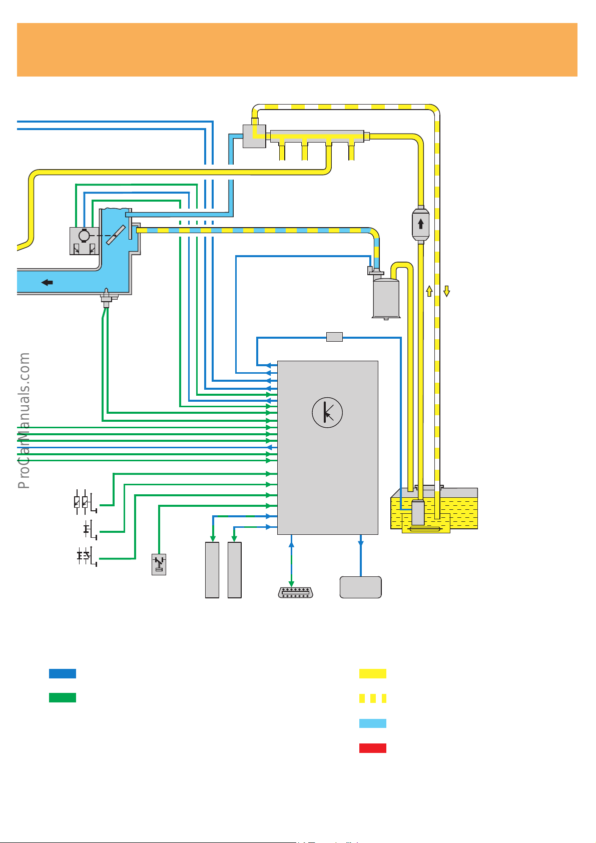
System Overview
S
Simos 3PB engine management
The Simos engine management system
controls the fuel injection and the ignition in
line with the current engine load. The engine
load is detected by the engine speed sensor
and by the intake manifold pressure sensor.
The control unit uses this information to
calculate the ignition timing point and period
of injection, taking into account the correction
factors.
The correction factors are:
– Cylinder-selective knock control
– Lambda control
– Idle speed control
– Activated charcoal filter control
G39
Z19
N152
P/Q
N30
The position of the throttle flap is controlled
electrically.
Additional signals regarding the clutch pedal
and brake pedal position and load supplied by
the power steering pump, are integrated in the
control system of the engine management.
The engine control unit is designed to operate
with CAN data transfer.
Legend
F/F47 Brake light/brake pedal switch
F36 Clutch pedal switch
F88 Power steering pressure switch
G6 Fuel pump
G39 Lambda sensor
G28 Engine speed sensor
G61 Knock sensor
G62 Coolant temperature sensor
G71 Intake manifold pressure sensor
G72 Intake manifold temperature sensor
G79 Accelerator pedal position sensor
G163 Camshaft position sensor
G185 Sensor 2 for accelerator pedal position
G186 Throttle flap drive
G187 Angle sensor 1 for throttle flap drive
G188 Angle sensor 2 for throttle flap drive
J17 Fuel pump relay
J338 Throttle flap control unit
J361 Simos 3PB control unit
K132 Electronic throttle fault lamp
N30 Injector
N80 Activated charcoal filter solenoid valve
N152 Ignition transformer
P Spark plug connector
Q Spark plugs
Z19 Lambda probe heater
G163
Simos 3PB
G62
G61
G28
3rd generation with
electronic throttle and
CAN BUS
iemens e ngine c ontrol
10
Page 10
11
J338
G186
G187
G188
M
G71 G72
B
C
A
N80
D
J17
J361
G79
G185
F36
F
F47
= Output signal
= Input signal
-
+
F88
E
CAN - BUS
CAN - BUS
A = Fuel filter
B = Fuel pressure regulator
C = Fuel rail
D = Activated charcoal filter
E = Diagnostic connection
SIMOS 3PB
G6
EPC K132
SP27_13
= Fuel feed
= Fuel return
= Intake air
= Exhaust
Page 11

System Overview
The processor-based Simos 3PB engine
management system is matched to the
requirements of the electronic throttle.
Sensors
Engine speed sensor G28
Camshaft position sensor G 163
Intake manifold pressure sensor
G71 and
Intake manifold temperature sensor
G72
Throttle flap control unit J338
(electronic throttle positioner)
Angle sensors for throttle flap
drive G187 and G188
New or additional components compared to
the familiar Simos 2P system are outlined in
colour.
Sensors for accelerator pedal position
G79 and G185
Coolant temperature sensor G62
Lambda sensor G39
Knock sensor G61
Power steering pressure switch F88
Clutch pedal switch F36
Brake light switch F and
Brake pedal switch F47
*
CAN - BUS H
CAN - BUS L
Air conditioning (pressure sensor)
AC compressor (AC switch operation)
AC compressor
Road speed signal
12
* in preparation
Page 12

Simos 3PB control unit
J361
Actuators
Fuel pump relay J17
Fuel pump G6
W
4
3
1/min x 1000
5
2
6
1
7
120
100
140
km/h
80
160
60
180
40
200
20
220
J218
240
Combination
processor in dash
panel insert/
immobiliser
K
Injectors N30 … N33
Ignition transformer (4x)
N152 (ignition block)
Throttle flap control unit J338
Throttle flap drive G186
Lambda probe heater Z19
Diagnostic connection
SP27_09
Activated charcoal filter solenoid
valve N80
Electric throttle control fault
EPC
lamp K132
Vehicle speed signal (dash panel insert)
AC compressor
Fuel consumption signal (dash panel insert)
13
Page 13

System Overview
Engine speed sensor G28
Installation point
The sensor is installed at the gearbox above
the flywheel.
Use of signal
The engine speed sensor is an inductive
sensor.
It detects the engine speed and the exact
angular position of the crankshaft.
Operation and design
Sensor segments are integrated around the
circumference of the flywheel, in addition to
the starter ring gear. The circumference is
divided into 60 segments for this purpose and
features a gap of two segments.
When the segments rotate past the sensor, the
magnetic field of the sensor is altered. This
change in the magnetic field induces an
electric voltage in the coil winding of the
sensor. Its frequency changes in line with
engine speed. The frequency is a measure of
engine speed. The electric voltage is passed to
the control unit.
The position of the crankshaft is fixed by
means of the segment gap. Together with the
camshaft position sensor, the exact position
of the engine mechanical components, i.e. the
ignition TDC of cylinder 1, is detected.
This serves as a basis for defining the
injection and ignition timing points.
Flywheel with
sensor segments
Starter ring gear
Engine speed
sensor
SP27_03
Segment gap
Electric circuit
Substitute function and self-diagnosis
The signal supplied by the engine speed
sensor is checked for plausibility together with
the signal supplied by the camshaft position
sensor. If the Simos control unit does not
detect any signal from the engine speed
sensor, the engine stops. It can, however, be
started again. In this case, it operates in the
emergency running programme and uses
signals supplied by the camshaft position
sensor G163.
Self-diagnosis detects:
“G28 no signal” and “G28 implausible
signal”.
14
SP27_10
Page 14

Camshaft positions sensor G163
The camshaft position sensor operates on the
Hall sensor principle. It is located next to the
oil filter at the level of the camshaft.
Use of signal
It is essential to accurately define cylinder 1
for the cylinder-selective knock control and
the sequential fuel injection.
Ignition TDC of cylinder 1 is detected
(synchronisation of cylinder 1) by means of
the signal supplied by the camshaft position
sensor together with the signal supplied by
the engine speed sensor G28 (engine speed
sensor and reference mark).
Once both signals have been received
simultaneously, initial fuel injection and
ignition is then activated.
Operation and design
The “camshaft pulse generation” is effected
directly by the orifice rotor, which is part of
the camshaft. it has a 180° window and a
continuous segment of 180°.
The 180° segment passes through the
magnetic field of the sensor and intersects the
lines of magnetic force.
As it passes, it generates a voltage.
In contrast, the 180° window does not affect
the magnetic field.
The Simos control unit processes this signal
sequence.
Orifice rotor
180° window
Camshaft
SP27_11
Camshaft position sensor G163
Electric circuit
Substitute function and self-diagnosis
In the event that the camshaft position sensor
fails, the engine control unit switches off the
knock control and the ignition angle is
retarded.
The engine continues running using as a
substitute the signal supplied by the engine
speed sensor G28.
Self-diagnosis detects:
“G40 implausible signal” and “G40 signal too
small”.
J361
89 105 111
+
G163
-
SP27_12
15
Page 15

System Overview
Simos 3PB system function
In the diagram below, we see the signal
pattern of the engine speed sensor and the
camshaft sensor.
The signal patterns can also be rendered
visible with the oscilloscope function of
VAS 5051.
They illustrate how the signals are processed
in the Simos control unit in order to determine
the position of the engine mechanical
components for defining the fuel injection and
ignition timing points.
TDC TDC TDC TDC TDC
Firing order
Tooth No.
61 74 88 104 118 1 14 28 44 58 61 74
58
Cyl. 4 Cyl. 2 Cyl. 1 Cyl. 3 Cyl. 4
Note:
2 crankshaft revolutions with 2 x
(60 – 2) teeth (teeth are numbered
consecutively up to 120) and
1 camshaft revolution with
1 x 180° window, form an analysis
cycle.
The top dead centre is at the same
time the ignition top dead centre.
1st falling tooth edge after gap is at 78° crank
angle before ignition TDC of cylinder 1 or 4
Crankshaft signal from
sensor G28
Camshaft signal from
camshaft position sensor
G163
Effects in the event of signal failure
refer to pages 14 and 15
2nd crankshaft revolution 1st crankshaft revolution
o
-window
180
Falling edge located at tooth 88, i.e.
14 teeth after ignition TDC of cylinder 4
1 camshaft revolution
SP27_16
Rising edge is located at tooth 28 after
gap, i.e. 14 teeth (84°) after ignition TDC
of cylinder 1
16
Page 16

Fuel injection
Intake manifold pressure
and intake manifold
temperature sensor
Throttle flap control unit
Fuel rail
To air filter
Pressure regulator
Injector
Intake module
Intake module
The intake module houses the throttle flap
control unit and the fuel rail together with the
injectors and the pressure regulator. The
intake manifold pressure and intake manifold
temperature sensor is located at the side of
the intake manifold.
Fuel injection
Each cylinder features an electro-magnetic
injection valve which is positioned in the
intake manifold upstream of the inlet valve.
The valves are supplied with fuel by the fuel
pump and actuated through earth by the
engine control unit.
The fuel injected gathers first of all in the
intake port and is inducted into the
combustion chamber together with the air
when the inlet valve opens.
SP27_38
The injectors are operated in line with the
firing order of 1 – 3 – 4 – 2 (sequential fuel
injection).
The commencement of injection angle is
always related to the ignition TDC of the
corresponding cylinder.
The control unit takes into account the
following correction factors for determining
the opening time of the injectors:
– Cylinder-selective knock control
– Lambda control
– Idle speed control
– Activated charcoal filter control
17
Page 17

Electronic Throttle Function
Electrically operated throttle flap
Pedal value sensor
Sensors for accelerator pedal
position G79 and G185
* Central Processor Unit
Engine control unit
Input signals Output signals
CPU*
Safety module
New!
Throttle flap control
unit J338
Throttle flap
drive G186
SP27_26
Angle sensors for
throttle flap drive G187
and G188
There is no mechanical and no direct electrical
link in the Simos 3PB engine management
system between accelerator pedal and throttle
flap. These are replaced by an electronic
control.
The system includes:
– Pedal value sensor (at accelerator pedal)
– Engine control unit
– Throttle flap control unit
The driver input at the accelerator pedal is
detected by the pedal value sensor and
transmitted to the engine control unit.
The engine control unit alters the position of
the throttle flap by means of a dc motor.
The position of the throttle flap is, in turn,
continuously signalled back to the engine
control unit.
Advantages
In addition to the intake air control, functions
such as
– idle speed control
– vehicle speed control
– engine speed limit
are achieved in a simple and convenient way.
The throttle flap can be opened irrespective of
the position of the accelerator pedal.
The electronic throttle makes it possible to
achieve significantly improved emission and
fuel consumption levels in certain engine load
states.
A wide range of measures in terms of hardware and software (duplicate sensors, selfmonitoring processor structure) are intended
to ensure high operational reliability.
18
Page 18

Accelerator pedal with pedal value
sensor (sensors for accelerator
position G79 and G185)
Accelerator pedal and pedal value sensor
form a single unit and are also known as the
accelerator pedal module.
The mechanism is housed in the module
housing.
The sensors – accelerator pedal position
sensor G79 and G185 – are located in the
housing.
Two sensors operating independently, are
used in order to provide reliable operation of
the electronic throttle.
The pedal value sensor operates as a slidingcontact potentiometer.
A stabilised voltage of 5 V is supplied by the
engine control unit to each potentiometer for
detecting the position of the accelerator pedal
at the sliding-contact potentiometer.
The signal regarding the position of the
accelerator pedal is passed as a voltage signal
to the engine control unit.
Module housing with
pedal value sensor
Accelerator pedal
SP27_27
The characteristic curves of the two sensors
differ in pattern (see chart).
The engine control unit monitors the function
and plausibility of the two sensors.
If one sensor fails, the other acts as a
substitute.
The entire module is pre-set.
It is replaced as a complete unit in the event of
repairs.
SP27_28
Sensor for accelerator pedal position G79 and
sensor 2 for accelerator pedal position G185 in
module housing
kΩ
2,0
1,6
1,2
0 % 100 %
Accelerator pedal travel
Idle speed Full throttle
G185
G79
SP27_29
19
Page 19

Electronic Throttle Function
Self-diagnosis/emergency running
to accelerator pedal
If a fault occurs at the pedal value sensor or in
the wiring, two emergency running
programmes are available, depending on the
type of fault.
Failure of one sensor for accelerator pedal
position
– Electronic throttle fault lamp K132 comes
on.
– Fault is stored.
– Engine continues running normally.
– The customer should take the car to a
service workshop.
Requirement for emergency running
programme:
Idle throttle position must be detected
once by the operating sensor.
– The signal of the brake light switch F
and brake pedal switch F47 is used for
detecting idle speed.
– Convenience features such as cruise
control system are disabled.
Emergency running programme 1
Failure of both sensors for accelerator pedal
position = not possible to detect driver input
– Electronic throttle fault lamp K132 comes
on.
– Fault is stored.
– Engine runs at increased speed of approx.
1500 rpm.
– Customer should take car to a service
workshop.
20
Emergency running programme 2
Page 20

Throttle flap control unit J338 with
throttle flap drive G186, angle
sensor 1 G187 and 2 G188 for
throttle flap drive
Throttle flap housing
with throttle flap
Throttle flap drive G186 (electric
throttle operation)
Angle sensors for throttle flap
drive G187 and G188
The throttle flap control unit consists of
– throttle flap housing with throttle flap
– throttle flap drive G186
– angle sensors for throttle flap drive G187
and G188
The throttle flap is moved by the throttle flap
drive (dc motor). It is operated by the engine
control unit and in this way regulates the air
flow required for producing the torque. The
feedback signal regarding the current throttle
flap angle is supplied by two angle sensors
(potentiometers) to the engine control unit.
These sensors are attached to the throttle flap
shaft.
The throttle flap is limited in the top and
bottom position by a mechanical stop.
Two angle sensors are used for safety
reasons. Their resistance characteristic curves
are inversed (see chart).
If one angle sensor fails, the engine
control unit activates an emergency running
programme and the operation of the electronic throttle is maintained. If the drive is deenergized, the throttle flap is moved into an
emergency running position by the force of a
spring.
Spiral spring
Stop at housing
Note:
The throttle flap control unit must not
be opened.
The angle sensors must be “learned”
in a basic position.
Please refer to the information in the
Workshop Manual.
kΩ
1,5
1,0
0,5
0 % 100 %
Throttle flap opening
SP27_05
G188
G187
SP27_36
21
Page 21

Electronic Throttle Function
Function position of the throttle
flap control unit
The engine control unit detects four important
function positions.
Lower mechanical stop
Throttle flap is fully closed. This position is
required for adapting the angle sensors.
Stop at housing
Throttle flap is
word linearly
Rotary disc with
stop cam
SP27_32
Lower electrical stop
Is defined by the engine control unit. Is
positioned only slightly above the bottom
mechanical stop.
In operation, the maximum closed position of
the throttle flap is fixed by this stop.
This prevents the throttle flap “working into”
the housing.
Emergency running position
Position of throttle flap in the de-energized
state. Adequate air flow is assured in the
event of the electronic throttle failing. Fast
engine idling speed of approx. 1500 rpm.
Car can continue to be driven with severe
restrictions.
M
SP27_33
M
SP27_34
Upper mechanical stop
Full throttle position of throttle flap.
Of little significance in operational terms.
Full throttle is set by the “upper electrical
stop”, which is defined by the engine control
unit.
22
M
SP27_35
Page 22

Basic setting (adaptation) of
throttle flap control unit
The angle sensors of the throttle flap drive
G187 and G188 have to be learned to enable
the exact angle position of the throttle flap to
be detected.
Learning is done by initiating function 04 –
Basic setting.
This can be performed using the vehicle
system tester V.A.G 1552, the fault reader
V.A.G 1551 or with the vehicle diagnosis
measurement and information system
VAS 5051.
Adaptation of the throttle flap position is
performed when function 04 Basic setting is
activated with “display group number 60”.
1
2
3
4
5
6
7
8
9
C
O
HELP
Q
V.A.G.
1552
When this is done, the throttle flap positioner
is moved out of the “emergency running
position” (de-energized state) to the MIN and
MAX positions. The values of the potentiometer voltages which are measured in these
positions, are then stored in the control unit.
Adaptation conditions!
“Engine not running, ignition on”.
If an attempt is made to activate the throttle
flap adaptation if the vehicle is not in this state
or if throttle flap adaptation is prevented for
other reasons (e.g. throttle flap positioner
opened mechanically, diagnostic fault of
positioning motor, etc.), this is displayed with
a text at the vehicle system tester.
Measured value blocks for throttle flap
actuation can be retrieved with function 08 –
Reading measured value blocks.
202_CZ_002
SP17-29
Note:
Pay attention to the adaptation
conditions!
“Function is unknown or cannot be
carried out at the moment.”
23
Page 23

Electronic Throttle Function
Self-diagnosis/emergency running
to throttle flap control unit
If a fault occurs at the throttle flap control
unit or in the wiring, emergency running
programmes are available, depending on the
type of fault.
Failure of one angle sensor for throttle flap
drive or implausible signal
– System activations which increase engine
torque (e.g. cruise control system, engine
braking torque control) are suppressed.
– Electronic throttle fault lamp K132 comes
on.
Failure or control fault of throttle flap drive
– The throttle flap drive is switched off. The
throttle flap moves into the emergency
running position. This is noticeable from a
sharp drop in engine output and fast
engine idling speed.
– Electronic throttle fault lamp K132 comes
on.
Note:
A faulty throttle flap control unit is
not repaired. If a fault occurs at the
throttle flap positioner or at the angle
sensors, the complete control unit
must be replaced.
Emergency running programme 1
Requirement
One angle sensor is operating properly.
Plausible air mass flow is detected (intake
manifold pressure sensor G71 and intake
manifold temperature sensor G72 operating
normally).
Emergency running programme 2
Requirement
The emergency running programme is only
activated if the emergency running position is
detected by both angle sensors of the throttle
flap drive.
No clear detection of throttle flap position
possible or if it is not certain that throttle flap
is not in the emergency running position
– The throttle flap drive is switched off. The
throttle flap moves into the emergency
running position, if possible. This is
noticeable from fast engine idling speed.
– Engine speed is limited to approx.
1500 rpm by switching off fuel injection.
– Electronic throttle fault lamp K132 comes
on.
24
Emergency running programme 3
Page 24

Electronic throttle fault lamp K132
4
3
1/min x 1000
2
1
When the ignition is switched on, the EPC
fault lamp comes on in the indicator lamp
panel of the dash panel insert. It must go out
again after 3 seconds (operational test of
lamp).
The fault lamp is operated directly by the
engine control unit J361 through an earth
voltage to the combination processor in the
dash panel insert J218.
If a fault occurs in the electronic throttle
system, this is detected by the self-diagnosis
and indicated by the separate EPC fault lamp.
In this case, the fault lamp comes on and
remains on.
At the same time, an entry is stored in the
fault memory.
120
100
5
6
7
80
60
40
20
km/h
140
160
180
200
220
240
SP27_08
Note:
EPC means
Electronic Power Control (electronic
throttle)
Electric circuit
J218
If a fault occurs in the electronic throttle
system, a matching emergency running
programme is activated (refer also to sensors
for accelerator pedal position and throttle flap
control unit).
73
J361
SP27_60
25
Page 25

Sensors
Brake light switch F and brake pedal
switch F47
Task
The information “brake operated” is used for
controlling two systems:
– Backup interrogation of electronic
throttle function (idle speed detection in
emergency running mode of pedal value
sensor)
– Operation of cruise control system (on
models fitted with this).
(The main function is switching on the brake
lights; on models fitted with ABS, this signal is
used for informing the ABS control unit.)
Function
The brake light switch F and the brake pedal
switch F47 are combined to form a single
component. For safety reasons, both act as
information senders for “brake operated”. The
combination switch has four connections.
The brake light switch F is open in the off
position and is supplied with voltage through
terminal 30.
It is the switch for operating the brake lights
and acts as an additional information input for
the Simos control unit.
Brake light switch F and
Brake pedal switch F47
Electric circuit
+
30
+
SP26_40
15
The brake pedal switch F47 is closed in the off
position and is supplied with voltage through
terminal 15.
Its only purpose is to act as an information
input for the Simos control unit.
Self-diagnosis
Both switches are checked mutually for
plausibility by the self-diagnosis.
Note:
If an accelerator pedal position sensor
fails, the electronic throttle function
uses the signal from the brake light
switch or brake pedal switch to detect
idle speed.
26
F
53
F47
63
J361
SP27_48
Page 26
Clutch pedal switch F36
Task
The information “clutch operated” is used for
controlling two systems:
– On models fitted with a cruise control
system, the function of the cruise control
system is switched off.
– The load change functions are deactivated
during a gearshift. The load change
function is controlled by influencing the
ignition angle and by the closing rate of
the throttle flap.
Function
Like the brake pedal switch, the clutch pedal
switch is closed in the off position.
It is supplied with voltage through terminal 15.
cal resistance.
When the clutch pedal is operated, the information passes directly to the Simos control
unit.
Substitute function and self-diagnosis
The clutch pedal switch is not detected by the
self-diagnosis.
Consequently, no substitute functions are
derived. If no signal is received, the function is
not activated.
Electric circuit
+
15
SP23_32
Note:
In the event of an incorrect setting,
electrical malfunction or incorrect
operation (driver leaves foot on clutch
pedal), this can result in operating
problems (load change jolts, sudden
increases in engine speed).
F36
65
J361
SP27_49
27
Page 27

Sensors
Power steering pressure switch F88
All OCTAVIA models are fitted as standard
with a power-assisted steering.
The hydraulic pump of the power steering,
which is driven by the engine through the
ribbed V-belt, increases the load on the engine
when the steering is turned to full lock; when
the engine is idling, this may result in a sharp
drop in engine revs.
The Simos 3PB system control compensates
for this situation and additionally processes a
signal which supplies information regarding
the additional load resulting from the power
steering.
The engine control unit detects the additional
engine load at an early stage by means of the
signal supplied by the power steering
pressure switch F88 and controls the idle
speed accordingly.
Power steering
hydraulic pump
SP27_46
Power steering pressure
switch F88
Operating principle
The power steering pressure switch is located
at the hydraulic pump.
The pressure switch is open at a pressure of
< 0.28 MPa (28 bar).
If the pressure rises, the switch is closed at
0.4 MPa (40 bar).
The signal passes to the Simos engine control
unit.
The engine control unit in turn operates the
throttle flap drive G186 which opens the
throttle flap by a particular angle.
Idle speed is thus stabilised to compensate for
the increased load of the hydraulic pump.
Self-diagnosis
Self-diagnosis is performed in the functions
02 - Interrogating fault memory
08 - Reading measured value block
Electric circuit
F88
30 47
J361
121 119
+
-
M
G186
SP27_47
28
Page 28

Lambda sensor G39
A new generation of lambda sensors is used
on the 1.4-ltr./44 kW engine.
The planar (= flat) lambda sensor is a further
development of familiar finger-shaped
lambda sensor and has a step characteristic at
λ = 1.
Advantage
– Short heating-up time and thus improved
emission levels in the warming-up phase
– Reduced heating capacity demand
– More stable control characteristic
Rapid response of the lambda sensor is
essential in order to be able to ensure efficient
emission control. This necessitates the
lambda sensor achieving its operating
temperature in the shortest possible time.
This is made possible by the planar (= flat)
design of the sensor.
The sensor heater is integrated in the sensor
element. The operating temperature is
reached more rapidly with a reduced heating
capacity.
Particular feature
The sensor heater generates the necessary
minimum temperature of 350°C at an exhaust
temperature as low as 150°C.
The lambda control reaches operational
readiness about 10 seconds after engine start.
Sensor element
with heater
Double protective
tube
Sensor section
Sensor heater
+
New!
Insulating layer
S243
10A
SP198_37
Exhaust
Porous protective layer
ceramic
ZrO
2
Reference air
The sensor element consists of circon dioxide
).
(ZrO
2
A porous, ceramic protective layer is applied
to the sensor element. This prevents any
damage occurring as a result of residues in
the exhaust gases.
High operational life and reliable achievement
of the high operational demands are assured.
Substitute function
Open-loop control mode by means of map.
Z19
G39
λ
04 31 14
J361
SP27_20
29
Page 29

Sensors
Intake manifold pressure sensor
G71 and intake manifold
temperature sensor G72
The sensor is located at the middle part of the
intake manifold directly downstream of the air
inlet. Pressure sensor and air temperature
sensor thus are in direct contact with the air
inducted into the intake manifold.
Use of signal
Intake manifold pressure and intake manifold
temperature are transmitted to the engine
control unit. They are required in order to
calculate the quantity of air inducted by the
engine. This information is used to calculate
the injection time required as well as the
ignition timing point.
Substitute function
If the signals are not received, the engine
control unit uses the signal of the throttle
valve position and of the engine speed for
calculating the injection time as well as the
ignition timing point.
The engine is operated in accordance with an
emergency running map!
If the signal from the intake manifold
temperature sensor is not received,
a substitute value based on the coolant
temperature is then used.
Intake manifold pressure and
intake manifold temperature
sensor
Intake
manifold
SP27_39
Electric circuit
J361
96 9395 107
Self-diagnosis
Self-diagnosis checks both input signals.
The following faults can be detected:
– Short circuit to earth
– Short circuit to positive voltage and
reference voltage
– Open circuit
30
G71
G71 Intake manifold pressure sensor
G72 Intake manifold temperature sensor
J361 Simos control unit
G72
SP27_40
Page 30

Function Diagram
Legend to function diagram of page 32
The function diagram represents a simplified
current flow diagram.
It shows all the connections of the Simos 3PB
engine management system for the 1.4-ltr./
44 kW engine.
Additional signals
A Engine speed
B Fuel consumption signal
C Diagnostic cable
D Vehicle speed signal (in)
E AC standby (in)
F AC compressor on/off
G AC pressure signal
H Signal to electronic throttle fault
lamp
Colour coding/Legend
= Input signal
= Output signal
= Battery positive
Components
A Battery
F Brake light switch
F36 Clutch pedal switch
F47 Brake pedal switch
F88 Power steering pressure switch
G6 Fuel pump
G28 Engine speed sensor
G39 Lambda sensor
G61 Knock sensor
G62 Coolant temperature sensor
G71 Intake manifold pressure sensor
G72 Intake manifold temperature
sensor
G79 Accelerator pedal position sensor
G163 Camshaft position sensor
G185 Sensor -2- for accelerator pedal
position
G186 Throttle flap drive (electric throttle
operation)
G187 Angle sensor -1- for throttle flap
drive (electric throttle operation)
G188 Angle sensor -2- for throttle flap
drive (electric throttle operation)
J17 Fuel pump relay
J361 Simos control unit
J338 Throttle flap control unit
M Brake light
N152 Ignition transformer
N30...33 Injectors
N80 Activated charcoal filter system
solenoid valve
P Spark plug connector
Q Spark plugs
S Fuse
Z19 Lambda probe heater
= Earth
= Bidirectional
31
Page 31

Function Diagram
Simos 3PB
30
15
86 30
J17
4
85 87
S132
50A
A
S228
15A
+
-
S232
10A
Z19
S243
10A
G39
S134
10A
F36
N80
λ
N30
80 88 87 85 86 04 31 14 61 65
91 90 97 92 121 119 89 105 111 20 21 41
N31
N32
N33
+
-
+
M
-
+
-
S113
10A
14
J361
32
31
M
G6
G187
G188 G186
J338
G163
CAN - BUS
CAN - BUS
Page 32

30
15
+
30
M
F/F47
63 53 18 51 50 19 64 45 22 75 17 9 28 76 29 73 62 03
G79/G185
A
C D E H
F
GC
106 98 99 109 101 100 30 47 96 9395 107 104 83 01 02 113 112
+
-
S10
10A
S120
15A
G28
in out
G61
F88
G71
G72
G62
I IV III
II
N152
Q
P
31
SP27_02
33
Page 33

Technical Data
Technical features
New!
SP27_14
The 1.4-ltr./44 kW engine is fitted to the
ŠKODA OCTAVIA in combination with the
manual gearbox M5 002.
The manual gearbox is based on the triedand-tested gearbox 14 SK.
It is matched to the engine characteristics and
to the pendulum mounting in the OCTAVIA.
Transmission code letter: DTQ
– 5-speed manual gearbox.
– Light-alloy two-section housing, with
compact gearbox end cover.
– Gearbox end cover designed as bearing
bracket for mounting the gearbox bearing
for the pendulum mounting of the engine
block.
– Connection of pendulum support with a
bolt on the underside of the gearbox
housing.
– 5 all-synchromesh forward gears, non-
synchromesh reverse gear.
– Common oil supply for gearbox and final
drive.
– Final drive with flange shafts for attaching
the CV joint shafts.
– Overhead starter.
– Hydraulic clutch mechanism.
– External shift designed as cable shift.
34
Page 34

Block diagram of gearbox
– Helical gears are used for the gearing of
the sliding and fixed forward speed gears.
– The sliding gears (loose gears) of 1st to 4th
speed run in friction bearings while 5th
speed is mounted in needle bearings.
– The gears are shifted by means of shift
forks.
– Mechanical tapping of engine speed for the
speedometer with drive gear and pinion at
final drive. Vehicle speed signal to electric
speedometer by means of pulse generator.
SP27_15
Gear reduction i =
Teeth of driven gear z
Teeth of driving gear z
z
2
z
1
2
1
i
1st gear 45 13 3.462
2nd gear 45 23 1.957
3rd gear 38 28 1.357
4th gear 40 38 1.053
5th gear 36 42 0.857
Reverse 29
38
13
29
2.923
Final drive 72 17 4.235
Speedometer 16 27 0.593
35
Page 35

Engine/Gearbox Mounting
Complete engine/gearbox mounting
Engine mount
Gearbox mount
You will be familiar with the principle of the
engine/gearbox mounting in the OCTAVIA
(pendulum mounting) from Self Study Programme 15.
Appropriate adaptations have been made to
the engine and gearbox for the design of the
engine mount, the gearbox mount and the
pendulum support.
Engine mount
The combination of housing for coolant pump
and supporting arm for engine mount has
been retained.
Pendulum support
SP15_50
Recess for engine
mount
Housing of coolant
pump
The housing of the coolant pump has been
matched to the conditions of increased
mechanical stress and designed for directly
accommodating the engine mount.
36
SP27_25
Page 36

Gearbox mount
The rear gearbox end cover is designed at the
same time as a bracket for accommodating
the gearbox mount.
Bracket for gearbox
mount
SP27_23
Rear gearbox end
cover
Pendulum support
As on gearboxes 02K and 02J, the pendulum
support is attached directly to the bottom of
the gearbox with two bolts.
The gearbox housing is strengthened locally
at the point at which the pendulum support is
attached at the front.
The light-alloy housing is reinforced by a steel
insert at the bolt attachment point.
SP27_24
Pendulum support
Bolt connection
37
Page 37

Clutch Mechanism
Slave cylinder
New!
Plunger
Clutch release lever
Release bearing
Guide sleeve
Input shaft
The clutch mechanism is matched to the
installation conditions in the OCTAVIA and is
operated hydraulically. The slave cylinder is
located at the clutch housing.
It presses on the clutch release lever by means
of a plunger.
The clutch release lever is supported by
means of a ball head at the clutch housing.
The release bearing is mounted on a guide
sleeve which is bolted to the clutch housing.
The clutch is operated through the release
bearing.
Clutch housing
Ball stud
SP27_37
The clutch release lever is guided at the
release bearing, which is secured by the guide
sleeve to prevent it slipping out.
Consequently, it is not necessary to carry out
any additional securing work when removing
the gearbox.
Note:
After removal and installation work at
clutch mechanism, the system should
be bled with a brake filling and
bleeding appliance.
38
Page 38

External Shift
Two cables are used to transmit the shift
movements (selecting and shifting). The
operating principle is similar to that of manual
gearbox 02J.
The shift pattern and the position of the
reverse gear are the same as on the shift
mechanism familiar from the FELICIA.
The shift movements of the gearshift lever are
transmitted to the inner shift mechanism of
the gearbox by means of an outer shift relay.
Outer shift relay
Balancing weight
A balancing weight on the shift relay lever is
designed to absorb vibrations and as a shift
force assist.
The two cables are supported by a support
bracket.
The support bracket is guided at the front at
the gearbox and at the rear at the steering
gear in Silent bushes.
Shift relay lever
Support bracket
55
33
R
11
Shift cable
44
22
SP27_51
Shifting and selecting at gearshift lever
Selector cable
If the gearshift lever is moved when selecting,
the pivot point is located in the selector
housing. The gearshift lever guide is linked for
this purpose to the selector housing. The latter
is mounted in the shift housing.
The ball head attached to the bottom of the
selector housing performs an opposite movement. It is surrounded by the selector angle.
This converts the movement of the gearshift
lever during selection into a pull/push movement.
If the gearshift lever is moved in the direction
of a gear (shifting), the pivot point is located in
the gearshift lever guide. The shift cable
transmits the forward/reverse movement
through the relay mechanism to the shift shaft
of the gearbox.
Shift lever
guide
Pivot point
when shifting
Shift housing
SP27_50
Selector housing
Pivot point
when selecting
Selector angle
SP27_52
39
Page 39

External Shift
Selection operation
The selector cable is connected to the selector
angle lever. This absorbs the pull/push movement of the selector cable.
The selector movement is transmitted down
through the selector rod and through the gearbox shift lever to the shift shaft of the gearbox.
Gearbox shift lever and shift shaft are bolted
together.
The linear movement coming from the
selector cable is thus converted into the
circular selector movement of the shift shaft of
the gearbox.
Connection of
selector cable
Selector
angle lever
Selector rod
Shift operation
The shift cable is connected at the shift
intermediate lever.
This absorbs the forward/backward movement of the shift cable and transmits it
through the shift coupling rod to the shift
relay lever.
The shift relay lever has a fixed pivot point
and at the bottom runs into the gearbox shift
lever by means of a ball head.
During a gearshift, the linear movement of the
shift cable which is initiated at the top is transmitted linearly, as a result of the double
reversal, to the shift shaft of the gearbox.
Gearbox shift lever
Connection of
shift cable
Shift relay
lever
Pivot point
SP27_53
Shift shaft of gearbox
Shift intermediate lever
Shift coupling rod
The ball head of the shift relay lever compensates for different angle positions, caused by
the selector movements.
(Note: Balancing weight not illustrated)
40
Gearbox shift lever
SP27_54
Shift shaft of gearbox
Page 40

Adjusting outer shift
The components of the outer shift mechanism
have to be adjusted relative to the inner gearbox shift mechanism to ensure smooth and
proper gearshifts.
Gearshift lever
In Neutral, the gearshift lever should be in
position x. In this position, the gearshift lever
is angled back 3° and to the right 4°. This
position is fixed by means of a gauge.
The gearshift lever and gearbox are in Neutral
in the gate of 3rd/4th gear for this step.
Selector cable
The selector cable should not have any play in
the fixed position. A slot is provided for this
purpose at the gearbox shift lever to enable
the selector rod to be set free of play.
x
SP27_57
Selector rod
Shift cable
The shift cable is set at the shift intermediate
lever with a gear engaged (e.g. 1st gear
engaged manually, gearshift lever set to
1st gear position).
A slot is provided for this setting.
Note:
Please refer to the Workshop Manual
OCTAVIA, 5-Speed Manual Gearbox
002 for the exact setting procedure.
After completing the setting, once
again shift through all gears. Pay
particular attention to the reverse
gear lock.
Setting selector cable at
gearbox shift lever
SP27_55
Setting shift cable at shift
intermediate lever
SP27_56
41
Page 41

Final Drive/Speedometer Drive
Inner CV ball joint
Outer CV ball joint
Flexible joint
Connection of drive shafts
All the manual gearboxes fitted to the
OCTAVIA have drive shafts which feature
outer and inner constant-velocity ball joints.
The flange shafts of the gearbox have been
matched to these requirements.
Flange shaft
SP27_19
New!
Differential
Both flange shafts are inserted into the
differential with a spline section.
A circlip holds the flange shaft in position to
prevent it dropping out when the gearbox is
removed.
Speedometer drive
The vehicle speed signal is supplied electromechanically by the gearbox to the speedometer.
Mechanical tapping in gearbox (input gear/
pinion).
The vehicle speed sensor G22 is installed at
the gearbox in place of the speedometer shaft.
It is driven by the pinion (in the same way as
automatic gearbox in OCTAVIA).
Engine speed is transmitted not mechanically
with a speedometer shaft, but electrically in
the form of pulses from the sensor to the
combination processor in the dash panel
insert. The pulses are processed there for
displaying the vehicle speed and the distance.
Advantage: greater accuracy and smoother
operation.
Vehicle speed sensor G22
Input gear
SP27_21
Pinion
SP27_62
42
Page 42

Service
Service information
Oil filling
The oil filling is designed for the entire
operating life of the gearbox.
The opening for inspecting oil level is located
at the bottom in the gearbox end cover.
Correct oil level = Oil filling extends up to
the thread of inspection
opening
The screw plug is inserted with sealant.
The oil level is no longer checked in a service
workshop at the opening of the speedometer
drive with the aid of the speedometer pinion.
Note:
Please refer to Workshop Manual
OCTAVIA, 5-Speed Manual Gearbox
002 for the quantity and specification
of the oil.
New!
Screw plug for inspecting
oil level
SP27_22
Oil filling
Bleeder plug
Bleeding gearbox and topping up gearbox oil
The bleeder plug is located above a labyrinth
which is cast into the top of the gearbox
housing.
It is also possible to top up the oil, if
necessary, through the bleeder hole.
Magnet for metal abrasion
A magnet for collecting metallic abrasion is
now provided at the lowest point of the gearbox housing in a recess.
Bleeder hole
Gearbox
housing
SP27_30
SP27_31
HousingMagnet
43
 Loading...