

Self Study Program 21 – The automatic gearbox 01M in the OCTAVIA embodies matured engineering in the automatic- shift gearbox
SKODA Self Study Program 21 – The automatic gearbox 01M in the OCTAVIA embodies matured engineering in the automatic- shift gearbox SSP-21-Automatic-gearbox-01M
Page 1

EVERY SECOND ONE IN THE
WORLD DRIVES AUTOMATIC!
The automatic gearbox 01M in the OCTAVIA embodies matured engineering in the automatic-shift gearbox.
The automatic gearbox offers the choice between the different shift programmes - depending on the driver's accelerator pedal movements and the driving situation. If the
driver adopts a moderate style of driving, the gearbox switches to "Economy", and if
the driver's movements of the accelerator are sharper, it selects "Sport".
When climbing or descending hills the shift points are automatically selected as a function of the position of the accelerator pedal and the speed of the vehicle.
Thanks to a sophisticated electric-hydraulic control the automatic gearbox combines
performance, economy and driving comfort to offer a convincing automatic driving sensation.
Comprehensive self-diagnosis monitors the electrical/electronic control and ensures
that any irregularities which occur are rapidly detected.
SP21-30
The Self Study Programme is intended to help you acquire the appropriate knowledge
regarding components, design and operation of the automatic gearbox.
2
Page 2

Service Service Service ServiceService
xxxxxxxxxxxxxxxx
OCTAVIA
XXXXXXXXXXXXX
XXXXXXXXXXXXXXX
XXXXXXXX
xxxxxxxxxxxxxxxx
OCTAVIA
XXXXXXXXXXXXX
XXXXXXXXXXXXXXX
XXXXXXXX
xxxxxxxxxxxxxxxx
OCTAVIA
XXXXXXXXXXXXX
XXXXXXXXXXXXXXX
XXXXXXXX
xxxxxxxxxxxxxxxx
OCTAVIA
XXXXXXXXXXXXX
XXXXXXXXXXXXXXX
XXXXXXXX
xxxxxxxxxxxxxxxx
OCTAVIA
XXXXXXXXXXXXX
XXXXXXXXXXXXXXX
XXXXXXXX
Contents
Introduction 4
The automatic gearbox 01M 4
Selector lever positions 8
Mechanical Components 10
Planetary gear system 10
Planet gear set 12
Final drive/Differential 13
ATF Circuit 14
ATF circuit (block diagram) 14
Oil pump (ATF pump) 15
Torque Converter 16
The hydrodynamic torque converter 16
Torque Converter Lock-up Clutch 18
Torque converter lock-up clutch 17
Flow of hydraulic power 19
Flow of mechanical power 19
Operating principle of the lock-up clutch 20
Shift Elements 22
Multi-disc clutches 22
Multi-disc brake 24
Freewheel 25
Power Flow 26
Overview of System 32
Sensors 34
Actuators 43
Subsystems 48
Selector lever lock 48
Park lock 50
Emergency Programme/Emergency Running 51
Self-Diagnosis 52
Function Diagram 54
You can find information on inspection and
maintenance, setting and repair instructions in
the Workshop Manual.
3
Page 3

Introduction
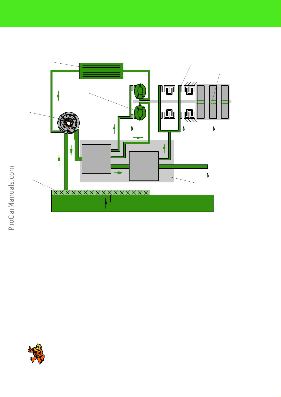
The automatic gearbox 01M
Planetary gear
Oil cooler
(ATF cooler)
Oil pump
(ATF pump)
Intermediate
gear stage
Differential
Torque converter with lock-up
clutch
Flange shaft
SP21-5
4
Page 4

The automatic gearbox 01M has been developed for models with a power range from 55 up to
128 kW.
The gearbox is also transversely mounted relative to the direction of travel to match the installation position of the engine in the OCTAVIA.
The mechanical components of the automatic gearbox operate on the principle of the planetary
gear system.
The gearbox features a hydraulic-electronic control.
The hydraulic shift control unit is positioned below the gearbox in the oil sump.
The electronic control unit (ECU) is installed in the vehicle (in the plenum chamber).
It processes input information and selects a matching shift programme in line with the style of
driving.
The gears are then shifted automatically.
The gearbox and torque converter are matched in their overall ratio to the particular power output of the engine.
The power from the engine is passed by a hydrodynamic torque converter with integrated lockup clutch into the gearbox.
The 4 forward gears and reverse gear are formed by means of a Ravigneaux planetary gear
system.
The power is passed on to the differential and to the flange shafts through an intermediate
gear stage.
Tripod constant velocity joint shafts link the gearbox to the final drive.
A separate cooler is located directly on the gearbox for cooling the automatic transmission fluid
(ATF).
The ATF cooler is integrated in the coolant circuit of the vehicle.
5
Page 5

Introduction
Depending on the ratio required, sun wheels
or the planet carrier in the Ravigneaux planet
gear set are held fixed or driven and the 4 forward gears and reverse gear formed in this
way.
The shift elements required for this are the
clutches K1 to K3,
the brakes B1 and B2 and the freewheel F.
F B1 K3 K1 K2 B2
Ravigneaux planetary gear system
K
SP21-12
Hydraulic shift control unit
(control valve housing)
6
Page 6

The shift elements are assigned as follows
R
1
2
3
4
B1 B2 K1 K2 K3 F K
H
M
H
M
H
M
H
M
K1 = 1st to 3rd gear clutch
K2 = Reverse gear clutch
K3 = 3rd and 4th gear clutch
B1 = Reverse gear brake
B2 = 2nd and 4th gear brake
F = Freewheel
K = Torque converter lock-up clutch
All the gears are shifted hydraulically.
The torque converter lock-up clutch (K) is closed hydraulically at a fixed
engine load and vehicle speed.
It then drives all the forward gears mechanically.
The table below shows you the shift elements which are operated in the individual gears:
X = Clutches, brakes or freewheel
closed
H = Hydraulic
M = Mechanical
SP21-28
7
Page 7

Introduction
Selector lever positions
Starting the engine
The engine can be started only if the selector
lever is in position P or N.
Selector lever lock
The selector lever is locked in the positions P
and N if the ignition is switched on. The lock is
indicated by the warning lamp next to the selector display coming on.
The brake pedal has to be depressed in order to
override the lock.
The purpose of the selector lever lock is to prevent a gear being engaged unintentionally and
the vehicle setting off in an uncontrolled manner.
In other words, it is necessary to depress the
brake pedal and at the same time to press the
selector lever lock button in order to move the
selector lever out of positions P or N.
Touchbutton for selector
lever lock
Indicator lamp for selector lever lock
Selector level
SP21-29
Position/Function
P = Park position
The gearbox output is locked mechanically.
R = Reverse gear range
N = Neutral. No torque is transmitted.
D = Drive position of automatic gearbox.
3 = Automatic shift from 1st to 3rd and 3rd to 1st gear
2 = Automatic shift from 1st to 2nd and 2nd to 1st gear
1 = Car moves off only in 1st gear.
"P" can only be engaged if the vehicle is stationary.
The ignition key can be withdrawn.
Also start position.
Must only be engaged when the vehicle is stationary and engine idling.
Also start position.
Position for normal driving in 1st to 4th gear.
4th gear cannot be engaged. Select this drive position if position D would result in
frequent gear changes in certain driving situations.
Also recommended for lengthy downhill stretches.
3rd and 4th gears cannot be engaged.
Select this drive position when travelling in mountainous regions with lengthy uphill and
downhill stretches.
2nd to 4th gears cannot be engaged.
Recommended for extreme downhill stretches in order to achieve maximum engine
braking effect.
8
Page 8

Push-tow-starting
It is not possible to start the engine by
pushing or tow-starting the car if it is fitted
with an automatic gearbox.
The control pressure required for shifting a
gear is produced by the ATF pump only when
the engine is running.
Towing the car
SP21-14
It is therefore not possible, for technical reasons, to transmit the thrust energy of the
vehicle to the engine.
It is possible to tow a car fitted with an automatic gearbox.
The selector lever should be shifted into position N for this purpose.
The speed when towing the car should not be
greater than 50 km/h. The car should not be
towed for more than 50 km.
If it is necessary to tow the car over greater
distances, the front wheels of the car should
then be raised clear of the ground.
SP21-13
It is necessary to raise the front wheels of the
car clear of the ground when towing because
the rotating gearbox components are not lubricated when the engine is not running.
For the same reason, the car cannot be
towed with the rear wheels raised clear of the
ground.
If the rear wheels are raised clear of the
ground, the drive shafts rotate in the reverse
direction.
The gears in the automatic gearbox will then
attain such high speeds that the gearbox
would suffer major damage within a very short
time.
9
Page 9

Mechanical Components
Planetary gear system
General view (main components)
12 11 10 9 8 7 6
Input gear
Planetary gear
Turbine shaft
ATF pump
SP21-10
10
Page 10

5 4 3 2 1
SP21-11
1 ATF pump (forms the front gearbox end with its housing)
2 Supporting tube with brake B2 (2nd and 4th gear)
3 Reverse gear clutch K2
The components are linked by splines.
Clutches K1 and K3 and the turbine shaft are connected by an interference fit (item 4).
4 1st to 3rd gear clutch K1 / 3rd and 4th gear clutch K3 / turbine shaft
5 Small input shaft (projects into planet carrier)
6 Large input shaft (projects into small sun wheel)
7 Large sun wheel
8 Circlips for supporting tube and freewheel
9 Planet carrier with freewheel. The planet carrier contains the small sun wheel
and the short and long planet gears
10 Reverse gear brake B1
11 Hollow gear of planet gear system, forms a unit with the input gear (12)
12 Input gear (runs in gearbox housing in two taper roller bearings), also contains
the pulse rotor for the road speed sender G68
11
Page 11

Mechanical Components
Planet gear set
The four forward gears and reverse gear
Hollow gear
Large sun wheel
are formed by means of a Ravigneaux
planet gear system.
Input gear
Long planet
gear
Small sun wheel
Short planet
gear
Planet carrier
SP21-16
It features two planet gear sets in the
common planet carrier:
large sun wheel,
small sun wheel,
planet carrier with three long planet
gears and three short planet gears
hollow gear
Depending on the ratio required (gear
selection), the sun wheels or planet carrier are driven or braked (refer also to the
description of power flow).
The long planet gear is stepped which
makes it possible to produce good ratios
and gear steppings.
This, in particular, provides a good gear
step from 3rd to 4th gear.
Operating principle
Large sun wheel
Hollow gear
Short planet gear
Small sun wheel
Planet carrier
Long planet gear
SP21-17
Large sun – meshes into the large
wheel diameter of the long
planet gear
Small sun – meshes into the short
wheel planet gear
Short planet – meshes into the small
gear diameter of the long
planet gear
Hollow gear – meshes into the small
diameter of the long
planet gear
The power to the intermediate gear set is
always transmitted through the hollow
gear which is permanently connected to
the input gear.
12
Page 12

Final drive/Differential
The power from the planetary gear
system to the drive shafts is transmitted through a drive pinion (intermediate gear set) and a differential.
Input gear at the planetary gear system
The design of the differential is similar
to that of other automatic gearboxes
Output gear
with large and small differential bevel
gears.
The differential runs in taper roller bearings.
The connection to the drive shafts features
joint flanges which are housed within the differential.
The differential has a separate oil chamber
from the planetary gear system.
This oil chamber is sealed to the planetary
gear by means of a bearing supporting ring
with a gasket on the drive pinion.
The grade of oil used for lubricating the differential flows from that in the planetary
gear. It does not circulate together in the oil
circuit.
Differential
Drive pinion
Bearing supporting
ring with gasket
Joint flange
SP21-9
Note:
The oil level for the final drive is inspected separately from the planetary
gear.
The drive for the speedometer is used as an inspection point.
Please refer to the current Workshop Manual for the specification and
capacity of oil for the final drive.
The oil is extracted and poured in separately!
The final drive - starting at the input gear at the planetary gear system - should be set exactly after
completing removal and installation operations and after replacing components.
You can find precise instructions and setting examples in the workshop manual for the automatic
gearbox.
13
Page 13
ATF Circuit
ATF circuit (block diagram)
ATF cooler
ATF pump
Filter
Torque converter
Pressure
control
Shift elements
Lubrication points
Pressure
distribution
Hydraulic shift
control unit
The ATF (= Automatic Transmission Fluid) is located in the oil sump below the gearbox.
An oil pump is required as the ATF is used not
only for lubrication (as with a manual gearbox) but
also as the working medium for the torque converter and the automatic gearshifts. The oil pump
draws the ATF out of the sump through an oil filter, produces the working pressure (up to 25 bar)
and pumps the pressurized oil to the operating
components.
The pressure control (pressure control valves) reduces the oil pressure to different levels matching
the different functions of the gearbox.
(e.g. lubrication pressure 3 to 6 bar, shift pressure
1 to 12 bar).
SP21-19
The pressure distribution takes place in the hydraulic shift control unit.
A separate ATF circuit is used to supply ATF to
the torque converter, to lubricate the bearing
points of all the rotating parts and to cool the ATF
by passing it through the ATF cooler.
The latter is integrated in the coolant circuit of the
vehicle.
The automatic transmission fluid which flows out
of the zero outlets of the valves as well as out of
the lubrication points of the gearbox, is gathered
again in the oil sump.
14
Note:
Carry out an inspection of the ATF level only when engine running
and at an inspection temperature of not more than 30 °C with selector lever in position P.
Page 14
Oil pump (ATF pump)
The oil pump is located between the torque
converter and planetary gear.
The housing at the same time forms the front
end of the gearbox tunnel.
The housing of the pump is provided with a
friction bearing for mounting the torque converter.
The oil pump is driven directly through the
hub at the housing of the torque converter.
In other words, it always runs at engine
speed.
The oil pump is an internally-toothed gear
pump and is a "crescent moon pump" in
terms of its design.
It supplies adequate pressure from the
moment the engine is idling to supply all the
downstream hydraulic systems with the necessary working pressure and to ensure
proper lubrication.
The oil pump therefore supplies automatic
transmission fluid to the gearbox and to the
hydraulic shift control unit.
Outer gear
Crescent moon
Inner gear
Housing
SP21-18
Intake passagePressure passage
When the teeth move apart, the space
between the teeth is enlarged - automatic
transmission fluid is drawn in and pumped.
The fluid in the tooth gaps passes the crescent moon.
This shuts off the intermediate spaces of the
teeth to each other and thus prevents the
fluid from flowing back.
After the intermediate space passes the
crescent moon, it becomes narrower and the
pressure of the ATF rises.
The working pressure is available directly at
the pump outlet.
The working pressure is as much as 25 bar.
It is regulated by a controlled zero outlet
through the working pressure control valve.
Excess ATF flows back directly into the suc-
tion side at higher engine speeds.
15
Page 15

Torque Converter
The hydrodynamic torque converter
The torque converter is located between the
engine and the automatic gearbox, in a
comparable position to the clutch of a manual gearbox.
The interior design of the torque converter
is matched to the engine torques, depending on the engine to which it is assigned.
Letters are used to assign the torque converter to the relevant gearbox.
The torque converter consists of the familiar
three main parts:
- Pump wheel
(which at the same time forms the
housing of the torque converter)
- Turbine wheel
(connected to the turbine shaft by
a splined section)
- Impeller
(with freewheel)
The torque converter is in itself a compact
unit which is filled with hydraulic fluid which
is pressurized.
SP21-32
The oil pump of the automatic gearbox is also
driven through the torque converter housing.
In addition, the torque converter also contains the
torque converter lock-up clutch.
The ring gear for the starter is positioned on the
outside of the torque converter.
Three bolts are used for attaching the torque converter to the driven plate which is in turn bolted to
the crankshaft of the engine.
The torque converter is filled with hydraulic fluid
from the supply of the automatic gearbox.
It does not have its own separate oil chamber - in
contrast to the differential, which is filled separately.
When carrying out repairs, in contrast - in other
words when the torque converter has been
removed - the hydraulic fluid in the torque converter should be drained separately.
It has to be extracted, for example with extractor
V.A.G 1358.
16
Page 16

Gearbox side
Pump wheel
Oil pump drive
Impeller shaft
Engine side
Torque converter housing
Turbine wheel
Freewheel
Turbine shaft
(Input shaft of gearbox)
Impeller
Starter ring gear
The operating principle of the torque converter is described in greater detail in SSP 20 Automatic
Torque converter lockup clutch
SP21-31
Gearbox Fundamentals. As a reminder:
The pump wheel is driven by the engine.
It accelerates the hydraulic fluid from the inside to the outside as a result of the centrifugal force.
The fluid is deflected at the inner wall of the housing toward the turbine wheel.
The ATF flow drives the turbine wheel.
The hydrodynamic energy of the fluid is converted into mechanical rotational movement.
The turbine wheel is connected to the turbine shaft (input shaft of the gearbox) and transmits the rotational movement into the gearbox.
Note:
The torque converter makes it possible to engage a gear when the car is not
moving and the engine is idling.
It already transmits a slight torque in this situation, the car tends to "creep" forward.
That is why you should always hold the car with the footbrake when the engine
is idling (refer also to selector lever lock).
It is not possible to carry out repairs to the torque converter. If any damage has occurred to the
converter, starter ring gear or lock-up clutch, the parts have to be replaced.
17
Page 17

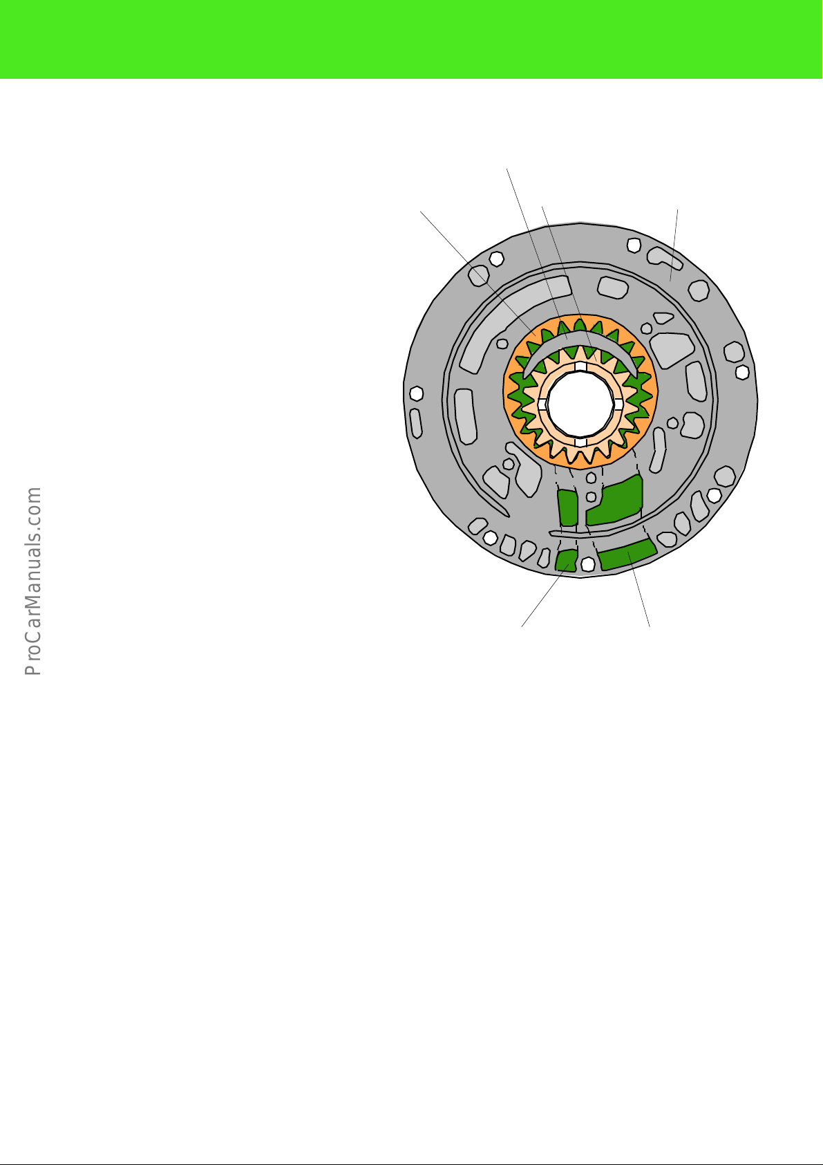
Torque Converter Lock-up Clutch
Torque converter lock-up clutch
Torque converter
housing
Friction lining
From engine
Torsion damper
SP21-6
It is a known fact that a torque converter becomes less economic as its rotational speed increases.
It does not transmit the full engine torque at high speeds.
That is why a lock-up clutch is integrated in the housing of the torque converter to ensure the entire
engine torque is transmitted.
The lock-up clutch is a mechanical clutch.
It is the means of creating a mechanical connection from the engine to the automatic gearbox by
means of the friction lining.
The torque converter is locked up (and thus is taken out of action) in certain driving situations.
It is disengaged and engaged electro-hydraulically by solenoid valve N91 in line with the actuation by
the control unit. The working medium for this is the gear oil (automatic transmission fluid).
The lock-up clutch is connected to the turbine wheel.
Torsion dampers around the circumference of the lock-up clutch reduce the torsional oscillations of
the engine during the mechanical disengaging and engaging operation.
The torque converter lock-up clutch is operated irrespective of the gear engaged.
18
Page 18

Flow of hydraulic power -
the lock-up clutch is open
From engine
Pump wheel
Turbine wheel
Turbine shaft
SP21-33
Flow of mechanical power -
the lock-up clutch is closed
From engine
Torque converter housing
Lock-up clutch
Turbine shaft
SP21-34
19
Page 19

Torque Converter Lock-up Clutch
Operating principle of the lock-up clutch
It is the control unit which defines the
moment for closing or opening the
torque converter lock-up clutch. This
is controlled through the modulation
valve N91.
Oil pressure is applied alternately to 3 oil
passages for closing and opening the lockup clutch.
The 3-line principle together with the modulation valve N91 makes it possible to specifically increase and reduce the pressure
when the lock-up clutch is closed and
opened.
The result is smooth jerk-free closing.
The lock-up clutch is open
Hydraulic fluid flows through the passages
B and C.
Passage A is closed.
The hydraulic fluid leaving passage B flows
to the planetary gear where it lubricates the
components.
SP21-35
20
Oil passages
SP21-36
Page 20

Rear of lock-up clutch
The lock-up clutch closes
For closing the lock-up clutch, hydraulic
fluid is fed to passage A.
Passage C is opened. As a result, the oil
pressure at the rear of the lock-up clutch is
higher than at the front.
The friction lining moves against the torque
converter housing.
The mechanical power flow from the engine
to the gearbox is completed.
The planetary gear is lubricated through
passages A and B.
Friction lining
Torque converter housing
Front of lock-up
clutch
SP21-37
The lock-up clutch is opened
The hydraulic fluid is again fed through passage C.
Passage A is closed.
As a result, the pressure on the front of the
lock-up clutch increases.
The lock-up clutch opens.
The power now flows once again hydraulically from the pump wheel to the turbine
wheel.
Lubricating fluid is once again supplied
through passages B and C.
Front of lockup clutch
SP21-38
21
Page 21

Shift Elements
All the shift elements are active in addition to the torque converter lock-up clutch, multi-disc clutches
and multi-disc brakes. The purpose of the shift elements is to carry out gearshifts under load without
any interruption to the power flow. They are operated hydraulically.
Externally-toothed discs
Internally-toothed discs
Hydraulic plunger
Piston cover
Oil feed
Oil chamber downstream of hydraulic
plunger
Compression spring
Block diagram of multi-disc clutch K1 and K3
Multi-disc clutches
The multi-disc clutches (K1, K2, K3) consist of
internally-toothed discs (which are at the same
time the friction lining) and externally-toothed
discs and are connected by the disc carriers to
the rotating parts.
The number of internally-toothed and externally-toothed discs differs according to the
gearbox code and clutch.
The hydraulic plunger rotates together with its
oil filling.
The oil is supplied through the hollow turbine
shaft.
Oil chamber upstream of hydraulic
SP21-39
Clutch open
The multi-disc clutches K1 and K3 are "centrifugal force pressure-balanced" to ensure
smooth gearshifts.
A compression spring holds the multi-disc
clutch open at any speed when it is in the nonoperating state.
Hydraulic fluid in a pressureless state is constantly present upstream and downstream of
the hydraulic plunger.
It ensures a centrifugal force pressure balance
when the clutch is open and holds the clutch in
a defined initial state.
plunger
22
Page 22

Clutch closes
In order to close the multi-disc clutch, oil is
forced under pressure into the chamber
upstream of the hydraulic plunger.
As a result of the oil pressure the compression spring and the discs of the clutch are
compressed.
The turbine shaft and the small input shaft
are connected by means of the disc carriers
to the multi-disc clutch (in this case clutch
K3 for 3rd/4th gear).
Power transmission is possible; the power
flows into the planet carrier.
Externally-toothed
discs
Small input shaft (internallytoothed disc carrier)
Internally-toothed discs
Oil chamber upstream of hydraulic
plunger
Turbine shaft (externally-toothed
disc carrier)
SP21-40
Clutch opens
To open the clutch, the chamber upstream
of the hydraulic plunger is again made
pressureless.
As a result of the dropping oil pressure the
compression spring which is resting against
the hydraulic cylinder pushes the plunger
back into its initial position.
Clutch K3 opens.
Power transmission to the planet carrier is
again interrupted.
Hydraulic plunger
SP21-39
23
Page 23

Shift Elements
Multi-disc brake
Gearbox housing
Supporting in gearbox housing
Externally-toothed
discs
Dished washer
Internally-toothed
discs
Internally-toothed
disc carrier (=
planet carrier)
The automatic gearbox 01M features two
multi-disc brakes for holding the gearbox
components of the planet gear sets fixed.
Brake B1 = Reverse gear brake
Brake B2 = 2nd and 4th gear brake
The internally-toothed discs each are
positioned on the rotating internally-toothed disc carrier.
They are connected to the carrier by
means of a splined section.
Hydraulic plunger
Freewheel
housing
SP21-41
Block diagram of brake B1
The externally-toothed discs have
shaped lugs on the outside.
These permit them to be supported in the
slots in the gearbox housing.
The multi-disc brake is operated hydraulically in a similar way to the multi-disc
clutches.
The hydraulic plunger which is located in
the freewheel housing compresses the
disc set by means of a dished washera.
24
The number of discs differs according to
the gearbox/engine combination.
Page 24

Freewheel
Freewheel direction
Blocking direction
Gearbox housing
Outer race of freewheel
Inner race (planet
carrier)
Rollers
SP21-42
The freewheel is designed as a roller freewheel.
The rollers are located between the outer race -
which at the same time is the mounting for the
plunger of the multi-disc brake B1 - and the
inner race which is part of the planet carrier.
The outer race is supported by means of a lug in
the gearbox housing.
The rollers have play in the direction of rotation;
they permit the rotation.
The rollers move into the narrowing gap in the
blocking direction.
Inner race and outer race are connected. As a
result, rotation of the planet carrier is prevented.
The freewheel, in combination with the shift elements, are used to achieve smooth power
engagement.
25
Page 25

Power Flow
F B1
Let us recall:
The control unit operates the clutches and brakes through
the solenoid valves in the control valve housing in line
with the gear engaged.
The clutches K1, K2 and K3 pass the force on to the
planet gear set. They
The brake B1 holds the planet carrier fixed.
The freewheel F by means of which the
planet carrier is supported in 1st gear
(see example of 1st gear).
are multi-disc clutches with
internally-toothed discs and externally-toothed
discs, both are
connected to the rotating parts;
power flow in a controlled manner into a planet
gear set or to connect two parts of a planet gear
set to each other.
The hydraulic plunger rotates together with its
hydraulic fluid filling.
Clutch K2 drives the large sun wheel.
Clutch K1 drives the small sun wheel.
Clutch K3 drives the planet carrier.
The brake B2 holds the large sun wheel fixed.
Brakes B1, B2
are multi-disc brakes, the
internally-toothed discs being connected to the
rotating gearbox part,
externally-toothed discs fixed,
hydraulic plunger compresses the disc set,
are used for holding one part of the planet gear
set fixed.
26
Page 26

K
K3 K1 K2 B2
The torque converter lock-up clutch K with which the
mechanical force is passed from the engine to the gearbox (see example of 4th gear).
SP21-46
27
Page 27

Power Flow
Selector lever position N or P
Direction of travel
Turbine wheel
Differential with flange shafts
Intermediate gear set
(drive pinion)
Pump wheel
From engine
No torque is transmitted when the selec-
tor lever is in position N or P. This Neutral position is what we use to explain the
power flow diagram.
– The power flow diagram shows the
top part of the gearbox.
The bottom part has been deleted
to simplify the illustration.
– The power flow which exists is indi-
cated in the individual gears by
using colour
– Gears and shafts are represented
by rectangles or dashes.
– Parts held fixed are connected to
broken lines.
B 2
K 2
Large sun wheel
K 1
K 3
Small sun wheel
F
Planet carrier
B 1
Hollow gear
Hollow gear
Input gear
SP21-20
Input gear
Planet carrier
SP21-16
are symbols for freewheel
are symbols for clutches or brakes
28
The power transmitted from the planet gear set
to the intermediate gear set passes in all the
gears through the hollow gear which is permanently connected to the input gear.
The hollow gear has been represented in the
diagram as a dash to simplify the illustration.
Page 28

K 1
F
Selector lever position R = Reverse
K 2
B 1
SP21-27
Pump wheel Turbine wheel
Selector lever position D or 1 = 1st gear
Brake B1 holds the
planet carrier fixed
Ratio of reverse = 2.88
Clutch K2 is closed by the
selector lever, large sun
wheel driven
Pump wheel Turbine wheel
Clutch K1 drives
the small sun wheel
Ratio of 1st gear = 2.71
SP21-21
Planet carrier orbits around freewheel F
29
Page 29

Power Flow
B 2
K 1
K 1
K 3
Selector lever position D or 2 = 2nd gear
SP21-22
Pump wheel Turbine wheel
Selector lever position D or 3 = 3rd gear
Clutch K1 drives
the small sun
wheel
Ratio of 2nd gear = 1.44
Brake B2 holds the large
sun wheel fixed
Pump wheel Turbine wheel
As the small sun wheel and the planet carrier are
driven, the entire planetary gear set rotates.
30
Clutch K1 drives
the small sun wheel
Ratio of 3rd gear = 1.00
SP21-23
Clutch K3 drives
the planet carrier
Page 30

Selector lever position D = 4th gear
B 2
K 3
B 2
K 3
SP21-25
Pump wheel Turbine wheel
The planet gear set rotates around the large sun
wheel.
4th gear with lock-up clutch
Brake B2 holds the
large sun wheel
fixed
Ratio of 4th gear = 0.74
Clutch K3 drives the planet carrier
Torque converter housing
Lock-up clutch
Brake B2 holds the
large sun wheel
fixed
Ratio of 4th gear = 0.74
SP21-26
Clutch K3 drives
the planet carrier
31
Page 31

Overview of System
Sensors
Throttle valve potentiometer G69 (through
engine control unit)
Gearbox speed sender G38
Automatic gearbox control unit
J217
Road speed sender G68
Engine speed sender G28
(through engine control unit)
Multifunction switch F125
Brake light switch F
Kickdown switch F8
Gear oil temperature
sender G93
32
Connection for self-diagnosis
Page 32

Actuators
Control valve body with solenoid
valves N88 - N94
Selector lever lock solenoid N110
Starter lockout and reversing light
relay J226
Additional signals
Engine control unit
Air conditioning/shut-off of magnetic coupling through AC control
unit
SP21-3
33
Page 33

Sensors
SP172/21
Engine speed sender G28
The control unit of the automatic gearbox uses
the engine speed signal of the relevant engine
management system.
Use of signal
– The control unit compares the engine speed
and the road speed.
The control unit detects the slip of the lockup clutch from the difference in the speeds.
– If the slip is too large (speed difference) the
control unit increases the contact pressure of
the lock-up clutch and thus reduces the slip.
– The signal supplied by the engine speed
sender is used by the control unit as a substitute parameter
Engine control unit
Substitute function
In the event of a signal failure, the control unit
moves into the emergency running mode.
Self-diagnosis
If an engine speed of less than 450 rpm exists at
a gearbox input speed of at least 2000 rpm, this
is detected as a fault. This is the case in the
event of an open circuit, short circuit or a signal
level which is too low.
Electric circuit
19 Signal wire
42 Screening
64 Supply voltage
J217 Automatic gearbox control unit
34
SP21-55
Page 34

SP172/18
Gearbox oil temperature sender
G93
The gearbox oil temperature sender G93 is an
NTC resistor.
It reduces its resistance as the oil temperature
rises.
Use of signal
If the ATF temperature reaches the limit of
150˚C, the lock-up clutch is closed.
This reduces the load on the torque converter
and the ATF cools down.
Should this measure not be adequate, the control unit shifts the gearbox down a gear.
Substitute function
If an excessively high temperature has already
been detected, the gearshifts are carried out at
higher shift points. Otherwise, an ATF temperature below the limit temperature is assumed.
Overheating can no longer be determined.
Self-diagnosis
Short circuit to earth and open circuit are
detected as faults in the self-diagnosis.
A particular feature should be noted in respect of
fault diagnosis.
The processor is not able to electrically distinguish a cold sensor from an open circuit in the
wiring. That is why a gearbox state has to exist
in which the sensor is reliably warm.
Electric circuit
6 ATF temperature signal
67 Supply voltage
J217 Automatic gearbox control unit
SP172/20
35
Page 35

Sensors
SP21-7
Road speed sender G68
The sender is an inductive sensor. The information regarding road speed is detected from the
pulse rotor at the input gear.
Use of signal
The information regarding road speed is
required in the control unit for
– determining which gear should be engaged
– controlling torque converter slip
Substitute function
In the event of a signal failure, the engine speed
is used as a substitute function.
The lock-up clutch is no longer closed.
Self-diagnosis
"No signal" is detected in self-diagnosis.
Electric circuit
SP21-45
20 Signal wire
43 Screening
65 Output voltage
J217 Automatic gearbox control unit
SP21-56
36
Page 36

Gearbox speed sender G38
The sender is an inductive sensor.
It is located in the gearbox housing and detects
the speed of the large sun wheel in the planet
gear.
SP21-44
SP21-8
Use of signal
The speed of the large sun wheel makes it possible for the control unit to exactly detect the
moment of a gearshift.
The speed signal is used by the control unit for
more accurately calculating the following functions:
– Reducing engine torque during the gearshift
by retarding the ignition angle
– Controlling the multi-disc clutches during the
gearshift
Substitute function
In the event of a signal failure, the control unit
moves into the emergency running mode.
Self-diagnosis
"No signal" is detected in self-diagnosis.
Electric circuit
21 Signal wire (pulses)
44 Screening
66 Output voltage
J217 Automatic gearbox control unit
SP21-57
37
Page 37

Sensors
Throttle valve potentiometer G69
The throttle valve potentiometer is connected to
the throttle valve. It constantly supplies information regarding the position of the throttle valve
and the operating rate of the accelerator pedal to
the control unit.
The information passes through the engine control unit to the automatic gearbox control unit.
SP21-50
Use of signal
The information is used for:
– Computing the load-related shift point
– Setting the load-dependent oil pressure in line
with the gear
The control unit computes the shift points for the
automatic gearbox on the basis of the operating
rate of the accelerator pedal.
Substitute function
A signal failure results in the following effects:
– The control unit assumes a moderate engine
load for the shift point.
– The ATF pressure is set to full throttle pres-
sure in line with the gear.
– The shift programmes can no longer be car-
ried out by the control unit.
Self-diagnosis
The throttle valve potentiometer G69 is included
in the self-diagnosis.
38
Electric circuit
41 Load signal through engine control unit
13 Influencing ignition timing
G69 Throttle valve potentiometer
J217 Automatic gearbox control unit
J220 Engine control unit
depending on
J361 Engine control unit
engine assignment
SP21-58
depending on
}
engine assignment
Page 38

SP172/23
Kickdown switch F8
The kickdown switch is integrated in the accelerator cable.
It is the means of detecting when the accelerator
pedal is depressed beyond the full throttle point.
It operates as an NO contact to earth.
The contact is closed when the switch is operated.
Use of signal
When the switch is operated, the gearbox shifts
immediately into the appropriate gear.
The control unit takes into account engine
speed. In addition, upshifts are carried out at
higher engine speeds.
If a high engine power is required in the kickdown mode, the air conditioning is switched off
for up to 8 seconds.
Substitute function
In the event of a signal failure, the kickdown shift
point is effected at approx. 95 % of the full throttle value of the load potentiometer.
Self-diagnosis
When the switch is operated, the engine control
unit checks with the aid of the load potentiometer
whether the throttle valve is fully opened. If a
non-conformity situation exists, this is detected
as a fault. No check is conducted if the vehicle is
not moving.
Electric circuit
16 Kickdown signal
J217 Automatic gearbox control unit
SP21-59
39
Page 39

Sensors
SP21-49
Multifunction switch F125
The multifunction switch is located above the
shift shaft in the gearbox housing.
It is operated directly by means of a cable in line
with the movement of the selector lever.
Selector lever positions P, R, N, D, 3, 2, 1 result
from the shift contacts.
Use of signal
– The multifunction switch transmits the selector
lever position to the automatic gearbox control
unit. It analyses this information and operates
the gearbox control accordingly.
– Actuation of the reversing light relay
– Blocking the starter when a gear is engaged
Substitute function
In the event of a fault, the automatic gearbox
control unit assumes selector lever position "D".
This results in the following reactions:
In selector lever position "D", "3" and "2" = all 4
gears are engaged automatically, manual selection of 3rd and 2nd gear is inactive.
A special case applies to engaging 1st gear. If
4th gear was engaged, it then remains engaged.
If 3rd, 2nd or 1st gear was engaged, 1st gear is
engaged. Selector lever positions "P", "R", "N"
remain;
starting is possible in "P", not in "N"
Self-diagnosis
Open circuits as well as short circuits to the control unit can be detected as faults if they result in
an incorrect combination.
An unplugged connector is detected as a fault.
Electric circuit
F125 Multifunction switch
J217 Automatic gearbox control unit
J226 Starter lockout and reversing light relay
Refer to selector lever positions for PIN number.
40
SP21-47
Page 40

Selector lever positions
The selector lever position is transmitted to the
gearbox control by the multifunction switch F125
along four coding wires.
Switch contacts 1, 2, 5 and 6 run directly to pins
63, 40, 18 and 62 of the gearbox control unit.
The switch is connected by 2 wires to terminal
15 (system voltage) and to terminal 31 (earth).
Shift stages
6/62 2/40
P
R
N
D
3
The four two-pin switches of the multifunction
switch result in the seven shift combinations of
the shift stages for the selector lever positions.
P = Gearbox output locked mechanically
1/633/5/187/ +
R = Reverse gear range
N = Neutral, no torque transmission
D = Forward gear range, all 4 gears shifted
automatically
3 = Forward gear range, 3 gears are shifted
automatically
4th gear is not engaged
2 = Forward gear range, 2 gears are shifted
automatically
3rd and 4th gear are not engaged
2
1 = Forward gear range, only 1st gear is
used
1
SP21-48
Note:
The position of selector lever relative to the multifunction switch is of importance for
the gearbox function.
Positions P, R, N and D are also transmitted mechanically to the selector slide valve in
the hydraulic shift control unit.
That is why the selector lever cable has to be exactly set.
Information regarding this is provided in the Workshop Manual OCTAVIA, Automatic
Gearbox.
41
Page 41

Sensors
Brake light switch F
The brake light switch F is located at the brake
pedal.
It operates as a NO contact to terminal 30.
When the brake is operated, information is supplied to the automatic gearbox control unit.
Use of signal
The "brake operated" information is required for
cancelling the "selector lever lock" function.
The selector lever can be moved out of position
P or N when the vehicle is stationary only if the
brake pedal is depressed.
SP172/99
Substitute function
In the event of a signal failure, the brake light
switch is assumed to be operated.
The selector lever lock (shiftlock) is cancelled,
the selector lever is no longer blocked.
Self-diagnosis
The brake light switch is detected in function 08,
Reading measured value block.
Electric circuit
F Brake light switch
15 Signal wire
30 Positive
J217 Automatic gearbox control unit
M9 Brake light
M10 Brake light
SP21-51
42
Page 42

SP21-67
Actuators
Selector lever lock solenoid N110
(shiftlock solenoid)
The solenoid is located at the shift mechanism.
It is connected on the one side to terminal 15, is
operated with the ignition and mechanically locks
the selector lever to prevent a gear being engaged.
The second connection is linked to the automatic
gearbox control unit.
The shiftlock is only cancelled when the brake
pedal is depressed (refer also to brake pedal
switch F).
The selector lever can be moved into any drive
position.
A visual indication is provided in the illuminated
selector lever display to show that the shiftlock is
engaged.
This indicator goes out when the brake pedal is
operated.
Reaction in the event of a fault
If an open circuit exists, the selector lever lock is
cancelled.
If a short to earth exists, the selector lever is
blocked in position "P" or "N".
Self-diagnosis
The solenoid is checked for open circuit and short
to earth and is included in function 08, Reading
measured value block.
Electric circuit
15 Terminal 15
29 Signal output (earth) of control unit
L19 Bulb for illuminating selector lever display
J217 Automatic gearbox control unit
N110 Selector lever lock solenoid
SP21-52
43
Page 43

Actuators
SP172/29
Solenoid valves N88 to N94
Solenoid valves N88 to N94 are located in
the control valve housing of the gearbox.
The control valve housing is the actual
hydraulic shift control unit of the automatic
gearbox.
All the solenoid valves are directly connected to the automatic gearbox control unit.
They are supplied with the output information which is required for the hydraulic gearshifts in line with the shift programme, by the
automatic gearbox control unit.
Use of signal
Solenoid valves N88, N89, N90, N92 and
N94 are OPEN/CLOSED valves.
N94
SP172/30
N89
N88
N92
N90
They are either open or closed and open or
close an oil passage each.
– The gears defined by the control unit
are engaged by means of the valves
N88, N89 and N90 (shift solenoid
valves).
– The smoothness of the gearshift is
influenced by the valves N92 and N94
(control solenoid valves.
Solenoid valves N91 and N93 (control
solenoid valves) are modulation valves.
The level of the clutch pressure required is
set by means of these two valves. The control is carried out steplessly. The control unit
determines the level of the amperage. The
clutch pressure alters in line with the amperage.
– Valve N91 controls the clutch pres-
sure for the lock-up clutch.
– Valve N93 controls the pressure of the
multi-disc clutches and multi-disc
brakes.
N93
N91
SP172/31
44
Page 44

SP172/105
Substitute function
In the event of a fault, the automatic gearbox
control unit switches to the emergency running
mode.
In this case, the gearbox shifts into hydraulic 3rd
gear when driving, taking into account the speed
of the vehicle and the position of the selector
lever.
Self-diagnosis
All the valves are checked for open circuit and
short to earth as soon as the ignition is switched
on.
The check is continued on a permanent basis.
The solenoid valves can be interrogated individually in function 02, Interrogating fault memory.
Electric circuit
9 Solenoid valve N90
10 Solenoid valve N94
22 Supply voltage N93
47 Solenoid valve N91
54 Solenoid valve N89
55 Solenoid valve N88
56 Solenoid valve N92
58 Solenoid valve N93
67 Supply voltage of solenoid valves
J217 Automatic gearbox control unit
SP21-53
45
Page 45

Actuators
Starter lockout and reversing
light relay J226
The relay is a combination relay.
In the OCTAVIA it is located at relay position 11
of the additional relay carrier.
The relay is connected directly to the output of
the automatic gearbox control unit (pin 11).
The output is connected to earth if the selector
lever is in position P or N (Park/Neutral signal).
It is only possible to start the car in these positions.
In the event of an open circuit in the wiring, it is
only possible to start the car in "P".
SP21-64
The reversing lights are also operated through
this relay if reverse gear is engaged.
The signal in this case comes from the multifunction switch once the selector lever is in position
"R".
Self-diagnosis
Not included in self-diagnosis.
Electric circuit
F125 Multifunction switch
J217 Automatic gearbox control unit
J226 Starter lockout and reversing light
relay
B/50 Starter terminal 50
D/50 Ignition/starter switch terminal 50
M16/17 Reversing lights
11 P, N signal
18 P, R, N signal
63 P signal
46
SP21-54
Page 46

8 s
OT
Additional signals
To engine control unit
The automatic gearbox control unit is linked
directly to the engine control unit.
Information flows through this output if engine
torque is to be reduced during a gearshift by
altering the ignition timing.
Gear shift
The engine control unit makes use of this signal
to briefly retard the ignition timing in order to
reduce engine torque.
This improves the quality of the gearshifts by
achieving smoother shifting.
SP21-62
To air conditioning system
The automatic gearbox control unit signals to the
air conditioning control unit when the kickdown
switch is operated
The magnetic clutch of the AC compressor is
switched off in this case for up to 8 seconds.
Full engine output is then available for accelerating.
The air conditioning is likewise switched off for
up to 8 seconds after the engine is started.
This minimises the load on the engine after it is
started.
SP21-61
47
Page 47

Subsystems
Selector lever lock (shiftlock)
Shift linkage with locking link
The selector lever lock (shiftlock) is a technical
safety measure on automatic gearboxes. This
makes it possible to eliminate incorrect operation on
the part of the driver.
It operates electro-mechanically.
The P/N position.
The selector lever is locked electro-mechanically in
selector lever positions P and N.
This eliminates any risk of unintentionally starting off
when a gear is engaged mechanically (R, D, 3, 2, 1).
SP21-66
A locking pin is inserted mechanically into the
locking link of the shift mechanism of the selector lever when it is in position P and N by
means of a solenoid (refer also to the section
on Actuators - selector lever lock solenoid).
This lock is released only when the brake
pedal is depressed.
Locking pin of selector lever
lock solenoid
48
Page 48

Function diagram for P/N position
(block diagram)
F125
J217
N110
P
P
R
N
N
D
3
2
1
the driver into position P or N.
This position is detected by the multifunction
switch F125 and signalled to the automatic
gearbox control unit J217.
The control unit activates the lock through the
selector lever lock solenoid N110 and the
selector lever is locked mechanically by the
solenoid.
When the footbrake is depressed, a pulse is
supplied by the brake light switch F to the
The selector lever is moved mechanically by
F
control unit.
The control unit thereupon actuates the
selector lever lock solenoid to cancel the
mechanical lock.
SP21-60
The selector lever lock solenoid releases the
locking pin
It is now possible to engage a gear.
Note:
A time lag element is incorporated in the functional sequence.
This ensures that the selector lever is not locked if it is shifted briskly through "N"
(e.g. from R to D and D to R for "rocking" free a car which has become stuck in
snow).
The selector lever lock function is activated, however, if the selector lever
remains in position "N" for more than 2 seconds.
The selector lever lock in position "N" is automatically switched off if the vehicle
speed is greater than 5 km/h.
49
Page 49

Subsystems
Park lock
Park lock gear
Drive gear
Intermediate gear stage
Driving shaft
SP21-9
Detent lever
Engaging lever
The park lock is a means of securing the vehicle
from moving off, in addition to the parking brake.
It is engaged purely mechanically when the selector lever is in position "P" and the vehicle is
stationary.
The park lock acts on the intermediate gear
stage of the automatic gearbox.
The park lock gear, like the drive gear of the
intermediate gear stage, is permanently attached to the driving shaft.
If the selector lever is moved into position "P",
the shift shaft moves the engaging lever against
the detent lever.
The detent lever moves up into the tooth gap of
the park lock gear.
The intermediate gear stage is blocked, the vehicle is secured.
Shift shaft
SP21-65
If the detent lever strikes against a tooth and
does not move into the gap when the selector
lever is moved into position "P", it is tensioned by
a spring.
The slightest movement of the vehicle then
causes the detent lever to jump into the gap.
Detent lever and the teeth of the park lock gear
are shaped so that the detent lever cannot
engage if the park lock gear is rotating at a high
speed.
This eliminates any risk of the gearbox blocking
when driving.
50
Page 50

Emergency Programme/Emergency Running Mode
The electronic system in the automatic gearbox
01M is a rugged design.
Fault analysis shows that 90% of all failures are
likely to be caused by wiring, plug connections,
sensor or actuators.
The electronic system is designed so as to
switch to a substitute signal or to assume a substitute value in the event of an input signal not
being received (see substitute functions under
Sensors/Actuators)
= emergency programme.
The electronic control system actuates the func-
SP21-63
tions so as to avoid any consequential damage.
The car can still be driven!
If an essential signal is not received or if an actuator or the electronic control itself fails, and no
substitute signal can be formed, the system
switches into
= emergency running mode.
The gearbox then operates as a purely hydraulic
gearbox. The torque converter lock-up clutch is
switched off.
The selector lever remains coupled mechanically
to the selector lever slide valve to enable the
vehicle to move.
The gearbox can still be shifted manually into the
selector lever positions.
In selector lever positions D, 3 and 2, however,
only 3rd gear is available.
In selector lever position 1 and R the relevant
gear is available.
Note:
Failure of a secondary signal can be felt by a deterioration in the smoothness of the
gearshifts (shift jolts are noticeable).
The emergency programme sets a fault memory which can be read in self-diagnosis.
The emergency running mode is retained until the fault is rectified.
51
Page 51

Self-Diagnosis
The self-diagnosis
monitors the signals of the sensors and also the operation of the actuators electrically and carries out a
self-test of the gearbox control unit.
If a fault occurs, substitute functions are activated.
The faults are stored in the permanent fault memory
of the control unit.
Consequently, the fault messages are retained even
if the battery is disconnected or the connector of the
control unit is unplugged.
The diagnostic connection
acts as a diagnostic interface and makes it possible
to rapidly transfer data from the gearbox control unit
to the vehicle system tester and in the opposite
direction.
The faults can be read using the vehicle system
tester V.A.G 1552 with programme card 3.
Note:
It is also possible to use fault reader V.A.G 1551.
In this case, use programme card 7.
The integrated printer makes it easier to structure the detection of the measured
values.
By selecting the address word
SP17-29
02 Gearbox electronics
it is possible to select the following functions of data transfer:
01 – Interrogating control unit version
02 – Interrogating fault memory
04 – Initiating basic setting
05 – Erasing fault memory
06 – Ending output
08 – Reading measured value block
52
Page 52

All the sensors and actuators which are colour-coded are monitored by the self-diagnosis and can be
tested using function 08 - Reading measured value block.
Note:
After completing certain repairs or replacing components, it is
then necessary to restore the system to the basic setting (function 04 - Initiating basic setting).
This is the case, for example, after:
replacing the engine,
replacing the engine control unit,
replacing the throttle valve control unit,
replacing the automatic gearbox control unit,
or replacing clutches or the control valve housing.
For the precise procedure regarding self-diagnosis refer to the Workshop Manual OCTAVIA, Automatic
Gearbox
SP21-43
53
Page 53

Function Diagram
The function diagram represents a
simplified current flow diagram
and shows how all the system
components of the gearbox control are interlinked.
Components
A Battery
B/50 Starter (terminal 50)
D/50 Ignition/starter switch
(terminal 50)
F Brake light switch
F8 Kickdown switch
F125 Multifunction switch
G28 Engine speed sender
G38 Gearbox speed sender
G68 Road speed sender
G69 Throttle valve potentiometer
G93 Gearbox oil temperature
sender
J226 Starter lockout and reversing
light relay
J217 Automatic gearbox control unit
J220 Motronic control unit
J361 Simos control unit
L19 Bulb for illuminating selector
lever display
M16/M17 Bulbs for reversing lights
M9/M10 Bulbs for brake and tail light
N88 Solenoid valve 1
N89 Solenoid valve 2
N90 Solenoid valve 3
N91 Solenoid valve 4
N92 Solenoid valve 5
N93 Solenoid valve 6
N94 Solenoid valve 7
N110 Selector lever lock solenoid
valve
S... Fuses
Additional signals
Colour coding/Legend
1
AC cut-off at kickdown
54
= Input signal
= Output signal
= Positive
= Earth
Page 54

A2
A40
U2
Positive connection 15 in wiring loom
Positive connection 30 in wiring loom
Positive connection 15 in wiring loom
SP21-15
55
 Loading...