

Page 1
SIMPLY CLEVER
ŠKODA Rapid Spaceback
Owner's Manual
Page 2

5JJ012720AC
Page 3

Page 4

Preface
You have opted for a ŠKODA – our sincere thanks for your confidence in us.
The description of the vehicle operation, important information about safety, vehicle care, mainte-
nance and self-help, as well as technical vehicle data, are given in this manual.
Please read this Owner's Manual carefully, because operation in accordance with these instructions is
a prerequisite for proper use of the vehicle.
We hope you enjoy driving your ŠKODA, and wish you a pleasant journey at all times.
Your ŠKODA AUTO a.s. (hereinafter referred to only as ŠKODA or manufacturer)
5JJ012720AC
Page 5

Table of Contents
Board literature 4
Notes 5
Structure and more information about the
Operating Instructions 6
Abbreviations
Safety
Passive Safety 8
General information 8
Correct and safe seated position 9
Seat belts 12
Using seat belts 12
Inertia reels and belt tensioners 15
Airbag system 16
Description of the airbag system 16
Airbag overview 17
Deactivating airbags 20
Transporting children safely 22
Child seat 22
Fastening systems 25
Using the system
Cockpit 29
Overview
Instruments and Indicator Lights
Instrument cluster
Indicator lights
Information system
Driver information system
Multifunction display (MFD)
28
30
30
34
43
MAXI DOT display 46
Service interval display 47
Unlocking and opening 49
Unlocking and locking 49
Anti-theft alarm system 53
Luggage compartment lid 54
Power windows 55
Mechanical windows 57
Lights and visibility 58
Lights 58
Interior lighting 63
Visibility 64
Windscreen wipers and washers 65
Rear mirror 67
Seats and head restraints 69
Seats and head restraints 69
Seat features 71
Transporting and practical equipment 73
Useful equipment 73
Luggage compartment 80
Variable loading floor in the luggage
compartment (Estate) 85
Roof rack 88
Heating and air conditioning 89
Heating, ventilation, cooling 89
Communication and multimedia 94
Universal telephone installation GSM II 94
Voice control 98
Multimedia 99
SmartGate 101
41
Driving
41
Starting-off and Driving 104
Starting and turning off the engine 104
Brakes and parking 106
Manual gear changing and pedals 107
Automatic gearbox 108
Retraction and economical driving 111
Driving through water and driving off made-
up roads 111
Assist systems 113
Braking and stabilisation systems 113
Parking aid 114
Cruise Control System 115
START-STOP 116
Tyre pressure monitoring 119
Hitch and trailer 120
Hitch 120
Trailer 125
General Maintenance
Care and maintenance 128
Service work, adjustments and technical
alterations 128
Washing vehicle 131
Cleaning vehicle exterior 132
Interior care 136
Inspecting and replenishing 138
Fuel 138
Engine compartment
Engine oil 144
Coolant 146
Brake fluid 147
Vehicle battery 148
Wheels 152
Tyres and wheel rims 152
Manufacturer-approved tyre variants 155
Winter operation 156
141
2
Table of Contents
Page 6

Do-it-yourself
Emergency equipment and self-help 158
Emergency equipment 158
Reserve and temporary spare wheel 159
Changing a wheel 160
Puncture set 164
Jump-starting 166
Towing the vehicle 168
Remote control 170
Emergency unlocking/locking 170
Replacing windscreen wiper blades 171
Fuses and light bulbs 173
Fuses 173
Replacing bulbs 176
Technical data
Technical data
Vehicle data 181
181
Index
Table of Contents
3
Page 7

Board literature
You always find these Operating Instructions and the Service Plan in the onboard literature for your vehicle.
Depending on the equipment, the on-board literature can also contain The ra-
dio instruction manual or Manual of the navigation systemand in some countries also the brochure On the road.
Owner's Manual
These operating instructions apply to all body variants of the vehicle and all
related model versions as well as all equipment levels.
This owner's manual describes all possible equipment variants without identifying them as special equipment, model variants or market-dependent equipment. Consequently, this vehicle does not contain all of the equipment com-
ponents described in this Owner's Manual.
The level of equipment in your vehicle refers to your purchase contract for the
vehicle. For questions regarding the scope of equipment, please contact a
ŠKODA Partner, if required.
The Pictures in this manual are for illustrative purposes only. The illustrations
can differ in minor details from your vehicle; they are only intended to provide
general information.
ŠKODA AUTO a.s. pursues a policy of constant product and model development. Changes in terms of supply scope are possible at any time with regard to
design, equipment and technology. The information listed in this operating
manual corresponds to the information available at the time of going to press.
It is therefore not possible for legal claims to be made based on the technical
data, illustrations and information contained in this Owner's Manual.
Service schedule
The service plan includes the documentation of the vehicle handover information with regard to warranty and service events.
The radio instruction manual
The instruction manual of the radio contains a description of the operation of
the radio, and possibly also some functions and vehicle systems.
Instruction manual of the navigation system
The instruction manual of the navigation system includes a description of the
operation of the navigation system, and possibly also some functions and vehicle systems.
On The Move Brochure
The On The Move Brochure contains phone numbers of importers and service
offices in individual countries and emergency numbers.
4
Board literature
Page 8

Notes
Terms used
The on-board literature contains the following terms relating to the service
work for your vehicle.
“Specialist garage”
ŠKODA vehicles. A specialist garage can be a ŠKODA partner, a ŠKODA
service partner or an independent workshop.
“ŠKODA service partner”
by the manufacturer ŠKODA AUTO a.s. or its sales partner to perform
service tasks on ŠKODA vehicles and to sell ŠKODA Genuine Parts.
“ŠKODA partner”
ŠKODA AUTO a.s. or its sales partner to sell new ŠKODA vehicles and,
when applicable, to service them using ŠKODA Genuine Parts and sell
ŠKODA Genuine Parts.
Explanation of symbols
An overview of the symbols used in the instruction manual and a brief explanation of their meaning.
Reference to the introductory module of a chapter with important infor-
mation and safety warnings.
Continuation of the module on the next page.
Situations where the vehicle must be stopped as soon as possible.
® Trademark.
Telephone operation in the MAXI DOT display.
Text display in the segment display.
WARNING
Texts with this symbol draw attention to threats of a serious accident, injury or loss of life.
- a workshop that carries out specialist service tasks for
- A Workshop that has been contractually authorised
- A company that has been authorised by the manufacturer
Note
Texts with this symbol contain additional information.
CAUTION
Texts with this symbol draw attention to the risk of vehicle damage or possible
inoperability of some systems.
For the sake of the environment
Texts with this symbol contain information on environmental protection as
well as tips for economical operation.
Notes
5
Page 9

Structure and more information about the Operating Instructions
Structure of the manual
The operating manual is hierarchically divided into the following areas.
■
Section (e.g. Safety) - the title of the Section is always indicated at the lower
left side
■
Main chapters (e.g. Airbag System) - the title of the main chapter is always
indicated at the lower right side
■
Chapter (e.g. Airbag Overview)
■
Introduction to the topic - Module Overview within the chapter intro-
ductory information about the chapter content, if necessary, valid for
the entire chapter notes
■
Module (e.g. Front Airbags)
Information Search
When searching for information in the operating instructions, we recommend
using the Index at the end of the manual.
Direction indications
All direction indications such as “left”, “right”, “front”, “rear” relate to the forward direction of travel of the vehicle.
Units
The volume, weight, speed and length data are given in metric units, unless
otherwise indicated.
Display
In this owner's manual, the screen on the MAXI DOT display is used as the display illustration, provided nothing is otherwise stated.
6
Structure and more information about the Operating Instructions
Page 10

Abbreviations
Abbreviation Definition
rpm Engine revolutions per minute
A2DP
ABS Anti-lock brake system
AG Automatic gearbox
AGM Vehicle battery type
TCS Traction control
CO
DPF Diesel particle filter
DSG Automatic double clutch gearbox
EDL Electronic differential lock
ECE Economic Commission for Europe
EPC EPC fault light
ESC Electronic Stability Control
ET Rim depth
EU European Union
GSM Global System for Mobile communications
HBA Hydraulic brake assist
HHC Uphill start assist
kW Kilowatt, measuring unit for the engine output
MDI Inputs for connecting external devices
MFD Multifunction display
MG Manual gearbox
MPI Gasoline engine with a multi-point fuel injection
N1
Nm Newton meter, measuring unit for the engine torque
PIN personal identification number
SIM card a card for the identification of the mobile network operator
a Bluetooth software profile for a one-way transfer of audio
data
Carbon dioxide
2
Panel van intended exclusively or mainly for the transportation of goods
Abbreviation Definition
TDI CR
TSI Petrol engine with turbo charging and direct injection
VIN Vehicle identification number
Wi-Fi wireless data network
Diesel engine with turbo charging and common rail injection
system
Abbreviations
7
Page 11

Safety
Passive Safety
General information
Introduction
This chapter contains information on the following subjects:
Before setting off
Driving safety 8
Safety equipment 8
In this section you will find important information, tips and notes on the subject of passive safety in your vehicle.
We have combined everything here which you should be familiar with, for example, regarding seat belts, airbags, child seats and safety of children.
WARNING
■
This chapter contains important information on how to use the vehicle for
the driver and his occupants.
■
You can find further information on safety concerning you and those trav-
elling with you in the following chapters of this owner's manual.
■
The complete on-board literature should always be in the vehicle. This
applies in particular, if you rent out or sell the vehicle.
Before setting off
Read and observe on page 8 first.
For your own safety and the safety of the people travelling with you, please
pay attention to the following points before setting off.
Ensure that the lighting and the turn signal system are functioning proper-
ly.
Ensure that the function of the wipers and the condition of the wiper
blades are free of any defects.
Ensure that all of the windows offer good visibility to the outside.
Adjust the rear-view mirror so that vision to the rear is guaranteed.
Ensure that the mirrors are not covered.
Check the tyre inflation pressure.
Check the engine oil, brake fluid and coolant level.
Secure all items of luggage.
Do not exceed the permissible axle loads and permissible gross weight of
the vehicle.
Close all doors as well as the bonnet and boot lid.
Ensure that no objects can obstruct the pedals.
Protect children in suitable child seats with correctly fastened seat
belts » page 22, Transporting children safely.
Adopt the correct seated position » page 9, Correct and safe seated
8
position. Tell your passengers to assume the correct seated position.
Driving safety
Read and observe on page 8 first.
The driver is fully responsible for himself and his occupants. If your driving
safety is effected, you place yourself and the oncoming traffic at risk.
The following guidelines must therefore be observed.
Do not become distracted from concentrating on the traffic situation, e.g.
by your passengers or mobile phone calls.
Never drive when your driving ability is impaired, e.g. due to medication, al-
cohol or drugs.
Keep to the traffic regulations and the permissible speed limit.
Always adjust the driving speed to the road, traffic and weather condi-
tions.
Take regular breaks on long journeys – at least every two hours.
Safety equipment
Read and observe
The following list contains only part of the safety equipment in your vehicle.
Three-point seat belts for all the seats.
›
Belt force limiters for the front seats.
›
Belt tensioners for the front seats.
›
Seat belt height adjusters for the front seats.
›
Front airbag for the driver and the front passenger.
›
Side airbags.
›
Head airbags.
›
Anchoring points for child seats using the ISOFIX system.
›
on page 8 first.
8
Safety
Page 12
Anchoring points for child seats using the TOP TETHER system.
›
Head restraints adjustable for height1).
›
Adjustable steering column.
›
The specified safety equipment works together, in order to optimally protect
you and those travelling with you in accident situations.
The safety equipment does not protect you or the people travelling with you, if
you or your occupants adopt an incorrect seated position or the equipment is
not correctly adjusted or used.
If the seat belt is not fastened properly, this may result in injuries if an airbag is
activated in the event of an accident.
Correct and safe seated position
Introduction
This chapter contains information on the following subjects:
Correct seated position for the driver
Adjusting the steering wheel position 10
Correct seated position for the front passenger 10
Correct seated position for the passengers in the rear seats 11
Examples of incorrect seated positions 11
WARNING
■
The front seats and all head restraints must be adjusted to match the
body size at all times and the seat belt must always be fastened properly to
provide the most effective levels of protection to the passengers.
■
Each occupant must correctly fasten the seat belt belonging to the seat.
Children must be fastened » page 22, Transporting children safely with a
suitable restraint system.
■
If the occupant adopts an incorrect seated position, he is exposed to lifethreatening injuries, in case he is hit by a deployed airbag.
■
If the occupants on the rear seats are not sitting upright, the risk of injury
is increased due to incorrect routing of the seat belt.
■
The seat backrests must not be tilted too far back when driving, as this
will impair the function of the seat belts and of the airbag system – risk of
injury!
Correct seated position for the driver
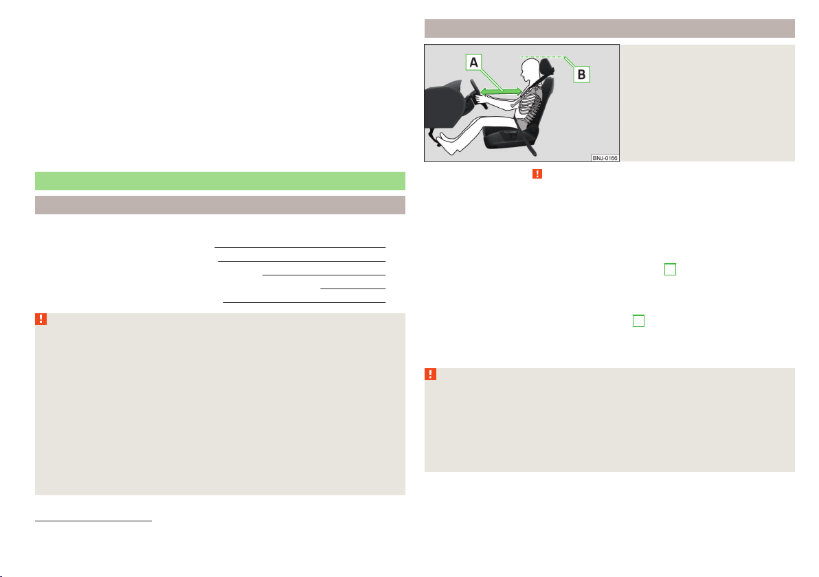
Fig. 1
The correct distance of the driver
to the steering wheel/correctly
adjusted head restraint
Read and observe on page 9 first.
For your own safety and to reduce the risk of injury in the event of an accident,
the following instructions must be observed.
Adjust the driver’s seat in the forward/back direction so that the pedals
can be fully depressed with slightly bent legs.
Adjust the seat backrest so that the highest point of the steering wheel
9
can be reached with your arms at a slight angle.
Adjust the steering wheel so that the distance A between the steering
wheel and your chest is at least 25 cm » Fig. 1. Adjust the steering
wheel » page 10, Adjusting the steering wheel position.
Adjust the head restraint such that the top edge of the head restraint is at
the same level as the top of your head 1) B » Fig. 1.
Correctly fasten the seat belt » page 12, Using seat belts.
Adjust the seats and head restraints » page 69.
WARNING
■
Always assume the correct seated position before setting off and do not
change this position while driving. Also advise your passengers to adopt
the correct seated position and not to change this position while the car is
moving.
■
Maintain a distance of at least 25 cm to the steering wheel. Not maintaining this minimum distance will mean that the airbag system will not be able
to properly protect you – hazard!
1)
Not valid for sports seat.
Passive Safety
9
Page 13
WARNING (Continued)
■
When driving, hold the steering wheel with both hands firmly on the outer edge in the “9 o'clock” and “3 o'clock” position. Never hold the steering
wheel in the “12 o'clock” position or in any other way (e.g. in the middle or
inner edge of the steering wheel). In such cases, you could severely injure
the arms, hands and head when the driver airbag is deployed.
■
Ensure that there are no objects in the driver's footwell as they may get
caught behind the pedals when driving or applying the braking. You would
then no longer be able to operate the clutch, brake or acceleration pedals.
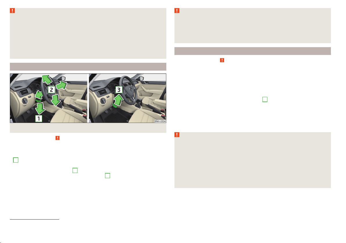
Adjusting the steering wheel position
Fig. 2 Adjusting the steering wheel position
Read and observe
The height and forward/back position of the steering wheel can be adjusted.
Swing the safety lever under the steering wheel in the direction of arrow
›
1
» Fig. 2.
Adjust the steering wheel to the desired position. The steering wheel can be
›
adjusted in direction of arrow 2.
Pull the holder until it stops in arrow direction 3.
›
on page 9 first.
WARNING
■
The lever for adjusting the steering wheel must be locked whilst driving
so that the steering wheel cannot accidentally change position during the
journey – risk of accident!
■
Never adjust the steering wheel when the vehicle is moving only when
the vehicle is stationary!
Correct seated position for the front passenger
Read and observe
For passenger safety and to reduce the risk of injury in an accident, the following instructions must be observed.
Position the front passenger seat back as far as possible. The front pas-
senger must maintain a distance of at least 25 cm to the dash panel so
that the airbag offers the greatest possible safety if it is deployed.
Adjust the head restraint such that the top edge of the head restraint is at
the same level as the top of your head 1) B » Fig. 1 on page 9.
Correctly fasten the seat belt » page 12, Using seat belts.
Adjust the seats and head restraints » page 69.
In exceptional cases the front passenger airbag can be deactiva-
ted » page 20, Deactivating airbags.
WARNING
■
Maintain a distance of at least 25 cm to the dash panel. Not maintaining
this minimum distance will mean that the airbag system will not be able to
properly protect you – hazard!
■
Always keep your feet in the footwell when the car is being driven – never place your feet on the instrument panel, out of the window or on the
surfaces of the seats. You will be exposed to increased risk of injury if it becomes necessary to apply the brake or in the event of an accident. If an airbag is deployed, you could suffer fatal injuries by adopting an incorrect
seated position!
on page 9 first.
1)
Not valid for sports seat.
10
Safety
Page 14

Correct seated position for the passengers in the rear seats
Read and observe on page 9 first.
To reduce the risk of injury in the event of a sudden braking manoeuvre or an
accident, the occupants on the rear seats must observe the following.
Adjust the head restraint such that the top edge of the head restraint is at
the same level as the upper part of the head B » Fig. 1 on page 9.
Correctly fasten the seat belt » page 12, Using seat belts.
Use a suitable child restraint system if transporting children in the vehicle » page 22, Transporting children safely.
Adjust the seats and head restraints » page 69.
Examples of incorrect seated positions
Read and observe
Maximum seat belt protection is only achieved if seat belts are fastened correctly.
Incorrect seated positions considerably reduce the protective functions of the
seat belts and therefore increase the risk of injury due to an incorrect routing
of the seat belt.
The driver is fully responsible for himself and passengers, especially children.
Never allow a passenger to adopt an incorrect seated position when the car is
moving.
The following list contains instructions which, if not observed, may cause serious injuries or death. This list is not complete, however we would like you to
familiarise yourself with this subject.
Observe the following instructions while driving.
Do not stand up.
Do not stand on the seats.
Do not kneel on the seats.
Do not tilt the seat backrest too far back.
Do not lean against the dash panel.
Do not lie on the rear seats.
Do not sit only on the front part of the seat.
Do not sit facing to the side.
Do not lean out of the window.
on page 9 first.
Do not put your feet out of the window.
Do not put your feet on the dash panel.
Do not put your feet on the seat cushion.
Do not allow anybody to travel in the footwell.
Do not drive without fastening your seat belt.
Do not delay in the luggage compartment.
Passive Safety
11
Page 15
Seat belts
Using seat belts
Introduction
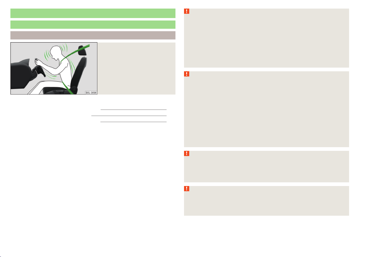
Fig. 3
Driver wearing seat belt
This chapter contains information on the following subjects:
The physical principle of a frontal collision 13
Fastening and unfastening seat belts 14
Belt height adjustment on the front seats 15
Seat belts that are fastened correctly offer good protection in the event of an
accident. They reduce the risk of an injury and increase the chance of survival
in the event of a major accident.
Correctly fastened seat belts hold occupants of the car in the correct seated
position » Fig. 3.
The seat belts reduce the kinetic energy (energy of motion) to a considerable
extent. They also prevent uncontrolled movements which, in turn, may well result in severe injuries.
Occupants of a vehicle who have correctly fastened their seat belts have the
major benefit of the fact that the kinetic energy is absorbed as effectively as
possible by the belts.
The structure of the front end of the vehicle and other passive safety measures, such as the airbag system, also contribute to the kinetic energy being reduced as effectively as possible. The energy produced is thus absorbed and
there is less risk of injury.
Particular safety aspects must be observed when transporting children in the
vehicle » page 22, Transporting children safely.
WARNING
■
Fasten your seat belt before each journey – even when driving in town!
This also applies to the passengers seated at the rear – risk of injury!
■
Expectant women must also always wear a seat belt. This is the only way
of ensuring optimal protection for the unborn child » page 14, Fastening
and unfastening seat belts.
■
Maximum seat belt protection is only achieved if you are correctly seated » page 9, Correct and safe seated position.
■
The seat backrests of the front seats must not be tilted too far to the rear
otherwise the seatbelts can lose their effectiveness.
WARNING
Information on the correct routing of the belt
■
Always ensure that the webbing of the seat belts is properly routed. Seat
belts which are not correctly adjusted can themselves cause injuries even
in minor accidents.
■
Adjust the height of the belt in such a way that the shoulder part of the
belt is roughly positioned across the middle of your shoulder – on no account across your neck.
■
A seat belt which is hanging too loose can result in injuries as your body is
moved forward by the kinetic energy produced in an accident and is then
suddenly held firm by the belt.
■
The belt webbing must not run across solid or fragile objects (e.g. spectacles, ball-point pens, bunches of keys etc.). Such objects can cause injury.
WARNING
Information on dealing with the safety belts
■
The belt webbing must not be jammed in-between at any point or twisted, or chafe against any sharp edges.
■
Make sure you do not catch the seat belt in the door when closing it.
WARNING
Information on the proper use of the safety belts
■
Never use one seat belt to secure two persons (including children). The
seatbelt must not be placed over a child who is sitting on the lap of another
passenger.
12
Safety
Page 16
WARNING (Continued)
■
The lock tongue should only be inserted into the lock which is the correct
one for your seat. Wrong use of the safety belt will reduce its capacity to
protect and the risk of injury increases.
■
The slot of the belt tongue must not be blocked, otherwise the belt
tongue will not lock in place properly.
■
Many layers of clothing and loose clothing (e. g. a winter coat over a jacket) do not allow you to be correctly seated and impairs proper operation of
the seat belts.
■
It is prohibited to use clamps or other objects to adjust seat belts (e. g. for
shortening the belts for smaller persons).
■
The seat belts for the rear seats can only fulfil their function reliably
when the seat backrests are correctly locked into position » page 72.
WARNING
Information on the care and maintenance of the safety belts
■
The belt webbing must always be kept clean. Soiled belt webbing may impair proper operation of the inertia reel » page 138.
■
The seat belts must not be removed or changed in any way. Do not attempt to repair the seat belts yourself.
■
Check the condition of all the seat belts on a regular basis. If any damage
to the seat belts, seat belt connections, inertia reel or the lock is detected,
the relevant seat belt must be replaced by a specialist garage.
■
Damaged seat belts which have been subjected to stress in an accident
and were therefore stretched, must be replaced – this is best done by a
specialist garage. The anchorage points of the belts must also be inspected. The anchorage points for the belts should also be checked.
Note
The national legal requirements must be observed when using seat belts.
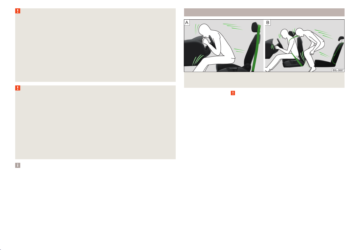
The physical principle of a frontal collision
Fig. 4 Driver without a fastened seat belt/rear seat passenger without a
fastened seat belt
Read and observe on page 12 first.
As soon as the vehicle is moving, so-called kinetic energy (the energy of motion) is produced both in terms of the car as well as in terms of the occupants.
The magnitude of this kinetic energy depends essentially on the speed at
which the vehicle is travelling and on the weight of the vehicle including the
occupants. The greater the speed and weight increase, the greater the
amount of energy which has to be absorbed in the event of an accident.
The speed of the vehicle is the most important factor. Doubling the speed of
the vehicle from 25 km/h up to 50 km/hour increases the kinetic energy four
times.
The idea that it is possible to support your body with your hands in a minor accident is incorrect. Even in a collision at only a low speed, the forces acting on
the body are such that it is no longer possible to support your body.
Even if you only drive at a speed of 30-50 km/h, the forces that your body is
exposed to in the event of an accident can exceed a metric ton (1000 kg).
For example, a person's weight of 80 kg “increases” to 4.8 tons (4,800 kg) at
50 km/h.
In the event of a frontal collision, occupants of the car not wearing a seat belt
are thrown forward and strike parts of the interior of the car, such as the
steering wheel, dash panel, windscreen in ways which cannot be controlled » Fig. 4 - . In certain circumstances you could even be thrown out of the
vehicle, which could cause life threatening or even fatal injuries.
Seat belts
13
Page 17
It is also important that rear passengers fasten their seat belts, as they could
otherwise be thrown through the vehicle in an uncontrolled manner in the
event of an accident.
Rear seat passengers who have not fastened their seat belts are a danger not
only to themselves but also to those seated at the front » Fig. 4 - .
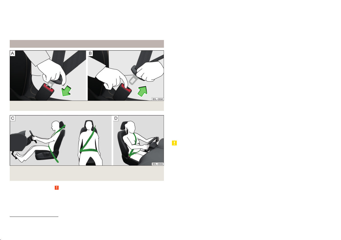
Fastening and unfastening seat belts
Fig. 5 Fastening/unfastening the seat belt
Fig. 6 Routing of belt webbing over the shoulders and the lap belt/Rout-
ing of belt webbing for an expectant mother
Use the lock tongue to slowly pull the webbing over your chest and pelvis.
›
Insert the lock tongue into the belt buckle for the seat » Fig. 5 - until it
›
audibly clicks into place.
Pull on the belt to check that it has engaged correctly in the lock.
›
A plastic knob in the belt webbing holds the belt tongue in a position which is
easy to get hold of.
It is important that the belt is properly routed to ensure seat belts offer the
maximum protection.
The shoulder part of the seat belt must never run across the neck but must
roughly run over the middle of the shoulder and fit snugly against the chest.
The lap part of the belt must run across the pelvis, must not be positioned
across the stomach and must always fit snugly » Fig. 6 - .
Expectant women must also always wear a seat belt. This is the only way of
ensuring optimal protection for the unborn child.
With pregnant women, the lap part of the belt must be positioned as low as
possible on the pelvis to avoid exerting any pressure on the lower abdomen » Fig. 6 - .
Release
Release the seat belt only when the vehicle is stationary.
Press the red button in the belt buckle » Fig. 5 - ; the lock tongue pops out.
›
Manually guide the belt back so that it is easier to fully roll up the webbing,
›
the seat belt does not twist.
CAUTION
When releasing the seatbelt ensure that the tongue of the lock does not damage the door trim or other parts of the interior.
Read and observe on page 12 first.
Fasten
Correctly adjust the front seat and head restraint1) before fastening the seat
›
belt » page 9.
1)
Not valid for sports seat.
14
Safety
Page 18
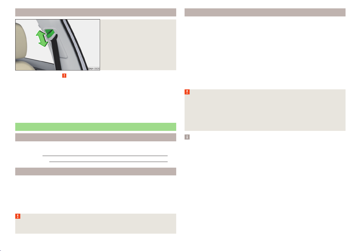
Belt height adjustment on the front seats
Fig. 7
Front seat: Seat belt height adjuster
Read and observe on page 12 first.
The seat belt height adjuster makes it possible to adjust the routing of the
front seat belts in the area of the shoulder to the body size.
Press the seat belt height adjuster and move up or down in the desired di-
›
rection » Fig. 7.
Then pull firmly on the belt to ensure that the seat belt height adjuster has
›
correctly locked in place.
Inertia reels and belt tensioners
Introduction
This chapter contains information on the following subjects:
Inertia reels
Belt tensioners
Inertia reels
Each seat belt is equipped with an inertia reel.
When pulling slowly on the seat belt, the belt can move freely. When pulling
sharply on the seat belt, the movement is locked by the inertia reel.
The belts also lock when full braking, when the car accelerates, when driving
downhill and when cornering.
WARNING
If the seat belt does not lock when pulling sharply on it, have it inspected
immediately by a specialist garage.
Belt tensioners
Safety for the driver and front passenger wearing their seat belts is enhanced
by the belt tensioners fitted to the inertia reels of the front three-point seat
belts.
The three-point seat belts are automatically tensioned in the event of a frontal
collision of a certain severity. The belt tensioners can also be deployed if the
seat belts are not fastened.
The seat belts are automatically tensioned in the event of a collision of a certain severity.
Belt tensioners are not activated in the event of minor frontal collisions, side
and rear-end collisions, in the case of a rollover and also not in accidents in
which no major forces are produced from the front.
WARNING
■
Any work on the belt tensioner system including removal and installation
of system components because of other repair work, must only be carried
out by a specialist garage.
■
The protective function of the system is only adequate for a single accident. If the belt tensioners have been deployed, it is then necessary to replace the entire system.
Note
■
Smoke is generated when the belt tensioners are deployed. This is not an in-
dication of a fire in the vehicle.
■
15
When disposing of the vehicle or parts of the belt tensioner system, it is im-
portant to comply with national legal requirements. ŠKODA service partners
15
are familiar with these regulations and will be able to provide you with detailed information.
Seat belts
15
Page 19

Airbag system
Description of the airbag system
Introduction
This chapter contains information on the following subjects:
System description 16
Airbag deployment 16
WARNING
■
An airbag can only offer you optimal protection in combination with a
fastened seat belt.
■
The airbag is not a substitute for the seat belt, but instead forms part of
the complete passive vehicle safety concept.
■
To ensure passengers are protected with the greatest possible effect
when the airbag is deployed, the front seats must be correctly adjusted to
match the body size » page 9, Correct and safe seated position.
■
If you do not fasten the seat belts when driving, lean too far forward or
adopt an incorrect seated position, you are exposing yourself to increased
risk of injury in the event of an accident.
WARNING
Information on the use of the airbag system
■
If there is a fault, the airbag system must be checked by a specialist garage immediately. Otherwise, there is a risk of the airbag not being activated in the event of an accident.
■
No modifications of any kind may be made to parts of the airbag system.
■
Any work on the airbag system, including the installation and removal of
system components due to other repair work (e.g. removal of the steering
wheel), must only be carried out by a specialist garage.
■
Never make any changes to the front bumper or the bodywork.
■
It is prohibited to manipulate individual parts of the airbag system, as this
might result in the airbag being deployed.
■
The protective function of the airbag system is sufficient for only one accident. The airbag system must then be replaced if the airbag has been deployed.
System description
Read and observe on page 16 first.
The functional status of the airbag system is indicated by the indicator light
in the instrument cluster » page 39.
When the airbags are deployed, they fill with gas and inflate.
A grey white or red, non-harmful gas is released when the airbag is inflated.
This is perfectly normal and is not an indication of a fire in the vehicle.
Depending on the vehicle equipment, the airbag system consists of the
following modules.
Electronic control unit.
›
Front airbag for the driver and the front passenger » page 17.
›
Side airbags » page 18.
›
Head airbags » page 19.
›
Airbag warning light in the instrument cluster » page 39.
›
Key switch for the front passenger airbag » page 20.
›
Warning light for the front passenger airbag deactivation/activation in the
›
middle of the dash panel » page 20.
Note
■
The airbag system needs no maintenance during its working life.
■
If you sell your vehicle, provide the complete vehicle documentation to the
new owner. Please note that the information relating to the possibility of deactivating the front passenger airbag must be included!
■
When disposing of vehicle or parts of the airbag system, it is important to
comply with the national legal requirements.
Airbag deployment
Read and observe
The airbags inflate in fractions of a second and at a high speed in order to be
able to offer additional protection in the event of an accident.
The airbag system is only functional when the ignition is switched on.
In certain accident situations, the several airbags may be deployed simultane-
ously.
The airbags are not deployed in the case of minor frontal and side collisions,
rear-end collisions, tilting of the vehicle and vehicle rollover.
on page 16 first.
16
Safety
Page 20
Deployment factors
It is not possible to generally determine which deployment conditions apply to
the airbag system in every situation. An important role is played by factors
such as the type of object that the vehicle hits (hard/soft), the impact angle,
vehicle speed etc.
A decisive factor for the deployment of the airbags is the deceleration which
occurs. The control unit analyses the nature of the collision and activates the
relevant restraint system.
If the vehicle deceleration which occurs and is measured during the collision
remains below the prescribed reference values specified in the control unit,
the airbags are not deployed although the vehicle may well suffer severe damage to the bodywork as a consequence of the accident.
The following airbags will be deployed in the event of a severe frontal
collision.
Driver’s front airbag.
›
Front passenger airbag.
›
The following airbags will be deployed in the event of a severe side collision.
Front side airbag on the side of the accident.
›
Head airbags on the side of the accident.
›
When an airbag is deployed, the following events occur.
The interior lighting illuminates (if the switch for the interior light is in the
›
door contact position).
The hazard warning lights are switched on.
›
All the doors are unlocked.
›
The fuel supply to the engine is interrupted.
›
Airbag overview
Introduction
This chapter contains information on the following subjects:
Front airbags
Side airbags 18
Head airbags 19
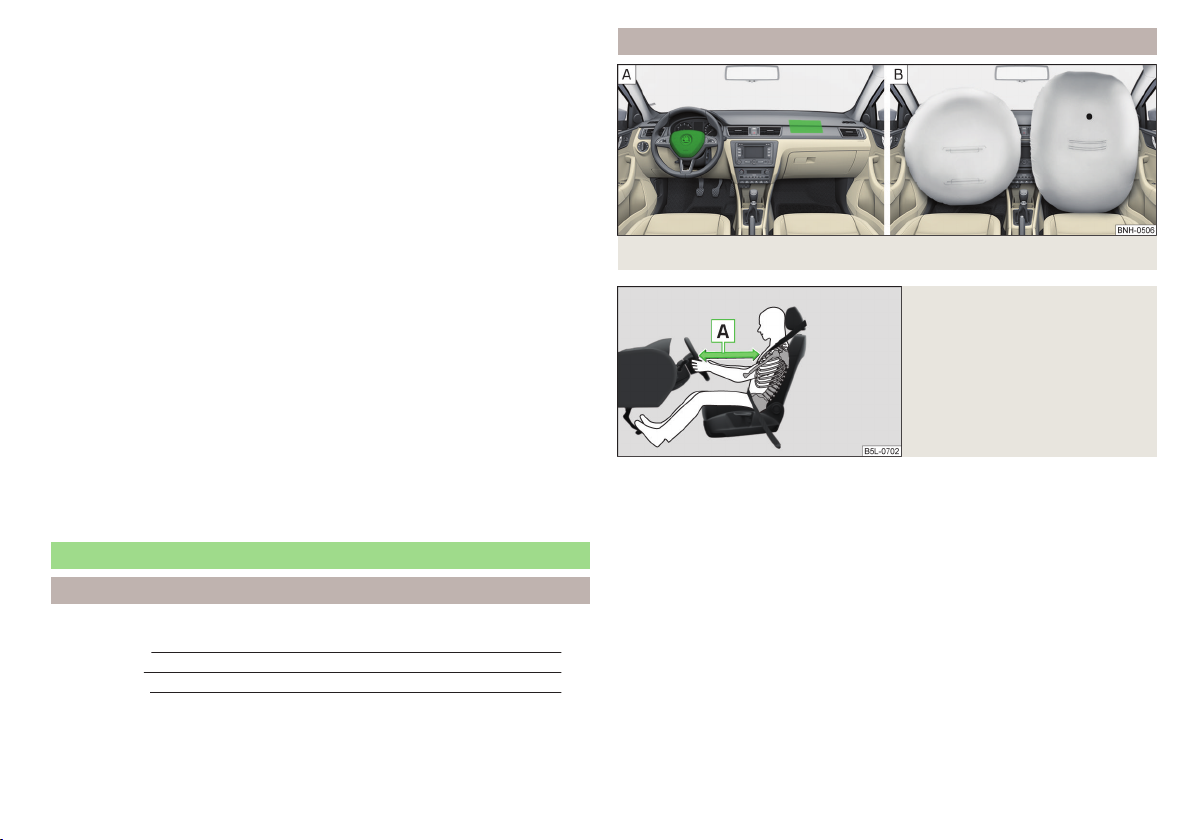
Front airbags
Fig. 8 Locations of the airbags / gas filled airbags
Fig. 9
Safe distance to steering wheel
In the event of a severe frontal collision, the front airbag system offers additional protection for the head and chest area of the driver and front passenger.
The driver's front airbag is located in the steering wheel, the front passenger
airbag is located in the instrument panel above the glove compartment » Fig. 8
- .
The airbags inflate in front of the driver and front passenger when they are
deployed » Fig. 8 - . The forward movement of the driver and of the front
passenger is cushioned when they make contact with the fully inflated airbag
and the risk of injury to head and chest is thus reduced.
17
Airbag system
17
Page 21
WARNING
Information on correct seated position
■
It is important that the driver and front passenger maintain a distance of
at least 25 cm to the steering wheel or dashboard A » Fig. 9. Not maintaining this minimum distance will mean that the airbag system will not be able
to properly protect you – hazard! The front seats and the head restraints
must always also be correctly adjusted to match the body size of the occupant.
■
The airbag develops enormous forces when triggered, which can lead to
injuries if the sitting position or seated position is not correct.
■
There must not by any further persons, animals or objects positioned between the front seated occupants and the deployment area of the airbag.
WARNING
Front airbag and transporting children
■
Never transport children on the front seat of a vehicle without using a
proper restraint system. If airbags are deployed in the event of an accident,
the child might suffer severe or even fatal injuries!
■
The front passenger airbag must be deactivated if using a rear-facing
child seat on the front passenger seat » page 20, Deactivating airbags. If
this is not done, there is a risk of the child suffering severe or even fatal
injuries if the front passenger airbag is deployed. When transporting a child
on the front passenger seat, pay attention to any relevant national regulations regarding the use of child safety seats.
WARNING
General information
■
The steering wheel and the surface of the airbag module in the dash panel on the passenger side must not have stickers attached, be covered or
modified in any other way. These parts should only be cleaned with a cloth
that is dry or has been moistened with water. No objects such as cup holders, mobile phone mounts, etc. must be attached to the covers of the airbag modules or be located within their immediate vicinity.
■
Never place objects on the surface of the front passenger airbag module
in the dash panel.
Note
■
In vehicles with head airbags, the lettering can be seen on the steering
wheel.
■
In vehicles with front passenger airbags, the lettering
is located on the
dash panel on the passenger side.
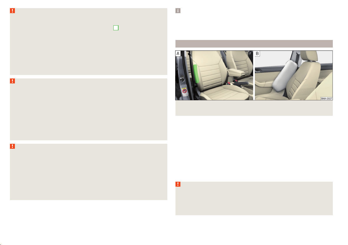
Side airbags
Fig. 10 Location of the side airbag in the driver's seat/gas-filled side airbag
In the event of severe side collisions, the side airbag system provides additional protection for the upper body (chest, stomach and pelvis) of passengers in
the vehicle.
The side airbags are housed in the upholstery of the front seat backrests » Fig. 10 - .
When the side airbags » Fig. 10 - are deployed, the head airbag and belt tensioner are also automatically deployed on the relevant side.
The load of the occupants is cushioned when plunging into the fully inflated
airbag and the risk of injury to the entire upper body (chest, stomach and pelvis) is reduced on the side facing the door.
WARNING
Information on correct seated position
■
Your head should never be positioned in the deployment area of the side
airbag. You might suffer severe injuries in the event of an accident. This applies in particular to children who are transported without using a suitable
child safety seat » page 24, Child safety and side airbag.
18
Safety
Page 22
WARNING (Continued)
■
There must not be any further persons, animals or objects positioned between the occupants and the deployment area of the airbag. No accessories, such as cup holders, should be attached to the doors.
■
If children adopt an incorrect seated position when travelling, they may
be exposed to an increased risk of injury in the event of an accident. This
can result in serious injuries » page 22, Child seat.
WARNING
■
Only hang light items of clothing on the hooks fitted in the vehicle. Never
leave any heavy or sharp-edged objects in the pockets of the items of
clothing.
■
Ensure that there are no excessive forces, such as violent knocks, kicks
etc., impact on the backrests of the seats otherwise the system may be
damaged. The side airbags would not be deployed in such a case!
■
Any seat or protective covers which you fit to the driver or front passenger seats must only be of the type expressly authorized by ŠKODA. In view
of the fact that the airbag inflates out of the backrest of the seat, use of
non-approved seat or protective covers would considerably impair the protective function of the side airbag.
■
Any damage to the original seat covers in the area of the side airbag module must be repaired immediately by a specialist garage.
■
The airbag modules in the front seats must not display any damage,
cracks or deep scratches. It is not permissible to use force in order to open
the modules.
Note
In vehicles with side airbags a label with the lettering is located on the
front seat backrests.
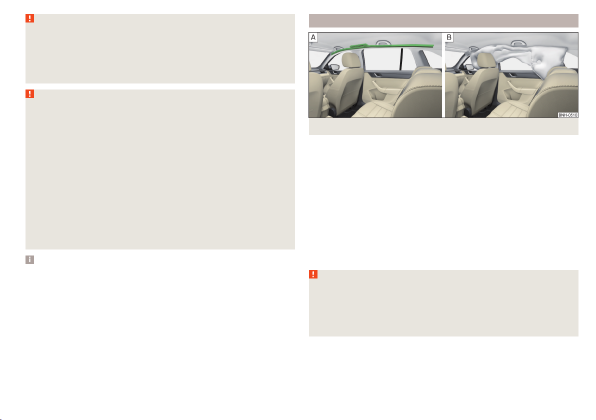
Head airbags
Fig. 11 Location of the head airbag/gas-filled head airbag
In the event of a severe side collision, the head airbag system offers additional
protection for the head and neck area of passengers.
The head airbags are positioned above the doors on both sides of the vehicle
interior » Fig. 11 - .
In the event of a side collision the head airbag is deployed together with the
relevant side airbag and the front seat belt tensioner on the side of the car on
which the accident occurs.
When deployed, the airbag covers the window area of the front and rear doors,
as well as the area of the door pillar » Fig. 11 - .
Head impact with interior parts is reduced by the inflated head airbag. The reduction in any impact to the head and the resultant minimizing of any movements of the head additionally reduce the risk of injuries to the neck area.
WARNING
■
There must not be any objects in the deployment area of the head air-
bags which might prevent the airbags from inflating properly.
■
Only hang light items of clothing on the hooks fitted in the vehicle. Never
leave any heavy or sharp-edged objects in the pockets of the items of
clothing. Additionally, clothes hangers must not be used to hang up items
of clothing.
Airbag system
19
Page 23
WARNING (Continued)
■
The installation of impermissible accessories in the vicinity of the head
airbags can considerably impair the protection offered by the head airbag in
the event of it being deployed. When the deployed head airbag is inflated,
parts of the accessories fitted could be thrown into the interior of the car
and injure the occupants » page 128.
■
The sun visors must not be swivelled towards the side windows in the
deployment area of the head airbags if any objects, such as ball-point pens,
etc. are attached to them. This might result in injuries to the occupants if
the head airbag is deployed.
■
There must not be any further persons, animals or objects positioned between the seated occupants and the deployment area of the airbag. In addition, none of the occupants should lean their head out of the window
when driving, or extend their arms and hands out of the window.
Note
In vehicles with head airbags, the lettering can be seen on the B column
cladding.
Deactivating airbags
Introduction
This chapter contains information on the following subjects:
Deactivating airbags 20
Deactivating the front passenger airbag 20
Deactivating airbags
Deactivating an airbag should be considered in cases such as the ones below.
If using a rear-facing child seat on the front passenger seat (due to different
›
legal regulations, the airbag must be deactivated if using a forwards-facing
child seat in some countries) » page 22, Transporting children safely.
If it is not possible to maintain a distance of at least 25 cm between the mid-
›
dle of the steering wheel and chest, despite the driver's seat being correctly
adjusted.
If special attachments are required in the area of the steering wheel because
›
of a physical disability.
If different seats have been fitted (e.g. orthopaedic seats without side air-
›
bags).
The front passenger airbag can be switched off with the key-operated
switch » page 20.
We recommend that you ask a ŠKODA service partner to deactivate any other
airbags.
Monitoring the airbag system
The operational capability of the airbag system is monitored electronically, including when one of the airbags is switched off.
Airbag deactivated using diagnostic equipment
The warning light illuminates for approximately 4 seconds after the igni-
›
tion is switched on and then flashes again for approximately 12 seconds.
Front passenger airbag deactivated using the key switch in the storage compartment
The warning light lights up for approximately 3 seconds after the ignition
›
is switched on.
The warning light
›
has been switched on.
Note
■
The national regulations for switching off airbags must be observed.
■
A ŠKODA service partner will be able to inform you which, if any, of your vehi-
cle's airbags can or must be deactivated.
» Fig. 12 on page 20 - comes on after the ignition
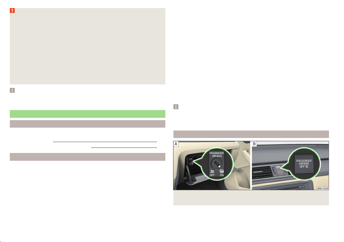
Deactivating the front passenger airbag
Fig. 12 Key-operated switch for the front passenger airbag / warning
light for front seat passenger airbag deactivation
Only the front passenger airbag is deactivated with the key switch.
20
Safety
Page 24

Switching off
Switch off the ignition.
›
Open the storage box on the front passenger's side.
›
Fold the key bit out completely for the radio key » .
›
Carefully insert the key into the key slot in the key switch as far as the stop.
›
Use the key to turn the slot of the key switch carefully into the position
›
» Fig. 12 - .
Pull the key out of the slot in the key switch » .
›
Close the storage box on the front passenger's side.
›
Check that the warning light
›
lights up after the ignition is switched on.
Switching on
Switch off the ignition.
›
Open the storage box on the front passenger's side.
›
Fold the key bit out completely for the radio key » .
›
Carefully insert the key into the key slot in the key switch as far as the stop.
›
Use the key to turn the slot of the key switch carefully into the position
›
» Fig. 12 - .
Pull the key out of the slot in the key switch » .
›
Close the storage box on the front passenger's side.
›
Check that the warning light
›
does not illuminate after the ignition is switched on.
WARNING
■
The driver is responsible for whether the airbag is switched on or switch-
ed off.
■
Only switch off the airbag when the ignition is switched off! Otherwise a
fault can occur in the system for deactivating the airbag.
■
If the
be deployed in an accident! Have the airbag system checked by a specialist
garage immediately.
■
The key cannot be inserted in the key switch while driving.
■
Shocks can cause the key to turn in the slot and trigger the airbag!
■
The airbag could be triggered unexpectedly in an accident - it may result
in injury or death!
warning light is flashing, the front passenger airbag will not
1)under the text
under the text
» Fig. 12-
» Fig. 12 -
CAUTION
An insufficiently folded out key bit can damage the key switch!
1)
The warning light comes on for a few seconds after the ignition is switched on, goes out for about
1 second and then comes on again.
Airbag system
21
Page 25

Transporting children safely
Child seat
Introduction
This chapter contains information on the following subjects:
Use of a child seat on the front passenger seat 23
Use of the child seat in the front passenger seat 24
Child safety and side airbag 24
Classification of child seats 24
Use of child seats fastened with a seat belt 24
Children are generally safer on the rear seats than on the front passenger
seat.
In contrast to adults, the muscles and bone structure of children are not yet
fully developed. Thus children are exposed to increased risk of injury.
Children should be transported in accordance with the relevant statutory provisions.
Child seats complying with the ECE-R 44 standard must be used. ECE-R stands
for: Economic Commission for Europe – Regulation.
Child seats that comply with the ECE-R 44 standard have a test seal that cannot be removed: a large E within a circle with the test number below.
WARNING
■
The national legal requirements must be observed when using child
seats.
■
One should never carry children, and also not babies! - on one's lap.
■
Never leave children unattended in the vehicle. Certain outside climatic
conditions can cause life-threatening temperatures in the vehicle.
■
The child must be secured in the vehicle during the entire journey! Otherwise, the child would be thrown through the vehicle in the event of an accident, causing fatal injuries to both the child and other occupants.
WARNING (Continued)
■
Children are exposed to an increased risk of injury in the event of an accident if they lean forward or adopt an incorrect seated position when the
vehicle is moving. This particularly applies to children who are transported
on the front passenger seat as they can suffer severe, or even fatal injuries
if the airbag system is deployed!
■
Pay particular attention to the information provided by the manufacturer
of the child safety seat regarding the correct routing of the belt. Seat belts
which are not correctly adjusted can themselves cause injuries even in minor accidents.
■
Safety belts must be checked to ensure that they are running properly.
One should also ensure that the belt is not damaged by sharp-edged fittings.
■
The front passenger airbag must be deactivated if using a rear-facing
child seat on the front passenger seat. Further information » page 23, Use
of a child seat on the front passenger seat.
CAUTION
■
When installing a child seat in which the child faces forward, adjust the head
restraints so that they are as high as possible.
■
If the head restraints still prevent the child seat from being installed, even in
the highest position, you will need to remove them » page 70. After removing the child seat, reinstall the head restraints.
Note
We recommend that you use child seats from ŠKODA Original Accessories.
These child seats were developed and also tested for use in ŠKODA vehicles.
They meet the ECE-R 44 standard.
22
Safety
Page 26
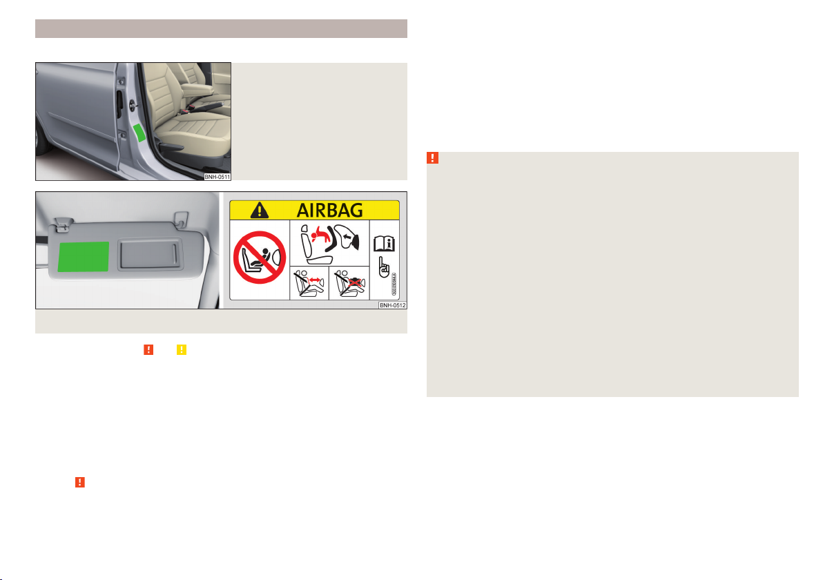
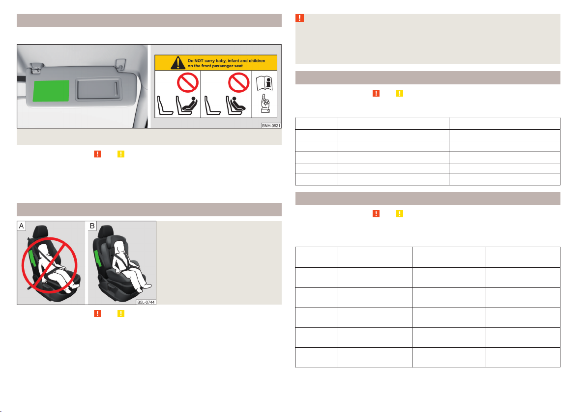
Use of a child seat on the front passenger seat
Does not apply to Taiwan
Fig. 13
Sticker on the B column on the
front passenger side
Fig. 14
Front passenger sun visor / label
Read and observe and on page 22 first.
Never use a rearward-facing child restraint system on a seat which is protected by an active airbag installed in front of it. This could cause serious injury
to the child, even death.
For safety reasons, we recommend that you install child seats on the rear
seats whenever possible.
The following instructions must be followed when using a child seat on the
front passenger seat.
The front passenger airbag must be deactivated if using a rear-facing child
›
seat » .
If possible, adjust the front passenger seat backrest so that it is as vertical,
›
so as to ensure secure contact between the passenger seat backrest and the
back of the child seat.
If possible, move the front passenger seat backwards so that there is no con-
›
tact between the front passenger seat and the child seat behind it.
With child safety seats in groups 2 or 3, make sure that the loop-around fit-
›
tings attached to the child seat headrest is positioned in front of or at the
same height as the loop-around fittings on the B pillar on the passenger side.
Set the height-adjustable front passenger seat as high up as possible.
›
Set the front passenger seat belt as high up as possible.
›
Place and fasten the child seat on the seat and the child in the child seat ac-
›
cording to the specifications in the manufacturer's user manual of the child
seat .
WARNING
■
The front passenger airbag must be deactivated if using a rear-facing
child seat on the front passenger seat » page 20, Deactivating airbags.
■
Never use a rear-facing child seat on the front passenger seat if the passenger airbag is activated. This child safety seat is positioned in the deployment area of the front passenger airbag. The airbag may cause the child severe, or even fatal injuries, in the event of it being deployed.
■
This fact is also indicated by the label that can be found in one of the following locations.
■
On the B-column on the front passenger side » Fig. 13. The sticker is
visible upon opening the front passenger door.
■
On the front passenger's sun visor. In some countries, the sticker is lo-
cated on the front seat passenger's sun visor » Fig. 14.
■
With child safety seats in groups 2 or 3, make sure that the loop-around
fittings attached to the child seat headrest is positioned in front of or at
the same height as the loop-around fittings on the B pillar on the passenger side.
■
As soon as the rear-facing child seat is no longer being used on the passenger seat, the front passenger airbag should be re-activated again.
Transporting children safely
23
Page 27
Use of the child seat in the front passenger seat
Applies to Taiwan
Fig. 15 Front passenger sun visor / label
Read and observe and on page 22 first.
No babies, infants or children are to be carried on the passenger seat.
This fact is also indicated by the label that can be found on the passenger's
sun visor » Fig. 15.
Child safety and side airbag
Fig. 16
Incorrect seated position of a
child who is not properly secured
– risk from the side airbag/Child
properly protected by safety seat
Read and observe
The child must not be positioned in the deployment area of the side airbag » Fig. 16 - .
There must be sufficient room between the child and the deployment area of
the side airbag to ensure that the airbag can provide as much protection as
possible » Fig. 16 - .
and on page 22 first.
WARNING
■
Children must never be seated with their head in the deployment area of
the side airbag – risk of injury!
■
Do not place any objects within the deployment area of the side airbags –
risk of injury!
Classification of child seats
Read and observe and on page 22 first.
Classification of child seats according to the ECE-R 44 standard.
Group Weight of the child Approximate age
0 up to 10 kg up to 9 months
0+ up to 13 kg up to 18 months
1 9 - 18 kg up to 4 years
2 15 - 25 kg up to 7 years
3 22 - 36 kg over 7 years
Use of child seats fastened with a seat belt
Read and observe
Overview of the usability of child seats fastened with a seat belt on each of
the seats in accordance with the ECE-R 16 standard.
Group
0
up to 10 kg
0+
up to 13 kg
1
9 - 18 kg
2
15 - 25 kg
3
22 - 36 kg
Front passenger
and on page 22 first.
seat
U U U
U U U
U U U
U U U
U U U
Rear seats
external
Rear seat
Centre
24
Safety
Page 28
“Universal” child seat category - a child seat designed to be attached to
U represents a system for a fast and secure child seat mounting.
the seat using the seat belt.
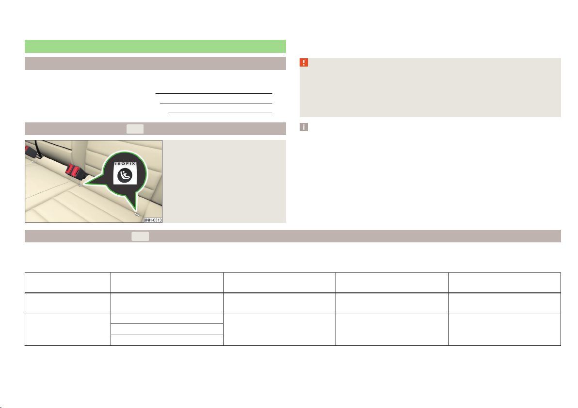
Fastening systems
Introduction
This chapter contains information on the following subjects:
Attachment points of the
Use of child seats with the
Attachment points of the
-system 25
-system 25
-system 26
There are two locking eyes between the rear exterior seats for fixing the child
seat in place, using the
the
logo » Fig. 17.
WARNING
■
Always refer to the instructions from the manufacturer of the child seat
when installing and removing a child seat with the -system.
■
Never attach other child seats, belts or objects to the attachment points
eyes intended for the installation of a child seat with the
of death!
-system. The places are marked with labels with
-system – risk
Attachment points of the
-system
Fig. 17
Labels on the ISOFIX system
Use of child seats with the -system
Overview of the usefulness of child seats fastened with the -system on
each of the seats in accordance with the ECE-R 16 standard.
Group
0
up to 10 kg
0+
up to 13 kg
Size class of
the child seat
a)
E X IL-SU X
E
C
Front passenger seat Outer rear seats Rear seat middle
Note
■
A child seat fitted with the -system can only be mounted in a vehicle fit-
ted with an -system if the child seat has been approved for this type of vehicle. Further information is available from a ŠKODA Partner.
■
Child seats with the
cessories.
X IL-SU XD
-system can be purchased from ŠKODA Original Ac-
Transporting children safely
25
Page 29
Group
Size class of
the child seat
a)
D
1
9 - 18 kg
C
B
B1
A
2
15 - 25 kg
3
22 - 36 kg
a)
The size category is shown on the label attached to the child seat.
The seat is suited for installation of a -child seat with the “Semi-
IL-SU
X IL-SU X
X IL-SU X
Universal” approval. The “Semi-Universal” category means that the child
seat with the
-system is approved for your vehicle. Observe the list
of vehicles that comes with the child seat.
-system
-child seat with the ap-
-system belt.
The seat is suitable for the installation of a
IUF
proval “Universal” and attachment with the
The seat is not fitted with
X
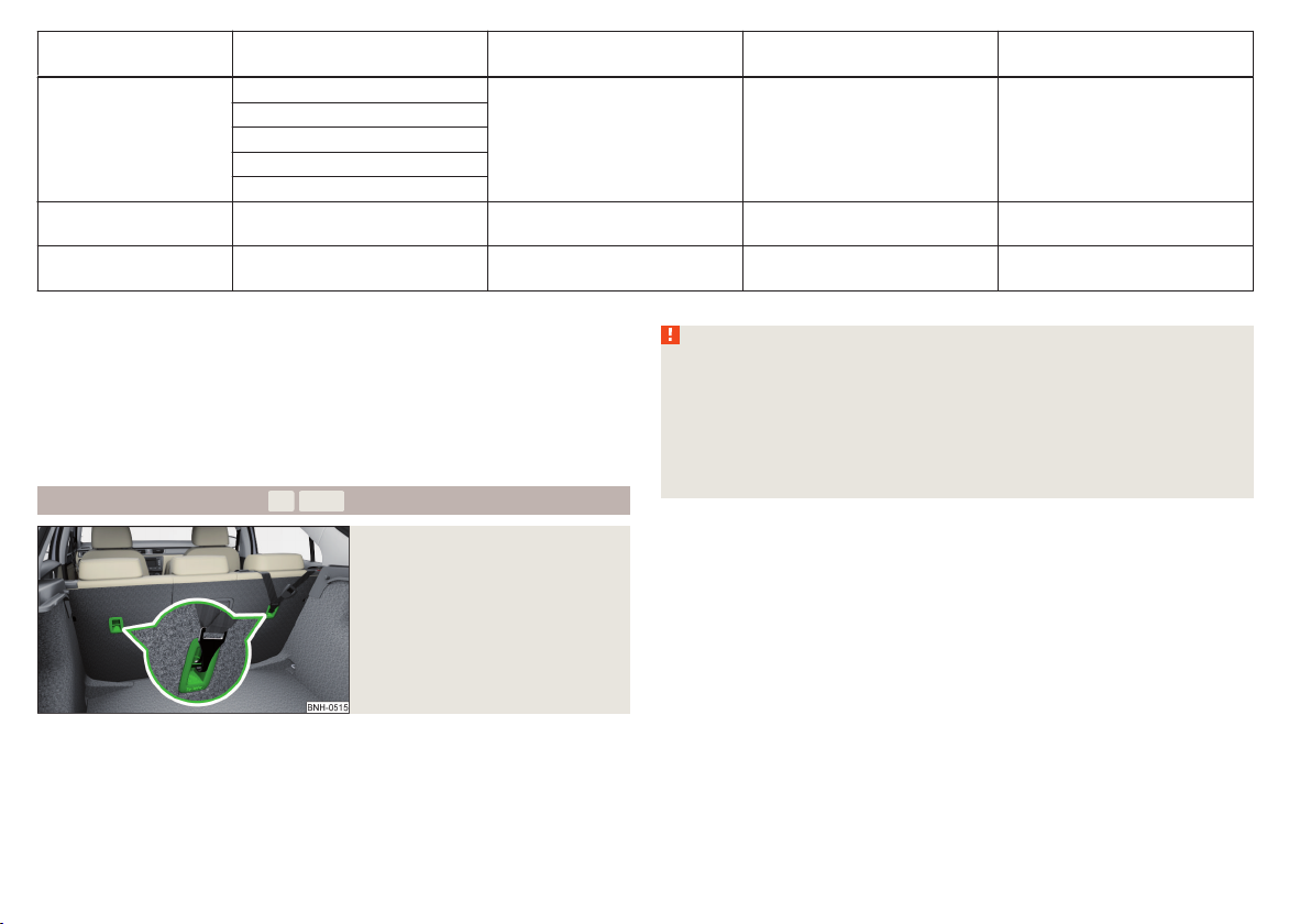
Attachment points of the
-system attachment points.
Fig. 18
Anchor eyelets on the TOP
TETHER system
Front passenger seat Outer rear seats Rear seat middle
X
IL-SU
IUF
X
WARNING
■
Always refer to the instructions from the manufacturer of the child seat
when installing and removing a child seat with the -system.
■
Only use child seats with the
-system on the seats with the lock-
ing eyes.
■
Only ever attach one belt from the child seat to a locking eye.
■
On no account should you equip your vehicle, e.g. mount screws or other
anchorage points.
represents a fastening system, which restricts movements of the up-
per part of the child seat.
The anchor eyelets for attaching the belt for a child seat with the
tem are located on the rear side of the outer rear seat backrests » Fig. 18.
26
Safety
-sys-
Page 30

Transporting children safely
27
Page 31
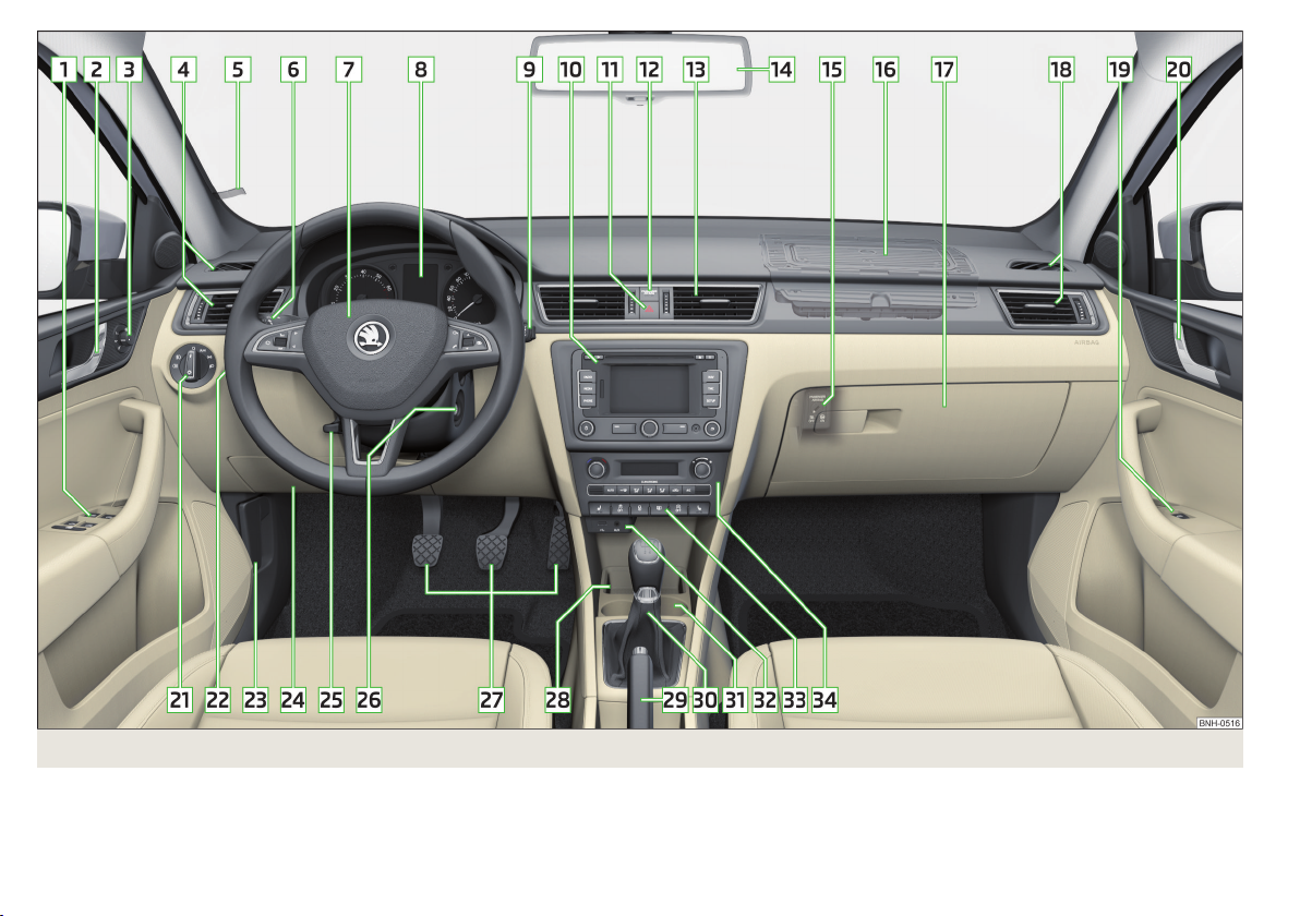
Fig. 19 Cockpit
28
Using the system
Page 32

Using the system
Cockpit
Overview
1
Electrical power windows 56
2
Door opening lever 51
3
Electric exterior mirror adjustment 68
4
Air outlet vents 90
5
Parking ticket holder 74
6
Operating lever:
Turn signal light, headlight and parking light, headlight
›
flasher 60
Speed regulating system 115
›
7
Steering wheel:
With horn
›
With driver’s front airbag 17
›
with push-buttons for radio, navigation system and mobile
›
phone 94
With buttons for the operation of the information system 41
›
8
Instrument cluster 30
9
Operating lever:
Windscreen wiper and wash system 66
›
Information system 41
›
10
Depending on equipment fitted:
Radio
›
Navigation system
›
11
Button for hazard warning light system 62
12
Warning light for the deactivated front seat passenger airbag 20
13
Air outlets in the central part of the dash panel 90
14
Interior rear-view mirror 67
15
Key switch for switching off the passenger airbag (in front passenger storage compartment) 20
16
Front passenger airbag 17
17
Storage compartment on the front passenger side 78
18
Air outlet vents 90
19
Power window in the front passenger door 55
20
Door opening lever 51
21
Light switch 58
22
Headlight range control (in the dashboard) 59
23
Bonnet release lever 142
24
Fuse box in the dashboard 173
25
Lever for adjusting the steering wheel 10
26
Ignition lock 105
27
Pedals 108
28
Storage compartment 74
29
Handbrake lever 107
30
Depending on equipment fitted:
Gear shift lever (manual gearbox) 108
›
Selector lever (automatic gearbox) 109
›
31
Depending on equipment fitted:
Cup holder 74
›
Multimedia holder 77
›
Ashtrays 76
›
32
Multi-Device Interface (MDI) input 101
33
Bar with keys depending on the equipment fitted:
Seat heater on the front left seat 71
›
Electronic Stability Control (ESC) 113
›
Central locking system 52
›
Rear window heater 64
›
START - STOP 116
›
Seat heater on the front right seat 71
›
34
Depending on equipment fitted:
Operating controls for the heating 91
›
Operating controls for the air conditioning system
›
Operating controls for Climatronic
›
Note
The arrangement of the controls right-hand drive models may differ from the
layout shown in » Fig. 19. The symbols on the controls and switches are the
same as for left-hand drive models.
91
92
Cockpit
29
Page 33

Instruments and Indicator Lights
Instrument cluster
Introduction
This chapter contains information on the following subjects:
Overview 30
Revolution counter 31
Display 31
Speedometer 31
Coolant temperature gauge 32
Fuel gauge 32
Counter for distance driven 33
33
Display of the second speed 33
Auto Check Control 33
The instrument cluster gives the driver basic information such as the current
speed, engine speed, the state of some vehicle systems and the like.
Fault display
If there is a fault in the instrument cluster, the Error message will appear in
the display.
Seek help from a specialist garage.
WARNING
Concentrate fully at all times on your driving! As the driver you are fully responsible for road safety.
Note
When the ignition is on, the instrument cluster is illuminated1). The brightness
level is automatically adjusted depending on the ambient lighting.
Overview
Fig. 20 Instrument cluster - Version 1
Fig. 21 Instrument cluster - Version 2
Read and observe on page 30 first.
1
Engine revolutions counter » page 31
with warning lights » page 34
›
2
Display » page 31
1)
Applies to cars with the instrument cluster - Version 1.
30
Using the system
Page 34

3
Speedometer » page 31
with warning lights » page 34
›
4
Button for display mode:
Time settings » page 33
›
Enable/disable the display of the second speed1) » page 33
›
Service intervals - Display of the number of days and kilometres remain-
›
ing until the next service1) » page 47
5
Button for:
Reset counter for distance travelled (trip) » page 33
›
Setting the time
›
enable / disable the mode selected by means of the 4 key
›
6
Coolant temperature gauge2) » page 32
7
Fuel gauge2) » page 32
Revolution counter
Read and observe on page 30 first.
The tachometer 1 » Fig. 20 on page 30 or » Fig. 21 on page 30 shows the actual engine speed per minute.
The beginning of the red scale range of the tachometer indicates the maximum permitted engine speed of a driven-in and operating warm engine.
You should shift into the next highest gear before the red scale of the revolution counter is reached, or select mode D on the automatic gearbox.
The gear recommendation is important to note in order to maintain the optimum engine speed » page 43.
CAUTION
The pointer of the tachometer must reach the red area for only a short time there is a risk of engine damage!
Display
Fig. 22
Display types
Read and observe on page 30 first.
Display types » Fig. 22
MAXI DOT display.
Segment display
The following information will be displayed.
Fuel gauge3) » page 32
›
Distance travelled » page 33
›
Time » page 33
›
Details of the information system » page 41
›
Details of the service interval display » page 47
›
CAUTION
Pull out the ignition key if coming in contact with the display (e.g. when cleaning) to prevent any possible damage.
Speedometer
Read and observe on page 30 first.
The speedometer 3 » Fig. 20 on page 30or » Fig. 21 on page 30 displays the
current speed.
1)
Applies to cars with the instrument cluster - Version 2.
2)
Applies to cars with the instrument cluster - Version 1.
3)
Applies only to the segment display (instrument cluster - version 2).
Instruments and Indicator Lights
31
Page 35

Warning at excessive speeds
An audible warning signal will sound when the vehicle speed exceeds 120 km/
h1). The audible warning signal is switched off when the vehicle speed falls below 120 km/h.
CAUTION
■
Additional headlights and other attached components in front of the air inlet
impair the cooling efficiency of the coolant.
■
Never cover the radiator - there is a risk of the engine overheating.
Coolant temperature gauge
Fig. 23
Coolant temperature gauge
Read and observe on page 30 first.
Applies to cars with the instrument cluster - Version 1 » Fig. 20 on page 30.
The display » Fig. 23 provides information on the engine coolant temperature.
The display only works if the ignition is switched on.
In vehicles with the instrument cluster - version 2, » Fig. 21 on page 30 the
coolant temperature is indicated only by one of the warning lights » page 36,
Coolant coming on or going off.
Cold range
If the pointer is still in the left area of the scale, this indicates that the engine
has not yet reached its operating temperature. Avoid high speeds, full throttle
and high engine loads. This prevents possible damage to the engine.
The operating range
The engine has reached its operating temperature as soon as the pointer
moves into the middle of the scale
tures or heavy engine loads, the pointer may move even further to the right.
High temperature range
If the pointer reaches the red area of the scale, the coolant temperature is too
high. Further information » page 36, Coolant.
A
» Fig. 23. At very high ambient tempera-
Fuel gauge
Fig. 24 Fuel gauge
Read and observe on page 30 first.
The display provides information on the fuel level in the container.
Fuel gauge types » Fig. 24
Display in the instrument cluster - Version 1
In the display of the instrument cluster - Version 2
The display only works if the ignition is switched on.
The fuel tank has a capacity of about 55 litres.
The warning light lights up when the amount of fuel reaches the reserve zone
» page 39.
The reserve zone is indicated by the red area of the scale » Fig. 24 - or by
displaying only the last two segments of the scale » Fig. 24 - in the magnifying glass.
1)
This function only applies to certain countries.
32
Using the system
Page 36

CAUTION
Never drive until the fuel tank is completely empty! The irregular supply of fuel
can cause misfiring. This can result in considerable damage to parts of the engine and the exhaust system.
Note
■
After filling up, it can occur that during dynamic driving (e.g. numerous
curves, braking, driving downhill and climbing a steep hill) the fuel gauge indicates approx. a fraction less. When stopping or during less dynamic driving, the
fuel gauge displays the correct fuel level again. This is not a fault.
■
The arrow next to the icon within the fuel gauge displays the installation
location of the fuel filler on the right-hand side of the vehicle.
Counter for distance driven
Fig. 25
Display: MAXI DOT display / Segment display
Read and observe on page 30 first.
Display » Fig. 25
A
Counter for distance travelled (trip)
B
Odometer
Counter for distance travelled (trip)
The daily trip counter shows the distance driven since the time the counter
was last reset - in steps of 0.1 km.
Reset counter for distance travelled (trip)
Press and hold the 5 » Fig. 20 on page 30 or » Fig. 21 on page 30 button.
›
Odometer
The odometer indicates the total distance which the vehicle has been driven.
Note
If the second speed display is enabled on vehicles with a segment display, this
speed will be shown instead of the odometer.
Read and observe on page 30 first.
Use buttons 4 and 5 » Fig. 20 on page 30 or » Fig. 21 on page 30 to set the
time.
4
The choice to change the display (hours or minutes).
5
The change of the displayed value.
In vehicles equipped with the MAXI DOT display, it is also possible to set the
Time in the Time menu » page 47.
Display of the second speed
Read and observe
The display can show the current speed in mph1).
This feature is provided for driving in countries with different speed units.
MAXI DOT display.
The display of the second speed can be set in the Alt. speed dis. menu
item » page 47, Settings.
Segment display
Press button 4 » Fig. 20 on page 30 or » Fig. 21 on page 30repeatedly, until
›
the odometer display flashes » page 33.
Press button 5 while the display is flashing.
›
The second speed is displayed instead of the odometer.
The display of the second speed can be disabled in the same way.
on page 30 first.
Auto Check Control
Read and observe on page 30 first.
Vehicle condition
Certain functions and vehicle systems are checked continuously when the ignition is switched on.
1)
For models with the speedometer in mph, the second speed is displayed in km/h.
Instruments and Indicator Lights
33
Page 37

Some error messages and other information are displayed in the MAXI DOT
display. The messages are displayed simultaneously with the icons in the MAXI
DOT display or with the warning lights in the instrument cluster » page 34,
Indicator lights.
The menu item Vehicle status is shown in the main menu of the MAXI DOT
display whenever at least one fault message exists. After selecting this menu,
the first of the error messages is displayed.
If there are several error messages, the display will show 1/3, for example, below the message. This indicates that the first of a total of three error messages is being displayed.
Warning symbols in the MAXI DOT display
Problem with the engine oil pressure
If the symbol is shown in the MAXI DOT display, you must have your vehicle
checked immediately by a specialist garage. The information about the maximum permissible engine speed is displayed together with this symbol.
Clutches of the automatic DSG gearbox are too hot
The symbol in the MAXI DOT display indicates that the temperature of the
automatic gearbox DSG clutches is too high.
The following message is shown in the MAXI DOT display.
do not continue to drive! Stop the vehicle, switch off the engine, and wait
until the symbol extinguishes – risk of gearbox damage! You can continue
your journey as soon as the symbol disappears.
Engine oil pressure too low » page 36
Check engine oil level,
engine oil sensor defective
Problem with the engine oil pressure » page 34
Clutches of the automatic DSG gearbox are
too hot
Gearbox overheated. Stop! Log book!
» page 36
» page 34
WARNING
If you have to stop for technical reasons, then park the vehicle at a safe
distance from the traffic, switch off the engine and switch on the hazard
warning lights » page 62. The warning triangle must be set up at the prescribed distance - observe the national legal provisions when doing so.
Note
■
If the MAXI DOT display shows warning messages, these messages must be
confirmed in order to access the main menu » page 42, Using the information
system .
■
As long as the operational faults are not rectified, the symbols are always indicated again. After they are displayed for the first time, the symbols continue
to be indicated without any extra messages for the driver.
Indicator lights
Introduction
This chapter contains information on the following subjects:
Handbrake 35
Brake system 35
Seat belt warning light 35
Generator 35
Door open 36
Engine oil 36
Coolant 36
Power steering 37
Stability Control (ESC) 37
Traction control (ASR) 37
Antilock brake system (ABS) 37
Rear fog light 38
Bulb failure 38
Exhaust inspection system 38
Glow plug system (diesel engine) 38
Engine performance check (petrol engine) 38
Diesel particle filter (diesel engine) 38
Fuel reserve 39
Airbag system 39
34
Using the system
Page 38

Tyre inflation pressure 40
Windscreen washer fluid 40
Turn signal system 40
Fog lights 40
Cruise control system 41
Brake pedal (automatic gearbox) 41
Main beam
The warning lights indicate certain functions or faults.
Some warning lights can be accompanied by acoustic signals and messages in
the display of the instrument cluster.
After switching on the ignition, some warning lights light up briefly as a func-
tion test.
If the tested systems are OK, the corresponding warning lights go out a few
seconds after switching on the ignition or after starting the engine.
WARNING
■
Ignoring illuminated indicator lights and related messages or instructions
in the instrument cluster display may lead to serious personal injury or
damage to the vehicle.
■
If you have to stop for technical reasons, then park the vehicle at a safe
distance from the traffic, switch off the engine and switch on the hazard
warning lights » page 62. The warning triangle must be set up at the prescribed distance - observe the national legal provisions when doing so.
■
The engine compartment of your car is a hazardous area. The following
warning instructions must be followed at all times when working in the engine compartment » page 141, Engine compartment.
Handbrake
Read and observe
The warning light illuminates if the handbrake is applied.
An acoustic signal will sound if you drive the vehicle above 6 km/h for at least
3 seconds while the handbrake is applied.
The following message is shown in the MAXI DOT display.
Release parking brake!
on page 35 first.
Brake system
Read and observe on page 35 first.
The warning light illuminates if the brake fluid level in the braking system is
too low or there is a fault in the ABS.
The following message is shown in the MAXI DOT display.
41
Brake fluid: Log book!
Stop the vehicle, switch off the engine, and check the level of the brake flu-
›
id » page 148 » .
WARNING
■
If the warning light illuminates simultaneously with warning light
» page 37, Antilock brake system (ABS), do not continue your
journey! Seek help from a specialist garage.
■
A fault to the braking system or the ABS system can increase the vehi-
cle's braking distance – risk of accident!
Seat belt warning light
Read and observe
The warning light illuminates as a reminder for the driver and front passenger to fasten seat belts.
The warning light goes out, after the respective seat belt has been fastened.
If the driver or front passenger has not fastened their seat belt and the vehicle
speed is more than 20 km/h, the warning light flashes and you will hear an
acoustic signal.
The warning signal is switched off and the indicator light remains perma-
nently illuminated if the driver and front passenger have not fastened their
seat belts within the next 90 seconds.
Generator
Read and observe on page 35 first.
The warning light illuminates when the engine is running, the vehicle battery is not being charged.
on page 35 first.
Instruments and Indicator Lights
35
Page 39

Seek assistance from a specialist garage immediately.
CAUTION
If in addition to the warning light the warning light » page 36illuminates while driving, stop driving - there is a risk of engine damage! Switch
off the engine and seek assistance from a specialist garage.
Door open
Read and observe on page 35 first.
The warning light illuminates, if one or several doors or luggage compartment lid are opened.
Engine oil
Read and observe
The warning light flashes (low oil pressure)
The following message is shown in the MAXI DOT display.
Oil pressure: Engine off! Log book!
Stop the vehicle, switch off the engine, and check the engine oil lev-
›
el » page 145.
If the oil pressure is too low, top up the engine oil » page 146.
›
If the oil level is within the specified range and the warning light flashes
again after the engine is started, do not continue driving!
Switch off the engine and seek assistance from a specialist garage.
The warning light illuminates (oil quantity too low)
The following message is shown in the MAXI DOT display.
Check oil level!
Stop the vehicle, switch off the engine, and check the engine oil lev-
›
el » page 145.
The warning light will go out if the bonnet is left open for more than 30 seconds . If no engine oil has been replenished, the warning light will come on
again after driving about 100 km.
on page 35 first.
The warning light flashes (engine oil level sensor faulty)
The following message is shown in the MAXI DOT display.
Oil sensor: Workshop!
If the engine oil level sensor is faulty, the warning light flashes several
times and an audible signal sounds when the ignition is turned on.
Seek assistance from a specialist garage immediately.
CAUTION
Do not continue if for some reason it is not possible to fill with engine oil
under the current circumstances! Switch off the engine and seek assistance
from a specialist garage.
Coolant
Read and observe
The warning light remains illuminated, until the engine reaches operating
temperature1). Avoid high speeds, full throttle and high engine loads.
If the warning light illuminates or flashes, either the coolant temperature is
too high or the coolant level is too low.
The following message is shown in the MAXI DOT display.
Check coolant! Log book!
Stop the vehicle, switch off the engine and check the coolant lev-
›
el » page 147.
If the coolant level is too low, add coolant to the reservoir » page 147.
›
If the warning light does not illuminate, after adding coolant and switching
on the ignition, you may continue your journey.
If the coolant is within the specified range and the warning light is still illu-
minated after switching on the ignition, then there may be a malfunction of
the cooling fan.
Switch off the ignition.
›
Check the fuse for the radiator fan, replace if necessary » page 175, Fuses in
›
the engine compartment.
If the coolant level and fan fuse are OK and the warning light illuminates
again after switching on the ignition, do not continue driving!
on page 35 first.
1)
Applies to cars with the instrument cluster - Version 2.
36
Using the system
Page 40

Seek help from a specialist garage.
WARNING
■
Carefully open the coolant expansion bottle. If the engine is hot, the cooling system is pressurized – risk of scalding! It is therefore best to allow the
engine to cool down before removing the cap.
■
Do not touch the radiator fan. The radiator fan may switch itself on automatically even if the ignition is off - a danger of injury is present!
CAUTION
■
Additional headlights and other attached components in front of the air inlet
impair the cooling efficiency of the coolant.
■
Never cover the radiator - there is a risk of the engine overheating.
Power steering
Read and observe on page 35 first.
If the warning light illuminates, there is a fault in the power steering system.
The power steering operates with reduced steering assist or does not function
at all.
Seek assistance from a specialist garage immediately.
Stability Control (ESC)
Read and observe on page 35 first.
The warning light flashes, to show that the ESC is currently operating.
If the warning light illuminates, there is a fault in the ESC.
The following message is shown in the MAXI DOT display.
Error: Electronic Stability Control (ESC)
or
Error: Traction control (ASR)
Seek assistance from a specialist garage immediately.
If the warning light illuminates immediately after you start the engine, the
ESC might be switched off due to technical reasons.
Switch the ignition off and on again.
›
If the warning light does not illuminate after you switch the engine back on,
the ESR is fully functional again.
Further information » page 113, Electronic Stability Control (ESC).
Note
If the vehicle battery has been disconnected and then reconnected, the indicator light comes on after switching on the ignition. If the warning light does
not go out after moving a short distance, this means that there is an error in
the system. Seek assistance from a specialist garage immediately.
Traction control (ASR)
Read and observe on page 35 first.
If the warning light flashes, the ASR is currently operating.
If the warning light illuminates, there is a fault in the ASR.
The following message is shown in the MAXI DOT display.
Error: Traction control (ASR)
Seek assistance from a specialist garage immediately.
If the warning light illuminates immediately after you start the engine, the
ASR might be switched off due to technical reasons.
Switch the ignition off and on again.
›
If the warning light does not illuminate any more after the engine is
switched on again, then the ASR is fully functional again.
Further information » page 113, Traction Control System (TCS).
Note
If the vehicle battery has been disconnected and then reconnected, the indicator light comes on after switching on the ignition. If the warning light does
not go out after moving a short distance, this means that there is an error in
the system. Seek assistance from a specialist garage immediately.
Antilock brake system (ABS)
Read and observe on page 35 first.
If the warning light illuminates, there is a fault in the ABS.
Instruments and Indicator Lights
37
Page 41

The following message is shown in the MAXI DOT display.
Error: ABS
The vehicle will only be braked by the normal brake system without the ABS.
Seek assistance from a specialist garage immediately.
In the event of an ABS fault, the other braking and stabilization systems are
turned off » page 113, Braking and stabilisation systems .
WARNING
■
A fault to the ABS system or the braking system can increase the vehi-
cle's braking distance – risk of accident!
■
If the warning light illuminates simultaneously with warning light
» page 35, Brake system, do not continue your journey! Seek help
from a specialist garage.
Rear fog light
Read and observe
The warning light illuminates when the rear fog light is switched on.
Bulb failure
Read and observe
The warning light illuminates if a lamp is faulty or if an external vehicle lamp
is faulty .
The warning light illuminates within a few seconds after switching on the
ignition or when a light with a faulty lamp is switched on.
The following message, for example, may be shown in the MAXI DOT display.
INFORMATION Check front right low beam!
The rear side lights and the licence plate lighting have several light bulbs. The
warning light only illuminates if all bulbs in the parking light (in one rear
light) or the licence plate lighting are faulty 1). For this reason, regular check
that these light bulbs are working correctly.
on page 35 first.
on page 35 first.
Exhaust inspection system
Read and observe on page 35 first.
If the warning light illuminates, there is a fault in the exhaust inspection
system. The system allows the vehicle to run in emergency mode.
Seek assistance from a specialist garage immediately.
Glow plug system (diesel engine)
Read and observe on page 35 first.
The warning light illuminates after the ignition has been turned on. Once
the light has gone out, the engine can be started immediately.
If the warning light does not illuminate or does not illuminate continuous-
ly, there is a fault in the glow plug system.
If the warning light begins to flash while driving, while driving, a fault exists
in the engine control. The system allows the vehicle to run in emergency
mode.
Seek assistance from a specialist garage immediately.
Engine performance check (petrol engine)
Read and observe on page 35 first.
If the warning light
system allows the vehicle to run in emergency mode.
Seek assistance from a specialist garage immediately.
Diesel particle filter (diesel engine)
Read and observe on page 35 first.
The diesel particulate filter separates the soot particles from the exhaust. The
soot particles collect in the diesel particulate filter where they are burnt on a
regular basis.
If the warning light illuminates, rust has accumulated in the filter.
illuminates, there is a fault in the engine control. The
1)
Applies to vehicles with START-STOP system.
38
Using the system
Page 42

To clean the filter, and where traffic conditions permit » , drive as follows for
at least 15 minutes or until the indicator light goes out.
4th or 5th gear engaged (automatic transmission: position S).
Vehicle speed at least 70 km/h.
Engine speed between 1,800-2,500 rpm.
If the filter is properly cleaned, the warning icon goes out.
If the filter is not properly cleaned, the warning light does not go out and
the warning light begins to flash.
The following message is shown in the MAXI DOT display.
Diesel particulate filter: Log book!
The system allows the vehicle to run in emergency mode. After switching the
ignition off and on again the indicator light, the indicator light also illumi-
nates.
Seek assistance from a specialist garage immediately.
WARNING
■
The diesel particulate filter reaches very high temperatures - there is a
fire hazard and serious injury could be caused. Therefore, never stop the
vehicle at places where the underside of your vehicle can come into contact
with flammable materials such as dry grass, undergrowth, leaves, spilled
fuel or such like.
■
Always adjust your speed to suit weather, road, region and traffic conditions. The recommendations indicated by the warning light must not tempt
you to disregard the national regulations for road traffic.
CAUTION
■
As long as the warning light illuminates, one must take into account an
increased fuel consumption and in certain circumstances a power reduction of
the engine.
■
Using diesel fuel with increased sulphur content can significantly reduce the
service life of the diesel particle filter. A ŠKODA Partner will be able to tell you
which countries use diesel fuel with increased sulphur content.
Note
■
To assist the combustion process of the soot particles in the filter, we recom-
mend that regularly driving short distances be avoided.
■
If the engine is turned off during the filter cleaning process or shortly after-
wards, the cooling fan may turn on automatically for a few minutes.
Fuel reserve
Read and observe on page 35 first.
When the warning light illuminates, this means there is a fuel reserve of
less than 7 litres remaining.
The following message is shown in the MAXI DOT display.
Please refuel. Range: ... km
CAUTION
Never drive until the fuel tank is completely empty! The irregular supply of fuel
can cause misfiring. This can result in considerable damage to parts of the engine and the exhaust system.
Note
The text in the display goes out only after refuelling and driving a short distance.
Airbag system
Read and observe on page 35 first.
If the warning light illuminates, there is a fault in the airbag system.
The following message is shown in the MAXI DOT display.
Error: Airbag
The functionality of the airbag system is monitored automatically even if one
of the airbags is switched off.
The front passenger airbag has been disabled with the key switch
The warning light illuminates for around 4 seconds after the ignition has
›
been switched on;;
The warning light
›
dash panel lights up after switching on the ignition » Fig. 12 on page 20.
One of the airbags or a belt tensioner has been disabled by the diagnostic
tool
The warning light illuminates for approximately 4 seconds after the igni-
›
tion is switched on and then flashes again for approximately 12 seconds.
The following message is shown in the MAXI DOT display.
Airbag / belt tensioner deactivated.
in the display
in the middle of the
Instruments and Indicator Lights
39
Page 43

WARNING
When a fault in the airbag system occurs, there is a risk of the system not
being triggered in the event of an accident. Therefore, this must be
checked immediately by a specialized company.
Tyre inflation pressure
Read and observe on page 35 first.
The warning light is illuminated
If the warning light illuminates while driving, it means one of the tyres has
undergone a pressure change.
An audible signal sounds as a warning signal.
Immediately reduce speed and avoid sudden steering and braking manoeu-
›
vres.
Stop the vehicle, turn the ignition off and check the tyres and their inflation
›
pressure » page 153.
Correct the tyre pressure, if necessary or replace the affected
›
wheel » page 160 or use the repair kit » page 164.
Store the tyre pressure values in the system » page 119.
›
The warning light flashes for about 1 min. and remains illuminated
If the warning light flashes for approximately 1 min. and remains on, there
may be a fault in the tyre pressure monitoring system.
Stop the vehicle, turn the ignition off and start the engine again.
›
If the warning light flashes after starting the engine again, there is a system
error.
Seek help from a specialist garage.
The illumination of the warning light can have the following reasons.
The vehicle is loaded on one side. Distribute loads as evenly as possible.
›
The wheels of one axle are loaded more heavily (e.g. when towing a trailer or
›
when driving uphill or downhill).
Snow chains are mounted.
›
A wheel has been changed.
›
Store the tyre pressure values in the system » page 119.
CAUTION
Under certain circumstances (e.g. sporty style of driving, wintry or unpaved
roads) the warning light in the instrument cluster may be delayed or not
light up at all.
Note
If the vehicle battery has been disconnected and then reconnected, the indicator light comes on after switching on the ignition. If the warning light does
not go out after moving a short distance, this means that there is an error in
the system. Seek help from a specialist garage.
Windscreen washer fluid
Read and observe on page 35 first.
If the windscreen washer fluid level is too low, the warning light illuminates.
The following message is shown in the MAXI DOT display.
Top up wash fluid!
Top up with liquid » page 143, Windscreen washer system.
Turn signal system
Read and observe on page 35 first.
Either the left or the right warning light flashes depending on the position
of the turn signal lever.
If there is a fault in the turn signal system, the warning light flashes at twice
its normal rate.
Switching off the hazard warning light system is switched on will cause all of
the turn signal lights as well as both warning lights to flash.
Fog lights
Read and observe
The warning light illuminates when the fog lights are operating.
on page 35 first.
40
Using the system
Page 44

Cruise control system
Read and observe on page 35 first.
The warning light illuminates when the cruise control is active » page 115.
Brake pedal (automatic gearbox)
Read and observe on page 35 first.
If the warning light illuminates, operate the brake pedal.
Main beam
Read and observe
The warning light illuminates when the main beam or the headlight flasher
is operated.
on page 35 first.
Information system
Driver information system
Introduction
This chapter contains information on the following subjects:
Using the information system 42
Display a low temperature 42
Gear recommendation 43
Door, boot or engine compartment warning 43
The information system provides the driver with alerts and messages about individual vehicle systems.
This information and advice is shown in the instrument cluster display or indicated by the illumination of the corresponding indicator light in the instrument
cluster.
The information system provides the following information and instructions
(depending on vehicle equipment).
Data relating to the multi-function display (MFD) » page 43.
›
Data relating to the Maxi DOT display » page 46.
›
Service interval display » page 47.
›
Auto Check Control » page 33.
›
Selector lever positions for an automatic gearbox » page 109.
›
WARNING
Concentrate fully at all times on your driving! As the driver, you are fully responsible for the operation of your vehicle.
Information system
41
Page 45
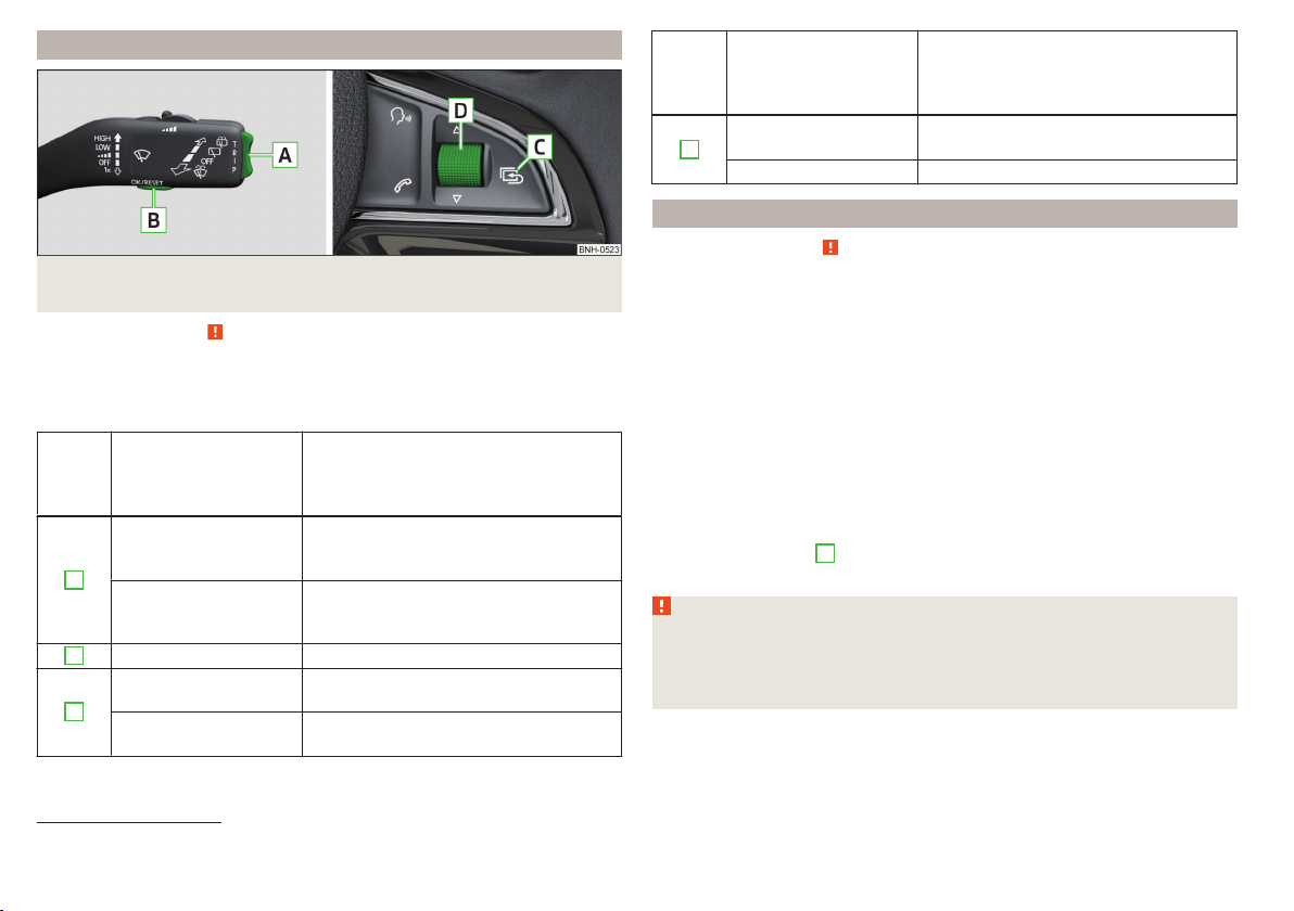
Using the information system
Fig. 26 Buttons/adjustment wheel: on the operating lever / on the multifunction steering wheel
Read and observe
Some functions of the information system can be operated using the buttons
on the multifunction steering wheel » Fig. 26.
Description of the operation
Button /
adjust-
ment
wheel
Briefly press at the top
or below for a longer
A
or below for a longer
B
C
Press and hold button
on page 41 first.
Action Operation
Select data / set data values
time
Press top
time
Display main menu of the
MAXI DOT display » page 46
Press briefly View information / confirm specification
Press briefly
To go up one level in the menu of the
MAXI DOT display » page 46
Display main menu of the
MAXI DOT display » page 46
Button /
adjust-
ment
Action Operation
wheel
Turn upwards or down-
D
wards
Select data / set data values
Press briefly View information / confirm specification
Display a low temperature
Read and observe on page 41 first.
Prompt in the MAXI DOT display
If the outside temperature while driving drops to below +4°C, the following
icon appears on the display in front of the temperature display . An audible
signal is emitted.
If the outside temperature is already below +4°C when turning the ignition on,
the icon appears immediately.
Prompt in the segment display
If the outside temperature while driving drops to below +4°C, the temperature
display » page 45, Outside temperature will show up with the following icon
in front . An audible signal is emitted.
If the outside temperature is already below +4°C when turning the ignition on,
the temperature display and the icon appear immediately.
After pressing button A » Fig. 26 on page 42, the most recently displayed data is shown.
WARNING
Even at outside temperatures of around +4 °C, black ice may still be present
on the road surface! You should therefore not rely solely on the outside
temperature display for an indication of whether there is black ice on the
road.
1)
1)
Applies to vehicles with the multifunction display (MFA).
42
Using the system
Page 46

Gear recommendation
Fig. 27
Information on the selected
gear / Gear recommendation
WARNING
The driver is always responsible for selecting the correct gear in different
driving situations, such as overtaking.
For the sake of the environment
A suitably selected gear has the following advantages.
■
It helps to reduce fuel consumption.
■
It reduces the operating noise.
■
It protects the environment.
■
It benefits the durability and reliability of the engine.
Read and observe on page 41 first.
The function of the gear recommendation is to help reduce fuel consumption.
A suitable gear is engaged, if necessary, a recommendation to shift to high or
lower gear is displayed.
Display » Fig. 27
Optimal gear engaged
Recommended gear
Recommended gear
The gear recommendation is intended only for vehicles with a manual transmission or for vehicles with an automatic transmission in manual shift mode
(Tiptronic).
The recommended 1) gear and the arrow icon 2) is displayed.
- Recommends that you shift to a higher gear.
›
- Recommends that you shift to a lower gear
›
If for example is shown in the display with vehicles that have manual gearboxes this indicates that it is better to shift from a lower gear to the 4th gear.
If for example is shown in the display with vehicles that have automatic
gearboxes and are in the manual switching mode (Tiptronic), this indicates
that it is better to shift from the 4th gear to a higher gear.
1)
With vehicles that have an automatic gearbox and in the manual switching mode (Tiptronic) the current-
ly engaged gear is shown.
2)
For vehicles with segment display the arrow is displayed behind the gear indication.
Door, boot or engine compartment warning
Read and observe
Vehicles with a MAXI DOT display
If at least one door, the boot or bonnet is open, the display indicates the relevant open door, boot or bonnet vehicle icon.
Vehicles with a segment display
If at least one door or the tailgate is open, the warning light in the instrument cluster illuminates » page 36.
An acoustic signal will also sound if you drive the vehicle above 6 km/h when a
door is open.
on page 41 first.
Multifunction display (MFD)
Introduction
This chapter contains information on the following subjects:
Memory 44
Information overview
Warning at excessive speeds
The driving data is displayed on the multifunction display.
Information system
45
46
43
Page 47
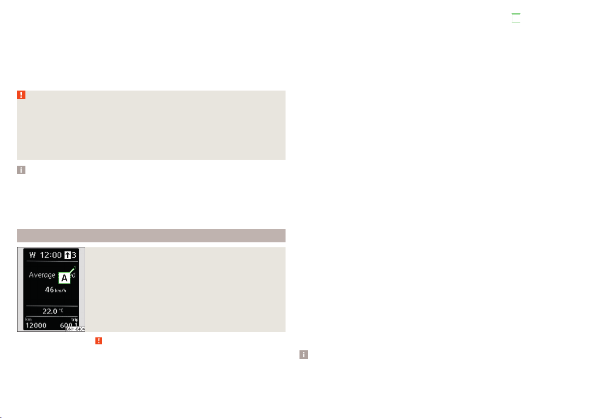
The multifunction display only operates when the ignition is switched on. After
the ignition is switched on, the function that was last selected before switching off the ignition is displayed.
For vehicles with a MAXI DOT display, the menu item MFD must be selected
and confirmed in the main menu » page 46, MAXI DOT display.
On vehicles with a MAXI DOT display, there is an option to fade out some of
the information » page 47, Settings.
WARNING
■
Concentrate fully at all times on your driving! As the driver, you are fully
responsible for the operation of your vehicle.
■
Even at outside temperatures of around +4 °C, black ice may still be
present on the road surface! You should therefore not rely solely on the
outside temperature display for an indication of whether there is black ice
on the road.
Note
■
In certain national versions the displays appear in the Imperial system of
measures.
■
If the display of the second speed is activated in mph, the current speed is
not indicated in km/h on the display.
■
The amount of fuel consumed will not be indicated.
Memory
Fig. 28
Multi-function display - memory display
Read and observe on page 44 first.
In memory the values of elements of the multifunction display(e.g. average
fuel consumption) are recorded.
The multifunction display is equipped with two memories, 1 and 2.
Display of the selected memory in the display at the position A. » Fig. 28
Single-trip memory
Total trip memory
Select memory
Select the corresponding element of the multifunction display » page 45,
›
Information overview.
Confirm details again to select the desired memory.
›
Resetting
Select the corresponding element of the multifunction display » page 45,
›
Information overview.
Select the desired memory.
›
Press and hold to confirm the selected memory.
›
Single-trip memory (memory 1)
The single-trip memory collates the driving information from the moment the
ignition is switched on until it is switched off.
New data will also flow into the calculation of the current driving information if
the trip is continued within 2 hours after switching off the ignition.
If the trip is interrupted for more than 2 hours, the memory is automatically
erased.
Total-trip memory (memory 2)
The total-trip memory gathers data from any number of individual journeys up
to a total of 19 hours and 59 minutes or 1 999 kilometres driven (), and a total
of 99 hours and 59 minutes or 9 999 kilometres driven ().
The memory is deleted when either of these limits is reached and the calculation starts all over again.
Unlike the single-trip memory, the total-trip memory is not deleted after a period of interruption of driving of 2 hours.
The following values of the selected memory are set to zero.
Average fuel consumption.
›
Distance driven.
›
Average speed.
›
Driving time
›
Note
Disconnecting the vehicle battery will delete all memory data.
44
Using the system
Page 48

Information overview
Read and observe on page 44 first.
The information overview of the Multifunction Display (the number of items
displayed is different depending on equipment).
Outside temperature
The current outside temperature is displayed.
For vehicles with a MAXI DOT display this information is always shown.
Driving time
The time travelled since the memory was last erased is displayed.
If you want to measure the time travelled from a particular moment in time,
reset the memory to zero at that point in time » page 44, Memory.
The maximum time indicated in both memories is 19 hours and 59 minutes ()
and 99 hours and 59 minutes (). The indicator is set back to zero if this period
is exceeded.
Current fuel consumption
The current fuel consumption level is displayed in litres/100 km1). You can use
this information to adapt your driving style to the desired fuel consumption.
The display appears in litres/hour if the vehicle is stationary or driving at a low
speed2).
Average fuel consumption
The average fuel consumption since the memory was last erased is displayed
in litres/100 km1).
If you wish to determine the average fuel consumption over a certain period of
time, you must set the memory at the start of the new measurement to
zero » page 44, Memory. After erasing the memory, no value is displayed until
you have driven approx. 300 m.
The display is updated regularly while you are driving.
Range
The range indicates the distance you can still drive with your vehicle based on
the level of fuel in the tank and with the same style of driving as before.
The display is shown in steps of 10 km. After lighting up of the indicator light
the display is shown in steps of 5 km.
The fuel consumption over the last 50 km is used to calculate the information.
The range will increase if you drive in a more economical manner.
If the memory is set to zero (after disconnecting the battery), a fuel consumption of 10 l./100 km is calculated for the range; afterwards the value is updated
according to the style of driving.
Distance travelled
The distance travelled since the memory was last erased is displayed.
If you want to measure the distance travelled from a particular moment in
time, reset the memory to zero at that moment in time » page 44, Memory.
The maximum distance indicated in both memories is 1 999 km. () and
9 999 km (). The indicator is set back to zero if this period is exceeded.
Average speed
The average speed since the memory was last erased is displayed in km/hour .
To determine the average speed over a certain period of time, set the memory
to zero at the start of the measurement » page 44, Memory.
After erasing the memory, no data will appear for the first 300 m driven.
The display is updated regularly while you are driving.
Current driving speed
The current speed displayed is identical to the display on the speedometer
3
» Fig. 20 on page 30.
Oil temperature
If the engine oil temperature is in the range of 80-110 °C, the engine operating
temperature has been reached.
If the oil temperature is lower than 80 °C or above 110 °C, avoid high engine
revs, full throttle and high engine loads.
If the oil temperature is lower than 50 °C or if a fault in the system for checking the oil temperature is present, . symbols are displayed instead of the oil
temperature.
1)
On some models in certain countries, the display appears in kilometres/litre.
2)
On some models in certain countries, – -.- km/ltr. is displayed when the vehicle is stationary.
Information system
45
Page 49

Warning at excessive speeds
Set the speed limit, e.g. for the maximum permissible speed in
towns » page 46, Warning at excessive speeds.
Warning at excessive speeds
Read and observe on page 44 first.
Adjust the speed limit while the vehicle is stationary
Select the menu item Speed warning ( ) or ( ).
›
Activate the speed limit option by confirming this menu item1).
›
Set the desired speed limit, e.g. 50 km/h.
›
Store the speed limit by confirming the set value, or wait several seconds;
›
your settings will be saved automatically.
The speed limit can be adjusted from 30 km/h to 250 km/h in 5 km/h increments.
Adjusting the speed limit while the vehicle is moving
Select the menu item Speed warning ( ) or ( ).
›
Drive at the desired speed, e.g. 50 km/h.
›
Confirm the current speed as the speed limit.
›
If you wish to adjust the set speed limit, you can do so in 5 km/h intervals (e.g.
the accepted speed of 47 km/h increases to 50 km/h or decreases to 45 km/h).
Store the speed limit, or wait several seconds; your settings will be saved au-
›
tomatically.
Change or disable speed limit
Select the menu item Speed warning ( ) or ( ).
›
By confirming the stored value, the speed limit is disabled.
›
By reconfirming, the option to change the speed limit is activated.
›
If the set speed limit is exceeded, an audible signal will sound as a warning.
The menu item Speed warning (MAXI DOT display) or (Segment display) appears in the display at the same time as the set threshold.
The set speed limit value remains stored even after switching off the ignition.
MAXI DOT display
Introduction
This chapter contains information on the following subjects:
Main menu
Settings 47
Compass point display 47
The MAXI DOT display provides you with information about the current operat-
ing state of your vehicle. Depending on the vehicle equipment, it also provides
you with data relating to the radio, multifunction display (MFD), mobile phone,
navigation system, automatic gearbox » page 108 and devices connected via
the MDI input.
WARNING
Concentrate fully at all times on your driving! As the driver, you are fully responsible for the operation of your vehicle.
Main menu
Read and observe on page 46 first.
Press and hold button A or C » Fig. 26 on page 42 to activate the MAIN
MENU. By briefly pressing the C button you will reach one level higher.
Main menu items (depending on vehicle equipment)
■
MFD (Multifunction display) » page 43
■
Audio » Operating instructions for the radio
■
Navigation » Operating instructions for the navigation system
■
Phone » page 94;
■
Vehicle status » page 33
■
Settings » page 47
The Audio and Navigation menu items are only displayed when the factory-fitted radio or navigation system is switched on.
46
1)
If no value is set the output value 30 km/h is automatically displayed.
46
Using the system
Page 50

Note
■
If warning messages are displayed, these messages must be verified to ac-
cess the main menu » page 42, Using the information system.
■
If the display is not activated at that moment, the menu always shifts to one
of the higher levels after approx. 10 seconds.
■
Using the factory-fitted radio or navigation system » Radio operating in-
structions or» navigation system operating instructions.
Settings
Read and observe on page 46 first.
You can change certain settings by means of the MAXI DOT display. The current menu item is shown in the top of the display under a line.
The following information can be selected (depending on the equipment installed in the vehicle).
Language
You can set the language for the display texts here.
MFD data
Activate or deactivate certain displays of the multifunction display here.
Time
The time, time format (12 or 24 hour indicator) and the changeover between
summer/winter time can be set here.
Winter tyres
Here, the speed and the switching on and off of the acoustic signals when exceeding this speed can be adjusted. This function is, for example, used for winter tyres where the maximum permissible speed is lower than the maximum
speed of the vehicle » page 152, Tyres and wheel rims.
As soon as the parking procedure is completed, an audible signal sounds and
the following message appears in the information display.
Winter tyres: maximum ... km/h.
Units
The units for the temperature, consumption and distance driven can be set
here.
Alt. speed dis.
Here, the display of the second speed in mph1) can be activated.
Further information » page 33, Display of the second speed.
Service
The days and kilometres remaining until the next service can be displayed
here.
Factory setting
The display functions can be restored to their factory settings here.
Compass point display
Read and observe on page 46 first.
For vehicles with a factory fitted navigation system, an abbreviation for each
point of the compass (depending on the current direction of travel) is shown
on the top left-hand corner of the display.
The compass point display only operates when the ignition is switched on.
Service interval display
Introduction
This chapter contains information on the following subjects:
Prompt in the MAXI DOT display
Prompt in the segment display
Resetting the service interval display
The service interval display shows the time and mileage to the next service
event.
The service due date is automatically displayed on the display and this information can be displayed manually if necessary.
The kilometre indicator or the days indicator reduces in steps of 100 km or,
where applicable, days until the service due date is reached.
The information regarding the service intervals can be found in the service
schedule.
48
48
49
1)
For models with the speedometer in mph, the second speed is displayed in km/h.
Information system
47
Page 51

Note
Information is retained in the Service Interval Display even after the vehicle
battery is disconnected.
Prompt in the MAXI DOT display
Oil change service
If an oil change service is due, the following message appears: Oil change in ...
km or ... days.
As soon as the service interval date has been reached, the message Oil
change now! appears once the ignition has been switched on.
Inspection
If an inspection is due, the following message appears: Inspection in ... km
or ... days.
As soon as the service interval date has been reached, the message Inspection now! appears once the ignition has been switched on.
Displaying the distance and days until the next service interval
You can view the remaining distance and days until the next service appointment at any time when the ignition is switched on by going to the Service
menu item » page 47, Settings or from the Vehicle status in the main menu of
the Maxi DOTdisplay. » page 46, Main menu .
The following message is displayed for 10 seconds.
Oil change ... km / ... days
Inspection ... km / ... days
Prompt in the segment display
Fig. 29
Segment display: Example of a
message
Description of image » Fig. 29
Service due
A
Differentiating between types of service
B
Days remaining until the next service interval
C
Kilometres remaining until the next service interval
Differentiating between types of service
The service type is determined by the number in position A » Fig. 29.
Oil change service
Inspection
Service due
If a service becomes due, then the following information is displayed for about
10 seconds » Fig. 29.
The number 1 or 2 is displayed in position A.
›
The symbol and the number of days remaining until the next service inter-
›
val are displayed in position B.
The symbol and the number of kilometres remaining until the next service
›
interval are displayed in position C.
As soon as the due date for the service has been reached, the flashing icon
and the message OIL CHNG or INSPEC_ appear in the display for about 20 seconds after the ignition has been switched on.
Display the days and distance until the next service interval
You can press button 4 » Fig. 21 on page 30 repeatedly to display the remaining distance and time to until the next service whenever the ignition is switched on.
1)
1)
The kilometres remaining until the next service interval are displayed instead of the odometer.
48
Using the system
Page 52

Information on the oil change service is displayed at first, followed by information on the inspection when button 4 is pressed again.
The number 1 or 2 is displayed in position A.
›
The symbol and the number of days remaining until the next service inter-
›
val are displayed in position B.
The symbol and the number of kilometres remaining until the next service
›
interval are displayed in position C.
Resetting the service interval display
We recommend that the display reset is completed by a specialist garage.
We recommend that you do not reset the service interval display yourself. Incorrectly setting the service interval display could cause problems to the vehicle.
Variable service interval
For vehicles with variable service intervals, after resetting the oil change service display, the values of a new service interval are displayed, which are based
on the previous operating conditions of the vehicle.
These values are then continuously matched according to the actual operating
conditions of the vehicle.
Unlocking and opening
Unlocking and locking
Introduction
This chapter contains information on the following subjects:
With the key on the lock cylinder unlock / lock 50
Unlocking/locking with the remote control key 50
Opening/closing a door 51
Safe securing system 51
Individual settings 52
Locking and unlocking the vehicle with the central locking button 52
Child safety lock 53
Malfunctions 53
Your car is equipped with a central locking system.
The central locking system allows you to lock and unlock all doors, the fuel fill-
er flap and boot lid at the same time.
Depending on the equipment configuration, the following is true after
unlocking
The turn signal lights flash twice as confirmation that the vehicle has been
›
unlocked.
The doors, the boot lid and the fuel filler flap are unlocked.
›
The interior light, which is switched by the door contact, comes on.
›
The SafeLock system is switched off.
›
The indicator light in the driver door stops flashing.
›
The anti-theft alarm system is deactivated.
›
If you unlock the vehicle and do not open a door or the boot lid within the next
30 seconds, the vehicle will lock again automatically and the SafeLock system
or anti-theft alarm system will be switched on. This function is intended to
prevent the car being unlocked unintentionally.
Depending on the equipment configuration, the following is true after
locking
The turn signal lights flash once as confirmation that the vehicle has been
›
locked.
The doors, the boot lid and the fuel filler flap are locked.
›
The interior lights connected over the door contact go off.
›
Unlocking and opening
49
Page 53

The SafeLock system is switched on.
›
The warning light in the driver door begins flashing.
›
The anti-theft alarm system is activated.
›
If the doors or the boot lid remain open after the vehicle has been locked, the
turn signal lights do not flash until they have been closed.
WARNING
■
Never leave the key in the vehicle when you exit the vehicle. Unauthorized persons, such as children, for example, could lock the car, turn on the
ignition or start the engine - there is a danger of injury and accidents!
■
When leaving the vehicle, never leave persons who are not completely independent, such as children, unattended in the vehicle. The children might,
for example, release the handbrake or take the vehicle out of gear. The vehicle could then start to move – risk of injury and accidents! These individuals might also not be able to leave the vehicle on their own or to help
themselves. Can be fatal at very high or very low temperatures!
CAUTION
■
Each key contains electronic components; therefore it must be protected
against moisture and severe shocks.
■
Keep the groove of the keys absolutely clean. Impurities (textile fibres, dust,
etc.) have a negative effect on the functionality of the locking cylinder and ignition lock.
■
The battery must be replaced if the central locking or anti-theft alarm system
does react to the remote control at less than approx. 3 metres
away » page 170.
■
When leaving the vehicle, always check if it is locked.
■
If the driver's door has been opened, the vehicle cannot be locked.
Note
In the event of an accident in which the airbags are deployed, the locked doors
are automatically unlocked in order to enable rescuers to gain access to the
vehicle.
With the key on the lock cylinder unlock / lock
Fig. 30
Left side of the vehicle: Turning
the key for unlocking and locking
the vehicle
Read and observe and on page 50 first.
The key allows you to unlock or lock the vehicle via the lock cylinder in the
driver's door.
Unlocking / locking the vehicle with the key » Fig. 30
Unlocking the vehicle
Locking the vehicle
Unlocking/locking with the remote control key
Fig. 31
Remote control key
Read and observe and on page 50 first.
Function and description of the remote control key » Fig. 31
Unlocking the vehicle
Locking the vehicle
Unlocking / locking the boot lid
A
Button for the fold out / fold in of the key
B
Warning light
50
Using the system
Page 54
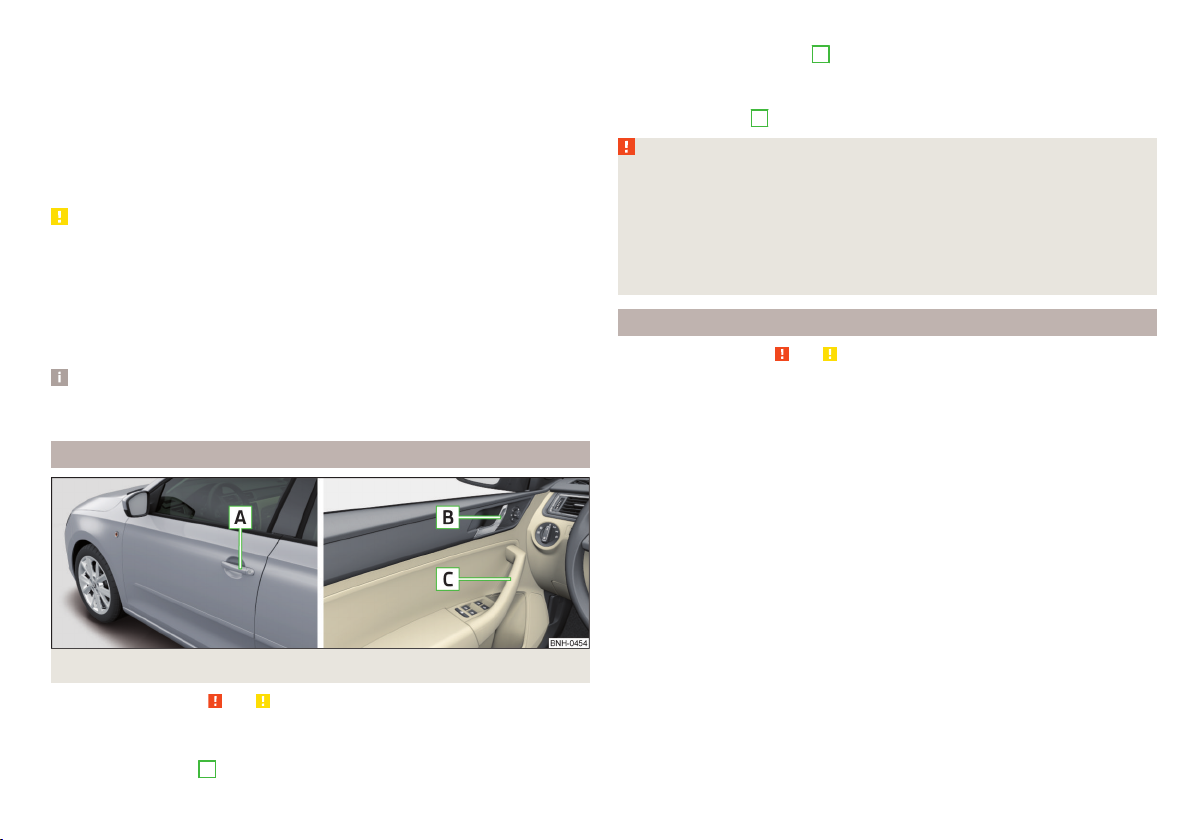
Unlocking / locking the boot lid
Briefly pressing the symbol key unlocks the boot lid. After unlocking, the
boot lid can be opened with the button in the handle above the number plate.
Pressing and holding the symbol key releases the boot lid (partially
opened).
If the boot lid is unlocked or released with the key symbol on the remote
control key, then the lid is automatically locked after closing.
You can set a lock delay » page 55.
CAUTION
■
Operation of the remote control may temporarily be affected by signal interference from transmitters close to the car and which operate in the same frequency range (e.g. mobile phone, TV transmitter).
■
Only operate the remote control when the doors and boot lid are closed and
the vehicle is in your line of sight.
■
The operating range of the remote control key is approx. 30 m. But this range
of the remote control can be reduced if the batteries are weak.
Note
A ŠKODA partner can also activate/deactivate the acoustic signals on vehicles
with an anti-theft alarm system.
Opening/closing a door
Fig. 32 Door handle/door opening lever
Read and observe
Opening from the outside
Unlock the vehicle.
›
Pull on door handle A » Fig. 32 on the door you wish to open.
›
and on page 50 first.
Opening from the inside
Pull on door opening lever B of the respective door and push the door away
›
from you.
Closing from the inside
Grasp pull handle C and close the door.
›
WARNING
■
Make sure that the door has closed correctly as it can open suddenly
while driving – risk of death!
■
Only open and close the door when there is no one in the opening/closing
range – risk of injury!
■
An opened door can close automatically if there is a strong wind or the
vehicle is on an incline – risk of injury!
■
Never drive with the doors open - there is a risk of death!
Safe securing system
Read and observe
The door locks are blocked automatically if the vehicle is locked from the outside. The vehicle cannot be opened from the inside any more.
This fact is pointed out by the following message on the display of the instrument cluster after switching off the ignition.
Check SAFELOCK! Log book!
CHECK DEADLOCK
Switching off
The safe lock can be switched off in one of the following ways.
By locking twice within 2 seconds.
›
By disabling the interior monitoring » page 54, Interior monitor and towing
›
protection.
If the vehicle is locked and the safe securing system is switched off, the door
can be opened separately from the inside by a single pull on opening lever.
Switching on
The safelock switches on automatically the next time the vehicle is locked and
unlocked.
Switch-off display
The indicator light in the driver door flashes for about 2 seconds fast, goes out
and starts to flash at longer intervals after about 30 seconds.
and on page 50 first.
Unlocking and opening
51
Page 55

Switch-on display
The warning light flashes for around 2 seconds in quick succession, afterwards
it begins to flash evenly at longer intervals.
WARNING
If the car is locked and the safe securing system activated, no people must
remain in the car as it will then not be possible to either unlock a door or
open a window from the inside. The locked doors make it more difficult for
rescuers to get into the vehicle in an emergency – risk to life!
Individual settings
Read and observe and on page 50 first.
Opening a single door
The function allows you to unlock only the driver's door and the fuel filler flap.
The other doors and the boot lid remain locked and are only unlocked after being opened again.
Automatic locking/unlocking
All doors are locked from a speed of around 15 km/h. The button in the handle
of the boot lid is deactivated.
If the ignition key is withdrawn, the car is then automatically unlocked again. It
is also possible to unlock the vehicle by pressing the central locking button .
Note
■
Individual settings can be carried out in a specialist workshop.
■
For some countries with right-hand steering the function of the single door
opening is set at the factory.
Locking and unlocking the vehicle with the central locking button
Read and observe and on page 50 first.
If the vehicle has not been locked from outside, the » Fig. 33 button can be
used to unlock or lock the vehicle.
Unlocking / locking » Fig. 33
If the icon in the button is lit, the vehicle is locked.
The central locking system also operates if the ignition is switched off.
The following applies after locking.
Opening the doors and the boot lid from the outside is not possible.
›
The doors can be unlocked and opened from the inside by a single pull on the
›
opening lever of the respective door.
In the event of an accident in which the airbags are deployed, the locked
›
doors are automatically unlocked in order to enable rescuers to gain access
to the vehicle.
WARNING
■
Doors locked from the inside make it difficult for rescuers to get into the
vehicle in an emergency – risk to life!
■
If the Safelock system is switched on » page 51, the door opening levers
and the central locking buttons do not operate.
CAUTION
If at least one door has been opened, the vehicle cannot be locked.
52
Using the system
Fig. 33
Central locking button
Page 56

Child safety lock
Fig. 34 Rear door: left / right
Read and observe
The child safety lock prevents the rear door from being opened from the inside. The door can only be opened from the outside.
Switching the cooling system on and off » Fig. 34
Switching on
Switching off
You can switch the child safety lock on and off using the vehicle key.
and on page 50 first.
Malfunctions
Read and observe and on page 50 first.
Failure of the central locking
Upon failure of the central locking system the key only unlocks and locks the
driver's door. The other doors and the boot lid can be opened and closed in an
emergency.
Emergency locking of the door » page 171.
›
Emergency unlocking of the boot lid » page 171.
›
Displaying an error
If the indicator light in the driver's door initially flashes quickly for around 2
seconds, and then lights up for 30 seconds without interruption before flashing again slowly, you will need to seek the assistance of a specialist garage.
Discharged battery in the remote control key
If the red warning light
a button on the remote control key, the battery is empty.
B
» Fig. 31 on page 50 does not flash when you press
Replace the battery » page 170.
Anti-theft alarm system
Introduction
This chapter contains information on the following subjects:
Activating/deactivating 54
Interior monitor and towing protection 54
The anti-theft alarm system increases the level of protection against people
trying to break into the vehicle.
The alarm system triggers audible and visual signals if an attempt is made to
break into the vehicle (hereafter referred to only as alarm).
Triggering the alarm
The alarm is triggered when the following unauthorized actions are carried out
on the locked vehicle.
Opening the bonnet.
›
Opening the boot lid.
›
Opening the doors.
›
Manipulation of the ignition lock.
›
Towing the vehicle » page 54.
›
Movement in the vehicle » page 54.
›
Sudden and significant voltage drop of the electrical system.
›
Uncoupling the trailer » page 125, Attaching and detaching trailers.
›
If the driver's door of a vehicle with a remote control is unlocked and opened
by the lock cylinder, then the alarm is triggered.
Switching off the alarm
The alarm is turned off by pressing the button on the radio remote control
key or switching on the ignition.
CAUTION
Before leaving the vehicle, check that the doors and windows are closed in order to ensure that the alarm system is fully operational.
Note
The working life of the alarm siren is 5 years.
Unlocking and opening
53
Page 57

Activating/deactivating
Read and observe on page 53 first.
Activating
The alarm system is activated automatically approximately 30 seconds after
the vehicle is locked.
If the vehicle is unlocked and a door or the boot lid not opened within the next
30 seconds, the vehicle will lock again automatically and the safe securing system or anti-theft alarm system will be switched back on. This function is intended to prevent the car being unlocked unintentionally.
Deactivating
The alarm system is deactivated automatically after the vehicle is unlocked. If
the vehicle is not opened within 30 seconds, the alarm system is automatically
activated again.
Interior monitor and towing protection
Open the driver door.
›
Press the symbol button » Fig. 35 on the B column of the driver's side.
›
The illumination of the symbol in the button changes from red to orange.
Lock the vehicle within 30 seconds.
›
Deactivate the interior monitor and the towing protection if there is a possibility of the alarm being triggered by movements (e.g. by children or animals)
within the vehicle interior or if the vehicle has to be transported (e.g. by train
or ship) or towed.
CAUTION
■
The opened glasses storage compartment reduces the effectiveness of the
interior monitor. To ensure the full functionality of the interior monitor, the
glasses storage compartment must always be closed before locking the vehicle.
■
The anti-theft alarm system is activated when the vehicle is locked, even if
the safe securing system is deactivated. The interior monitor is however not
activated.
Fig. 35
Button for interior monitor and
towing protection
Read and observe on page 53 first.
The interior monitor detects movements inside the car and then triggers the
alarm.
The tow-away protection triggers the alarm if a vehicle is registered as being
on an inclination.
Activating
The interior monitor and the towing protection are activated automatically after the vehicle is locked.
Deactivating
Switch off the ignition.
›
54
Using the system
Luggage compartment lid
Introduction
This chapter contains information on the following subjects:
Opening/closing 55
Delayed locking of the boot lid
WARNING
■
Ensure that the lock is properly engaged after closing the boot lid. Otherwise, the lid might open suddenly while the vehicle is moving, even if the
lid was locked – risk of accident!
■
Never drive with the boot lid open or unlatched, as otherwise exhaust
gases may get into the interior of the vehicle – risk of poisoning!
■
Do not press on the rear window when closing the luggage compartment
lid, as otherwise it could crack – risk of injury!
■
Make sure that when closing the boot lid, no body parts are crushed there is danger of injury!
55
Page 58

Note
The function of the button in the grip above the licence plate is deactivated
when starting off or at a speed of 5 km/hour or more for vehicles with central
locking. The function is restored after the vehicle stops and the door is
opened.
Opening/closing
Fig. 36 Opening / closing tailgate
Read and observe on page 54 first.
After unlocking the vehicle, the boot lid can be opened with the button in the
handle above the number plate.
Opening / closing tailgate » Fig. 36
1
Unlocking the door
2
Open flap
3
Closing the flap (by pulling the handle)
Delayed locking of the boot lid
Read and observe
If the boot lid is unlocked with the symbol button on the remote control
key, then the door is automatically locked after closing.
The period after which the boot lid is locked automatically can be extended by
a specialist garage.
After activation of delayed locking, the boot lid can be opened again after closing within a limited period.
Delayed locking can be deactivated by a specialist garage at any time.
on page 54 first.
CAUTION
There is a risk of unwanted entry into the vehicle before the boot lid is locked
automatically. We therefore recommend locking the vehicle with the symbol
button on the remote control key.
Power windows
Introduction
This chapter contains information on the following subjects:
Opening/closing the windows
Force limit 56
The electrical power windows can only be operated when the ignition is
switched on.
WARNING
The electrical power windows are fitted with a force limiter » page 56. If
there is an obstacle, the closing process is stopped and the window goes
down by several centimetres. However, the windows should be closed
carefully – risk of injury!
CAUTION
■
Keep the windows clean to ensure the correct functionality of the electric
windows.
■
In the event that the windows are frozen, first of all eliminate the
ice » page 134, Windows and external mirrors and only then operate the electrical power windows. Otherwise, the window sealing and the electrical power
window mechanism could be damaged.
■
Make sure that the windows are closed whenever you leave the locked vehicle.
For the sake of the environment
At high speeds, you should keep the windows closed to prevent unnecessarily
high fuel consumption.
56
Unlocking and opening
55
Page 59

Note
■
When driving always use the existing heating, air conditioning and ventilation system for ventilating the interior of the vehicle. If the windows are
opened, dust as well as other dirt can get into the vehicle and in addition the
wind noise is more at certain speeds.
■
The window lift mechanism is equipped with protection against overheating.
Repeated opening and closing of the window can cause this mechanism to
overheat. If this happens, it will not be possible to operate the window for a
short time. You will be able to operate the window again as soon as the overheating protection has cooled down.
Opening/closing the windows
Fig. 37 Power window buttons
Read and observe and on page 55 first.
All windows can be operated from the driver's seat.
Power window buttons » Fig. 37
A
Left front door
B
Right front door
C
Left rear door
D
Right rear door
E
Disable / enable the buttons in the rear doors
Opening
Lightly press the appropriate button down and hold it until the window has
›
moved into the desired position.
Releasing the button causes the window to halt immediately.
The driver's window can be completely opened automatically by briefly pressing the button as far as it will go. Renewed pressing of the button causes the
window to stop.
Closing
Pull gently on the top edge of the corresponding button and hold until the
›
window has moved into the desired position.
Releasing the button causes the window to halt immediately.
Disable / enable the buttons in the rear doors
Press the button E » Fig. 37.
›
When the buttons are disabled in the rear doors, the warning light in the
button E illuminates.
WARNING
If the rear seats are accommodating people who are not completely independent, e.g. children, it is recommended that for safety reasons the buttons in the rear doors are disabled with the button E.
Force limit
Read and observe
The electrical power windows are fitted with a force limiter.
If there is an obstacle, the closing process is stopped and the window goes
down by several centimetres.
If the obstacle prevents the window from being closed during the next 10 sec-
onds, the closing process is interrupted once again and the window goes down
by several centimetres.
If you attempt to close the window again within 10 seconds of the window being moved down for the second time, even though the obstacle was not yet
been removed, the closing process is only stopped. During this time it is not
possible to automatically close the window. The force limiter is still switched
on.
The force limiter is only switched off if you attempt to close the window again
within the next 10 seconds - the window will now close with full force!
If you wait longer than 10 seconds, the force limiter is switched on again.
and on page 55 first.
56
Using the system
Page 60

Mechanical windows
Introduction
This chapter contains information on the following subjects:
Open / close window
The window can be operated mechanically by means of the handle attached to
the respective door panel.
WARNING
The windows should nevertheless be closed carefully – risk of injury!
CAUTION
■
In the event that the windows are frozen, first of all eliminate the
ice » page 134, Windows and external mirrors and only then operate the electrical power windows. Otherwise, the window sealing and the electrical power
window mechanism could be damaged.
■
Make sure that the windows are closed whenever you leave the locked vehicle.
For the sake of the environment
At high speeds, you should keep the windows closed to prevent unnecessarily
high fuel consumption.
Note
When driving always use the existing heating, air conditioning and ventilation
system for ventilating the interior of the vehicle. If the windows are opened,
dust as well as other dirt can get into the vehicle and in addition the wind
noise is more at certain speeds.
Open / close window
57
Fig. 38 Window operation: left / right
Read and observe
Only one window can be operated mechanically at any time.
Opening
Lift the crank in the direction of arrow A » Fig. 38.
Closing
Turn the crank in the direction of the arrow B » Fig. 38.
and on page 57 first.
Unlocking and opening
57
Page 61

Lights and visibility
Lights
Introduction
This chapter contains information on the following subjects:
Operating the light function 58
Daytime running lights(DAY LIGHT) 59
Turn signal and main beam 60
Automatic driving lamp control 60
Fog lights 61
Fog lights with CORNER function 61
Rear fog light 61
COMING HOME / LEAVING HOME 62
Hazard warning light system 62
Parking light 63
Driving abroad 63
Unless otherwise stated, the lights only work when the ignition is switched on.
The arrangement of the controls right-hand drive models may differ from the
layout shown in » Fig. 39 on page 58. The symbols which mark the individual
positions of the controls are identical.
WARNING
■
The activation of the lights should only be undertaken in accordance with
national legal requirements.
■
The driver is always responsible for the correct settings and use of the
lights.
WARNING (Continued)
■
The automatic driving lamp control only operates as a support and
does not release the driver from his responsibility to check the lights and, if
necessary, to switch on the light depending on the prevailing light conditions. The light sensor cannot, for example, detect rain or snow. Under
these conditions we recommend switching on the low beam or fog lights!
■
Never drive with only the side lights on! The side lights are not bright
enough to light up the road sufficiently in front of you or to be seen by other oncoming traffic. Therefore always switch on the low beam when it is
dark or if visibility is poor.
Note
The headlights may mist up temporarily. When the driving lights are switched
on, the light outlet surfaces are free from mist after a short period, although
the headlight lenses may still be misted up in the peripheral areas. This mist
has no influence on the life of the lighting system.
Operating the light function
Fig. 39
Light switch and control dial for
headlight range adjustment
Read and observe on page 58 first.
Switching lights on and off
Depending on the equipment configuration, the light switch A» Fig. 39 can be
moved to the following positions.
Turn switch
Switching off lights (except daytime running lights)
Automatic switching lights on and off » page 60
58
Using the system
Page 62

Switching on the parking light or parking lights1) » page 63
Switch on low beam
Pull switch
Switch on the front fog lamp » page 61
Switching on the rear fog light » page 61
Headlight range control
Turning the dial B » Fig. 39 from the position in means the headlight adjustment is gradually adjusted and thereby shortens the light cone.
The positions of the width of illumination correspond approximately to the following car load.
Front seats occupied, boot empty
All seats occupied, boot empty
All seats occupied, boot loaded
Driver seat occupied, boot loaded
We recommend you adjust the headlight beam when the low beam is switched
on.
WARNING
Always adjust the headlight beam to meet the following conditions.
■
The vehicle does not dazzle other road users, especially oncoming vehi-
cles.
■
The beam range is sufficient for safe driving.
Note
■
An audible warning signal will sound if the light switch is in the or position, the ignition key is removed and the driver's door is opened. The audible
warning signal is switched off after a few seconds or as a result of door contact when the driver's door is closed. However, the side lights remain on to illuminate the parked vehicle if necessary.
■
If leaving the vehicle without needing the parking lights on, always turn
the light switch to position .
1)
Daytime running lights(DAY LIGHT)
Read and observe on page 58 first.
The daytime running lights (the only function) provides the lighting of the front
vehicle range.
The lights are switched on automatically if the following conditions are met.
The light switch is in the position or
The ignition is switched on.
The parking aid is activated.
Deactivating the function
Switch off the ignition.
›
Remove the fuse for the daytime running lights » page 173, Fuses in the
›
dash panel.
Activating the function
Switch off the ignition.
›
Use a fuse of appropriate amperage for the daytime running
›
lights » page 173, Fuses in the dash panel.
Disable function on vehicles with the START-STOP system or with the
automatic driving light control
Switch off the ignition.
›
Slide the turn signal light lever (» Fig. 40 on page 60) downwards and hold
›
it in this position.
Switch on the ignition – wait until the left-turn signal light flashes 4x.
›
Switch off the ignition – an audible signal sounds which confirms the deacti-
›
vation of the function.
Release the turn signal stalk.
›
Function on vehicles with the START-STOP system or with the automatic
driving light control
Switch off the ignition.
›
Slide the turn signal light lever (» Fig. 40 on page 60) upwards and hold it in
›
this position.
Switch on the ignition – wait until the right-turn signal light flashes 4x.
›
Switch off the ignition – an audible signal sounds which confirms the activa-
›
tion of the function.
» Fig. 39 on page 58.
1)
On vehicles with the instrument cluster - Version 1 » page 30 the symbol also illuminates on the light
switch.
Lights and visibility
59
Page 63

Release the turn signal stalk.
›
WARNING
When the daytime running light is switched on, the side lights (neither at
the front nor the rear) and the number plate lights are not lit. Therefore always switch on the low beam when the visibility is poor.
Turn signal and main beam
Fig. 40
Operating lever: Turn signal and
main beam operation
When the right flashing light is switched on, the warning light flashes in the
instrument cluster.
The turn signal light switches itself off automatically when driving around a
curve or after making a turn.
The warning light flashes at twice its normal rate if a bulb for the turn signal
light fails.
“Convenience turn signal”
If you only wish to flash three times, briefly push the lever to the upper or lower pressure point and release again.
WARNING
Only turn on the main beam or the headlight flasher if other road users will
not be dazzled.
Automatic driving lamp control
Read and observe on page 58 first.
Lever positions » Fig. 40
A
Switch on right turn signal
B
Switch on left turn signal
C
Switch on high beam (spring-loaded position)
D
Switching off main beam / switching on headlamp flasher (spring-loaded
position)
Main beam
The main beam can only be switched on when the low beam lights are on.
The warning light illuminates in the instrument cluster when the headlight
is switched on.
Flasher
The headlight flasher can be operated even if the ignition is switched off.
The warning light illuminates in the instrument cluster when the headlight
flasher is switched on.
Flashing
When the left flashing light is switched on, the warning light flashes in the
instrument cluster.
60
Using the system
Fig. 41
Light switch: AUTO position
Read and observe on page 58 first.
If the light switch is in position
number plate lights are switched on or off automatically.
The light on/off switching is controlled by a sensor mounted under the windscreen in the holder of the inside mirror.
If the light switch is in position
light switch. If the light is switched on automatically, the symbol next to the
light switch also illuminates.
» Fig. 41, the parking lights, low beam and
, the lettering
illuminates next to the
Page 64

Automatic driving light control during rain
The low beam is switched on automatically if the following conditions are met.
The light switch is in position
Automatic wiping with rain - position 1 or wiping - position 2 or 3 is
turned on » page 66, Activating the windscreen wipers and washers.
The windscreen wipers are on for more than 15 s.
The light turns off about 4 minutes after turning off the wipers.
CAUTION
Do not attach any stickers or similar objects in front of the light sensor on the
windscreen to avoid impairing the function or its reliability.
» Fig. 41.
Fog lights
Fig. 42
Light switch - Switch front and
rear fog light
Read and observe on page 58 first.
Switching on/off
Turn the light switch to position or » Fig. 42.
›
Pull the light switch to position 1.
›
The front fog light is switched off in the reverse order.
The warning light » page 34 illuminates in the instrument cluster when the
fog lights are switched on.
Fog lights with CORNER function
Read and observe on page 58 first.
The CORNER function lights the front fog lamp on each side of the vehicle to
illuminate the area around the vehicle when turning, parking, etc.
The CORNER function is switched on automatically if the following conditions
are met.
The turn signal is switched on or the front wheels are turned sharply to
the right or left1).
The engine is running.
The vehicle is stopped or moves at a speed of no more than 40 km/h.
The low beam is switched on or the light switch is in the position
the low beam is switched on.
The daytime running lights are not switched on.
The fog lights are not switched on.
Note
The two fog lights are switched on when you shift into the reverse gear.
and
Rear fog light
Read and observe
Switching on/off
Turn the light switch to position or » Fig. 42 on page 61.
›
Pull the light switch to position 2.
›
The rear fog light is switched off in the reverse order.
The warning light » page 34 illuminates in the instrument cluster when the
rear fog light is switched on.
If the vehicle is not fitted with fog lights, the rear fog light is switched on by
pulling out the light switch directly to the only possible setting.
Only the rear fog light on the trailer illuminates if the vehicle has a factory-fitted towing device or a towing device from ŠKODA original accessories and it is
driven with a trailer.
on page 58 first.
1)
If both switch-on conditions are conflicting, for example, if the front wheels are turned to the left and
the right turn signal light is switched on, the turn signal light has the higher priority.
Lights and visibility
61
Page 65
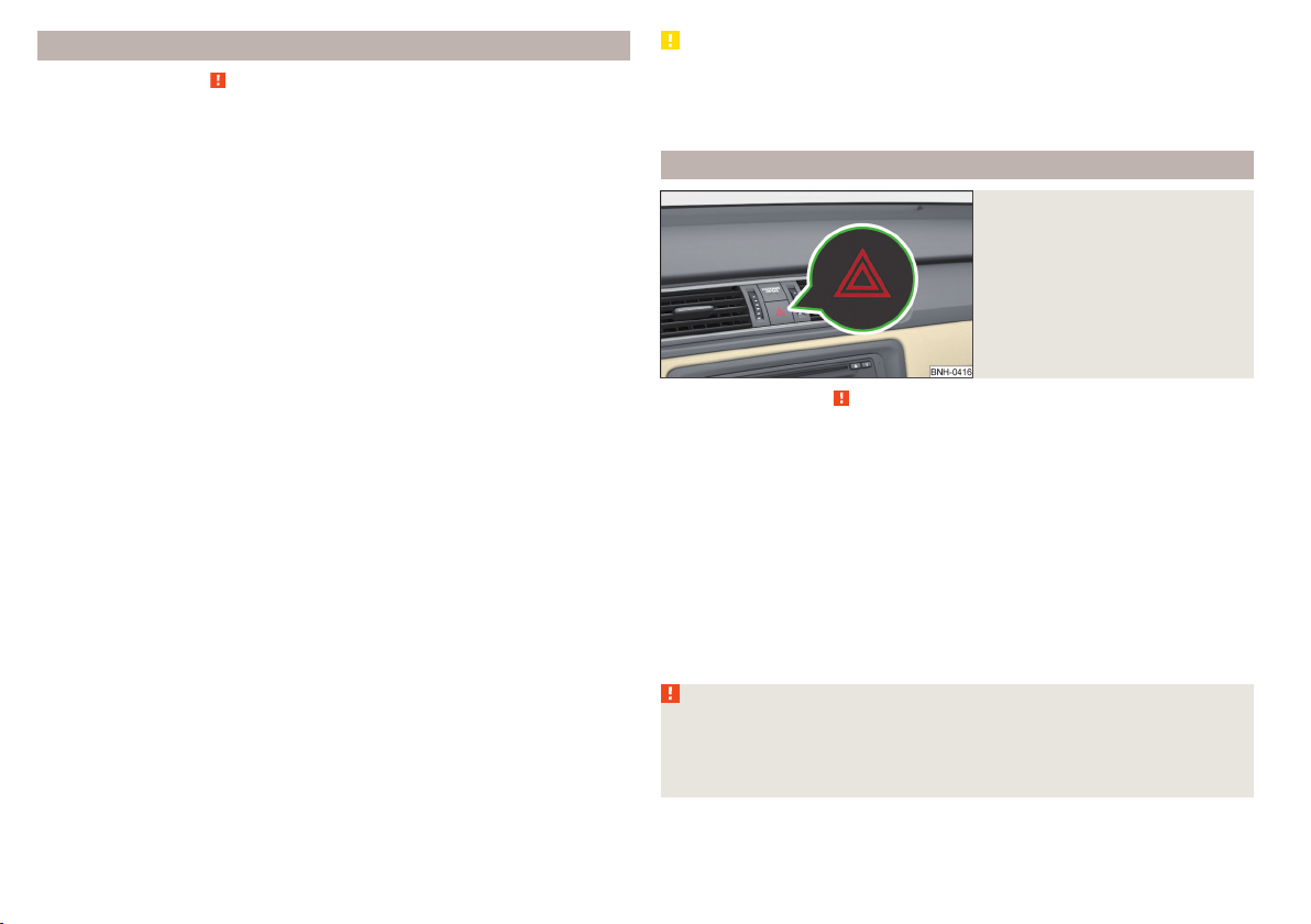
COMING HOME / LEAVING HOME
Read and observe on page 58 first.
COMING HOME (hereinafter referred to only as a function) switches the light
automatically for a short time after leaving the vehicle.
LEAVING HOME (hereinafter referred to only as a function) switches the light
automatically for a short time when approaching the vehicle.
The function switches on the following light, depending on the equipment
fitted.
Parking lights
›
Low beam
›
Entry lighting in the exterior mirrors
›
Licence plate light
›
Poorer visibility is evaluated by sensor mounted in the holder of the interior
mirror.
COMING HOME
The lights are switched on automatically if the following conditions are met.
The light switch is in position
The visibility in the vehicle environment is reduced.
The ignition is switched off.
The function was activated before leaving the vehicle by briefly switching
on the headlight flasher » page 60, Turn signal and main beam .
The driver's door was open - within 60 seconds after turning off the igni-
tion.
The light goes out 10 seconds after closing all of the doors and the boot lid.
If a door or the boot lid remains open, the light goes out after 60 seconds.
LEAVING HOME
The lights are switched on automatically if the following conditions are met.
The light switch is in position
The visibility in the vehicle environment is reduced.
The ignition is switched off.
The vehicle was unlocked with the radio remote control.
The light goes off after 10 seconds or when locking the vehicle.
» Fig. 41 on page 60.
» Fig. 41 on page 60.
CAUTION
■
Do not attach any stickers or similar objects in front of the light sensor on
the windscreen to avoid impairing the function or its reliability.
■
If this function is activated constantly, the battery will be heavily discharged
particularly in short-haul travel.
Hazard warning light system
Fig. 43
Button for hazard warning light
system
Read and observe on page 58 first.
Switching on/off
Press the button » Fig. 43.
›
All the turn signal lights on the vehicle flash at the same time when the hazard
warning light system is switched on. The warning light for the turn signals and
the warning light in the button also flash at the same time. The hazard warning light system can also be operated if the ignition is switched off.
If one of the airbags is deployed, the hazard warning light system will switch
on automatically.
If the turn signal light is switched on when the hazard warning light and the
ignition are both switched on, then only the turn signal light on the corresponding vehicle side will flash.
WARNING
Switch on the hazard warning light system if, for example, the following occurs.
■
You encounter a traffic congestion.
■
The vehicle must may have to be parked on the roadside due to a fault.
62
Using the system
Page 66

Parking light
Read and observe on page 58 first.
The parking light is provided for a temporary lighting of the parked vehicle.
Parking light switching on
Switch off the ignition.
›
Place the control lever into position A or B as far as it can go » Fig. 40 on
›
page 60 - the parking light on the right/left-hand side of the vehicle is
switched on.
If the right or left turn signal light has been switched on and the ignition is
switched off, the parking light is not automatically switched on.
Switching on the side light on both sides
Turn the light switch
›
hicle.
After pulling out the ignition key and opening the driver's door, an audible
warning sounds. After a few seconds or after closing the driver's door, the audible alarm is turned off, but the parking lights will remain switched on.
On vehicles with an instrument cluster -version 1 » page 30 the light switch
symbol also illuminates when the two-sided parking light is switched on.
CAUTION
Turning on the parking light means the battery is heavily loaded, especially
over short distances.
A
to position » Fig. 39 on page 58 and lock the ve-
Driving abroad
Read and observe
The low beam is set asymmetrically. It illuminates the side of the road on
which the vehicle is being driven to a greater extent.
When driving in countries with opposing traffic system (traffic on the left/
right), asymmetric headlight adjustment can dazzle oncoming traffic. In order
to avoid this, the headlights must be adjusted at a specialist garage.
Note
You can find out more information on adjusting the headlights at a specialist
garage.
on page 58 first.
Interior lighting
Introduction
This chapter contains information on the following subjects:
Front interior light
Rear interior light 64
Note
With the ignition off, the light turns off automatically after about 10 minutes.
Front interior light
Fig. 44 Operation of the front light: Version 1/version 2
Positions of the sliding light switch A » Fig. 44
Switching on
Switching off
Operating with the door contact switch
Switch for reading light B » Fig. 44
Switching left reading lamp on/off
Switching right reading lamp on/off
Conditions for operation of light with the door contact switch - setting
The system is turned on when any of the following is present.
The vehicle is unlocked.
›
One of the doors is opened.
›
The ignition key is removed.
›
63
Lights and visibility
63
Page 67

The system is turned off when any of the following is present.
The vehicle is locked.
›
The ignition is switched on.
›
About 30 seconds after all the doors have been closed.
›
Rear interior light
Fig. 45
Interior lights at the rear: Version 1/version 2
Rear light - version 1: press switch A» Fig. 45
Switching on/off
Rear light - version 2: move lens B» Fig. 45
Switching on
Switching off
Operating with the door contact switch
Rear light - version 1
The rear light is operated together with the front light 2).
When the front lighting is switched on, the rear lighting also turns on auto-
›
matically.
When the front lighting is switched off, the rear lighting can be turned on/off
›
as required.
1)
Visibility
Introduction
This chapter contains information on the following subjects:
Rear window heater
Front sun visors 65
Sun screen of the panoramic roof 65
Rear window heater
Fig. 46
Dash panel: Button for rear window heater
The heating for quick defrosting and ventilation of the rear window.
Button in the centre console » Fig. 46
Switching the rear window heater on/off
When the heater is switched on, a lamp illuminates inside the button.
The heating only works when the engine is running.
The heater automatically switches off after approximately 7 minutes.
For the sake of the environment
The heating should be switched off as soon as the window is de-iced or free
from mist. The reduced current consumption will have a favourable effect on
fuel economy.
64
1)
In this position, apply the same rules to the rear interior light as for the front interior light » page 63.
2)
This function only applies to certain countries. In some countries, the light at the rear is controlled independently from the light at the front.
64
Using the system
Page 68

Note
■
If the on-board voltage drops, the heater switches off automatically, in order
to provide sufficient electrical energy for the engine control » page 151, Auto-
matic load deactivation.
■
If the light is flashing inside the button the heater is off due to low battery.
Front sun visors
Fig. 47 Fold down the cover / swivel cover to the door and slide the mir-
ror cover
The sun visors protect you from the blazing sun.
Operation and description of the sun visor » Fig. 47
1
Fold down the cover
2
Swivel cover towards the door
A
Make-up mirror with cover
B
Slide mirror cover
WARNING
The sun visors must not be swivelled towards the side windows in the de-
ployment area of the head airbags if any objects are attached to them. Ini-
tiation of the head airbags may cause injury.
Sun screen of the panoramic roof
Fig. 48
Open sun screen
The sunshade protects against the blazing sun.
The sunshade of the panoramic roof can be opened manually in the direction
of arrow or closed in the opposite direction of the arrow » Fig. 48.
WARNING
When operating the sun blind, proceed with caution to avoid causing crushing injuries – risk of injury!
Windscreen wipers and washers
Introduction
This chapter contains information on the following subjects:
Activating the windscreen wipers and washers 66
Headlight cleaning system 67
The wiper and washer system provide a good view through the windscreen or
rear window.
The windshield wipers and the windshield washer system only operate if the
ignition is switched on.
Top up with windscreen wiper fluid » page 143.
Lights and visibility
65
Page 69

WARNING
■
Properly maintained windscreen wiper blades are essential for clear visi-
bility and safe driving » page 172.
■
Replace the windscreen wiper blades once or twice a year for safety rea-
sons. These can be purchased from a ŠKODA Partner.
■
Do not use the windscreen washer system at low temperatures, without
heating the windscreen beforehand. The window washer fluid could otherwise freeze on the windscreen and restrict the view to the front.
■
Automatic wiping during rain is only a support. The driver is not released
from the responsibility to set the function of the windscreen wipers manually depending on the visibility conditions.
CAUTION
■
If the ignition is switched off while the windscreen wipers are switched on,
the windscreen wipers will continue wiping in the same mode after the ignition is turned back on. The windscreen wipers could freeze up in cold temperatures between the time the ignition was turned off and when it was turned
back on again.
■
In cold temperatures and during the winter, check before the journey or be-
fore switching on the ignition that the wiper blades are not frozen to the
windscreen. If the windscreen wipers are switched on when the blades are frozen to the windscreen, this may damage both the blades and windscreen wiper motor!
■
Carefully peel frozen wiper blades off the windscreen.
■
Remove snow and ice from the windscreen wipers before driving.
■
Do not switch on the ignition if the front wiper arms are retracted. The wiper
arms could damage the paint of the bonnet.
■
If the windscreen wipers are handled carelessly, there is a risk of damage to
the windscreen.
Note
■
To avoid streaking, the wiper blades must be kept clean » page 136.
■
The windscreen washer nozzles for the windscreen are heated when the en-
gine is running and the outside temperature is less than approx. +10 °C.
Activating the windscreen wipers and washers
Fig. 49 Operation of the wipers and washer: front and rear
Read and observe
Lever positions
0
Wipers off
1
Periodic windscreen wiping/automatic wiping in rain
2
Slow windscreen wiping
3
Rapid windscreen wiping
4
Flick windscreen wiping, service position of the wiper
arms » page 172, (spring-loaded position)
5
Automatic wipe/wash for windscreen (spring-tensioned position)
6
Wiping the rear window pane (the windscreen wiper wipes at regu-
lar intervals after a few seconds)
7
Automatic wipe/wash for the rear window (spring-tensioned posi-
tion)
A
Switches for setting: the desired pause between the individual wip-
er strokes / the speed of the wiping in rain (operating lever in the
position 1)
Interval windscreen wiping
The wiping intervals are also speed-dependent regulated.
Automatic windscreen wiping in rain
The wiping intervals are controlled depending on the rain intensity.
Automatic wipe/wash for windscreen
The wash system operates immediately, the windscreen wipers wipe somewhat later.
and on page 66 first.
66
Using the system
Page 70
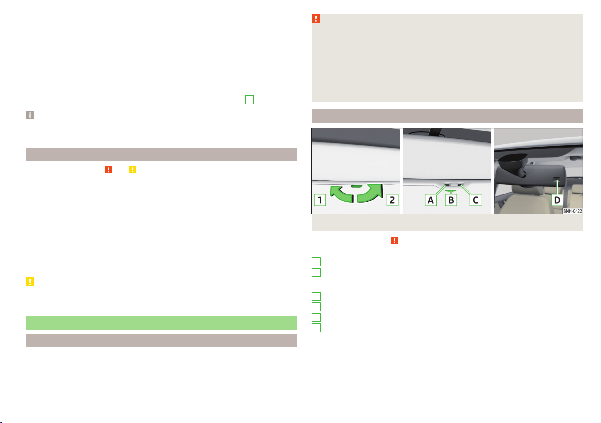
Letting go of the operating lever will cause the windscreen wash system to
stop and the wipers to continue for another 1 to 3 wiper strokes (depending on
the spraying duration).
Automatic wipe/wash for the rear window
The wash system operates immediately, the windscreen wiper wipes somewhat later.
Letting go of the operating lever will cause the windscreen wash system to
stop and the wiper to continue for another 1 to 3 wiper strokes (depending on
the spraying duration). The operating lever remains in position 6.
Note
The rear window is wiped once automatically if the windscreen wipers are on
when reverse gear is selected.
Headlight cleaning system
Read and observe and on page 66 first.
After the ignition is switched on, the headlights are always cleaned at the first
and after every tenth spray of the windscreen (setting 5 » Fig. 49 on
page 66), when the low beam or main beam is switched on.
You should remove stubborn dirt (such as insect residues) from the headlight
lenses at regular intervals, for example when refuelling. The following guidelines must be observed » page 134, Headlight glasses.
To ensure the proper operation of the cleaning system during the winter, any
snow should be removed from the washer nozzle fixtures and ice should be
cleared with a de-icing spray.
CAUTION
Never remove the nozzles from the headlight cleaning system by hand – risk of
damage!
Rear mirror
Introduction
This chapter contains information on the following subjects:
Interior mirror
Exterior mirror 68
WARNING
■
Make sure that the mirror is not covered by ice, snow, mist or other ob-
jects.
■
Convex (curved outward) or aspheric exterior mirrors increase the field of
vision. They do, however, make objects appear smaller in the mirror. These
mirrors are therefore only of limited use for estimating distances to the following vehicles.
■
Whenever possible use the interior mirror for estimating the distances to
the following vehicles.
Interior mirror
Fig. 50 Interior mirror: manual dimming / auto-dimming / light sensor
Read and observe
Mirrors with manual dimming » Fig. 50
1
Basic position of the mirror
2
Mirror blackout
Mirror with automatic dimming » Fig. 50
A
Warning light - lights when dimming is activated
B
Switch for the activation of the automatic mirror dimming
C
Light sensor
D
Light sensor on the back of the mirror
Mirror with automatic dimming
If the automatic dimming is enabled, the mirror dims automatically depending
on the light falling on the sensors.
67
When the interior lights are switched on or the reverse gear is engaged, the
mirror always moves back into the basic position (not dimmed).
on page 67 first.
Lights and visibility
67
Page 71

Do not attach external navigation devices on to the windscreen or in the vicinity of the automatic dimming interior mirror » .
WARNING
The illuminated display of an external navigation unit can lead to operational faults to the automatic dimming interior mirror – risk of accident.
WARNING
The mirrors with automatic dimming contain an electrolyte liquid which can
escape if mirror glass is broken.
■
The leaking electrolytic fluid can irritate the skin, eyes and breath apparatus. Immediately seek out fresh air and leave the vehicle. If this is not possible, at least open the window.
■
If you swallow electrolytic fluid, seek medical assistance immediately.
■
If your eyes or skin come into contact with the electrolytic fluid, immediately wash the affected area for a few minutes long with a lot of water.
Then consult a doctor immediately.
CAUTION
Automatic mirror dimming operates only properly if the light striking the sensors is not affected by other objects.
Exterior mirror
The movement of the mirror surface is identical to the movement of the rotary
knob.
Electrically-adjustable mirrors
The knob can be moved into the following positions » Fig. 51 - .
Adjust the left mirror
Adjust the right mirror
Switch off mirror control
Mirror heater
Folding in the exterior mirrors
The whole exterior mirror can be manually folded towards the side windows.
To put it back into its original position, it should be folded back from the side
window until it audibly clicks into place.
WARNING
Do not touch the exterior mirror surfaces, if the exterior mirror heating is
switched on - hazard of burning.
Note
■
The mirror heater only operates when the engine is running and up to an
outside temperature of +35 ℃.
■
If the electrical mirror setting fails at any time, the mirrors can be adjusted by
hand by pressing on the edge of the mirror surface.
Fig. 51 Exterior mirror operation: mechanical / electrical
Read and observe on page 67 first.
Adjust the position
The mirror can be adjusted to the desired position by moving the knob in the
direction of the arrow » Fig. 51.
68
Using the system
Page 72

Seats and head restraints
Adjusting the front seats
Seats and head restraints
Introduction
This chapter contains information on the following subjects:
Adjusting the front seats 69
Head restraints - adjusting height 70
Headrests - removing and installing 70
The driver's seat should be adjusted in such a way that the pedals can be fully
pressed to the floor with slightly bent legs.
The seat backrest on the driver's seat should be adjusted in such a way that
the upper point of the steering wheel can be easily reached with slightly bent
arms.
Correct adjustment of the seats is particularly important for the following reasons.
Reaching the controls safely and quickly.
›
A relaxed and fatigue-free body position.
›
Achieving the maximum protection offered by the seat belts and the airbag
›
system.
WARNING
■
Only adjust the driver's seat when the vehicle is stationary – risk of acci-
dent!
■
Caution when adjusting the seat! You may suffer injuries or bruises as a
result of adjusting the seat without paying proper attention.
■
Never carry more people than the number of seats in the vehicle.
■
Do not carry any objects on the front passenger seat, except objects de-
signed for this purpose (e.g. child seats) – risk of accident!
Note
After a certain time, play can develop within the adjustment mechanism of the
backrest angle.
Fig. 52
Control elements at the seat
Read and observe on page 69 first.
Control elements at the seat » Fig. 52
A
Adjusting a seat in a forward/back direction
B
Adjusting height of seat
C
Adjusting the angle of the seat backrest
Adjusting a seat in a forward/back direction
Pull lever A » Fig. 52(in the centre) in the direction of arrow and push the
›
seat in the required direction.
The lock must click into place after you release the lever.
Adjusting height of seat
Again push or pull the lever B » Fig. 52 in the direction of one of the arrows.
›
Adjusting the angle of the seat backrest
The seat back release (do not lean on).
›
Pull the lever C » Fig. 52 in direction of arrow and with your back set the
›
desired inclination of the seat back.
After releasing the lever the seat backrest will remain in the set position.
Seats and head restraints
69
Page 73

Head restraints - adjusting height
Headrests - removing and installing
Fig. 53 Head rests: move up / move down
Read and observe
Adjustment of the head rest heights is the same in the front and rear.
Best protection is achieved if the top edge of the head rest is at the same level
as the upper part of your head.
Move upwards
Push the headrest in the direction of arrow 1 » Fig. 53.
›
Move downwards
Press the locking button A in the direction of the arrow 2 and
›
hold » Fig. 53.
Push the headrest in the direction of arrow 3 .
›
WARNING
With seats occupied, the respective head rests must be correctly set (may
not be in the bottom position) - there is a risk of fatal injury!
Note
For the sports seats, the head restraints are integrated into the front seat
backrests. This headrest cannot be adjusted in height.
70
Using the system
on page 69 first.
Fig. 54 Front head rests: removal / installation
Fig. 55 Rear headrests: removal / installation
Read and observe on page 69 first.
Front restraint
Pull the restraint out of the seat backrest as far as the stop.
›
Press the locking button A in the direction of arrow 1, and pull the support
›
in the direction of arrow
To re-insert the head restraint, push it far enough down in the direction of
›
arrow 3 into the seat backrest until the locking button clicks into place.
Rear restraint
Pull the restraint out of the seat backrest as far as the stop.
›
Press the locking button B in the direction of arrow 4, while at the same
›
time using a flat screwdriver with a max. width of 5 mm to press the securing
button in opening C in the direction of arrow 5.
Remove the restraint in the direction of arrow 6.
›
2.
Page 74

To re-insert the head restraint, push it far enough down in the direction of
›
arrow 7 into the seat backrest until the locking button clicks into place.
WARNING
With seats occupied, the respective head rests must be installed and adjusted correctly - there is a risk of fatal injury!
Note
For the sports seats, the head restraints are integrated into the front seat
backrests. These headrests cannot be removed.
Seat features
Introduction
This chapter contains information on the following subjects:
Front seat heating
Front armrest 72
Rear armrest 72
Seat backrests 72
Front seat heating
Fig. 56
Buttons for heating the front
seats
The seat backrests and seats can be heated electrically.
The seat heating can only be switched on when the engine is running.
Buttons for the seat heater » Fig. 56
Left seat heating
Right seat heating
Switching on
Press the corresponding symbol button or » Fig. 56.
›
Pressing once switches the seat heating on at its maximum level - Level 2.
With repeated pressing of the switch, the intensity of the heating is reduced
until it is switched off.
The level of the seat heating is indicated by the number of illuminated warning
lights in the switch.
WARNING
If, as an occupant, you have a subdued pain and/or temperature sensitivity,
e.g. through medication, paralysis or because of chronic illness (e.g. diabetes), we recommend you do not use seat heating on the driver or front passenger seat. This can lead to burns on the back, the posterior and the legs
which are difficult to heal. If the seat heating is used, we recommend to
make regular breaks in your journey when driving long distances, so that
the body can recuperate from the stress of the journey. Please consult your
71
doctor, who can evaluate your specific condition.
CAUTION
■
Do not kneel on the seats or otherwise apply concentrated pressure to them.
■
The seat heating in the following cases will not turn on - there is a risk of
damaging the seat covers and seat heating.
■
The seats are not occupied by people.
■
Items are fastened or stored items on the seats, such as a child seat, a bag
and the like.
■
Additional seat covers or protective covers are fixed to the seats.
■
Clean the seat covers » page 138.
Note
■
If the seat heaters are set to their highest intensity - level 2, they are auto-
matically switched down to level 1 after 15 minutes.
■
If the on-board voltage drops, the seat heater switches off automatically, in
order to provide sufficient electrical energy for the engine control » page 151,
Automatic load deactivation.
Seats and head restraints
71
Page 75

Front armrest
Seat backrests
Fig. 57
Adjusting armrest
Setting the height
Lift the armrest fully upwards in the direction of the arrow » Fig. 57 and then
›
move it back down completely.
Move the armrest into one of the 5 locking positions.
›
The armrest includes a storage compartment » page 78.
Rear armrest
Fig. 58
Fold the armrest forward
Folding forward
Pull on the loop A and fold the armrest forward in the direction of the ar-
›
row » Fig. 58.
A cup holder may be located in the armrest » page 74.
72
Using the system
Fig. 59 Fold seat backrest forwards / pull seat belt to the side panel and
ready position of the seat belt
The luggage compartment can be increased in size by folding the seat backrests forward. The seat backrests can also be folded forward individually on vehicles with divided rear seats.
Before folding the seat backrests forwards, adjust the position of the front
seats in such a way that they are not damaged by the folded seat backrests.
If the front seats are too far back, we recommend that you have the rear head
restraints removed before the seat backrests are folded forward »
Fold down split seat backrest
Insert the belt buckle latching element Cof the seat belt into the opening in
›
the side panel - ready position » Fig. 59.
Press the release lever A in the direction of arrow 1.
›
Remove the backrest in the direction of the arrow 2.
›
Fold down undivided seat backrest
Insert the belt buckle latching elements C of the outer belts into the open-
›
ings in the side panel - ready position » Fig. 59.
Push the release handles Aon both sides of the seat backrest in the direc-
›
tion of arrow 1 simultaneously.
Remove the backrest in the direction of the arrow 2.
›
Fold back split seat backrest
If you removed the head restraint, you need to reinsert it with the backrest
›
tilted slightly forwards.
Pull the rear outer seat belt to the side panel in the direction of arrow
›
3
» Fig. 59.
.
Page 76

Then push the seat backrest back into the upright position until the securing
›
knob A clicks into place – check by pulling on the seat backrest » .
Make sure that the red pin B is hidden.
›
Fold back undivided seat backrest
If you removed the head restraints, you need to reinsert them with the back-
›
rest tilted slightly forwards.
Insert the belt buckle latching elements C of the outer belts into the open-
›
ings in the side panel - ready position » Fig. 59.
Then push the seat backrest back into the upright position until the release
›
levers A on either side of the seat back click into place – check by pulling on
the seat backrest » .
Make sure that the red pins Bon both sides of the seat back are not visible.
›
WARNING
■
The seat belts and the belt locks must be in their original position after
folding back the seat backrests – they must be ready to use.
■
The seat backrests must be securely locked in position so that no objects
in the luggage compartment can slide into the passenger compartment on
sudden braking – risk of injury.
■
In occupied rear seats make sure that the respective seat backrests are
properly engaged.
CAUTION
■
Ensure that the seat belts are not damaged when operating the seat backr-
ests. Under no circumstances must the seat belts be jammed by the folded
back seat backrests.
■
Store the head restraints that were removed in such a way that they are not
damaged or soiled.
Transporting and practical equipment
Useful equipment
Introduction
This chapter contains information on the following subjects:
Car park ticket holder 74
stowage compartments in the doors 74
Storage compartment in the centre console 74
Cup holders 74
Cigarette lighter 75
Ashtray 76
12-Volt power outlet 76
Waste container 77
Multimedia holder 77
Storage compartment in the front arm rest 78
Glasses compartment 78
Storage compartment on the front passenger side 78
Clothes hook 79
Storage pockets on the front seats 79
Net pockets on the front seat rest 80
WARNING
■
Do not place anything on the dash panel. These objects might slide or fall
down when driving (when accelerating or cornering) and may distract you
from concentrating on the traffic – there is the risk of an accident!
■
When driving, ensure that no objects from the centre console or from other storage compartments can get into the driver's footwell. You would not
be able to brake, operate the clutch pedal or accelerate - danger of causing
an accident!
■
No objects should be placed in the storage compartments nor in the
drinks holders; the vehicle occupants could be endangered if there is sudden braking or the vehicle collides with something.
■
Ash, cigarettes, cigars and the like. may only be placed in the ashtray!
Transporting and practical equipment
73
Page 77

Car park ticket holder
Fig. 60
Parking ticket holder
Read and observe on page 73 first.
The parking permitted holder » Fig. 60 is designed e.g. for attaching car parking tickets.
WARNING
The attached note has to always be removed before starting off in order
not to restrict the driver's vision.
stowage compartments in the doors
WARNING
Do not use the storage compartment A » Fig. 61 of the door pocket to
store projecting objects. These could impair the effectiveness of the side
airbag.
Storage compartment in the centre console
Fig. 62 Non-lockable compartment, front / rear
Read and observe
Non-lockable compartment » Fig. 62
A
In the front centre console
B
In the rear centre console
on page 73 first.
Cup holders
Fig. 61
Storage compartment: in the front door / in the rear door
Read and observe on page 73 first.
Storage compartments » Fig. 61
A
Storage compartment in the front doors
B
Bottle holder with a capacity of max. 1.5 litres in the front doors
C
Storage compartment in the rear doors
D
Bottle compartment, max. capacity 0.5 l in the rear doors
74
Using the system
Fig. 63 Cup holder at the front/rear
Page 78

Fig. 64
Cup holder in rear armrest
Read and observe on page 73 first.
Two beverage containers can be placed into the cup holder.
Placement of the cup holders » Fig. 63 and » Fig. 64
A
In the front centre console
B
In the rear centre console
C
In the rear armrest
WARNING
■
Do not use any cups or beakers which are made of brittle material (e.g.
glass, porcelain). This could lead to injuries in the event of an accident.
■
Never put hot cups in the cup holder. If the vehicle moves, they may spill –
risk of scalding!
■
No objects should be placed in the holders that might endanger the vehi-
cle's occupants if the vehicle brakes suddenly or the vehicle is in collision.
CAUTION
Do not leave open beverage containers in the cup holder during the journey.
There is a risk of spilling e.g. when braking which may cause damage to the
electrical components or seat upholstery.
Cigarette lighter
Fig. 65
Cigarette lighter
Read and observe on page 73 first.
Using the system
Press in the button in the cigarette lighter
›
Wait until the button pops forward.
›
Remove the cigarette lighter immediately and use.
›
Place the cigarette lighter back into the socket.
›
The cigarette lighter also operates if the ignition is switched off » .
WARNING
■
When leaving the vehicle, never leave persons who are not completely independent, such as children, unattended in the vehicle. These could operate the lighter and get burned, start a fire or damage the interior.
■
Take care when using the cigarette lighter! Improper usage can cause
burns.
Note
The cigarette lighter socket can also be used as a 12- volt socket for electrical
appliances » page 76, 12-Volt power outlet.
» Fig. 65.
Transporting and practical equipment
75
Page 79

Ashtray
Fig. 66 Remove front / rear ashtray
Read and observe
The ashtray can be used for discarding ash, cigarettes, cigars and the like » .
Removing
Pull out the ashtray in the direction of the arrow » Fig. 66.
›
Fitting
Push-in the ashtray against the direction of the arrow » Fig. 66.
›
WARNING
Never place flammable objects in the ashtray – risk of fire!
CAUTION
When removing, do not hold the ashtray at the cover – risk of breakage.
on page 73 first.
12-Volt power outlet
Fig. 67
12-Volt power socket
Read and observe on page 73 first.
Use
Remove the socket cover or the cigarette lighter » Fig. 67.
›
Connect the plug for the electrical appliance to the socket.
›
The socket also operates if the ignition is switched off .»
WARNING
■
Improper use of the power sockets and the electrical accessories can
cause fires, burns and other serious injuries. Therefore, when leaving the
vehicle, never leave people who are not completely independent, such as
children, unattended in the vehicle.
■
If the connected electric device becomes too hot, switch it off and disconnect it from the power supply immediately.
CAUTION
■
The power socket can only be used for connecting approved electrical acces-
sories with a total power uptake of up to 120 watt.
■
Never exceed the maximum power consumption, otherwise the vehicle's
electrical system can be damaged.
■
Connecting appliances when the engine is not running will drain the battery
of the vehicle!
■
Only use matching plugs to avoid damaging the power socket.
■
Only use accessories that have been tested for electromagnetic compatibility
in accordance with the applicable directives.
■
Switch off the devices connected to the power sockets before you switch
the ignition on or off and before starting the engine, to avoid damage from
voltage fluctuations.
■
Observe the operating instructions for the connected devices!
76
Using the system
Page 80

Waste container
Fig. 68 Waste container: insert and move / open / replace bag
Read and observe on page 73 first.
The waste container can be inserted into the slots in the doors » page 74.
Insert waste container
Position the waste container at the front edge of the slot.
›
Push the waste container to the back in the direction of the arrow
›
1
» Fig. 68.
Push the waste container as required in the direction of arrow
›
Remove the waste container
Remove the waste container in the opposite direction to the arrow
›
1
» Fig. 68.
Open/close waste container
Open the waste container in the direction of the arrow 3 » Fig. 68.
›
Closing takes place in reverse order.
Replace bags
Remove the waste container from the slot.
›
2.
Push the two catches of the inner frame out of the container body in the di-
›
rection of the arrow 4 » Fig. 68.
Pull the bag together with the inner frame down in the direction of arrow 5.
›
Remove the bag from the inside frame.
›
Pull the new bag through the frame and pull it over the frame in the direction
›
of arrow 6.
Insert the bag with the frame in the direction of arrow 7 into the container
›
body.
The two catches of the inner frame must click into place.
WARNING
Never use the waste container as an ashtray - risk of fire!
Note
We recommend that you use 20x30 cm bags.
Multimedia holder
Fig. 69
Multimedia holder
Read and observe on page 73 first.
You can use this multimedia holder» Fig. 69 to store e.g. a mobile phone, MP3
player or similar devices.
WARNING
Never use the multimedia holder as an ashtray - risk of fire!
Transporting and practical equipment
77
Page 81

Storage compartment in the front arm rest
Fig. 70 Storage compartment / open storage compartment
Read and observe
Opening
Grasp the armrests in the area A» Fig. 70.
›
Lift the lid of the storage box in the direction of the arrow.
›
Closing
Fold the lid of the storage box back in the opposite direction to the ar-
›
row » Fig. 70, until it audibly clicks into place.
WARNING
The storage compartment must always be closed when driving for safety
reasons.
on page 73 first.
Glasses compartment
Fig. 71
Opening the glasses storage box
Read and observe on page 73 first.
Opening
Press on the lid of the glasses storage box in area A » Fig. 71.
›
The box folds in the direction of the arrow.
Closing
Swivel the lid of the glasses storage box against the direction of the ar-
›
row » Fig. 71 until it audibly clicks into place.
WARNING
■
The compartment must only be opened when removing or inserting the
spectacles and otherwise must be kept closed – risk of injury.
■
The open compartment restricts the driver's view - there is a danger of
accidents!
CAUTION
■
The maximum permissible load of the glasses compartment is 250 g.
■
Do not put any heat-sensitive objects in the glasses storage box – they may
be damaged.
■
The compartment must be closed before leaving and locking the vehicle –
risk of impairment to the functions of the anti-theft alarm system!
Storage compartment on the front passenger side
78
Using the system
Fig. 72 Open storage compartment / close storage compartment and
open air supply
Read and observe
Opening
Pull the handle to position 1 » Fig. 72 in the direction of the arrow.
›
on page 73 first.
Page 82

Open the cover in the direction of the arrow 2.
›
Closing
Screw in the filler cap in the direction of arrow 3 until it audibly clicks into
›
place » Fig. 72.
Air supply into the storage compartment
By turning the rotary switch in the direction of arrow A until it stops, the air
›
supply is opened » Fig. 72.
By turning the rotary switch opposite direction of arrow A until it stops the
›
air supply is closed.
Opening the air supply when the air conditioning system is switched off allows
non-cooled air to flow into the storage compartment.
Opening the air supply when the air conditioning system is switched on allows
cooled air to flow into the storage compartment.
WARNING
The storage compartment must always be closed when driving for safety
reasons.
Note
■
A 1 litre bottle (max. capacity) can be stored in the storage compartment on
the front passenger's side.
■
When the storage compartment is opened, a light illuminates.
■
If the cooling of the storage compartment is not used, we recommend that
you leave the air supply closed.
Clothes hook
Read and observe on page 73 first.
The clothes hooks are located on the middle door pillars of the vehicle and on
the handle of the headliner above each of the rear doors.
WARNING
■
Only hang light items of clothing on the hooks. Never leave any heavy or
sharp-edged objects in the pockets of the items of clothing.
■
Do not use clothes hangers for hanging up items of clothing; this may re-
duce the effectiveness of the head airbags.
■
Ensure that any clothes hanging from the hooks do not impair your vision
to the rear.
CAUTION
The maximum permissible load of the hooks is 2 kg.
Storage pockets on the front seats
Fig. 73
Map pockets
Read and observe on page 73 first.
The storage pockets » Fig. 73 are intended for the storage of maps, magazines,
etc.
WARNING
Never put heavy items into the map pockets – risk of injury!
CAUTION
Never put large objects into the map pockets, e.g. bottles or objects with sharp
edges - risk of damaging the pockets and seat coverings.
Transporting and practical equipment
79
Page 83

Net pockets on the front seat rest
Fig. 74
Meshed pocket
Read and observe on page 73 first.
The net pockets are used for storage of small and light objects, such as mobile
phones and the like.
The net pockets are located on the inner sides of the front seat backrests » Fig. 74.
WARNING
Do not exceed the maximum permissible load of the meshed pockets.
Heavy objects are not secured sufficiently – risk of injury!
CAUTION
■
The maximum permissible load of the meshed pockets is 150 g.
■
Never put large objects, e.g. bottles or objects with sharp edges into the
mesh pockets - risk of damaging the mesh pockets and seat coverings.
Luggage compartment
Introduction
This chapter contains information on the following subjects:
Fastening elements 81
Fixing nets
Hooks
Luggage compartment cover
“Parking position” of the boot cover
Storage compartment in the boot
Flexible storage compartment
82
82
83
83
84
Storage net bag 84
Cargo elements 84
Double-sided floor covering 85
Class N1 vehicles 85
Please observe the following for the purpose of maintaining good handling
characteristics of your vehicle:
Distribute loads as evenly as possible.
›
Place heavy objects as far forward as possible.
›
Attach the items of luggage to the lashing eyes or by using the fixing
›
nets » page 81.
In the event of an accident, even small and light objects gain so much kinetic
energy that they can cause severe injuries.
The magnitude of the kinetic energy is dependent on the speed at which the
vehicle is travelling and the weight of the object.
Example: In the event of a frontal collision at a speed of 50 km/h, an object
with a weight of 4.5 kg produces an energy, which corresponds to 20 times its
own weight. This means that it results in a weight of approx. 90 kg “ ”.
Luggage compartment light
The warning light turns on when tailgate is opened.
The warning light turns off when the tailgate is closed.
If the boot lid is open and the ignition switched off, the light will extinguish
automatically after around 10 minutes.
WARNING
■
Always store transported objects in the boot and attach them to the lashing eyes.
■
Loose objects can be thrown forward during a sudden manoeuvre or in
case of an accident and can injure the occupants or other road users.
■
Loose objects could hit a deployed airbag and injure occupants – danger
of death!
■
81
Please note that transporting heavy objects alters the handling properties of the vehicle due to the displacement of the centre of gravity – risk of
accident! The speed and style of driving must be adjusted accordingly.
80
Using the system
Page 84

WARNING (Continued)
■
If the items of luggage or objects are attached to the lashing eyes with
unsuitable or damaged lashing straps, injuries can occur in the event of
braking manoeuvres or accidents. To prevent items of luggage from moving
around, always use suitable lashing straps that are firmly attached to the
lashing eyes.
■
The transported items must be stowed in such a way that no objects are
able to slip forward on sudden driving or braking manoeuvres – risk of injury!
■
When transporting objects in the luggage compartment that has been enlarged by folding the rear seats forward, ensure the safety of the passengers transported on the other rear seats » page 11, Correct seated position
for the passengers in the rear seats.
■
If the rear seat next to the folded forward seat is occupied, ensure maximum safety, e.g. by placing the goods to be transported in such a way that
the seat is prevented from folding back in case of a rear collision.
■
Do not drive with the luggage compartment lid open or unlatched, otherwise exhaust gases may get into the interior of the vehicle – risk of poisoning!
■
Do not exceed the permissible axle loads and permissible gross weight of
the vehicle – risk of accident!
■
Do not transport people in the boot!
Read and observe and on page 80 first.
Overview of the fasteners » Fig. 75
A
Lashing eyelets for fastening items of luggage and fixing nets
B
Fastening element only for fastening fixing nets
C
Lashing eyes only for fastening fixing nets
The upper front lashing eye C is located behind the folding rear seat backrest.
CAUTION
The maximum permissible static load of the individual lashing eyes A is 3.5 kN
(350 kg).
Fixing nets
CAUTION
■
Please ensure that the heating elements for the rear window heater are not
damaged as a result of abrasive objects.
■
Tyre pressure must be adjusted to the load » page 153.
Fastening elements
Fig. 75
Fasteners
Fig. 76 Fastening examples for nets
Transporting and practical equipment
81
Page 85

Fig. 77
Fastening vertical pocket
Read and observe and on page 80 first.
Fastening examples for nets » Fig. 76
A
Horizontal pocket
B
Floor net
C
Vertical pocket
WARNING
Do not exceed the maximum permissible load of the fixing nets. Heavy objects are not secured sufficiently – risk of injury!
CAUTION
■
The maximum permissible load of the fixing nets is 1.5 kg.
■
Do not place any sharp objects in the nets – risk of net damage.
Hooks
Fig. 78
Hooks
Read and observe and on page 80 first.
The hook is used to affix small items of luggage such as bags.
The hooks are located on both sides of the luggage compartment » Fig. 78.
CAUTION
The maximum permissible load of the hook is 7.5 kg.
Luggage compartment cover
Fig. 79 Removing the boot cover
Read and observe and on page 80 first.
The boot cover can be removed if you want to transport bulky goods.
Removing
Unhook the retaining straps A from the flap in the direction of arrow
›
1
» Fig. 79.
Hold the cover in the upper position and press the bottom of the cover in the
›
area of the pin C.
Remove the cover in the direction of the arrow 2.
›
The dismantled luggage compartment cover can be stowed away behind the
rear seat backrest in the so called “parking position” » page 83.
Installing
Place the cover on the contact surfaces of the side trim panel.
›
Position the mounts on the cover B onto the side trim panel via pins
›
C
» Fig. 79.
Press on the upper side of the cover so that the mounts fully interlock into
›
the pins.
Insert the retaining bands A opposite to the direction of arrow 1 on the
›
boot lid.
82
Using the system
Page 86

WARNING
No objects may be placed on the boot cover, the vehicle occupants could be
endangered if there is sudden braking or the vehicle collides with something.
CAUTION
■
The maximum permissible load of the luggage compartment cover is 1 kg.
■
When closing the boot lid, jamming and damage to the luggage compartment
cover or the side trim panel can occur if handled in an unprofessional way. The
following guidelines must be observed.
■
The holders Bon the cover must be resting completely on the pins Con
the side panel » Fig. 79.
■
The items which are transported must not exceed the height of the luggage compartment cover in the lower position.
■
The cover must not be jammed in the surrounding seal of the luggage compartment lid when it is in the upper position.
■
There must be no object in the gap between the cover in the upper position and the rear backrest.
■
After removing the luggage compartment cover, store it in such a way that it
cannot be damaged or soiled.
Note
If the support straps A » Fig. 79 are attached to the boot, then the boot cover
will raise when the boot is opened.
“Parking position” of the boot cover
Fig. 80
Parking position of the luggage
compartment cover
Read and observe and on page 80 first.
The boot cover can be stowed behind the seat backrest.
Adjusting
Slide the dismantled cover between bolt A and contact surface B of the
›
side panel » Fig. 80.
WARNING
When adjusting the “parking position”, the boot cover must be between
the bolt A and the rear seat backrest - risk of damaging the rear seat
backrest and the boot cover.
CAUTION
■
Before setting the “parking position” of the luggage compartment cover, the
variable loading floor must be put in the upper or lower position» page 85.
■
If the luggage compartment cover is in the “parking position”, the “parking
position” of the variable loading floor cannot be set » page 87.
Storage compartment in the boot
Fig. 81 Remove the tray cover on the left / right
Read and observe
The side compartment covers can be removed to increase the size of the luggage compartment.
Removing/Inserting
Grasp the top part of the cover and remove it in the direction of the ar-
›
row » Fig. 81.
Insertion takes place in reverse order.
and on page 80 first.
Transporting and practical equipment
83
Page 87

CAUTION
■
The storage compartments are designed for storing small objects of up to
1.5 kg. in weight in total.
■
When using the storage compartment, take care not to damage it or the lug-
gage compartment lining.
Flexible storage compartment
Fig. 82
Flexible storage compartment
Read and observe and on page 80 first.
The flexible storage compartment can be installed on the right-hand side of
the boot » Fig. 82.
Installing
Place both ends of the storage compartment into the openings on the right
›
side panel of the luggage compartment.
Push the storage compartment down to lock it.
›
Removing
Grasp the storage compartment on the two upper corners.
›
Remove the storage compartment by pulling upwards and then towards you.
›
CAUTION
The storage compartment is designed for storing small objects with a maximum total weight of 8 kg.
Note
The flexible storage compartment cannot be installed on vehicles with the variable loading floor » page 85.
Storage net bag
Fig. 83
Meshed pocket for storage
Read and observe and on page 80 first.
The meshed pocket for storage is located on the right-hand side of the
boot » Fig. 83.
CAUTION
The meshed pocket for storage is designed for storing small objects of up to
1.5 kg. in weight in total.
Cargo elements
Fig. 84 Removing cargo elements / example on how to mount the load by
means of the cargo element
Read and observe and on page 80 first.
The Cargo elements can be used for mounting and securing of the load from
slipping in the boot.
The Cargo elements can be stored under the floor in the boot.
84
Using the system
Page 88

Secure load
Remove the cargo elements in direction of arrow » Fig. 84 - .
›
Secure the cargo element with Velcro on the floor covering of the luggage
›
compartment » Fig. 84 - .
CAUTION
The cargo elements are designed for attaching loads with a maximum gross
weight of 8 kg.
Double-sided floor covering
Read and observe and on page 80 first.
You can fit a double-sided floor covering in the luggage compartment.
One side of the double-sided floor covering is made of fabric, the other side is
washable (easy to maintain).
The washable side is used to transport wet or dirty items.
Note
For easier turning of the covering, use the loop attached.
Class N1 vehicles
Read and observe and on page 80 first.
In class N1 vehicles that are not fitted with a protective grille, a lashing set that
complies with the EN 12195 standard (1 - 4) must be used for fastening the
load.
Proper functioning of the electrical installation is essential for safe vehicle operation. It is important to ensure that the electrical installation is not damaged
during the adjustment process or when the storage area is being loaded and
unloaded.
Folding up/down 87
“Parking position” 87
The variable loading floor can be set to the upper or lower position.
For easier handling of the spare tire, for example, the variable loading floor can
be set to two positions » page 87, Folding up/down and » page 87, “Park-
ing position”.
CAUTION
The maximum permissible load of the variable loading floor is 75 kg. For the
transport of heavy loads, adjust the variable loading floor to the lower position
or remove it from the vehicle.
Setting in the upper position
Variable loading floor in the luggage compartment (Estate)
Introduction
This chapter contains information on the following subjects:
Setting in the upper position 85
Setting in the lower position
Removing/inserting
86
86
Fig. 85
Set the variable loading floor to the upper position
Read and observe on page 85 first.
The variable loading floor in the lower position can be set to the upper position
as follows.
Grasp the variable loading floor at handle A » Fig. 85.
›
Transporting and practical equipment
85
Page 89

Lift the variable loading floor in the direction of arrow 1 and move partially
›
backwards in the direction of arrow 2.
Lift the variable loading floor at the front, place onto corner C and slide in
›
the direction of arrow 3 until it clicks into place in brackets B.
Place the variable loading floor in direction of arrow 4.
›
CAUTION
The variable loading floor cannot be set in the upper position when the luggage compartment cover is in the “park position” » page 83.
Note
When in the upper position there is space for storing items underneath the
variable loading floor.
Setting in the lower position
Fig. 86 Set the variable loading floor to the lower position
Read and observe on page 85 first.
The variable loading floor in the upper position can be set to the lower position
as follows.
Grasp the variable loading floor at handle A » Fig. 86.
›
Lift the variable loading floor in the direction of arrow 1 and partially move
›
in the direction of arrow 2 until it detaches from brackets B.
Place the variable loading floor onto the floor covering of the luggage com-
›
partment while tilted forward.
Push the variable loading floor in the direction of arrow 3 as far as it will go,
›
and until its front part C is raised.
Place the variable loading floor in direction of arrow 4.
›
CAUTION
The variable loading floor cannot be set in the lower position when the luggage compartment cover is in the “park position” » page 83.
Removing/inserting
Fig. 87
Remove variable loading floor
Read and observe on page 85 first.
Removing
Grasp the variable loading floor at handle A » Fig. 87.
›
Lift the variable loading floor in the direction of arrow 1 until its rear area is
›
about 15 cm B below the luggage compartment cover » .
Remove the variable loading floor from the vehicle by moving it in the direc-
›
tion of arrow 2.
Inserting
Grasp the variable loading floor at handle A » Fig. 87.
›
Insert variable loading floor into the vehicle with the front portion tilted
›
about 15 cm Bbeneath the luggage compartment cover» .
Then follow the same steps as when setting the upper position » page 85 or
›
the lower position » page 86 .
86
Using the system
Page 90

CAUTION
■
When removing or inserting the variable loading floor, a distance of 15 cm
B
» Fig. 87 underneath the boot cover must be adhered to - risk of damaging
the boot lid seal.
■
The variable loading floor cannot be placed in the vehicle when the luggage
compartment cover is in the “park position” » page 83.
Note
After removing the variable cargo floor, place it down in such a way that it cannot be damaged or soiled.
“Parking position”
Folding up/down
Fig. 88 Fold up/fold down variable loading floor
Read and observe on page 85 first.
The variable loading floor can be folded up in both positions (upper and lower).
Folding up
Grasp the variable loading floor at handle A » Fig. 88.
›
Lift the variable loading floor in the direction of the arrow 1 until the folding
›
corners B lock into place in area C.
Folding down
Grasp the variable loading floor in the middle or at handle A » Fig. 88.
›
Unlock the variable loading floor by pulling it in the direction of the arrow 2.
›
Fig. 89 Set parking position / fold down from the parking position
Read and observe
The variable loading floor can only be in set to the “parking position” when it is
in the lower position » page 86 and the luggage compartment cover has been
taken out » page 82.
Folding up
Remove the luggage compartment cover from the vehicle » page 82.
›
Grasp the variable loading floor at handle A » Fig. 89.
›
Lift the variable loading floor in the direction of the arrow 1 until the folding
›
corners B lock into place in area C.
Folding down
Push the folding corners B » Fig. 89 on both sides of the variable loading
›
floor in the direction of the arrow 2 and release these from positions C.
Grasp the variable loading floor in the middle or at handle A.
›
Fold down the variable loading floor in the direction of arrow
›
WARNING
The variable loading floor in the “parking position” restricts the driver's
view at the back.
CAUTION
■
The variable loading floor can only be in set to the “parking position” when it
is in the lower position and the luggage compartment cover has been taken
out.
■
If the variable loading floor is in the “parking position”, the “parking position”
on the luggage compartment cover cannot be set » page 83.
on page 85 first.
Transporting and practical equipment
3
.
87
Page 91

Roof rack
Introduction
This chapter contains information on the following subjects:
fixing points for base support
Roof load 88
WARNING
■
The transported items on the roof rack must be securely attached – risk
of accident!
■
Always secure the load with appropriate and undamaged lashing straps
or tensioning straps.
■
Distribute the load evenly over the roof rack system.
■
When transporting heavy objects or objects which take up a large area on
the roof rack system, handling of the car may change as a result of the displacement of the centre of gravity. The style of driving and speed must
therefore be adapted to the current circumstances.
■
Avoid abrupt and sudden driving/braking manoeuvres.
■
The permissible roof load, permissible axle loads and permissible total vehicle weight must not be exceeded under any circumstance – risk of accident!
CAUTION
■
Only roof racks from the ŠKODA Original Accessories range should be used.
■
When dealing with roof rack systems, the installation instructions supplied
with the roof luggage rack system must be observed.
■
On models fitted with a power sliding/tilting roof, ensure that the extended
sliding/tilting roof does not hit any items of luggage transported on the roof.
■
Ensure that the boot lid does not hit the roof load when opened.
■
The height of the vehicle changes after mounting a roof luggage rack system
and the load that is secured to it. Compare the vehicle height with available
clearances, such as underpasses and garage doors.
■
Always remove the roof luggage rack system before entering an automated
car wash.
■
Ensure the roof aerial is not impaired by the secured load.
For the sake of the environment
The increased aerodynamic drag results in a higher fuel consumption.
88
fixing points for base support
Fig. 90 Attachment points
Read and observe
and on page 88 first.
Installation location of the attachment points for roof rack bars » Fig. 90
A
Front attachment points
B
Rear attachment points
Perform the assembly and disassembly according to the enclosed instructions.
CAUTION
Observe the information regarding the assembly and disassembly in the enclosed instructions.
Roof load
Read and observe and on page 88 first.
The maximum permissible roof load (including roof rack system) of 75 kg and
the maximum permissible total weight of the vehicle should not be exceeded.
The full permissible roof load cannot be used if a roof rack system with a lower
load carrying capacity is used. In this case, the roof rack system must only be
loaded up to the maximum weight limit specified in the fitting instructions.
88
Using the system
Page 92

Heating and air conditioning
Heating, ventilation, cooling
Introduction
This chapter contains information on the following subjects:
Air outlet vents 90
Air distribution control 90
Heating 91
Air conditioning (manual air conditioning) 91
Climatronic (automatic air conditioning) 92
Efficient handling of the cooling system 93
malfunctions 93
The heating and air conditioning ventilate and heat the vehicle interior. The air
conditioning system also cools and dehumidifies the vehicle interior.
The heating effect is dependent upon the coolant temperature, thus full heat
output only occurs when the engine has reached its operating temperature.
The cooling system only operates if the following conditions are met.
The cooling system is switched on.
The engine is running.
The outside temperature is above approx. +2 °C.
The blower is switched on.
If the cooling system is switched on, the temperature and air humidity drops in
the vehicle. The cooling system prevents the windows from misting up during
winter months.
It is possible to briefly activate re-circulated air mode to enhance the cooling
effect » page 90.
WARNING
■
For your own safety and that of other road users, ensure that all the win-
dows are free of ice, snow and misting.
■
The blower should always be on to prevent the windows from misting up.
WARNING (Continued)
■
Under certain circumstances, air at a temperature of about 5 °C can flow
out of the vents when the cooling system is switched on.
■
To reduce health risks (e.g. common colds), the following instructions for
the use of the cooling system are to be observed.
■
The difference between the indoor temperature and the outdoor air
temperature should not be greater than about 5 ° C.
■
The cooling system is to be turned off about 10 minutes before the end
of the journey.
■
Once a year, a disinfection of the air conditioner or the Climatronic is to
be carried out by a specialist company.
CAUTION
■
The air inlet in front of the windscreen must be free from ice, snow or leaves,
for example, to ensure that the heating and cooling system works properly.
■
After switching on the cooling Condensation from the evaporator of the air
conditioning may drip down and form a puddle below the vehicle. This is not a
leak!
■
If the coolant temperature is too high, the cooling system is switched off to
ensure that the engine cools down.
Note
The used air streams out through the vents in the luggage compartment.
Heating and air conditioning
89
Page 93

Air outlet vents
Fig. 91 Air outlet vents
Read and observe and on page 89 first.
Warmed, not warmed fresh or cooled air will flow out of the opened air outlet
vents according to the setting of the control and the outside atmospheric conditions.
The direction of airflow can be adjusted using the air outlet vents 3 and
4 » Fig. 91 and the outlets can also be opened and closed individually.
Changing the direction of air flow
To change the height of the air flow, turn the horizontal fins upward or
›
downward using the movable adjuster A » Fig. 91.
To adjust the lateral direction of the air flow, turn the vertical fins with the
›
movable adjuster A to the left or to the right.
Opening
Turn the regulator B » Fig. 91upwards.
›
Closing
Turn the regulator B » Fig. 91downwards.
›
An overview of the available settings for adjusting the direction of the air
outlet
Setting the direction of the air
outlet
Note
To ensure that the heating and air conditioning systems work properly, do not
block the air outlet vents.
Active air outlet vents
1, 2, 4
1, 2, 4, 5
4, 5
3, 4
Air distribution control
Read and observe
Recirculated air mode mostly prevents polluted air outside the vehicle from
getting into the vehicle, for example when driving through a tunnel or when
standing in a traffic jam.
In recirculated air mode air is sucked out of the interior of the vehicle and then
fed back into the interior.
Heating and air conditioning (manual air conditioning)
To turn the recirculation mode on or off, press the Symbol key .
The air recirculation mode is automatically turned off by turning the air distri-
bution control C to position » Fig. 92 on page 91 or » Fig. 93 on
page 91.
Recirculated air mode can be switched on again from this setting by repeatedly
pressing the symbol button .
Climatronic (automatic air conditioning)
To switch on press the Symbol key . The symbol (pos. 7 » Fig. 94 on
page 92) appears in the display.
To switch off press the symbol key again. The symbol in the display
goes out.
and on page 89 first.
90
Using the system
Page 94

WARNING
The recirculation system cannot be switched on for a longer period of time,
because there is no supply of fresh air from the outside. “Stale air” may result in fatigue in the driver and occupants, reduce attention levels and also
cause the windows to mist up. The risk of having an accident increases.
Switch off recirculated air mode as soon as the windows start to mist up.
CAUTION
We recommend not smoking in the vehicle when the recirculating air operation
is switched on. The smoke sucked from inside the vehicle is deposited on the
evaporator of the air conditioner. This produces a permanent odour when the
air conditioning system is operating which can only be eliminated through considerable effort and expense (replacement of compressor).
Note
If recirculated air mode is switched on for around 15 minutes, the symbol
will begin to flash in the Climatronic display as a sign that the recirculated air
mode is switched on long-term. If the recirculated air mode is not switched off,
the symbol flashes for around 5 minutes.
Heating
Fig. 92 Heating Controls
Read and observe and on page 89 first.
Individual functions can be set off or on by turning the knob or by pressing the
button. If the function is on, the warning light illuminates in the button.
Functions of the individual controls » Fig. 92
A
Setting temperature
Lower temperature
›
Increase temperature
›
B
Set the blower level (level 0: blowers off, level 4: the highest blower
speed)
C
Setting the direction of the air outlet » page 90
Air flow to the windows
›
Air flow to the upper body
›
Air flow in the footwell
›
Airflow over the windows and into the footwell
›
Switch recirculation on/off » page 90
Air conditioning (manual air conditioning)
Fig. 93
Controls of the air conditioning
Read and observe and on page 89 first.
Individual functions can be set off or on by turning the knob or by pressing the
corresponding button. If the function is on, the warning light illuminates in the
button.
Functions of the individual controls » Fig. 93
A
Setting temperature
Lower temperature
›
Increase temperature
›
B
Set the blower level (level 0: blowers off, level 4: the highest blower
speed)
Heating and air conditioning
91
Page 95

C
Setting the direction of the air outlet » page 90
Air flow to the windows
›
Air flow to the upper body
›
Air flow in the footwell
›
Airflow over the windows and into the footwell
›
Switch recirculation on/off » page 90
Switch the cooling system on/off
Note
■
The warning light in the button illuminates after activation, even if not all
of the conditions for the function of the cooling system have been met. By
lighting up of the warning light in the button, the operational readiness of the
cooling system is signalled.
■
During operation of the air conditioning, an increase in engine idle speed may
occur under certain circumstances in order to ensure sufficient heating comfort.
Climatronic (automatic air conditioning)
Fig. 94 Controls the Climatronic
Read and observe and on page 89 first.
The Climatronic in automatic mode ensures the best-possible setting of the
temperature of the outflowing air, the blower stage and air distribution.
The system also takes sunlight into account, which eliminates the need to alter the settings manually afterwards.
Individual functions can be set off or on by turning the knob or by pressing the
corresponding button. When switched on the display shows the corresponding
icon.
Functions of the various controls and display » Fig. 94
1
Setting temperature
Lower temperature
›
Increase temperature
›
2
Selected temperature
3
Degrees Celsius or Fahrenheit
4
Automatic operation of the air conditioning system is switched on
5
Intensive windshield defroster switched on
6
Direction of air flow
7
Recirculated air mode activated
8
Cooling system activated
9
Set blower speed
10
Set the temperature (turn to the left: Reduce fan speed, turn to the right:
Increase blower speed)
11
Interior temperature sensor
Switching automatic mode on
Switching the intensive windshield defroster on/off - when this function
is switched on, the warning light illuminates in the button
Switching the airflow to the windows on and off
Switching the airflow to the upper body on and off
Switching the airflow to the footwell on and off
Switch recirculation on/off » page 90
Switch the cooling system on/off
After the cooling system is switched off, only the ventilation function remains
active, whereby the lowest temperature that can be reached is the outside
temperature.
Setting temperature
The set temperature value appears in the display (pos. 2 » Fig. 94).
To switch between degrees Celsius and degrees Fahrenheit, the keys
and
are to be pressed and held simultaneously.
The information appears in the display in the desired temperature measuring
unit (pos. 3 » Fig. 94).
The interior temperature can be set between +18 °C and +29 ℃. The interior
temperature is regulated automatically within this range.
If you select the temperature below +18 ℃, “LO” appears in the display.
92
Using the system
Page 96

If you select a temperature higher than +29 ℃, “HI” appears in the display.
At both end positions, Climatronic runs at maximum cooling/heating output
and the temperature is automatically not regulated.
Controlling blower
The Climatronic system controls the blower stages automatically in line with
the interior temperature. However, the blower level can be manually adjusted
to suit your particular needs.
If the blower speed is reduced to a minimum, Climatronic is switched off.
The blower speed set is indicated by displaying the corresponding number of
segments (pos. 9 » Fig. 94) in the display.
Automatic mode
The automatic mode is used in order to maintain a constant temperature and
to demist the windows in the interior of the car.
To switch on press the
Automatic mode can be switched off by pressing one of the buttons for the air
distribution or by increasing/decreasing the blower speed. The temperature is
nevertheless regulated.
WARNING
■
Do not switch off the Climatronic system for longer than necessary.
■
Switch on the Climatronic system as soon as the windows mist up.
Note
■
Do not stick anything on or cover the interior temperature sensor
11
» Fig. 94; it could have an unfavourable effect on the Climatronic system.
■
During operation of the Climatronic, an increase in engine idle speed can oc-
cur under certain circumstances in order to ensure adequate heating comfort.
■
As soon as the windscreen mists up, press the symbol button . Press the
button once the windscreen has demisted.
button. The display shows
(pos. 4 » Fig. 94).
It recommended to open the windows or the doors of a vehicle for which the
interior has been strongly heated through the effect of direct sunlight in order
to allow the heated air to escape.
The cooling system should not be on if the windows are open.
For the sake of the environment
Pollutant emissions are also reduced when fuel is saved » page 111.
malfunctions
Read and observe and on page 89 first.
If the cooling system does not operate at outside temperatures higher than +5
°C, there is a problem in the system. The reasons for this may be.
One of the fuses has blown. Check the fuse and replace if necessa-
›
ry » page 173.
The cooling system has switched off automatically for a short time because
›
the coolant temperature of the engine is too hot » page 32.
If you are not able to resolve the operational problem yourself, or if the cooler
output has reduced, switch off the cooling system and seek assistance from a
specialist garage.
Efficient handling of the cooling system
Read and observe and on page 89 first.
The air conditioning system compressor uses power from the engine when in
cooling mode, which will affect the fuel consumption.
Heating and air conditioning
93
Page 97

Communication and multimedia
Universal telephone installation GSM II
Introduction
This chapter contains information on the following subjects:
Introductory information 94
Internal Phonebook 95
Operating the phone on the multifunction steering wheel 95
Symbols in the display 96
Connecting the mobile phone to the hands-free system 96
Telephone operation in the MAXI DOT display 97
ŠKODA permits the operation of mobile phones and two-way radio systems
with a professionally installed external aerial and a maximum transmission
power of up to 10 watts.
Please consult a ŠKODA Partner for information about the possibility of installing and operating mobile phones and two-way radio systems with a transmission power of more than 10 W.
Operating mobile phones or two-way radio systems may interfere with the
functionality of the electronic systems in your vehicle.
This could be for the following reasons.
no external aerial.
›
external aerial incorrectly installed.
›
transmission power greater than 10 watts.
›
WARNING
■
Concentrate fully at all times on your driving! As the driver, you are fully
responsible for the operation of your vehicle.
■
The national regulations for using a mobile phone in a vehicle must be
observed.
■
If a mobile phone or a two-way radio system is operated in a vehicle without an external aerial or an external aerial which has been installed incorrectly, this can increase the strength of the electromagnetic field inside the
vehicle.
■
Two-way radio systems, mobile phones or mounts must not be installed
on airbag covers or within the immediate deployment range of the airbags.
WARNING (Continued)
■
Never leave a mobile phone on a seat, on the dash panel or in any area
where it can become a projectile during a sudden braking manoeuvre, an
accident or a collision — risk of injury.
■
The Bluetooth® function must be switched off by a specialist company
before the vehicle can be transported by air.
Note
■
We recommend that the installation of mobile phones and two-way radio
systems in a vehicle be carried out by a specialist garage.
■
Not all mobile phones that enable Bluetooth® communication are compatible
with the universal telephone pre-installation GSM II. You can ask a ŠKODA
Partner whether your telephone is compatible with the GSM II universal telephone fitting.
■
The range of the Bluetooth® connection to the hands-free system is restric-
ted to the vehicle interior. The range is dependent on local factors, e.g. obstacles between the devices and mutual interferences with other devices. If your
mobile phone is in a jacket pocket, for example, this can lead to difficulties
when establishing a connection with the hands-free-system or transferring
data.
Introductory information
Read and observe on page 94 first.
The universal telephone pre-installation GSM II (hands-free system) includes a
convenience mode for the mobile phone via voice control, the multifunction
steering wheel, the radio or navigation system.
The universal telephone pre-installation GSM II comprises the following functions.
Phone Phonebook » page 95.
›
Convenience operation of the telephone via the multifunction steering
›
wheel » page 95.
Telephone operation in the MAXI DOT display » page 97.
›
Voice control of the telephone » page 98.
›
Music playback from the telephone or other multimedia units » page 100.
›
All communication between a mobile phone and your vehicle's hands-free system is established with the help of Bluetooth® technology.
94
Using the system
Page 98

Internal Phonebook
Read and observe on page 94 first.
An internal phonebook is part of the hands-free system. This phone phonebook can be used depending on the type of mobile phone.
After the first connection of the telephone, the system begins to load the
phone book from the phone and the SIM card into the memory of the control
unit.
Each time the telephone has established a new connection with the handsfree system, an update of the relevant phone book is performed. The updating
can take a few minutes. During this time the phone book, which was stored after the last update was completed, is available. Newly stored telephone numbers are only shown after the updating has ended.
Operating the phone on the multifunction steering wheel
Fig. 95
Multifunction steering wheel: Control buttons for the telephone
Read and observe on page 94 first.
To minimize driver distraction when operating the telephone, the basic telephone's functions can be set by simply operating the buttons located on the
steering wheel » Fig. 95.
The update is interrupted if a telephone event (e.g. incoming or outgoing call,
voice control dialogue) occurs during the updating procedure. After the telephone event has ended, the updating starts anew.
The internal phonebook provides 2,500 free memory locations. Each contact
can contain up to 4 numbers.
If the number of contacts loaded exceeds 2,500, the phone book is not complete.
This applies only if your vehicle has been equipped with the universal telephone installation at the factory.
The buttons control the functions for the operating mode of the current telephone.
If the side lights are switched on, the buttons on the multifunction steering
wheel are illuminated.
Button / adjust-
ment
wheel » Fig. 95
1
1
Action Operation
Press briefly (MUTE )
Turn upwards Increase volume
Communication and multimedia
95
Page 99

Button / adjust-
ment
Action Operation
wheel » Fig. 95
1
2
2
3
3
3
3
3
4
4
a)
The symbol The → symbol means briefly press button again.
Turn downwards Decrease volume
Press briefly
Press and hold button Reject the incoming call
Turn up/down Previous / next menu item
Press briefly Confirm selected menu item
Press and hold button Continuously display first letter of the phone book
Quickly turn upwards To the previous initial letter in the telephone book
Quickly turn downwards To the next initial letter in the telephone book
Press briefly Return to a previous level in the menu
Press and hold button Exit telephone menu
Accept a call/end a call
Display of the basic Phone menu → a) Main Phone menu → List of dialled numbers → Call selected contact
Symbols in the display
Read and observe on page 94 first.
The following symbols are displayed in the Maxi DOT display.
Symbol Meaning
Signal strength
Charge status of the telephone battery
a)
A phone is connected to the hands-free system.
The hands-free system is visible to other devices.
a)
This function is only supported by some mobile phones.
1)
On vehicles fitted with the Amundsen+ navigation system, this function can be accessed via the navigation system menu; refer to the » operating instructions for the Amundsen+ navigation system.
2)
Depending on the Bluetooth® version on the mobile phone, an automatically generated 6-digit PIN (SSP)
is either displayed, or the PIN 1234 has to be entered manually.
96
Using the system
A multimedia unit is connected to the hands-free system.
a)
Connecting the mobile phone to the hands-free system
Read and observe on page 94 first.
To connect a mobile phone with the hands-free system, the two devices must
be paired. Detailed information on this is provided in the operating instructions
for your mobile phone.
The following steps must be carried out for pairing1).
Activate Bluetooth® and the visibility of your mobile phone on your tele-
›
phone.
Switch on the ignition.
›
Select the Phone - New user menu in the MAXI DOT display and wait until
›
the hands-free system has completed the search.
Select the phone you wish to connect from the list of units found.
›
Confirm the PIN
›
2)
.
Page 100

If the hands-free system announces (as standard SKODA_BT) on the display
›
of the mobile phone, enter the PIN1) within 30 seconds and wait, until the
connection is established2).
To finish pairing in the MAXI DOT display, confirm the creation of the new
›
user profile.
If there is no free space available to create a new user profile, delete an existing user profile.
During the connecting procedure, no other mobile phone may be connected
with the hands-free system.
Up to four mobile phones can be paired with the hands-free system, whereby
only one mobile phone can communicate with the hands-free system.
The visibility of the hands-free system is automatically switched off 3 minutes
after the ignition is switched on and is also deactivated when the mobile
phone has connected to the hands-free system.
Restoring the visibility of the hands-free system
If you have not managed to connect your mobile phone with the hands-free
system within 3 minutes of switching on the ignition, the visibility of the
hands-free system can be re-established for 3 minutes in one of the following
ways.
By turning the ignition off and on.
›
By turning voice control off and on.
›
In the MAXI DOT display under menu item Bluetooth - Visibility.
›
Creating a connection with an already paired mobile phone
After switching on the ignition, the connection is automatically established for
the already paired mobile phone2). Check on your mobile phone if the automatic
connection has been established.
Disconnecting the connection
The connection to a connected mobile phone can be ended in the following
ways.
By withdrawing the ignition key.
›
By disconnecting the hands-free system in the mobile phone.
›
By disconnecting from the user in the MAXI DOT display under the menu item
›
Bluetooth - User.
Solving connection problems
If the hands-free system reports No paired phone found, check the operating
status of the mobile phone.
Is the mobile phone switched on?
›
Is the PIN code entered?
›
Is Bluetooth® active?
›
Is the visibility of the mobile phone active?
›
Has the mobile phone already been paired with the hands-free system?
›
Telephone operation in the MAXI DOT display
Read and observe on page 94 first.
The following menu items can be selected from the Phone menu.
Phone book
›
Dial number
›
Call register
›
Voice mailbox
›
Bluetooth
›
Settings
›
Back
›
Phone book
The Phone book menu item lists the contacts downloaded from the telephone
memory and the mobile phone SIM card.
3)
3)
4)
1)
Depending on the Bluetooth® version on the mobile phone, an automatically generated 6-digit PIN (SSP)
is either displayed, or the PIN 1234 has to be entered manually.
2)
Some mobile phones have a menu, in which the authorisation for establishing a Bluetooth® connection
is completed by inputting a PIN number. If the authorisation input is required, it must always be performed when re-establishing the Bluetooth connection.
3)
On vehicles fitted with the Amundsen+ navigation system, this function can be accessed via the navigation system menu; refer to the » operating instructions for the Amundsen+ navigation system.
4)
This function is not available in vehicles fitted with the Amundsen+ navigation system.
Communication and multimedia
97
 Loading...