

SKODA Fabia II 2007, Fabia II 2009, Fabia II 2011, Rapid NH 2013, Roomster 2006 Workshop Manual
...Page 1

Service
Workshop Manual
Fabia II 2007 ➤ , Fabia II 2009 ➤ ,
F
Rapid NH 2013 ➤ , Rapid NH 2014 ➤ ,
Roomster 2006 ➤
abia II 2011 ➤ , Rapid India 2011 ➤ ,
1.6/77 kW MPI engine
Engine ID
BTS
CFN
A
CLSA
Edition 03.2014
Service Department. Technical Information
Page 2

Service
List of Workshop Manual Repair GroupsList of Workshop Manual
Repair GroupsList of Workshop Manual Repair Groups
R
ep ai r Gr ou p
00 - Technical data
01 - Self-diagnosis
10 - Removing and installing engine
13 - Crankshaft group
15 - Cylinder head, valve gear
17 - Lubrication
19 - Cooling
20 - Fuel supply system
24 - Mixture preparation - injection
26 - Exhaust system
28 - Ignition system
Page 3

Fabia II 2007 ➤ , Fabia II 2009 ➤ , Fabia II 2011 ➤ , Rapid India 2011 ...
1.6/77 kW MPI engine - Edition 03.2014
Contents
00 - Technical data . . . . . . . . . . . . . . . . . . . . . . . . . . . . . . . . . . . . . . . . . . . . . . . . . . . . 1
1 Technical data . . . . . . . . . . . . . . . . . . . . . . . . . . . . . . . . . . . . . . . . . . . . . . . . . . . . . . . . . . 1
1.1 Engine number . . . . . . . . . . . . . . . . . . . . . . . . . . . . . . . . . . . . . . . . . . . . . . . . . . . . . . . . . . 1
1.2 Engine characteristics . . . . . . . . . . . . . . . . . . . . . . . . . . . . . . . . . . . . . . . . . . . . . . . . . . . . 1
01 - Self-diagnosis . . . . . . . . . . . . . . . . . . . . . . . . . . . . . . . . . . . . . . . . . . . . . . . . . . . . 3
1 Self diagnosis, safety measures, cleanliness regulations, directions . . . . . . . . . . . . . . . . . . 3
1.1 Self-diagnosis . . . . . . . . . . . . . . . . . . . . . . . . . . . . . . . . . . . . . . . . . . . . . . . . . . . . . . . . . . . . 3
1.2 Safety precautions when working on the fuel supply system . . . . . . . . . . . . . . . . . . . . . . . . 3
1.3 Rules of cleanliness to observe when working on the fuel supply system . . . . . . . . . . . . . . 4
1.4 Safety measures to apply when working on the fuel injection and ignition system . . . . . . 4
1.5 General notes on the injection system . . . . . . . . . . . . . . . . . . . . . . . . . . . . . . . . . . . . . . . . 5
1.6 General notes on the ignition system . . . . . . . . . . . . . . . . . . . . . . . . . . . . . . . . . . . . . . . . . . 5
1.7 Supplementary instructions and assembly work on vehicles with an air conditioning
system . . . . . . . . . . . . . . . . . . . . . . . . . . . . . . . . . . . . . . . . . . . . . . . . . . . . . . . . . . . . . . . . 5
10 - Removing and installing engine . . . . . . . . . . . . . . . . . . . . . . . . . . . . . . . . . . . . . . 7
1 Removing and installing engine . . . . . . . . . . . . . . . . . . . . . . . . . . . . . . . . . . . . . . . . . . . . . . 7
1.1 Removing engine . . . . . . . . . . . . . . . . . . . . . . . . . . . . . . . . . . . . . . . . . . . . . . . . . . . . . . . . 7
1.2 Securing the engine to the assembly stand . . . . . . . . . . . . . . . . . . . . . . . . . . . . . . . . . . . . 11
1.3 Install . . . . . . . . . . . . . . . . . . . . . . . . . . . . . . . . . . . . . . . . . . . . . . . . . . . . . . . . . . . . . . . . . . 12
1.4 Assembly bracket . . . . . . . . . . . . . . . . . . . . . . . . . . . . . . . . . . . . . . . . . . . . . . . . . . . . . . . . 14
13 - Crankshaft group . . . . . . . . . . . . . . . . . . . . . . . . . . . . . . . . . . . . . . . . . . . . . . . . . . 16
1 Cylinder block - Belt pulley side . . . . . . . . . . . . . . . . . . . . . . . . . . . . . . . . . . . . . . . . . . . . . . 16
1.1 V-ribbed belt drive - Summary of components . . . . . . . . . . . . . . . . . . . . . . . . . . . . . . . . . . 16
1.2 Removing and installing V-ribbed belt . . . . . . . . . . . . . . . . . . . . . . . . . . . . . . . . . . . . . . . . 18
1.3 Camshaft drive - Summary of components . . . . . . . . . . . . . . . . . . . . . . . . . . . . . . . . . . . . 20
1.4 Camshaft drive - Summary of components . . . . . . . . . . . . . . . . . . . . . . . . . . . . . . . . . . . . 23
1.5 Removing and installing the timing case . . . . . . . . . . . . . . . . . . . . . . . . . . . . . . . . . . . . . . 26
2 Cylinder block, sealing flange and flywheel . . . . . . . . . . . . . . . . . . . . . . . . . . . . . . . . . . . . 30
2.1 Cylinder block - Summary of components . . . . . . . . . . . . . . . . . . . . . . . . . . . . . . . . . . . . . . 30
2.2 Replacing crankshaft seal on belt pulley side . . . . . . . . . . . . . . . . . . . . . . . . . . . . . . . . . . 32
2.3 Tightening process of the screw for crankshaft belt pulley . . . . . . . . . . . . . . . . . . . . . . . . . . 33
2.4 Removing and installing flywheel . . . . . . . . . . . . . . . . . . . . . . . . . . . . . . . . . . . . . . . . . . . . 36
2.5 Removing and installing drive plate . . . . . . . . . . . . . . . . . . . . . . . . . . . . . . . . . . . . . . . . . . 37
2.6 Replacing the sealing flange for crankshaft - gearbox side . . . . . . . . . . . . . . . . . . . . . . . . 39
3 Pistons and conrods . . . . . . . . . . . . . . . . . . . . . . . . . . . . . . . . . . . . . . . . . . . . . . . . . . . . . . 48
3.1 Piston and conrod - Summary of components . . . . . . . . . . . . . . . . . . . . . . . . . . . . . . . . . . 48
3.2 Inspect piston, piston rings and cylinder bore . . . . . . . . . . . . . . . . . . . . . . . . . . . . . . . . . . 49
3.3 Separating new conrod . . . . . . . . . . . . . . . . . . . . . . . . . . . . . . . . . . . . . . . . . . . . . . . . . . . . 50
15 - Cylinder head, valve gear . . . . . . . . . . . . . . . . . . . . . . . . . . . . . . . . . . . . . . . . . . 52
1 Cylinder head . . . . . . . . . . . . . . . . . . . . . . . . . . . . . . . . . . . . . . . . . . . . . . . . . . . . . . . . . . . . 52
1.1 Distinguishing features of cylinder heads . . . . . . . . . . . . . . . . . . . . . . . . . . . . . . . . . . . . . . 52
1.2 Cylinder head - Summary of components (version A) . . . . . . . . . . . . . . . . . . . . . . . . . . . . 52
1.3 Cylinder head - Summary of components (version B) . . . . . . . . . . . . . . . . . . . . . . . . . . . . 54
1.4 Check the timing for the cylinder head version A . . . . . . . . . . . . . . . . . . . . . . . . . . . . . . . . 56
1.5 Check the timing for the cylinder head version B . . . . . . . . . . . . . . . . . . . . . . . . . . . . . . . . 57
1.6 Setting the timing for the cylinder head version A . . . . . . . . . . . . . . . . . . . . . . . . . . . . . . . . 59
1.7 Setting the timing for the cylinder head version B . . . . . . . . . . . . . . . . . . . . . . . . . . . . . . . . 63
1.8 Removing and installing timing chain and drive chain for cylinder head version A . . . . . . 67
Contents i
Page 4

Fabia II 2007 ➤ , Fabia II 2009 ➤ , Fabia II 2011 ➤ , Rapid India 2011 ...
1.6/77 kW MPI engine - Edition 03.2014
1.9 Removing and installing timing chain and drive chain of the oil pump for cylinder head version
B . . . . . . . . . . . . . . . . . . . . . . . . . . . . . . . . . . . . . . . . . . . . . . . . . . . . . . . . . . . . . . . . . . . . . . 73
1.10 Removing and installing camshaft housing . . . . . . . . . . . . . . . . . . . . . . . . . . . . . . . . . . . . 79
1.11 Removing and installing the cylinder head . . . . . . . . . . . . . . . . . . . . . . . . . . . . . . . . . . . . . . 83
1.12 Testing the compression . . . . . . . . . . . . . . . . . . . . . . . . . . . . . . . . . . . . . . . . . . . . . . . . . . 85
2 Valve gear . . . . . . . . . . . . . . . . . . . . . . . . . . . . . . . . . . . . . . . . . . . . . . . . . . . . . . . . . . . . . . 87
2.1 Valve gear - Summary of components (version A) . . . . . . . . . . . . . . . . . . . . . . . . . . . . . . . . 87
2.2 Valve gear - Summary of components (version A) . . . . . . . . . . . . . . . . . . . . . . . . . . . . . . . . 89
2.3 Valve gear - Summary of components (version B) . . . . . . . . . . . . . . . . . . . . . . . . . . . . . . . . 92
2.4 Reworking valve seats . . . . . . . . . . . . . . . . . . . . . . . . . . . . . . . . . . . . . . . . . . . . . . . . . . . . 93
2.5 Inspect valve guides . . . . . . . . . . . . . . . . . . . . . . . . . . . . . . . . . . . . . . . . . . . . . . . . . . . . . . 96
2.6 Removing and installing valve stem seals . . . . . . . . . . . . . . . . . . . . . . . . . . . . . . . . . . . . . . 97
17 - Lubrication . . . . . . . . . . . . . . . . . . . . . . . . . . . . . . . . . . . . . . . . . . . . . . . . . . . . . . 100
1 Removing and installing parts of the lubrication system . . . . . . . . . . . . . . . . . . . . . . . . . . 100
1.1 Lubrication system - Summary of components . . . . . . . . . . . . . . . . . . . . . . . . . . . . . . . . . . 100
1.2 Lubrication system - Summary of components . . . . . . . . . . . . . . . . . . . . . . . . . . . . . . . . . . 102
1.3 Removing and installing oil pan . . . . . . . . . . . . . . . . . . . . . . . . . . . . . . . . . . . . . . . . . . . . . . 105
1.4 Removing and installing oil pump . . . . . . . . . . . . . . . . . . . . . . . . . . . . . . . . . . . . . . . . . . . . 107
1.5 Testing oil pressure and oil pressure switch F1 . . . . . . . . . . . . . . . . . . . . . . . . . . . . . . . . 109
19 - Cooling . . . . . . . . . . . . . . . . . . . . . . . . . . . . . . . . . . . . . . . . . . . . . . . . . . . . . . . . . . 111
1 Removing and installing parts of the cooling system . . . . . . . . . . . . . . . . . . . . . . . . . . . . . . 111
1.1 Parts of cooling system on the side next to the body - Summary of components . . . . . . . . 111
1.2 Cooling system attached to engine - Summary of components . . . . . . . . . . . . . . . . . . . . . . 116
1.3 Connection diagram for coolant hoses . . . . . . . . . . . . . . . . . . . . . . . . . . . . . . . . . . . . . . . . 118
1.4 Draining and filling up coolant . . . . . . . . . . . . . . . . . . . . . . . . . . . . . . . . . . . . . . . . . . . . . . 118
1.5 Removing and installing radiator . . . . . . . . . . . . . . . . . . . . . . . . . . . . . . . . . . . . . . . . . . . . 119
1.6 Checking the coolant system for leaktightness . . . . . . . . . . . . . . . . . . . . . . . . . . . . . . . . . . 120
1.7 Removing and installing coolant pump . . . . . . . . . . . . . . . . . . . . . . . . . . . . . . . . . . . . . . . . 123
20 - Fuel supply system . . . . . . . . . . . . . . . . . . . . . . . . . . . . . . . . . . . . . . . . . . . . . . . . 124
1 Removing and installing parts of the fuel supply system . . . . . . . . . . . . . . . . . . . . . . . . . . 124
1.1 Fuel tank with attached parts and fuel filter - Summary of components . . . . . . . . . . . . . . . . 124
1.2 Fuel tank with attached parts and fuel filter - Summary of components . . . . . . . . . . . . . . . . 126
1.3 Fuel tank with attached parts and fuel filter - Summary of components . . . . . . . . . . . . . . . . 128
1.4 Extract fuel from the fuel tank . . . . . . . . . . . . . . . . . . . . . . . . . . . . . . . . . . . . . . . . . . . . . . . . 130
1.5 Removing and installing fuel delivery unit . . . . . . . . . . . . . . . . . . . . . . . . . . . . . . . . . . . . . . 132
1.6 Removing and installing the sender for fuel gauge display G . . . . . . . . . . . . . . . . . . . . . . 134
1.7 Removing and installing the fuel tank . . . . . . . . . . . . . . . . . . . . . . . . . . . . . . . . . . . . . . . . . . 135
1.8 Separating quick couplings . . . . . . . . . . . . . . . . . . . . . . . . . . . . . . . . . . . . . . . . . . . . . . . . 138
2 Testing parts of fuel supply system . . . . . . . . . . . . . . . . . . . . . . . . . . . . . . . . . . . . . . . . . . 143
2.1 Testing fuel pump . . . . . . . . . . . . . . . . . . . . . . . . . . . . . . . . . . . . . . . . . . . . . . . . . . . . . . . . 143
2.2 Venting air from the fuel system . . . . . . . . . . . . . . . . . . . . . . . . . . . . . . . . . . . . . . . . . . . . . . 148
2.3 Switching off the fuel delivery unit using the crash signal . . . . . . . . . . . . . . . . . . . . . . . . . . 149
3 Accelerator pedal . . . . . . . . . . . . . . . . . . . . . . . . . . . . . . . . . . . . . . . . . . . . . . . . . . . . . . . . 150
3.1 Accelerator pedal module - Summary of components . . . . . . . . . . . . . . . . . . . . . . . . . . . . 150
4 Activated charcoal container system . . . . . . . . . . . . . . . . . . . . . . . . . . . . . . . . . . . . . . . . . . 151
4.1 Activated charcoal container system - Summary of components . . . . . . . . . . . . . . . . . . . . 151
4.2 Activated charcoal container system - Summary of components . . . . . . . . . . . . . . . . . . . . 152
4.3 Activated charcoal container system - Summary of components . . . . . . . . . . . . . . . . . . . . 153
4.4 Checking the fuel tank venting . . . . . . . . . . . . . . . . . . . . . . . . . . . . . . . . . . . . . . . . . . . . . . 154
4.5 Checking the fuel tank venting . . . . . . . . . . . . . . . . . . . . . . . . . . . . . . . . . . . . . . . . . . . . . . 154
4.6 Checking the fuel tank venting . . . . . . . . . . . . . . . . . . . . . . . . . . . . . . . . . . . . . . . . . . . . . . 155
24 - Mixture preparation - injection . . . . . . . . . . . . . . . . . . . . . . . . . . . . . . . . . . . . . . . . 157
ii Contents
Page 5

Fabia II 2007 ➤ , Fabia II 2009 ➤ , Fabia II 2011 ➤ , Rapid India 2011 ...
1.6/77 kW MPI engine - Edition 03.2014
1 Fuel Injection System . . . . . . . . . . . . . . . . . . . . . . . . . . . . . . . . . . . . . . . . . . . . . . . . . . . . . . 157
1.1 Injection and ignition system - Overview of fitting locations . . . . . . . . . . . . . . . . . . . . . . . . 157
1.2 Intake manifold - Summary of components . . . . . . . . . . . . . . . . . . . . . . . . . . . . . . . . . . . . 159
1.3 Fuel strip with injection valves - Summary of components . . . . . . . . . . . . . . . . . . . . . . . . . . 160
1.4 Air filter housing - Summary of components . . . . . . . . . . . . . . . . . . . . . . . . . . . . . . . . . . . . 161
1.5 Removing and installing engine speed sender G28 . . . . . . . . . . . . . . . . . . . . . . . . . . . . . . 161
1.6 Removing and installing air filter housing . . . . . . . . . . . . . . . . . . . . . . . . . . . . . . . . . . . . . . 162
1.7 Removing and installing injection valves . . . . . . . . . . . . . . . . . . . . . . . . . . . . . . . . . . . . . . 163
1.8 Checking the tightness of the injection valves and the fuel injection rate . . . . . . . . . . . . . . 164
1.9 Clean throttle valve control unit J338 . . . . . . . . . . . . . . . . . . . . . . . . . . . . . . . . . . . . . . . . 167
2 Engine control unit . . . . . . . . . . . . . . . . . . . . . . . . . . . . . . . . . . . . . . . . . . . . . . . . . . . . . . . . 169
2.1 Removing and installing engine control unit J623 . . . . . . . . . . . . . . . . . . . . . . . . . . . . . . . . 169
26 - Exhaust system . . . . . . . . . . . . . . . . . . . . . . . . . . . . . . . . . . . . . . . . . . . . . . . . . . 171
1 Removing and installing parts of the exhaust system . . . . . . . . . . . . . . . . . . . . . . . . . . . . 171
1.1 Exhaust manifold and pre-exhaust pipe - Summary of components . . . . . . . . . . . . . . . . . . 171
1.2 Exhaust manifold and pre-exhaust pipe - Summary of components . . . . . . . . . . . . . . . . . . 172
1.3 Exhaust gas system - Summary of components . . . . . . . . . . . . . . . . . . . . . . . . . . . . . . . . 174
1.4 Exhaust gas system - Summary of components . . . . . . . . . . . . . . . . . . . . . . . . . . . . . . . . 175
1.5 Middle and rear silencer - Summary of components . . . . . . . . . . . . . . . . . . . . . . . . . . . . . . 177
1.6 Middle and rear silencer - Summary of components . . . . . . . . . . . . . . . . . . . . . . . . . . . . . . 177
1.7 Middle and rear silencer - Summary of components . . . . . . . . . . . . . . . . . . . . . . . . . . . . . . 178
1.8 Middle and rear silencer - Summary of components . . . . . . . . . . . . . . . . . . . . . . . . . . . . . . 179
1.9 Replacing middle or rear silencer . . . . . . . . . . . . . . . . . . . . . . . . . . . . . . . . . . . . . . . . . . . . 180
1.10 Aligning exhaust system free of stress . . . . . . . . . . . . . . . . . . . . . . . . . . . . . . . . . . . . . . . . 181
1.11 Inspecting the exhaust system for leaktightness . . . . . . . . . . . . . . . . . . . . . . . . . . . . . . . . 182
28 - Ignition system . . . . . . . . . . . . . . . . . . . . . . . . . . . . . . . . . . . . . . . . . . . . . . . . . . . . 183
1 Ignition system . . . . . . . . . . . . . . . . . . . . . . . . . . . . . . . . . . . . . . . . . . . . . . . . . . . . . . . . . . 183
1.1 Ignition system - Summary of components . . . . . . . . . . . . . . . . . . . . . . . . . . . . . . . . . . . . 183
1.2 Removing and installing ignition coils with power output stages . . . . . . . . . . . . . . . . . . . . 184
Contents iii
Page 6

Fabia II 2007 ➤ , Fabia II 2009 ➤ , Fabia II 2011 ➤ , Rapid India 2011 ...
1.6/77 kW MPI engine - Edition 03.2014
iv Contents
Page 7
Fabia II 2007 ➤ , Fabia II 2009 ➤ , Fabia II 2011 ➤ , Rapid India 2011 ...
1.6/77 kW MPI engine - Edition 03.2014
00 – Technical data
1 Technical data
(SRL000678; Edition 03.2014)
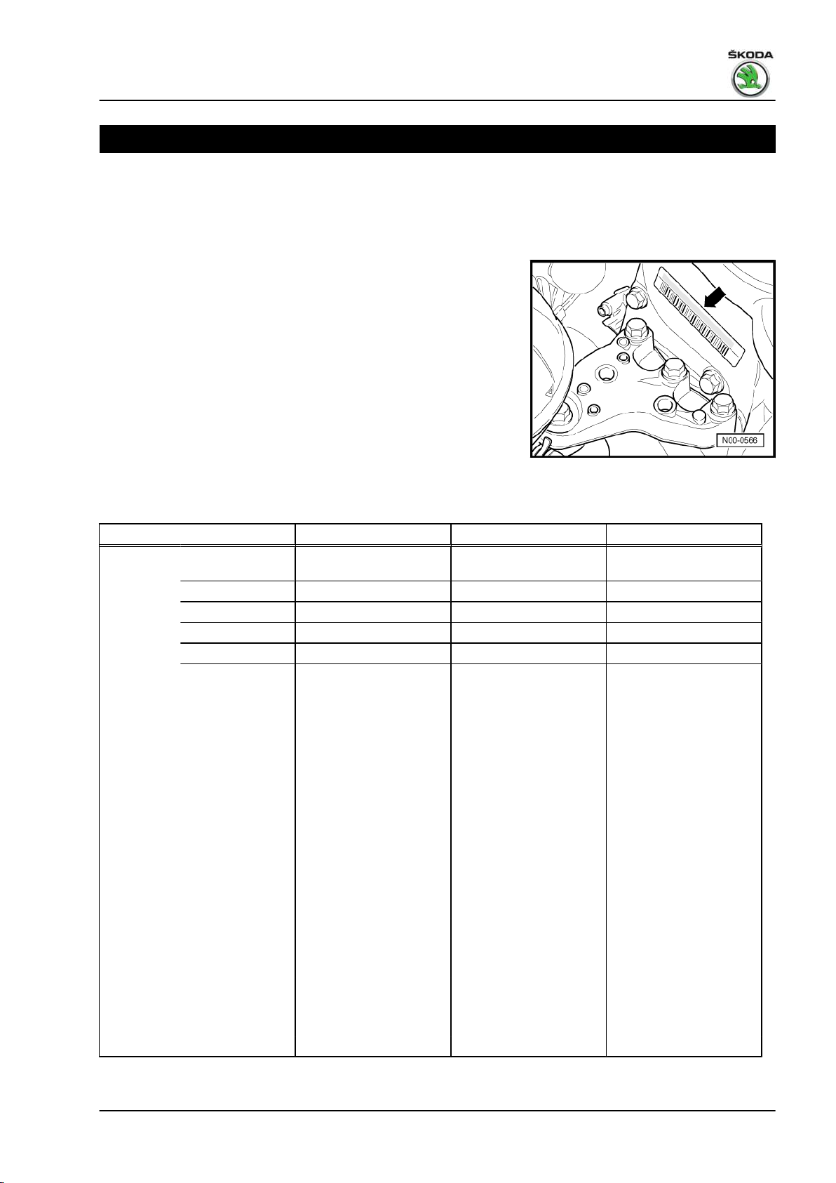
1.1 Engine number
The engine identification characters and the engine number can
be found on the sticker -arrow- at the timing case.
In addition, the engine identification characters are indicated on
the vehicle data sticker and also at the front on the cylinder block
on the connecting flange for gearbox.
The engine number consists of 9 characters. The first part repre‐
sents the “engine code” (a maximum of 3 identification letters),
the second part the “serial number”. If more than 999.999 engines
with the same engine code were produced then the first digit of
the six part section will be replaced by a letter.
1.2 Engine characteristics
Edition 03.2014; version 4.0
Identification characters BTS CFNA CLSA
Manufac‐
tured
Exhaust limit values conform‐
ing to
Displace‐
ment
Power out‐
put
Torque Nm at rpm 153/3800 153/3800 153/3800
Bore ∅ mm 76.5 76.5 76.5
Stroke mm 86.9 86.9 86.9
Compres‐
sion
Cylinder / valves per cylinder 4/4 4/4 4/4
Fuel - RON min.
Ignition system, fuel injection Motronic ME 7.5.20 Magneti Marelli 7GV Magneti Marelli 7GV
Firing order 1-3-4-2 1-3-4-2 1-3-4-2
Knock control yes yes yes
Self-diagnosis yes yes yes
Lambda control yes yes yes
Catalytic converter yes yes yes
Balancing shaft no no no
Exhaust gas recirculation no no no
Fabia II 04.07 ► 07.10 06.10 ► 08.10 ►
Roomster 05.06 ► 07.10 06.10 ►
Rapid NH
Rapid NK
Rapid NA
kW at rpm 77/5600 77/5600 77/5600
cm
EU-4, EU-2 DDK EU-4, EU-2 DDK EU-4 IND (BS4)
3
unleaded 95
1598 1598 1598
10.5 : 1 10.5 : 1 10.5 : 1
1)
02.13 ►
03.14 ►
unleaded 95
1)
unleaded 95
09.11 ►
1)
1. Technical data 1
Page 8

Fabia II 2007 ➤ , Fabia II 2009 ➤ , Fabia II 2011 ➤ , Rapid India 2011 ...
1.6/77 kW MPI engine - Edition 03.2014
1)
At least 91 RON in exceptional cases; although engine output
is reduced.
2 Rep. gr.00 - Technical data
Page 9
Fabia II 2007 ➤ , Fabia II 2009 ➤ , Fabia II 2011 ➤ , Rapid India 2011 ...
1.6/77 kW MPI engine - Edition 03.2014
01 – Self-diagnosis
1 Self diagnosis, safety measures,
cleanliness regulations, directions
1.1 Self-diagnosis
This Rep.-Gr. is deleted.
For this use “Vehicle self-diagnosis”, “Measuring method” and
“Fault finding” ⇒ Vehicle diagnostic tester.
1.2 Safety precautions when working on the fuel supply system
WARNING
The fuel feed line is pressurized! Place a clean cleaning cloth
around the connection point before detaching wiring. Reduce
pressure by carefully removing the wiring.
WARNING
When undertaking all assembly work, particularly in the engine
compartment due to its cramped construction, please observe
the following:
♦ Lay lines of all kinds (e.g. fuel, hydraulic fluid, the activated
charcoal container system, cooling fluid and refrigerant,
brake fluid, vacuum) and electrical lines in such a way that
the original line guide is re-established.
♦ Ensure that there is adequate free access to all moving or
hot components.
When removing and installing the fuel gauge sender or the fuel
delivery unit from a full or partly filled fuel tank, pay attention to
the following points:
♦ The extraction hose of an exhaust extraction system which is
switched on, must be positioned close to the assembly open‐
ing of the fuel tank in order to extract the released fuel vapours,
even before the work is commenced. If no exhaust extraction
system is available, a radial fan (motor not in air flow of fan)
with a delivery volume of more than 15 m3/h must be used.
♦ Avoid skin contact with fuel! Wear fuel-resistant gloves!
1. Self diagnosis, safety measures, cleanliness regulations, directions 3
Page 10
Fabia II 2007 ➤ , Fabia II 2009 ➤ , Fabia II 2011 ➤ , Rapid India 2011 ...
1.6/77 kW MPI engine - Edition 03.2014
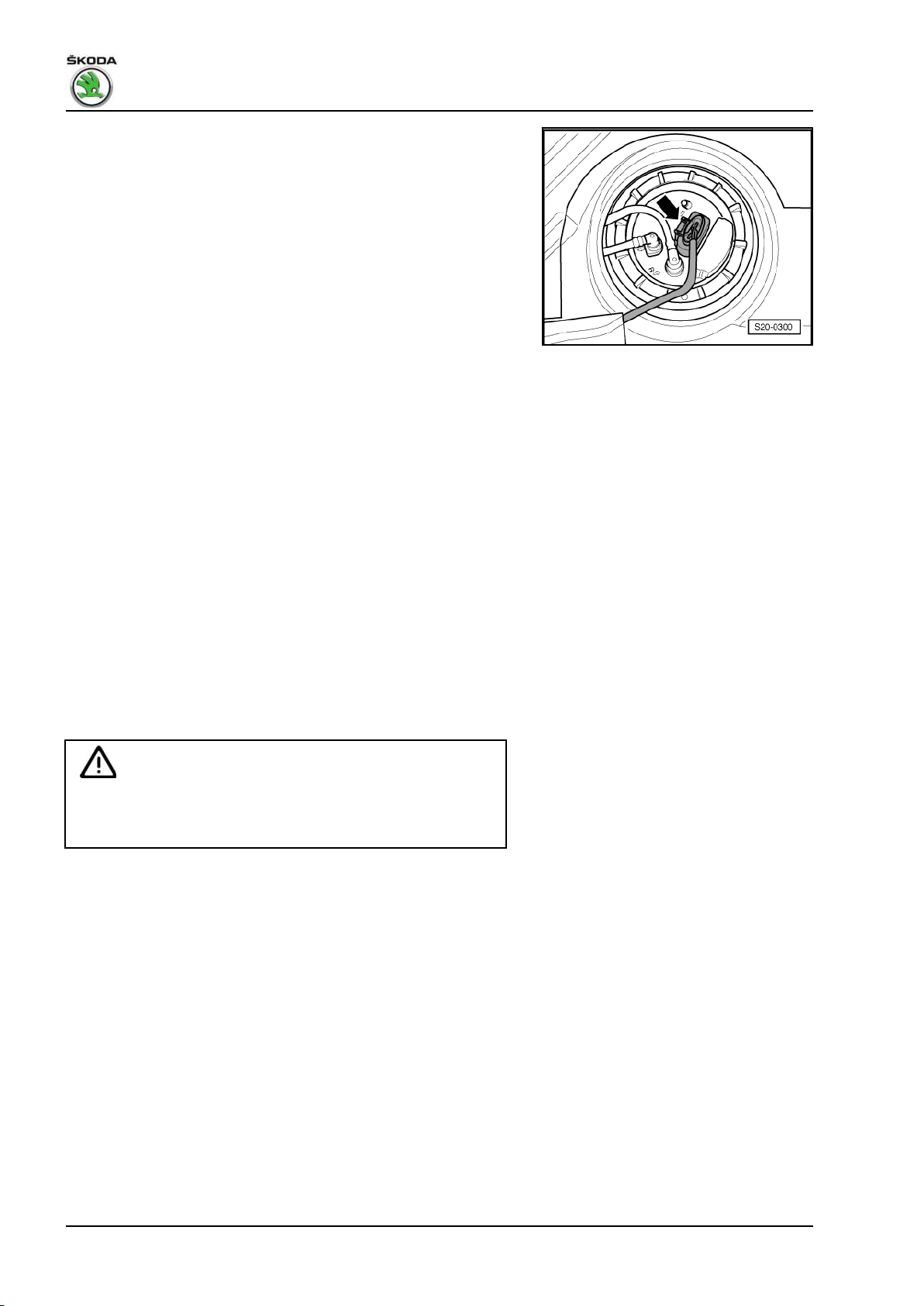
♦ The fuel delivery unit is activated when the ignition is switched
on and by the door contact switch of the driver door. For safety
reasons, before opening the fuel system and in the event that
the battery is not disconnected, the plug -arrow- must be dis‐
connected from the fuel delivery unit or the fuse for the voltage
supply of the fuel delivery unit must be pulled out according to
⇒ Current flow diagrams, Electrical fault finding and Fitting lo‐
cations.
1.3 Rules of cleanliness to observe when working on the fuel supply system
Pay careful attention to the following rules of cleanliness when
working on the fuel supply or fuel injection systems:
♦ Thoroughly clean the connection points and their surroundings
before releasing.
♦ Place removed parts on a clean surface and cover. Do not use
fuzzy cloths!
♦ Carefully cover or seal opened or removed components if the
repair is not carried out immediately.
♦ Only install clean parts: Remove spare parts from their wrap‐
ping immediately before fitting. Do not use any parts which
have been stored unwrapped (e.g. in tool boxes).
♦ When the system is open: Avoid using compressed air when‐
ever possible. Avoid moving the vehicle.
1.4 Safety measures to apply when working on the fuel injection and ignition system
WARNING
The fuel system is under pressure! Before opening the system
lay cleaning cloths around the connection point. Reduce pres‐
sure by carefully releasing the connection point.
Observe the following points to prevent injury to persons and/or
damage to the injection and ignition system:
♦ Do not touch or remove ignition leads with the engine running
or at start speed.
♦ Ignition must be switched off before disconnecting and re-
connecting the cables of the fuel injection and the ignition
system as well as of the test equipment.
♦ If the engine must be operated at starter speed, without it
starting, e.g. during compression pressure testing: open the
cover on the fuse holder underneath the dash panel and pull
out the fuse for the injection valves - N30, N31, N32, N33⇒ Current flow diagrams, Electrical fault finding and Fitting
locations.
If test and measuring devices are required during test drives ob‐
serve the following:
♦ Always secure the test and measuring devices on the rear seat
and have a second person operate them there.
4 Rep. gr.01 - Self-diagnosis
Page 11
Fabia II 2007 ➤ , Fabia II 2009 ➤ , Fabia II 2011 ➤ , Rapid India 2011 ...
1.6/77 kW MPI engine - Edition 03.2014
♦ If the test and measuring devices are operated from the pas‐
senger seat, the passenger could be injured by the release of
the passenger airbag in the event of an accident.
1.5 General notes on the injection system
♦ The engine control unit is equipped with self-diagnosis. Before
repairs as well as for fault finding first interrogate the fault
memory ⇒ Vehicle diagnostic tester.
♦ Fuel hoses in the engine compartment must be secured with
spring band clamps. The use of clamp-type or screw-type clips
is not allowed.
♦ A minimum voltage of 11.5 V is required for perfect functioning
of the electrical components.
♦ Do not use sealants containing silicone. Traces of silicone el‐
ements drawn in by the engine are not burnt in the engine and
damage the lambda probes.
♦ Certain inspections may cause the control unit to detect and
store a fault. It is therefore necessary to interrogate the fault
memory after having completed all inspections and repairs,
and if necessary delete ⇒ Vehicle diagnostic tester.
Safety measures ⇒ page 4
1.6 General notes on the ignition system
Setting data, spark plugs:
♦ ⇒ Maintenance ; Booklet Fabia II .
♦ ⇒ Maintenance ; Booklet Roomster .
♦ ⇒ Maintenance ; Booklet Rapid NH .
♦ ⇒ Maintenance ; Booklet Rapid NA .
Repairing ignition ⇒ page 183 .
♦ Switch off the ignition before disconnecting and connecting the
battery, as this may damage the 4AV control unit.
♦ The engine control unit and further components are equipped
with self-diagnosis; inspect ⇒ Vehicle diagnostic tester.
♦ A minimum voltage of 11.5 V is required for perfect functioning
of the electrical components.
♦ Certain inspections may cause the control unit to detect and
store a fault. It is therefore necessary to interrogate the fault
memory after having completed all inspections and repairs,
and if necessary delete ⇒ Vehicle diagnostic tester.
Safety measures ⇒ page 4 .
1.7 Supplementary instructions and assem‐
bly work on vehicles with an air condi‐
tioning system
WARNING
Do not open the refrigerant circuit of the air conditioning sys‐
tem.
1. Self diagnosis, safety measures, cleanliness regulations, directions 5
Page 12

Fabia II 2007 ➤ , Fabia II 2009 ➤ , Fabia II 2011 ➤ , Rapid India 2011 ...
1.6/77 kW MPI engine - Edition 03.2014
Note
In order to avoid damage to the condenser as well as to the re‐
frigerant lines and hoses of the air conditioning system, ensure
that the lines and hoses are not over-tensioned, kinked or bent.
Steps which should be taken in order to remove and install the
engine without opening the refrigerant circuit:
– Unscrew the holding clamp(s) on the refrigerent lines
– Remove V-ribbed belt ⇒ page 18 .
– Remove AC compressor ⇒ Heating, Air Conditioning; Rep.
gr. 87 .
– Mount the air conditioning compressor and the condenser in
such a way that the refrigerent lines/hoses are not under ten‐
sion.
6 Rep. gr.01 - Self-diagnosis
Page 13

Fabia II 2007 ➤ , Fabia II 2009 ➤ , Fabia II 2011 ➤ , Rapid India 2011 ...
1.6/77 kW MPI engine - Edition 03.2014
10 – Removing and installing engine
1 Removing and installing engine
Special tools and workshop equipment required
♦ Engine mount - T40075 A♦ Engine mount - MP1-202- for assembly stand - MP9-101♦ Assembly stand - MP9-101♦ Lifting device - MP9-201 (2024 A)♦ Workshop crane , e.g. -V.A.S 6100♦ Catch pan , e.g. -VAS 6208♦ Double ladder
♦ Pliers for spring strap clamps
♦ Wire
♦ Grease - G 000 100♦ Hot screw paste - G 052 112 A3-
1.1 Removing engine
Note
♦
The engine is removed downwards together with the gearbox.
♦
All cable straps that have been loosened or cut open when the
engine was removed must be fitted again in the same locations
when the engine is installed again.
♦
Collect drained coolant in a clean container for reuse or proper
disposal.
♦
Jacking up points for raising the vehicle:
♦ ⇒ Maintenance ; Booklet Fabia II .
♦ ⇒ Maintenance ; Booklet Roomster .
♦ ⇒ Maintenance ; Booklet Rapid NH .
♦ ⇒ Maintenance ; Booklet Rapid NA .
– Observe all safety measures and notes for assembly work on
the fuel supply, injection and ignition system; as well as the
rules for cleanliness ⇒ page 3 .
WARNING
Observe measures when disconnecting the battery ⇒ Electri‐
cal System; Rep. gr. 27 .
– Remove battery and battery tray ⇒ Electrical System; Rep.
gr. 27 .
– Remove air filter housing with air guide ⇒ page 161 .
– Remove the sound dampening system ⇒ Body Work; Rep.
gr. 50 .
1. Removing and installing engine 7
Page 14

Fabia II 2007 ➤ , Fabia II 2009 ➤ , Fabia II 2011 ➤ , Rapid India 2011 ...
1.6/77 kW MPI engine - Edition 03.2014
– Remove the front wheelhouse liners ⇒ Body Work; Rep. gr.
66 .
– Drain coolant ⇒ page 118 .
– Remove the coolant hoses from the radiator to the coolant
regulator housing.
– Pull off coolant hoses from heat exchanger for heating.
– Detach coolant hoses from coolant expansion bottle.
– Disconnect plugs from radiator fan - V7- and from thermos‐
witch for radiator fan - F18- .
– Pull out the fuel feed line -2- (catch the fuel which flows out
with a cleaning cloth) and the vent line -1-. Unlock the quick
coupling and disconnect ⇒ page 138 .
– Seal the lines in order to prevent any dirt from penetrating into
the fuel system.
– Disconnect the vacuum and bleeder hoses from the engine or
from other components.
8 Rep. gr.10 - Removing and installing engine
Page 15

Fabia II 2007 ➤ , Fabia II 2009 ➤ , Fabia II 2011 ➤ , Rapid India 2011 ...
1.6/77 kW MPI engine - Edition 03.2014
– Unplug connector -1- from the engine control unit.
– Unplug connector -2-.
– Unclip cable clip -3- -arrows-.
The engine is removed together with the wiring loom.
– Disconnect all cables for the engine, gearbox and starter mo‐
tor which will get in the way during removal.
Vehicles fitted with a manual gearbox
– Remove shift mechanism from gearbox ⇒ Gearbox; Rep. gr.
34 .
– Remove slave cylinder ⇒ Gearbox; Rep. gr. 30 .
Note
Do not depress the clutch pedal.
Vehicles with automatic gearbox
– Remove shift mechanism from gearbox ⇒ Automatic Gear‐
box; Rep. gr. 37 .
Vehicles with air conditioning
WARNING
Do not open the refrigerant circuit of the air conditioning sys‐
tem.
Note
In order to avoid damage to the AC compressor as well as to the
refrigerant lines and hoses, ensure that the lines and hoses are
not over-tensioned, kinked or bent.
– Remove V-ribbed belt ⇒ page 18 .
– Remove AC compressor from holder ⇒ Heating, Air Condi‐
tioning; Rep. gr. 87 .
– Secure the air-conditioning compressor with attached lines to
the assembly carrier.
Continued for all vehicles
– Remove pre-exhaust pipe:
♦ Fabia II and Roomster vehicles with engine identification char‐
acters BTS ⇒ page 171 .
♦ Fabia II and Roomster vehicles with engine identification char‐
acters CFNA ⇒ page 172 .
♦ Fabia II vehicles with engine identification characters CLSA
⇒ page 174
♦ Rapid NH, NK vehicles with engine identification characters
CFNA ⇒ page 175
♦ Rapid NA vehicles with engine identification characters CLSA
⇒ page 175
1. Removing and installing engine 9
Page 16

Fabia II 2007 ➤ , Fabia II 2009 ➤ , Fabia II 2011 ➤ , Rapid India 2011 ...
1.6/77 kW MPI engine - Edition 03.2014
– Unbolt the pendulum support -arrows-.
– Unscrew drive shaft to the right and left of the gearbox and tie
up ⇒ Body; Rep. gr. 40 .
– First of all tighten the bolt of the engine mount - T40075 A- at
the front on the engine.
– Position the engine mount - T40075 A- in the engine/gearbox
jack - V.A.G 1383 A- .
– Tighten engine mount - T40075 A- at the bolt.
– Screw engine mount - T40075 A- onto cylinder block reverse
side to 20 Nm -arrows-.
– Slightly raise the engine/gearbox unit.
Note
Use double ladder to release the screws for the assembly bracket.
For vehicles with assembly bracket version 1
– Unscrew bolts -1-.
10 Rep. gr.10 - Removing and installing engine
Page 17

Fabia II 2007 ➤ , Fabia II 2009 ➤ , Fabia II 2011 ➤ , Rapid India 2011 ...
1.6/77 kW MPI engine - Edition 03.2014
For vehicles with assembly bracket version 2
– Unscrew nut -3- and disconnect earth lead from engine mount.
– Unscrew bolts -2-.
For all vehicles
– Unscrew screws -arrows- and remove gearbox mount.
Note
♦
Check whether all hose and line connections between engine,
gearbox and body are released.
♦
Carefully lower engine with gearbox in order to avoid damage.
– Pull engine/gearbox unit as far forward as possible and lower
slowly downwards.
1.2 Securing the engine to the assembly stand
Special tools and workshop equipment required
♦ Lifting device - MP9-201 (2024 A)♦ Engine mount - MP1-202- for assembly stand - MP9-101- ,
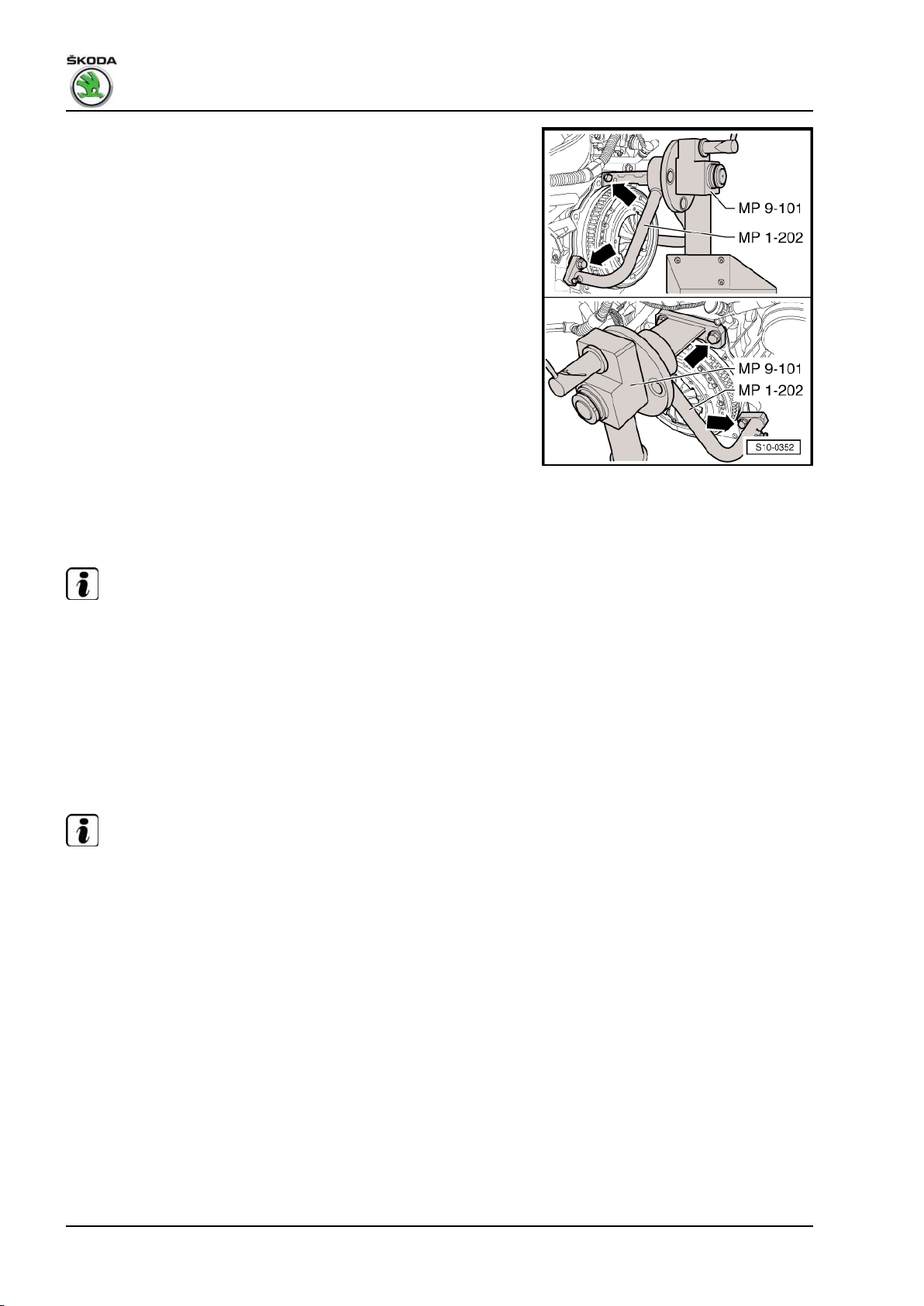
where necessary engine and gearbox jack - VAS 6095♦ Assembly stand - MP9-101♦ Workshop crane , e.g. -V.A.S 6100Secure the engine with engine mount - MP1-202- on the assem‐
bly stand - MP9-101- before performing assembly work.
– Unscrew gearbox from engine:
♦ ⇒ Manual gearbox; Rep. gr. 34 .
♦ ⇒ Automatic gearbox; Rep. gr. 37 .
– Hang lifting device - MP9-201- as follows and slightly raise
engine with the workshop crane .
On the belt pulley side: 2. Hole of the extension in Position 1
On the flywheel side: 1. Hole of the extension in Position 5
WARNING
Use securing pins on the hooks and rig pins -arrows-.
– Remove coolant regulator housing from the cylinder head.
1. Removing and installing engine 11
Page 18
Fabia II 2007 ➤ , Fabia II 2009 ➤ , Fabia II 2011 ➤ , Rapid India 2011 ...
1.6/77 kW MPI engine - Edition 03.2014
– Screw engine mount - MP1-202- to engine and secure to the
assembly stand - MP9-101- .
1.3 Install
Installation is performed in the reverse order, pay attention to the
following points:
Note
♦
When performing installation work replace the self-locking
nuts.
♦
Replace screws which have been tightened to a torquing angle
as well as gasket rings and seals.
♦
All cable straps should be fitted on again in the same place
when installing.
♦
Secure all hose connections with corresponding hose clips.
Vehicles fitted with a manual gearbox
Note
Clean the drive shaft serration and hub serration on used clutch
discs, remove corrosion. Apply a very thin layer of grease - G 000
100- onto the serration. Subsequently move the clutch disc up
and down on the drive shaft until the hub fits smoothly on the shaft.
Remove all excess grease so that it does not get onto the friction
surfaces of the clutch.
– Inspect clutch release bearing for wear, replace if necessary.
– Grease the clutch release bearing and guide bushing for re‐
lease bearing with grease - G 000 100- .
Continued for all vehicles
– Check whether the dowel sleeves for centering the gearbox
are present in the cylinder block, insert if necessary.
12 Rep. gr.10 - Removing and installing engine
Page 19
Fabia II 2007 ➤ , Fabia II 2009 ➤ , Fabia II 2011 ➤ , Rapid India 2011 ...
1.6/77 kW MPI engine - Edition 03.2014
– Insert intermediate plate on sealing flange and push onto the
dowel sleeves -arrows-.
– Install gearbox on engine:
♦ ⇒ Manual gearbox; Rep. gr. 34 .
♦ ⇒ Automatic gearbox; Rep. gr. 37 .
– When swiveling the unit, ensure adequate clearance particu‐
larly to the drive shafts.
– Align the engine and gearbox mounting so that it is stress-free
through tapping movements.
Note
Tightening order and tightening torques of screws for assembly
bracket ⇒ page 14 .
– Install drive shafts ⇒ Chassis; Rep. gr. 40 .
– Install pre-exhaust pipe:
♦ Fabia II and Roomster vehicles with engine identification char‐
acters BTS ⇒ page 171 .
♦ Fabia II and Roomster vehicles with engine identification char‐
acters CFNA ⇒ page 172 .
♦ Fabia II vehicles with engine identification characters CLSA
⇒ page 174
♦ Rapid NH, NK vehicles with engine identification characters
CFNA ⇒ page 175
♦ Rapid NA vehicles with engine identification characters CLSA
⇒ page 175
Vehicles with air conditioning
– Install AC compressor at holder ⇒ Heating, Air Conditioning;
Rep. gr. 87 .
– Install the V-ribbed belt ⇒ page 18 .
Continued for all vehicles
– Electrical connections and proper routing ⇒ Electrical System;
Rep. gr. 97 .
Vehicles fitted with a manual gearbox
– Install slave cylinder ⇒ Gearbox; Rep. gr. 30 .
– Attach shift mechanism ⇒ Gearbox; Rep. gr. 34 .
Vehicles with automatic gearbox
– Attach the selector lever control cable at the gearbox ⇒ Au‐
tomatic gearbox; Rep. gr. 37 .
Continued for all vehicles
– Install air filter housing ⇒ page 161 .
– Top up coolant ⇒ page 118 .
– Adapt the engine control unit to the throttle valve control unit
- J338- ⇒ Vehicle diagnostic tester.
– Interrogate fault memory, rectify any faults existing and erase
the fault memory ⇒ Vehicle diagnostic tester.
– Perform a test drive.
1. Removing and installing engine 13
Page 20
Fabia II 2007 ➤ , Fabia II 2009 ➤ , Fabia II 2011 ➤ , Rapid India 2011 ...
1.6/77 kW MPI engine - Edition 03.2014
– Interrogate fault memory, rectify any faults existing and erase
the fault memory ⇒ Vehicle diagnostic tester.
1.3.1 Tightening torques
Component
Screws and nuts M6 9
deviations:
Fixing screws of engine/gearbox:
♦ ⇒ Manual gearbox; Rep. gr. 34 .
♦ ⇒ Automatic gearbox; Rep. gr. 37 .
Screws for assembly bracket ⇒ page 14 .
M7 13
M8 20
M10 40
M12 70
Nm
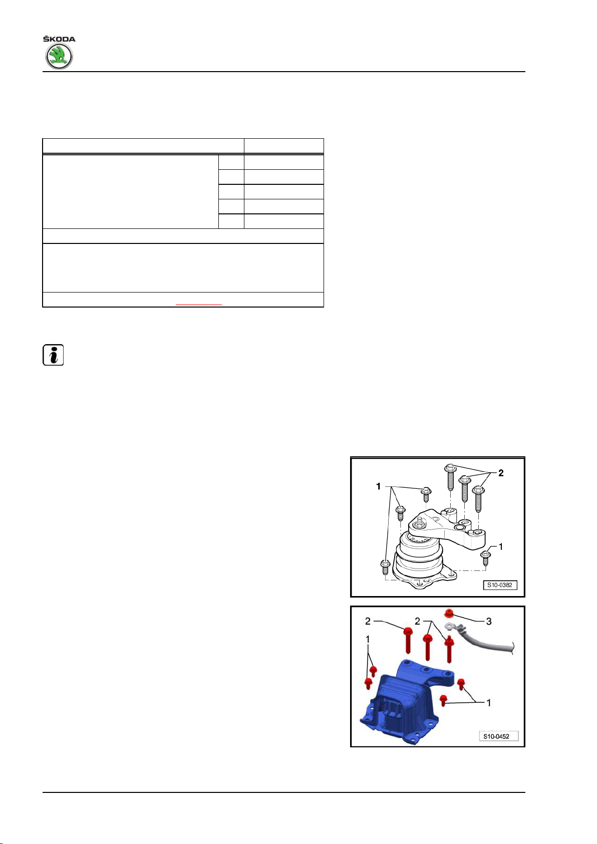
1.4 Assembly bracket
Note
♦
During installation, first insert all bolts for the bearing and tight‐
en by hand at least 2 - 3 turns.
♦
Tighten screws for bracket in the sequence according to the
numerical marking in the figures.
1.4.1 Tightening torques
Assembly bracket - engine, version 1
1 - 20 Nm + torque a further 90° (1/4 turn) - replace
2 - 30 Nm + torque a further 90° (1/4 turn) - replace
Assembly bracket - engine, version 2
1 - 20 Nm + torque a further 90° (1/4 turn) - replace
2 - 30 Nm + torque a further 90° (1/4 turn) - replace
3 - 16 Nm
14 Rep. gr.10 - Removing and installing engine
Page 21

Fabia II 2007 ➤ , Fabia II 2009 ➤ , Fabia II 2011 ➤ , Rapid India 2011 ...
1.6/77 kW MPI engine - Edition 03.2014
Assembly bracket - gearbox
Note
Śruby -1- dokręcić w następującej kolejności: od tyłu, z przodu,
następnie od góry.
1 - 50 Nm + torque a further 90° (1/4 turn) - replace
2 - 40 Nm + torque a further 90° (1/4 turn) - replace
Pendulum support
Note
Before tightening the screws -1- press off gearbox in the elonga‐
ted holes of the pendulum support to the front in such a way that
there is maximum distance between the gearbox and the assem‐
bly carrier.
1 - 30 Nm + torque a further 90° (1/4 turn) - replace
2 - 40 Nm + torque a further 90° (1/4 turn) - replace
1. Removing and installing engine 15
Page 22
Fabia II 2007 ➤ , Fabia II 2009 ➤ , Fabia II 2011 ➤ , Rapid India 2011 ...
1.6/77 kW MPI engine - Edition 03.2014
13 – Crankshaft group
1 Cylinder block - Belt pulley side
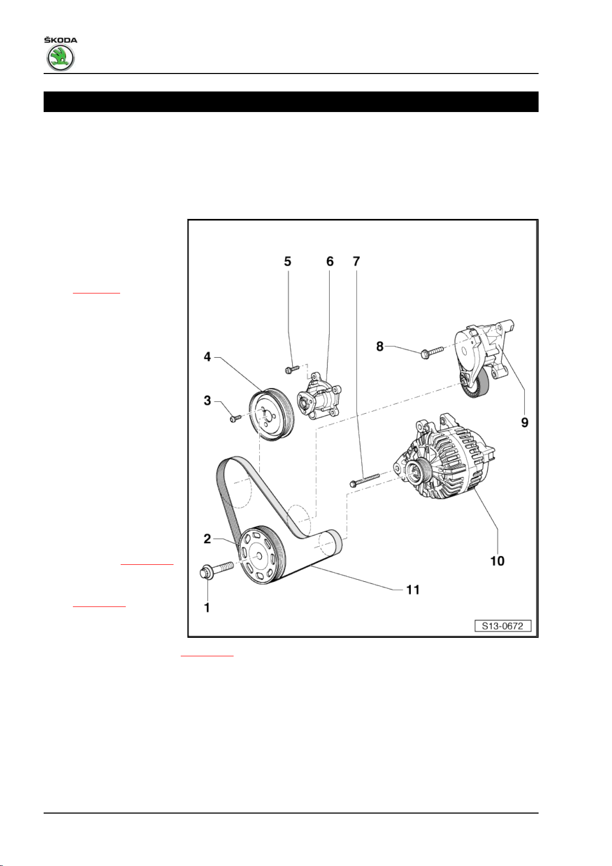
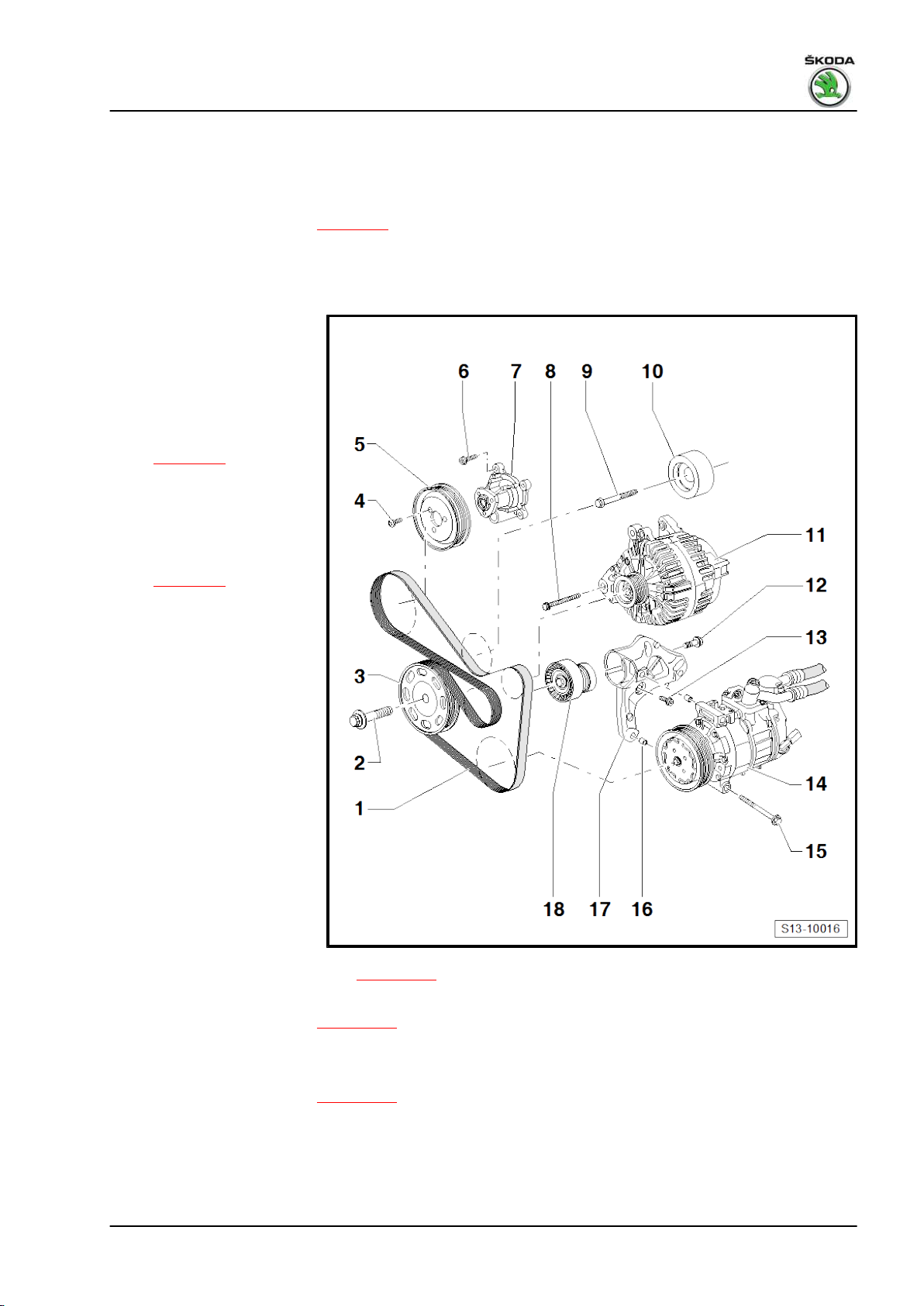
1.1 V-ribbed belt drive - Summary of components
Vehicles without air conditioning
1 - Fixing screw
❑ replace
❑ pay attention to different
version
❑ order of tightening
⇒ page 33
❑ The clamping surface of
the fixing screw must be
free of grease and oil.
❑ When loosening and
tightening counterhold
the belt pulley with the
counterholder - T30004
(3415)- with bolts T30004/1 (3415/1)- .
2 - Crankshaft-belt pulley
❑ Clamping surfaces must
be free of oil and grease.
3 - 20 Nm
❑ When loosening and
tightening, counterhold
with adapted wrench for
the water pump and
power-assisted steering
- MP1-308- .
❑ Adapt wrench for the
water pump and powerassisted steering MP1-308- ⇒ page 123
4 - Belt pulley for coolant pump
❑ removing and installing
⇒ page 123
5 - 10 Nm
6 - Coolant pump
❑ removing and installing ⇒ page 123
7 - 25 Nm
8 - 23 Nm
9 - Tensioning pulley
❑ swivel tensioning device for V-ribbed belt with open-end wrench to slacken the V-ribbed belt
❑ can be interlocked in released position with locating pin - T10060- or 4 mm hexagon socket wrench.
10 - Generator
❑ removing and installing ⇒ Electrical System; Rep. gr. 27
❑ to facilitate positioning, drive the threaded bushings of the retaining screws at the generator slightly
backwards
16 Rep. gr.13 - Crankshaft group
Page 23
Fabia II 2007 ➤ , Fabia II 2009 ➤ , Fabia II 2011 ➤ , Rapid India 2011 ...
1.6/77 kW MPI engine - Edition 03.2014
11 - V-ribbed belt
❑ mark the direction of rotation with chalk or a felt-tip pen before removing
❑ check for wear
❑ do not kink
❑ removing and installing ⇒ page 18
Vehicles with air conditioning
1 - V-ribbed belt
❑ mark the direction of ro‐
tation with chalk or a felt-
tip pen before removing
❑ check for wear
❑ do not kink
❑ removing and installing
⇒ page 18
2 - Fixing screw
❑ replace
❑ pay attention to different
version
❑ order of tightening
⇒ page 33
❑ The clamping surface of
the fixing screw must be
free of grease and oil.
❑ When loosening and
tightening counterhold
the belt pulley with the
counterholder - T30004
(3415)- with bolts -
T30004/1 (3415/1)- .
3 - Crankshaft-belt pulley
❑ Clamping surfaces must
be free of oil and grease.
4 - 20 Nm
❑ When loosening and
tightening, counterhold
with adapted wrench for
the water pump and
power-assisted steering
- MP1-308- .
❑ Adapt wrench for the
water pump and power-
assisted steering - MP1-308- ⇒ page 123
5 - Belt pulley for coolant pump
❑ removing and installing ⇒ page 123
6 - 10 Nm
7 - Coolant pump
❑ removing and installing ⇒ page 123
1. Cylinder block - Belt pulley side 17
Page 24
Fabia II 2007 ➤ , Fabia II 2009 ➤ , Fabia II 2011 ➤ , Rapid India 2011 ...
1.6/77 kW MPI engine - Edition 03.2014
8 - 25 Nm
9 - 40 Nm
10 - Guide pulley
11 - Generator
❑ removing and installing ⇒ Electrical System; Rep. gr. 27
❑ to facilitate positioning, drive the threaded bushings of the retaining screws at the generator slightly
backwards
12 - 20 Nm + torque a further 90° (1/4 turn)
❑ replace
13 - 25 Nm
14 - AC compressor
❑ removing and installing ⇒ Air conditioning; Rep. gr. 87
15 - 25 Nm
16 - Fitting sleeve
17 - Bracket for AC compressor
18 - Tensioning pulley
❑ swivel with ring spanner to slacken the belt
❑ secure in the untensioned position with locking pin - T10060A- or 4 mm external hex socket
❑ to remove, release screw -Pos. 12-
1.2 Removing and installing V-ribbed belt
Special tools and workshop equipment required
♦ Locking pin - T10060A- or 4 mm hexagon wrench
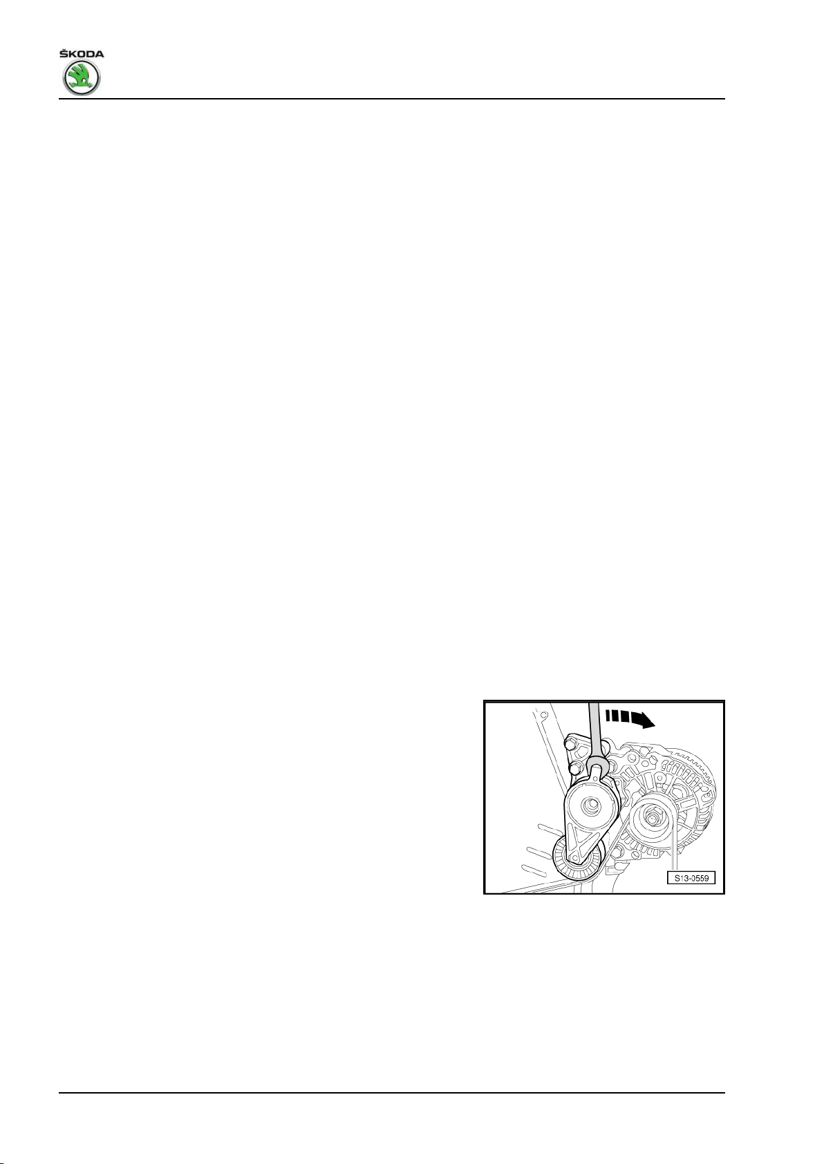
Removing
– Mark the rotation direction of the V-ribbed belt.
Vehicles without air conditioning
– Swivel tensioning pulley with an open-end wrench in
-direction of arrow-.
18 Rep. gr.13 - Crankshaft group
Page 25
Fabia II 2007 ➤ , Fabia II 2009 ➤ , Fabia II 2011 ➤ , Rapid India 2011 ...
1.6/77 kW MPI engine - Edition 03.2014
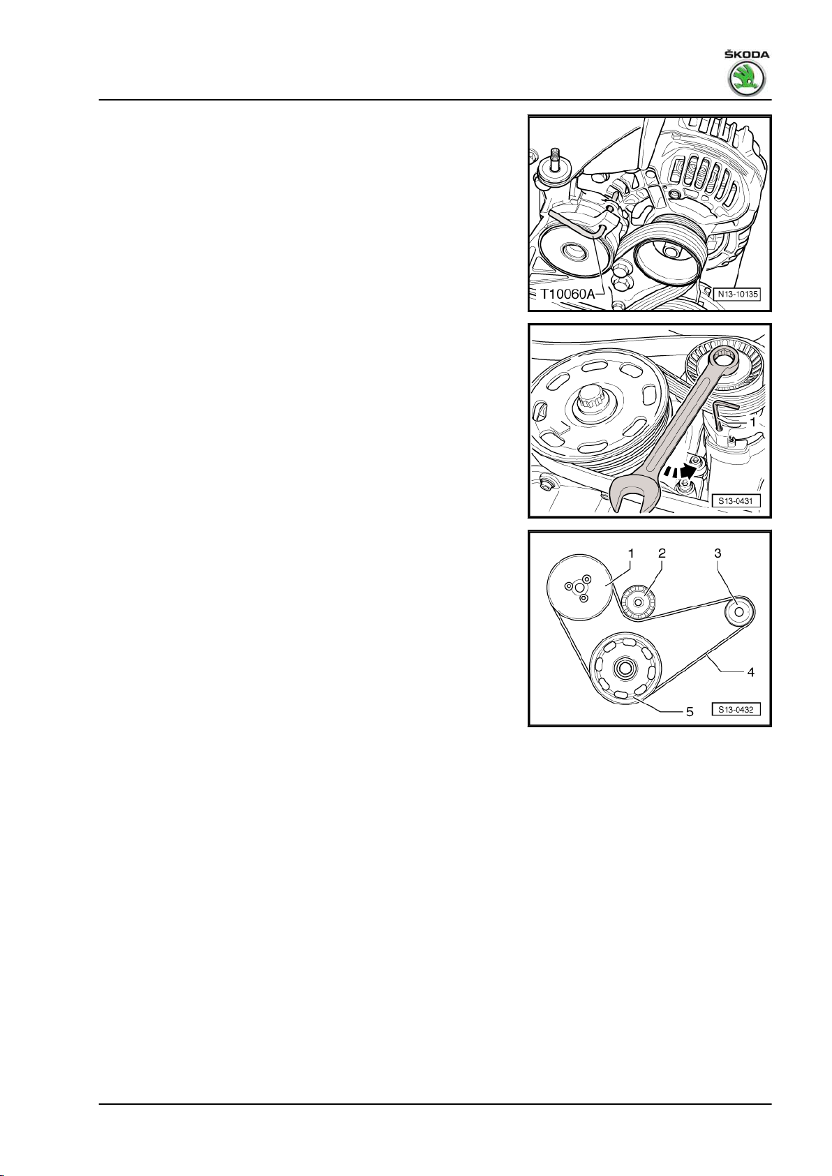
– Lock the tensioning pulley with the locking pin -T10060A- or
with the 4 mm hexagon wrench.
Vehicles with air conditioning
– Swivel tensioning pulley with an open-end wrench in
-direction of arrow-.
– Lock the tensioning pulley with the locking pin -T10060A- or
with the 4 mm hexagon wrench -1-.
Continued for all vehicles
– Remove the release ribbed V-belt.
Install
Installation is performed in the reverse order, pay attention to the
following points:
Routing of the ribbed V-belt - Vehicles without air conditioning
1 - Belt pulley for coolant pump
2 - Tensioning pulley
3 - Belt pulley for AC generator
4 - V-ribbed belt
5 - Crankshaft-belt pulley
1. Cylinder block - Belt pulley side 19
Page 26
Fabia II 2007 ➤ , Fabia II 2009 ➤ , Fabia II 2011 ➤ , Rapid India 2011 ...
1.6/77 kW MPI engine - Edition 03.2014
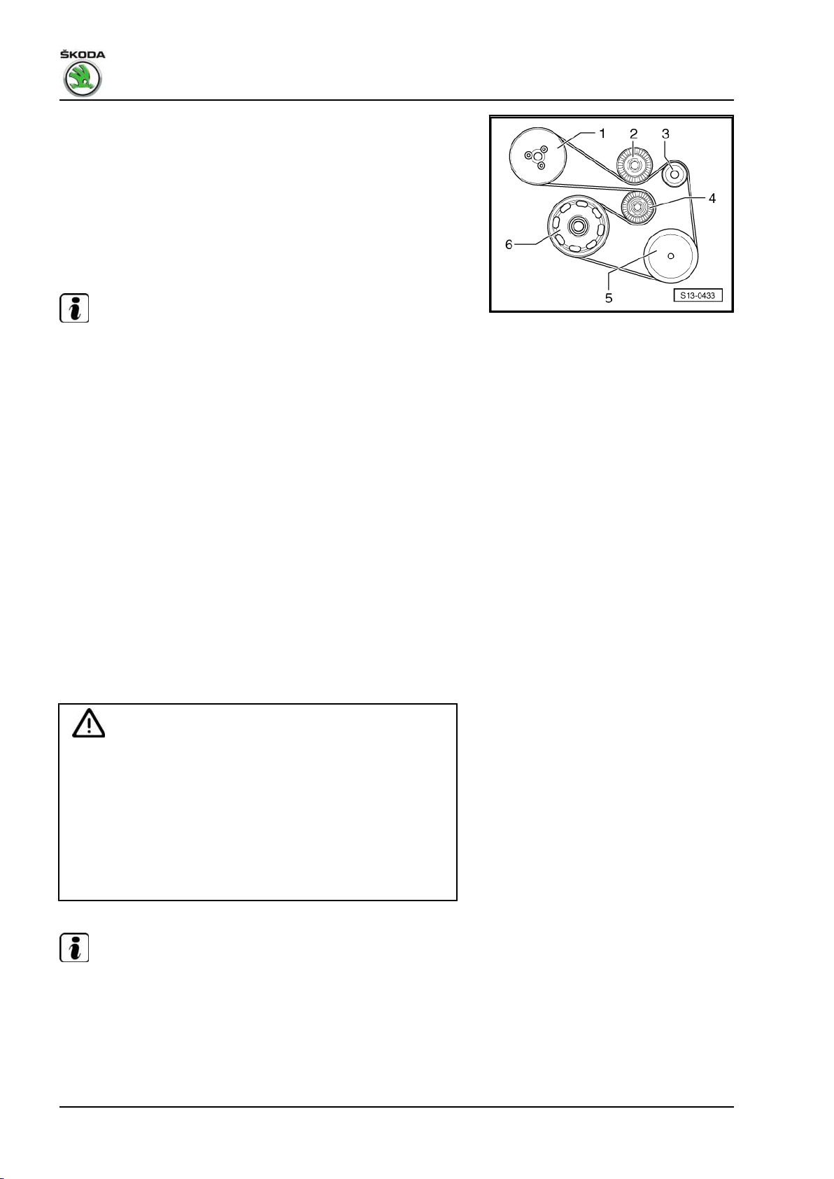
Routing of the ribbed V-belt - Vehicles with air conditioning
1 - Belt pulley for coolant pump
2 - Guide pulley
3 - Belt pulley for AC generator
4 - Tensioning pulley
5 - Belt pulley for AC compressor
6 - Crankshaft-belt pulley
Note
♦
Before fitting the V-ribbed belt make sure that all assemblies
(generator, coolant pump, if necessary AC compressor) belt
pulleys, tensioning and guide rollers are securely mounted.
♦
Replace damaged V-ribbed belt.
♦
If the belt is considerably worn it must be replaced.
♦
Do not bend or buckle the belt!
♦
Pay attention to the correct position and rotation direction of
the V-ribbed belt in the belt pulley and rollers when installing
it.
– Lay the V-ribbed belt on the crankshaft belt pulley. Finally lay
the V-ribbed belt on the tensioning pulley.
– Check correct positioning of the ribbed V-belt on the belt pul‐
leys.
– Start engine and check ribbed V-belt run.
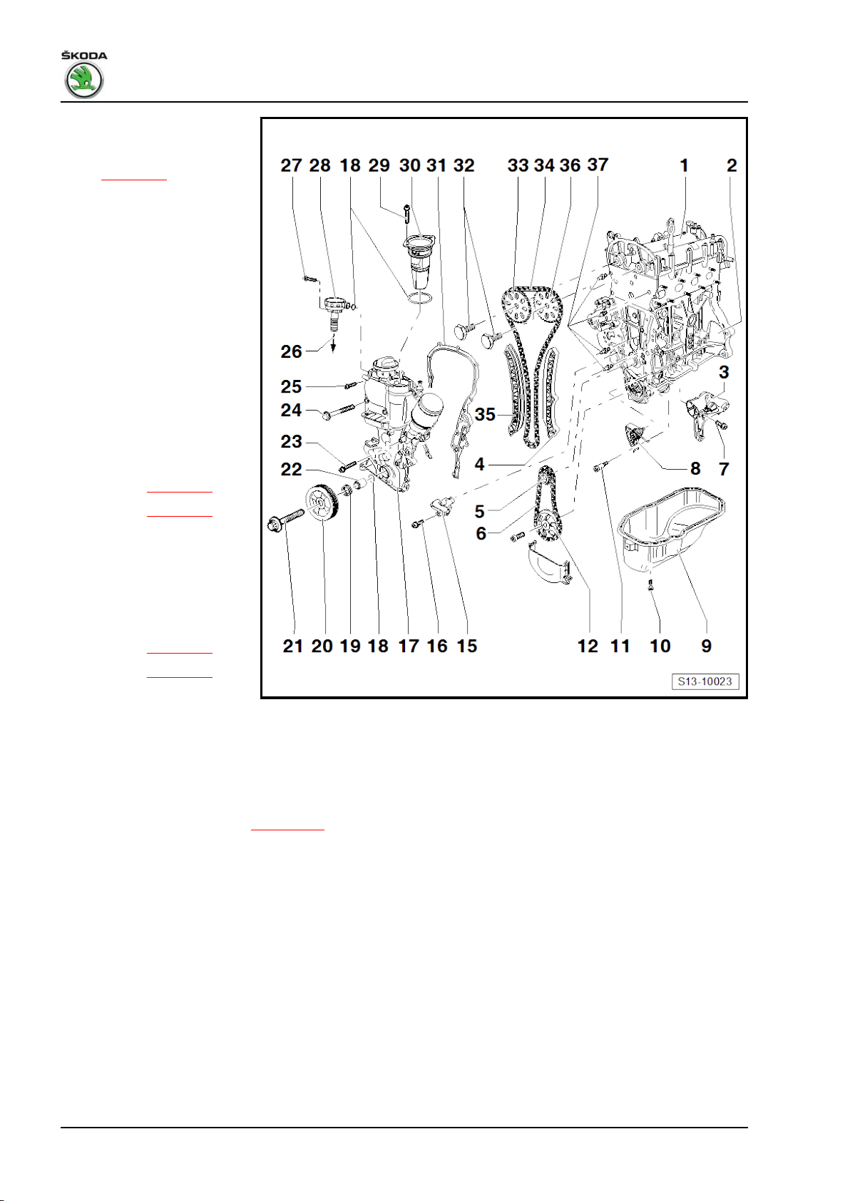
1.3 Camshaft drive - Summary of compo‐
nents
For engine with identification characters BTS
Caution
If considerable quantities of metal swarf or abrasion is found
when carrying out engine repairs, this can be subject to dam‐
age to the crankshaft and conrod bearings. In order to avoid
consequential damage, after the repair perform the following
tasks:
Carefully clean the oil galleries.
Replace engine oil cooler.
Replace oil filter element.
Note
Before assembly oil all bearing and contact surfaces.
20 Rep. gr.13 - Crankshaft group
Page 27

Fabia II 2007 ➤ , Fabia II 2009 ➤ , Fabia II 2011 ➤ , Rapid India 2011 ...
1 - Cylinder head with cam‐
shaft housing
❑ removing and installing
⇒ page 83
❑ Camshaft housing with
integrated camshaft
bearings
2 - Cylinder block
3 - Support
❑ for tensioning pully and
AC compressor
4 - Sliding rail
❑ for timing chain
5 - Sprocket
❑ for oil pump drive and
timing chain
❑ Clamping surfaces must
be free of oil and grease.
❑ removing and installing
⇒ page 67
6 - Drive chain
❑ for oil pump
❑ mark running direction
(installed position) be‐
fore removing
❑ removing and installing
⇒ page 67
7 - 25 Nm
8 - Chain tensioner with ten‐
sioning rail and tensioning
spring
❑ for oil pump drive
❑ Tightening torque: 15 Nm
❑ only be replaced as a complete unit
9 - Oil pan
❑ removing and installing ⇒ page 105
10 - 13 Nm
11 - 15 Nm
12 - Sprocket
❑ for oil pump
❑ Counterhold sprocket with counterholder - T1017213 - Cover
1.6/77 kW MPI engine - Edition 03.2014
14 - 20 Nm + torque a further 90° (1/4 turn)
❑ replace
15 - Chain tensioner
❑ for timing chain
16 - 9 Nm
17 - Timing case
❑ removing and installing ⇒ page 26
❑ to facilitate installation, screw two pin screws -M6 x 80- into the camshaft housing and the cylinder block
1. Cylinder block - Belt pulley side 21
Page 28

Fabia II 2007 ➤ , Fabia II 2009 ➤ , Fabia II 2011 ➤ , Rapid India 2011 ...
1.6/77 kW MPI engine - Edition 03.2014
❑ to better guide the timing case, position the oil pan with two screws
18 - O-ring
❑ replace
❑ in the spacer sleeve -Position 19-
19 - Spacer sleeve
❑ Clamping surfaces must be free of oil and grease.
❑ Fitting position ⇒ page 34
❑ install with new O-ring -Position 18-
20 - Crankshaft-belt pulley
❑ Clamping surfaces must be free of oil and grease.
❑ Removing and installing V-ribbed belt ⇒ page 18
21 - Fixing screw
❑ for crankshaft - belt pulley
❑ replace
❑ The clamping surface of the fixing screw must be free of grease and oil.
❑ insert oiled (thread)
❑ tighten ⇒ page 33
22 - Gasket ring for crankshaft in timing case
❑ replace
❑ replace ⇒ page 32
23 - 10 Nm
❑ M6 x 45mm
24 - 50 Nm
25 - 10 Nm
❑ M6 x 22 mm
❑ insert using locking agent - D 000 600 A226 - To intake manifold
27 - 10 Nm
28 - The vacuum regulating valve (PCV valve)
❑ with ventilation hose
29 - 10 Nm
30 - Oil separator
31 - Gasket
❑ replace
32 - 40 Nm + torque a further 90° (1/4 turn)
❑ replace
❑ Screw with left-hand thread
❑ Counterhold camshaft adjuster with counterholder - T10172-
33 - 50 Nm + torque a further 90° (1/4 turn)
❑ replace
❑ Counterhold sprocket with counterholder - T1017234 - Camshaft adjuster
❑ must not be disassembled
❑ removing and installing ⇒ page 67
22 Rep. gr.13 - Crankshaft group
Page 29

Fabia II 2007 ➤ , Fabia II 2009 ➤ , Fabia II 2011 ➤ , Rapid India 2011 ...
35 - Tensioning rail
36 - Timing chain
❑ removing and installing ⇒ page 67
37 - Sprocket
❑ for exhaust camshaft
❑ removing and installing ⇒ page 67
38 - Guide bushing
39 - Guide bolt
❑ Tightening torque: 18 Nm
1.4 Camshaft drive - Summary of compo‐
nents
For engines with identification characters CFNA and CLSA
Caution
If considerable quantities of metal swarf or abrasion is found
when carrying out engine repairs, this can be subject to dam‐
age to the crankshaft and conrod bearings. In order to avoid
consequential damage, after the repair perform the following
tasks:
1.6/77 kW MPI engine - Edition 03.2014
Carefully clean the oil galleries.
Replace engine oil cooler.
Replace oil filter element.
Note
Before assembly oil all bearing and contact surfaces.
1. Cylinder block - Belt pulley side 23
Page 30
Fabia II 2007 ➤ , Fabia II 2009 ➤ , Fabia II 2011 ➤ , Rapid India 2011 ...
1.6/77 kW MPI engine - Edition 03.2014
1 - Cylinder head with cam‐
shaft housing
❑ removing and installing
⇒ page 83
❑ Camshaft housing with
integrated camshaft
bearings
2 - Cylinder block
3 - Support
❑ for tensioning pully and
AC compressor
4 - Sliding rail
❑ for timing chain
5 - Sprocket
❑ for oil pump drive and
timing chain
❑ Clamping surfaces must
be free of oil and grease.
❑ removing and installing:
♦ Version A ⇒ page 67
♦ Version B ⇒ page 73
6 - Drive chain
❑ for oil pump
❑ mark running direction
(installed position) be‐
fore removing
❑ removing and installing:
♦ Version A ⇒ page 67
♦ Version B ⇒ page 73
7 - 25 Nm
8 - Chain tensioner with tensioning rail and tensioning spring
❑ for oil pump drive
❑ Tightening torque: 15 Nm
❑ only be replaced as a complete unit
9 - Oil pan
❑ removing and installing ⇒ page 105
10 - 13 Nm
11 - 15 Nm
12 - Sprocket
❑ for oil pump
❑ Counterhold sprocket with counterholder - T1017213 - Cover
14 - 20 Nm + torque a further 90° (1/4 turn)
❑ replace
15 - Chain tensioner
❑ for timing chain
24 Rep. gr.13 - Crankshaft group
Page 31

Fabia II 2007 ➤ , Fabia II 2009 ➤ , Fabia II 2011 ➤ , Rapid India 2011 ...
1.6/77 kW MPI engine - Edition 03.2014
16 - 9 Nm
17 - Timing case
❑ Illustration for engine with identification characters CFNA
❑ The illustration of the housing for engine with identification characters CLSA is identical to the illustration
for engine with identification characters BTS
❑ removing and installing ⇒ page 26
❑ to facilitate installation, screw two pin screws -M6 x 80- into the camshaft housing and the cylinder block
❑ to better guide the timing case, position the oil pan with two screws
18 - O-ring
❑ replace
❑ in the spacer sleeve -Position 22-
19 - Gasket ring for crankshaft in timing case
❑ replace
❑ replace ⇒ page 32
20 - Crankshaft-belt pulley
❑ Clamping surfaces must be free of oil and grease.
❑ Removing and installing V-ribbed belt ⇒ page 18
21 - Fixing screw
❑ for crankshaft - belt pulley
❑ replace
❑ The clamping surface of the fixing screw must be free of grease and oil.
❑ insert oiled (thread)
❑ tighten ⇒ page 33
22 - Spacer sleeve
❑ Clamping surfaces must be free of oil and grease.
❑ Fitting position ⇒ page 34
❑ install with new O-ring -Position 18-
23 - 10 Nm
❑ M6 x 45 mm
24 - 50 Nm
25 - 10 Nm
❑ M6 x 22 mm
❑ insert using locking agent - D 000 600 A2-
26 - To intake manifold
27 - 10 Nm
28 - The vacuum regulating valve (PCV valve)
❑ with ventilation hose
29 - 10 Nm
30 - Oil separator
31 - Gasket
❑ replace
32 - 50 Nm + torque a further 90° (1/4 turn)
❑ replace
❑ Counterhold sprocket with counterholder - T10172-
33 - Sprocket
❑ for inlet camshaft
1. Cylinder block - Belt pulley side 25
Page 32

Fabia II 2007 ➤ , Fabia II 2009 ➤ , Fabia II 2011 ➤ , Rapid India 2011 ...
1.6/77 kW MPI engine - Edition 03.2014
❑ removing and installing:
♦ Version A ⇒ page 67
♦ Version B ⇒ page 73
34 - Timing chain
❑ removing and installing:
♦ Version A ⇒ page 67
♦ Version B ⇒ page 73
35 - Tensioning rail
36 - Sprocket
❑ for exhaust camshaft
❑ removing and installing:
♦ Version A ⇒ page 67
♦ Version B ⇒ page 73
37 - Guide bolt
❑ Tightening torque: 18 Nm
1.5 Removing and installing the timing case
Special tools and workshop equipment required
♦ Supporting device - MP9-200 (10-222A)♦ Counterholder - T30004 (3415)♦ Bolt - T30004/1 (3415/1)♦ Sealant remover gasket stripper (bearing code GST, bearing
article no. R 34402), manufacturer Retech s.r.o.
♦ Cleaning and degreasing agent , e.g. -D 009 401 04♦ Protective goggles and gloves
1.5.1 Removing
– Remove the air filter housing ⇒ page 161 .
– Unscrew vacuum regulating valve (PCV valve).
26 Rep. gr.13 - Crankshaft group
Page 33
Fabia II 2007 ➤ , Fabia II 2009 ➤ , Fabia II 2011 ➤ , Rapid India 2011 ...
1.6/77 kW MPI engine - Edition 03.2014
For vehicles Roomster
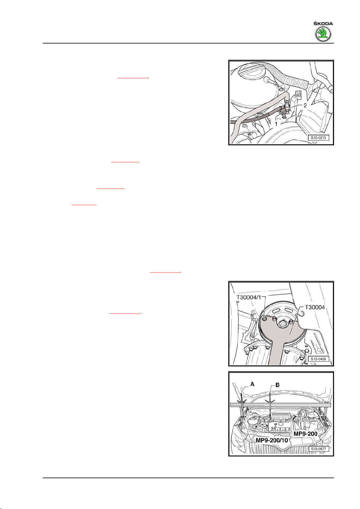
– Pull out the fuel feed line -2- (catch the fuel which flows out
with a cleaning cloth) and the vent line -1-. Unlock the quick
coupling and disconnect ⇒ page 138 .
– Remove activated charcoal filter and bracket.
Continued for all vehicles
– Remove the expansion reservoir and lay it to one side.
The coolant hoses remain connected.
– Remove the sound dampening system ⇒ Body Work; Rep.
gr. 50 .
– Remove the front right wheelhouse liner ⇒ Body Work; Rep.
gr. 66 .
– Remove V-ribbed belt ⇒ page 18 .
For vehicles with air conditioning
– Remove AC compressor with the refrigerant lines connected
from the bracket ⇒ page 16 .
Observe instructions for assembly work on the air-conditioning
system ⇒ page 5 .
– Remove holder for tensioning pulley and V-ribbed belt-guide
pulley.
For vehicles without air conditioning
– Remove tensioning pulley for V-ribbed belt.
Continued for all vehicles
– Remove alternator ⇒ Electrical System; Rep. gr. 27 .
– Remove belt pulley for control pump ⇒ page 123 .
– Remove crankshaft belt pulley.
Counterhold belt pulley with counterholder - T30004- with bolt
- T30004/1- .
– Removing the oil pan ⇒ page 105 .
– Fit supporting device - MP9-200 (10-222A)- .
– Raise engine slightly via spindle -B-, allow spindle -A- to hang
loosely.
1. Cylinder block - Belt pulley side 27
Page 34
Fabia II 2007 ➤ , Fabia II 2009 ➤ , Fabia II 2011 ➤ , Rapid India 2011 ...
1.6/77 kW MPI engine - Edition 03.2014
For vehicles with assembly bracket version 1
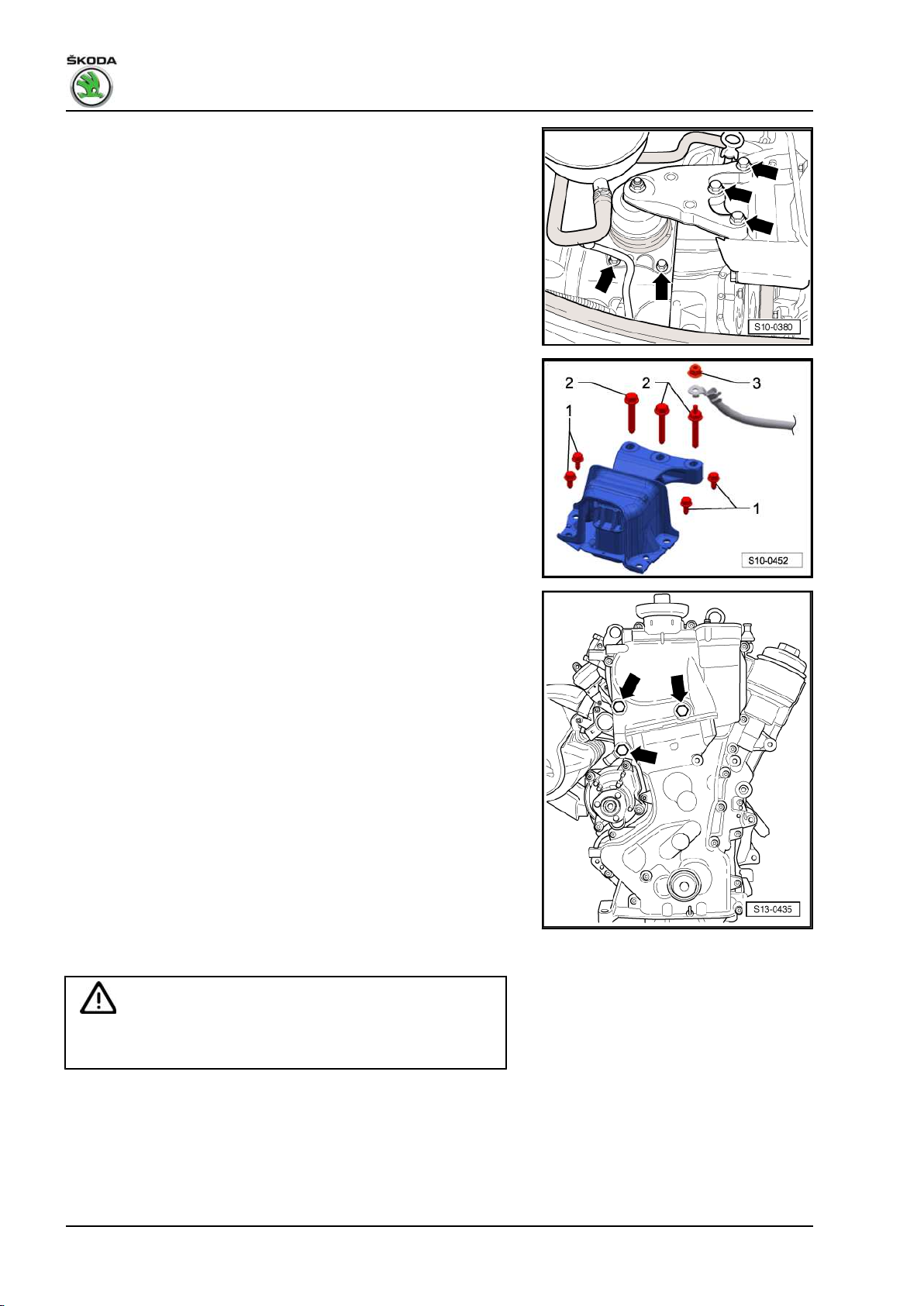
– Screw out screws -arrows- and remove engine mount.
For vehicles with assembly bracket version 2
– Unscrew nut -3- and disconnect earth lead from engine mount.
– Release screws -2 and 1- and remove engine mounting.
For all vehicles
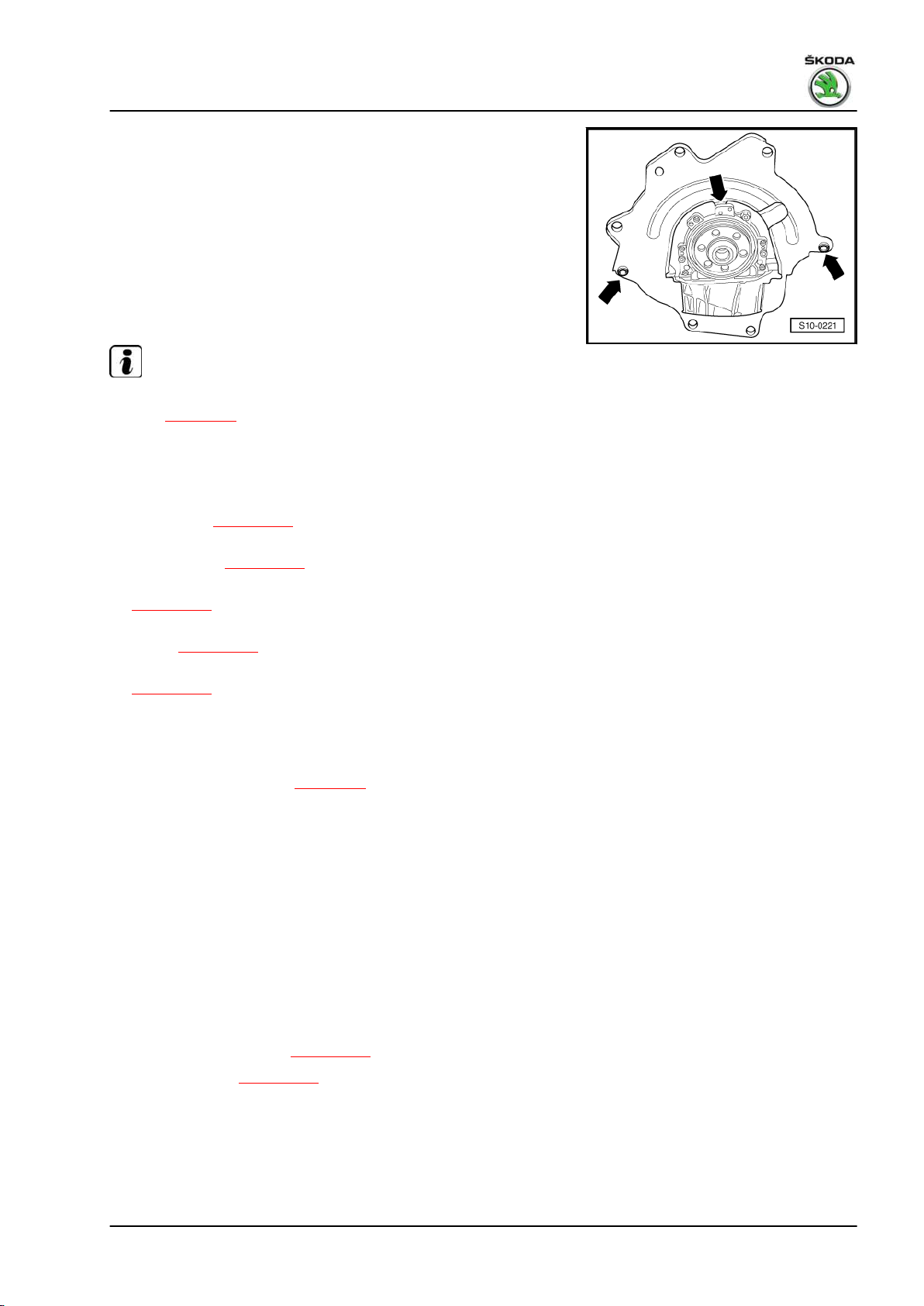
– Release the Allen screws of the control unit and the screws
marked with the -arrows-.
– Remove timing case.
– Remove gasket of timing case.
1.5.2 Install
WARNING
Wear protective gloves when working with sealant and grease
remover!
– Remove gasket residues on sealing surfaces with chemical
sealant remover.
– Degrease the sealing surfaces.
28 Rep. gr.13 - Crankshaft group
Page 35
Fabia II 2007 ➤ , Fabia II 2009 ➤ , Fabia II 2011 ➤ , Rapid India 2011 ...
1.6/77 kW MPI engine - Edition 03.2014
Note
♦
Make sure that the clamping surfaces of the belt pulley, the
fixing screw, the spacer sleeve, the double chain sprocket and
the front crankshaft journal are free of oil and grease.
♦
Make sure that the camshaft housing is not offset or tilted.
– Carefully place the new gasket of the timing case onto the
dowel pins.
– To facilitate installation, screw two pin screws -M6 x 80- into
the cylinder head and the cylinder block.
– Position the timing case onto the pin screws and the dowel
pins.
– Tighten the fixing screws of the timing case diagonally and
evenly:
♦ Tightening torque for screws M6: 10 Nm
♦ Tightening torque for screws M10: 50 Nm
The further assembly is carried out in reverse order to disassem‐
bly. Pay attention to the following:
Note
Install crankshaft belt pulley ⇒ page 33 .
1. Cylinder block - Belt pulley side 29
Page 36
Fabia II 2007 ➤ , Fabia II 2009 ➤ , Fabia II 2011 ➤ , Rapid India 2011 ...
1.6/77 kW MPI engine - Edition 03.2014
2 Cylinder block, sealing flange and fly‐
wheel
2.1 Cylinder block - Summary of components
WARNING
The crankshaft must not be removed. Merely releasing the
crankshaft bearing cover screws will result in deformations of
the bearing seats of the cylinder block. These deformations
reduce the bearing clearance. Even if the bearing shells were
not replaced, the changed bearing clearance may cause dam‐
age to the bearing.
If the bearing cover screws have been released, replace the
complete cylinder block together with the crankshaft.
It is not possible to measure the crankshaft bearing clearance
under workshop conditions.
Note
Repairs to the clutch ⇒ Gearbox; Rep. gr. 30 .
30 Rep. gr.13 - Crankshaft group
Page 37
Fabia II 2007 ➤ , Fabia II 2009 ➤ , Fabia II 2011 ➤ , Rapid India 2011 ...
1.6/77 kW MPI engine - Edition 03.2014
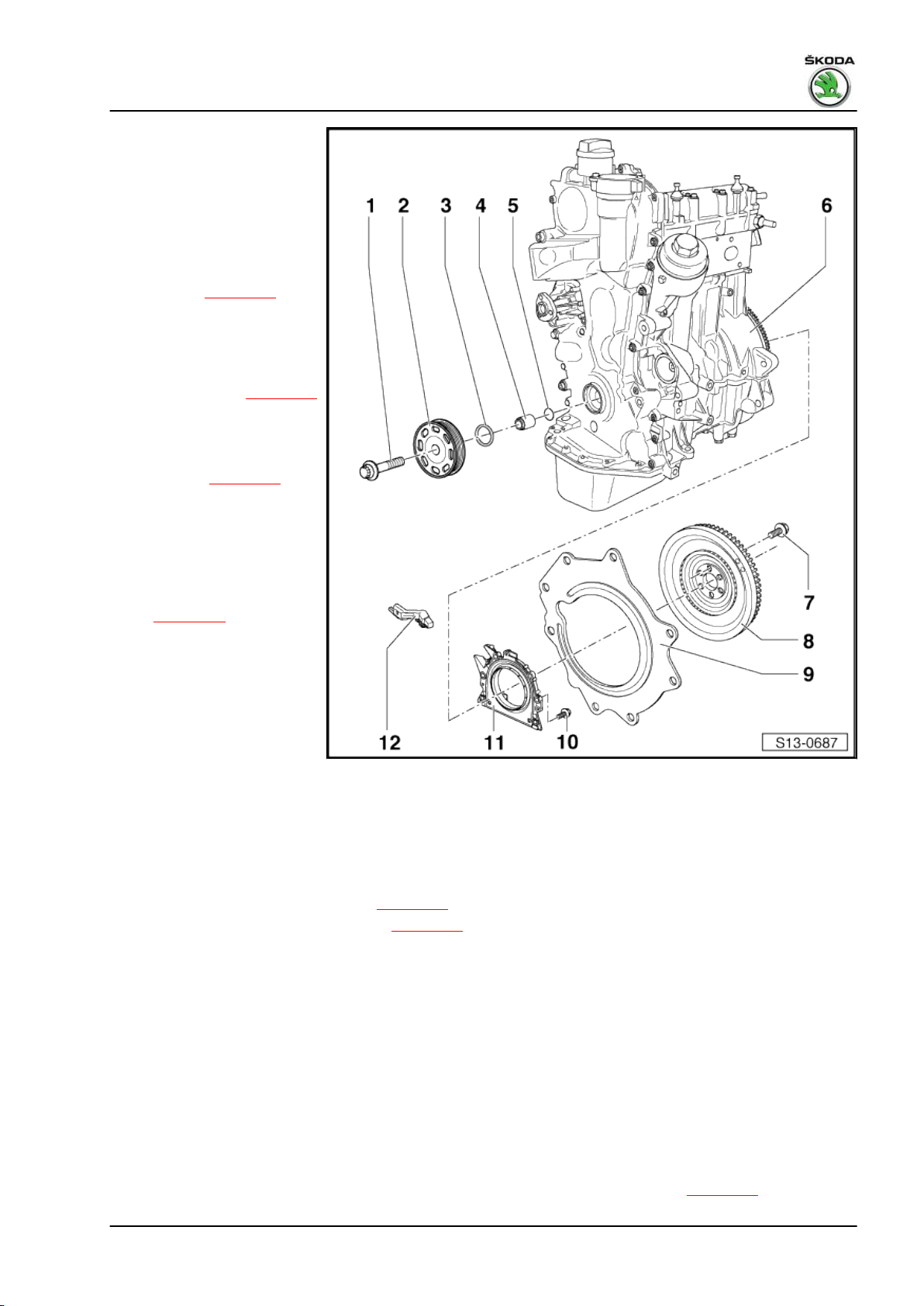
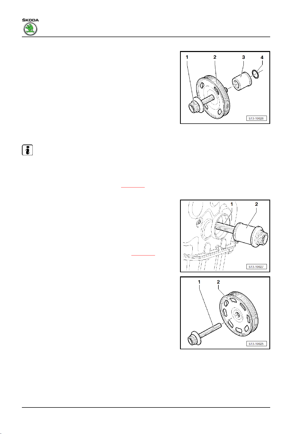
1 - Fixing screw
❑ for crankshaft - belt pul‐
ley
❑ replace
❑ The clamping surface of
the fixing screw must be
free of grease and oil.
❑ insert oiled (thread)
❑ tighten ⇒ page 33
2 - Belt pulley
❑ Clamping surfaces must
be free of oil and grease.
❑ Removing and installing
ribbed V-belt ⇒ page 18
3 - Gasket ring for crankshaft
in timing case
❑ replace
❑ replace ⇒ page 32
4 - Spacer sleeve
❑ Clamping surfaces must
be free of oil and grease.
❑ install with new O-ring
-Position 5-
❑ Fitting position
⇒ page 34
5 - O-ring
❑ replace
❑ in the spacer sleeve
-Position 4-
6 - Cylinder block
❑ Aluminium cylinder
block with timing case
shown for engine with identification characters BTS, CFNA
❑ for engine with identification characters CLSA made of grey cast iron
7 - 60 Nm + torque a further 90° (1/4 turn)
❑ replace
8 - Flywheel/drive plate
❑ removing and installing flywheel ⇒ page 36
❑ removing and installing driver disc ⇒ page 37
9 - Intermediate plate
❑ must be positioned on dowel sleeves
❑ do not damage during assembly work
10 - Screw
❑ replace
❑ Observe part number ⇒ ETKA - Electronic Catalogue of Original Parts
❑
Tighten to tightening torque for engine with grey cast iron block 8 Nm + 90° (1/4 turns)
❑
Tighten to tightening torque for engine with aluminium block 8 Nm + 45° (1/8 turns)
11 - Sealing flange with rotor and gasket ring
❑ always replace complete with rotor and gasket ring
❑ pay attention to different versions for manual gearbox and automatic gearbox ⇒ page 39
2. Cylinder block, sealing flange and flywheel 31
Page 38
Fabia II 2007 ➤ , Fabia II 2009 ➤ , Fabia II 2011 ➤ , Rapid India 2011 ...
1.6/77 kW MPI engine - Edition 03.2014
❑ replace the sealing flange for the crankshaft ⇒ page 39
12 - Engine speed sender - G28-
❑ with captive screw
❑ Tightening torque: 5 Nm
❑ Pay attention to the part number
❑ removing and installing ⇒ page 161
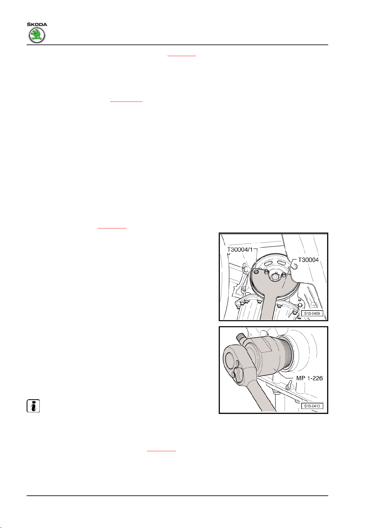
2.2 Replacing crankshaft seal on belt pulley side
Special tools and workshop equipment required
♦ Gasket ring extractor - MP1-226 (3203)♦ Assembly device - T10117♦ Counterholder - T30004 (3415)♦ Bolt - T30004/1 (3415/1)Removing
– Remove the bottom part of the right wheelhouse liner ⇒ Body
Work; Rep. gr. 66 .
– Remove V-ribbed belt ⇒ page 18 .
– Release fixing screw for crankshaft belt pulley.
Counterhold crankshaft belt pulley with counterholder -
T30004 - and bolt - T30004/1- .
– Release the fixing screw and remove the belt pulley from the
crankshaft.
– Unscrew inner part of the gasket ring extractor - MP1-226-
three turns (approx. 5 mm) out of the outer part and lock with
knurled screw.
– Oil the thread head of the gasket ring extractor - MP1-226- ,
position and forcefully screw it into the gasket ring as far as
possible.
– Release knurled screw and turn the inner side against the
crankshaft until the gasket ring is pulled out.
– Remove the spacer sleeve from the crankshaft journal and
clean the clamping surfaces of the crankshaft chain sprocket.
Install
Note
Make sure that the clamping surfaces of the fixing screw, the belt
pulley, the spacer sleeve and the crankshaft chain sprocket are
free of oil and grease.
– Replace the O-ring in the spacer sleeve ⇒ page 34
-Position 4-.
32 Rep. gr.13 - Crankshaft group
Page 39
Fabia II 2007 ➤ , Fabia II 2009 ➤ , Fabia II 2011 ➤ , Rapid India 2011 ...
1.6/77 kW MPI engine - Edition 03.2014
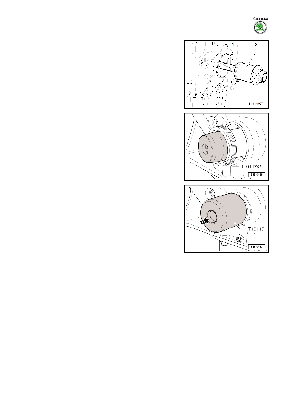
– First of all, slide a new spacer sleeve -2- onto the holding down
bolt -1-.
– Screw the fixing screw -1- by about 2 turns into the crankshaft.
– Slide the spacer sleeve -2- onto the crankshaft journal as far
as it will go.
– Release fixing screw (at the same time press the spacer
sleeve against the crankshaft).
– Position the assembly device - T10117/2- in front of the spacer
sleeve and slide the gasket ring onto the spacer sleeve.
– Remove the assembly device - T10117/2- from the spacer
sleeve.
– Press the gasket ring with the assembly device - T10117- by
striking uniformly up to the stop in the timing case.
– Tighten screw for crankshaft belt pulley ⇒ page 33 .
Further installation occurs in a similar way in reverse order to re‐
moval.
2.3 Tightening process of the screw for
crankshaft belt pulley
Special tools and workshop equipment required
♦ Counterholder - T30004 (3415)♦ Bolt - T30004/1 (3415/1)-
2. Cylinder block, sealing flange and flywheel 33
Page 40
Fabia II 2007 ➤ , Fabia II 2009 ➤ , Fabia II 2011 ➤ , Rapid India 2011 ...
1.6/77 kW MPI engine - Edition 03.2014
Conditions
• Timing o.k.
• Gasket ring for crankshaft in timing case removed.
Fitting position of the spacer sleeve
1 - Fixing screw
2 - Crankshaft-belt pulley
3 - Spacer sleeve
4 - O-ring in the spacer sleeve
– Remove camshaft housing plastic cover and intake hose to air
filter housing.
– Remove cap of outlet camshaft. Collect any engine oil which
flows out with a cloth.
Note
Observe that all clamping surfaces of the fixing screw for the
crankshaft belt pulley to the crankshaft chain sprocket are free of
oil and grease.
– Replace the O-ring in the spacer sleeve ⇒ page 34
-Position 4-.
– First of all, slide the spacer sleeve -2- onto the holding down
bolt -1-.
– Screw the fixing screw -1- by about 2 turns into the crankshaft.
– Slide the spacer sleeve -2- onto the crankshaft journal as far
as it will go.
– Release fixing screw (at the same time press the spacer
sleeve against the crankshaft).
– Install the new gasket ring for the crankshaft ⇒ page 32 .
– Slightly oil the first third of the thread of the new fixing screw.
– Rotate the new holding down bolt -1- with crankshaft-belt pul‐
ley -2- into the crankshaft journal.
Always use a new fixing screw -1-.
34 Rep. gr.13 - Crankshaft group
Page 41
Fabia II 2007 ➤ , Fabia II 2009 ➤ , Fabia II 2011 ➤ , Rapid India 2011 ...
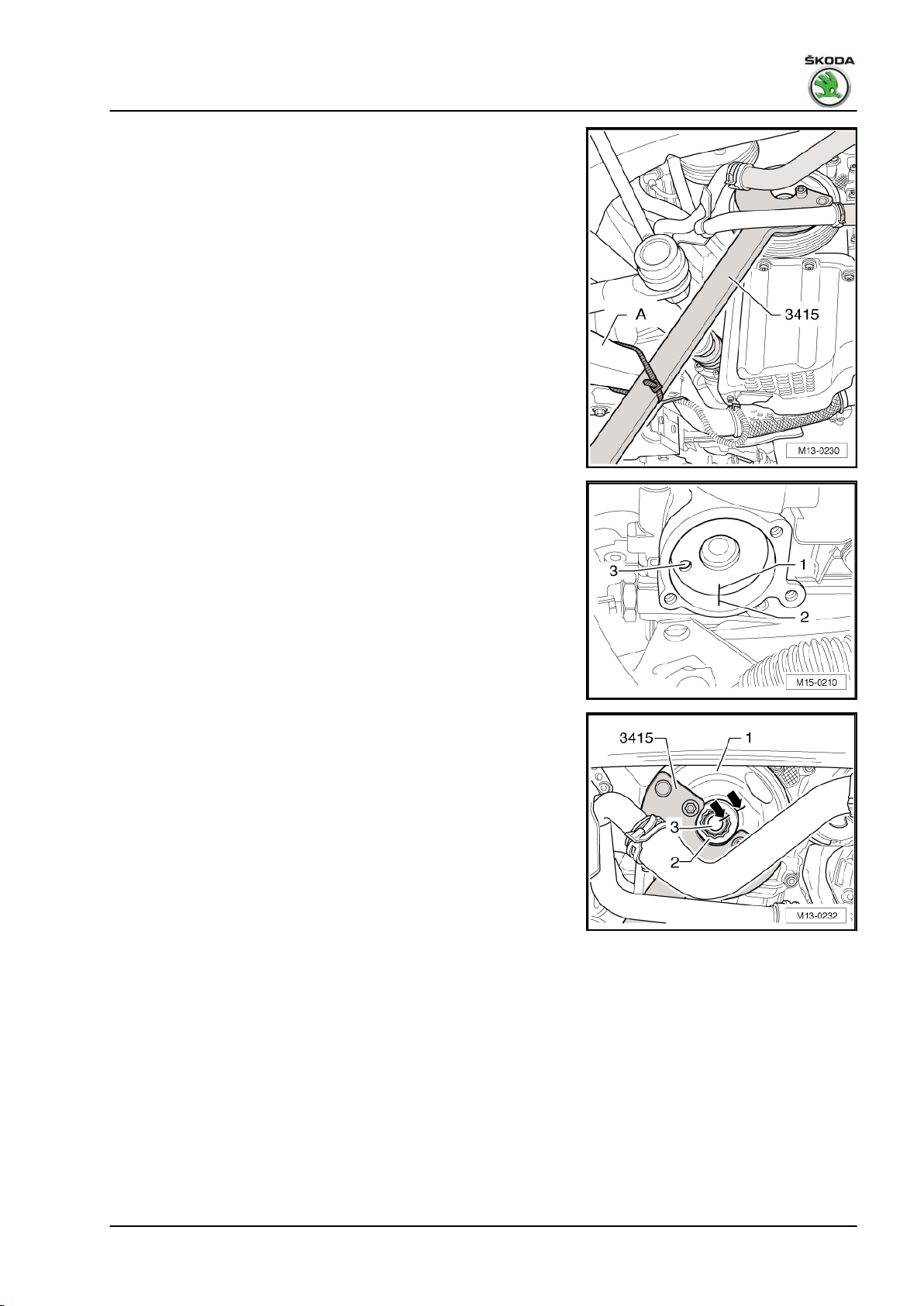
1.6/77 kW MPI engine - Edition 03.2014
– Insert counterholder - 3415- with the bolt - 3415/1- into the
holes of the crankshaft belt pulley, support counterholder at
track control arm -A- and secure in this position with a cable
strap. Tighten cable strap.
– Tighten fixing screw for crankshaft belt pulley to the 1st step
as follows:
Tightening torque: 150 Nm
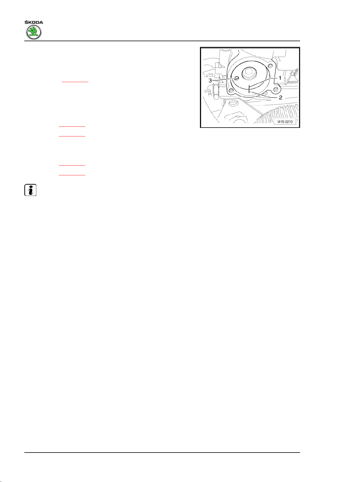
– Now mark the position of the outlet camshaft -1- to the cam‐
shaft housing -2- with a felt-tip pen. The position of the hole
-3- is of no importance for the following inspection.
– Mark at this stage the position of the fixing screw -3- to the
crankshaft belt pulley -1- -arrows-. The marking must not be
performed on the washer -2-, because it does not turn along
when tightening.
– Tighten fixing screw for crankshaft belt pulley to the 2nd step
as follows:
Torque screw a further 180° (1/2 turn).
Tightening may occur in successive stages.
2. Cylinder block, sealing flange and flywheel 35
Page 42
Fabia II 2007 ➤ , Fabia II 2009 ➤ , Fabia II 2011 ➤ , Rapid India 2011 ...
1.6/77 kW MPI engine - Edition 03.2014
– Check the position of the outlet camshaft.
• Both markings -1- and -2- must be aligned.
If both markings -1- and -2- are aligned:
– Test timing ⇒ page 56 .
This checks if the chain sprocket on the crankshaft has turned
along when tightening the screw for the crankshaft belt pulley.
If both markings -1- and -2- are not aligned:
– Test timing:
♦ Version A ⇒ page 56 .
♦ Version B ⇒ page 57 .
If the timing is not correct:
– Setting the timing:
♦ Version A ⇒ page 59 .
♦ Version B ⇒ page 63 .
Note
First of all determine if the peg of the chain sprocket is still in the
slot of the crankshaft.
– If the peg of the chain sprocket is no longer in the slot of the
crankshaft, remove the chain sprocket and inspect for dam‐
age.
Replace the damaged chain sprocket.
If the timing is correct:
The crankshaft has turned to the crankshaft belt pulley.
– Remove crankshaft belt pulley, gasket ring and spacer sleeve.
– Clean all parts thoroughly. They must be free of oil and grease.
– Replace damaged component parts.
– Also throughly clean the clamping surface on the chain sprock‐
et.
– Re-install component parts with new screw for crankshaft belt
pulley.
2.4 Removing and installing flywheel
Special tools and workshop equipment required
♦ Counterholder - MP1-223 (3067)or
♦ Engine mount - MP1-202 (VW 540)♦ Bushing - T30010 (VW 540/1B)♦ Flywheel lock - MP1-504Removing
• Gearbox is removed.
– Remove clutch on vehicles with manual gearbox ⇒ Gearbox;
Rep. gr. 30 .
36 Rep. gr.13 - Crankshaft group
Page 43

Fabia II 2007 ➤ , Fabia II 2009 ➤ , Fabia II 2011 ➤ , Rapid India 2011 ...
1.6/77 kW MPI engine - Edition 03.2014
Engine installed
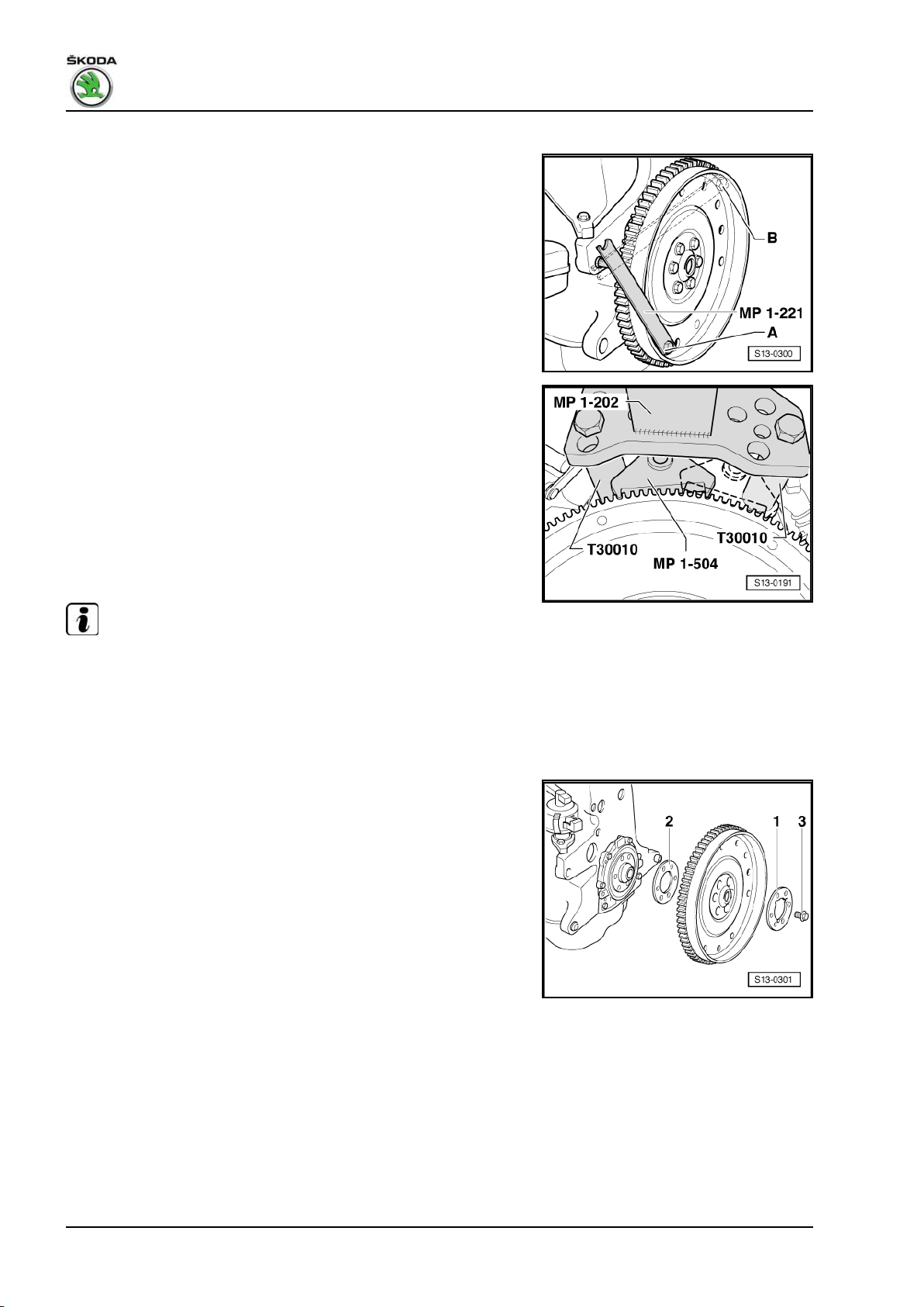
– Insert the counterholder - MP1-223 (3067)- into the bore hole
on the cylinder block.
• Fitting position of the tool:
A - for tightening
B - for slackening
Engine removed
– Position the flywheel lock - MP1-504- on the starter ring gear
of the flywheel disk and turn crankshaft until it rests against
the sleeve - T30010- .
Continued for all
– Release screws and remove flywheel.
Install
Installation is performed in the reverse order, pay attention to the
following points:
Note
Use new screws for attaching.
1. Screw in all the screws by hand.
2. Tighten all the screws crosswise to 60 Nm.
3.
Torque all the screws crosswise a further 90° (1/4 turn).
2.5 Removing and installing drive plate
Special tools and workshop equipment required
♦ Counterholder for clutch - MP1-221 (VW 558)♦ Hexagon screw M8 x 45 and two nuts M10
♦ Depth gauge
or
♦ Engine mount - MP1-202 (VW 540)♦ Bushing - T30010 (VW 540/1B)♦ Flywheel lock - MP1-504Removing
• Gearbox is removed.
2. Cylinder block, sealing flange and flywheel 37
Page 44
Fabia II 2007 ➤ , Fabia II 2009 ➤ , Fabia II 2011 ➤ , Rapid India 2011 ...
1.6/77 kW MPI engine - Edition 03.2014
Engine installed
– Attach counterholder for clutch - MP1-221 (VW 558)- with
M8x45 screw to the drive plate. Place two M10 nuts between
the counterholder and the driver disc.
• Fitting position of the counterholder:
A - for slackening
B - for tightening
Engine removed
– Position the flywheel lock - MP1-504- on the starter ring gear
of the drive plate and turn crankshaft until it rests against the
sleeve - T30010- .
Continued for all
– Release screws and remove drive plate.
Install
Installation is performed in the reverse order, pay attention to the
following points:
Note
Use new screws for attaching.
1. Screw in all the screws by hand.
2. Tighten all the screws crosswise to 60 Nm.
3.
Torque all the screws crosswise a further 90° (1/4 turn).
– Insert the drive plate using the washer with recesses -1-.
– Insert new bolts -3- and tighten to 30 Nm.
38 Rep. gr.13 - Crankshaft group
Page 45

Fabia II 2007 ➤ , Fabia II 2009 ➤ , Fabia II 2011 ➤ , Rapid India 2011 ...
1.6/77 kW MPI engine - Edition 03.2014
– Check dimension -a- in three points and determine the mean
value. Specified value: 19.7...21.3 mm.
Note
The measurement is made through the hole of the drive plate to
the milled surface of the cylinder block.
If the specified value is not reached:
– Remove driver disc and use compensating washer -2-. Tight‐
en screws -3- again to 30 Nm and again check the dimension
-a-.
If the specified value is reached:
–
Tighten screws -3- to 60 Nm and torque a further 90° (1/4 turn)
(the tightening may occur in several stages).
2.6 Replacing the sealing flange for crank‐
shaft - gearbox side
Special tools and workshop equipment required
♦ Assembly fixture - T10017- or -T10134♦ 3 hexagon screws M6 x 35 mm
♦ Feeler gauge
♦ Steel straightedge
2.6.1 Distinguishing features of the sealing
flange of the assembly devices T10017- and -T10134-
Note
♦
Note that different sealing flanges may be installed depending
on what transmission was used ⇒ ETKA - Electronic Cata‐
logue of Original Parts .
♦
Use the corresponding assembly device for the relevant seal‐
ing flange.
2. Cylinder block, sealing flange and flywheel 39
Page 46
Fabia II 2007 ➤ , Fabia II 2009 ➤ , Fabia II 2011 ➤ , Rapid India 2011 ...
1.6/77 kW MPI engine - Edition 03.2014
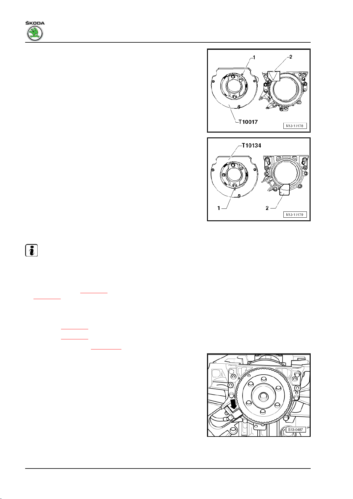
Install sealing flange for automatic gearbox with assembly device
- T100171 - Dowel pin
2 - Transport security (remove immediately before assembly)
Install sealing flange for manual gearbox with assembly device T10134-
1 - Dowel pin
2 - Transport security (remove immediately before assembly)
2.6.2 Removing sealing flange with rotor
Note
These work sequences with the engine removed are shown for
purposes of clear presentation. The work sequences are identical
with the engine installed and gearbox removed.
– Remove flywheel ⇒ page 36 , if necessary drive plate
⇒ page 37 .
– Remove intermediate plate.
– Position crankshaft on TDC for cylinder 1:
♦ Version A ⇒ page 56 .
♦ Version B ⇒ page 57 .
– Removing the oil pan ⇒ page 105 .
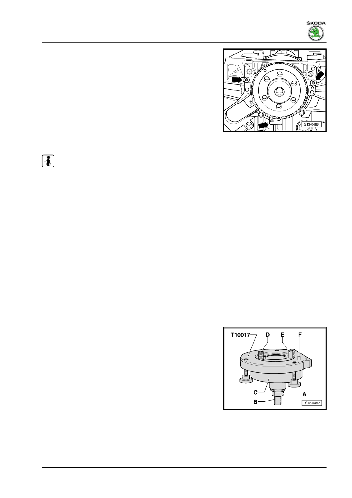
– Remove engine speed sender -arrow-.
– Unscrew the fixing screws of the sealing flange.
40 Rep. gr.13 - Crankshaft group
Page 47
Fabia II 2007 ➤ , Fabia II 2009 ➤ , Fabia II 2011 ➤ , Rapid India 2011 ...
1.6/77 kW MPI engine - Edition 03.2014
– Screw 3 screws M6 x 35 mm into the threaded bores of the
sealing flange -arrows-.
– Press out sealing flange together with rotor from the crank‐
shaft by alternately screwing the screws into the sealing
flange.
2.6.3 Installing sealing flange with rotor
Note
♦
The sealing flange with PTFE gasket ring is provided with
sealing lip supporting ring. This supporting ring is intended as
an assembly sleeve and must not be removed before instal‐
ling.
♦
Do not separate or turn to each other the sealing flange and
rotor after removing them from the spare part package.
♦
The rotor is given its fitting location by positioning the assem‐
bly device - T10017- or - T10134- onto the positioning pin.
♦
The rotor has an elastomer layer on its sealing surface with
the crankshaft. This layer must not be brought into contact with
dirt or grease.
♦
The sealing flange and gasket ring form one unit and must be
replaced together with the rotor.
♦
The fitting location of the assembly device - T10017- , or T10134- to the crankshaft is determined by means of a guide
bolt, which is guided through the threaded bore of the crank‐
shaft.
♦
Unless otherwise indicated, the method for the assembly de‐
vice - T10017- and -T10134- is identical.
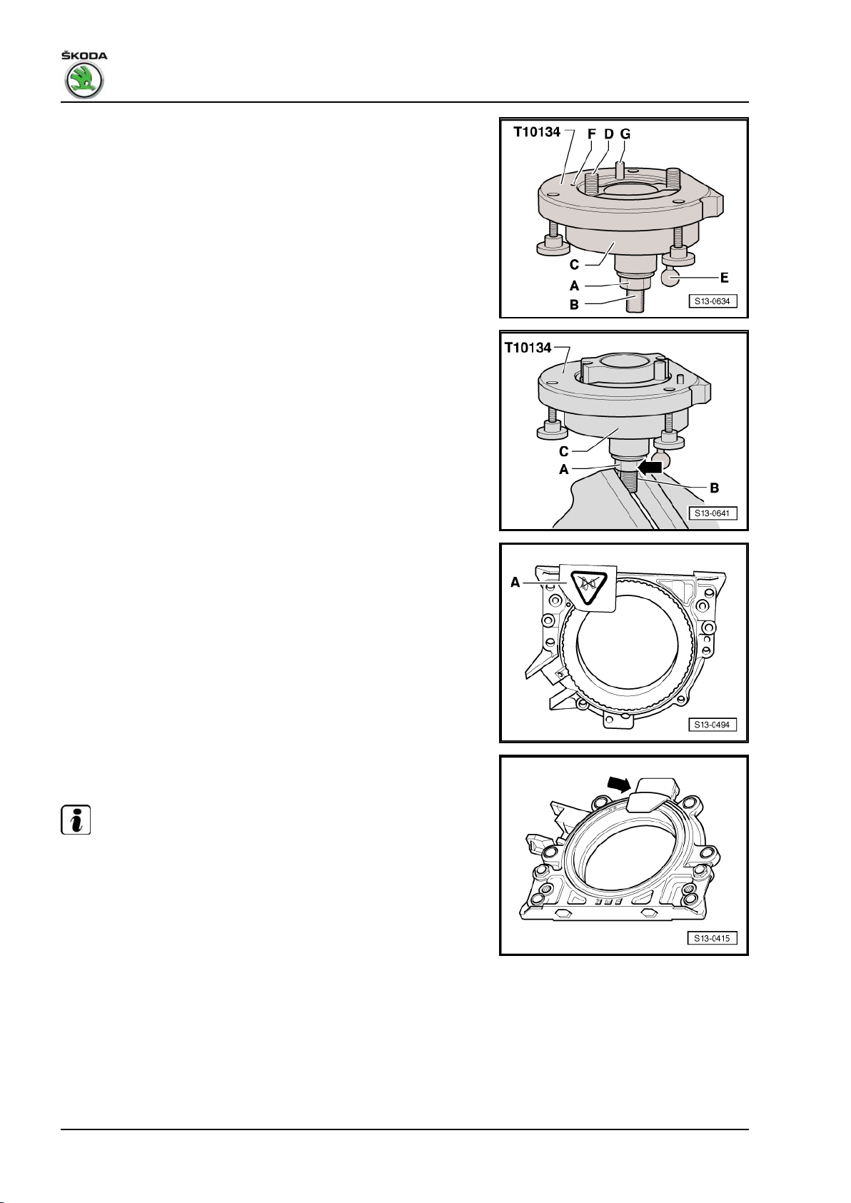
Assembly device - T10017- or -T10134A - Hexagon nut
B - Clamping surface
C - Assembly cup
D - Allan screw
2. Cylinder block, sealing flange and flywheel 41
Page 48
Fabia II 2007 ➤ , Fabia II 2009 ➤ , Fabia II 2011 ➤ , Rapid India 2011 ...
1.6/77 kW MPI engine - Edition 03.2014
E - Guide bolts (for the assembly device - T10134- with red handle
- for petrol engine)
F - Positioning pin
G - Guide bolts (for the assembly device - T10134- with black
handle - for diesel engine)
A - Mounting gasket ring with rotor on the assembly device -
T10017- or -T10134-
– Position nut -A- in the position tightly in front of the clamping
surface -B- and grip assembly device - T10017- or -T10134-
in the vice on the clamping surface -B- of the threaded spindle.
– Remove the securing clip -A- from the new sealing flange for
assembly device - T10017- .
or remove the securing clip -arrow- from the new sealing flange
for assembly device - T10134- .
Note
Do not remove or turn the rotor from the sealing flange.
42 Rep. gr.13 - Crankshaft group
Page 49
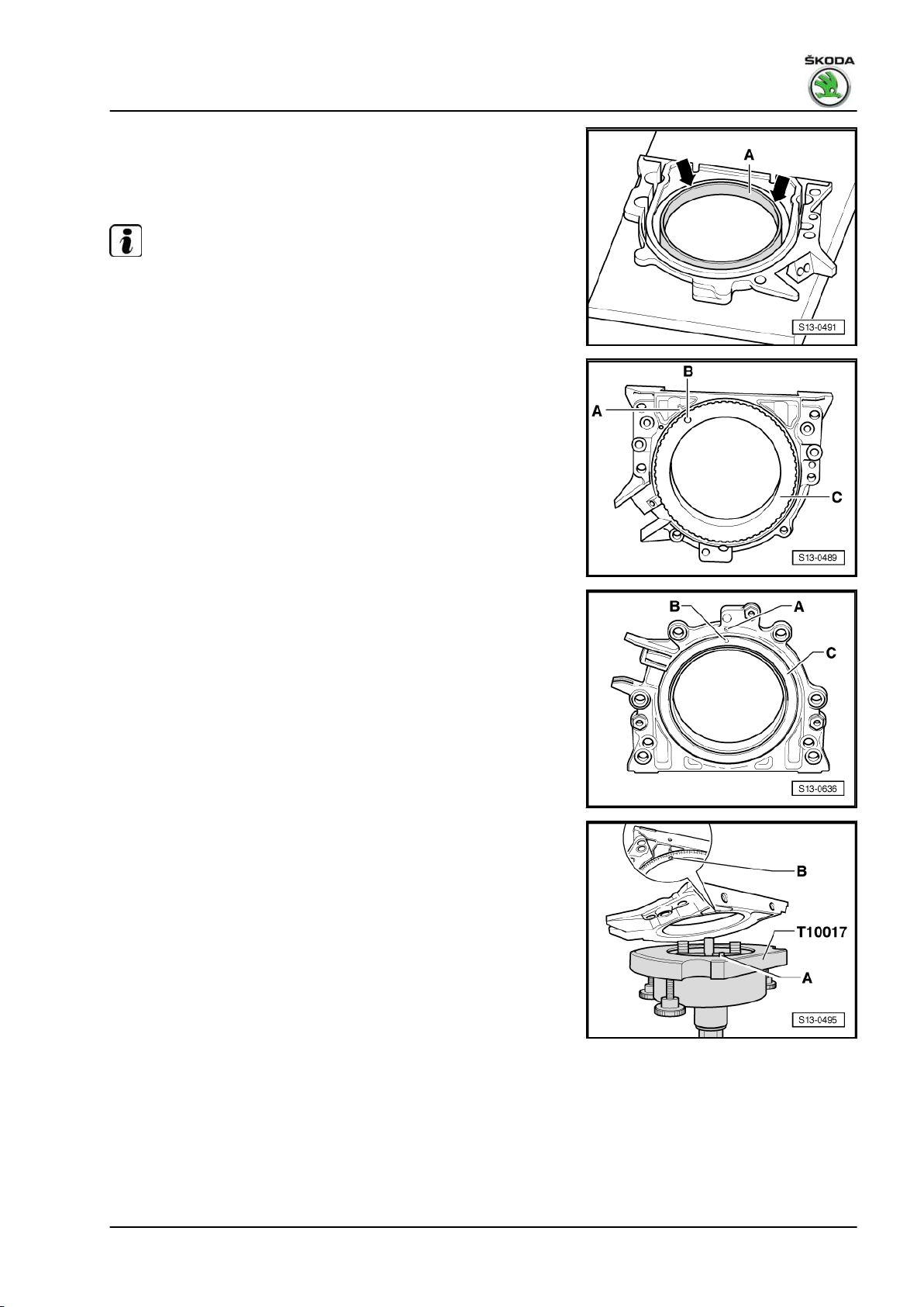
Fabia II 2007 ➤ , Fabia II 2009 ➤ , Fabia II 2011 ➤ , Rapid India 2011 ...
1.6/77 kW MPI engine - Edition 03.2014
– Lay the front side of the sealing flange on a clean and level
surface.
– Press the sealing lip supporting ring -A- -arrows-, until it rests
on the level surface.
Note
The top side of the rotor and the front side of the sealing flange
must be flush.
The locating hole -B- on the rotor -C- must be flush with the mark‐
ing -A- on the sealing flange for assembly device - T10017-
or on the sealing flange for assembly device - T10134- .
– Sealing flange with the front side to the assembly device -
T10017-
2. Cylinder block, sealing flange and flywheel 43
Page 50
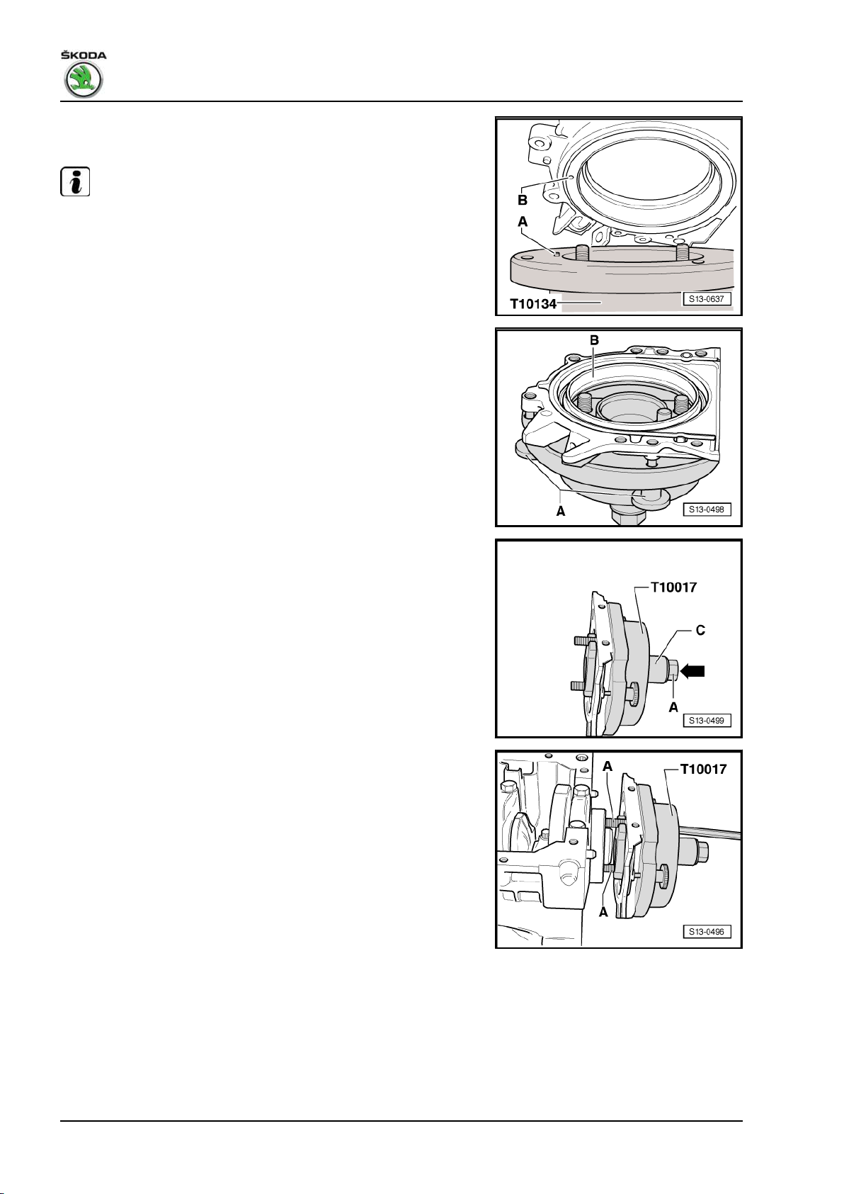
Fabia II 2007 ➤ , Fabia II 2009 ➤ , Fabia II 2011 ➤ , Rapid India 2011 ...
1.6/77 kW MPI engine - Edition 03.2014
or place onto the assembly device - T10134- in such a way that
the positioning pin -A- engages into the hole -B- of the rotor.
Note
Make sure the sealing flange lies flat on the assembly tool.
– When tightening the knurled screws -A- press the sealing
flange and sealing lip supporting ring -B- on the surface of the
assembly device in such a way that the positioning pin can no
longer slide out of the rotor hole.
B - Mounting the assembly device - T10017- or -T10134- with
sealing flange on the crankshaft flange
• The crankshaft flange must be free of grease and oil
• Crankshaft is at TDC for cylinder 1
– Unscrew hexagon nut -A- up to the end of the threaded spin‐
dle.
– Screw assembly tool with Allan screws -A- onto the crankshaft
flange up to the stop.
– Screw in two screws M6 x 35 mm -A- by about 3 thread turns
for the sealing flange guide into the cylinder block.
44 Rep. gr.13 - Crankshaft group
Page 51
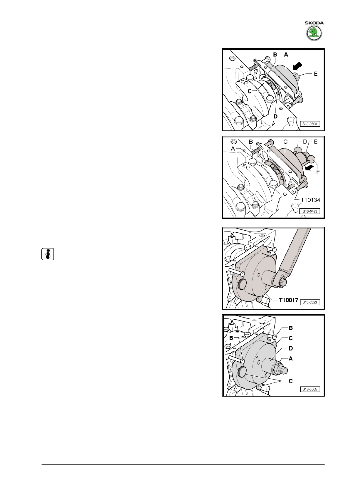
Fabia II 2007 ➤ , Fabia II 2009 ➤ , Fabia II 2011 ➤ , Rapid India 2011 ...
1.6/77 kW MPI engine - Edition 03.2014
For assembly device - T10017– Move the assembly cup -A- by hand in the
-direction of the arrow- until the rotor -B- rests on the crank‐
shaft flange -C-. The guide bolts -D- on assembly device T10017- must at the same time engage into the threaded bore
of the crankshaft. This gives the rotor its final fitting location.
For assembly device - T10134– Move the assembly cup -C- by hand in the
-direction of the arrow- until the rotor -B- rests on the crank‐
shaft flange -A-. Subsequently insert the guide bolt with red
ball -F- fully into the threaded bore of the crankshaft. If the
guide bolt is correctly seated, the handle is approx. 10 mm
from the assembly cup -C-. This gives the rotor its final fitting
location.
C - Pressing the rotor with assembly device - T10017- or -T10134onto the crankshaft flange
– Screw in hexagon nut by hand onto the threaded spindle until
it rests against the assembly cup.
– Tighten the hexagon nut of the assembly device using a torque
wrench with adapter. Tightening torque: 35 Nm.
Note
After tightening the hexagon nut to 35 mm there must still be a
narrow gap between the cylinder block and the sealing flange.
D - Inspecting the fitting position of the rotor on the crankshaft
– Unscrew hexagon nut -A- up to the end of the threaded spin‐
dle.
– Unscrew two M6 x 35 mm screws -B- from the cylinder block.
– Unscrew three knurled screws -C- from the sealing flange.
– Unscrew two Allen screws and remove assembly device -
T10017- or -T10134- .
– Remove sealing lips supporting ring.
2. Cylinder block, sealing flange and flywheel 45
Page 52
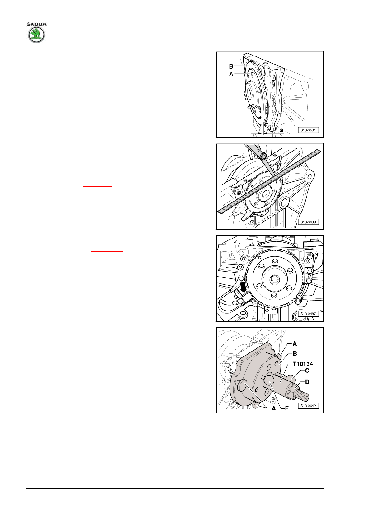
Fabia II 2007 ➤ , Fabia II 2009 ➤ , Fabia II 2011 ➤ , Rapid India 2011 ...
1.6/77 kW MPI engine - Edition 03.2014
The fitting position of the rotor on the crankshaft is accurate if
there is a distance -a- of 0.5 mm between the crankshaft flange
-A- and the rotor -B-.
– Position the steel striaghtedge onto the crankshaft flange.
– Measure the distance between the steel straightedge and the
rotor with a feeler gauge.
If the measured distance is less than 0.5 mm:
– Press down rotor ⇒ page 46 .
If the dimension is correct:
– Tighten the new fixing screws of the sealing alternately cross‐
wise. Tightening torque: 12 Nm.
– Install engine speed sender -arrow-. Tightening torque: 5 Nm.
– Installing the oil pan ⇒ page 105 .
– Installing intermediate plate.
– Install the flywheel or driver disc with new screws.
E - Pressing down the rotor
– Screw assembly device - T10017- or -T10134- with Allan
screws onto the crankshaft flange up to the stop.
– Screw in 3 knurled screws -A- into the flange.
– Subsequently insert the guide bolt with red ball -E- fully into
the threaded bore of the crankshaft. If the guide bolt is correctly
positioned, then the handle has a distance of approx. 10 mm
from the assembly cup -B-.
46 Rep. gr.13 - Crankshaft group
Page 53

Fabia II 2007 ➤ , Fabia II 2009 ➤ , Fabia II 2011 ➤ , Rapid India 2011 ...
1.6/77 kW MPI engine - Edition 03.2014
– Tighten the hexagon nut of the assembly device using a torque
wrench with adapter. Tightening torque: 40 Nm.
– Again inspect the fitting position of the rotor on the crankshaft
⇒ page 45 .
If the dimension -a- is again too small:
– Tighten the hexagon nut of the assembly device to 45 Nm.
– Again inspect the fitting position of the rotor on the crankshaft
⇒ page 45 .
2. Cylinder block, sealing flange and flywheel 47
Page 54
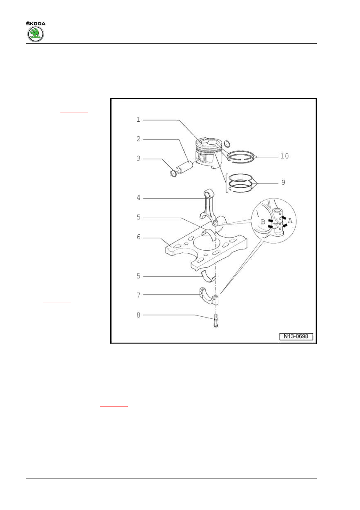
Fabia II 2007 ➤ , Fabia II 2009 ➤ , Fabia II 2011 ➤ , Rapid India 2011 ...
1.6/77 kW MPI engine - Edition 03.2014
3 Pistons and conrods
3.1 Piston and conrod - Summary of components
1 - Piston
❑ check ⇒ page 50
❑ mark installation posi‐
tion and matching cylin‐
der
❑ arrow on the piston
crown faces towards the
belt pulley side
❑ Piston dimension
(based on cylinder hon‐
ing class): ∅ 76.46 mm
or 76.48 mm ⇒ ETKA Electronic Catalogue of
Original Parts
2 - Piston pin
❑ if stiff, heat piston to 60°
C
❑ use drift - T10046- for
removing and installing
❑ Assignment ⇒ ETKA -
Electronic Catalogue of
Original Parts
3 - Circlip
4 - Conrod
❑ always replace as a set
only
❑ separate new conrod
⇒ page 50
❑ mark matching cylinder
-A-
❑ Fitting position: Mark‐
ings -B- point towards
belt pulley side
❑ located axially by pis‐
tons
❑ Assignment ⇒ ETKA - Electronic Catalogue of Original Parts
5 - Bearing shell
❑ pay attention to correct installation position ⇒ page 49
❑ do not mix up used bearing shells (mark)
6 - Cylinder block
❑ inspect cylinder bore ⇒ page 50
❑ Cylinder dimension (according to honing class): ∅ 76.51 mm or 76.53 mm
7 - Conrod bearing cap
❑ as a result of the conrods separated in the cracking process, the cover fits only in one position and only
to the relevant conrod
8 - Conrod bolt, 30 Nm + torque a further + 90° (1/4 turn)
❑ replace
❑ Oil thread and contact surfaces
48 Rep. gr.13 - Crankshaft group
Page 55

Fabia II 2007 ➤ , Fabia II 2009 ➤ , Fabia II 2011 ➤ , Rapid India 2011 ...
1.6/77 kW MPI engine - Edition 03.2014
9 - Oil scraper ring
❑ carefully remove and install 3-part oil scraper rings by hand
❑ Inspect gap clearance ⇒ page 49
❑ End clearance cannot be measured
10 - Compression rings
❑ Offset joint 120°
❑ use piston ring pliers for removing and installing
❑ marking -TOP- must face towards piston crown
❑ Inspect gap clearance ⇒ page 49
❑ Inspect end clearance ⇒ page 49
Bearing shell installation position
Bearing shell -1- with oil drilling -arrow- for conrod.
Bearing shell -2- without oil drilling for conrod bearing cap.
– Insert bearing shells in the conrod and in the conrod bearing
cap centred.
The dimension -a- must be the same on the right and left.
3.2 Inspect piston, piston rings and cylinder
bore
Inspecting piston ring gap clearance
– Push in ring at right angles to the cylinder wall from the top
through to the bottom cylinder opening, about 15 mm from the
lower cylinder edge.
Piston ring
dimensions in mm
1. Compression ring 0.20 … 0.50 1.0
2. Compression ring 0.40 … 0.60 1.0
Oil scraper ring 0.20 … 1.10
1)
no specification possible for wear limit
Inspect piston ring end clearance
– Clean annular grooves of piston before measurement is taken.
Piston ring
dimensions in mm
1. Compression ring 0.04 … 0.08 0.15
2. Compression ring 0.02 … 0.08 0.15
Oil scraper ring cannot be measured
new Wear
new Wear
limit
1)
-
limit
3. Pistons and conrods 49
Page 56
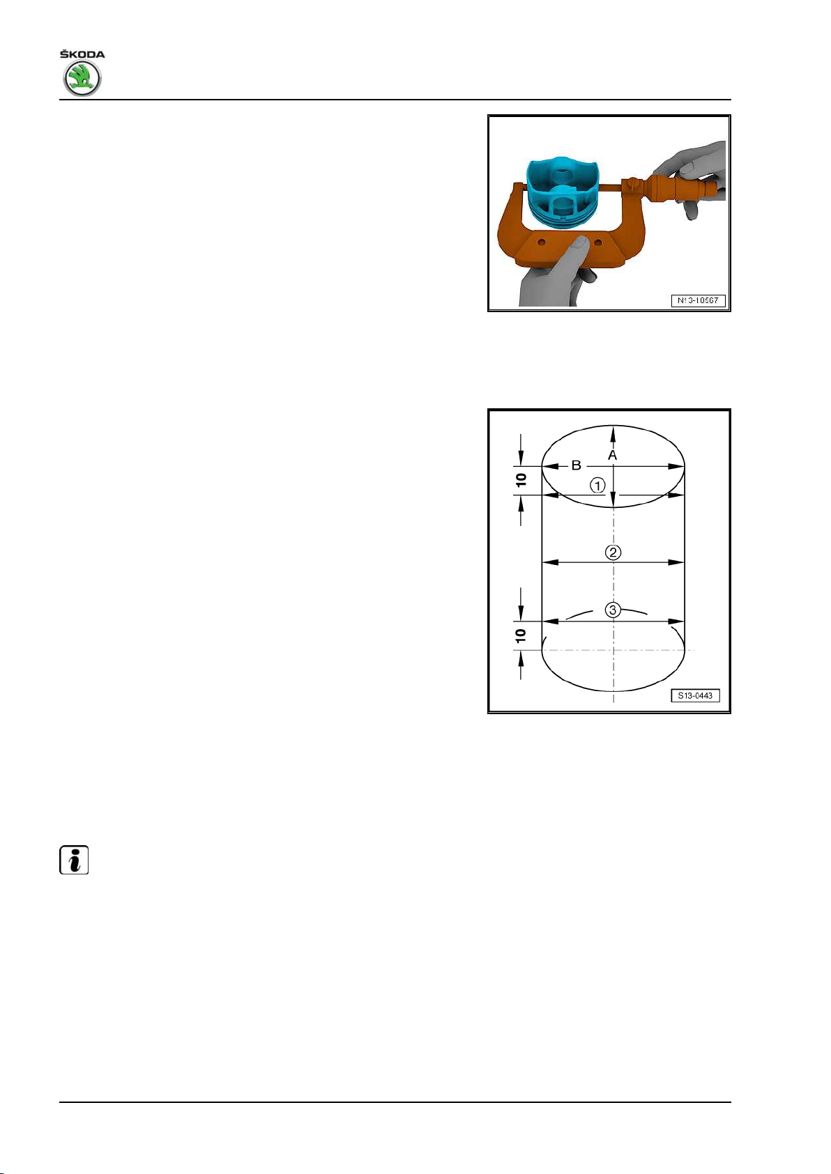
Fabia II 2007 ➤ , Fabia II 2009 ➤ , Fabia II 2011 ➤ , Rapid India 2011 ...
1.6/77 kW MPI engine - Edition 03.2014
Inspecting pistons
Special tools and workshop equipment required
♦ External micrometer 75...100 mm
– Measure about 10 mm from the lower edge, offset at right an‐
gles to the piston pin shaft.
♦ Variation compared to nominal diameter: 0.04 mm
Inspecting cylinder bore
Special tools and workshop equipment required
♦ Internal precision measuring instrument 50...100 mm
– Measure at three points crosswise in a transverse direction
-A- and lengthwise -B-.
♦ Deviations from specified dimension: 0.08 mm
Note
Do not measure the cylinder bore if the cylinder block is fixed to
the assembly stand -MP9-101- with the engine mount -MP1-202- ,
as this may result in incorrect measurements.
3.3 Separating new conrod
It can happen that on new conrods, the provided separation point
is not completely cracked. If the conrod bearing cap cannot be
removed by hand, then proceed as follows:
– Mark the assignment of the conrod to the cylinder.
50 Rep. gr.13 - Crankshaft group
Page 57
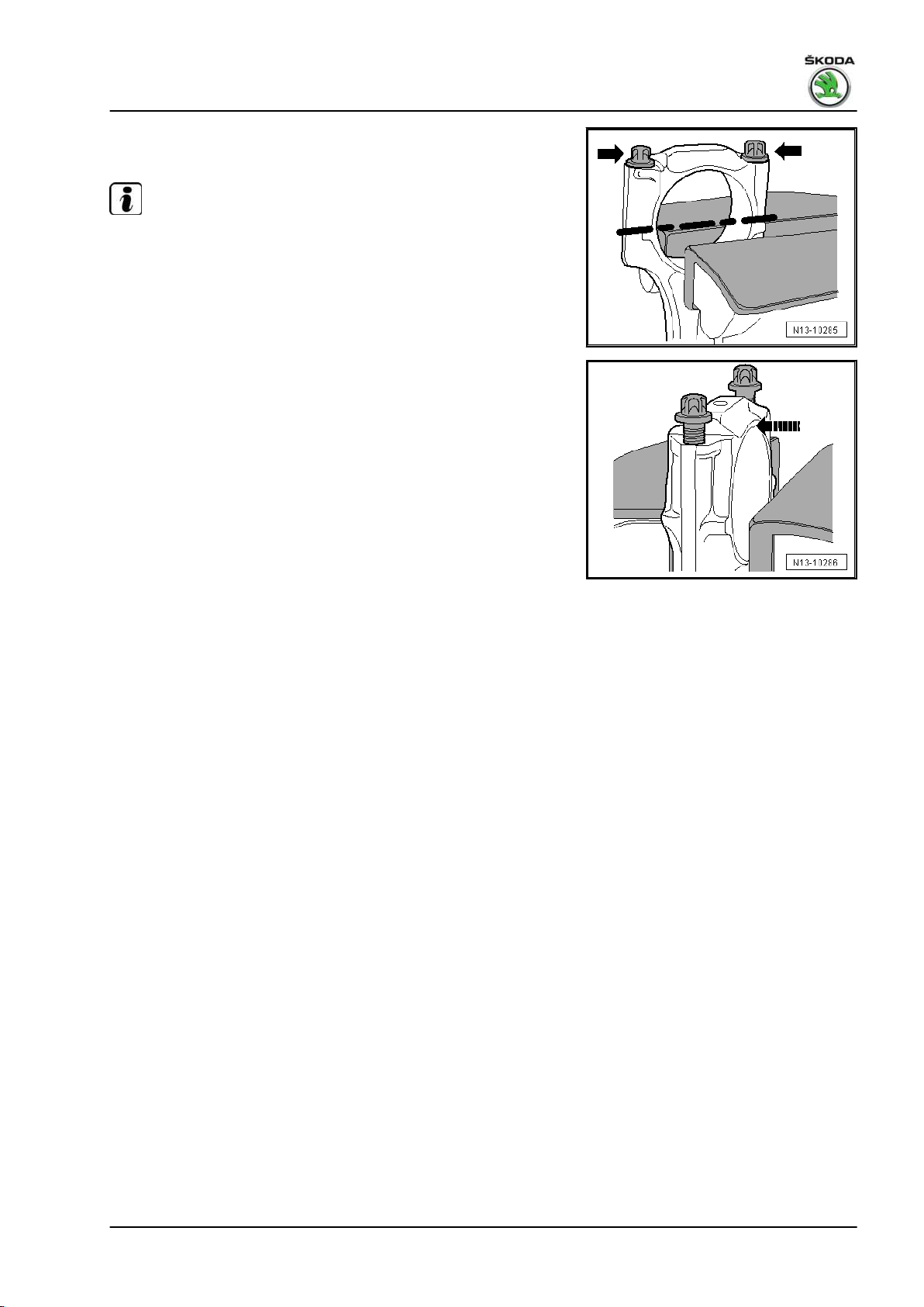
Fabia II 2007 ➤ , Fabia II 2009 ➤ , Fabia II 2011 ➤ , Rapid India 2011 ...
1.6/77 kW MPI engine - Edition 03.2014
– Slightly tension the conrod, as shown in the illustration, in a
vice provided with aluminium protective jaws.
Note
♦
Only tension the conrod slightly in order to avoid damage.
♦
The conrod is clamped below the broken line.
– Unscrew both screws -arrows- by approx. 5 turns.
– Carefully knock against the conrod bearing cap with a plastic
hammer in -direction of arrow- in order to loosen it.
3. Pistons and conrods 51
Page 58

Fabia II 2007 ➤ , Fabia II 2009 ➤ , Fabia II 2011 ➤ , Rapid India 2011 ...
1.6/77 kW MPI engine - Edition 03.2014
15 – Cylinder head, valve gear
1 Cylinder head
1.1 Distinguishing features of cylinder
heads
Version A
♦ The caps for the camshafts are screwed on with 2 screws.
♦ The hall sender - G40- is installed behind the 4th cylinder.
♦ Use the camshaft fixer/locator - T10171A- to check and set the
timing.
Version B
♦ The caps for the camshafts are screwed on with 1 screw.
♦ The hall sender - G40- is installed behind the 2nd cylinder.
♦ Use two fixing bolts - T10414- to check and set the timing.
1.2 Cylinder head - Summary of compo‐
nents (version A)
For engine with identification characters BTS, CFNA, CLSA
Testing compression pressure ⇒ page 85 .
Note
♦
When installing a replacement cylinder head, all the contact surfaces between the supporting elements,
roller rocker arms and the cam tracks must be oiled before installing the camshaft housing.
♦
Do not remove the plastic bases supplied as a protection for the open valves until just before fitting on the
cylinder head.
♦
If the cylinder head is replaced, also the entire coolant must be replaced.
♦
Disassembling and assembling intake manifold ⇒ page 159 .
52 Rep. gr.15 - Cylinder head, valve gear
Page 59
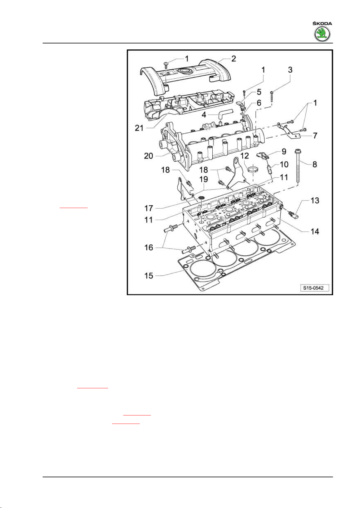
Fabia II 2007 ➤ , Fabia II 2009 ➤ , Fabia II 2011 ➤ , Rapid India 2011 ...
1 - 10 Nm
2 - Cover for camshaft housing
3 - 10 Nm + torque a further 90°
(1/4 turn)
❑ replace
❑ tighten from inside to
outside
4 - to air filter housing
5 - Hall sender - G406 - O-ring
❑ replace if damaged
7 - Support
8 - Cylinder head bolt
❑ replace
❑ observe the mounting
instructions and se‐
quence for loosening
and tightening
⇒ page 83
9 - Roller rocker arm
❑ inspect roller bearings
of roller for smooth op‐
eration
❑ oil contact surfaces
❑ to install, clip onto the
supporting element and
secure with locking clip
10 - Supporting element
❑ do not interchange
❑ with hydraulic valve
clearance compensa‐
tion
❑ oil contact surfaces
11 - Dowel pins
12 - Sealing ring
❑ replace
❑ 4 pieces
❑ inserted into the cylinder head
13 - Oil pressure switch - F1- , 25 Nm
❑ 0.05 MPa (0.5 bar)
❑ check ⇒ page 109
❑ Cut open gasket ring if leaking and replace
1.6/77 kW MPI engine - Edition 03.2014
14 - Cylinder head
❑ removing and installing ⇒ page 83
❑ check for distortion ⇒ page 54
❑ Sealing surface to the camshaft housing must be free of oil and grease.
❑ after replacing fill entire system with fresh coolant
15 - Cylinder head gasket
❑ replace
❑ metal gasket
1. Cylinder head 53
Page 60

Fabia II 2007 ➤ , Fabia II 2009 ➤ , Fabia II 2011 ➤ , Rapid India 2011 ...
1.6/77 kW MPI engine - Edition 03.2014
16 - Guide bolt
❑ Tightening torque: 20 Nm
17 - Oil filter
❑ inserted into cylinder head
❑ replace
18 - 20 Nm
19 - Lifting eyes
20 - Camshaft housing
❑ removing and installing ⇒ page 79
❑ Sealing surface to the cylinder head must be free of oil and grease.
21 - Cable guide
❑ Screwed onto camshaft housing to 8 Nm
Inspecting the cylinder head for distortion
Maximum permissible deviation: 0.05 mm
1.3 Cylinder head - Summary of compo‐
nents (version B)
For engine with identification characters CFNA
54 Rep. gr.15 - Cylinder head, valve gear
Page 61
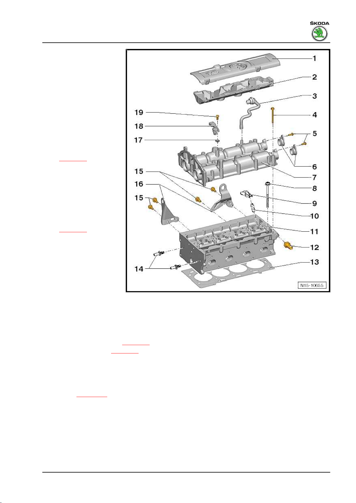
Fabia II 2007 ➤ , Fabia II 2009 ➤ , Fabia II 2011 ➤ , Rapid India 2011 ...
1.6/77 kW MPI engine - Edition 03.2014
1 - Cover for camshaft housing
2 - Cable guide
3 - to air filter housing
4 - 10 Nm + torque a further 90°
(1/4 turn)
❑ replace
❑ tighten from inside to
outside
5 - 10 Nm
6 - Caps for camshafts
7 - Camshaft housing
❑ removing and installing
⇒ page 79
❑ Sealing surface to the
cylinder head must be
free of oil and grease.
8 - Cylinder head bolt
❑ replace
❑ observe the mounting
instructions and se‐
quence for loosening
and tightening
⇒ page 83
9 - Roller rocker arm
❑ inspect roller bearings
of roller for smooth op‐
eration
❑ oil contact surfaces
❑ to install, clip onto the
supporting element and
secure with locking clip
10 - Supporting element
❑ do not interchange
❑ with hydraulic valve clearance compensation
❑ oil contact surfaces
11 - Cylinder head
❑ removing and installing ⇒ page 83
❑ check for distortion ⇒ page 56
❑ Sealing surface to the camshaft housing must be free of oil and grease.
❑ after replacing fill entire system with fresh coolant
12 - Oil pressure switch - F1- , 25 Nm
❑ 0.05 MPa (0.5 bar)
❑ check ⇒ page 109
❑ Cut open gasket ring if leaking and replace
13 - Cylinder head gasket
❑ replace
❑ metal gasket
14 - Guide bolt
❑ Tightening torque: 20 Nm
1. Cylinder head 55
Page 62

Fabia II 2007 ➤ , Fabia II 2009 ➤ , Fabia II 2011 ➤ , Rapid India 2011 ...
1.6/77 kW MPI engine - Edition 03.2014
15 - 20 Nm
16 - Lifting eyes
17 - O-ring
❑ replace if damaged
18 - Hall sender - G4019 - 10 Nm
Inspecting the cylinder head for distortion
Maximum permissible deviation: 0.05 mm
1.4 Check the timing for the cylinder head
version A
For engine with identification characters BTS, CFNA, CLSA
Special tools and workshop equipment required
♦ Adapter for dial gauge - T10170♦ Camshaft fixer/locator - T10171A♦ Dial gauge
Test sequence
– Remove cover for camshaft housing and air filter housing
⇒ page 161 .
– Remove cap for camshafts.
– Remove ignition coil from cylinder 1 ⇒ page 184 and release
the spark plug.
– Screw adapter for dial gauge - T10170- up to the stop into the
spark plug thread.
– Insert the dial gauge -A- with extension - T10170/1- up to the
stop and fix in place using the clamping screw -arrow-.
– Rotate the crankshaft in direction of rotation of engine on TDC
for cylinder 1. Note down the position of the small pointer of
the dial gauge.
56 Rep. gr.15 - Cylinder head, valve gear
Page 63

Fabia II 2007 ➤ , Fabia II 2009 ➤ , Fabia II 2011 ➤ , Rapid India 2011 ...
1.6/77 kW MPI engine - Edition 03.2014
The holes -arrows- in the camshafts must be positioned as
shown. If necessary rotate the crankshaft a further revolution
(360°).
Note
♦
If the crankshaft was turned more than 0.01 mm past the top
dead centre, the crankshaft must once again be turned approx
45° in the opposite direction of rotation of the engine. Then
position the crankshaft in direction of rotation of engine on top
dead centre of cylinder 1.
♦
Permissible deviation from TDC for cylinder 1: ± 0.01 mm.
– Insert camshaft fixer/locator - T10171A- up to the stop into the
holes in the camshaft housing.
• The locking bolts -arrows 1- must engage in the holes
-arrows 2-. The inscription “TOP” -arrow 3- must be at the top.
If the camshaft fixer/locator - T10171A- is not insertable up to the
stop in the camshaft openings, the timing is not correct and must
be set again ⇒ page 59 .
The timing is O.K., if the camshaft fixer/locator - T10171A- can be
inserted up to the stop into the camshaft openings.
The further assembly is carried out in reverse order to disassem‐
bly. However, pay attention to the following:
♦ Replace the gasket rings for the caps of the camshafts and oil
before assembly.
1.5 Check the timing for the cylinder head version B
For engine with identification characters CFNA
Special tools and workshop equipment required
♦ Adapter for dial gauge - T10170♦ Fixing bolt - T10414- , 2 pieces
♦ Dial gauge
Test sequence
– Remove cover for camshaft housing and air filter housing
⇒ page 161 .
– Remove ignition coil from cylinder 1 ⇒ page 184 and release
the spark plug.
– Screw adapter for dial gauge - T10170- up to the stop into the
spark plug thread.
– Insert the dial gauge -A- with extension - T10170/1- up to the
stop and fix in place using the clamping screw -arrow-.
– Rotate the crankshaft in direction of rotation of engine on TDC
for cylinder 1. Note down the position of the small pointer of
the dial gauge.
1. Cylinder head 57
Page 64

Fabia II 2007 ➤ , Fabia II 2009 ➤ , Fabia II 2011 ➤ , Rapid India 2011 ...
1.6/77 kW MPI engine - Edition 03.2014
– Remove caps -arrows- for camshafts.
The holes -arrows- in the camshafts must be positioned as
shown, if necessary rotate the crankshaft a further revolution
(360°).
Note
♦
If the crankshaft is turned more than 0.01 mm past the top
dead centre, the crankshaft must once again be turned approx
45° in the opposite direction of rotation of the engine. Then
position the piston for cylinder 1 on top dead centre by turning
in direction of rotation of engine.
♦
Permissible deviation for setting the piston for cylinder 1 on
top dead centre: ± 0.01 mm
– Insert the fixing bolt - T10414- up to the stop into the camshaft
openings.
The interlocking lugs -arrow 1- must engage in the holes
-arrow 2- of the camshafts.
If the fixing bolt - T10414- is not insertable up to the stop in the
camshaft openings, the timing is not correct and must be set again
⇒ page 63 .
• The timing is O.K., if the fixing bolts - T10414- slide fully into
the camshaft openings and can be secured with the fixing
screws -arrows- for the caps of the camshafts.
The further assembly is carried out in reverse order to disassem‐
bly. However, pay attention to the following:
♦ Replace the gasket rings for the caps of the camshafts and oil
before assembly.
58 Rep. gr.15 - Cylinder head, valve gear
Page 65
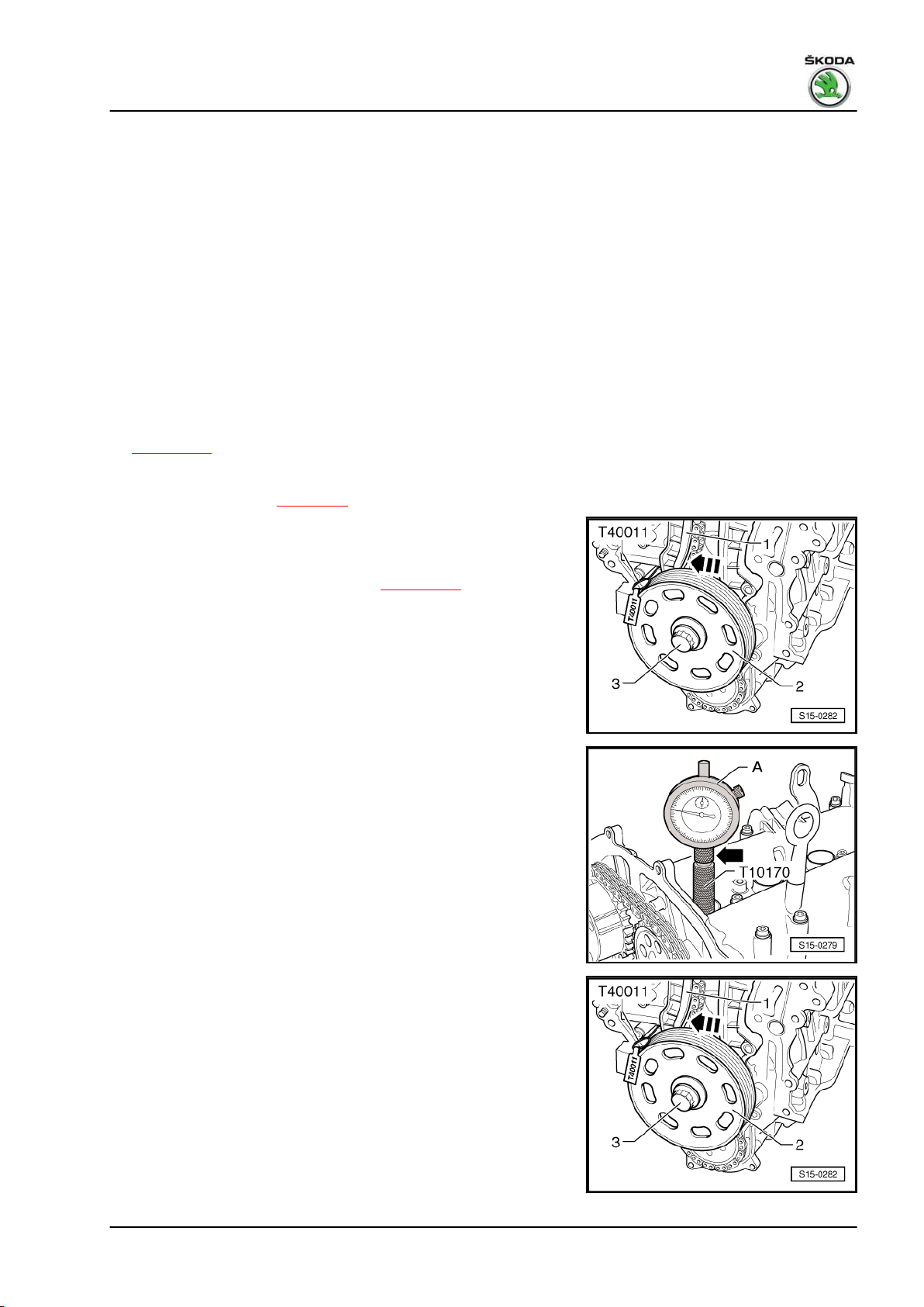
Fabia II 2007 ➤ , Fabia II 2009 ➤ , Fabia II 2011 ➤ , Rapid India 2011 ...
1.6/77 kW MPI engine - Edition 03.2014
1.6 Setting the timing for the cylinder head version A
For engine with identification characters BTS, CFNA, CLSA
Special tools and workshop equipment required
♦ Adapter for dial gauge - T10170♦ Camshaft fixer/locator - T10171A♦ Counterholder - T10172♦ Counterholder - T30004 (3415)♦ Rig pin - T40011♦ Dial gauge
Work procedure
– Remove cover for camshaft housing and air filter housing
⇒ page 161 .
– Remove cap for camshafts.
– Remove timing case ⇒ page 26 .
– Insert the spacer sleeve, the crankshaft belt pulley -2- and the
fixing screw -3- in order to turn the crankshaft. Tighten the
crankshaft screw (to do so, use the counterholder - T30004- ).
– Remove ignition coil from cylinder 1 ⇒ page 184 and release
the spark plug.
– Screw adapter for dial gauge - T10170- up to the stop into the
spark plug thread.
– Insert the dial gauge -A- with extension - T10170/1- up to the
stop and fix in place using the clamping screw -arrow-.
– Rotate the crankshaft in direction of rotation of engine on TDC
for cylinder 1. Note down the position of the small pointer of
the dial gauge.
– Turn crankshaft 45° in the opposite direction of rotation of the
engine.
– Press the tensioning rail -1- in -direction of arrow- and interlock
the piston with the rig pin - T40011- .
1. Cylinder head 59
Page 66

Fabia II 2007 ➤ , Fabia II 2009 ➤ , Fabia II 2011 ➤ , Rapid India 2011 ...
1.6/77 kW MPI engine - Edition 03.2014
– Mark with a suitable felt-tip pen the direction of rotation of the
timing chain -3-.
For engine with identification characters BTS
Note
The fixing screw of the camshaft adjuster -2- has a left-hand
thread.
– Release screws -2- and -4- and remove the camshaft adjuster
-1- with the timing chain -3-. Use counterholder - T10172- to
counterhold.
– Mount again camshaft adjuster -1-.
– Replace screws -2- and -4- and tighten the screw -2- to 40 Nm
and the screw -4- to 50 Nm. Use counterholder - T10172- to
counterhold.
For engine with identification characters CFNA, CLSA
– Release screws -2- and remove chain sprocket of inlet cam‐
shaft -1- with timing chain -3-. Use counterholder - T10172- for
this purpose.
– Re-insert the chain sprocket of the inlet camshaft -1-.
– Replace the screws -2- and tighten to 50 Nm. Use counter‐
holder - T10172- to counterhold.
Continued for all engines
– Turn the inlet and exhaust camshaft until the camshaft fixer/
locator - T10171A- can be inserted up to the stop into the
camshaft openings.
• The locking bolts -arrows 1- must engage in the holes
-arrows 2-. The inscription “TOP” -arrow 3- must be at the top.
Note
When turning, the camshafts must not be moved axially.
60 Rep. gr.15 - Cylinder head, valve gear
Page 67
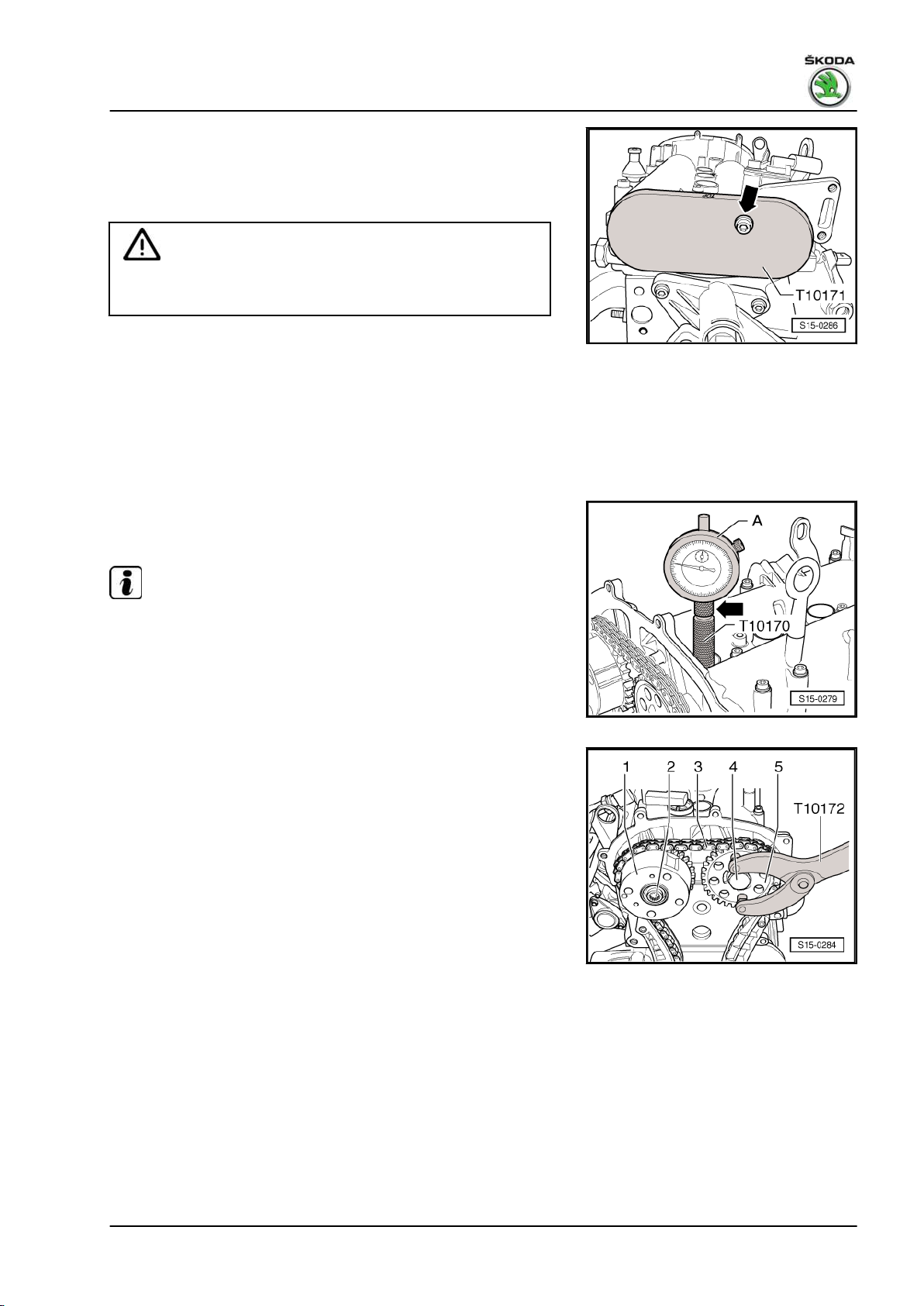
Fabia II 2007 ➤ , Fabia II 2009 ➤ , Fabia II 2011 ➤ , Rapid India 2011 ...
1.6/77 kW MPI engine - Edition 03.2014
– To secure the camshaft fixer/locator - T10171A- screw in a M6
screw -arrow- by hand; do not tighten.
– Slacken screws of the camshaft sprockets.
Absolutely use counterholder - T10172- .
Caution
Do not use the camshaft fixer/locator - T10171A- as a coun‐
terholder.
– Removing the camshaft chain sprocket.
– Place the timing chain onto the camshaft chain sprockets in
compliance with the running direction and reinsert the re‐
moved camshaft chain sprocket.
– Screw in the camshaft screws so far so that the camshaft chain
sprockets can be turned.
– Tighten the timing chain, by pulling out the rig pin - T40011- .
– Rotate crankshaft to TDC for cylinder 1.
Permissible deviation from TDC for cylinder 1: ± 0.01 mm.
Note
If the crankshaft was turned more than 0.01 mm past the top dead
centre, the crankshaft must once again be turned approx 45° in
the opposite direction of rotation of the engine. Then position the
crankshaft in direction of rotation of engine on top dead centre of
cylinder 1.
For engine with identification characters BTS
– Hold the camshaft chain sprockets -1- and -5- in this position
with the counterholder - T10172- and tighten the screw -2(left-hand thread) to 40 Nm and the screw -4- to 50 Nm.
For engine with identification characters CFNA, CLSA
1. Cylinder head 61
Page 68
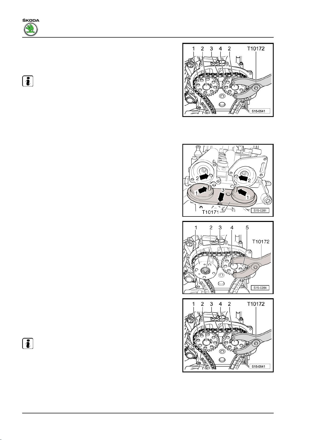
Fabia II 2007 ➤ , Fabia II 2009 ➤ , Fabia II 2011 ➤ , Rapid India 2011 ...
1.6/77 kW MPI engine - Edition 03.2014
– Hold the camshaft chain sprockets -1- and -4- in this position
with the counterholder - T10172- and tighten screws -2- to
50 Nm.
Continued for all engines
Note
When tightening the camshaft screws, the crankshaft must not
turn and the timing chain -3- must remain tightened.
– Remove the camshaft fixer/locator - T10171A- .
– Turn the crankshaft in direction of rotation of engine by 2 turns
on TDC for cylinder 1.
Permissible deviation from TDC for cylinder 1: ± 0.01 mm.
– Insert camshaft fixer/locator - T10171A- up to the stop into the
holes in the camshaft housing.
If the camshaft fixer/locator - T10171A- is not insertable.
– Repeat setting.
If the camshaft fixer/locator - T10171A- is insertable.
For engine with identification characters BTS
– Remove the camshaft fixer/locator - T10171A- , hold the cam‐
shaft chain sprockets with the counterholder - T10172- and
torque the screws -2- (left-hand thread) and -4- a further 90°
1
/4 turn with a rigid wrench.
For engine with identification characters CFNA, CLSA
– Remove the camshaft fixer/locator - T10171A- , hold the cam‐
shaft chain sprockets with the counterholder - T10172- and
torque the screws -2- a further 1/4 turn (90°) with a rigid
wrench.
Continued for all engines
Note
♦
On engine with identification characters BTS, the fixing screw
of the camshaft adjuster -2- has a left-hand thread.
♦
The camshaft chain sprockets must not turn when tightening.
– Turn again the crankshaft in direction of rotation of engine by
2 turns on TDC for cylinder 1.
Permissible deviation from TDC for cylinder 1: ± 0.01 mm.
62 Rep. gr.15 - Cylinder head, valve gear
Page 69
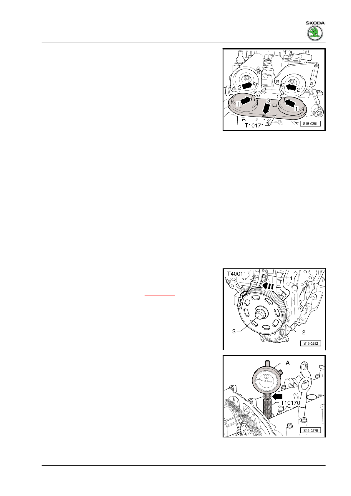
Fabia II 2007 ➤ , Fabia II 2009 ➤ , Fabia II 2011 ➤ , Rapid India 2011 ...
1.6/77 kW MPI engine - Edition 03.2014
– Insert camshaft fixer/locator - T10171A- up to the stop into the
holes in the camshaft housing.
If the camshaft fixer/locator - T10171A- is not insertable.
– Repeat setting.
The further assembly is carried out in reverse order to disassem‐
bly. However, pay attention to the following:
♦ Before installing, undo the holding down bolts, remove the
crankshaft-belt pulley and spacer sleeve.
♦ Install timing case ⇒ page 26 .
♦ Replace the gasket rings for the caps of the camshafts and oil
before assembly.
1.7 Setting the timing for the cylinder head
version B
For engine with identification characters CFNA
Special tools and workshop equipment required
♦ Adapter for dial gauge - T10170♦ Fixing bolt - T10414- , 2 pieces
♦ Counterholder - T10172♦ Counterholder - T30004 (3415)♦ Rig pin - T40011♦ Dial gauge
Work procedure
– Remove timing case ⇒ page 26 .
– Insert the spacer sleeve, the crankshaft belt pulley -2- and the
fixing screw -3- in order to turn the crankshaft. Tighten the
crankshaft screw (to do so, use the counterholder - T30004- ).
– Remove ignition coil from cylinder 1 ⇒ page 184 and release
the spark plug.
– Screw adapter for dial gauge - T10170- up to the stop into the
spark plug thread.
– Insert the dial gauge -A- with extension - T10170/1- up to the
stop and fix in place using the clamping screw -arrow-.
– Rotate the crankshaft in direction of rotation of engine on TDC
for cylinder 1. Note down the position of the small pointer of
the dial gauge.
– Turn crankshaft 45° in the opposite direction of rotation of the
engine.
1. Cylinder head 63
Page 70
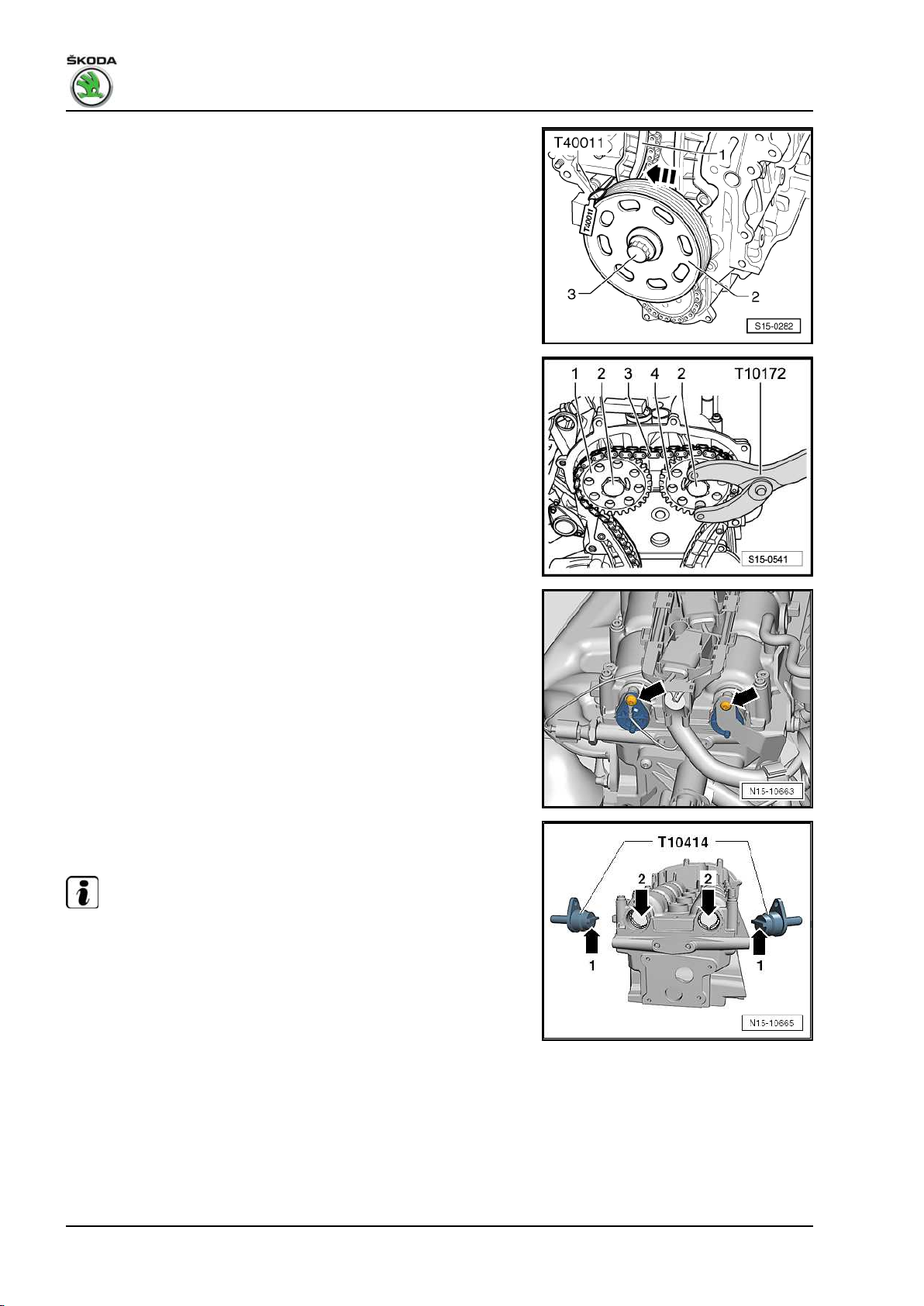
Fabia II 2007 ➤ , Fabia II 2009 ➤ , Fabia II 2011 ➤ , Rapid India 2011 ...
1.6/77 kW MPI engine - Edition 03.2014
– Press the tensioning rail -1- in -direction of arrow- and interlock
the piston with the rig pin - T40011- .
– Mark with a suitable felt-tip pen the direction of rotation of the
timing chain -3-.
– Release screws -2- and remove the camshaft chain sprockets
-1- and -4- with the timing chain -3-. Use counterholder -
T10172- to counterhold.
– Re-insert camshaft chain sprockets -1- and -4-.
– Replace the screws -2- and tighten to 50 Nm. Use counter‐
holder - T10172- to counterhold.
– Remove caps -arrows- for camshafts.
– Turn the camshafts until the fixing bolts - T10414- slide into
the inlet and outlet camshafts up to the stop.
The interlocking lugs -arrow 1- must engage in the holes
-arrow 2- of the camshafts.
Note
When turning, the camshafts must not be moved axially.
64 Rep. gr.15 - Cylinder head, valve gear
Page 71
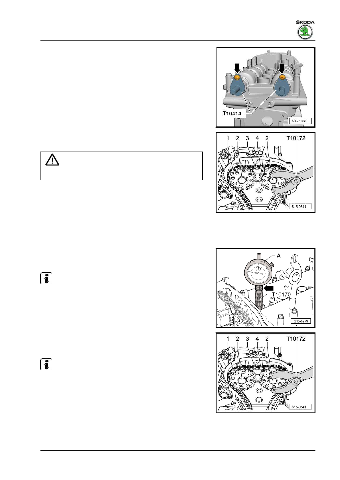
Fabia II 2007 ➤ , Fabia II 2009 ➤ , Fabia II 2011 ➤ , Rapid India 2011 ...
1.6/77 kW MPI engine - Edition 03.2014
– To secure the fixing bolts - T10414- , screw in the fixing screws
-arrows- for the caps of the camshafts by hand, do not tighten
forcefully.
– Release screws -2- of camshaft chain sprockets.
Absolutely use counterholder - T10172- .
Caution
Do not use the fixing bolts - T10414- as a counterholder.
– Remove a camshaft chain sprocket.
– Place the timing chain onto the camshaft chain sprockets in
compliance with the running direction and reinsert the re‐
moved camshaft chain sprocket.
– Screw in the camshaft screws so far so that the camshaft chain
sprockets can be turned.
– Tighten the timing chain, by pulling out the rig pin - T40011- .
– Rotate crankshaft to TDC for cylinder 1.
Permissible deviation from TDC for cylinder 1: ± 0.01 mm
Note
If the crankshaft was turned more than 0.01 mm past the top dead
centre, the crankshaft must once again be turned approx 45° in
the opposite direction of rotation of the engine. Then position the
crankshaft in direction of rotation of engine on top dead centre of
cylinder 1.
– Hold the camshaft chain sprockets -1- and -4- in this position
with the counterholder - T10172- and tighten screws -2- to
50 Nm.
Note
When tightening the camshaft screws, the crankshaft must not
turn and the timing chain -3- must remain tightened.
– Remove the two locking bolts - T10414- .
– Once again turn the crankshaft by 2 turns in the direction of
rotation of the engine on TDC for cylinder 1.
Permissible deviation from TDC for cylinder 1: ± 0.01 mm
– Insert the two fixing bolts - T10414- again into the camshafts
up to the stop.
1. Cylinder head 65
Page 72
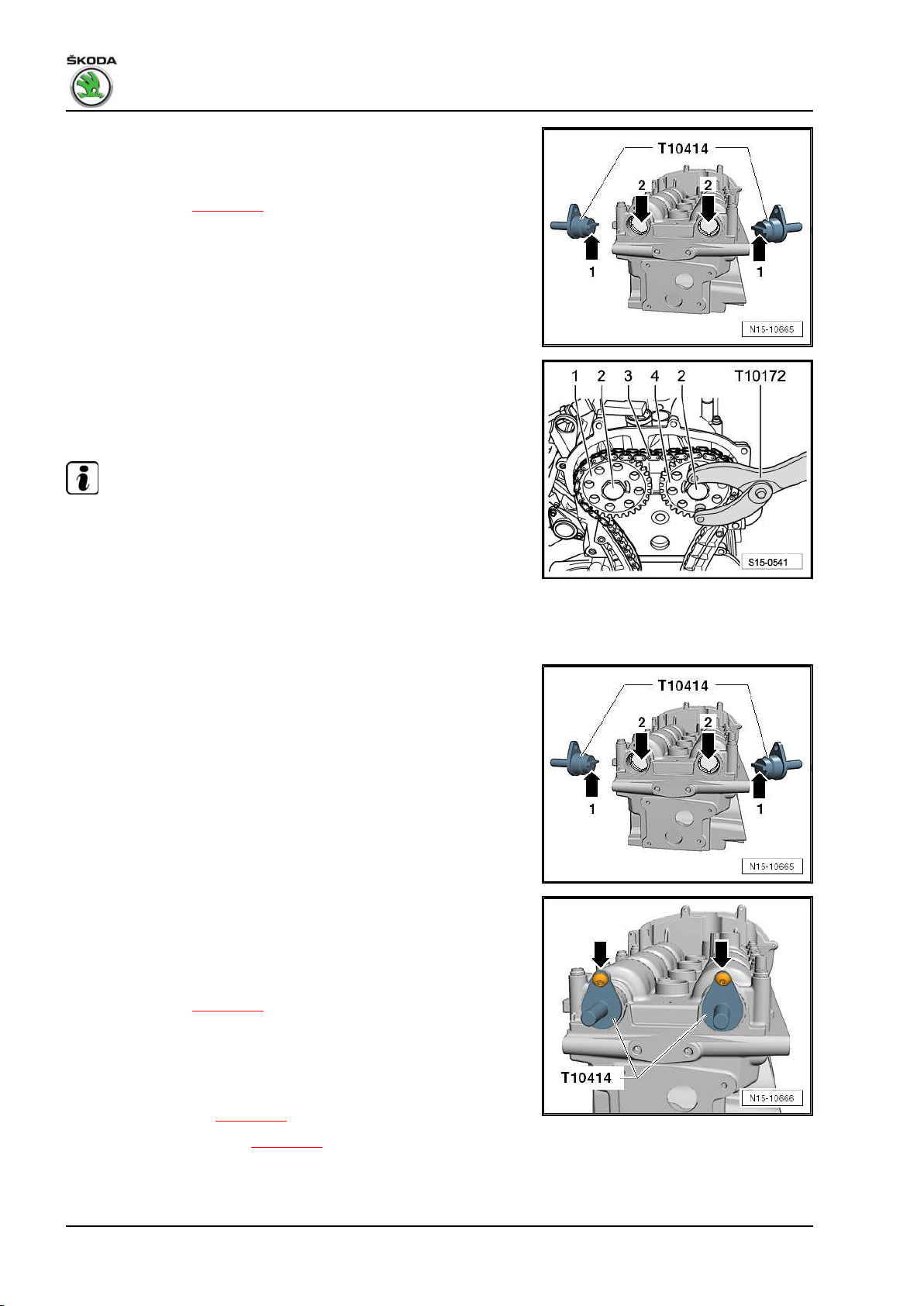
Fabia II 2007 ➤ , Fabia II 2009 ➤ , Fabia II 2011 ➤ , Rapid India 2011 ...
1.6/77 kW MPI engine - Edition 03.2014
The interlocking lugs -arrow 1- must engage in the holes
-arrow 2- of the camshafts.
If the fixing bolts - T10414- are not insertable:
– Repeat setting ⇒ page 63 .
If the fixing bolts - T10414- are insertable:
– Remove both fixing bolts - T10414- , hold the camshaft chain
sprockets with the counterholder - T10172- and torque the
screws -2- a further 90° (1/4 turn) with a rigid wrench.
Continued for all engines
Note
The camshaft chain sprockets must not turn when tightening.
– Once again turn the crankshaft by 2 turns in the direction of
rotation of the engine on TDC for cylinder 1.
Permissible deviation from TDC for cylinder 1: ± 0.01 mm
– Insert the two fixing bolts - T10414- again into the camshafts
up to the stop.
The interlocking lugs -arrow 1- must engage in the holes
-arrow 2- of the camshafts.
• The timing is O.K., if the fixing bolts - T10414- slide fully into
the camshaft openings and can be secured with the fixing
screws -arrows- for the caps of the camshafts.
If the fixing bolts - T10414- cannot be inserted into the camshaft
holes up to the stop, the timing is incorrect:
– Repeat setting ⇒ page 63 .
The further assembly is carried out in reverse order to disassem‐
bly. However, pay attention to the following:
♦ Before installing, undo the holding down bolts, remove the
crankshaft-belt pulley and spacer sleeve.
♦ Install timing case ⇒ page 26 .
♦ Install the V-ribbed belt ⇒ page 18 .
♦ Replace the gasket rings for the caps of the camshafts and oil
before assembly.
66 Rep. gr.15 - Cylinder head, valve gear
Page 73

Fabia II 2007 ➤ , Fabia II 2009 ➤ , Fabia II 2011 ➤ , Rapid India 2011 ...
1.6/77 kW MPI engine - Edition 03.2014
1.8 Removing and installing timing chain and drive chain for cylinder head version A
For engine with identification characters BTS, CFNA, CLSA
Special tools and workshop equipment required
♦ Counterholder - T30004 (3415)♦ Extractor - T10094A♦ Adapter for dial gauge - T10170♦ Camshaft fixer/locator - T10171A♦ Counterholder - T10172♦ Rig pin - T40011♦ Dial gauge
Removing
– Unscrew cap for camshafts.
– Remove ignition coil from cylinder 1 ⇒ page 184 and release
the spark plug.
– Screw adapter for dial gauge - T10170- up to the stop into the
spark plug thread.
– Insert the dial gauge -A- with extension - T10170/1- up to the
stop and fix in place using the clamping screw -arrow-.
– Rotate the crankshaft in direction of rotation of engine on TDC
for cylinder 1. Note down the position of the small pointer of
the dial gauge.
The holes -arrows- in the camshafts must be positioned as
shown. If necessary rotate the crankshaft a further revolution
(360°).
Note
♦
If the crankshaft was turned more than 0.01 mm past the top
dead centre, the crankshaft must once again be turned approx
45° in the opposite direction of rotation of the engine. Then
position the crankshaft in direction of rotation of engine on top
dead centre of cylinder 1.
♦
Permissible deviation from TDC for cylinder 1: ± 0.01 mm.
1. Cylinder head 67
Page 74

Fabia II 2007 ➤ , Fabia II 2009 ➤ , Fabia II 2011 ➤ , Rapid India 2011 ...
1.6/77 kW MPI engine - Edition 03.2014
– Insert camshaft fixer/locator - T10171A- up to the stop into the
holes in the camshaft housing.
• The locking bolts -arrows 1- must engage in the holes
-arrows 2-. The inscription “TOP” -arrow 3- must be at the top.
– To secure the camshaft fixer/locator - T10171A- screw in a M6
screw -arrow- by hand; do not tighten.
– Remove timing case ⇒ page 26 .
– Pull off cover -1- from chain sprocket of oil pump.
– Press the tensioning rail by hand in the
-direction of the arrow- and interlock the piston with the rig pin
- T40011- .
– Remove chain tensioner -2-.
68 Rep. gr.15 - Cylinder head, valve gear
Page 75
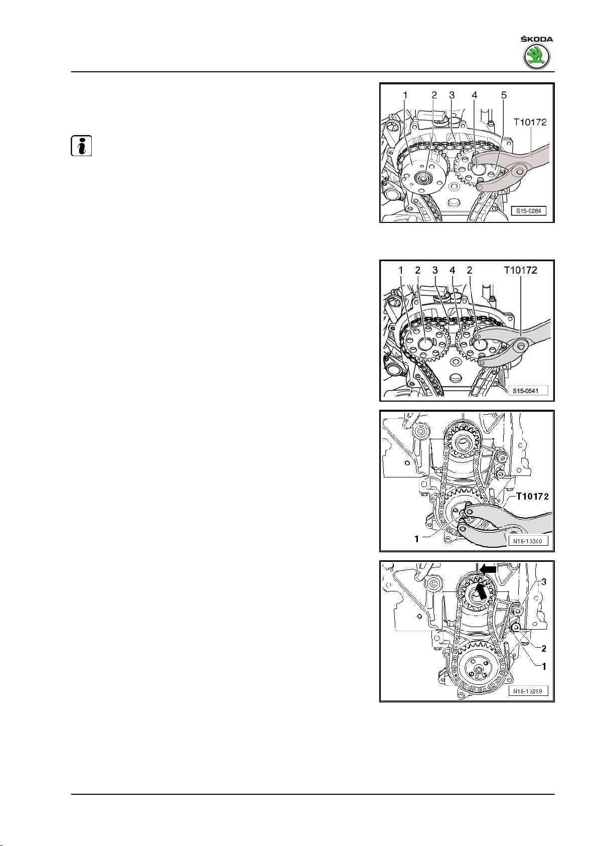
Fabia II 2007 ➤ , Fabia II 2009 ➤ , Fabia II 2011 ➤ , Rapid India 2011 ...
1.6/77 kW MPI engine - Edition 03.2014
– Mark with a suitable felt-tip pen the direction of rotation of the
timing chain -3-.
For engine with identification characters BTS
Note
The fixing screw of the camshaft adjuster -2- has a left-hand
thread.
– Release screws -2- and -4- and remove the camshaft adjuster
-1- with the timing chain -3-. Use counterholder - T10172- to
counterhold.
For engine with identification characters CFNA, CLSA
– Release screws -2- and remove chain sprocket of inlet cam‐
shaft -1- with timing chain -3-. Use counterholder - T10172- to
counterhold.
Continued for all engines
– Hold chain sprocket of oil pump with counterholder - T10172-
and slacken fixing screw -1-.
– Lever out tensioning spring -1- at the screw -2- with a screw‐
driver and remove tensioning spring -1-.
– Unscrew fixing screw -3- and remove the chain tensioner.
1. Cylinder head 69
Page 76

Fabia II 2007 ➤ , Fabia II 2009 ➤ , Fabia II 2011 ➤ , Rapid India 2011 ...
1.6/77 kW MPI engine - Edition 03.2014
– Mark with a suitable felt-tip pen the direction of rotation of the
drive chain for oil pump -2-.
– Unscrew the fixing screw of the chain sprocket -1- and remove
the chain sprockets -1- and -3- together with the drive chain
for oil pump -2-.
Install
• The crankshaft must be positioned on TDC for cylinder 1.
– Push chain sprocket -1- in -direction of arrow- up to the stop
onto the crankshaft journal.
Caution
The integrated peg -2- of the chain sprocket -1- must fit into the
slot -3- at the crankshaft stub.
– Mark the positions of the chain sprocket and the crankshaft to
the cylinder block with a felt-tip pen.
– Fit the drive chain for oil pump -3- onto the chain sprocket
-1-.
– Place the chain sprocket of the oil pump -2- into the drive chain
for oil pump -3- and position onto the drive shaft of the oil
pump.
Note
♦
Observe the marking of the running direction on the drive chain
for oil pump.
♦
The chain sprocket of the oil pump only adapts to one postion
on the drive shaft of the oil pump -arrow-.
70 Rep. gr.15 - Cylinder head, valve gear
Page 77
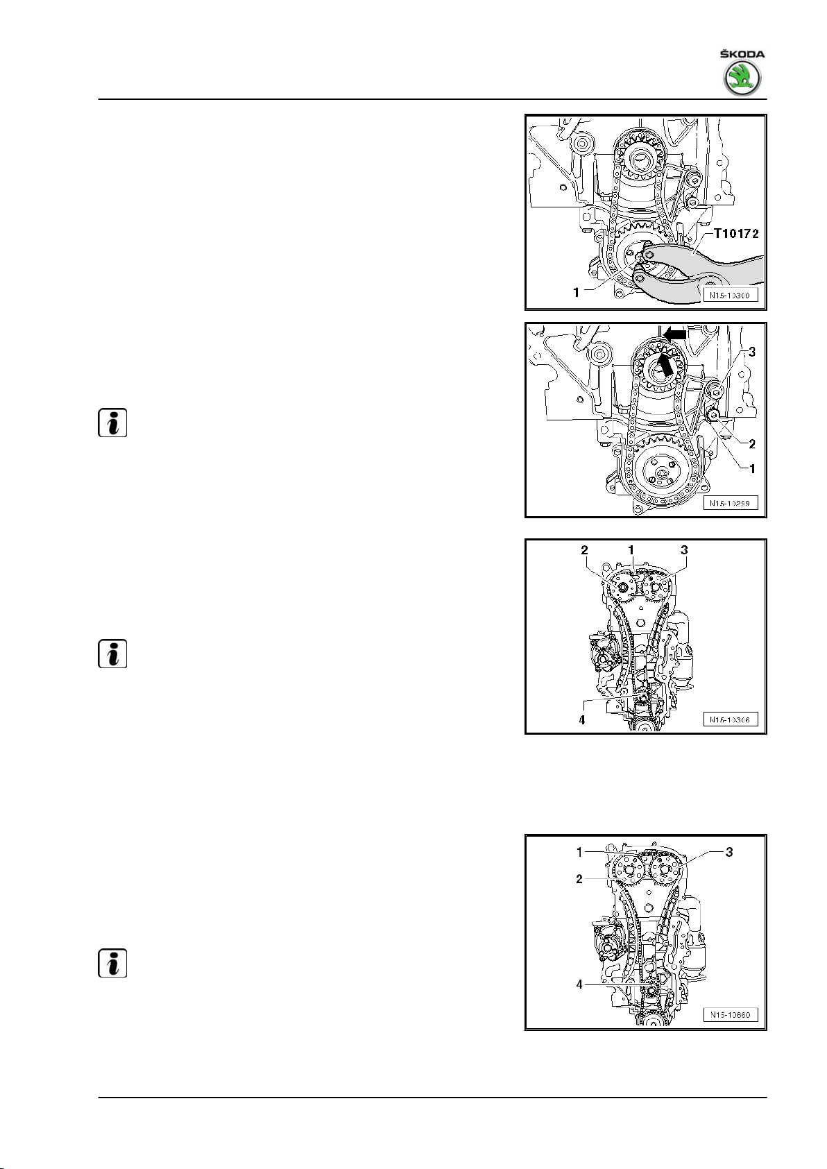
Fabia II 2007 ➤ , Fabia II 2009 ➤ , Fabia II 2011 ➤ , Rapid India 2011 ...
1.6/77 kW MPI engine - Edition 03.2014
– Hold the chain sprocket of the oil pump with the counterholder
- T10172- .
–
Tighten fixing screw -1- to 20 Nm + torque a further 90° (1/
turn).
– Position the chain sprocket onto the drive chain for the oil
pump and tighten the fixing screw -3- to 15 Nm.
– Lever the tensioning spring -1- onto the screw -2- with a screw‐
driver.
Note
♦
Observe the markings -arrows-.
♦
The crankshaft should not turn.
4
For engine with identification characters BTS
– Screw on the chain sprocket -3- by hand with a new fixing
screw.
– Place the timing chain -1- onto the chain sprocket of the crank‐
shaft -4-, the chain sprocket of the outlet camshaft -3- and
screw on the camshaft adjuster -2- with a new fixing screw.
Note
♦
Observe the marking of the running direction on the timing
chain -1-.
♦
Make sure that the guide sleeve is installed between the inlet
camshaft and camshaft adjuster.
♦
On engine with identification characters BTS, the fixing screw
of the camshaft adjuster -2- has a left-hand thread.
For engine with identification characters CFNA, CLSA
– Screw on the chain sprocket -3- by hand with a new fixing
screw.
– Place the timing chain -1- onto the chain sprocket of the crank‐
shaft -4-, the chain sprocket of the outlet camshaft -3- and
screw on the chain sprocket of the inlet camshaft -2- with a
new fixing screw.
Note
Observe the marking of the running direction on the timing chain
-1-.
Continued for all engines
1. Cylinder head 71
Page 78
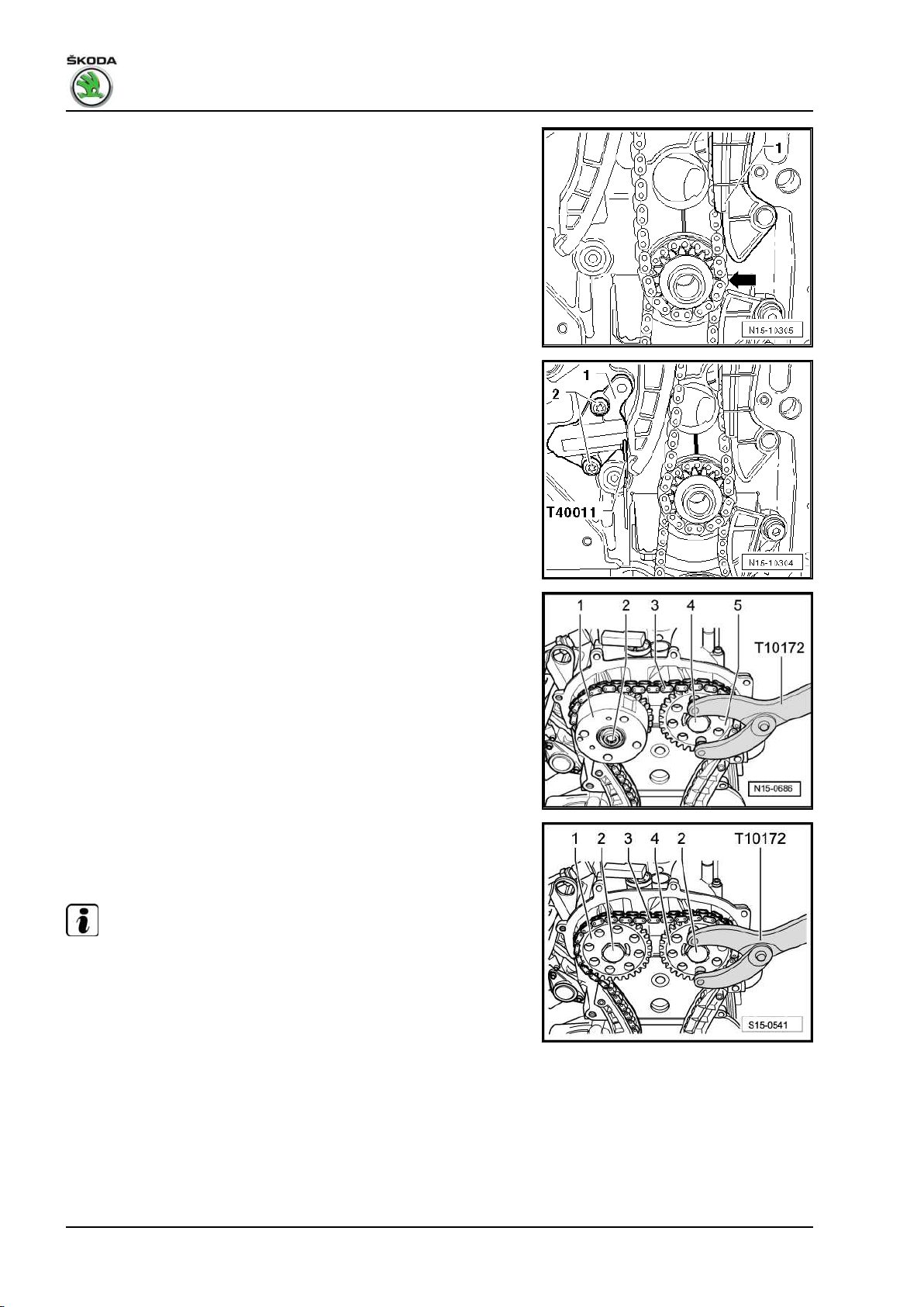
Fabia II 2007 ➤ , Fabia II 2009 ➤ , Fabia II 2011 ➤ , Rapid India 2011 ...
1.6/77 kW MPI engine - Edition 03.2014
The timing chain must rest on the sliding rail -1- and on the chain
sprocket of the crankshaft -arrow-.
– Install the chain tensioner -1- and tighten the fixing screws
-2- to 9 Nm.
– Tighten the timing chain, by pulling out the rig pin - T40011-
from the chain tensioner.
– Check markings on the chain sprocket of the crankshaft and
on the cylinder block; they must be positioned opposite to each
other.
For engine with identification characters BTS
– Tighten the fixing screw -2- to 40 Nm and the screw -4- to 50
Nm (use counterholder - T10172- ).
For engine with identification characters CFNA, CLSA
– Tighten fixing screws -2- to 50 Nm (use counterholder -
T10172- ).
Continued for all engines
Note
♦
First the fixing screws -2- and -4- are tightened to the torquing
angle 90° (1/4 turn), after which the timing is checked.
♦
On engine with identification characters BTS, the fixing screw
of the camshaft adjuster -2- has a left-hand thread.
72 Rep. gr.15 - Cylinder head, valve gear
Page 79

Fabia II 2007 ➤ , Fabia II 2009 ➤ , Fabia II 2011 ➤ , Rapid India 2011 ...
1.6/77 kW MPI engine - Edition 03.2014
– Screw out screws -arrow- and remove the camshaft fixer/lo‐
cator - T10171A- from the camshaft housing.
– Test timing ⇒ page 56 .
If timing is o.k.:
For engine with identification characters BTS
– Hold the camshaft sprockets with the counterholder - T10172-
and torque the fixing screws -2- (left-hand thread) and -4- a
further 90° (1/4 turn) with a rigid wrench.
For engine with identification characters CFNA, CLSA
– Hold the camshaft sprockets with the counterholder - T10172-
and torque the fixing screws -2- a further 90° (1/4 turn) with a
rigid wrench.
Continued for all engines
Note
♦
On engine with identification characters BTS, the fixing screw
of the camshaft adjuster -2- has a left-hand thread.
♦
The camshaft chain sprockets must not turn when tightening.
– Install cover for oil pump gear -1-.
– Install timing case ⇒ page 26 .
The further assembly is carried out in reverse order to disassem‐
bly.
1.9 Removing and installing timing chain
and drive chain of the oil pump for cyl‐
inder head version B
For engine with identification characters CFNA
Special tools and workshop equipment required
♦ Counterholder - T30004 (3415)-
1. Cylinder head 73
Page 80
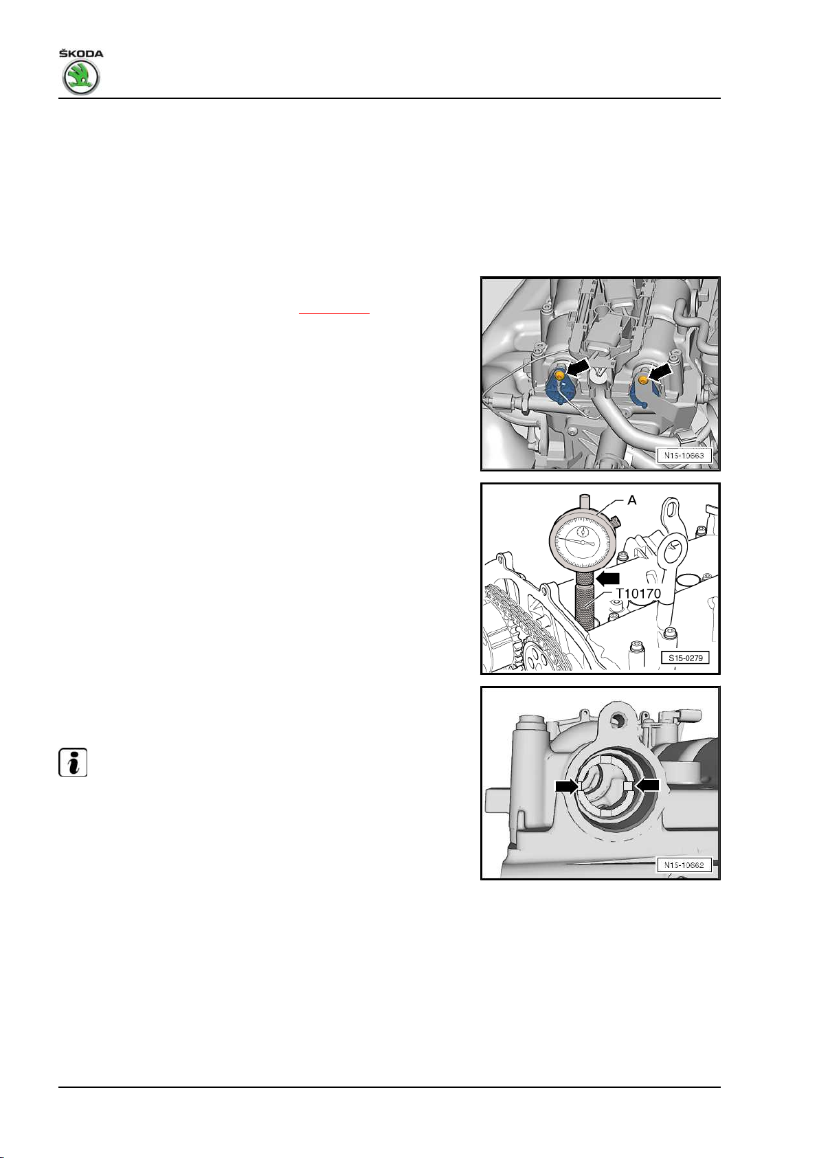
Fabia II 2007 ➤ , Fabia II 2009 ➤ , Fabia II 2011 ➤ , Rapid India 2011 ...
1.6/77 kW MPI engine - Edition 03.2014
♦ Extractor - T10094A♦ Adapter for dial gauge - T10170♦ Fixing bolt - T10414- , 2 pieces
♦ Counterholder - T10172♦ Rig pin - T40011♦ Dial gauge
Removing
– Remove caps -arrows- for camshafts.
– Remove ignition coil from cylinder 1 ⇒ page 184 and release
the spark plug.
– Screw adapter for dial gauge - T10170- up to the stop into the
spark plug thread.
– Insert the dial gauge -A- with extension - T10170/1- up to the
stop and fix in place using the clamping screw -arrow-.
– Rotate the crankshaft in direction of rotation of engine on TDC
for cylinder 1. Note down the position of the small pointer of
the dial gauge.
The holes -arrows- in the camshafts must be positioned as
shown, if necessary rotate the crankshaft a further revolution
(360°).
Note
♦
If the crankshaft was turned more than 0.01 mm past the top
dead centre, the crankshaft must once again be turned approx
45° in the opposite direction of rotation of the engine. Then
position crankshaft in direction of rotation of engine on TDC
for cylinder 1.
♦
Permissible deviation from TDC for cylinder 1: ± 0.01 mm.
– Insert the fixing bolt - T10414- up to the stop into the camshaft
openings.
74 Rep. gr.15 - Cylinder head, valve gear
Page 81
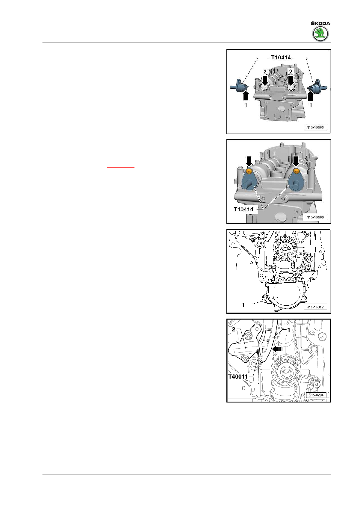
Fabia II 2007 ➤ , Fabia II 2009 ➤ , Fabia II 2011 ➤ , Rapid India 2011 ...
1.6/77 kW MPI engine - Edition 03.2014
The interlocking lugs -arrow 1- must engage in the holes
-arrow 2- of the camshafts.
– To secure the fixing bolts - T10414- , screw in the fixing screws
-arrows- for the caps of the camshafts by hand, do not tighten
forcefully.
– Remove timing case ⇒ page 26 .
– Pull off cover -1- from chain sprocket of oil pump.
– Press the tensioning rail by hand in the
-direction of the arrow- and interlock the piston with the rig pin
- T40011- .
– Remove chain tensioner -2-.
1. Cylinder head 75
Page 82
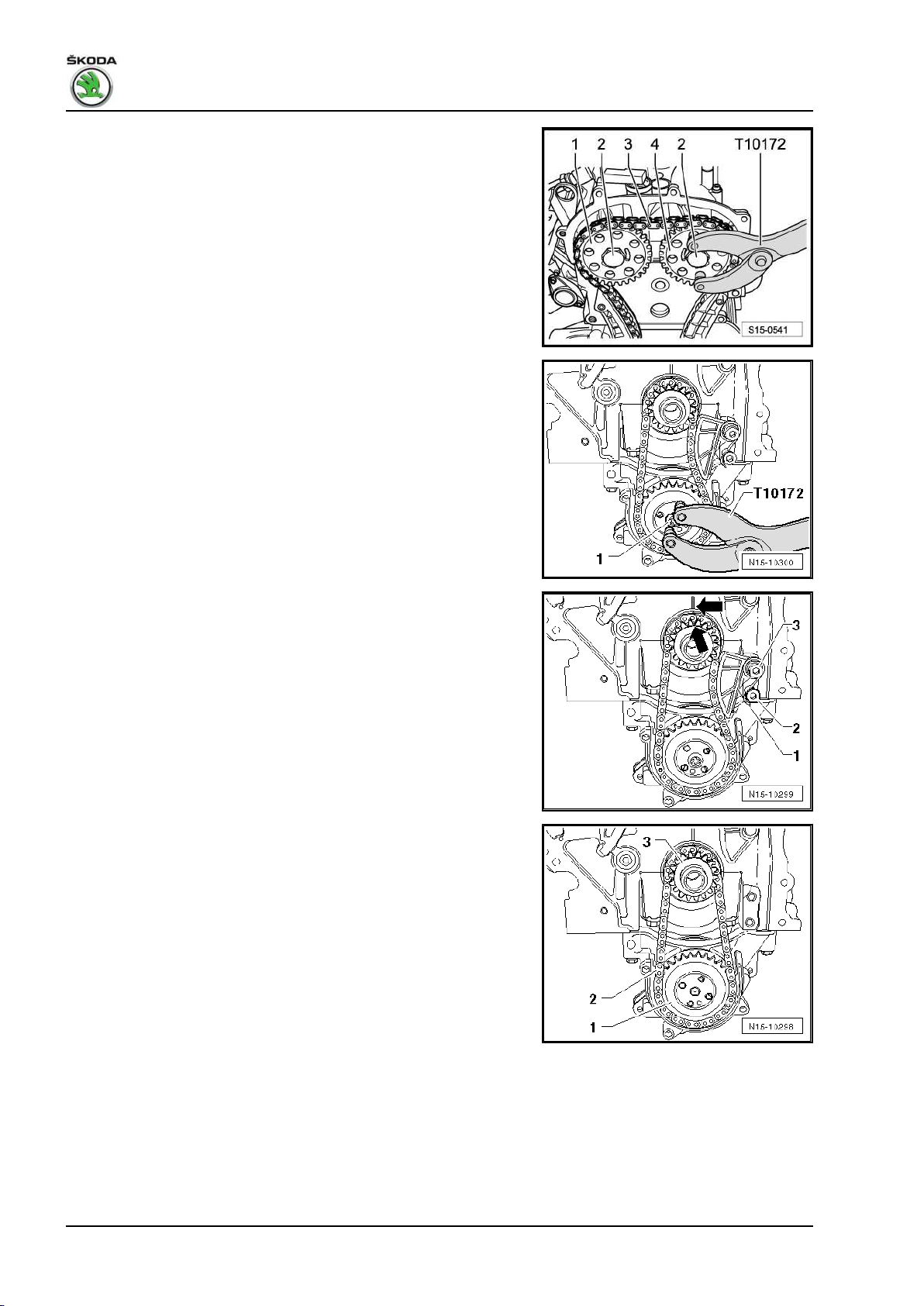
Fabia II 2007 ➤ , Fabia II 2009 ➤ , Fabia II 2011 ➤ , Rapid India 2011 ...
1.6/77 kW MPI engine - Edition 03.2014
– Mark with a suitable felt-tip pen the direction of rotation of the
timing chain -3-.
– Release screws -2- and remove chain sprocket of inlet cam‐
shaft -1- with timing chain -3-. Use counterholder - T10172- to
counterhold.
– Hold chain sprocket of oil pump with counterholder - T10172-
and slacken fixing screw -1-.
– Lever out tensioning spring -1- at the screw -2- with a screw‐
driver and remove tensioning spring -1-.
– Unscrew fixing screw -3- and remove the chain tensioner.
– Mark with a suitable felt-tip pen the direction of rotation of the
drive chain for oil pump -2-.
– Unscrew the fixing screw of the chain sprocket -1- and remove
the chain sprockets -1- and -3- together with the drive chain
for oil pump -2-.
Install
• The crankshaft must be positioned on TDC for cylinder 1.
76 Rep. gr.15 - Cylinder head, valve gear
Page 83
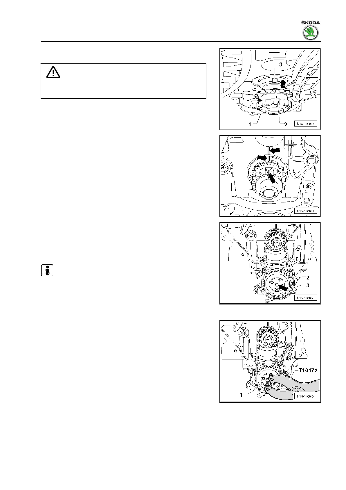
Fabia II 2007 ➤ , Fabia II 2009 ➤ , Fabia II 2011 ➤ , Rapid India 2011 ...
1.6/77 kW MPI engine - Edition 03.2014
– Push chain sprocket -1- in -direction of arrow- up to the stop
onto the crankshaft journal.
Caution
The integrated peg -2- of the chain sprocket -1- must fit into the
slot -3- at the crankshaft stub.
– Mark the positions of the chain sprocket and the crankshaft to
the cylinder block with a felt-tip pen.
– Fit the drive chain for oil pump -3- onto the chain sprocket
-1-.
– Place the chain sprocket of the oil pump -2- into the drive chain
for oil pump -3- and position onto the drive shaft of the oil
pump.
Note
♦
Observe the marking of the running direction on the drive chain
for oil pump.
♦
The chain sprocket of the oil pump only adapts to one postion
on the drive shaft of the oil pump -arrow-.
– Hold the chain sprocket of the oil pump with the counterholder
- T10172- .
– Tighten the new fixing screw -1- to 20 Nm + torque a further
90° (1/4 turn).
1. Cylinder head 77
Page 84
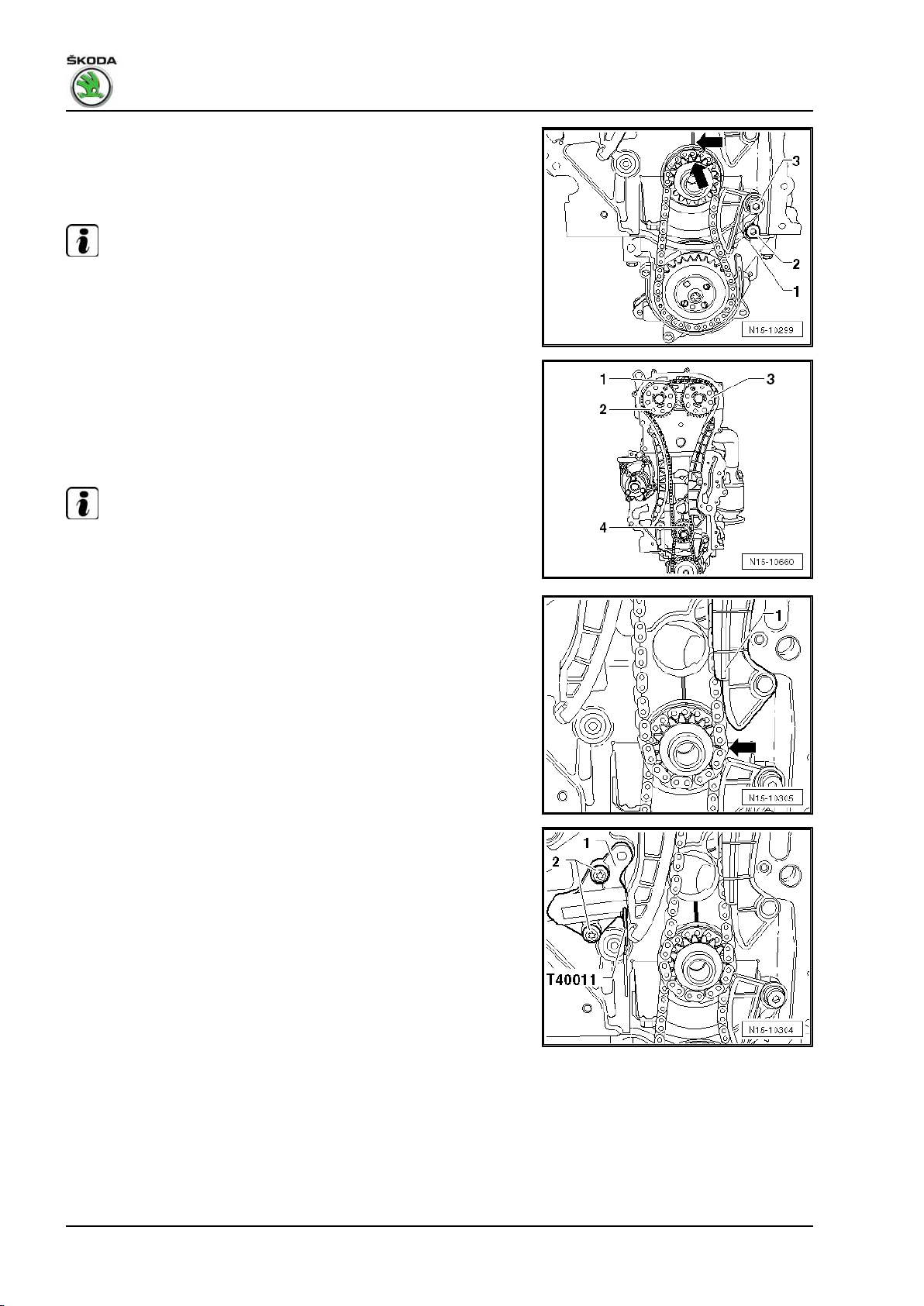
Fabia II 2007 ➤ , Fabia II 2009 ➤ , Fabia II 2011 ➤ , Rapid India 2011 ...
1.6/77 kW MPI engine - Edition 03.2014
– Position the chain sprocket onto the drive chain for the oil
pump and tighten the fixing screw -3- to 15 Nm.
– Lever the tensioning spring -1- onto the screw -2- with a screw‐
driver.
Note
♦
Observe the markings -arrows-.
♦
The crankshaft should not turn.
– Screw on the chain sprocket -3- by hand with a new fixing
screw.
– Place the timing chain -1- onto the chain sprocket of the crank‐
shaft -4-, the chain sprocket of the outlet camshaft -3- and
screw on the chain sprocket of the inlet camshaft -2- with a
new fixing screw.
Note
Observe the marking of the running direction on the timing chain
-1-.
The timing chain must rest on the sliding rail -1- and on the chain
sprocket of the crankshaft -arrow-.
– Install the chain tensioner -1- and tighten the fixing screws
-2- to 9 Nm.
– Tighten the timing chain, by pulling out the rig pin - T40011-
from the chain tensioner.
– Check markings on the chain sprocket of the crankshaft and
on the cylinder block; they must be positioned opposite to each
other.
78 Rep. gr.15 - Cylinder head, valve gear
Page 85
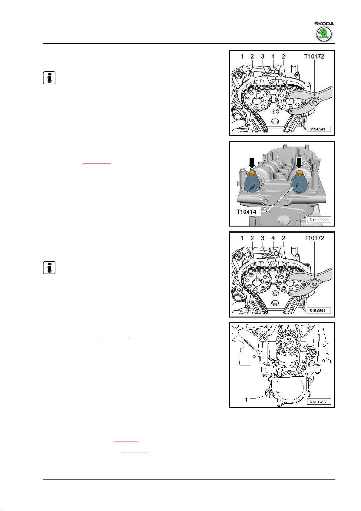
Fabia II 2007 ➤ , Fabia II 2009 ➤ , Fabia II 2011 ➤ , Rapid India 2011 ...
1.6/77 kW MPI engine - Edition 03.2014
– Tighten fixing screws -2- to 50 Nm (use counterholder -
T10172- ).
Note
First the fixing screws -2- are tightened to the torquing angle 90°
(1/4 turn), after which the timing is checked.
– Unscrew the securing screws -arrows- and remove both fixing
bolts - T10414- .
– Test timing ⇒ page 57 .
If timing is o.k.:
– Hold the camshaft sprockets with the counterholder - T10172-
and torque the fixing screws -2- a further 90° (1/4 turn) with a
rigid wrench.
Note
The camshaft chain sprockets must not turn when tightening.
– Install cover for oil pump gear -1-.
– Install timing case ⇒ page 26 .
The further assembly is carried out in reverse order to disassem‐
bly.
1.10 Removing and installing camshaft hous‐
ing
Observe safety measures ⇒ page 4 .
Observe rules for cleanliness ⇒ page 4 .
Special tools and workshop equipment required
1. Cylinder head 79
Page 86
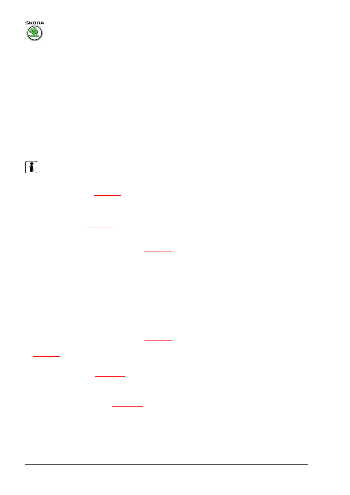
Fabia II 2007 ➤ , Fabia II 2009 ➤ , Fabia II 2011 ➤ , Rapid India 2011 ...
1.6/77 kW MPI engine - Edition 03.2014
♦ Camshaft fixer/locator - T10171A- , for cylinder head version
A
♦ Fixing bolt - T10414- , 2 pieces, for cylinder head version B
♦ Two pin screws (M6 x 80)
♦ Sealant - D 188 003 A1♦ Sealant remover gasket stripper (bearing code GST, bearing
article no. R 34402), manufacturer Retech s.r.o.
♦ Cleaning and degreasing agent, e.g. - D 009 401 04♦ Protective goggles and gloves
Removing
• The ignition must be switched off and the ignition key must be
withdrawn.
Note
♦
On this engine the camshafts are located in the camshaft
housing. Before removing the camshaft housing, the timing
case must be removed ⇒ page 26 .
♦
Do not rework the sealing surface of the camshaft housing.
♦
The camshafts must only be replaced complete with camshaft
housing for the cylinder head version -B-. Distinguishing fea‐
tures of the engines ⇒ page 52 .
♦
Removing and installing camshafts:
♦ Engines with identification characters BTS ⇒ page 87 .
♦ Engines with identification characters CFNA, CLSA, version A
⇒ page 89 .
♦ Engines with identification characters CFNA, version B
⇒ page 92 .
– Remove plastic cover for camshaft housing.
– Remove timing case ⇒ page 26 .
– Position the crankshaft on TDC for cylinder 1, then turn back
the crankshaft approx. 45° in the opposite direction of rotation
of the engine and remove the camshaft chain sprockets with
the timing chain:
♦ Engines with identification characters BTS ⇒ page 20 .
♦ Engines with identification characters CFNA, CLSA
⇒ page 23 .
– Unscrew earth lead from camshaft housing.
– Removing ignition coils ⇒ page 184 .
– Remove cable guide with wiring loom from camshaft housing.
– Pull out oil dipstick.
– Removing the intake manifold ⇒ page 159 .
– Unscrew left lifting eye.
– Slacken the bolts of the camshaft housing crosswise from the
outside to the inside.
– Release screws and remove camshaft housing.
80 Rep. gr.15 - Cylinder head, valve gear
Page 87
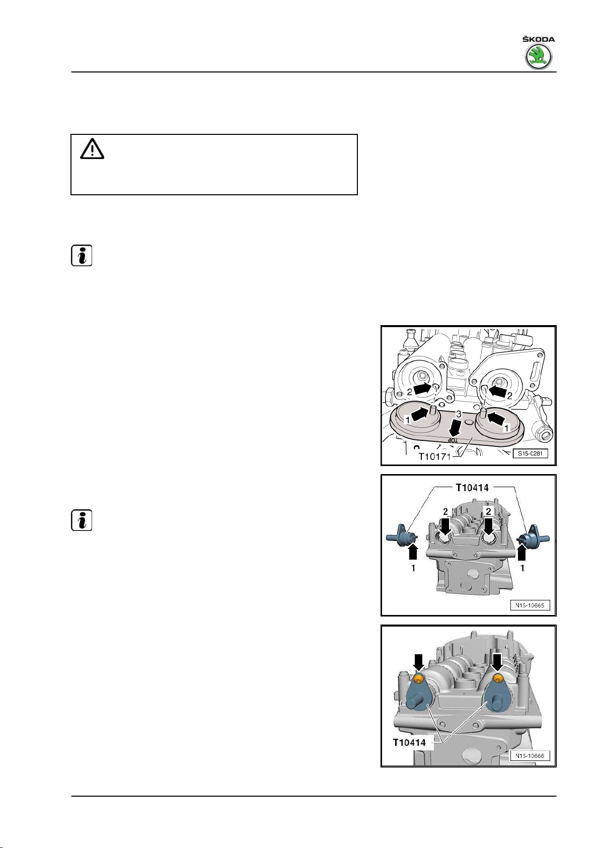
Fabia II 2007 ➤ , Fabia II 2009 ➤ , Fabia II 2011 ➤ , Rapid India 2011 ...
1.6/77 kW MPI engine - Edition 03.2014
Install
Condition
• The pistons must not be positioned at top dead centre.
WARNING
Wear protective gloves when working with sealant and grease
remover!
– Remove residual sealant on the cylinder head and camshaft
housing using a chemical sealant remover.
Note
Ensure that no dirt and sealant residues get into the cylinder head
or camshaft housing.
Cylinder head version A
– Turn the inlet and outlet camshaft until the camshaft fixer/lo‐
cator - T10171A- can be inserted up to the stop into the holes
of the camshafts.
– To secure the camshaft fixer/locator - T10171A- screw in M6
screw by hand; do not tighten.
Cylinder head version B
– Turn the camshafts until the fixing bolts - T10414- slide into
the inlet and outlet camshafts up to the stop.
The interlocking lugs -arrow 1- must engage in the holes
-arrow 2- of the camshafts.
Note
When turning, the camshafts must not be moved axially.
– To secure the fixing bolts - T10414- , screw in the fixing screws
-arrows- for the caps of the camshafts by hand, do not tighten
forcefully.
Continued for all engines
– Carefully clean and degrease the sealing surfaces. They must
be free of oil and grease.
1. Cylinder head 81
Page 88
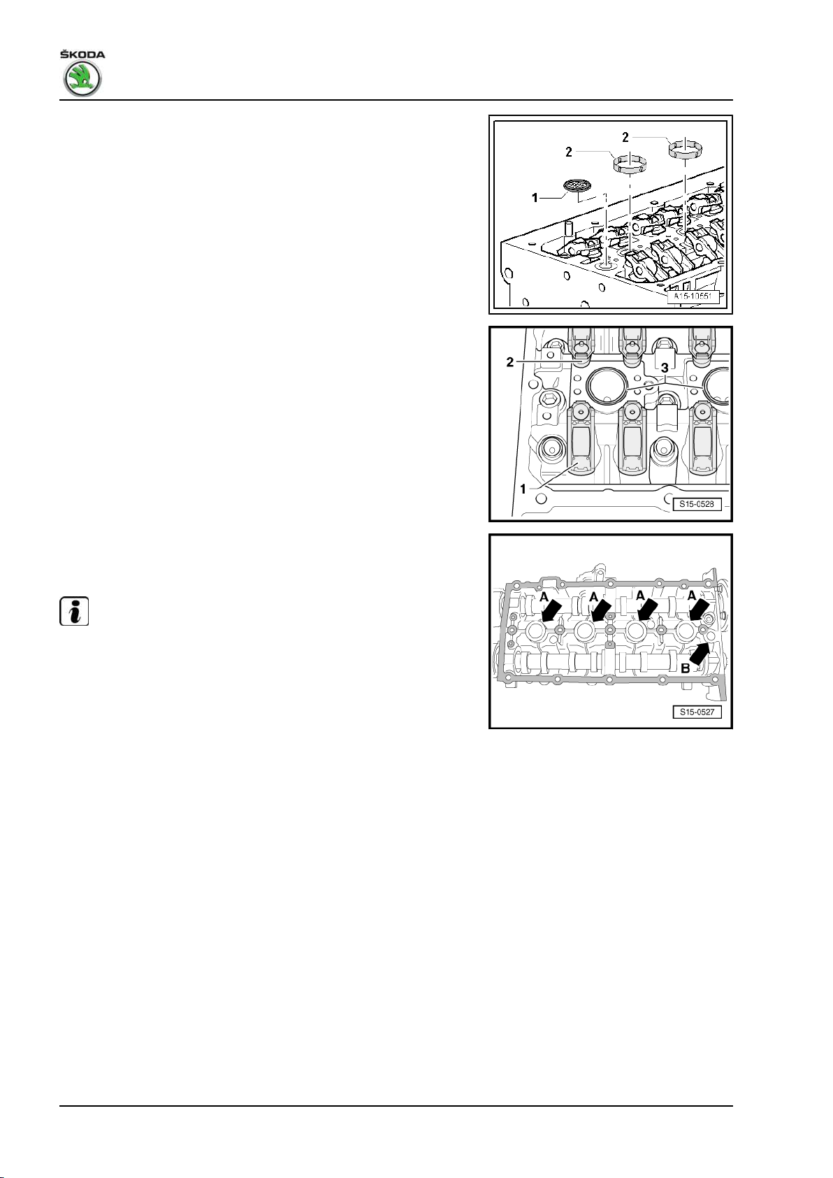
Fabia II 2007 ➤ , Fabia II 2009 ➤ , Fabia II 2011 ➤ , Rapid India 2011 ...
1.6/77 kW MPI engine - Edition 03.2014
– Replace oil strainer -1- and insert in the cylinder head.
– Insert 4 new gasket rings -2- into the grooves of the cylinder
head.
– Ensure that all the roller arms are correctly positioned on the
valve stem ends -1- and are clipped in place on the relevant
hydraulic supporting elements -2-.
– Screw in two pin screws (M6 x 80) into the cylinder head before
fitting on the camshaft housing.
– Apply a thin coating of sealant uniformly on the clean sealing
surface of the camshaft housing (see grid surfaces in the il‐
lustration).
Note
♦
Do not apply sealant in the area of the -arrows A-. Here the
cylinder head is sealed with the inserted gasket rings.
♦
No sealant must be applied in the area -arrow B-. Here the oil
strainer seals.
♦
The sealant must not be applied too thickly, as otherwise ex‐
cess sealant may penetrate into the oil bores and possibly
cause engine damage.
82 Rep. gr.15 - Cylinder head, valve gear
Page 89
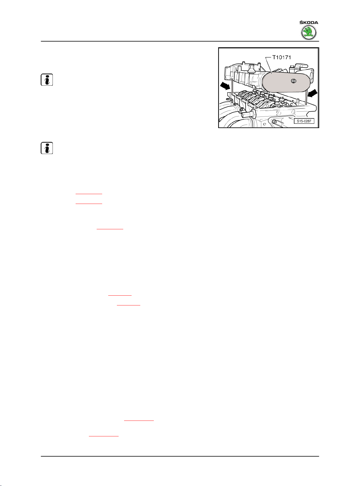
Fabia II 2007 ➤ , Fabia II 2009 ➤ , Fabia II 2011 ➤ , Rapid India 2011 ...
1.6/77 kW MPI engine - Edition 03.2014
– Carefully place the camshaft housing vertically from above
onto the pin screws -arrows- and the dowel pins of the cylinder
head.
Note
Make sure that no residues of oil drop down onto the sealing
flange and the camshaft housing does not tilt.
– Tighten the new fixing screws of the camshaft housing diago‐
nally and evenly from the inside to the outside.
Tightening torque: 10 Nm + torque a further 90° (1/4 turn)
Note
After installing the camshaft housing, allow the sealant to dry for
about 30 minutes.
– Setting the timing:
♦ Version A ⇒ page 59 .
♦ Version B ⇒ page 63 .
The further assembly is carried out in reverse order to disassem‐
bly. Pay attention to the following:
♦ Install timing case ⇒ page 26 .
♦ Pay attention to the required measures after connecting the
battery ⇒ Electrical System; Rep. gr. 27 .
♦ Interrogate fault memory, rectify any faults existing and erase
the fault memory ⇒ Vehicle diagnostic tester.
1.11 Removing and installing the cylinder
head
Observe safety measures ⇒ page 3 .
Observe rules for cleanliness ⇒ page 4 .
Special tools and workshop equipment required
♦ Supporting device - MP9-200 (10-222A)♦ Hook - MP9-200/10 (10-222A/10)♦ Support - T10358♦ Sealant remover gasket stripper (bearing code GST, bearing
article no. R 34402), manufacturer Retech s.r.o.
♦ Protective goggles and gloves
Condition
• The engine must not exceed the temperature of 35 °C, be‐
cause the cylinder head could twist when loosening the cylin‐
der head screws.
Removing
– Remove the air filter housing ⇒ page 161 .
– Drain the coolant from the cooling system and the charge air
cooling system ⇒ page 118 .
– Remove fuel strip together with injectors.
1. Cylinder head 83
Page 90

Fabia II 2007 ➤ , Fabia II 2009 ➤ , Fabia II 2011 ➤ , Rapid India 2011 ...
1.6/77 kW MPI engine - Edition 03.2014
– Removing the intake manifold ⇒ page 159 .
– Position the supporting device - MP9-200 (10-222A)- with two
hooks - MP9-200/10- .
– Hook the right hook into the right lifting eye of the engine and
pre-tension via the spindle, however do not raise.
– First of all do not attach the left hook.
– Remove timing case ⇒ page 26 .
– Remove timing chain and drive chain for oil pump:
♦ Version A ⇒ page 67 .
♦ Version B ⇒ page 73 .
– Remove coolant regulator housing from cylinder head
⇒ page 116 .
– Remove exhaust manifold:
♦ Fabia II and Roomster vehicles with engine identification char‐
acters BTS ⇒ page 171 .
♦ Fabia II and Roomster vehicles with engine identification char‐
acters CFNA ⇒ page 172 .
♦ Fabia II vehicles with engine identification characters CLSA
⇒ page 174
♦ Rapid NH, NK vehicles with engine identification characters
CFNA ⇒ page 175
♦ Rapid NA vehicles with engine identification characters CLSA
⇒ page 175
– Unscrew the fixing screw for the gearbox and screw down the
bracket - T10358- as shown.
– Hang the hook of the supporting device - MP9-200- at the
bracket - T10358- as shown.
– Turn the spindle until the hook is slightly tensioned.
– Unhook the hook -1- from the right lifting eye and push the
spindle onto the supporting device - MP9-200- on the right.
– Removing the camshaft housing ⇒ page 79 .
– Remove the roller rocker arm together with the supporting el‐
ements and lay aside on a clean surface.
– Ensure that the roller rocker arms and the balancing elements
are not mixed up.
84 Rep. gr.15 - Cylinder head, valve gear
Page 91
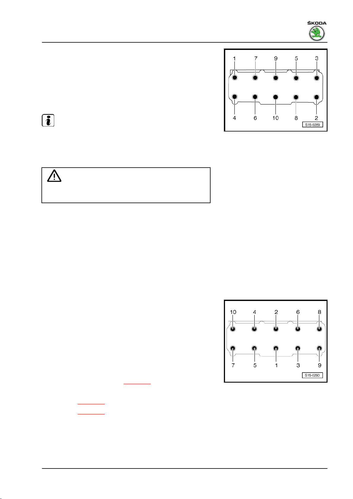
Fabia II 2007 ➤ , Fabia II 2009 ➤ , Fabia II 2011 ➤ , Rapid India 2011 ...
1.6/77 kW MPI engine - Edition 03.2014
– Release the cylinder head bolts in the specified sequence and
remove.
– Carefully remove the cylinder head.
Install
Condition
• The pistons must not be positioned at top dead centre.
Note
♦
Remove the new cylinder head gasket from its wrapping im‐
mediately before fitting.
♦
Treat the new seal with the utmost care. Any damage will result
in leaks.
WARNING
Wear protective googles and gloves when working with sealant
and grease remover!
– Fill up the cylinder with clean cloths to prevent any dirt from
getting between the cylinder barrel and the piston.
– Remove residual sealant on the contact surfaces of the cylin‐
der head/cylinder block using a chemical sealant remover.
– Set pistons for cyl. 1 to TDC and turn back crankshaft slightly.
– Position the new cylinder heads. The text (part number) must
be legible from above.
– Insert the cylinder head. Pay attention to the dowel pins in the
cylinder block.
– Insert new cylinder head bolts and first tighten by hand.
– Tighten cylinder head bolts in the tightening order shown as
follows:
♦ Tighten all screws to 30 Nm.
♦
Then, torque all bolts further to 90° (1/4 turn) with a rigid
wrench.
♦
Finally, once again turn all bolts through a further 90° (1/4 turn).
– Insert the supporting elements in the cylinder head and posi‐
tion the relevant roller rocker arms on the valve stem ends and
the supporting elements.
– Installing camshaft housing ⇒ page 79 .
– Setting the timing:
♦ Version A ⇒ page 59 .
♦ Version B ⇒ page 63 .
The further assembly is carried out in reverse order to disassem‐
bly.
1.12 Testing the compression
Special tools and workshop equipment required
1. Cylinder head 85
Page 92

Fabia II 2007 ➤ , Fabia II 2009 ➤ , Fabia II 2011 ➤ , Rapid India 2011 ...
1.6/77 kW MPI engine - Edition 03.2014
♦ Compression tester , e.g. -V.A.G 1763Test condition
Oil temperature min. 30 ℃
Test sequence
– Remove cover for camshaft housing.
– Remove the ignition coils and spark plugs ⇒ page 184 .
– Take off the cover in front of the fuse carrier below the dash
panel and take the fuse for the voltage supply of the injection
valves out of the fuse carrier in the dash panel ⇒ Current flow
diagrams, Electrical fault finding and Fitting locations.
– Check compression pressure using the compression tester.
Note
Use of tester ⇒ Operating Instructions .
– Operate starter until the tester no longer indicates a pressure
rise.
Compression readings
New engine Wear limit Difference
between cylinders
1 - 1.5 MPa
(10 - 15 bar)
– Screw in the spark plug with spark plug wrench and then tight‐
en fully to 30 Nm.
Further installation occurs in reverse order.
– Interrogate fault memory, rectify any faults existing and erase
the fault memory ⇒ Vehicle diagnostic tester.
0.7 MPa
(7 bar)
0.3 MPa
(3 bar)
86 Rep. gr.15 - Cylinder head, valve gear
Page 93

Fabia II 2007 ➤ , Fabia II 2009 ➤ , Fabia II 2011 ➤ , Rapid India 2011 ...
1.6/77 kW MPI engine - Edition 03.2014
2 Valve gear
2.1 Valve gear - Summary of components (version A)
For engine with identification characters BTS
1 - 40 Nm + torque a further 90°
(1/4 turn)
❑ Left-hand thread
❑ replace
2 - 50 Nm + torque a further 90°
(1/4 turn)
3 - Camshaft adjuster
❑ for inlet valves
❑ with chain sprocket
❑ Observe the fitting posi‐
tion of the timing chain
❑ must not be disassem‐
bled
❑ removing and installing
⇒ page 59
4 - Sprocket
❑ for exhaust camshaft
❑ Observe the fitting posi‐
tion of the timing chain
5 - Camshaft adjustment valve
1 - N205-
6 - 10 Nm
7 - O-ring
❑ replace if damaged
❑ oil before the assembly
8 - 10 Nm + torque a further 90°
(1/4 turn)
❑ replace
❑ tighten from inside to
outside
9 - Camshaft housing
❑ removing and installing ⇒ page 79
10 - Roller rocker arm
❑ inspect roller bearings of roller for smooth operation
❑ oil contact surfaces
❑ for installing, clip onto the supporting element and secure with locking clip
11 - Valve collets
12 - Supporting element
❑ do not interchange
❑ with hydraulic valve clearance compensation
❑ before installing check axial play of the camshaft ⇒ page 89
2. Valve gear 87
Page 94

Fabia II 2007 ➤ , Fabia II 2009 ➤ , Fabia II 2011 ➤ , Rapid India 2011 ...
1.6/77 kW MPI engine - Edition 03.2014
❑ oil contact surfaces
13 - Valve spring retainer
14 - Valve spring
❑ removing and installing ⇒ page 97
15 - Valve stem seal
❑ replace ⇒ page 97
16 - Valve guide
❑ not to be replaced
❑ check ⇒ page 96
17 - Cylinder head
❑ reworking valve seats ⇒ page 93
❑ reworking sealing surface ⇒ page 88
18 - Valves
❑ do not rework, only grinding in with grinding paste is permissible
❑ Valve dimensions ⇒ page 89
19 - Support
20 - Screw cap
❑ for hole of inlet camshaft
21 - Screw cap
❑ for hole of exhaust camshaft
22 - Exhaust camshaft
❑ do not mix up with inlet camshaft
❑ Inspecting axial play ⇒ page 89
❑ moisten with oil before installing (also axial bearing collar)
23 - Inlet camshaft
❑ do not mix up with exhaust camshaft
❑ Inspecting axial play ⇒ page 89
❑ moisten with oil before installing (also axial bearing collar)
24 - Guide bushing
Reworking cylinder head sealing surface
Reworking dimension of cylinder head: -a- at least 108.25 mm
Note
If the sealing surface is reworked, the valves should be set lower
by the same amount (rework valve seat rings) otherwise the
valves will strike the pistons. When doing this, ensure that the
permissible minimum dimension - ⇒ page 94 - is maintained.
88 Rep. gr.15 - Cylinder head, valve gear
Page 95

Fabia II 2007 ➤ , Fabia II 2009 ➤ , Fabia II 2011 ➤ , Rapid India 2011 ...
1.6/77 kW MPI engine - Edition 03.2014
Checking the axial play of the camshaft
Special tools and workshop equipment required
♦ Universal dial gauge holder - MP3-447 (VW 387)♦ Dial gauge
Carry out measurement with the camshaft housing removed and
the end covers installed.
Wear limit: max. 0.4 mm
Valve dimensions
Note
Valves must not be reworked. Only grinding in with grinding paste
in the valve seat is permissible.
Dimension Inlet valve Exhaust valve
∅ a mm 29.5 26.0
∅ b mm 5.973 5.953
c mm 100.9 100.5
α ∠° 45 45
2.2 Valve gear - Summary of components (version A)
For engine with identification characters CFNA, CLSA
2. Valve gear 89
Page 96
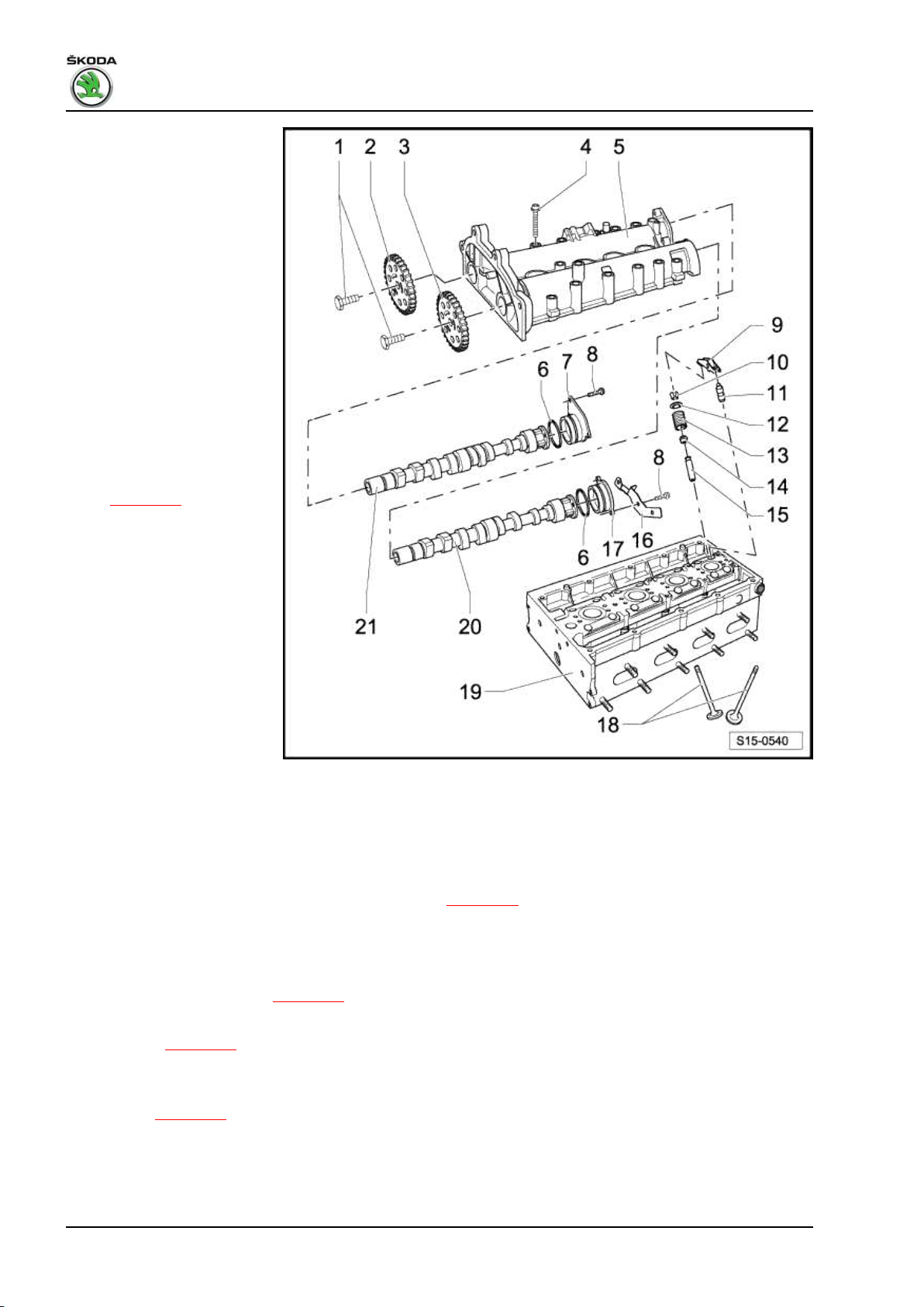
Fabia II 2007 ➤ , Fabia II 2009 ➤ , Fabia II 2011 ➤ , Rapid India 2011 ...
1.6/77 kW MPI engine - Edition 03.2014
1 - 50 Nm + torque a further 90°
(1/4 turn)
2 - Sprocket
❑ for inlet camshaft
❑ Observe the fitting posi‐
tion of the timing chain
3 - Sprocket
❑ for exhaust camshaft
❑ Observe the fitting posi‐
tion of the timing chain
4 - 10 Nm + torque a further 90°
(1/4 turn)
❑ replace
❑ tighten from inside to
outside
5 - Camshaft housing
❑ removing and installing
⇒ page 79
6 - O-ring
❑ replace
❑ oil before the assembly
7 - Screw cap
❑ for hole of inlet camshaft
8 - 10 Nm
9 - Roller rocker arm
❑ inspect roller bearings
of roller for smooth op‐
eration
❑ oil contact surfaces
❑ for installing, clip onto
the supporting element and secure with locking clip
10 - Valve collets
11 - Supporting element
❑ do not interchange
❑ with hydraulic valve clearance compensation
❑ before installing check axial play of the camshaft ⇒ page 91
❑ oil contact surfaces
12 - Valve spring retainer
13 - Valve spring
❑ removing and installing ⇒ page 97
14 - Valve stem seal
❑ replace ⇒ page 97
15 - Valve guide
❑ not to be replaced
❑ check ⇒ page 96
16 - Support
17 - Screw cap
❑ for hole of exhaust camshaft
90 Rep. gr.15 - Cylinder head, valve gear
Page 97
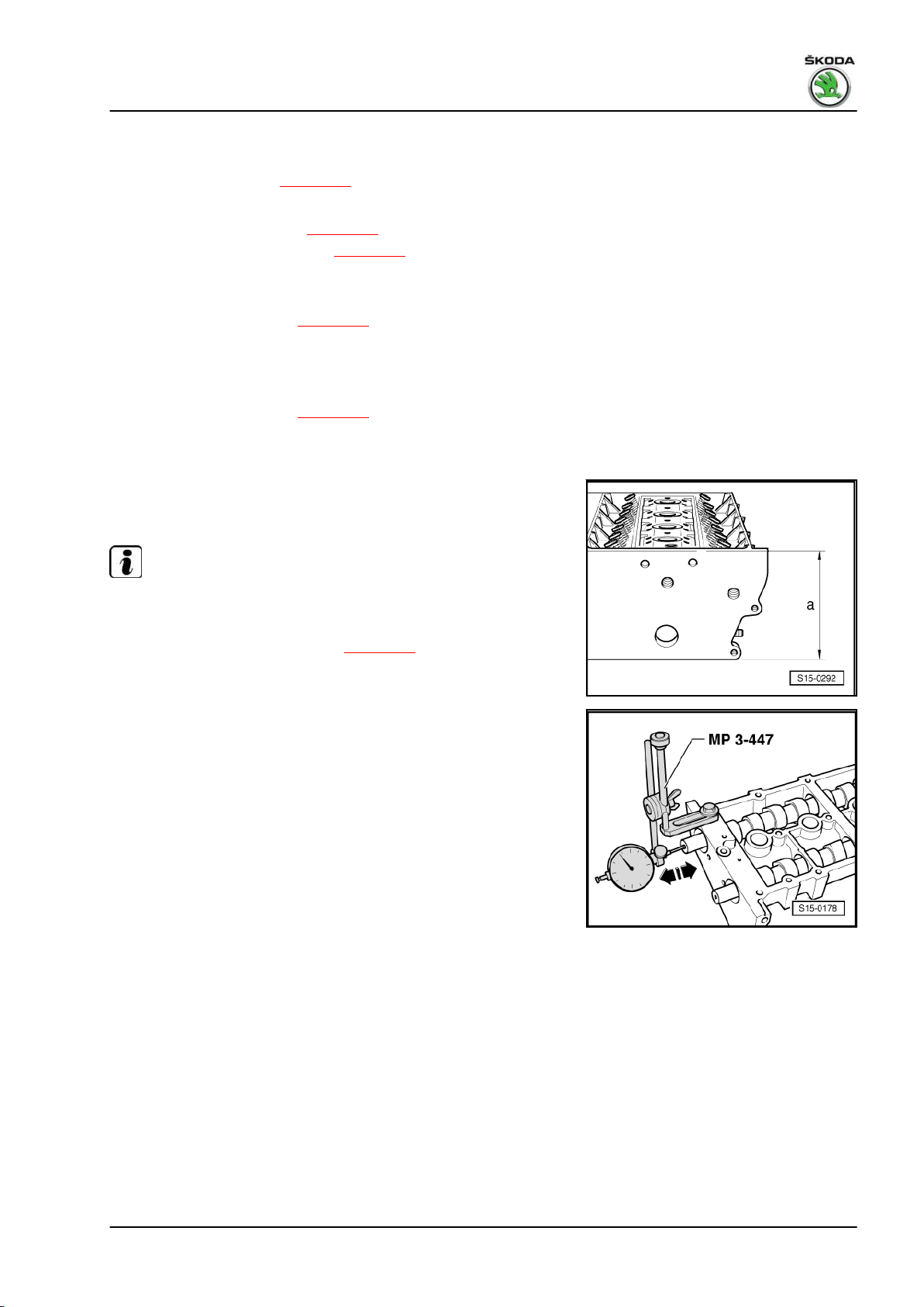
Fabia II 2007 ➤ , Fabia II 2009 ➤ , Fabia II 2011 ➤ , Rapid India 2011 ...
1.6/77 kW MPI engine - Edition 03.2014
18 - Valves
❑ do not rework, only grinding in with grinding paste is permissible
❑ Valve dimensions ⇒ page 92
19 - Cylinder head
❑ reworking valve seats ⇒ page 93
❑ reworking sealing surface ⇒ page 91
20 - Exhaust camshaft
❑ do not mix up with inlet camshaft
❑ Inspecting axial play ⇒ page 91
❑ moisten with oil before installing (also axial bearing collar)
21 - Inlet camshaft
❑ do not mix up with exhaust camshaft
❑ Inspecting axial play ⇒ page 91
❑ moisten with oil before installing (also axial bearing collar)
Reworking cylinder head sealing surface
Reworking dimension of cylinder head: -a- at least 108.25 mm
Note
If the sealing surface is reworked, the valves should be set lower
by the same amount (rework valve seat rings) otherwise the
valves will strike the pistons. When doing this, ensure that the
permissible minimum dimension - ⇒ page 94 - is maintained.
Checking the axial play of the camshaft
Special tools and workshop equipment required
♦ Universal dial gauge holder - MP3-447 (VW 387)-
♦ Dial gauge
Carry out measurement with the camshaft housing removed and
the end covers installed.
2. Valve gear 91
Page 98
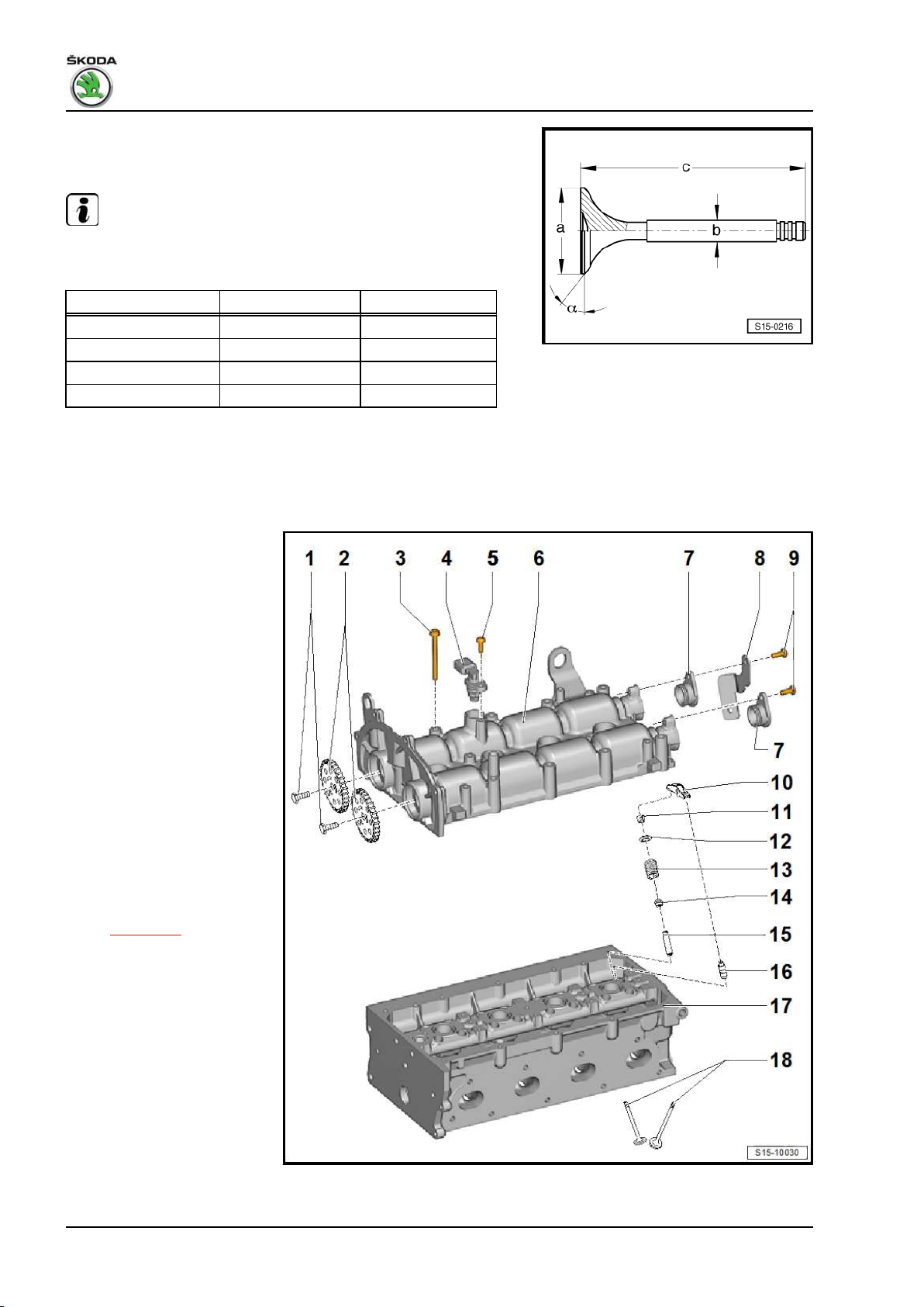
Fabia II 2007 ➤ , Fabia II 2009 ➤ , Fabia II 2011 ➤ , Rapid India 2011 ...
1.6/77 kW MPI engine - Edition 03.2014
Wear limit: max. 0.4 mm
Valve dimensions
Note
Valves must not be reworked. Only grinding in with grinding paste
in the valve seat is permissible.
Dimension Inlet valve Exhaust valve
∅ a mm 29.5 26.0
∅ b mm 5.973 5.953
c mm 100.9 100.5
α ∠° 45 45
2.3 Valve gear - Summary of components (version B)
For engine with identification characters CFNA
1 - 50 Nm + torque a further 90°
(1/4 turn)
2 - Sprocket
❑ for inlet / outlet camshaft
❑ Observe the fitting posi‐
tion of the timing chain
3 - 10 Nm + torque a further 90°
(1/4 turn)
❑ replace
❑ tighten from inside to
outside
4 - Hall sender - G40-
❑ with O-ring
❑ replace the O-ring if it is
damaged
5 - 10 Nm
6 - Camshaft housing
❑ removing and installing
⇒ page 79
7 - Screw cap
❑ for hole of camshaft
8 - Support
9 - 10 Nm
10 - Roller rocker arm
❑ inspect roller bearings
of roller for smooth op‐
eration
❑ oil contact surfaces
❑ for installing, clip onto
the supporting element
and secure with locking clip
92 Rep. gr.15 - Cylinder head, valve gear
Page 99
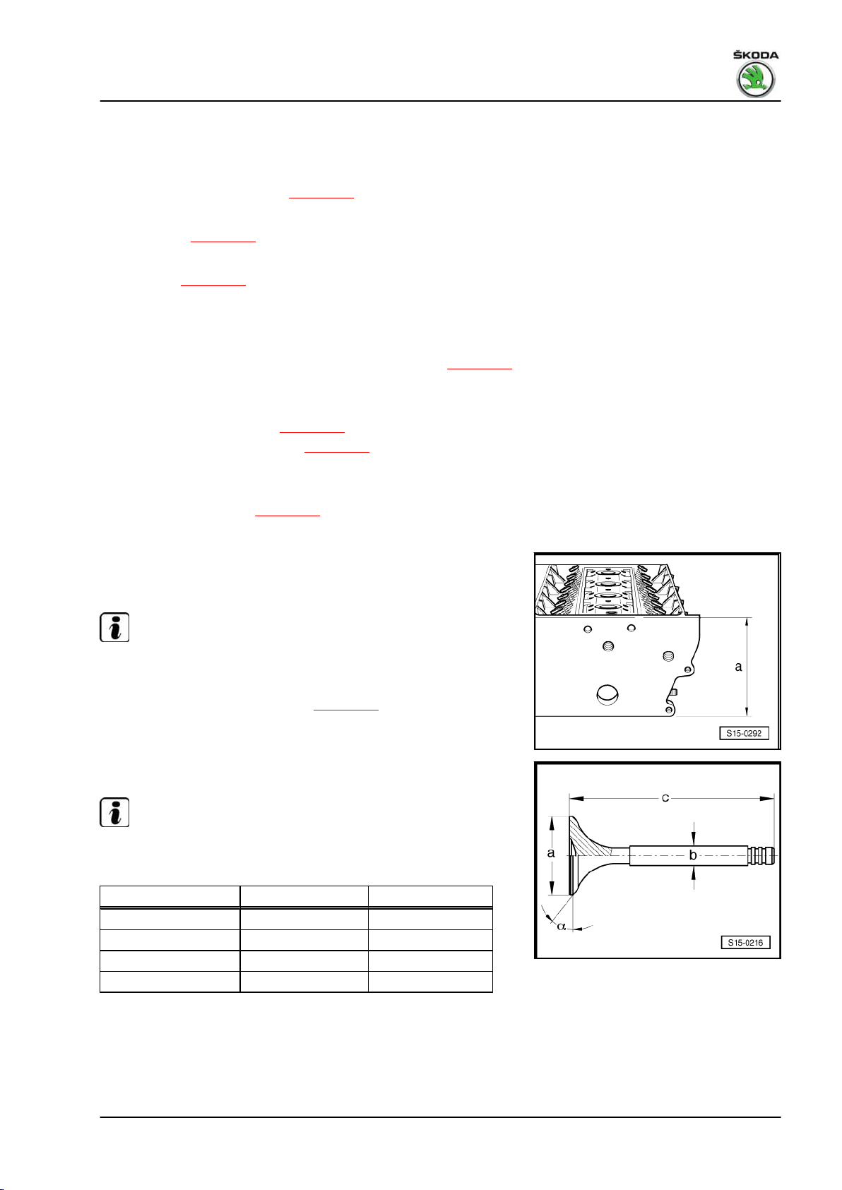
Fabia II 2007 ➤ , Fabia II 2009 ➤ , Fabia II 2011 ➤ , Rapid India 2011 ...
1.6/77 kW MPI engine - Edition 03.2014
11 - Valve collets
12 - Valve spring retainer
13 - Valve spring
❑ removing and installing ⇒ page 97
14 - Valve stem seal
❑ replace ⇒ page 97
15 - Valve guide
❑ check ⇒ page 96
16 - Supporting element
❑ do not interchange
❑ with hydraulic valve clearance compensation
❑ before installing check axial play of the camshaft ⇒ page 91
❑ oil contact surfaces
17 - Cylinder head
❑ reworking valve seats ⇒ page 93
❑ reworking sealing surface ⇒ page 93
18 - Valves
❑ do not rework, only grinding in with grinding paste is permissible
❑ Valve dimensions ⇒ page 93
Reworking cylinder head sealing surface
Reworking dimension of cylinder head: -a- at least 108.25 mm
Note
If the sealing surface is reworked, the valves should be set lower
by the same amount (rework valve seat rings) otherwise the
valves will strike the pistons. When doing this, ensure that the
permissible minimum dimension - ⇒ page 94 - is maintained.
Valve dimensions
Note
Valves must not be reworked. Only grinding in with grinding paste
in the valve seat is permissible.
Dimension Inlet valve Exhaust valve
∅ a mm 29.5 26.0
∅ b mm 5.973 5.953
c mm 100.9 100.5
α ∠° 45 45
2.4 Reworking valve seats
Special tools and workshop equipment required
♦ Grinding paste
2. Valve gear 93
Page 100

Fabia II 2007 ➤ , Fabia II 2009 ➤ , Fabia II 2011 ➤ , Rapid India 2011 ...
1.6/77 kW MPI engine - Edition 03.2014
♦ Caliper gauge
♦ Milling cutter kit for reworking valve seats
Note
♦
Only use milling cutters with carbide metal tips (min. 90 HRC).
♦
When carrying out repairs on engines with leaking valves, it is
not sufficient to machine or replace the valve seats and valves.
It is also necessary to inspect the valve guides for wear, par‐
ticularly on engines with a high mileage ⇒ page 96 .
♦
Rework valve seats only sufficiently in order to obtain a proper
contact pattern. Calculate the maximum permissible rework‐
ing dimension before commencing. If the reworking dimension
is exceeded, the proper operation of the hydraulic valve clear‐
ance compensation is no longer ensured. If this is the case
replace the cylinder head.
2.4.1 Calculating maximum permissible re‐
working dimension
– Insert valve and press firmly against the valve seat.
Note
If the valves are replaced when carrying out repair work, use new
valves for the measurement.
– Measure distance between the valve stem end and the upper
face of the cylinder head.
– Calculate max. permissible reworking dimension from the dis‐
tance measured and the minimum dimension.
Minimum dimension: Inlet valve 7.6 mm
Minimum dimension: Exhaust valve 7.6 mm
“Measured distance” - “minimum dimension” = “max. permissible
reworking dimension”.
Example:
Measured distance 8.0 mm
- Minimum dimension 7.6 mm
= max. permissible reworking dimension
1) The max. permissible reworking dimension is shown in the figures for reworking
the valve seats as dimension “b”.
Reworking inlet valve seat
a = ∅ 28.7 mm
b = max. permissible reworking dimension
c = 1.5...1.8 mm
Z = Bottom edge of cylinder head
α = 45° valve seat angle
β = 30° top correction angle
γ = 60° bottom correction angle
1)
0.4 mm
94 Rep. gr.15 - Cylinder head, valve gear
 Loading...