

Page 1

RAPID NH
GETtheMANUALS.org
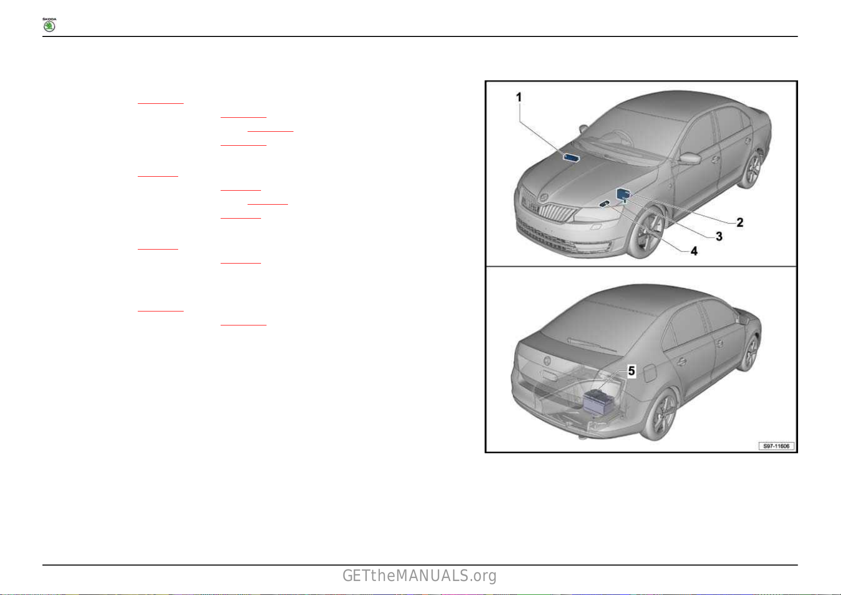
Fitting Locations
1 Fuses
1.1 Overview of the fuses (only for vehicles with left-hand drive)
1 - Fuse holder A -SA-
❑ Fitting location ⇒ page 3
❑ Fuse assignment as of May 2015 ⇒ page 3
2 - Fuse holder B -SB-
❑ Fitting location ⇒ page 4
❑ Fuse assignment as of May 2015 ⇒ page 5
❑ Fuse assignment as of November 2015 ⇒ page 7
❑ Fuse assignment as of May 2016 ⇒ page 8
3 - Fuse holder C -SC-
❑ Fitting location ⇒ page 9
❑ Fuse assignment as of May 2015 ⇒ page 11
❑ Fuse assignment as of November 2015 ⇒ page 14
❑ Fuse assignment as of May 2016 ⇒ page 17
4 - Jump start connection -TV32- anti-interference capacitor -C24-
5 - Fuse holder D -SD-
❑ Fitting location ⇒ page 20
❑ Fuse assignment as of May 2015 ⇒ page 21
No. 801 / 1
Ausgabe 05.2016
Page 2
RAPID NH
GETtheMANUALS.org
Fitting Locations
1.2 Overview of the fuses (only for vehicles with right-hand drive)
1 - Fuse holder C -SC-
❑ Fitting location ⇒ page 11
❑ Fuse assignment as of May 2015 ⇒ page 11
❑ Fuse assignment as of November 2015 ⇒ page 14
❑ Fuse assignment as of May 2016 ⇒ page 17
2 - Fuse holder B -SB-
❑ Fitting location ⇒ page 4
❑ Fuse assignment as of May 2015 ⇒ page 5
❑ Fuse assignment as of November 2015 ⇒ page 7
❑ Fuse assignment as of May 2016 ⇒ page 8
3 - Fuse holder A -SA-
❑ Fitting location ⇒ page 3
❑ Fuse assignment as of May 2015 ⇒ page 3
4 - Jump start connection -TV32- anti-interference capacitor -C24-
5 - Fuse holder D -SD-
❑ Fitting location ⇒ page 20
❑ Fuse assignment as of May 2015 ⇒ page 21
No. 801 / 2
Ausgabe 05.2016
Page 3

RAPID NH
GETtheMANUALS.org
1.3 Fitting location of the fuses (SA) at the E box
Fitting Locations
No. 801 / 3
1.3.1 Fuse assignment, as of May 2015
No.
1 - Fuse 1 on fuse holder A -SA1- 50A - Supply for terminal 75x 30a
2 - Fuse 2 on fuse holder A -SA2- 250A - Alternator with voltage regulator -CX1- 30a
Designation in the current flow diagram Nominal value
Functioncomponent Terminal
Ausgabe 05.2016
Page 4

RAPID NH
GETtheMANUALS.org
Fitting Locations
No. 801 / 4
No.
3 - Fuse 3 on fuse holder A -SA3- 80A - Power steering control unit -J500- (not valid for engine identification
4 - Fuse 4 on fuse holder A -SA4- 80A - Supply for terminal 30_2 (not valid for engine identification
5 - Fuse 5 on fuse holder A -SA5- Metal strips - Supply for terminal 30_1, 125A safety fuse 1 -S131- integrated in
Designation in the current flow diagram Nominal value
Functioncomponent Terminal
characters CXMA)
characters CXMA)
the wiring harness )not valid for engine identification characters
CXMA)
1.4 Fitting location of fuses (SB) on the E box, on left in engine compartment
30a
30a
30a
Ausgabe 05.2016
Page 5

RAPID NH
GETtheMANUALS.org
Fitting Locations
No. 801 / 5
The protection for the unlisted optional equipment can be found in the corresponding current flow diagrams.
1.4.1 Fuse assignment, as of May 2015
No.
Designation in the current flow diagram Nominal value
F1 - Fuse 1 on fuse holder B -SB1- 40A - Radiator fan control unit -J293- , Radiator fan -V7- (not valid for
Functioncomponent Terminal
engine identification characters CZCA, CXMA)
30a
Ausgabe 05.2016
Page 6

RAPID NH
GETtheMANUALS.org
Fitting Locations
No. 801 / 6
No.
F10 - Fuse 10 on fuse holder B -SB10- 25A - ABS control unit -J104- 30a
F11 - Fuse 11 on fuse holder B -SB11- - not assigned 87a
F12 - Fuse 12 on fuse holder B -SB12- 10A - Engine electronics 87a
F13 - Fuse 13 on fuse holder B -SB13- 7.5A - Brake pedal switch -F47- 87a
F14 - Fuse 14 on fuse holder B -SB14- 10A - Fuel pump relay -J17- , Pump for charge air cooler -V188- ,
F15 - Fuse 15 on fuse holder B -SB15- 7.5A - Engine control unit -J623- 50
F16 - Fuse 16 on fuse holder B -SB16- 30A - Starter -B- 50
F17 - Fuse 17 on fuse holder B -SB17- 20A - Engine control unit -J623- 87a
F18 - Fuse 18 on fuse holder B -SB18- 10A - Engine electronics, Low heat output relay -J359- , High heat output
F19 - Fuse 19 on fuse holder B -SB19- 15A - Lambda probe -G39- , Lambda probe after catalytic converter
F20 - Fuse 20 on fuse holder B -SB20- 7.5A - Automatic glow period control unit -J179- , heating resistor for
Designation in the current flow diagram Nominal value
50A Radiator fan control unit -J293- , Radiator fan -V7- Anti-
F2 - Fuse 2 on fuse holder B -SB2- 50A - Automatic glow period control unit -J179- 30a
F3 - Fuse 3 on fuse holder B -SB3- 40A - ABS control unit -J104- 30a
F4 - Fuse 4 on fuse holder B -SB4- 50A - Heater element for additional air heater -Z35F5 - Fuse 5 on fuse holder B -SB5- 50A - Heater element for additional air heater -Z35-
F6 - Fuse 6 on fuse holder B -SB6- 30A - Double clutch gearbox mechatronics -J743- , Automatic gearbox
F7 - Fuse 7 on fuse holder B -SB7- 7.5A - Engine control unit -J623- 30a
F8 - Fuse 8 on fuse holder B -SB8- 30A - Windscreen wiper motor -V- 30a
F9 - Fuse 9 on fuse holder B -SB9- 7.5A - Battery monitor control unit -J367- , Onboard control unit -J519- 30a
20A - Ignition system (for petrol engines)
Functioncomponent Terminal
interference capacitor -C24- (applies to engine identification
characters CZCA, CXMA)
control unit -J217-
Heating backup pump -V488- , Radiator fan control unit -J293- ,
engine electronics
relay -J360-
-G130-
crankcase ventilation -N79- (on diesel engines)
30a
87a
87a
87a
87a
Ausgabe 05.2016
Page 7

RAPID NH
GETtheMANUALS.org
1.4.2 Fuse assignment, as of November 2015
Fitting Locations
No. 801 / 7
No.
F10 - Fuse 10 on fuse holder B -SB10- 25A - ABS control unit -J104- 30a
F11 - Fuse 11 on fuse holder B -SB11- - not assigned 87a
F12 - Fuse 12 on fuse holder B -SB12- 10A - Engine electronics 87a
F13 - Fuse 13 on fuse holder B -SB13- 7.5A - Brake pedal switch -F47- 87a
F14 - Fuse 14 on fuse holder B -SB14- 10A - Fuel pump relay -J17- , Pump for charge air cooler -V188- ,
F15 - Fuse 15 on fuse holder B -SB15- 7.5A - Engine control unit -J623- 50
F16 - Fuse 16 on fuse holder B -SB16- 30A - Starter -B- 50
F17 - Fuse 17 on fuse holder B -SB17- 20A - Engine control unit -J623- 87a
F18 - Fuse 18 on fuse holder B -SB18- 10A - Engine electronics, Low heat output relay -J359- , High heat output
Designation in the current flow diagram Nominal value
F1 - Fuse 1 on fuse holder B -SB1- 40A - Radiator fan control unit -J293- , Radiator fan -V7- (not valid for
50A Radiator fan control unit -J293- , Radiator fan -V7- Anti-
F2 - Fuse 2 on fuse holder B -SB2- 50A - Automatic glow period control unit -J179- 30a
F3 - Fuse 3 on fuse holder B -SB3- 40A - ABS control unit -J104- 30a
F4 - Fuse 4 on fuse holder B -SB4- 50A - Heater element for additional air heater -Z35F5 - Fuse 5 on fuse holder B -SB5- 50A - Heater element for additional air heater -Z35-
F6 - Fuse 6 on fuse holder B -SB6- 30A - Double clutch gearbox mechatronics -J743- , Automatic gearbox
F7 - Fuse 7 on fuse holder B -SB7- 7.5A - Engine control unit -J623- 30a
F8 - Fuse 8 on fuse holder B -SB8- 30A - Windscreen wiper motor -V- 30a
F9 - Fuse 9 on fuse holder B -SB9- 7.5A - Battery monitor control unit -J367- , Onboard control unit -J519- 30a
F19 - Fuse 19 on fuse holder B -SB19- 15A - Lambda probe -G39- , Lambda probe after catalytic converter
F20 - Fuse 20 on fuse holder B -SB20- 7.5A - Automatic glow period control unit -J179- , heating resistor for
20A - Ignition system (for petrol engines)
Functioncomponent Terminal
engine identification characters CXMA)
interference capacitor -C24- (applies to engine identification
characters CXMA)
control unit -J217-
Heating backup pump -V488- , Radiator fan control unit -J293- ,
engine electronics
relay -J360-
-G130-
crankcase ventilation -N79- (on diesel engines)
30a
30a
87a
87a
87a
87a
Ausgabe 05.2016
Page 8

RAPID NH
GETtheMANUALS.org
1.4.3 Fuse assignment, as of May 2016
Fitting Locations
No. 801 / 8
No.
F10 - Fuse 10 on fuse holder B -SB10- 25A - ABS control unit -J104- 30a
F11 - Fuse 11 on fuse holder B -SB11- - not assigned 87a
F12 - Fuse 12 on fuse holder B -SB12- 10A - Engine electronics 87a
F13 - Fuse 13 on fuse holder B -SB13- 7.5A - Brake pedal switch -F47- 87a
F14 - Fuse 14 on fuse holder B -SB14- 10A - Fuel pump relay -J17- , Pump for charge air cooler -V188- ,
Designation in the current flow diagram Nominal value
F1 - Fuse 1 on fuse holder B -SB1- 40A - Radiator fan control unit -J293- , Radiator fan -V7- (not valid for
50A Radiator fan control unit -J293- , Radiator fan -V7- Anti-
F2 - Fuse 2 on fuse holder B -SB2- 50A - Automatic glow period control unit -J179- 30a
F3 - Fuse 3 on fuse holder B -SB3- 40A - ABS control unit -J104- 30a
F4 - Fuse 4 on fuse holder B -SB4- 50A - Heating element for additional air heating -Z35- (not for vehicles
30A - Heated windscreen -Z2-
F5 - Fuse 5 on fuse holder B -SB5- 50A - Heating element for additional air heating -Z35- (not for vehicles
30A - Heated windscreen -Z2-
F6 - Fuse 6 on fuse holder B -SB6- 30A - Double clutch gearbox mechatronics -J743- , Automatic gearbox
F7 - Fuse 7 on fuse holder B -SB7- 7.5A - Engine control unit -J623- 30a
F8 - Fuse 8 on fuse holder B -SB8- 30A - Windscreen wiper motor -V- 30a
F9 - Fuse 9 on fuse holder B -SB9- 7.5A - Battery monitor control unit -J367- , Onboard control unit -J519- 30a
F15 - Fuse 15 on fuse holder B -SB15- 7.5A - Engine control unit -J623- , voltage stabiliser -J532- 50
F16 - Fuse 16 on fuse holder B -SB16- 30A - Starter -B- 50
F17 - Fuse 17 on fuse holder B -SB17- 20A - Engine control unit -J623- 87a
F18 - Fuse 18 on fuse holder B -SB18- 10A - Engine electronics, Low heat output relay -J359-
Functioncomponent Terminal
engine identification characters CXMA)
interference capacitor
characters CXMA)
with Russia equipment)
with Russia equipment)
control unit -J217-
Heating backup pump
engine electronics
relay -J360-
-C24- (applies to engine identification
(only for vehicles with Russia equipment)
(only for vehicles with Russia equipment)
-V488- , Radiator fan control unit -J293- ,
, High heat output
30a
30a
87a
87a
Ausgabe 05.2016
Page 9

RAPID NH
GETtheMANUALS.org
Fitting Locations
No. 801 / 9
No.
F19 - Fuse 19 on fuse holder B -SB19- 15A - Lambda probe -G39- , Lambda probe after catalytic converter
F20 - Fuse 20 on fuse holder B -SB20- 7.5A - Automatic glow period control unit -J179- , heating resistor for
Fuse colours
50 A - red
40 A - orangegreen
30 A - greenpink
25 A - white
20 A - yellowblue
15 A - blue
10 A - red
7.5 A - brown
5 A - beige
Designation in the current flow diagram Nominal value
20A - Ignition system (for petrol engines)
Functioncomponent Terminal
-G130-
crankcase ventilation -N79- (on diesel engines)
1.5 Fitting location of the fuses (SC) below the left dash panel (only for vehicles with left-hand drive)
87a
87a
Ausgabe 05.2016
Page 10

RAPID NH
GETtheMANUALS.org
Fitting Locations
No. 801 / 10
The protection for the unlisted optional equipment can be found in the corresponding current flow diagrams.
Ausgabe 05.2016
Page 11

RAPID NH
GETtheMANUALS.org
Fitting Locations
1.6 Fitting location of the fuses (SC) below the right dash panel (only for vehicles with right-hand drive)
No. 801 / 11
The protection for the unlisted optional equipment can be found in the corresponding current flow diagrams.
1.6.1 Fuse assignment, as of May 2015
No.
Designation in the current flow diagram Nominal value
F1 - Fuse 1 on fuse holder C -SC1- 40A - Supply for left light 30a_1
Functioncomponent Terminal
Ausgabe 05.2016
Page 12

RAPID NH
GETtheMANUALS.org
Fitting Locations
No. 801 / 12
No.
F10 - Fuse 10 on fuse holder C -SC10- 25A - Window regulator motor, rear left -V26- 30a_1
F11 - Fuse 11 on fuse holder C -SC11- 30A - Headlight washer system relay -J39- 30a_1
F12 - Fuse 12 on fuse holder C -SC12- 7.5A - Multimedia system operating unit -E380- , Display unit for control
F13 - Fuse 13 on fuse holder C -SC13- - not assigned 30a_1
F14 - Fuse 14 on fuse holder C -SC14- 7.5A - Light switch -E1- , Headlight dipperflasher switch -E4- , Multifunction
F15 - Fuse 15 on fuse holder C -SC15- 7.5A - Tiptronic switch -F189- , Heater control unit -J65- , Air conditioning
F16 - Fuse 16 on fuse holder C -SC16- 7.5A - Dash panel insert -K- 30a_1
F17 - Fuse 17 on fuse holder C -SC17- 7.5A - Anti-theft alarm system horn -H8- , Sensor for anti-theft alarm
F18 - Fuse 18 on fuse holder C -SC18- - not assigned
F19 - Fuse 19 on fuse holder C -SC19F20 - Fuse 20 on fuse holder C -SC20F21 - Fuse 21 on fuse holder C -SC21F22 - Fuse 22 on fuse holder C -SC22- 7.5A - Windscreen and rear window washer pump -V59- 53c
F23 - Fuse 23 on fuse holder C -SC23- 20A - Heated front seat control unit -J774- 15a
F24 - Fuse 24 on fuse holder C -SC24- 30A - Fresh air blower switch -E9- , Fresh air blower -V2- , Fresh air blower
F25 - Fuse 25 on fuse holder C -SC25- - not assigned
F26 - Fuse 26 on fuse holder C -SC26- 7.5A - Heated driver seat regulator -E94- , Heated front passenger seat
F27 - Fuse 27 on fuse holder C -SC27- 15A - Rear window wiper motor -V12- 75x
Designation in the current flow diagram Nominal value
F2 - Fuse 2 on fuse holder C -SC2- 30A - Central locking 30a_1
F3 - Fuse 3 on fuse holder C -SC3- 30A - Supply for terminal 15 30a_1
F4 - Fuse 4 on fuse holder C -SC4- 40A - Supply for right light 30a_1
F5 - Fuse 5 on fuse holder C -SC5- 25A - Window regulator motor, driver side -V147- 30a_1
F6 - Fuse 6 on fuse holder C -SC6- 30A - Onboard control unit -J519- 30a_1
F7 - Fuse 7 on fuse holder C -SC7- 20A - High tone horn -H2- , Low tone horn -H7- 30a_1
F8 - Fuse 8 on fuse holder C -SC8- 25A - Trailer detector control unit -J345- 30a_1
F9 - Fuse 9 on fuse holder C -SC9- 10A - Ignition starter switch -D- Terminal 30 30a_1
Functioncomponent Terminal
unit of the display and operating unit, front information -J685-
steering wheel control unit -J453- , Ignition key withdrawal lock
solenoid -N376- , Control unit for wireless data transfer -J1070- , Air
humidity, rain and light detector sensor -G823- , Humidity sender
-G355- , mobile phone pre-installation
system control unit -J301- , Climatronic control unit -J255- , 16-pin
connector -T16b- , at diagnostic connection
system -G578-
- not assigned
- not assigned
- not assigned
control unit -J126-
regulator -E95-
30a_1
30a_1
30a_1
30a_1
75x
75x
Ausgabe 05.2016
Page 13

RAPID NH
GETtheMANUALS.org
Fitting Locations
No. 801 / 13
No.
F28 - Fuse 28 on fuse holder C -SC28F29 - Fuse 29 on fuse holder C -SC29- 10A - Airbag control unit -J234- (for vehicles with entry and start
F30 - Fuse 30 on fuse holder C -SC30- 7.5A - Light switch -E1- , Reversing light switch -F4- , TCS and ESP button
F31 - Fuse 31 on fuse holder C -SC31- 7.5A - Fuel pump control unit -J538- (for engine identification characters
F32 - Fuse 32 on fuse holder C -SC32- 7.5A - 16-pin connector -T16b- , at diagnostic connection, headlight range
F33 - Fuse 33 on fuse holder C -SC33- 7.5A - Starter relay 1 -J906- , starter relay 2 -J907- , clutch position sender
F34 - Fuse 34 on fuse holder C -SC34- 7.5A - Heater element for left spray jet -Z20- , Heater element for right
F35 - Fuse 35 on fuse holder C -SC35F36 - Fuse 36 on fuse holder C -SC36F37 - Fuse 37 on fuse holder C -SC37- 7.5A - Clearance control control unit -J428- 15a
F38 - Fuse 38 on fuse holder C -SC38F39 - Fuse 39 on fuse holder C -SC39- 50A - Low heat output relay -J359- 30a_2
F40 - Fuse 40 on fuse holder C -SC40F41 - Fuse 41 on fuse holder C -SC41- 30A - heated rear window -Z1- 30a_2
F42 - Fuse 42 on fuse holder C -SC42- 25A - Window regulator motor, front passenger side -V148- 30a_2
F43 - Fuse 43 on fuse holder C -SC43- 15A - Trailer detector control unit -J345- 30a_2
F44 - Fuse 44 on fuse holder C -SC44- 15A - Socket -U- , Cigarette lighter -U1- 30a_2
F45 - Fuse 45 on fuse holder C -SC45- 25A - Window regulator motor, rear right -V27- 30a_2
F46 - Fuse 46 on fuse holder C -SC46- 15A - Intermittent wiper switch -E22- , Rear wiper switch -E34- ,
F47 - Fuse 47 on fuse holder C -SC47- 15A - Trailer detector control unit -J345- 30a_2
F48 - Fuse 48 on fuse holder C -SC48- 25A - Trailer detector control unit -J345- 30a_2
Designation in the current flow diagram Nominal value
Functioncomponent Terminal
- not assigned 75x
authorisation)
-E256- , Front passenger side airbag deactivated warning lamp
-K145- , Heater control unit -J65- , High-pressure sender -G65- , Air
conditioning system control unit -J301- , Window regulator motor
driver's side -V147- , Window regulator front passenger side
-V148- , Window regulator motor, rear left -V26- , Window regulator
motor, rear right -V27- , Automatic anti-dazzle interior mirror -Y7- ,
Parking aid control unit -J446- , mobile phone pre-installation
CJZC, CJZD)
Cruise control system, Radiator fan control unit -J293- , Relay for
windscreen washer pump -J576-
control adjuster -E102- , headlight range control motor, left -V48- ,
headlight range control motor, right -V49- , headlight dipperflasher
switch -E4-
-G476-
spray jet -Z21-
- not assigned 15a
- not assigned 15a
- not assigned 30a_2
- not assigned 30a_2
Intermittent wiper control -E38-
15a
15a
15a
15a
15a
15a
30a_2
Ausgabe 05.2016
Page 14

RAPID NH
GETtheMANUALS.org
Fitting Locations
No. 801 / 14
No.
F49 - Fuse 49 on fuse holder C -SC49- 15A - Fuel pump control unit -J538- (valid for engine identification
F50 - Fuse 50 on fuse holder C -SC50- 20A - Control unit for IT 1 -J794- 30a_2
F51 - Fuse 51 on fuse holder C -SC51- 10A - Supply for mirror heating 30a_2
F52 - Fuse 52 on fuse holder C -SC52- 7.5A - Entry and start authorisation control unit -J518- 30a_2
F53 - Fuse 53 on fuse holder C -SC53- 10A - Electronic steering column lock control unit -J764- 30a_2
F54 - Fuse 54 on fuse holder C -SC54- 15A - ABS control unit -J104- 30a_2
F55 - Fuse 55 on fuse holder C -SC55F56 - Fuse 56 on fuse holder C -SC56F57 - Fuse 57 on fuse holder C -SC57F58 - Fuse 58 on fuse holder C -SC58F59 - Fuse 59 on fuse holder C -SC59-
Designation in the current flow diagram Nominal value
20A - Fuel system pressurisation pump -G6- (valid for engine identification
Functioncomponent Terminal
characters CJZC, CJZD, CZCA)
characters CWVA, CWVB, CUSB, CXMA)
- not assigned
- not assigned
- not assigned
- not assigned
- not assigned
30a_2
1.6.2 Fuse assignment, as of November 2015
No.
F10 - Fuse 10 on fuse holder C -SC10- 25A - Window regulator motor, rear left -V26- 30a_1
F11 - Fuse 11 on fuse holder C -SC11- 30A - Headlight washer system relay -J39- 30a_1
F12 - Fuse 12 on fuse holder C -SC12- 7.5A - Multimedia system operating unit -E380- , Display unit for control
F13 - Fuse 13 on fuse holder C -SC13- - not assigned 30a_1
Designation in the current flow diagram Nominal value
F1 - Fuse 1 on fuse holder C -SC1- 40A - Supply for left light 30a_1
F2 - Fuse 2 on fuse holder C -SC2- 30A - Central locking 30a_1
F3 - Fuse 3 on fuse holder C -SC3- 30A - Supply for terminal 15 30a_1
F4 - Fuse 4 on fuse holder C -SC4- 40A - Supply for right light 30a_1
F5 - Fuse 5 on fuse holder C -SC5- 25A - Window regulator motor, driver side -V147- 30a_1
F6 - Fuse 6 on fuse holder C -SC6- 30A - Onboard control unit -J519- 30a_1
F7 - Fuse 7 on fuse holder C -SC7- 20A - High tone horn -H2- , Low tone horn -H7- 30a_1
F8 - Fuse 8 on fuse holder C -SC8- 25A - Trailer detector control unit -J345- 30a_1
F9 - Fuse 9 on fuse holder C -SC9- 10A - Ignition starter switch -D- Terminal 30 30a_1
Functioncomponent Terminal
unit of the display and operating unit, front information
-J685-
30a_1
Ausgabe 05.2016
Page 15
RAPID NH
GETtheMANUALS.org
Fitting Locations
No. 801 / 15
No.
F14 - Fuse 14 on fuse holder C -SC14- 7.5A - Light switch -E1- , Headlight dipperflasher switch -E4- , Multifunction
F15 - Fuse 15 on fuse holder C -SC15- 7.5A - Tiptronic switch -F189- , Heater control unit -J65- , Air conditioning
F16 - Fuse 16 on fuse holder C -SC16- 7.5A - Dash panel insert -K- 30a_1
F17 - Fuse 17 on fuse holder C -SC17- 7.5A - Anti-theft alarm system horn -H8- , Sensor for anti-theft alarm
F18 - Fuse 18 on fuse holder C -SC18- - not assigned
F19 - Fuse 19 on fuse holder C -SC19F20 - Fuse 20 on fuse holder C -SC20F21 - Fuse 21 on fuse holder C -SC21F22 - Fuse 22 on fuse holder C -SC22- 7.5A - Windscreen and rear window washer pump -V59- 53c
F23 - Fuse 23 on fuse holder C -SC23- 20A - Heated front seat control unit -J774- 15a
F24 - Fuse 24 on fuse holder C -SC24- 30A - Fresh air blower switch -E9- , Fresh air blower -V2- , Fresh air blower
F25 - Fuse 25 on fuse holder C -SC25- - not assigned
F26 - Fuse 26 on fuse holder C -SC26- 7.5A - Heated driver seat regulator -E94- , Heated front passenger seat
F27 - Fuse 27 on fuse holder C -SC27- 15A - Rear window wiper motor -V12- 75x
F28 - Fuse 28 on fuse holder C -SC28F29 - Fuse 29 on fuse holder C -SC29- 10A - Airbag control unit -J234- 15a
F30 - Fuse 30 on fuse holder C -SC30- 7.5A - Light switch -E1- , Reversing light switch -F4- , TCS and ESP button
Designation in the current flow diagram Nominal value
F31 - Fuse 31 on fuse holder C -SC31- 7.5A - Fuel pump control unit -J538- (for engine identification characters
Functioncomponent Terminal
steering wheel control unit -J453- , Ignition key withdrawal lock
solenoid -N376- , Control unit for wireless data transfer -J1070- , Air
humidity, rain and light detector sensor -G823- , Humidity sender
-G355-
system control unit -J301- , Climatronic control unit -J255- , 16-pin
connector -T16b- , at diagnostic connection
system -G578-
- not assigned
- not assigned
- not assigned
control unit -J126-
regulator -E95-
- not assigned 75x
-E256- , Front passenger side airbag deactivated warning lamp
-K145- , Heater control unit -J65- , High-pressure sender -G65- , Air
conditioning system control unit -J301- , Window regulator motor
driver's side -V147- , Window regulator front passenger side
-V148- , Window regulator motor, rear left -V26- , Window regulator
motor, rear right -V27- , Automatic anti-dazzle interior mirror -Y7- ,
Parking aid control unit -J446-
CJZC, CJZD)
Cruise control system, Radiator fan control unit -J293- , Relay for
windscreen washer pump -J576-
30a_1
30a_1
30a_1
75x
75x
15a
15a
Ausgabe 05.2016
Page 16

RAPID NH
GETtheMANUALS.org
Fitting Locations
No. 801 / 16
No.
F32 - Fuse 32 on fuse holder C -SC32- 7.5A - 16-pin connector -T16b- , at diagnostic connection, headlight range
F33 - Fuse 33 on fuse holder C -SC33- 7.5A - Starter relay 1 -J906- , starter relay 2 -J907- , clutch position sender
F34 - Fuse 34 on fuse holder C -SC34- 7.5A - Heater element for left spray jet -Z20- , Heater element for right
F35 - Fuse 35 on fuse holder C -SC35F36 - Fuse 36 on fuse holder C -SC36F37 - Fuse 37 on fuse holder C -SC37- 7.5A - Clearance control control unit -J428- 15a
F38 - Fuse 38 on fuse holder C -SC38F39 - Fuse 39 on fuse holder C -SC39- 50A - Low heat output relay -J359- 30a_2
F40 - Fuse 40 on fuse holder C -SC40F41 - Fuse 41 on fuse holder C -SC41- 30A - heated rear window -Z1- 30a_2
F42 - Fuse 42 on fuse holder C -SC42- 25A - Window regulator motor, front passenger side -V148- 30a_2
F43 - Fuse 43 on fuse holder C -SC43- 15A - Trailer detector control unit -J345- 30a_2
F44 - Fuse 44 on fuse holder C -SC44- 15A - Socket -U- , Cigarette lighter -U1- 30a_2
F45 - Fuse 45 on fuse holder C -SC45- 25A - Window regulator motor, rear right -V27- 30a_2
F46 - Fuse 46 on fuse holder C -SC46- 15A - Intermittent wiper switch -E22- , Rear wiper switch -E34- ,
F47 - Fuse 47 on fuse holder C -SC47- 15A - Trailer detector control unit -J345- 30a_2
F48 - Fuse 48 on fuse holder C -SC48- 25A - Trailer detector control unit -J345- 30a_2
F49 - Fuse 49 on fuse holder C -SC49- 15A - Fuel pump control unit -J538- (valid for engine identification
F50 - Fuse 50 on fuse holder C -SC50- 20A - Control unit for IT 1 -J794- 30a_2
F51 - Fuse 51 on fuse holder C -SC51- 10A - Supply for mirror heating 30a_2
F52 - Fuse 52 on fuse holder C -SC52- 7.5A - Entry and start authorisation control unit -J518- 30a_2
F53 - Fuse 53 on fuse holder C -SC53- 10A - Electronic steering column lock control unit -J764- 30a_2
F54 - Fuse 54 on fuse holder C -SC54- 15A - ABS control unit -J104- 30a_2
F55 - Fuse 55 on fuse holder C -SC55F56 - Fuse 56 on fuse holder C -SC56F57 - Fuse 57 on fuse holder C -SC57-
Designation in the current flow diagram Nominal value
20A - Fuel system pressurisation pump -G6- (valid for engine identification
Functioncomponent Terminal
control adjuster -E102- , headlight range control motor, left -V48- ,
headlight range control motor, right -V49- , headlight dipperflasher
switch -E4-
-G476-
spray jet -Z21-
- not assigned 15a
- not assigned 15a
- not assigned 30a_2
- not assigned 30a_2
Intermittent wiper control -E38-
characters CJZC, CJZD, CZCA)
characters CWVA, CWVB, CUSB, CXMA)
- not assigned
- not assigned
- not assigned
15a
15a
15a
30a_2
30a_2
Ausgabe 05.2016
Page 17

RAPID NH
GETtheMANUALS.org
Fitting Locations
No. 801 / 17
No.
F58 - Fuse 58 on fuse holder C -SC58F59 - Fuse 59 on fuse holder C -SC59-
Designation in the current flow diagram Nominal value
Functioncomponent Terminal
- not assigned
- not assigned
1.6.3 Fuse assignment, as of May 2016
No.
F10 - Fuse 10 on fuse holder C -SC10- 25A - Window regulator motor, rear left -V26- 30a_1
F11 - Fuse 11 on fuse holder C -SC11- 30A - Headlight washer system relay -J39- 30a_1
F12 - Fuse 12 on fuse holder C -SC12- 7.5A - Multimedia system operating unit -E380- , Display unit for control
F13 - Fuse 13 on fuse holder C -SC13- 20A - Voltage stabiliser -J532- (only for vehicles with Taxi equipment) 30a_1
F14 - Fuse 14 on fuse holder C -SC14- 7.5A - Light switch -E1-
F15 - Fuse 15 on fuse holder C -SC15- 7.5A - Tiptronic switch -F189- , Heater control unit -J65- , Air conditioning
Designation in the current flow diagram Nominal value
F1 - Fuse 1 on fuse holder C -SC1- 40A - Supply for left light 30a_1
F2 - Fuse 2 on fuse holder C -SC2- 30A - Central locking, windscreen and rear window washer pump -V59- ,
F3 - Fuse 3 on fuse holder C -SC3- 30A - Supply for terminal 15 30a_1
F4 - Fuse 4 on fuse holder C -SC4- 40A - Supply for right light 30a_1
F5 - Fuse 5 on fuse holder C -SC5- 25A - Window regulator motor, driver side -V147- 30a_1
F6 - Fuse 6 on fuse holder C -SC6- 30A - Onboard control unit -J519- 30a_1
F7 - Fuse 7 on fuse holder C -SC7- 20A - High tone horn -H2- , Low tone horn -H7- 30a_1
F8 - Fuse 8 on fuse holder C -SC8- 25A - Trailer detector control unit -J345- 30a_1
F9 - Fuse 9 on fuse holder C -SC9- 10A - Ignition starter switch -D- Terminal 30 30a_1
F16 - Fuse 16 on fuse holder C -SC16- 7.5A - Dash panel insert -K- 30a_1
F17 - Fuse 17 on fuse holder C -SC17- 7.5A - Anti-theft alarm system horn -H8- , Sensor for anti-theft alarm
F18 - Fuse 18 on fuse holder C -SC18- 10A - Heated rear seat control unit -J786- 15a
F19 - Fuse 19 on fuse holder C -SC19F20 - Fuse 20 on fuse holder C -SC20-
Functioncomponent Terminal
rear window wiper motor
unit of the display and operating unit, front information
, Headlight dipperflasher switch -E4- , Multifunction
steering wheel control unit -J453- , Ignition key withdrawal lock
solenoid -N376- , Control unit for wireless data transfer -J1070- , Air
humidity, rain and light detector sensor -G823- , Humidity sender
-G355- , rear view camera -R189-
system control unit -J301- , Climatronic control unit
connector -T16b- , at diagnostic connection, Heated windscreen
relay -J47-
system -G578-
- not assigned
- not assigned
-V12-
-J685-
-J255- , 16-pin
30a_1
30a_1
30a_1
30a_1
30a_1
Ausgabe 05.2016
Page 18

RAPID NH
GETtheMANUALS.org
Fitting Locations
No. 801 / 18
No.
F21 - Fuse 21 on fuse holder C -SC21F22 - Fuse 22 on fuse holder C -SC22- 10A - Windscreen and rear window washer pump -V59- (for vehicles
F23 - Fuse 23 on fuse holder C -SC23- 20A - Heated front seat control unit -J774- 15a
F24 - Fuse 24 on fuse holder C -SC24- 30A - Fresh air blower switch -E9- , Fresh air blower -V2- , Fresh air blower
F25 - Fuse 25 on fuse holder C -SC25- - not assigned
F26 - Fuse 26 on fuse holder C -SC26- 7.5A - Heated driver seat regulator -E94- , Heated front passenger seat
F27 - Fuse 27 on fuse holder C -SC27- 15A - Rear window wiper motor -V12- 75x
F28 - Fuse 28 on fuse holder C -SC28F29 - Fuse 29 on fuse holder C -SC29- 10A - Airbag control unit -J234- 15a
F30 - Fuse 30 on fuse holder C -SC30- 7.5A - Reversing light switch -F4- , TCS and ESP button -E256- , Front
F31 - Fuse 31 on fuse holder C -SC31- 7.5A - Fuel pump control unit -J538- (for engine identification characters
F32 - Fuse 32 on fuse holder C -SC32- 7.5A - 16-pin connector -T16b- , at diagnostic connection , headlight range
F33 - Fuse 33 on fuse holder C -SC33- 7.5A - Starter relay 1 -J906- , starter relay 2 -J907- , clutch position sender
F34 - Fuse 34 on fuse holder C -SC34- 7.5A - Heater element for left spray jet -Z20- , Heater element for right
Designation in the current flow diagram Nominal value
F35 - Fuse 35 on fuse holder C -SC35F36 - Fuse 36 on fuse holder C -SC36F37 - Fuse 37 on fuse holder C -SC37- 7.5A - Clearance control control unit -J428- 15a
F38 - Fuse 38 on fuse holder C -SC38F39 - Fuse 39 on fuse holder C -SC39- 50A - Low heat output relay -J359- 30a_2
Functioncomponent Terminal
- not assigned
without entry and start authorisation and without heated windscreen)
control unit -J126-
regulator -E95- , Rear left heated seat switch -E77- , Rear right
heated seat switch -E78-
- not assigned 75x
passenger side airbag deactivated warning lamp -K145- , Heater
control unit -J65- , High-pressure sender -G65- , Air conditioning
system control unit -J301- , Window regulator motor, driver side
-V147- , Window regulator motor, front passenger side -V148- ,
Window regulator motor, rear left -V26- , Window regulator motor,
rear right -V27- , Automatic anti-dazzle interior mirror -Y7- , Parking
aid control unit -J446-
CJZC, CJZD)
Cruise control system, control unit for radiator fan -J293- , Relay for
windscreen washer pump -J576- , Light switch -E1-
control adjuster -E102- , headlight range control motor, left -V48- ,
headlight range control motor, right -V49- , headlight dipperflasher
switch -E4- , voltage stabiliser -J532-
-G476-
spray jet -Z21-
- not assigned 15a
- not assigned 15a
- not assigned 30a_2
53c
75x
75x
15a
15a
15a
15a
15a
Ausgabe 05.2016
Page 19

RAPID NH
GETtheMANUALS.org
Fitting Locations
No. 801 / 19
No.
F40 - Fuse 40 on fuse holder C -SC40F41 - Fuse 41 on fuse holder C -SC41- 30A - heated rear window -Z1- 30a_2
F42 - Fuse 42 on fuse holder C -SC42- 25A - Window regulator motor, front passenger side -V148- 30a_2
F43 - Fuse 43 on fuse holder C -SC43- 15A - Trailer detector control unit -J345- 30a_2
F44 - Fuse 44 on fuse holder C -SC44- 15A - Socket -U- , Socket -U- , Cigarette lighter -U1- (only for vehicles
F45 - Fuse 45 on fuse holder C -SC45- 25A - Window regulator motor, rear right -V27- 30a_2
F46 - Fuse 46 on fuse holder C -SC46- 15A - Intermittent wiper switch -E22- , Rear wiper switch -E34- ,
F47 - Fuse 47 on fuse holder C -SC47- 15A - Trailer detector control unit -J345- 30a_2
F48 - Fuse 48 on fuse holder C -SC48- 25A - Trailer detector control unit -J345- 30a_2
F49 - Fuse 49 on fuse holder C -SC49- 15A - Fuel pump control unit -J538- (valid for engine identification
F50 - Fuse 50 on fuse holder C -SC50- 20A - Control unit for IT 1 -J794- 30a_2
F51 - Fuse 51 on fuse holder C -SC51- 10A - Supply for mirror heating 30a_2
F52 - Fuse 52 on fuse holder C -SC52- 7.5A - Entry and start authorisation control unit -J518- 30a_2
F53 - Fuse 53 on fuse holder C -SC53- 10A - Electronic steering column lock control unit -J764- 30a_2
F54 - Fuse 54 on fuse holder C -SC54- 15A - ABS control unit -J104- 30a_2
F55 - Fuse 55 on fuse holder C -SC55F56 - Fuse 56 on fuse holder C -SC56F57 - Fuse 57 on fuse holder C -SC57F58 - Fuse 58 on fuse holder C -SC58- 10A - Heated rear seat control unit -J786- 15a
F59 - Fuse 59 on fuse holder C -SC59-
Designation in the current flow diagram Nominal value
20A - Cigarette lighter -U1- , 12 V socket -U5- (only for vehicles with 12 V
20A - Fuel system pressurisation pump -G6- (valid for engine identification
Functioncomponent Terminal
- not assigned 30a_2
without 12 V socket in luggage compartment)
socket in luggage compartment)
Intermittent wiper control -E38-
characters CJZC, CJZD, CZCA)
characters CWVA, CWVB, CUSB, CXMA)
- not assigned
- not assigned
- not assigned
- not assigned
30a_2
30a_2
30a_2
Fuse colours
50 A - red
40 A - orangegreen
30 A - greenpink
25 A - white
Ausgabe 05.2016
Page 20

RAPID NH
GETtheMANUALS.org
20 A - yellowblue
15 A - blue
10 A - red
7.5 A - brown
5 A - beige
Fitting Locations
1.7 Fitting location of the fuses (SD) on the battery in the luggage compartment
No. 801 / 20
Ausgabe 05.2016
Page 21

RAPID NH
GETtheMANUALS.org
1.7.1 Fuse assignment
Fitting Locations
No. 801 / 21
No.
1 - Fuse 1 on fuse holder D -SD1- 110A - Voltage supply of the fuses (SC)
2 - Fuse 2 on fuse holder D -SD2- 110A - Voltage supply of the fuses (SC)
3 - Fuse 3 on fuse holder D -SD3- 80A - Power steering control unit -J5004 - Ignition device for battery interruption -N253-
Designation in the current flow diagram Nominal value
Functioncomponent Terminal
Ausgabe 05.2016
Page 22

RAPID NH
GETtheMANUALS.org
Fitting Locations
1 Relay
1.1 Overview of the relay carriers (only for vehicles with left-hand drive)
1 - Relay carrier in the E box
❑ in engine compartment, left
❑ Relay position assignment ⇒ page 4
2 - Relay carrier on the E box
❑ in engine compartment, left
❑ Relay position assignment ⇒ page 3
3 - Relay carrier at the vehicle voltage control unit holder
❑ at the vehicle voltage control unit holder
❑ Relay position assignment ⇒ page 5
No. 802 / 1
Ausgabe 05.2016
Page 23

RAPID NH
GETtheMANUALS.org
Fitting Locations
1.2 Overview of the relay carriers (only for vehicles with right-hand drive)
1 - Relay carrier at the vehicle voltage control unit holder
❑ at the vehicle voltage control unit holder
❑ Relay position assignment ⇒ page 6
2 - Relay carrier on the E box
❑ in engine compartment, left
❑ Relay position assignment ⇒ page 3
3 - Relay carrier in the E box
❑ in engine compartment, left
❑ Relay position assignment ⇒ page 4
No. 802 / 2
Ausgabe 05.2016
Page 24

RAPID NH
GETtheMANUALS.org
Fitting Locations
1.3 Relay position assignment in the relay carrier on the E box
No. 802 / 3
R1 -
High heat output relay -J360- (not for vehicles with Russia equipment)
Heated windscreen relay -J47- (only for vehicles with Russia equipment)
Ausgabe 05.2016
Page 25

RAPID NH
GETtheMANUALS.org
Fitting Locations
1.4 Relay position assignment in the relay carrier in the E box
No. 802 / 4
R2 R3 R4 -
Starter relay 1 -J906Starter relay 2 -J907Main relay -J271-
Ausgabe 05.2016
Page 26

RAPID NH
GETtheMANUALS.org
1.5 Relay position assignment in the relay carrier below the left dash panel (only for vehicles with left-hand drive)
Fitting Locations
No. 802 / 5
Ausgabe 05.2016
Page 27

RAPID NH
GETtheMANUALS.org
Fitting Locations
No. 802 / 6
1.6 Relay position assignment in the relay carrier below the right dash panel (only for vehicles with right-hand drive)
1 - 1a
2 3 4 -
- 1b
Windscreen washer pump relay -J576- (for vehicles without entry and start authorisation and without heated windscreen)
Fuel pump relay -J17Terminal 15 voltage supply relay -J329X contact relief relay -J59not assigned
Ausgabe 05.2016
Page 28

RAPID NH
GETtheMANUALS.org
Fitting Locations
No. 802 / 7
5 6 7 8 9 10 11 12 -
Low heat output relay -J359Headlight washer system relay -J39not assigned
not assigned
not assigned
not assigned
not assigned
not assigned
Ausgabe 05.2016
Page 29

RAPID NH
GETtheMANUALS.org
Fitting Locations
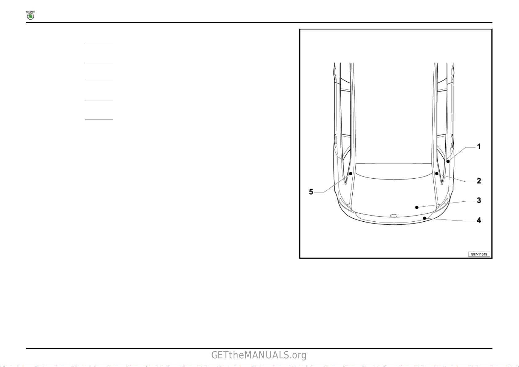
1 Earth points
1.1 Overview of earth points in the front part of the vehicle (only for vehicles with left-hand drive)
1 - Earth point 1 on front right of longitudinal member -685-
❑ Fitting location ⇒ page 4
2 - Earth point for gearbox and engine earth -652-
❑ Fitting location ⇒ page 4
3 - Earth point on cylinder head -15-
❑ Fitting location ⇒ page 4
4 - Earth point 2 on right A-pillar -751-
❑ Fitting location ⇒ page 4
5 - Earth point on right A-pillar -638-
❑ Fitting location ⇒ page 5
6 - Earth point at centre front roof -689-
❑ Fitting location ⇒ page 6
7 - Earth point 1 on the middle tunnel -687-
❑ Fitting location ⇒ page 6
8 - Earth point on top end of steering column -605-
❑ Fitting location ⇒ page 5
9 - Earth point on left A-pillar -639-
❑ Fitting location ⇒ page 5
10 - Earth point 2 on left in engine compartment -640-
❑ Fitting location ⇒ page 3
No. 803 / 1
11 - Earth point on left in engine compartment -12-
❑ Fitting location ⇒ page 3
12 - Earth strap, battery - body -1-
not valid for engine identification characters CXMA
❑ Fitting location ⇒ page 3
13 - Earth point 1 on front left of longitudinal member -671-
❑ Fitting location ⇒ page 3
Ausgabe 05.2016
Page 30

RAPID NH
GETtheMANUALS.org
Fitting Locations
1.2 Overview of earth points in the front part of the vehicle (only for vehicles with right-hand drive)
1 - Earth point 1 on front right of longitudinal member -685-
❑ Fitting location ⇒ page 4
2 - Earth point for gearbox and engine earth -652-
❑ Fitting location ⇒ page 4
3 - Earth point on cylinder head -15-
❑ Fitting location ⇒ page 4
4 - Earth point 2 on right A-pillar -751-
❑ Fitting location ⇒ page 4
5 - Earth point on right A-pillar -638-
❑ Fitting location ⇒ page 5
6 - Earth point at centre front roof -689-
❑ Fitting location ⇒ page 6
7 - Earth point on top end of steering column -605-
❑ Fitting location ⇒ page 5
8 - Earth point on left A-pillar -639-
❑ Fitting location ⇒ page 5
9 - Earth point 1 on the middle tunnel -687-
❑ Fitting location ⇒ page 6
10 - Earth point 2 on left in engine compartment -640-
❑ Fitting location ⇒ page 3
11 - Earth point on left in engine compartment -12-
❑ Fitting location ⇒ page 3
No. 803 / 2
12 - Earth strap, battery - body -1-
not valid for engine identification characters CXMA
❑ Fitting location ⇒ page 3
13 - Earth point 1 on front left of longitudinal member -671-
❑ Fitting location ⇒ page 3
Ausgabe 05.2016
Page 31

RAPID NH
GETtheMANUALS.org
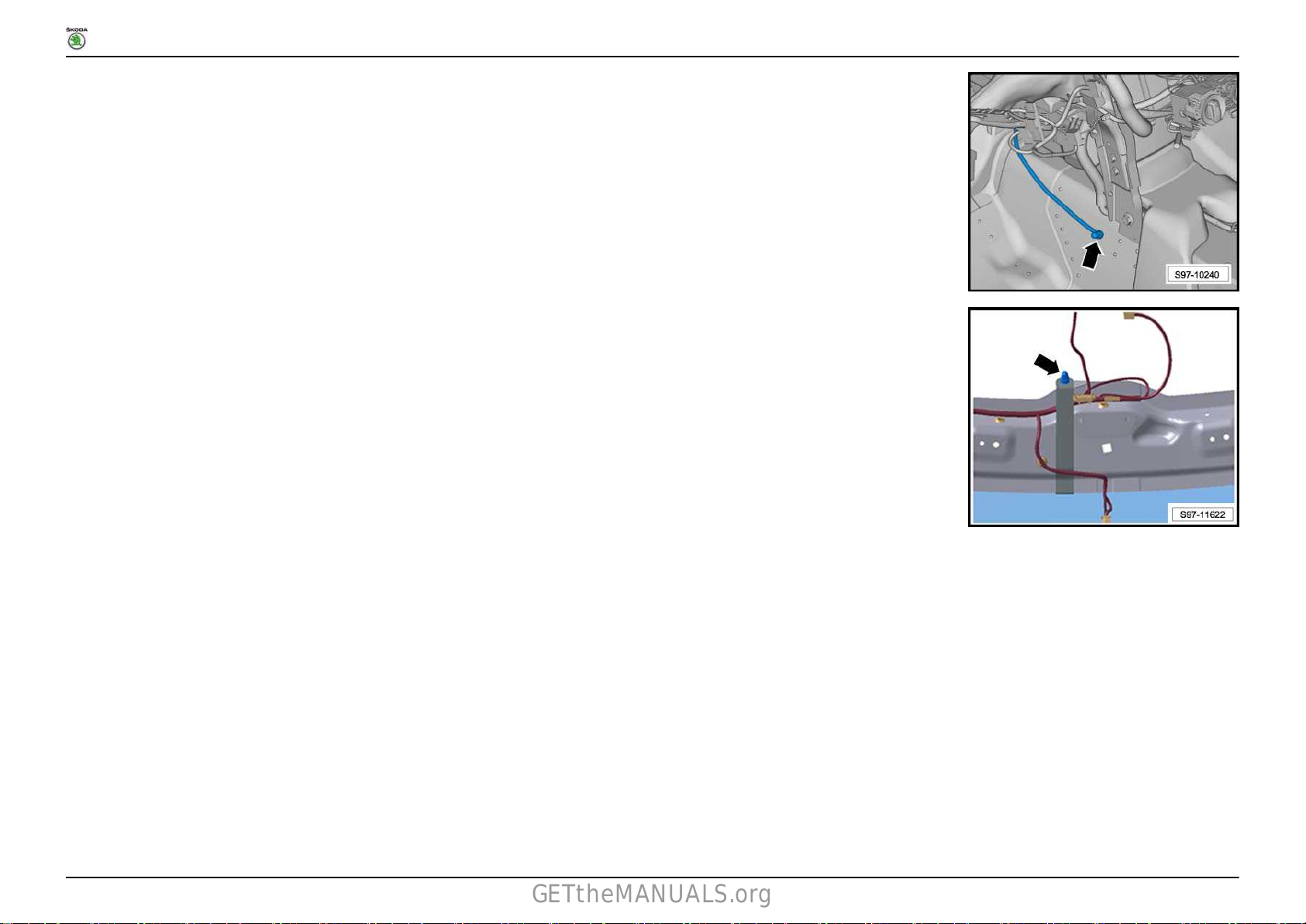
671 - Earth point 1 on front left of longitudinal member -arrow-
Tightening torque 9 Nm
Negative terminal of battery -arrow A-
Tightening torque 6 Nm
1 - Earth strap, battery - body -arrow B- (not valid for engine
identification characters CXMA)
Tightening torque 20 Nm
Fitting Locations
No. 803 / 3
12 - Earth point on left in engine compartment -arrow B-
Tightening torque 9 Nm
640 - Earth point 2 on left in engine compartment -arrow A-
Tightening torque 9 Nm
Ausgabe 05.2016
Page 32

RAPID NH
GETtheMANUALS.org
15 - Earth point on cylinder head -arrow-
Tightening torque 9 Nm
652 - Earth point for gearbox and engine earth -arrow A-
Tightening torque 20 Nm
685 - Earth point 1 on front right of longitudinal member -arrow B-
Tightening torque 20 Nm
Fitting Locations
No. 803 / 4
751 - Earth point 2 on right A-pillar -arrow B-
Tightening torque 9 Nm
Ausgabe 05.2016
Page 33

RAPID NH
GETtheMANUALS.org
638 - Earth point on right A-pillar -arrow A-
Tightening torque 9 Nm
639 - Earth point on left A-pillar -arrow-
Tightening torque 9 Nm
Fitting Locations
No. 803 / 5
605 - Earth point on top end of steering column -arrow-
Tightening torque 4 Nm
Ausgabe 05.2016
Page 34
RAPID NH
GETtheMANUALS.org
687 - Earth point 1 on the middle tunnel -arrow-
Tightening torque 9 Nm
689 - Earth point at centre front roof -arrow-
Tightening torque 9 Nm
Fitting Locations
No. 803 / 6
1.3 Overview of earth points in the rear part of the vehicle (Rapid NH)
Ausgabe 05.2016
Page 35

RAPID NH
GETtheMANUALS.org
1 - Earth point in luggage compartment, right -51-
❑ Fitting location ⇒ page 8
2 - Earth strap, battery - body -1-
applies to engine identification characters CXMA
❑ Fitting location ⇒ page 8
3 - Earth point, in rear lid, right -53-
❑ Fitting location ⇒ page 8
4 - Earth point in luggage compartment, left -50-
❑ Fitting location ⇒ page 9
Fitting Locations
No. 803 / 7
Ausgabe 05.2016
Page 36

RAPID NH
GETtheMANUALS.org
51 - Earth point in luggage compartment, right -arrow-
Tightening torque 9 Nm
Negative terminal of battery -arrow A-
Tightening torque 6 Nm
1 - Earth strap, battery - body -arrow B- (applies to engine
identification characters CXMA)
Tightening torque 20 Nm
Fitting Locations
No. 803 / 8
53 - Earth point, in rear lid, right -arrow-
Tightening torque 2 Nm
Ausgabe 05.2016
Page 37

RAPID NH
GETtheMANUALS.org
50 - Earth point in luggage compartment, left -arrow-
Tightening torque 9 Nm
Fitting Locations
1.4 Overview of earth points in the rear part of the vehicle (Rapid NH Spaceback)
No. 803 / 9
Ausgabe 05.2016
Page 38
RAPID NH
GETtheMANUALS.org
1 - Earth point in luggage compartment, right -51-
❑ Fitting location ⇒ page 11
2 - Earth point on right D-pillar -654-
❑ Fitting location ⇒ page 11
3 - Earth strap, battery - body -1-
❑ Fitting location ⇒ page 11
4 - Earth point, in rear lid, right -53-
❑ Fitting location ⇒ page 12
5 - Earth point on left D-pillar -653-
❑ Fitting location ⇒ page 12
Fitting Locations
No. 803 / 10
Ausgabe 05.2016
Page 39

RAPID NH
GETtheMANUALS.org
51 - Earth point in luggage compartment, right -arrow-
Tightening torque 9 Nm
654 - Earth point on right D-pillar -arrow-
Tightening torque 9 Nm
Fitting Locations
No. 803 / 11
Negative terminal of battery -arrow A-
Tightening torque 6 Nm
1 - Earth strap, battery - body -arrow B-
Tightening torque 20 Nm
Ausgabe 05.2016
Page 40

RAPID NH
GETtheMANUALS.org
53 - Earth point, in rear lid, right -arrow-
Tightening torque 2 Nm
653 - Earth point on left D-pillar -arrow-
Tightening torque 9 Nm
Fitting Locations
No. 803 / 12
Ausgabe 05.2016
Page 41
RAPID NH
GETtheMANUALS.org
Fitting Locations
No. 804 / 1
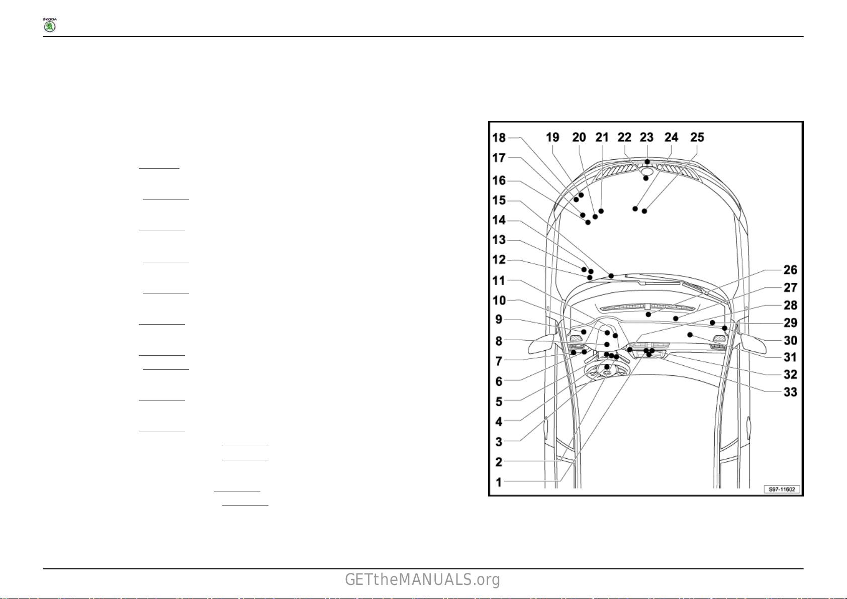
1 Control units in the front part of the vehicle
1.1 Overview of the control units (only for vehicles with left-hand drive)
1 - Display unit for control unit of the display and operating unit, front information -J685- Multimedia
system operating unit -E380-
❑ for MIB Standard
❑ Fitting location ⇒ page 7
2 - Ignition starter switch -D-
❑ Pin assignment ⇒ page 13
3 - Multi-function steering wheel control unit -J453-
❑ Fitting location ⇒ page 14
4 - Coil -F350-
❑ Pin assignment ⇒ page 14
5 - Steering column combination switch -E595-
❑ Pin assignment ⇒ page 16
6 - Headlight range control adjuster -E102-
❑ Fitting location ⇒ page 17
7 - Light switch -E1-
❑ Fitting location ⇒ page 18
❑ Pin assignment ⇒ page 18
8 - Electronic steering column lock control unit -J764-
❑ Fitting location ⇒ page 20
9 - Onboard control unit -J519- Data bus diagnostic interface -J533-
❑ Fitting location ⇒ page 25
❑ Fuse assignment as of May 2015 ⇒ page 26
❑ Fuse assignment as of May 2016 ⇒ page 33
10 - Control unit in dash panel insert -J285- Immobilizer control unit -J362-
❑ Pin assignment as of May 2015 ⇒ page 22
❑ Fuse assignment as of May 2016 ⇒ page 23
11 - Power steering control unit -J500-
❑ electromechanical power steering
Ausgabe 05.2016
Page 42

RAPID NH
GETtheMANUALS.org
❑ Fitting location ⇒ page 46
12 - Engine control unit -J623-
❑ Fitting location ⇒ page 40
13 - Automatic gearbox control unit -J217-
❑ Fitting location ⇒ page 42
14 - Windscreen wiper motor -V-
❑ Fitting location ⇒ page 43
❑ Pin assignment ⇒ page 43
15 - ABS control unit -J104-
❑ Fitting location ⇒ page 55
16 - Battery monitor control unit -J367-
❑ Fitting location ⇒ page 45
17 - Radiator fan control unit -J293-
❑ Fitting location (not valid for engine identification characters CXMA) ⇒ page 47
❑ Pin assignment (not valid for engine identification characters CXMA) ⇒ page 47
18 - Low tone horn -H7-
❑ Fitting location ⇒ page 50
19 - High tone horn -H2-
❑ Fitting location ⇒ page 50
20 - Automatic glow period control unit -J179-
❑ Fitting location ⇒ page 51
21 - Double clutch gearbox mechatronics -J743-
❑ Fitting location ⇒ page 51
❑ Pin assignment ⇒ page 52
22 - Radiator fan control unit -J293-
❑ Pin assignment (applies to engine identification characters CXMA) ⇒ page 49
23 - Control unit for clearance control -J428-
❑ Fitting location ⇒ page 8
24 - Lambda probe after catalytic converter -G130-
❑ Fitting location ⇒ page 52
❑ Pin assignment ⇒ page 53
25 - Lambda probe -G39-
❑ Fitting location ⇒ page 54
Fitting Locations
No. 804 / 2
Ausgabe 05.2016
Page 43
RAPID NH
GETtheMANUALS.org
❑ Pin assignment ⇒ page 54
26 - Airbag control unit -J234-
❑ Fitting location ⇒ page 57
❑ Pin assignment ⇒ page 57
27 - Fresh air blower control unit -J126-
28 - Heated front seat control unit -J774-
❑ Fitting location ⇒ page 59
29 - Control unit for cornering light and headlight range control -J745-
❑ Fitting location ⇒ page 11
30 - Entry and start authorisation control unit - J518-
❑ Fitting location ⇒ page 9
31 - Control unit for IT 1 -J794-
❑ for MIB Standard
32 - Heater control unit -J65- Air conditioning system control unit -J301- Climatronic control unit -J255-
❑ Pin assignment Heater control unit -J65- ⇒ page 59
❑ Pin assignment Air conditioning system control unit -J301- ⇒ page 61
❑ Pin assignment Climatronic control unit -J255- ⇒ page 62
33 - Control unit for IT 1 -J794- Display unit for control unit of the display and operating unit, front information -J685-
❑ for MIB Basic, Entry
Fitting Locations
No. 804 / 3
Ausgabe 05.2016
Page 44

RAPID NH
GETtheMANUALS.org
Fitting Locations
1.2 Overview of the control units (only for vehicles with right-hand drive)
1 - Heater control unit -J65- Air conditioning system control unit -J301- Climatronic control unit -J255-
❑ Pin assignment Heater control unit -J65- ⇒ page 59
❑ Pin assignment Air conditioning system control unit -J301- ⇒ page 61
❑ Pin assignment Climatronic control unit -J255- ⇒ page 62
2 - Display unit for control unit of the display and operating unit, front information -J685- Multimedia
system operating unit -E380-
❑ for MIB Standard
❑ Fitting location ⇒ page 7
3 - Control unit for IT 1 -J794-
❑ for MIB Standard
4 - Fresh air blower control unit -J126-
5 - Control unit for cornering light and headlight range control -J745-
❑ Fitting location ⇒ page 12
6 - Entry and start authorisation control unit - J518-
❑ Fitting location ⇒ page 10
7 - ABS control unit -J104-
❑ Fitting location ⇒ page 55
8 - Engine control unit -J623-
❑ Fitting location ⇒ page 40
9 - Automatic gearbox control unit -J217-
❑ Fitting location ⇒ page 42
10 - Battery monitor control unit -J367-
❑ Fitting location ⇒ page 45
No. 804 / 4
11 - Radiator fan control unit -J293-
❑ Fitting location (not valid for engine identification characters CXMA) ⇒ page 47
❑ Pin assignment (not valid for engine identification characters CXMA) ⇒ page 47
12 - Low tone horn -H7-
❑ Fitting location ⇒ page 50
13 - High tone horn -H2-
❑ Fitting location ⇒ page 50
Ausgabe 05.2016
Page 45
RAPID NH
GETtheMANUALS.org
14 - Automatic glow period control unit -J179-
❑ Fitting location ⇒ page 51
15 - Double clutch gearbox mechatronics -J743-
❑ Fitting location ⇒ page 51
❑ Pin assignment ⇒ page 52
16 - Radiator fan control unit -J293-
❑ Pin assignment (applies to engine identification characters CXMA) ⇒ page 49
17 - Control unit for clearance control -J428-
❑ Fitting location ⇒ page 8
18 - Lambda probe after catalytic converter -G130-
❑ Fitting location ⇒ page 52
❑ Pin assignment ⇒ page 53
19 - Lambda probe -G39-
❑ Fitting location ⇒ page 54
❑ Pin assignment ⇒ page 54
20 - Windscreen wiper motor -V-
❑ Fitting location ⇒ page 43
❑ Pin assignment ⇒ page 43
21 - Airbag control unit -J234-
❑ Fitting location ⇒ page 57
❑ Pin assignment ⇒ page 57
22 - Power steering control unit -J500-
❑ electromechanical power steering
❑ Fitting location ⇒ page 46
23 - Heated front seat control unit -J774-
❑ Fitting location ⇒ page 59
24 - Control unit in dash panel insert -J285- Immobilizer control unit -J362-
❑ Pin assignment as of May 2015 ⇒ page 22
❑ Fuse assignment as of May 2016 ⇒ page 23
25 - Onboard control unit -J519- Data bus diagnostic interface -J533-
❑ Fitting location ⇒ page 26
❑ Fuse assignment as of May 2015 ⇒ page 26
❑ Fuse assignment as of May 2016 ⇒ page 33
Fitting Locations
No. 804 / 5
Ausgabe 05.2016
Page 46

RAPID NH
GETtheMANUALS.org
26 - Electronic steering column lock control unit -J764-
❑ Fitting location ⇒ page 21
27 - Light switch -E1-
❑ Fitting location ⇒ page 18
❑ Pin assignment ⇒ page 18
28 - Headlight range control adjuster -E102-
❑ Fitting location ⇒ page 17
29 - Ignition starter switch -D-
❑ Pin assignment ⇒ page 13
30 - Steering column combination switch -E595-
❑ Pin assignment ⇒ page 16
31 - Coil -F350-
❑ Pin assignment ⇒ page 14
32 - Multi-function steering wheel control unit -J453-
❑ Fitting location ⇒ page 14
33 - Control unit for IT 1 -J794- Display unit for control unit of the display and operating unit, front information -J685-
❑ for MIB Basic, Entry
Fitting Locations
No. 804 / 6
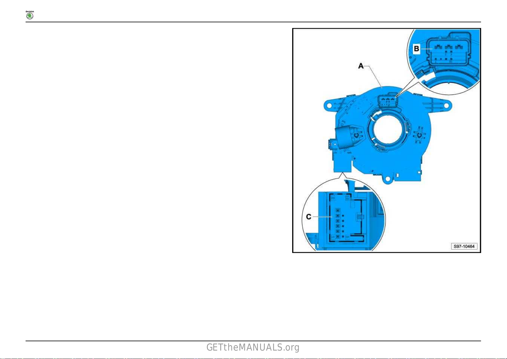
1.3 Control unit for IT 1 -J794- operating unit for multimedia system -E380-
Ausgabe 05.2016
Page 47

RAPID NH
GETtheMANUALS.org
1.3.1 Fitting location
Fitting Locations
No. 804 / 7
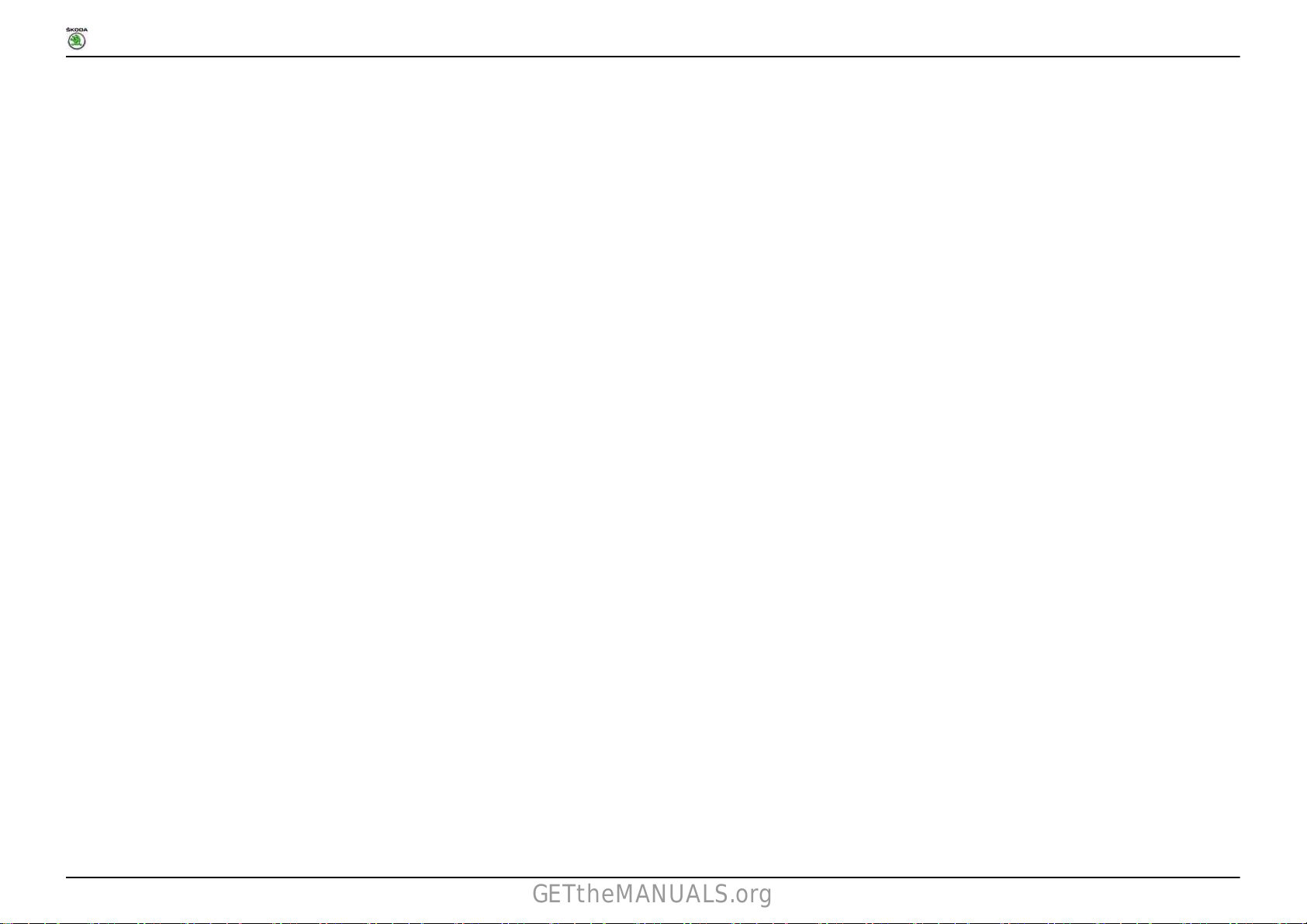
A - Control unit for IT 1 -J794- operating unit for multimedia system -E380B - 12-pin connector, at wiring harness - T12f
C - 5-pin connector, at wiring harness - T5l
Ausgabe 05.2016
Page 48

RAPID NH
GETtheMANUALS.org
1.4 Control unit for clearance control -J428-
1.4.1 Fitting location
Fitting Locations
No. 804 / 8
A - Control unit for clearance control -J428B - 8-pin connector, at wiring harness - T8l
Ausgabe 05.2016
Page 49

RAPID NH
GETtheMANUALS.org
1.5 Entry and start authorisation control unit - J518-
1.5.1 Fitting location (only for left-hand drive vehicles)
Fitting Locations
No. 804 / 9
A - Entry and start authorisation control unit - J518-
Ausgabe 05.2016
Page 50

RAPID NH
GETtheMANUALS.org
B - 32-pin connector, at wiring harness - T32b
1.5.2 Fitting location (only for right-hand drive vehicles)
Fitting Locations
No. 804 / 10
A - Entry and start authorisation control unit - J518B - 32-pin connector, at wiring harness - T32b
Ausgabe 05.2016
Page 51

RAPID NH
GETtheMANUALS.org
1.6 Control unit for cornering light and headlight range control -J745-
1.6.1 Fitting location (only for left-hand drive vehicles)
Fitting Locations
No. 804 / 11
A - Control unit for cornering light and headlight range control -J745-
Ausgabe 05.2016
Page 52

RAPID NH
GETtheMANUALS.org
B - 26-pin connector, at wiring harness - T26
1.6.2 Fitting location (only for right-hand drive vehicles)
Fitting Locations
No. 804 / 12
A - Control unit for cornering light and headlight range control -J745B - 26-pin connector, at wiring harness - T26
Ausgabe 05.2016
Page 53
RAPID NH
GETtheMANUALS.org
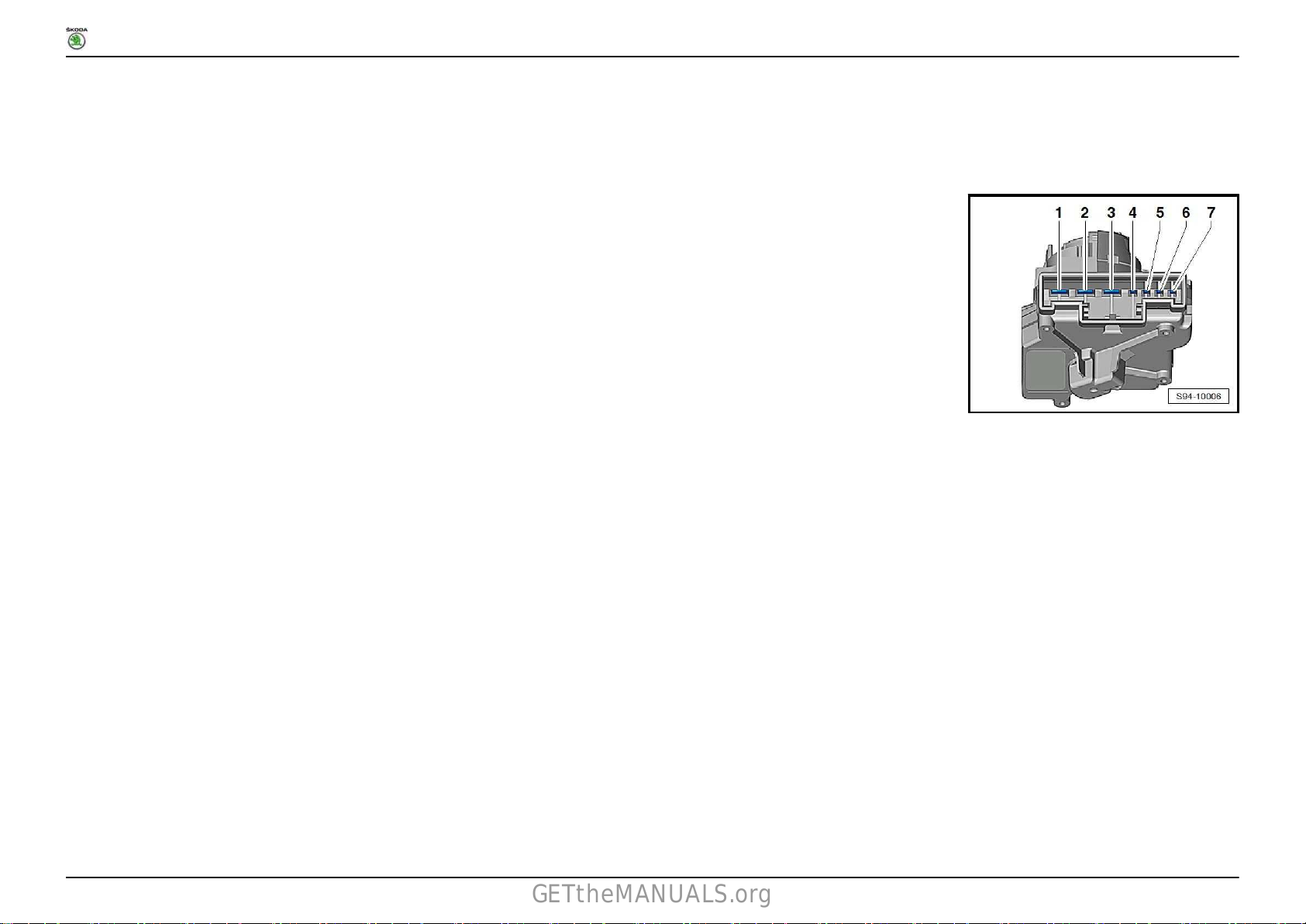
1.7 Ignition starter switch -D-
1.7.1 Pin assignment
1 - T7a15
2 - T7a30
3 - T7a50
4 - T7aP
5 - T7a86s
6 - T7a75
7 - T7a30
Fitting Locations
No. 804 / 13
Ausgabe 05.2016
Page 54

RAPID NH
GETtheMANUALS.org
1.8 Multi-function steering wheel control unit -J453-
1.8.1 Fitting location
In multi-function steering wheel -arrow-.
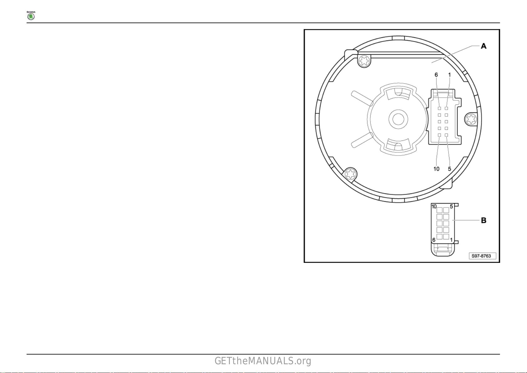
1.9 Coil -F350-
1.9.1 Pin assignment
Fitting Locations
No. 804 / 14
Ausgabe 05.2016
Page 55
RAPID NH
GETtheMANUALS.org
Fitting Locations
No. 804 / 15
A - Coil -F350B - 12-pin connector, at wiring harness - T12a
C - 16-pin connector, at wiring harness - T16a
Ausgabe 05.2016
Page 56

RAPID NH
GETtheMANUALS.org
1.10 Steering column combination switch -E595-
1.10.1 Pin assignment
Fitting Locations
No. 804 / 16
A - Steering column combination switch -E595-
Ausgabe 05.2016
Page 57
RAPID NH
GETtheMANUALS.org
B - 10-pin connector, at wiring harness - T10a
C - 16-pin connector, at wiring harness - T16c
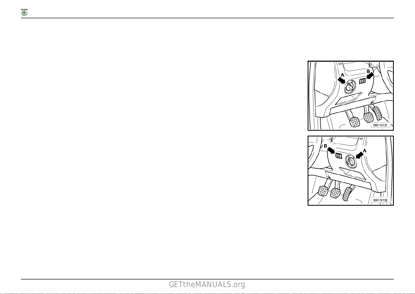
1.11 Headlight range control adjuster -E102-
1.11.1 Fitting location (only for vehicles with
left-hand drive)
At the left dash panel, -arrow B-.
1.11.2 Fitting location (only for vehicles with
right-hand drive)
At the right dash panel, -arrow B-.
Fitting Locations
No. 804 / 17
Ausgabe 05.2016
Page 58

RAPID NH
GETtheMANUALS.org
1.12 Light switch -E1-
1.12.1 Fitting location (only for vehicles with
left-hand drive)
At the left dash panel, -arrow A-.
1.12.2 Fitting location (only for vehicles with
right-hand drive)
At the right dash panel, -arrow A-.
Fitting Locations
No. 804 / 18
1.12.3 Pin assignment
Ausgabe 05.2016
Page 59
RAPID NH
GETtheMANUALS.org
Fitting Locations
No. 804 / 19
A - Light switch -E1B - 10-pin connector, at wiring harness - T10e
1.13 Electronic steering column lock control unit -J764-
Ausgabe 05.2016
Page 60

RAPID NH
GETtheMANUALS.org
1.13.1 Fitting location (only for left-hand drive vehicles)
Fitting Locations
No. 804 / 20
A - Electronic steering column lock control unit -J764B - 16-pin connector, at wiring harness - T16f
Ausgabe 05.2016
Page 61

RAPID NH
GETtheMANUALS.org
1.13.2 Fitting location (only for right-hand drive vehicles)
Fitting Locations
No. 804 / 21
A - Electronic steering column lock control unit -J764B - 16-pin connector, at wiring harness - T16f
Ausgabe 05.2016
Page 62

RAPID NH
GETtheMANUALS.org
Fitting Locations
1.14 Control unit in dash panel insert -J285- Immobilizer control unit -J362-
1.14.1 Pin assignment, as of May 2015
No. 804 / 22
A - Control unit in dash panel insert -J285- Immobilizer control unit -J362B - 18-pin connector, at wiring harness - T18a
Ausgabe 05.2016
Page 63

RAPID NH
GETtheMANUALS.org
18-pin connector -T18a-
1 - Terminal 30 - Input
2 - not assigned
3 - not assigned
4 - not assigned
5 - not assigned
6 - not assigned
7 - Handbrake warning switch -F98 - Immobilizer reading coil -D2-
9 - Immobilizer reading coil -D210 - Terminal 31 - Input
11 - Terminal 31 - sender earth - output
12 - not assigned
13 - not assigned
14 - Fuel gauge sender -G15 - Fuel gauge sender -G16 - not assigned
17 - CAN L, convenience, control unit in dash panel insert -J28518 - CAN H, convenience, control unit in dash panel insert -J285-
Fitting Locations
No. 804 / 23
1.14.2 Pin assignment, as of May 2016
Ausgabe 05.2016
Page 64

RAPID NH
GETtheMANUALS.org
Fitting Locations
No. 804 / 24
A - Control unit in dash panel insert -J285- Immobilizer control unit -J362B - 18-pin connector, at wiring harness - T18a
18-pin connector -T18a-
1 - Terminal 30 - Input
2 - not assigned
Ausgabe 05.2016
Page 65

RAPID NH
GETtheMANUALS.org
3 - Speed - output (only for vehicles with Taxi equipment)
4 - not assigned
5 - not assigned
6 - not assigned
7 - Handbrake warning switch -F9-
8 - Immobilizer reading coil -D2-
9 - Immobilizer reading coil -D210 - Terminal 31 - Input
11 - Terminal 31 - sender earth - output
12 - not assigned
13 - not assigned
14 - Fuel gauge sender -G15 - Fuel gauge sender -G16 - not assigned
17 - CAN L, convenience, control unit in dash panel insert -J28518 - CAN H, convenience, control unit in dash panel insert -J285-
Fitting Locations
1.15 Onboard control unit - J519 Data bus diagnostic interface -J533-
No. 804 / 25
1.15.1 Fitting location (only for left-hand drive
vehicles)
Below the left dash panel, -arrow-.
Ausgabe 05.2016
Page 66

RAPID NH
GETtheMANUALS.org
Fitting Locations
No. 804 / 26
1.15.2 Fitting
vehicles)
Below the right dash panel -arrow-.
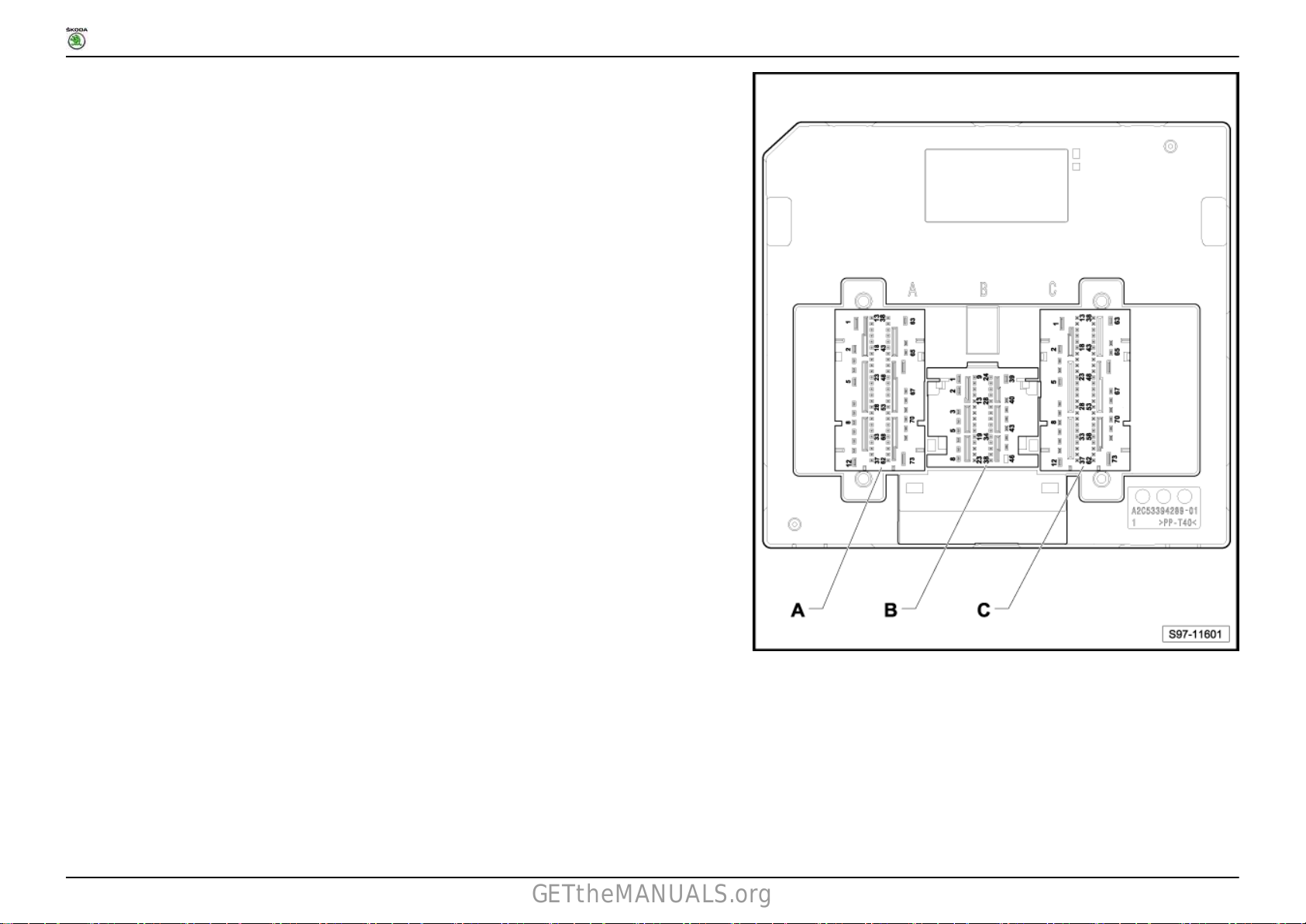
1.15.3 Pin assignment, as of May 2015
location (only for right-hand drive
Ausgabe 05.2016
Page 67
RAPID NH
GETtheMANUALS.org
Fitting Locations
No. 804 / 27
A - 73-pin connector - T73a
B - 46-pin connector -T46b
C - 73-pin connector - T73c
73-pin connector -T73a-
1 - Input (31) - for central locking
Ausgabe 05.2016
Page 68

RAPID NH
GETtheMANUALS.org
2 - Output for central locking motor in rear lid -V533 - Output for central locking motor in rear right door, lock -V2154 - Output for central locking motor in rear right door, lock -V215- , motor for SAFE function of central locking in rear right door -V1645 - not assigned
6 - Output for central locking motor in front passenger door -V577 - Output for central locking motor in front passenger door -V57- , motor for SAFE function of central locking in front passenger door -V1628 - Output for central locking motor in rear left door, lock -V214-
9 - Output for central locking motor in rear left door, lock -V214- , motor for SAFE function of central locking in rear left door -V16310 - Output for central locking motor in driver door -V56- , tank filler flap locking motor -V15511 - Output for central locking motor in driver door -V56- , motor for SAFE function of central locking in driver door -V161- , tank filler flap locking motor -V15512 - Input - terminal 31 - brake mass for windscreen wiper motor -V13 - Output for light detection sensor -G399- (31)
14 - Input of exterior mirror heating button -E23115 - Input of multi-function display call-up button -E8616 - Input of multi-function display call-up button -E8617 - Input of multi-function display, memory switch -E10918 - not assigned
19 - not assigned
20 - not assigned
21 - not assigned
22 - not assigned
23 - Input of central locking lock unit, rear left -F22224 - Input of central locking lock unit, front passenger side -F22125 - Input of central locking lock unit, rear right -F22326 - Input of startstop operation button -E69327 - Input of horn activation -H- (31)
28 - Input of CCS SET button -E227- (RES+)
29 - Input of CCS switch -E45- (off)
30 - Input (56a) of headlight dipperflasher switch -E431 - Input of intermittent wiper switch -E22- (2nd stage)
32 - not assigned
33 - not assigned
34 - not assigned
35 - not assigned
36 - Output for seat heating
37 - Output for deactivation warning light of interior monitoring and vehicle inclination -K248-
Fitting Locations
No. 804 / 28
Ausgabe 05.2016
Page 69

RAPID NH
GETtheMANUALS.org
38 - Input of deactivation button of interior monitoring and vehicle inclination -E61639 - Input of control unit for entry and start authorisation -J518- (wake up wire)
40 - not assigned
41 - Input of ignition starter switch -D- (86s) (for vehicles without entry and start authorisation)
- Input of steering column electronics control unit -J764- (86s) (for vehicles with entry and start authorisation)
42 - Input of light switch -E143 - Input of light switch -E1- (AFL)
44 - not assigned
45 - not assigned
46 - Input (56b) of headlight dipperflasher switch -E447 - Input of light switch -E1- (TFL)
48 - Input of light switch -E1- (58)
49 - not assigned
50 - Input of intermittent wiper switch -E22- (1st stage)
51 - Input of rear wiper switch -E34-
- Output for rear window wiper motor -V1252 - Input of CCS SET button -E227- (SET-)
53 - Input of CCS switch -E45- (onoff)
54 - Input of selector lever locked in position P switch -F31955 - Input of heated rear window button -E230- (31)
56 - Input of central locking lock unit, driver side -F22057 - not assigned
58 - Input of intermittent wiper control -E3859 - not assigned
60 - Output for number plate light, left -X4- , number plate light, right -X561 - not assigned
62 - Input of steering column electronics control unit -J764- (15)
63 - Input - (31)
64 - Output for motor for SAFE function of central locking in driver door -V161- , motor for SAFE function of central locking in front passenger door -V162- , motor for
SAFE function of central locking in rear left door -V163- , motor for SAFE function of central locking in rear right door -V164-
65 - Output for tail and rear fog light bulb, left -M41- (for vehicles with left-hand drive)
- Output for tail and rear fog light bulb, right -M42- (for vehicles with right-hand drive)
66 - Input (30) - right light supply
67 - not assigned
68 - Output for Interior light (31)
69 - Output for tail light bulb, right -M2- , tail light and rear fog light bulb, right -M42- , right brake and tail light bulb -M22-
Fitting Locations
No. 804 / 29
Ausgabe 05.2016
Page 70

RAPID NH
GETtheMANUALS.org
70 - Output for brake and tail light bulb, left -M2171 - Output for turn signal bulb, rear left -M672 - Output for turn signal bulb in exterior mirror, front passenger side -L132- (not for Russia equipment)
- Output for side turn signal bulb, right -M19- (for Russia equipment)
73 - Input for windscreen wiper motor -V- (30)
46-pin connector -T46b-
1 - Output for windscreen wiper motor -V- (2nd stage)
2 - Input (30) - for central locking
3 - Output for fog light bulb, right -L23- , static cornering light, right -M524 - not assigned
5 - Output for dipped beam bulb, right -M31- , gas discharge lamp, right -L146 - Output for day driving light bulb, right -L1757 - Output for main beam bulb, right -M328 - Output for windscreen wiper motor -V- (1st stage)
9 - Input of bonnet contact switch -F26610 - Input of brake light switch -F- (54)
11 - Input of windscreen wiper motor -V12 - Input of reversing light switch -F4- (not valid for vehicles with automatic gearbox)
13 - Input of ambient temperature sensor -G1714 - Input of windscreen washer fluid level sender -G3315 - Input of coolant shortage indicator sender -G3216 - not assigned
17 - Input of brake fluid level warning contact -F3418 - not assigned
19 - not assigned
20 - not assigned
21 - not assigned
22 - Output for side light bulb, left -M123 - Output for turn signal bulb, front right -M724 - not assigned
25 - LIN bus - signal horn for anti-theft alarm system -H826 - LIN bus - Alternator with voltage regulator -CX1- , Battery monitor control unit -J36727 - not assigned
28 - not assigned
Fitting Locations
No. 804 / 30
Ausgabe 05.2016
Page 71

RAPID NH
GETtheMANUALS.org
29 - Input (30) - Reference
30 - not assigned
31 - Input (31) - Reference
32 - not assigned
33 - Output for sender earth (31)
34 - Output for headlight washer system relay -J3935 - Output for turn signal bulb, front left -M536 - Output for side light bulb, right -M337 - not assigned
38 - not assigned
39 - not assigned
40 - Output for fog light bulb, left -L22- , static cornering light, left -M5141 - not assigned
42 - Output for main beam bulb, left -M3043 - Output for day driving light bulb, left -L17444 - Output for dipped beam bulb, left -M29- , gas discharge lamp, left -L1345 - Output for left footwell light -W9- , right footwell light -W10- , storage compartment illumination bulb -L12046 - Output for high tone horn -H2- , low tone horn -H7-
Fitting Locations
No. 804 / 31
73-pin connector -T73c-
1 - Input (30) - left light supply
2 - Input for heated exterior mirror driver's side -Z4- , heated exterior mirror front passenger's side -Z5-
3 - Output for reversing light bulb, left -M16- , reversing light bulb, right -M17- , automatic anti-dazzle interior mirror -Y7-
4 - not assigned
5 - Input (30) - supply for heated exterior mirror driver's side -Z4- , heated exterior mirror front passenger's side -Z5-
6 - not assigned
7 - Output for tail light bulb, left -M4- , tail and rear fog light bulb, left -M41- , left brake and tail light bulb -M21-
8 - Output for brake and tail light bulb, right -M22-
9 - Output for bulb for high level brake light -M25- (54)
10 - Output for turn signal bulb, rear right -M811 - Output for turn signal bulb in exterior mirror, driver's side -L131- (not for Russia equipment)
- Output for side turn signal bulb, left -M18- (for Russia equipment)
12 - Input (30) for high tone horn -H2- , low tone horn -H713 - LIN bus Multi-function steering wheel control unit -J45314 - LIN bus window regulator motor, driver side -V147-
Ausgabe 05.2016
Page 72

RAPID NH
GETtheMANUALS.org
15 - LIN bus Air humidity, rain and light detector sensor -G823- , sensor for anti-theft alarm system -G578- , humidity sender -G35516 - not assigned
17 - not assigned
18 - not assigned
19 - not assigned
20 - Input of central locking lock unit, front passenger side -F22121 - Input of central locking lock unit, driver side -F22022 - Input of rear lid lock unit -F256- (31)
23 - Input of rear lid handle release button -E234- (31)
24 - Input of door contact switch, rear left -F1025 - Input of door contact switch, driver side -F2- (31)
26 - Input of door contact switch, front passenger side -F3- (31)
27 - Input of door contact switch, rear right -F1128 - Input of interior button for central locking driver's side -E30829 - Input of turn signal switch -E2- (right turn signal) (31)
30 - Input of hazard warning light button -E229- (31)
31 - Input of fog light and rear fog light switch -E2332 - Input of turn signal switch -E2- (left turn signal) (31)
33 - Output for terminal 15 voltage supply relay -J329- (for vehicles with entry and start authorisation)
34 - Output - signal (15)
35 - not assigned
36 - not assigned
37 - not assigned
38 - not assigned
39 - not assigned
40 - CAN bus extended high
41 - CAN bus extended low
42 - Drive train CAN bus high (switched)
43 - Drive train CAN bus low (switched)
44 - Drive train CAN bus, high
45 - Drive train CAN bus, low
46 - Convenience CAN bus, high
47 - Convenience CAN bus, low
48 - not assigned
49 - not assigned
50 - not assigned
Fitting Locations
No. 804 / 32
Ausgabe 05.2016
Page 73

RAPID NH
GETtheMANUALS.org
51 - Output for startstop operation warning light -K25952 - Output for heated rear window warning light -K1053 - not assigned
54 - Output for hazard warning light system warning light -K6- , bulb for button illumination -L7655 - Output for warning light for SAFE function of central locking -K13356 - Input of light detection sensor -G39957 - Input of ignition starter switch -D- (15) (for vehicles without entry and start authorisation)
- Input of steering column electronics control unit -J764- (15) (for vehicles with entry and start authorisation)
58 - not assigned
59 - not assigned
60 - not assigned
61 - Output for interior locking warning light, driver side -K17462 - Output for X contact relief relay -J5963 - Input (30)
64 - not assigned
65 - not assigned
66 - Output for heated rear window -Z167 - Output (58d)
68 - not assigned
69 - Output for interior light front -W1- , reading light rear left -W11- , reading light rear right -W12- , interior light right -W43- , glovebox light -W6- , luggage compartment
light, left -W1870 - not assigned
71 - not assigned
72 - not assigned
73 - Input for heated rear window -Z1- (30a_2)
Fitting Locations
No. 804 / 33
1.15.4 Pin assignment, as of May 2016
Ausgabe 05.2016
Page 74

RAPID NH
GETtheMANUALS.org
Fitting Locations
No. 804 / 34
A - 73-pin connector - T73a
B - 46-pin connector -T46b
C - 73-pin connector - T73c
73-pin connector -T73a-
1 - Input (31) - for central locking
Ausgabe 05.2016
Page 75

RAPID NH
GETtheMANUALS.org
2 - Output for central locking motor in rear lid -V533 - Output for central locking motor in rear right door, lock -V2154 - Output for central locking motor in rear right door, lock -V215- , motor for SAFE function of central locking in rear right door -V1645 - not assigned
6 - Output for central locking motor in front passenger door -V577 - Output for central locking motor in front passenger door -V57- , motor for SAFE function of central locking in front passenger door -V1628 - Output for central locking motor in rear left door, lock -V214-
9 - Output for central locking motor in rear left door, lock -V214- , motor for SAFE function of central locking in rear left door -V16310 - Output for central locking motor in driver door -V56- , tank filler flap locking motor -V15511 - Output for central locking motor in driver door -V56- , motor for SAFE function of central locking in driver door -V161- , tank filler flap locking motor -V15512 - Input - terminal 31 - brake mass for windscreen wiper motor -V13 - Output for light detection sensor -G399- (31)
14 - Input of exterior mirror heating button -E23115 - Input of multi-function display call-up button -E8616 - Input of multi-function display call-up button -E8617 - Input of multi-function display, memory switch -E10918 - Input of heated windscreen button -E62719 - not assigned
20 - not assigned
21 - not assigned
22 - not assigned
23 - Input of central locking lock unit, rear left -F22224 - Input of central locking lock unit, front passenger side -F22125 - Input of central locking lock unit, rear right -F22326 - Input of startstop operation button -E69327 - Input of horn activation -H- (31)
28 - Input of CCS SET button -E227- (RES+)
29 - Input of CCS switch -E45- (off)
30 - Input (56a) of headlight dipperflasher switch -E431 - Input of intermittent wiper switch -E22- (2nd stage)
32 - Input of rear wiper switch -E34- (HW)
33 - not assigned
34 - not assigned
35 - not assigned
36 - Output for seat heating
37 - Output for deactivation warning light of interior monitoring and vehicle inclination -K248-
Fitting Locations
No. 804 / 35
Ausgabe 05.2016
Page 76
RAPID NH
GETtheMANUALS.org
38 - Input of deactivation button of interior monitoring and vehicle inclination -E61639 - Input of control unit for entry and start authorisation -J518- (wake up wire)
40 - not assigned
41 - Input of ignition starter switch -D- (86s) (for vehicles without entry and start authorisation)
- Input of steering column electronics control unit -J764- (86s) (for vehicles with entry and start authorisation)
42 - Input of light switch -E143 - Input of light switch -E1- (AFL)
44 - Input of rear wiper switch -E34- (53c)
45 - not assigned
46 - Input (56b) of headlight dipperflasher switch -E447 - Input of light switch -E1- (TFL)
48 - Input of light switch -E1- (58)
49 - not assigned
50 - Input of intermittent wiper switch -E22- (1st stage)
51 - Input of rear wiper switch -E34-
- Output for rear window wiper motor -V1252 - Input of CCS SET button -E227- (SET-)
53 - Input of CCS switch -E45- (onoff)
54 - Input of selector lever locked in position P switch -F31955 - Input of heated rear window button -E230- (31)
56 - Input of central locking lock unit, driver side -F22057 - not assigned
58 - Input of intermittent wiper control -E3859 - not assigned
60 - Output for number plate light, left -X4- , number plate light, right -X561 - not assigned
62 - Input of steering column electronics control unit -J764- (15)
63 - Input - (31)
64 - Output for motor for SAFE function of central locking in driver door -V161- , motor for SAFE function of central locking in front passenger door -V162- , motor for
65 - Output for tail and rear fog light bulb, left -M41- (for vehicles with left-hand drive)
66 - Input (30) - right light supply
67 - not assigned
68 - Output for Interior light (31)
69 - Output for tail light bulb, right -M2- , tail light and rear fog light bulb, right -M42- , right brake and tail light bulb -M22-
SAFE function of central locking in rear left door -V163- , motor for SAFE function of central locking in rear right door -V164-
- Output for tail and rear fog light bulb, right -M42- (for vehicles with right-hand drive)
Fitting Locations
No. 804 / 36
Ausgabe 05.2016
Page 77

RAPID NH
GETtheMANUALS.org
70 - Output for brake and tail light bulb, left -M2171 - Output for turn signal bulb, rear left -M672 - Output for turn signal bulb in exterior mirror, front passenger side -L132- (not for Russia equipment)
- Output for side turn signal bulb, right -M19- (for Russia equipment)
73 - Input for windscreen wiper motor -V- (30)
46-pin connector -T46b-
1 - Output for windscreen wiper motor -V- (2nd stage)
2 - Input (30) - for central locking windscreen and rear window washer pump -V59- , rear window wiper motor -V123 - Output for fog light bulb, right -L23- , static cornering light, right -M524 - Output for windscreen and rear window washer pump -V595 - Output for dipped beam bulb, right -M31- , gas discharge lamp, right -L146 - Output for day driving light bulb, right -L1757 - Output for main beam bulb, right -M328 - Output for windscreen wiper motor -V- (1st stage)
9 - Input of bonnet contact switch -F26610 - Input of brake light switch -F- (54)
11 - Input of windscreen wiper motor -V12 - Input of reversing light switch -F4- (not valid for vehicles with automatic gearbox)
13 - Input of ambient temperature sensor -G1714 - Input of windscreen washer fluid level sender -G3315 - Input of coolant shortage indicator sender -G3216 - not assigned
17 - Input of brake fluid level warning contact -F3418 - not assigned
19 - not assigned
20 - not assigned
21 - not assigned
22 - Output for side light bulb, left -M123 - Output for turn signal bulb, front right -M724 - not assigned
25 - LIN bus - signal horn for anti-theft alarm system -H826 - LIN bus - Alternator with voltage regulator -CX1- , Battery monitor control unit -J36727 - not assigned
28 - not assigned
Fitting Locations
No. 804 / 37
Ausgabe 05.2016
Page 78

RAPID NH
GETtheMANUALS.org
29 - Input (30) - Reference
30 - not assigned
31 - Input (31) - Reference
32 - not assigned
33 - Output for sender earth (31)
34 - Output for headlight washer system relay -J3935 - Output for turn signal bulb, front left -M536 - Output for side light bulb, right -M337 - not assigned
38 - Output for heated windscreen
39 - not assigned
40 - Output for fog light bulb, left -L22- , static cornering light, left -M5141 - Output for windscreen and rear window washer pump -V5942 - Output for main beam bulb, left -M3043 - Output for day driving light bulb, left -L17444 - Output for dipped beam bulb, left -M29- , gas discharge lamp, left -L1345 - Output for left footwell light -W9- , right footwell light -W10- , storage compartment illumination bulb -L120- , driver door ambient lighting bulb -L164- , Front
passenger door ambient lighting bulb -L165-
46 - Output for high tone horn -H2- , low tone horn -H7-
Fitting Locations
No. 804 / 38
73-pin connector -T73c-
1 - Input (30) - left light supply
2 - Input for heated exterior mirror driver's side -Z4- , heated exterior mirror front passenger's side -Z5-
3 - Output for reversing light bulb, left -M16- , reversing light bulb, right -M17- , automatic anti-dazzle interior mirror -Y7- , rear view camera -R189-
4 - not assigned
5 - Input (30) - supply for heated exterior mirror driver's side -Z4- , heated exterior mirror front passenger's side -Z5-
6 - not assigned
7 - Output for tail light bulb, left -M4- , tail and rear fog light bulb, left -M41- , left brake and tail light bulb -M21-
8 - Output for brake and tail light bulb, right -M22-
9 - Output for bulb for high level brake light -M25- (54)
10 - Output for turn signal bulb, rear right -M811 - Output for turn signal bulb in exterior mirror, driver's side -L131- (not for Russia equipment)
- Output for side turn signal bulb, left -M18- (for Russia equipment)
12 - Input (30) for high tone horn -H2- , low tone horn -H713 - LIN bus Multi-function steering wheel control unit -J453-
Ausgabe 05.2016
Page 79

RAPID NH
GETtheMANUALS.org
14 - LIN bus window regulator motor, driver side -V14715 - LIN bus Air humidity, rain and light detector sensor -G823- , sensor for anti-theft alarm system -G578- , humidity sender -G35516 - not assigned
17 - not assigned
18 - not assigned
19 - not assigned
20 - Input of central locking lock unit, front passenger side -F22121 - Input of central locking lock unit, driver side -F22022 - Input of rear lid lock unit -F256- (31)
23 - Input of rear lid handle release button -E234- (31)
24 - Input of door contact switch, rear left -F1025 - Input of door contact switch, driver side -F2- (31)
26 - Input of door contact switch, front passenger side -F3- (31)
27 - Input of door contact switch, rear right -F1128 - Input of interior button for central locking driver's side -E30829 - Input of turn signal switch -E2- (right turn signal) (31)
30 - Input of hazard warning light button -E229- (31)
31 - Input of fog light and rear fog light switch -E2332 - Input of turn signal switch -E2- (left turn signal) (31)
33 - Output for terminal 15 voltage supply relay -J329- (for vehicles with entry and start authorisation)
34 - Output - signal (15)
35 - not assigned
36 - not assigned
37 - not assigned
38 - not assigned
39 - not assigned
40 - CAN bus extended high
41 - CAN bus extended low
42 - Drive train CAN bus high (switched)
43 - Drive train CAN bus low (switched)
44 - Drive train CAN bus, high
45 - Drive train CAN bus, low
46 - Convenience CAN bus, high
47 - Convenience CAN bus, low
48 - not assigned
49 - not assigned
Fitting Locations
No. 804 / 39
Ausgabe 05.2016
Page 80

RAPID NH
GETtheMANUALS.org
50 - Output for heated windscreen warning light -K12251 - Output for startstop operation warning light -K25952 - Output for heated rear window warning light -K1053 - not assigned
54 - Output for hazard warning light system warning light -K6- , bulb for button illumination -L7655 - Output for warning light for SAFE function of central locking -K13356 - Input of light detection sensor -G39957 - Input of ignition starter switch -D- (15) (for vehicles without entry and start authorisation)
- Input of steering column electronics control unit -J764- (15) (for vehicles with entry and start authorisation)
58 - not assigned
59 - not assigned
60 - not assigned
61 - Output for interior locking warning light, driver side -K17462 - Output for X contact relief relay -J5963 - Input (30)
64 - not assigned
65 - not assigned
66 - Output for heated rear window -Z167 - Output (58d)
68 - not assigned
69 - Output for interior light front -W1- , reading light rear left -W11- , reading light rear right -W12- , interior light right -W43- , glovebox light -W6- , luggage compartment
light, left -W1870 - not assigned
71 - not assigned
72 - not assigned
73 - Input for heated rear window -Z1- (30a_2)
Fitting Locations
No. 804 / 40
1.16 Engine control unit -J623-
1.16.1 Fitting location
Ausgabe 05.2016
Page 81
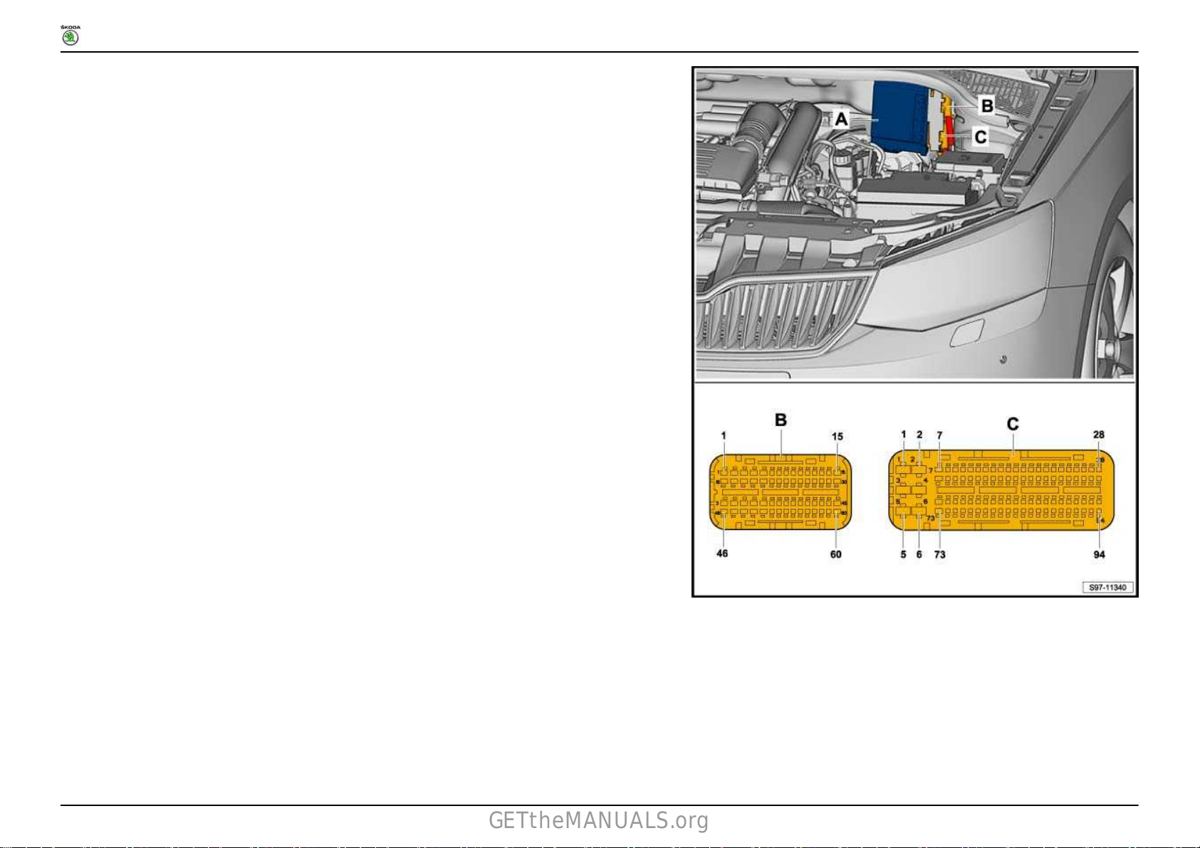
RAPID NH
GETtheMANUALS.org
Fitting Locations
No. 804 / 41
A - Engine control unit -J623B - 94-pin connector, at wiring harness - T94a
C - 60-pin connector, at wiring harness - T60a
1.17 Automatic gearbox control unit -J217-
Ausgabe 05.2016
Page 82

RAPID NH
GETtheMANUALS.org
1.17.1 Fitting location
Fitting Locations
No. 804 / 42
A - Automatic gearbox control unit -J217B - 52-pin connector, at wiring harness - T52a
Ausgabe 05.2016
Page 83

RAPID NH
GETtheMANUALS.org
1.18 Windscreen wiper motor -V-
1.18.1 Fitting location (only for vehicles with
left-hand drive)
In plenum chamber, left -arrow-.
1.18.2 Fitting location (only for vehicles with
right-hand drive)
In plenum chamber, right -arrow-.
Fitting Locations
No. 804 / 43
1.18.3 Pin assignment
Ausgabe 05.2016
Page 84

RAPID NH
GETtheMANUALS.org
Fitting Locations
No. 804 / 44
A - Windscreen wiper motor -VB - 4-pin connector, at wiring harness - T4a
1.19 Battery monitor control unit -J367-
Ausgabe 05.2016
Page 85

RAPID NH
GETtheMANUALS.org
1.19.1 Fitting location
Fitting Locations
No. 804 / 45
A - Battery monitor control unit -J367B - 2-pin connector, at wiring harness - T2d
Ausgabe 05.2016
Page 86

RAPID NH
GETtheMANUALS.org
1.20 Power steering control unit -J500-
electromechanical power steering
1.20.1 Fitting location (only for vehicles with
left-hand drive)
below the left dash panel, -arrow-.
1.20.2 Fitting location (only for vehicles with
right-hand drive)
Below the right dash panel, -arrow-.
Fitting Locations
No. 804 / 46
Ausgabe 05.2016
Page 87

RAPID NH
GETtheMANUALS.org
1.21 Radiator fan control unit -J293-
1.21.1 Fitting location (not valid for engine
identification characters CXMA)
In engine compartment, front left -arrow-.
1.21.2 Pin assignment (not valid for engine identification characters CXMA)
Fitting Locations
No. 804 / 47
Ausgabe 05.2016
Page 88

RAPID NH
GETtheMANUALS.org
Fitting Locations
No. 804 / 48
A - Radiator fan control unit -J293B - 10-pin connector, at wiring harness - T10o
Ausgabe 05.2016
Page 89

RAPID NH
GETtheMANUALS.org
Fitting Locations
1.21.3 Pin assignment (applies to engine identification characters CXMA)
No. 804 / 49
A - Radiator fan control unit -J293B - 4-pin connector, at wiring harness - T4an
Ausgabe 05.2016
Page 90
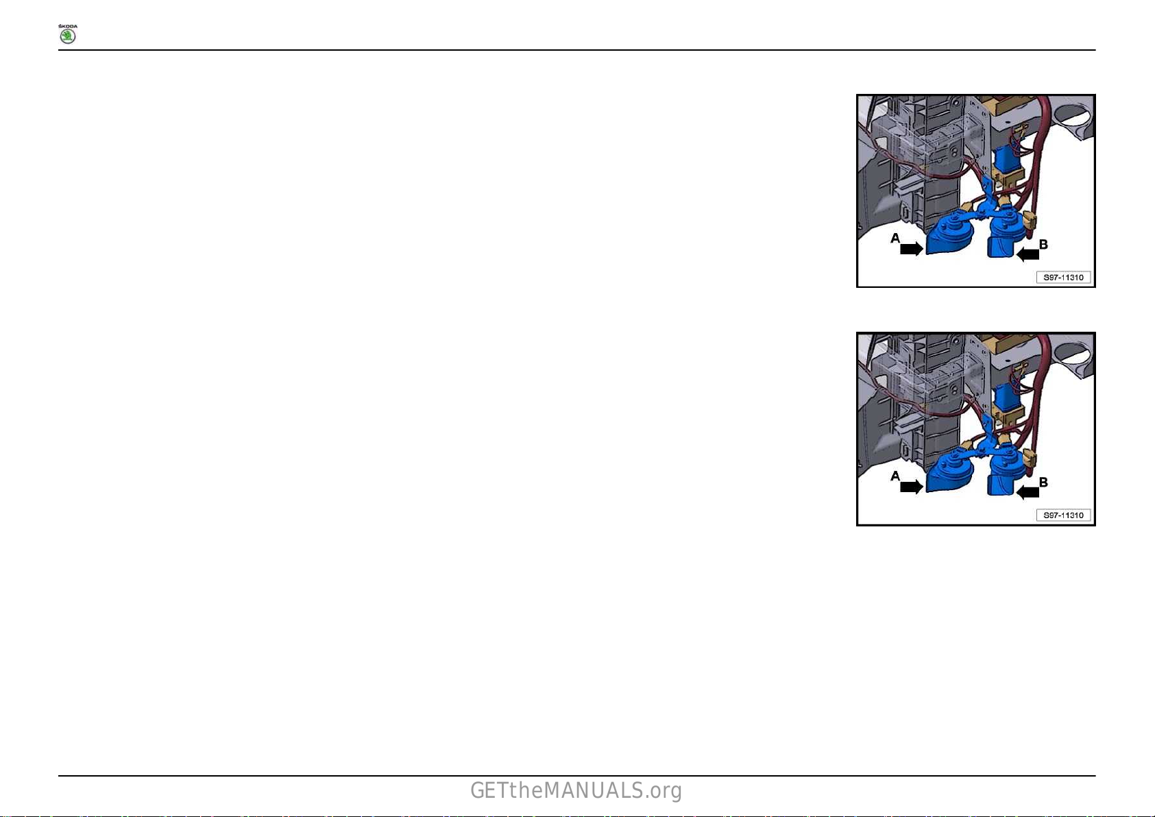
RAPID NH
GETtheMANUALS.org
1.22 Low tone horn -H7-
1.22.1 Fitting location
In engine compartment, front left -arrow B-.
1.23 High tone horn -H2-
1.23.1 Fitting location
In engine compartment, front left -arrow A-.
Fitting Locations
No. 804 / 50
Ausgabe 05.2016
Page 91

RAPID NH
GETtheMANUALS.org
1.24 Automatic glow period control unit -J179-
1.24.1 Fitting location
At the battery cover -1-.
1.25 Double clutch gearbox mechatronics -J743-
1.25.1 Fitting location
On the double clutch gearbox -arrow-.
Fitting Locations
No. 804 / 51
Ausgabe 05.2016
Page 92

RAPID NH
GETtheMANUALS.org
1.25.2 Pin assignment
A - Double clutch gearbox mechatronics -J743B - 25-pin connector, at wiring harness - T25a
Fitting Locations
No. 804 / 52
1.26 Lambda probe after catalytic converter -G130-
1.26.1 Fitting location
On the pre-exhaust pipe -arrow-.
Note
The fitting location of the lambda probe can differ depending on
the engine type.
Ausgabe 05.2016
Page 93

RAPID NH
GETtheMANUALS.org
1.26.2 Pin assignment
Fitting Locations
No. 804 / 53
A - 4-pin connector, at wiring harness - T4g
B - 6-pin connector, at wiring harness - T6j
Ausgabe 05.2016
Page 94

RAPID NH
GETtheMANUALS.org
1.27 Lambda probe -G39-
1.27.1 Fitting location
On the exhaust manifold -arrow-.
Note
The fitting location of the lambda probe can differ depending on
the engine type.
1.27.2 Pin assignment
Fitting Locations
No. 804 / 54
Ausgabe 05.2016
Page 95

RAPID NH
GETtheMANUALS.org
A - 4-pin connector, at wiring harness - T4f
B - 6-pin connector, at wiring harness - T6h
1.28 ABS control unit -J104-
1.28.1 Fitting location
Fitting Locations
No. 804 / 55
Ausgabe 05.2016
Page 96

RAPID NH
GETtheMANUALS.org
Fitting Locations
No. 804 / 56
A - ABS control unit -J104B - 38-pin connector, at wiring harness - T38a
Ausgabe 05.2016
Page 97

RAPID NH
GETtheMANUALS.org
1.29 Airbag control unit -J234-
1.29.1 Fitting location (only for vehicles with
left-hand drive)
Below the front centre console -arrow-.
1.29.2 Fitting location (only for vehicles with
right-hand drive)
Below the front centre console -arrow-.
Fitting Locations
No. 804 / 57
1.29.3 Pin assignment
Ausgabe 05.2016
Page 98

RAPID NH
GETtheMANUALS.org
Fitting Locations
No. 804 / 58
A - Airbag control unit -J234B - 50-pin connector, at wiring harness - T50a
Ausgabe 05.2016
Page 99

RAPID NH
GETtheMANUALS.org
1.30 Heated front seat control unit -J774-
1.30.1 Fitting location (only for vehicles with
left-hand drive)
Below the dash panel, near centre console -arrow-.
1.30.2 Fitting location (only for vehicles with
right-hand drive)
Below the dash panel, near centre console -arrow-.
Fitting Locations
No. 804 / 59
1.31 Heater control unit -J65-
1.31.1 Pin assignment
Ausgabe 05.2016
Page 100

RAPID NH
GETtheMANUALS.org
Fitting Locations
No. 804 / 60
A - Heater control unit -J65B - 16-pin connector, at wiring harness - T16h 16-pin connector, at wiring harness - T16e
C - 5-pin connector, at wiring harness - T5f
D - not assigned 18-pin connector, on wiring harness - T18b
Ausgabe 05.2016
 Loading...