

SKODA Karoq 2018, Kodiaq 2017, Kodiaq 2019, Octavia III 2013, Octavia III 2014 Workshop Manual
...
Protected by copyright. Copying for private or commercial purposes, in part or in whole, is not permitted
unless authorised by ŠKODA AUTO A. S. ŠKODA AUTO A. S. does not guarantee or accept any liability
with respect to the correctness of information in this document. Copyright by ŠKODA AUTO A. S.
Service
GETtheMANUALS.org
Workshop Manual
Karoq 2018 ➤ , Kodiaq 2017 ➤ ,
K
Octavia III 2014 ➤ , Rapid NH 2013 ➤ ,
Rapid NH 2014 ➤ , Superb III 2015 ➤ ,
Yeti 2010 ➤ , Yeti 2011 ➤
odiaq 2019 ➤ , Octavia III 2013 ➤ ,
Fuel system - Petrol engines
Engine ID
CJZA CJZB CJZC CJZD
CZCACZDACZEACYVACYVBDADADKRCDKLDDKR
CJSA CJSB CJSC CJXA
DKZ
A
DLBA
DNU
A
CHZBCHZCCHZ
D
CHHACHHBCZPACZPBDKT
CHZJ
CHP
A
F
B
Edition 12.2018
Service Department. Technical Information
Protected by copyright. Copying for private or commercial purposes, in part or in whole, is not permitted
unless authorised by ŠKODA AUTO A. S. ŠKODA AUTO A. S. does not guarantee or accept any liability
with respect to the correctness of information in this document. Copyright by ŠKODA AUTO A. S.
List of Workshop Manual Repair Groups
GETtheMANUALS.org
R
epa i r G r o u p
00 - Technical data
20 - Fuel supply system
Service
Technical information should always be available to the foremen and mechanics, because their
careful
safety. In addition, the normal basic safety precautions for working on motor vehicles must, as a
matter of course, be observed.
All rights reserved.
No reproduction without prior agreement from publisher.
Copyright © 2018 ŠKODA AUTO a. s. D4B8052B85F
and constant adherence to the instructions is essential to ensure vehicle road-worthiness and

Protected by copyright. Copying for private or commercial purposes, in part or in whole, is not permitted
unless authorised by ŠKODA AUTO A. S. ŠKODA AUTO A. S. does not guarantee or accept any liability
with respect to the correctness of information in this document. Copyright by ŠKODA AUTO A. S.
Karoq 2018 ➤ , Kodiaq 2017 ➤ , Kodiaq 2019 ➤ , Octavia III 2013 ➤ , Oc ...
GETtheMANUALS.org
Fuel system - Petrol engines - Edition 12.2018
Contents
00 - Technical data
1 Denomination
1.1 Engine number, engine data . . . . . . . . . . . . . . . . . . . . . . . . . . . . . . . . . . . . . . . . . . . . . . . . 1
2 Safety instructions . . . . . . . . . . . . . . . . . . . . . . . . . . . . . . . . . . . . . . . . . . . . . . . . . . . . . . . . 4
2.1 Safety precautions when working on fuel supply system . . . . . . . . . . . . . . . . . . . . . . . . . . 4
2.2 Safety precautions when working on vehicles with start-stop system . . . . . . . . . . . . . . . . 5
2.3 Safety precautions during road tests in which testing and measuring equipment is used . . 5
3 General points . . . . . . . . . . . . . . . . . . . . . . . . . . . . . . . . . . . . . . . . . . . . . . . . . . . . . . . . . . 6
3.1 Cleanliness rules when working on the parking/auxiliary heater and fuel system . . . . . . . . 6
4 Repair instructions . . . . . . . . . . . . . . . . . . . . . . . . . . . . . . . . . . . . . . . . . . . . . . . . . . . . . . . . 7
4.1 General repair instructions . . . . . . . . . . . . . . . . . . . . . . . . . . . . . . . . . . . . . . . . . . . . . . . . . . 7
4.2 Contact corrosion . . . . . . . . . . . . . . . . . . . . . . . . . . . . . . . . . . . . . . . . . . . . . . . . . . . . . . . . 7
4.3 Cable routing and securing . . . . . . . . . . . . . . . . . . . . . . . . . . . . . . . . . . . . . . . . . . . . . . . . 7
20 - Fuel supply system
1 Fuel tank . . . . . . . . . . . . . . . . . . . . . . . . . . . . . . . . . . . . . . . . . . . . . . . . . . . . . . . . . . . . . . . . 8
1.1 Assembly overview - fuel tank
1.2 Removing and installing the fuel tank . . . . . . . . . . . . . . . . . . . . . . . . . . . . . . . . . . . . . . . . . . 24
1.3 Drain the fuel tank . . . . . . . . . . . . . . . . . . . . . . . . . . . . . . . . . . . . . . . . . . . . . . . . . . . . . . . . 64
2 Fuel delivery unit, fuel gauge sender . . . . . . . . . . . . . . . . . . . . . . . . . . . . . . . . . . . . . . . . . . 81
2.1 Assembly overview - fuel delivery unit, fuel gauge sender . . . . . . . . . . . . . . . . . . . . . . . . . . 81
2.2 Removing and installing cover of assembly opening . . . . . . . . . . . . . . . . . . . . . . . . . . . . . . 90
2.3 Removing and installing fuel pump/fuel gauge sender . . . . . . . . . . . . . . . . . . . . . . . . . . . . 93
2.4 Removing and installing the fuel gauge sender G . . . . . . . . . . . . . . . . . . . . . . . . . . . . . . . . 113
2.5 Removing and installing fuel gauge sender 2 G169 . . . . . . . . . . . . . . . . . . . . . . . . . . . . . . 116
3 Quick couplings . . . . . . . . . . . . . . . . . . . . . . . . . . . . . . . . . . . . . . . . . . . . . . . . . . . . . . . . . . 117
3.1 Separating push-on couplings . . . . . . . . . . . . . . . . . . . . . . . . . . . . . . . . . . . . . . . . . . . . . . 117
4 Fuel filter . . . . . . . . . . . . . . . . . . . . . . . . . . . . . . . . . . . . . . . . . . . . . . . . . . . . . . . . . . . . . . . . 121
4.1 Summary of components - fuel filter . . . . . . . . . . . . . . . . . . . . . . . . . . . . . . . . . . . . . . . . . . 121
4.2 Removing and installing fuel filter . . . . . . . . . . . . . . . . . . . . . . . . . . . . . . . . . . . . . . . . . . . . 122
5 Activated charcoal filter system . . . . . . . . . . . . . . . . . . . . . . . . . . . . . . . . . . . . . . . . . . . . . . 123
5.1 Assembly overview - activated charcoal filter system . . . . . . . . . . . . . . . . . . . . . . . . . . . . 123
5.2 Removing and installing activated charcoal filter . . . . . . . . . . . . . . . . . . . . . . . . . . . . . . . . 126
5.3 Checking the fuel tank venting . . . . . . . . . . . . . . . . . . . . . . . . . . . . . . . . . . . . . . . . . . . . . . 126
6 Accelerator control . . . . . . . . . . . . . . . . . . . . . . . . . . . . . . . . . . . . . . . . . . . . . . . . . . . . . . . . 134
6.1 Assembly overview - accelerator module . . . . . . . . . . . . . . . . . . . . . . . . . . . . . . . . . . . . . . 134
6.2 Removing and installing accelerator pedal module GX2 . . . . . . . . . . . . . . . . . . . . . . . . . . 137
7 Fuel pump . . . . . . . . . . . . . . . . . . . . . . . . . . . . . . . . . . . . . . . . . . . . . . . . . . . . . . . . . . . . . . 140
7.1 Checking the fuel system pressurisation pump G6 . . . . . . . . . . . . . . . . . . . . . . . . . . . . . . 140
7.2 Removing and installing fuel pump control unit J538 . . . . . . . . . . . . . . . . . . . . . . . . . . . . 170
7.3 Check the suction jet pump . . . . . . . . . . . . . . . . . . . . . . . . . . . . . . . . . . . . . . . . . . . . . . . . 172
7.4 Removing and installing suction jet pump . . . . . . . . . . . . . . . . . . . . . . . . . . . . . . . . . . . . . . 172
8 Wiring . . . . . . . . . . . . . . . . . . . . . . . . . . . . . . . . . . . . . . . . . . . . . . . . . . . . . . . . . . . . . . . . . . 174
8.1 Removing and installing fuel lines . . . . . . . . . . . . . . . . . . . . . . . . . . . . . . . . . . . . . . . . . . . . 174
8.2 Removing and installing the fuel line for the auxiliary heating . . . . . . . . . . . . . . . . . . . . . . 177
. . . . . . . . . . . . . . . . . . . . . . . . . . . . . . . . . . . . . . . . . . . . . . . . . . . . 1
. . . . . . . . . . . . . . . . . . . . . . . . . . . . . . . . . . . . . . . . . . . . . . . . . . . . . . . . . . . . 1
. . . . . . . . . . . . . . . . . . . . . . . . . . . . . . . . . . . . . . . . . . . . . . . . 8
. . . . . . . . . . . . . . . . . . . . . . . . . . . . . . . . . . . . . . . . . . . . . . 8
Contents i
Protected by copyright. Copying for private or commercial purposes, in part or in whole, is not permitted
unless authorised by ŠKODA AUTO A. S. ŠKODA AUTO A. S. does not guarantee or accept any liability
with respect to the correctness of information in this document. Copyright by ŠKODA AUTO A. S.
Karoq 2018 ➤ , Kodiaq 2017 ➤ , Kodiaq 2019 ➤ , Octavia III 2013 ➤ , Oc ...
GETtheMANUALS.org
Fuel system - Petrol engines - Edition 12.2018
ii Contents
Protected by copyright. Copying for private or commercial purposes, in part or in whole, is not permitted
unless authorised by ŠKODA AUTO A. S. ŠKODA AUTO A. S. does not guarantee or accept any liability
with respect to the correctness of information in this document. Copyright by ŠKODA AUTO A. S.
Karoq 2018 ➤ , Kodiaq 2017 ➤ , Kodiaq 2019 ➤ , Octavia III 2013 ➤ , Oc ...
GETtheMANUALS.org
Fuel system - Petrol engines - Edition 12.2018
00 – Technical data
1 Denomination
(SRL001337; Edition 12.2018)
⇒ “1.1 Engine number, engine data”, page 1
1.1 Engine number, engine data
Engine codes CZCA CZDA CZEA CHPA CJSA CJSB
Superb III 06.2015 ► 10.2015 ► 03.2015 ► ----- 08.2015 ► -----
Kodiaq 01.2017 ► 10.2016 ► 01.2017 ► ----- ----- ----Karoq ----- ----- ----- ----- ----- ----Yeti 05.2015 ►
09.2017
Octavia III ----- 05/2015 ► ----- 11.2012 ►
Rapid NH 05/2015 ► ----- ----- ----- ----- ----Emission stand‐
ards
Dis‐
place‐
ment
Out‐
put
Tor‐
que
Fuel RON
kW at rpm 92/5000-6000110/5000-6
Nm at rpm 200/1400-4000250/1500-3
min. 95 unleaded 95 unlea‐
cm
EU6 EU6 EU6 EU6 EU6 / BS4 EU5 / EU6
3
1395 1395 1395 1395 1798 1798
05.2015 ►
09.2017
000
500
ded
----- ----- ----- -----
11.2012 ► 05.2013 ►
05.2015
110/5000-6
000
250/1500-3
500
95 unlea‐
ded
110/5000-6
000
250/1500-3
500
95 unlea‐
ded
132/5100-6200132/5100-62
250/1250-5000280/1350-45
95 1 unlea‐
ded
00
00
95 1 unlea‐
ded
1)
At least 91 RON in exceptional cases, although engine output
is reduced.
Engine codes CJSC CJXA CHHA CHHB CHZJ DADA
Superb III 08.2015 ► 08.2015 ► ----- 06.2015 ► ----- 07.2018 ►
Kodiaq ----- ----- ----- ----- ----- ----Karoq ----- ----- ----- ----- 07.2017 ► 08.2017 ►
Yeti ----- ----- ----- ----- ----- ----Octavia III ----- ----- 05/2015 ► ----- ----- ----Rapid NH ----- ----- ----- ----- ----- ----Emission stand‐
ards
Dis‐
place
ment
Out‐
kW at rpm 132/4000-6200206/5600-6500169/4700-6
put
Tor‐
que
Fuel
RON
Nm at
EU6 / BS4 EU6 EU6 EU4 / EU6 EU6 EU6
3
cm
rpm
min. 95 unleaded 95 unleaded 95 unlea‐
1798 1984 1984 1984 999 1495
200
320/1450-3900350/1700-5600350/1500-4
600
ded
162/4500-6
200
350/1500-4
400
95 unlea‐
ded
85/5000-5500110- 5000
200/2000-3500250/1500-3
95 unleaded 95 unlea‐
500
ded
1. Denomination 1
Protected by copyright. Copying for private or commercial purposes, in part or in whole, is not permitted
unless authorised by ŠKODA AUTO A. S. ŠKODA AUTO A. S. does not guarantee or accept any liability
with respect to the correctness of information in this document. Copyright by ŠKODA AUTO A. S.
Karoq 2018 ➤ , Kodiaq 2017 ➤ , Kodiaq 2019 ➤ , Octavia III 2013 ➤ , Oc ...
GETtheMANUALS.org
Fuel system - Petrol engines - Edition 12.2018
Engine codes CHZB CHZC CHZD DKRC DKLD
Superb III ----- ----- ----- ----- -----
Kodiaq ----- ----- ----- ----- ----Karoq ----- ----- ----- ----- ----Yeti ----- ----- ----- ----- ----Octavia III ----- ----- 05.2016 ► ----- ----Rapid NH 06.2017 ► 06.2017 ► ----- 07.2018 ► 07.2018 ►
Emission standards EU6 EU6 EU6 EU6 EU6
Dis‐
cm
3
999 999 999 999 999
place‐
ment
Output kW at rpm 70/5000 - 5500 81/5000 - 5500 85/5000-5500 81/5000 - 5500 70/5000 - 5500
Torque Nm at rpm 160/1500-3500 200/2000-3500 200/2000-3500 200/2000-3500 160/1500-3500
Fuel -
min. 95 unleaded 95 unleaded 95 unleaded 95 unleaded 95 unleaded
RON
Engine codes DKRF DKZA DKTB DLBA CZPB DNUA CZPA
Superb III ----- 11.2018 ► ----- ----- 11.2018 ► 08.2018 ► -----
Kodiaq ----- 08.2018 ► ----- ----- ----- ----- 10.2016 ►
Karoq ----- 11.2018 ► ----- ----- ----- ----- ----Yeti ----- ----- ----- ----- ----- ----- ----Octavia III ----- 08.2018 ► 08.2018 ► 05/2017 ► 12.2018 ► ----- ----Rapid NH 07.2018 ► ----- ----- ----- ----- ----- ----Emission
EU6 EU6 EU6 EU6 EU6 EU6 EU4 / EU6
standards
Dis‐
cm
3
999 1984 1984 1984 1984 1984 1984
place
ment
Out‐
put
Tor‐
que
Fuel
-
kW at
85/5000-5500140/4200-6
rpm
Nm at
rpm
200/2000-3
500
min. 95 unlea‐
ded
000
320/1450-4
200
95 unlea‐
ded
180/5000-
6200
370/1600-
4300
95 unlea‐
ded
180/5000-6
200
370/1600-4
300
95 unlea‐
ded
140/4200-6
000
320/1450-4
200
95 unlea‐
ded
200/5600-6
500
350/1700-5
600
95 unlea‐
ded
132/3900-
6000
320/1500-
3940
95 unlea‐
ded
RON
Engine codes CJZA CJZB CJZC CJZD CYVA CYVB
Superb III ----- ----- ----- ----- ----- -----
Kodiaq ----- ----- ----- ----- ----- ----Karoq ----- ----- ----- ----- ----- ----Yeti ----- ----- ----- ----- ----- 05.2014 ►
Octavia III 11.2012 ►
05.2015
Rapid NH ----- ----- 05.2015 ►
Emission stand‐
EU5 EU5 EU6 EU6 EU6 EU6
ards
Dis‐
cm
3
1197 1197 1197 1197 1197 1197
place
ment
2 Rep. gr.00 - Technical data
11.2012 ►
05.2015
----- ----- 05.2015 ►
07.2018
05.2017
05.2015 ►
05.2017
----- -----
09.2017
05.2015 ►
05.2016
Protected by copyright. Copying for private or commercial purposes, in part or in whole, is not permitted
unless authorised by ŠKODA AUTO A. S. ŠKODA AUTO A. S. does not guarantee or accept any liability
with respect to the correctness of information in this document. Copyright by ŠKODA AUTO A. S.
Karoq 2018 ➤ , Kodiaq 2017 ➤ , Kodiaq 2019 ➤ , Octavia III 2013 ➤ , Oc ...
GETtheMANUALS.org
Fuel system - Petrol engines - Edition 12.2018
Engine codes CJZA CJZB CJZC CJZD CYVA CYVB
Out‐
kW at rpm 77/4500-550063/4300-530066- 4400 81- 4600 63/4300-530081/4600-56
put
Tor‐
que
Fuel
-
Nm at
175/1400-4000160/1400-3500160/1400-3500175/1400-4000160/1400-3500175/1400-4
rpm
min. 95 unleaded 95 unleaded 95 unleaded 95 unleaded 95 unleaded 95 unlea‐
00
000
ded
RON
1. Denomination 3
Protected by copyright. Copying for private or commercial purposes, in part or in whole, is not permitted
unless authorised by ŠKODA AUTO A. S. ŠKODA AUTO A. S. does not guarantee or accept any liability
with respect to the correctness of information in this document. Copyright by ŠKODA AUTO A. S.
Karoq 2018 ➤ , Kodiaq 2017 ➤ , Kodiaq 2019 ➤ , Octavia III 2013 ➤ , Oc ...
GETtheMANUALS.org
Fuel system - Petrol engines - Edition 12.2018
2 Safety instructions
⇒ “2.1 Safety precautions when working on fuel supply system”,
page 4
⇒ “2.2 Safety precautions when working on vehicles with startstop system”, page 5
⇒ “2.3 Safety precautions during road tests in which testing and
measuring equipment is used”, page 5
2.1 Safety precautions when working on fuel supply system
Fuel under very high pressure creates a risk of injury.
– Wear protective gloves.
– Wear safety goggles!
♦ The injection system consists of a high pressure part (max.
pressure
sure of approx. 0.7 MPa = 7 bar).
♦ The fuel system is under pressure. Before opening the injec‐
tion system high-pressure system, the fuel pressure must be
reduced to residual pressure ⇒ Rep. gr. 24 ; Injection system;
reducing fuel pressure .
of 25 MPa = 250 bar) and a low pressure part (pres‐
Note
This function does not have to be available for all motor code let‐
ters.
♦ After the pressure has been reduced to residual pressure (ap‐
prox. 0.7 MPa = 7 bar), the connection point must be opened
»immediately«. To do this place a clean cloth around the con‐
nection point.
Leaking fuel creates a fire hazard.
Fuel pump is activated by switching on ignition and via driver door
contact switch. For reasons of safety, the power supply to the fuel
pump must be interrupted
Disconnect the voltage supply to the fuel pump
• Only disconnect the battery when the ignition is switched off
Electrical system ; Rep. gr. 27 ; Battery; Disconnecting and
⇒
connecting battery .
♦ By disconnecting the battery ⇒ Electrical system; Rep. gr.
27 ; Battery; Disconnecting and connecting battery .
♦ By removing the fuse for the control unit for the fuel pump -
J538- ⇒ Current flow diagrams, Electrical fault finding and
Fitting locations.
♦ By disconnecting the connector from the flange of the fuel
pump.
⇒ page 4 .
NOTICE
Risk of damage to fuel pump.
The fuel pump must not run »dry«.
4 Rep. gr.00 - Technical data

Protected by copyright. Copying for private or commercial purposes, in part or in whole, is not permitted
unless authorised by ŠKODA AUTO A. S. ŠKODA AUTO A. S. does not guarantee or accept any liability
with respect to the correctness of information in this document. Copyright by ŠKODA AUTO A. S.
Karoq 2018 ➤ , Kodiaq 2017 ➤ , Kodiaq 2019 ➤ , Octavia III 2013 ➤ , Oc ...
GETtheMANUALS.org
Fuel system - Petrol engines - Edition 12.2018
2.2 Safety precautions when working on ve‐
hicles with start-stop system
Risk of injury as a result of automatic engine start in vehicles with
start/stop system.
In vehicles with the start/stop system activated (identifiable by an
indication
ically if required.
– Ensure that the start-stop system is deactivated when carrying
out work on the vehicle (switch ignition off, if required switch
ignition on again).
in the dash panel insert) the engine can start automat‐
2.3 Safety precautions during road tests in
which
testing and measuring equipment
is used
Risk of accident from distraction
Using testers and measuring instruments during driving operation
causes distraction.
There is a risk of injury if testers and measuring instruments are
not secured adequately.
Increased risk of injury from unsecured testers and measuring
instruments must be prevented.
Measuring instruments can turn into dangerous projectiles on air‐
bag activation.
Testers and measuring instruments must always be secured on
the
rear seat using a seat belt and operated by a 2nd person from
there.
2. Safety instructions 5

Protected by copyright. Copying for private or commercial purposes, in part or in whole, is not permitted
unless authorised by ŠKODA AUTO A. S. ŠKODA AUTO A. S. does not guarantee or accept any liability
with respect to the correctness of information in this document. Copyright by ŠKODA AUTO A. S.
Karoq 2018 ➤ , Kodiaq 2017 ➤ , Kodiaq 2019 ➤ , Octavia III 2013 ➤ , Oc ...
GETtheMANUALS.org
Fuel system - Petrol engines - Edition 12.2018
3 General points
⇒ “3.1 Cleanliness rules when working on the parking/auxiliary
heater and fuel system”, page 6
3.1 Cleanliness rules when working on the parking/auxiliary heater and fuel system
Carefully observe the following “rules” for cleanliness when work‐
ing on the fuel supply/injection system:
♦ Thoroughly clean the connection points and their surroundings
before releasing.
♦ Place removed parts on a clean surface and cover. Use lint-
free cloths.
♦ Carefully cover or close opened components if the repair is not
completed immediately.
♦ Only install clean parts: remove spare parts from their wrap‐
ping immediately before fitting. Do not use any parts which
have been stored unwrapped.
♦ When the system is opened: do no use compressed air. Do
not move the vehicle.
♦ Ensure that no fuel runs onto the fuel hoses. If happens, clean
the hoses immediately.
♦ Protect electrical plug connections from dirt and moisture and
only connect them when dry.
6 Rep. gr.00 - Technical data
Protected by copyright. Copying for private or commercial purposes, in part or in whole, is not permitted
unless authorised by ŠKODA AUTO A. S. ŠKODA AUTO A. S. does not guarantee or accept any liability
with respect to the correctness of information in this document. Copyright by ŠKODA AUTO A. S.
Karoq 2018 ➤ , Kodiaq 2017 ➤ , Kodiaq 2019 ➤ , Octavia III 2013 ➤ , Oc ...
GETtheMANUALS.org
Fuel system - Petrol engines - Edition 12.2018
4 Repair instructions
⇒ “4.1 General repair instructions”, page 7
⇒ “4.2 Contact corrosion”, page 7
⇒ “4.3 Cable routing and securing”, page 7
4.1 General repair instructions
When removing and installing the parts from a partly filled fuel
tank, pay attention to the following:
•
The fuel tank must not be more than 3/4
tract fuel from the fuel tank
⇒ “1.3 Drain the fuel tank”, page 64 .
• The extraction hose of an exhaust extraction system which is
switched on, must be positioned close to the assembly open‐
ing
of the fuel tank in order to extract the released fuel vapours,
even before the work is commenced.
If no exhaust extraction system is available, a radial fan (motor
not in air flow of fan) with a delivery volume of more than 15 m3/
h must be used.
full. If necessary, ex‐
4.2 Contact corrosion
The use of unsuitable connection elements (screws, nuts, wash‐
ers, etc.) can cause contact corrosion.
This is why only connection elements with a special surface coat‐
ings are fitted.
Therefore, the rubber or plastic parts and the adhesives are made
from electrically non-conductive materials.
If there is a question mark about the suitability of parts, generally
use new parts ⇒ ETKA - Electronic Catalogue of Original Parts .
4.3 Cable routing and securing
Install lines of all kinds so that the original routing can be restored.
To rule out mix ups and ensure the original fitting position, mark
the lines before disassembly.
Make photos or sketches where necessary.
To avoid damage to lines, ensure sufficient clearance from all
moving or hot components.
Insulation or heat shield mats must be installed again in their
original position.
4. Repair instructions 7
Protected by copyright. Copying for private or commercial purposes, in part or in whole, is not permitted
unless authorised by ŠKODA AUTO A. S. ŠKODA AUTO A. S. does not guarantee or accept any liability
with respect to the correctness of information in this document. Copyright by ŠKODA AUTO A. S.
Karoq 2018 ➤ , Kodiaq 2017 ➤ , Kodiaq 2019 ➤ , Octavia III 2013 ➤ , Oc ...
GETtheMANUALS.org
Fuel system - Petrol engines - Edition 12.2018
20 – Fuel supply system
1 Fuel tank
⇒ “1.1 Assembly overview - fuel tank”, page 8
⇒ “1.2 Removing and installing the fuel tank”, page 24
⇒ “1.3 Drain the fuel tank”, page 64
1.1 Assembly overview - fuel tank
⇒ “1.1.1 Summary of components - fuel tank, Rapid NH”,
page 8
⇒ “1.1.2 Summary of components - fuel tank, Octavia III, vehicles
with front-wheel drive”, page 11
⇒ “1.1.3 Summary of components -fuel tank, Yeti, front-wheel
drive vehicles”, page 13
⇒ “1.1.4 Summary of components - fuel tank, Superb III, vehicles
with front-wheel drive”, page 15
⇒ “1.1.5 Summary of components -fuel tank, Kodiaq, front-wheel
drive vehicles”, page 17
⇒ “1.1.6 Summary of components -fuel tank, Karoq, vehicles with
front-wheel drive”, page 18
⇒ “1.1.7 Assembly overview - fuel tank, Octavia III, Superb III,
Kodiaq, Karoq, four-wheel drive vehicles”, page 20
⇒ “1.1.8 Summary of components -fuel tank, Yeti, four-wheel
drive vehicles”, page 22
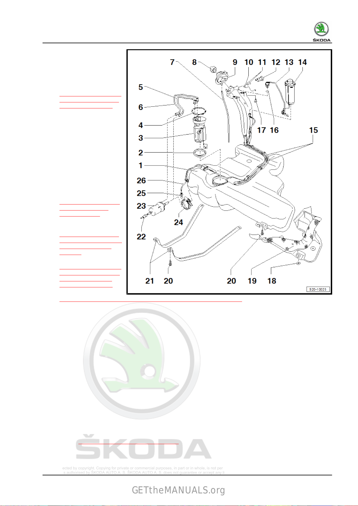
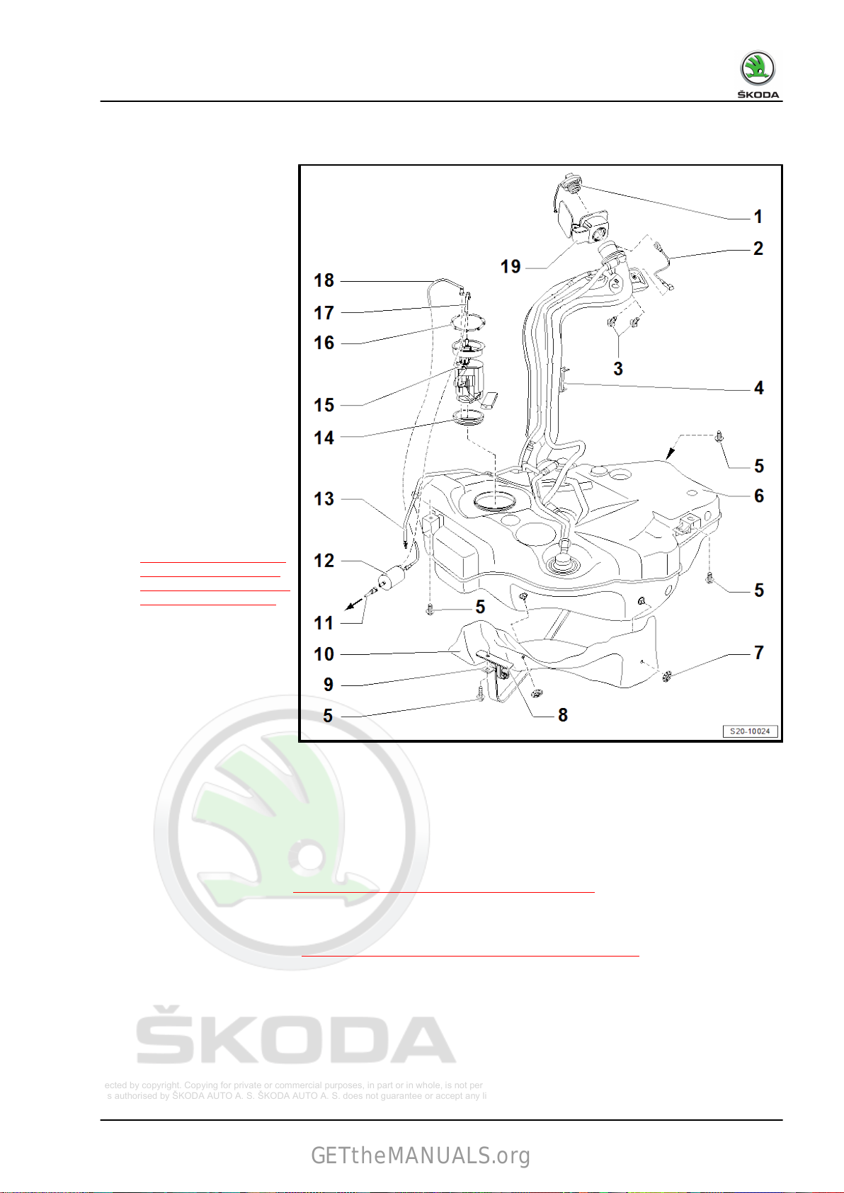
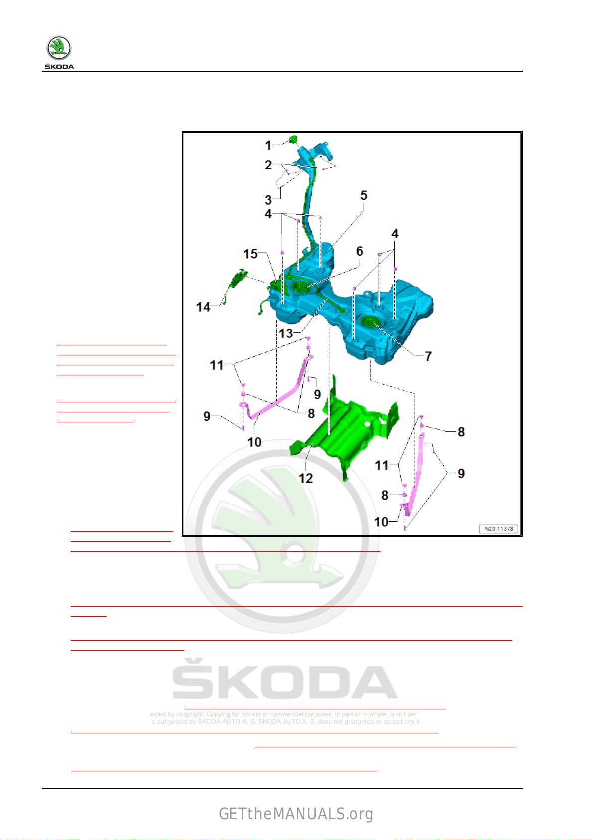
1.1.1 Summary of components - fuel tank, Rapid NH
8 Rep. gr.20 - Fuel supply system
Protected by copyright. Copying for private or commercial purposes, in part or in whole, is not permitted
unless authorised by ŠKODA AUTO A. S. ŠKODA AUTO A. S. does not guarantee or accept any liability
with respect to the correctness of information in this document. Copyright by ŠKODA AUTO A. S.
Karoq 2018 ➤ , Kodiaq 2017 ➤ , Kodiaq 2019 ➤ , Octavia III 2013 ➤ , Oc ...
GETtheMANUALS.org
Fuel system - Petrol engines - Edition 12.2018
1 - Fuel tank
❑
support with engine/
gearbox jack V.A.G 1383A- when re‐
moving
❑ Removing and installing
⇒ “1.2.1 Removing and
installing the fuel tank,
Rapid NH”, page 24
2 - Sealing ring
❑
replace if damaged
3 - Fuel pump - G6-
❑ In the event of a fuel
pump with integrated
fuel filter, the fuel filter
cannot be replaced indi‐
vidually
❑ Checking fuel pump
electrics ⇒ Vehicle diag‐
nostic tester
❑ Fitting position
⇒ Fig. ““Fitting location
of the fuel delivery
unit”“ , page 10
❑
Summary of compo‐
nents
⇒ “2.1 Assembly over‐
view - fuel delivery unit,
fuel gauge sender”,
page 81
❑ Removing
and installing
⇒ “2.3.2 Removing and
installing fuel pump for
pre-delivery G6 G6,
Rapid NH”, page 97
❑
inspecting fuel pump
⇒ “7.1 Checking the fuel system pressurisation pump G6 ”, page 140
4 - Lock ring
❑
110 Nm
5 - Return-flow line
❑ not in vehicles with fuel filter in flange of the fuel delivery unit
6 - Feed line
❑ black
7 - Overflow hose
8 - Screw cap
9 - Fuel tank lid unit
❑ with rubber bowl
10 - Earth connection
11 - O-ring
❑ Replace after disassembly
12 - Vent valve
❑ Check
⇒ Fig. ““Inspect vent valve”“ , page 11
13 - Gravity valve
❑
to remove, unclip valve and lift up and out of the filler neck
1. Fuel tank 9
Protected by copyright. Copying for private or commercial purposes, in part or in whole, is not permitted
unless authorised by ŠKODA AUTO A. S. ŠKODA AUTO A. S. does not guarantee or accept any liability
with respect to the correctness of information in this document. Copyright by ŠKODA AUTO A. S.
Karoq 2018 ➤ , Kodiaq 2017 ➤ , Kodiaq 2019 ➤ , Octavia III 2013 ➤ , Oc ...
GETtheMANUALS.org
Fuel system - Petrol engines - Edition 12.2018
❑ inspect valve for blockage:
❑
Valve open vertically
❑ Valve tilted 45°: closed
14 - Activated charcoal filter
❑ Summary of components of activated charcoal filter system
⇒ “5.1.3 Summary of components - activated charcoal filter system, Rapid NH”, page 125
❑
Checking the fuel tank venting
15 - Vent line
16 - O-ring
❑
Replace after disassembly
17 - Screw
❑ 10 Nm
18 - Circlip
19 - Heat shield
❑ for fuel tank
20 - Screw
❑ Replace after disassembly
❑ 25 Nm
21 - Straps
❑ pay attention to different lengths
22 - fuel feed line
❑ black
23 - Fuel filter
❑ not in vehicles with fuel filter in flange of the fuel delivery unit
❑ Summary of components
24 - Screw clamp
❑
not in vehicles with fuel filter in flange of the fuel delivery unit
25 - Vent line
❑ to solenoid valve 1 for activated charcoal filter in engine compartment
26 - Vent line
❑ between activated charcoal filter Pos. 14 and vent line Pos. 25
⇒ “5.3.3 Checking the fuel tank venting, Rapid NH”, page 132
⇒ “4.1 Summary of components - fuel filter”, page 121
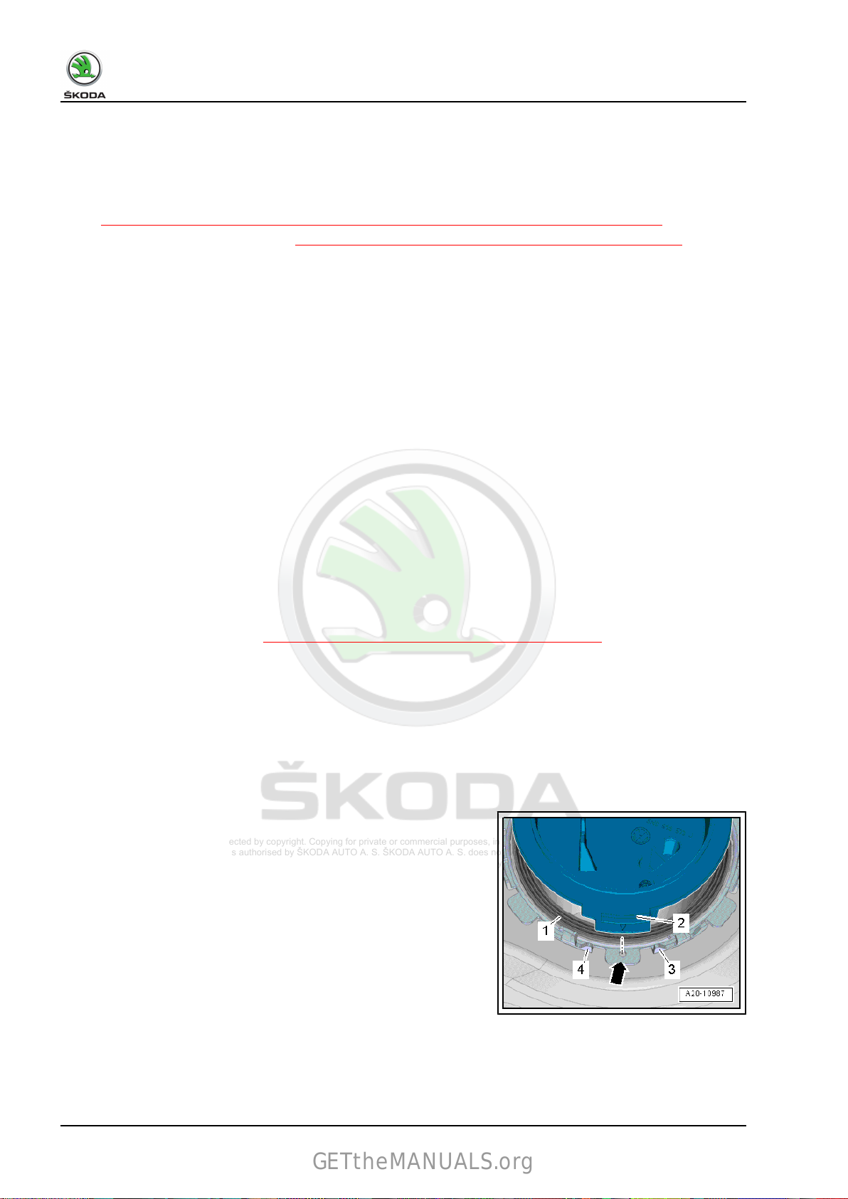
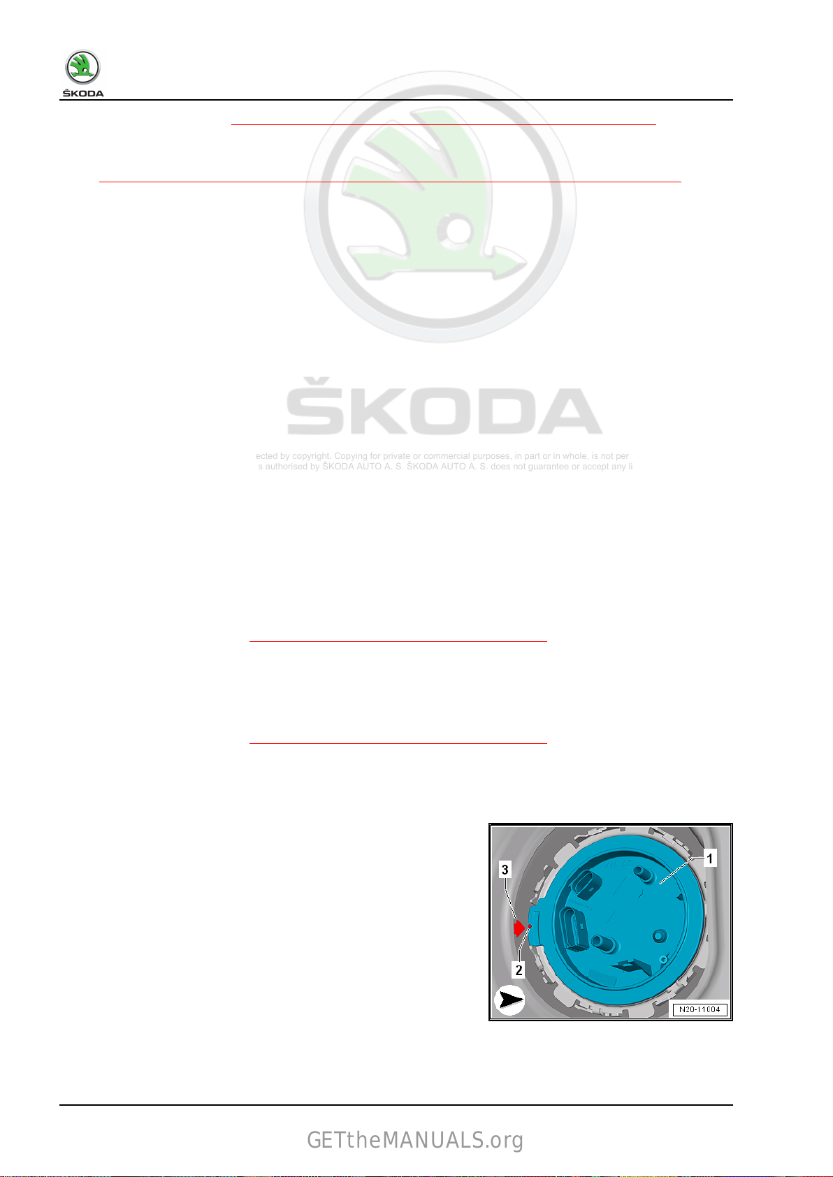
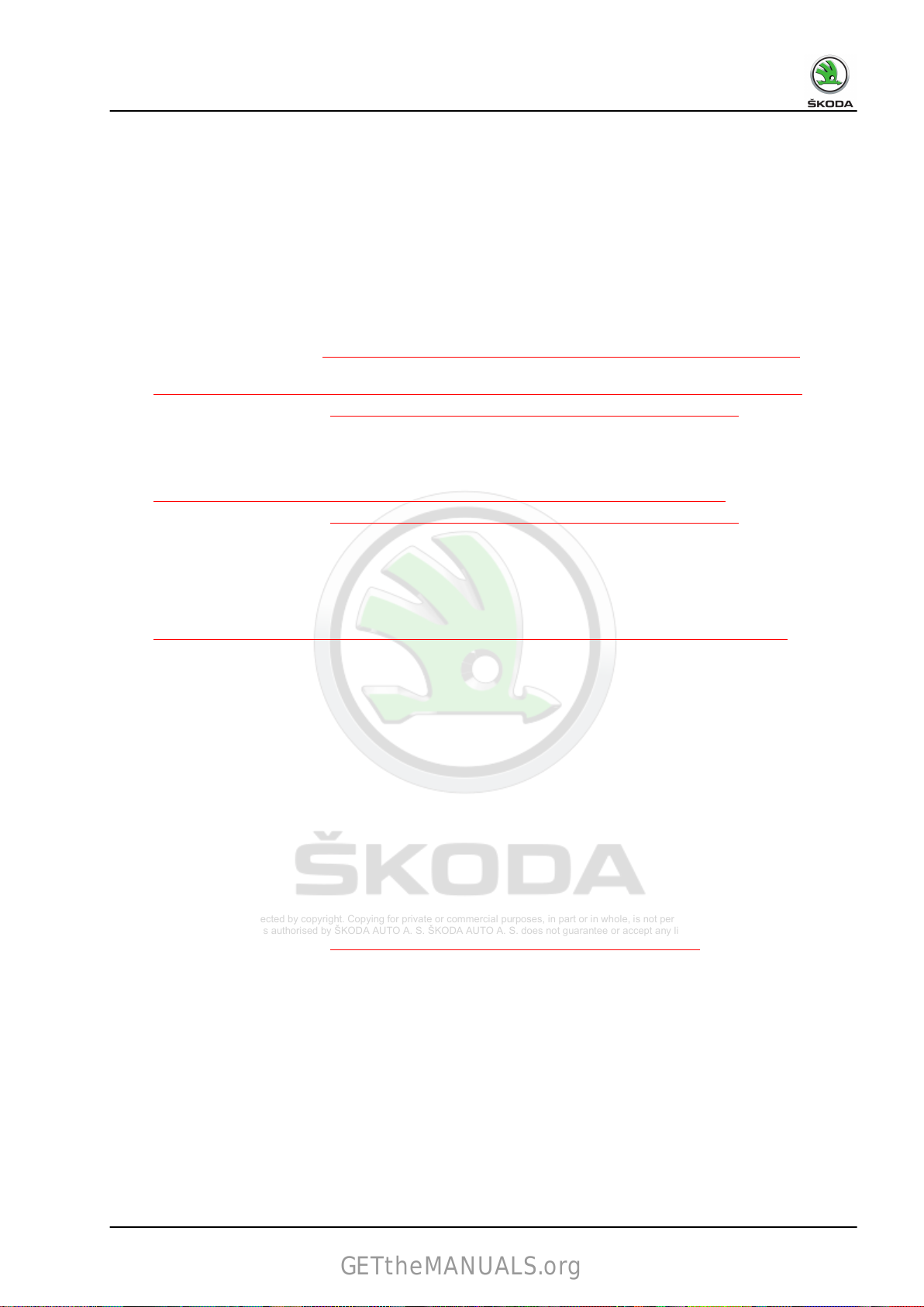
Fitting location of the fuel delivery unit
• Clutch -2- on the fuel delivery unit closing flange must point to
opening -arrow- and be between tabs -3- and -4- on the fuel
tank locking ring.
10 Rep. gr.20 - Fuel supply system
Protected by copyright. Copying for private or commercial purposes, in part or in whole, is not permitted
unless authorised by ŠKODA AUTO A. S. ŠKODA AUTO A. S. does not guarantee or accept any liability
with respect to the correctness of information in this document. Copyright by ŠKODA AUTO A. S.
Karoq 2018 ➤ , Kodiaq 2017 ➤ , Kodiaq 2019 ➤ , Octavia III 2013 ➤ , Oc ...
GETtheMANUALS.org
Fuel system - Petrol engines - Edition 12.2018
Inspect vent valve
If the lever is in the rest position, the air bleed valve must be
closed.
If the lever is pressed in the -direction
is then opened.
Note
of arrow-, the air bleed valve
Before installation of the vent valve unscrew the cap from the filler
neck.
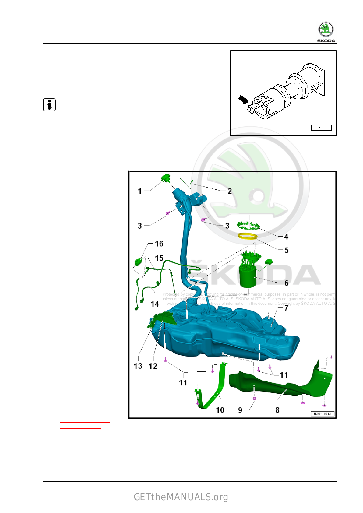
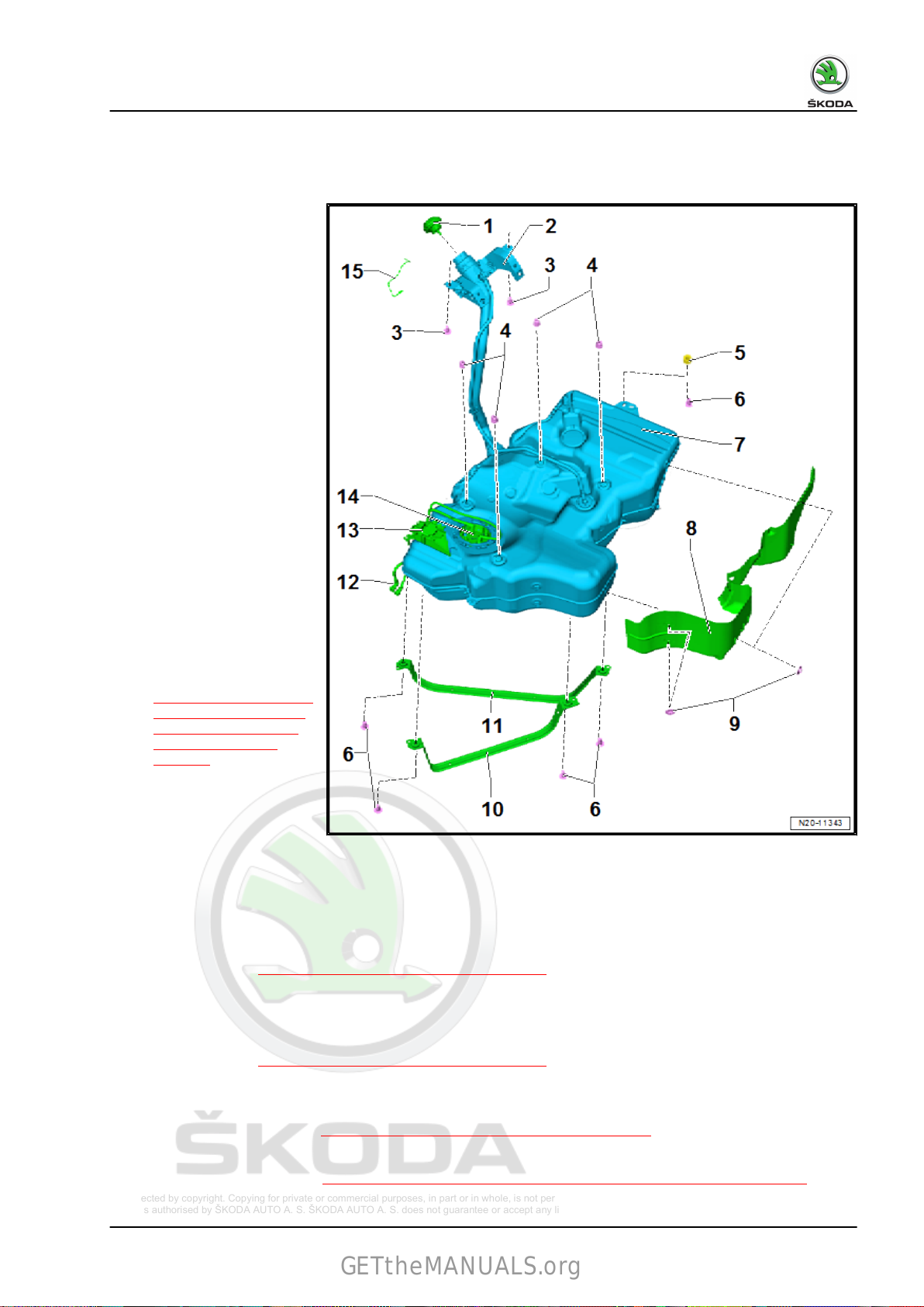
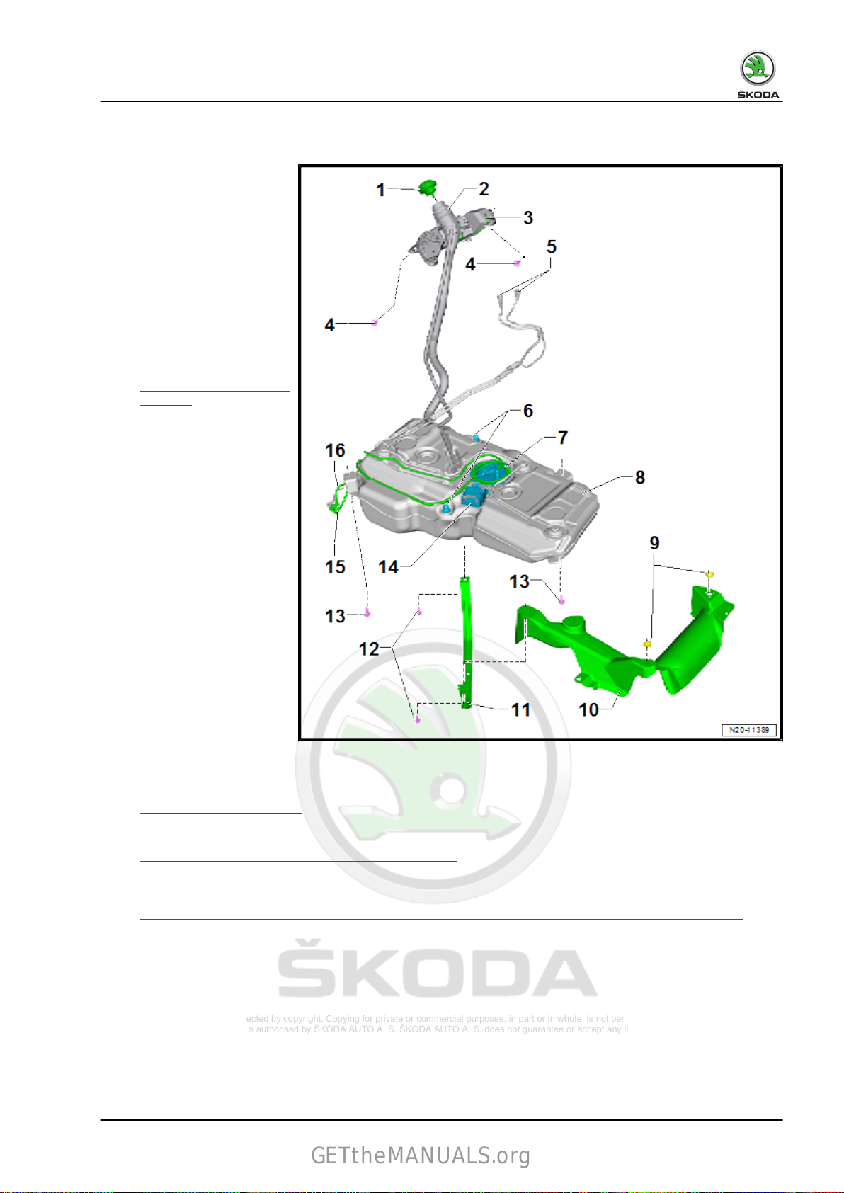
1.1.2 Summary of components - fuel tank, Octavia III, vehicles with front-wheel drive
1 - Screw cap
❑ screw
❑ attached to the fuel tank
2 - Earth connection
❑ for fuel filler neck
❑ for discharging the elec‐
3 - Screw
❑
❑ 8 Nm + 90°
4 - Lock ring
❑ 110 Nm
5 - Sealing ring
❑ Replace after disas‐
❑ install when dry
6 - Fuel pump - G6-
❑ with integrated fuel filter,
❑ Checking fuel pump
❑ Fitting position
❑
❑
in until there is an
audible click
lid unit with anti-loss
washer
trostatic charge
⇒ Fig. ““Earth connec‐
tion for fuel filler neck”“ ,
page 31
Replace after disas‐
sembly
sembly
the fuel filter cannot be
replaced individually
electrics ⇒ Vehicle diag‐
nostic tester
⇒ Fig. ““Fitting location
of the fuel delivery
unit”“ , page 12
Summary of components
⇒ “2.1.1 Assembly overview - Fuel pump for pre- feed G6 , Vehicles with front-wheel drive and with fuel
filter in the flange of the fuel delivery unit”, page 81
Removing and installing
⇒ “2.3.1 Fuel pump for pre-delivery G6 Removing and installing front-wheel drive vehicles, Octavia III,
Yeti”, page 93
1. Fuel tank 11
Protected by copyright. Copying for private or commercial purposes, in part or in whole, is not permitted
unless authorised by ŠKODA AUTO A. S. ŠKODA AUTO A. S. does not guarantee or accept any liability
with respect to the correctness of information in this document. Copyright by ŠKODA AUTO A. S.
Karoq 2018 ➤ , Kodiaq 2017 ➤ , Kodiaq 2019 ➤ , Octavia III 2013 ➤ , Oc ...
GETtheMANUALS.org
Fuel system - Petrol engines - Edition 12.2018
❑ inspecting fuel pump ⇒ “7.1 Checking the fuel system pressurisation pump G6 ”, page 140
7 - Fuel tank
❑
Removing and installing
⇒ “1.2.2 Removing and installing fuel tank Octavia III, vehicles with front-wheel drive”, page 27
8 - Heat shield
❑
for fuel tank
9 - Shield locking mechanism
❑ for heat shield
❑ Qty. 4
10 - Tensioning strap
❑ mark installed position before removing
❑ check correct fitting
11 - Screw
❑ Replace after disassembly
❑ 20 Nm + 90°
12 - Mounting bracket
❑ For fuel pump control unit -J538-
13 - Mounting bracket
❑ for vehicles with auxiliary heating
❑ for dosing pump -V54❑ pay attention to correct fit of the dosing pump in the holder
14 - Fuel line
❑ to the engine
❑ pushed into the fuel tank
❑ do not kink
❑ disconnect and connect
15 - Fuel line
❑
for vehicles with auxiliary heating
❑ to the dosing pump -V54❑ do not kink
❑ disconnect and connect
16 - Dosing pump -V54-
❑
for vehicles with auxiliary heating
⇒ “3.1 Separating push-on couplings”, page 117
⇒ “3.1 Separating push-on couplings”, page 117
Fitting location of the fuel delivery unit
• The marking -2- on the closing flange of the fuel pump -1- must
be located opposite to the arrow -3- on the fuel tank.
12 Rep. gr.20 - Fuel supply system
Protected by copyright. Copying for private or commercial purposes, in part or in whole, is not permitted
unless authorised by ŠKODA AUTO A. S. ŠKODA AUTO A. S. does not guarantee or accept any liability
with respect to the correctness of information in this document. Copyright by ŠKODA AUTO A. S.
Karoq 2018 ➤ , Kodiaq 2017 ➤ , Kodiaq 2019 ➤ , Octavia III 2013 ➤ , Oc ...
GETtheMANUALS.org
Fuel system - Petrol engines - Edition 12.2018
1.1.3 Summary of components -fuel tank, Yeti, front-wheel drive vehicles
1 - Screw cap
❑ screw
❑ attached to the fuel tank
2 - Earth connection
❑ for fuel filler neck
❑ check for firm seating
3 - Screw
❑ Replace after disas‐
❑ 11 Nm
4 - Wiring
5 - Screw
❑ Replace after disas‐
❑ 25 Nm
6 - Fuel tank
❑ Removing and installing
7 - Circlip
8
- Bracket for the exhaust sys‐
tem
9 - Tensioning strap
❑ mark installed position
❑ check correct fitting
10 - Heat shield
❑ for fuel tank
11 - fuel feed line
❑ to the engine
❑ pushed into the fuel tank
❑ do not kink
❑ disconnect and connect
12 - Fuel filter
❑
❑ Summary of components
13 - Vent line
❑
❑ check for firm seating
14 - Sealing ring
❑ Replace after disassembly
❑ install when dry
in until there is an
audible click
lid unit with anti-loss
washer
sembly
sembly
⇒ “1.2.3 Removing and
installing the fuel tank,
Yeti - vehicles with frontwheel drive”, page 31
before removing
⇒ “3.1 Separating push-on couplings”, page 117
Fitting position: arrow points in direction of flow
⇒ “4.1 Summary of components - fuel filter”, page 121
pushed into the fuel tank
1. Fuel tank 13
Protected by copyright. Copying for private or commercial purposes, in part or in whole, is not permitted
unless authorised by ŠKODA AUTO A. S. ŠKODA AUTO A. S. does not guarantee or accept any liability
with respect to the correctness of information in this document. Copyright by ŠKODA AUTO A. S.
Karoq 2018 ➤ , Kodiaq 2017 ➤ , Kodiaq 2019 ➤ , Octavia III 2013 ➤ , Oc ...
GETtheMANUALS.org
Fuel system - Petrol engines - Edition 12.2018
15 - Fuel pump - G6-
❑
with fuel gauge sender - G-
❑ Removing and installing
⇒ “2.3.1 Fuel pump for pre-delivery G6 Removing and installing front-wheel drive vehicles, Octavia III,
Yeti”, page 93
❑
inspecting fuel pump
❑
Summary of components
❑
Fitting position
❑
Removing and installing the fuel gauge sender - G-
⇒ “2.4.1 Removing and installing the fuel gauge sender display G , vehicles with front-wheel drive”, page
113
❑
disconnect and connect
❑
Clean strainer if dirty
16 - Lock ring
❑ 110 Nm
17 - fuel feed line
❑ black
❑ pushed into the fuel tank
❑ check for firm seating
18 - Fuel return-flow line
❑ blue
❑ pushed into the fuel tank
❑ check for firm seating
19 - Fuel tank lid unit
❑ removing and installing ⇒ general body repairs, exterior; Rep. gr. 55 ; Fuel tank lid unit; installing and
removing fuel tank lid unit.
⇒ “7.1 Checking the fuel system pressurisation pump G6 ”, page 140
⇒ “2.1 Assembly overview - fuel delivery unit, fuel gauge sender”, page 81
⇒ Fig. ““Fitting location of the fuel delivery unit”“ , page 14
⇒ “3.1 Separating push-on couplings”, page 117
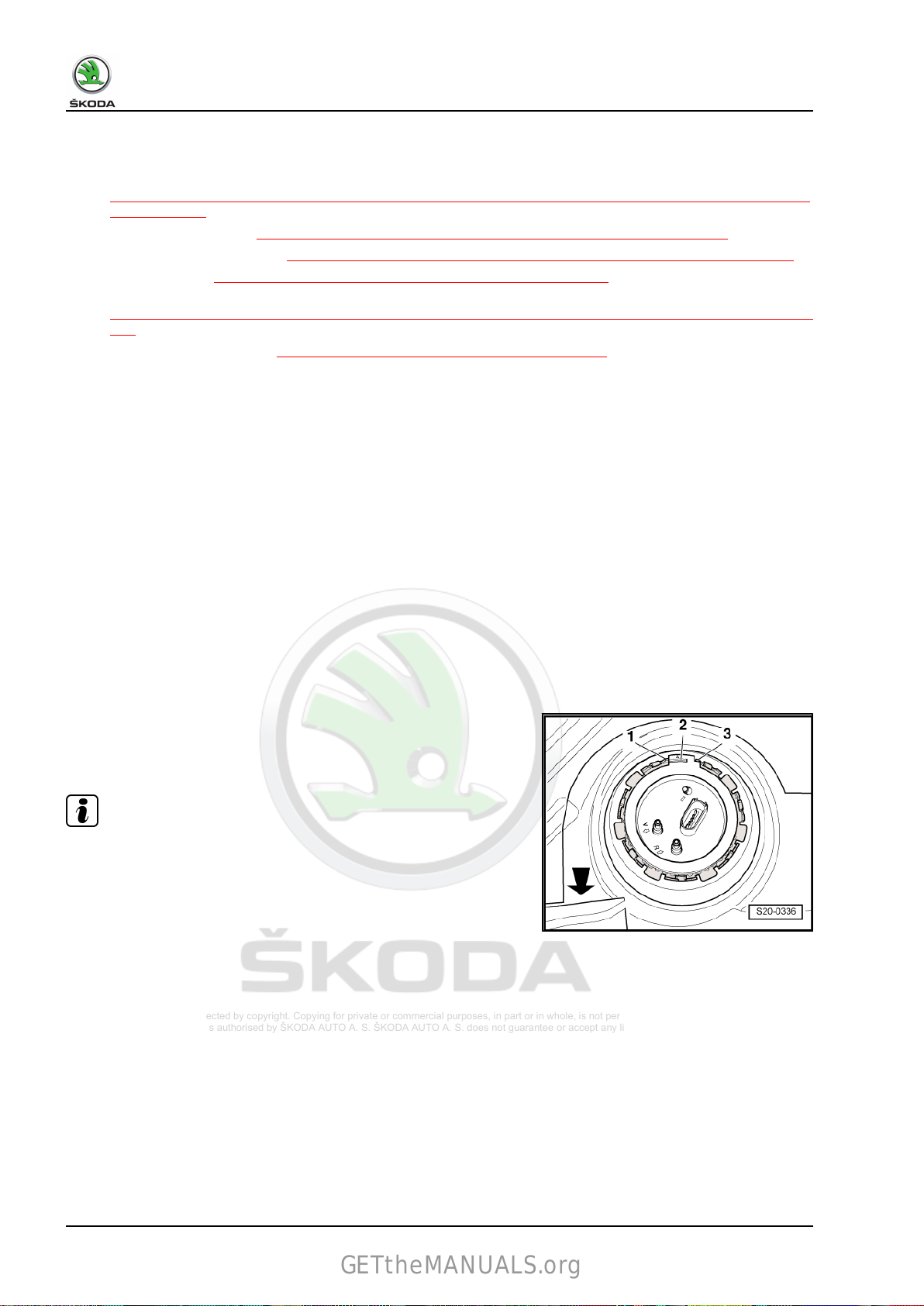
Fitting location of the fuel delivery unit
• The peg -2- on the fuel delivery unit must be between the pegs
-1- and -3-.
Note
♦
The -arrow- shows the direction of travel.
♦
The fuel delivery unit can only be installed in this position.
14 Rep. gr.20 - Fuel supply system
Protected by copyright. Copying for private or commercial purposes, in part or in whole, is not permitted
unless authorised by ŠKODA AUTO A. S. ŠKODA AUTO A. S. does not guarantee or accept any liability
with respect to the correctness of information in this document. Copyright by ŠKODA AUTO A. S.
Karoq 2018 ➤ , Kodiaq 2017 ➤ , Kodiaq 2019 ➤ , Octavia III 2013 ➤ , Oc ...
GETtheMANUALS.org
Fuel system - Petrol engines - Edition 12.2018
1.1.4 Summary of components - fuel tank, Superb III, vehicles with front-wheel
drive
1 - Screw cap
❑ screw
❑ attached to the fuel tank
2 - Filler neck
3 - Screw
❑ Replace after disas‐
❑ 8 Nm + 90°
4 - Rubber buffer
❑ Qty. 4
❑ between fuel tank and
❑ check correct fitting
5 - Guide
6 - Screw
❑ Replace after disas‐
❑ 20 Nm + 90°
7 - Fuel tank
❑ Removing and installing
8 - Heat shield
❑
9 - Clamping system
❑ for heat shield
❑ Qty. 4
10 - Tensioning strap
❑ mark installed position before removing
❑ check correct fitting
❑ Fitting position
11 - Tensioning strap
❑
❑ check correct fitting
❑ Fitting position
12 - Connected fuel hoses
❑
❑ disconnect and connect
13 - Fuel pump control unit - J538-
❑
in until there is an
audible click
lid unit with anti-loss
washer
sembly
bodyshell
sembly
⇒ “1.2.4 Removing and
installing fuel tank Su‐
perb III, vehicles with
front-wheel drive”,
page 34
for fuel tank
⇒ Fig. ““Attaching the fuel tank”“ , page 16
mark installed position before removing
⇒ Fig. ““Attaching the fuel tank”“ , page 16
do not kink
⇒ “3.1 Separating push-on couplings”, page 117
Removing and installing
⇒ “7.2 Removing and installing fuel pump control unit J538 ”, page 170
1. Fuel tank 15
Protected by copyright. Copying for private or commercial purposes, in part or in whole, is not permitted
unless authorised by ŠKODA AUTO A. S. ŠKODA AUTO A. S. does not guarantee or accept any liability
with respect to the correctness of information in this document. Copyright by ŠKODA AUTO A. S.
Karoq 2018 ➤ , Kodiaq 2017 ➤ , Kodiaq 2019 ➤ , Octavia III 2013 ➤ , Oc ...
GETtheMANUALS.org
Fuel system - Petrol engines - Edition 12.2018
14 - Fuel pump - G6-
❑
with integrated fuel filter, the fuel filter cannot be replaced individually
❑ Removing and installing
⇒ “2.3.3 Fuel pump for pre-delivery G6 Removing and installing front-wheel drive vehicles, Superb III,
Karoq, Kodiaq”, page 100
❑
Summary of components
⇒ “2.1.1 Assembly overview - Fuel pump for pre- feed G6 , Vehicles with front-wheel drive and with fuel
filter in the flange of the fuel delivery unit”, page 81
15 - Earth connection
❑
for fuel filler neck
❑ for discharging the electrostatic charge
Attaching the fuel tank
1 - Tensioning strap for fuel tank
2 - Screw with washer
3 - Rubber holder
4 - guide bushing
⇒ Fig. ““Earth connection for fuel filler neck”“ , page 40
16 Rep. gr.20 - Fuel supply system
Protected by copyright. Copying for private or commercial purposes, in part or in whole, is not permitted
unless authorised by ŠKODA AUTO A. S. ŠKODA AUTO A. S. does not guarantee or accept any liability
with respect to the correctness of information in this document. Copyright by ŠKODA AUTO A. S.
Karoq 2018 ➤ , Kodiaq 2017 ➤ , Kodiaq 2019 ➤ , Octavia III 2013 ➤ , Oc ...
GETtheMANUALS.org
Fuel system - Petrol engines - Edition 12.2018
1.1.5 Summary of components -fuel tank, Kodiaq, front-wheel drive vehicles
1 - Screw cap
❑ screw
❑ attached to the fuel tank
2 - Filler neck
3 - Earth connection
❑ for fuel filler neck
❑ for discharging the elec‐
4 - Screw
❑
❑ 8 Nm + 90°
5 - Vent line
❑ to activated charcoal fil‐
❑ pushed into the fuel tank
❑ do not kink
6 - Rubber buffer
❑ Qty. 4
❑ between fuel tank and
❑ check correct fitting
7 - Fuel pump - G6-
❑ with integrated fuel filter,
❑ Removing and installing
❑
8 - Fuel tank
❑
9 - Clamping system
❑
10 - Heat shield
❑ for fuel tank
11 - Tensioning strap
❑ check correct fitting
12 - Screw
❑ Replace after disassembly
in until there is an
audible click
lid unit with anti-loss
washer
trostatic charge
⇒ Fig. ““Earth connec‐
tion for fuel filler neck”“ ,
page 47
Replace after disas‐
sembly
ter solenoid valve 1 N80- and to activated
charcoal filter
bodyshell
the fuel filter cannot be replaced individually
⇒ “2.3.3 Fuel pump for pre-delivery G6 Removing and installing front-wheel drive vehicles, Superb III,
Karoq, Kodiaq”, page 100
Summary of components
⇒ “2.1.1 Assembly overview - Fuel pump for pre- feed G6 , Vehicles with front-wheel drive and with fuel
filter in the flange of the fuel delivery unit”, page 81
Removing and installing
⇒ “1.2.5 Removing and installing the fuel tank, Kodiaq - vehicles with front-wheel drive”, page 40
for heat shield
1. Fuel tank 17
Protected by copyright. Copying for private or commercial purposes, in part or in whole, is not permitted
unless authorised by ŠKODA AUTO A. S. ŠKODA AUTO A. S. does not guarantee or accept any liability
with respect to the correctness of information in this document. Copyright by ŠKODA AUTO A. S.
Karoq 2018 ➤ , Kodiaq 2017 ➤ , Kodiaq 2019 ➤ , Octavia III 2013 ➤ , Oc ...
GETtheMANUALS.org
Fuel system - Petrol engines - Edition 12.2018
❑ 20 Nm + 90°
13 - Screw
❑
Replace after disassembly
❑ 20 Nm + 90°
14 - Mounting bracket
❑ Fuel pump control unit - J538❑ Removing and installing fuel pump control unit - J538-
⇒ “7.2 Removing and installing fuel pump control unit J538 ”, page 170
15 - Fuel line
❑
Vehicles fitted with auxiliary heating
❑ for dosing pump - V54❑ do not kink
16 - Fuel line
❑ to the engine
❑ pushed into the fuel tank
❑ do not kink
1.1.6 Summary of components -fuel tank, Karoq, vehicles with front-wheel drive
1 - Screw cap
❑ screw in until there is an
audible click
❑ attached to the fuel tank
lid unit with anti-loss
washer
2 - Earth connection
❑ for fuel filler neck
❑ for discharging the elec‐
trostatic charge
⇒ Fig. ““Earth connec‐
tion for fuel filler neck”“ ,
page 52
3 - Screw
❑
Replace after disas‐
sembly
❑ 8 Nm + 90°
4 - Lock ring
❑ use wrench - T10202- or
-T30101 (3087)- for
loosening and tighten‐
ing
❑ 110 Nm
5 - Sealing ring
❑ Replace after disas‐
sembly
❑ install when dry
6 - Fuel pump - G6-
❑ with integrated fuel filter,
the fuel filter cannot be
replaced individually
❑ Removing and installing
⇒ “2.3.3 Fuel pump for
18 Rep. gr.20 - Fuel supply system
Protected by copyright. Copying for private or commercial purposes, in part or in whole, is not permitted
unless authorised by ŠKODA AUTO A. S. ŠKODA AUTO A. S. does not guarantee or accept any liability
with respect to the correctness of information in this document. Copyright by ŠKODA AUTO A. S.
Karoq 2018 ➤ , Kodiaq 2017 ➤ , Kodiaq 2019 ➤ , Octavia III 2013 ➤ , Oc ...
GETtheMANUALS.org
Fuel system - Petrol engines - Edition 12.2018
pre-delivery G6 Removing and installing front-wheel drive vehicles, Superb III, Karoq, Kodiaq”,
page 100
❑
Summary of components
⇒ “2.1.1 Assembly overview - Fuel pump for pre- feed G6 , Vehicles with front-wheel drive and with fuel
filter in the flange of the fuel delivery unit”, page 81
7 - Fuel tank
❑
Removing and installing
⇒ “1.2.6 Removing and installing the fuel tank, Karoq - vehicles with front-wheel drive”, page 47
8 - Heat shield
❑
for fuel tank
9 - Clamping system
❑ for heat shield
10 - Tensioning strap
❑ check correct fitting
11 - Screw
❑ Replace after disassembly
❑ 20 Nm + 90°
12 - Fuel pump control unit - J538-
❑ Removing and installing
⇒ “7.2 Removing and installing fuel pump control unit J538 ”, page 170
13 - Fuel line
❑
to the engine
❑ do not kink
❑ disconnect and connect
⇒ “3.1 Separating push-on couplings”, page 117
14 - Vent line
❑
to activated charcoal filter solenoid valve 1 - N80- and to activated charcoal filter
❑ do not kink
15 - Vent line
❑ to the activated charcoal filter system
❑ do not kink
1. Fuel tank 19
Protected by copyright. Copying for private or commercial purposes, in part or in whole, is not permitted
unless authorised by ŠKODA AUTO A. S. ŠKODA AUTO A. S. does not guarantee or accept any liability
with respect to the correctness of information in this document. Copyright by ŠKODA AUTO A. S.
Karoq 2018 ➤ , Kodiaq 2017 ➤ , Kodiaq 2019 ➤ , Octavia III 2013 ➤ , Oc ...
GETtheMANUALS.org
Fuel system - Petrol engines - Edition 12.2018
1.1.7 Assembly overview - fuel tank, Octavia III, Superb III, Kodiaq, Karoq, fourwheel drive vehicles
1 - Screw cap
❑ screw
❑ attached to the fuel tank
2 - Screw
❑ Replace after disas‐
❑ 8 Nm + 90°
3 - Earth connection
❑ for fuel filler neck
❑ for discharging the elec‐
♦ For Superb III, Kodiaq ve‐
hicles
⇒ Fig. ““Earth connection
for fuel filler support for Oc‐
tavia III, Superb III, Kodiaq
vehicles”“ , page 58
♦
For the Karoq vehicles
⇒ Fig. ““Ground connection
for fuel filler neck vehicles
Karoq”“ , page 59
4 - Rubber buffer
❑
❑ between fuel tank and
❑ check correct fitting
5 - Fuel tank
❑ Removing and installing
6 - Fuel pump - G6-
❑
❑ Summary of components
❑
7 - Left fuel pump
❑
❑ for fuel gauge transmitter 2 - G169❑ Summary of components
❑
❑
❑
in until there is an
audible click
lid unit with anti-loss
washer
sembly
trostatic charge:
Qty. 6
bodyshell
⇒ “1.2.7 Removing and
installing fuel tank, Oc‐
tavia III, Superb III, Kodiaq, Karoq, four-wheel drive vehicles”, page 52
with integrated fuel filter, the fuel filter cannot be replaced individually
⇒ “2.1.3 Summary of components - fuel system pressurisation pump G6 , vehicles with four-wheel drive”,
page 85
Removing and installing
⇒ “2.3.4 Fuel pump for pre-delivery G6 Removing and installing, all-wheel drive vehicles, Superb III,
Karoq, Kodiaq”, page 104
with suction spray pump
Removing and installing
⇒ “2.3.6 Removing and installing the fuel pump closing flange on the left”, page 111
Removing and installing suction jet pump
Removing and installing fuel gauge sender 2 - G169-
⇒ “2.5 Removing and installing fuel gauge sender 2 G169 ”, page 116
⇒ “2.1.5 Summary of components - left fuel pump”, page 89
⇒ “7.4 Removing and installing suction jet pump”, page 172
20 Rep. gr.20 - Fuel supply system

Protected by copyright. Copying for private or commercial purposes, in part or in whole, is not permitted
unless authorised by ŠKODA AUTO A. S. ŠKODA AUTO A. S. does not guarantee or accept any liability
with respect to the correctness of information in this document. Copyright by ŠKODA AUTO A. S.
Karoq 2018 ➤ , Kodiaq 2017 ➤ , Kodiaq 2019 ➤ , Octavia III 2013 ➤ , Oc ...
GETtheMANUALS.org
8 - Rubber buffer
9 - Screw
❑
Replace after disassembly
❑ 20 Nm + 90°
10 - Tensioning strap
❑ mark installed position before removing
❑ check correct fitting
❑ Securing the fuel tank
⇒ Fig. ““Attaching the fuel tank”“ , page 16
11 - Guides
12 - Heat shield
❑
for fuel tank
13 - Vent line
14 - Dosing pump - V54-
❑ fir auxiliary heating
15 - Mounting bracket
❑ Fuel pump control unit - J538❑ Removing and installing
⇒ “7.2 Removing and installing fuel pump control unit J538 ”, page 170
Fuel system - Petrol engines - Edition 12.2018
1. Fuel tank 21

Protected by copyright. Copying for private or commercial purposes, in part or in whole, is not permitted
unless authorised by ŠKODA AUTO A. S. ŠKODA AUTO A. S. does not guarantee or accept any liability
with respect to the correctness of information in this document. Copyright by ŠKODA AUTO A. S.
Karoq 2018 ➤ , Kodiaq 2017 ➤ , Kodiaq 2019 ➤ , Octavia III 2013 ➤ , Oc ...
GETtheMANUALS.org
Fuel system - Petrol engines - Edition 12.2018
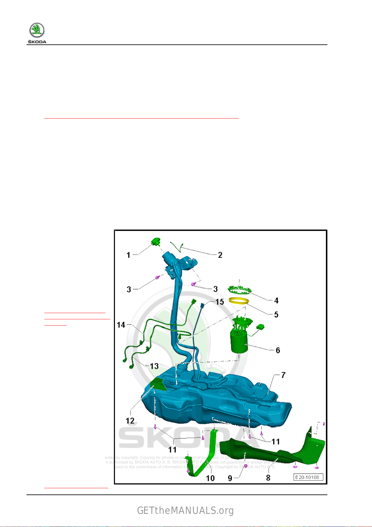
1.1.8 Summary of components -fuel tank, Yeti, four-wheel drive vehicles
1 - fuel feed line
❑
black
❑ check for firm seating
2 - Fuel return-flow line
❑ blue
❑ check for firm seating
3 - Sealing ring
❑ replace
❑ insert dry into the open‐
ing of the fuel tank
❑ only moisten the inner
seal of the flange with
fuel for fitting purposes
4 - Fuel pump
❑ Removing and installing
⇒ “2.3.5 Removing and
installing fuel system
pressurisation pump
G6 , vehicles with fourwheel drive, Yeti”,
page 107
❑
inspecting fuel pump
⇒ “7.1 Checking the fuel
system pressurisation
pump G6 ”, page 140
❑ note
❑ with
❑ Summary of components
❑
❑
5 - Lock ring
❑ 110 Nm
6 - Fuel pump control unit - J538-
❑ after replacing, adapt the engine control unit - J623- to the fuel pump control unit - J538- ⇒ Vehicle
7 - Screw cap
❑ replace if damaged
8 - Fixing screw
9 - Fuel tank lid unit
❑ with rubber bowl
❑ removing and installing ⇒ general body repairs, exterior; Rep. gr. 55 ; Fuel tank lid unit; installing and
the correct installa‐
tion position in the fuel
tank
⇒ Fig. ““Fitting position
of the fuel delivery unit
and the fuel gauge
sender 2 -G169- ”“ ,
page 24
fuel gauge sender -
G-
Removing and installing the fuel gauge sender - G-
⇒ “2.4.1 Removing and installing the fuel gauge sender display G , vehicles with front-wheel drive”, page
113
Clean strainer if dirty
diagnostic tester
removing fuel tank lid unit.
⇒ “2.1 Assembly overview - fuel delivery unit, fuel gauge sender”, page 81
22 Rep. gr.20 - Fuel supply system
Protected by copyright. Copying for private or commercial purposes, in part or in whole, is not permitted
unless authorised by ŠKODA AUTO A. S. ŠKODA AUTO A. S. does not guarantee or accept any liability
with respect to the correctness of information in this document. Copyright by ŠKODA AUTO A. S.
Karoq 2018 ➤ , Kodiaq 2017 ➤ , Kodiaq 2019 ➤ , Octavia III 2013 ➤ , Oc ...
GETtheMANUALS.org
Fuel system - Petrol engines - Edition 12.2018
10 - Earth connection
❑
check for firm seating
11 - Screw
❑ 11 Nm
12 - Tank ventilation
13 - Plug connection
❑ Fuel gauge transmitter 2 - G16914 - Fuel gauge transmitter 2 - G169-
❑ with suction jet pump integrated in the left fuel pump
❑ Removing and installing
❑
note the correct installation position in the fuel tank
⇒ “2.5 Removing and installing fuel gauge sender 2 G169 ”, page 116
⇒ Fig. ““Fitting position of the fuel delivery unit and the fuel gauge sender 2 -G169- ”“ , page 24
❑
Summary of components
⇒ “2.1.5 Summary of components - left fuel pump”, page 89
15 - Suction spray pump
❑
with fuel gauge transmitter 2 - G169- integrated into the fuel pump on the left
❑ Removing and installing
⇒ “2.3.6 Removing and installing the fuel pump closing flange on the left”, page 111
❑
Summary of components
⇒ “2.1.5 Summary of components - left fuel pump”, page 89
16 - Tank ventilation
17 - Vent line
18 - Fuel tank
❑
Removing and installing
⇒ “1.2.8 Removing and installing the fuel tank, Yeti - vehicles with four-wheel drive”, page 59
19 - Tensioning strap
❑
Check fitting position
20 - Screw
❑ Replace after disassembly
❑ 25 Nm
21 - Screw
❑ 23 Nm
22 - Cover plate
❑ riveted together with hanger of exhaust system
23 - Screw
❑ 3 Nm
24 - Fuel filter
❑ Summary of components
⇒ “4.1 Summary of components - fuel filter”, page 121
25 - Vent line
❑
Clipped onto side of fuel tank.
❑ check for firm seating
1. Fuel tank 23
Protected by copyright. Copying for private or commercial purposes, in part or in whole, is not permitted
unless authorised by ŠKODA AUTO A. S. ŠKODA AUTO A. S. does not guarantee or accept any liability
with respect to the correctness of information in this document. Copyright by ŠKODA AUTO A. S.
Karoq 2018 ➤ , Kodiaq 2017 ➤ , Kodiaq 2019 ➤ , Octavia III 2013 ➤ , Oc ...
GETtheMANUALS.org
Fuel system - Petrol engines - Edition 12.2018
Fitting position of the fuel delivery unit and the fuel gauge sender
2 - G169-
Marking on the flange must be aligned with marking on the fuel
tank -arrows-.
Note
The arrows on the fuel tank are hardly visible because of the floor
panel.
1.2 Removing and installing the fuel tank
⇒ “1.2.1 Removing and installing the fuel tank, Rapid NH”,
page 24
⇒ “1.2.2 Removing and installing fuel tank Octavia III, vehicles
with front-wheel drive”, page 27
⇒ “1.2.3 Removing and installing the fuel tank, Yeti - vehicles with
front-wheel drive”, page 31
⇒ “1.2.4 Removing and installing fuel tank Superb III, vehicles with
front-wheel drive”, page 34
⇒ “1.2.5 Removing and installing the fuel tank, Kodiaq - vehicles
with front-wheel drive”, page 40
⇒ “1.2.6 Removing and installing the fuel tank, Karoq - vehicles
with front-wheel drive”, page 47
⇒ “1.2.7 Removing and installing fuel tank, Octavia III, Superb III,
Kodiaq, Karoq, four-wheel drive vehicles”, page 52
⇒ “1.2.8 Removing and installing the fuel tank, Yeti - vehicles with
four-wheel drive”, page 59
1.2.1 Removing and installing the fuel tank, Rapid NH
Special tools and workshop equipment required
♦ Engine/gearbox jack , e.g. -V.A.G 1383A-
• The fuel tank must be empty for weight reasons when remov‐
ing it. If necessary, extract fuel from the fuel tank
⇒ “1.3 Drain the fuel tank”, page 64 .
Removing
Safety precautions when working on the fuel supply system
⇒ “2.1 Safety precautions when working on fuel supply system”,
page 4 .
Observe rules for cleanliness
⇒ “3.1 Cleanliness rules when working on the parking/auxiliary
heater and fuel system”, page 6 .
– Switch
key.
– Remove cover for fuel pump assembly opening
⇒ “2.2.1 Removing and installing cover of assembly opening,
Rapid NH, Yeti”, page 90 .
off ignition and all electrical loads, and pull out ignition
24 Rep. gr.20 - Fuel supply system
Protected by copyright. Copying for private or commercial purposes, in part or in whole, is not permitted
unless authorised by ŠKODA AUTO A. S. ŠKODA AUTO A. S. does not guarantee or accept any liability
with respect to the correctness of information in this document. Copyright by ŠKODA AUTO A. S.
Karoq 2018 ➤ , Kodiaq 2017 ➤ , Kodiaq 2019 ➤ , Octavia III 2013 ➤ , Oc ...
GETtheMANUALS.org
Fuel system - Petrol engines - Edition 12.2018
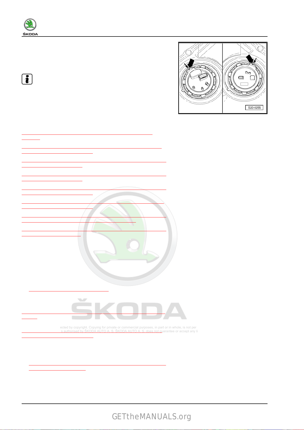
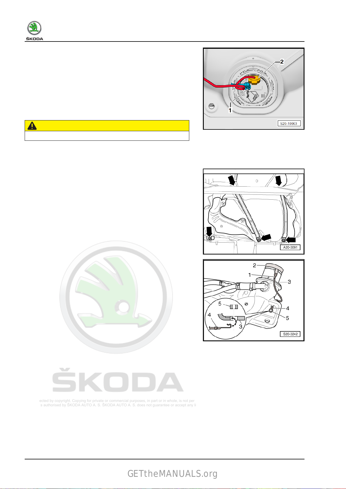
– Disconnect plug connection -arrow- at the closing flange.
– Open the fuel tank cap and clean around the fuel filler neck
-2-.
– Unscrew the cap -1- for the fuel filler neck.
Note
Close the opening of the fuel filler neck with a clean cloth so that
no dirt can penetrate.
– Remove the rear right wheelhouse liner ⇒ General body re‐
pairs, exterior; Rep. gr. 66 ; Wheelhouse liner; removing and
installing rear wheelhouse liner .
– Unscrew fixing screws on tank filler neck -arrows-.
– Remove both ventilation lines from activated charcoal filter
⇒ “5.1.3 Summary of components - activated charcoal filter
system, Rapid NH”, page 125 , Pos. 6 and 7.
– Remove rear axle ⇒ Chassis, axles, steering; Rep. gr. 42 ;
Rear axle; removing and installing rear axle .
– Remove centre and rear of exhaust system ⇒ Rep. gr. 26 ;
Exhaust pipes / exhaust; Remove and install centre and rear
section
of the exhaust system . ⇒ Rep. gr. 26 ; Exhaust pipes /
exhaust; Removing and installing rear silencer .
CAUTION
Risk of injury caused by fuel which is under high pressure.
Lay a clean cloth around the connection point and carefully slack‐
the connection point in order to relieve the pressure in the fuel
en
system.
Wear protective spectacles and protective gloves.
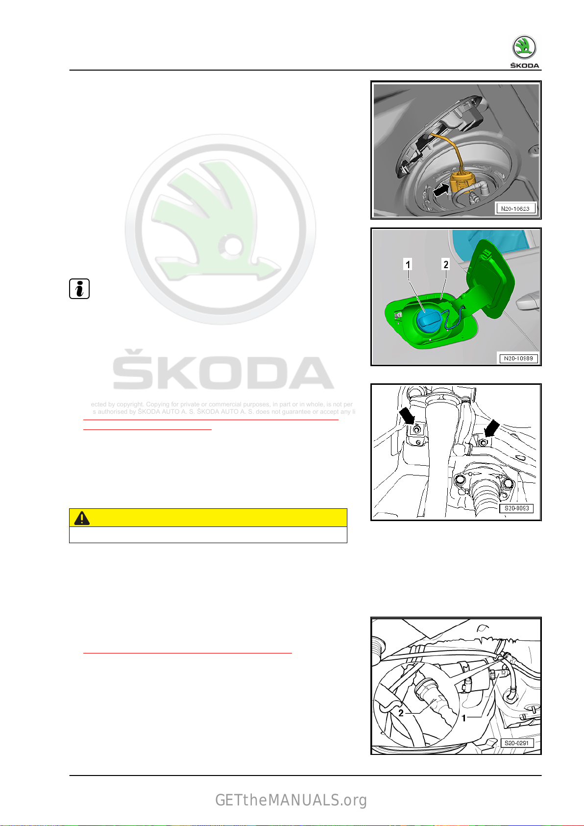
For vehicles with fuel filter outside the fuel tank
– Disconnect the feed line -1- and the vent line -2-
⇒ “3.1 Separating push-on couplings”, page 117 .
1. Fuel tank 25
Protected by copyright. Copying for private or commercial purposes, in part or in whole, is not permitted
unless authorised by ŠKODA AUTO A. S. ŠKODA AUTO A. S. does not guarantee or accept any liability
with respect to the correctness of information in this document. Copyright by ŠKODA AUTO A. S.
Karoq 2018 ➤ , Kodiaq 2017 ➤ , Kodiaq 2019 ➤ , Octavia III 2013 ➤ , Oc ...
GETtheMANUALS.org
Fuel system - Petrol engines - Edition 12.2018
For vehicles with fuel filter in the flange of the fuel delivery unit
– Disconnect
of the fuel tank.
Continued for all vehicles
– Support the fuel tank using the engine and gearbox jack -
V.A.G 1383A- .
– Remove left underfloor trim panel ⇒ General body repairs,
exterior; Rep. gr. 66 ; Underfloor trim panel; removing and
installing underfloor trim panels .
CAUTION
Risk of accident due to the fuel tank weight.
♦ The aid of a 2nd mechanic is required to remove the fuel tank
-1-.
– Unscrew tensioning straps and fixing screw of the fuel tank
-arrows-.
– Carefully lower the engine/gearbox jack -V.A.G 1383A- and
remove
ic.
Fitting
– Check both earth connections for corrosion, if necessary re‐
move corrosion.
the feed line -1-and the vent line on the front right
the fuel tank with the assistance of a second mechan‐
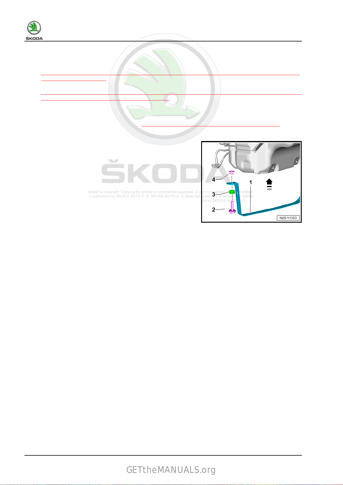
– Check fitting position of the earth lead -1-.
• The plug -1- on the metal plate ring -2- must be pushed on
firmly.
• The contact tab -4- must be hung on the fuel tank -3- and se‐
cured with the spacer bush -5-.
26 Rep. gr.20 - Fuel supply system
 Loading...