

Page 1
SIMPLY CLEVER
ŠKODA Octavia
Owner's Manual
Page 2

Layout of this Owner's Manual
(explanations)
This Owner's Manual has been systematically designed to make it easy for you to
search for and obtain the information you require.
Chapters, table of contents and subject index
The text of the Owner's manual is divided into relatively short sections which are
combined into easy-to-read chapters. The chapter you are reading at any particular
moment is always specified on the bottom right of the page.
The Table of contents is arranged according to the chapters and the detailed Sub-
ject index at the end of the Owner's Manual helps you to rapidly find the information you are looking for.
Direction indications
All direction indications such as “left”, “right”, “front”, “rear” relate to the direction of
travel of the vehicle.
Units of measurement
All values are expressed in metric units.
Explanation of symbols
Denotes a reference to a section with important information and safety
advice in a chapter.
Denotes the end of a section.
Denotes the continuation of a section on the next page.
Indicates situations where the vehicle must be stopped as soon as possi-
ble.
® Denotes a registered trademark.
Denotes the display in the information display.
Denotes the display in the segment display.
Notes
WARNING
The most important notes are marked with the heading WARNING. These
WARNING notes draw your attention to a serious risk of accident or injury.
For the sake of the environment
An Environmental note draws your attention to environmental protection aspects.
This is where you will, for example, find tips aimed at reducing your fuel consumption.
Note
A normal Note draws your attention to important information about the operation
of your vehicle.
CAUTION
Caution note draws your attention to the possibility of damage to your vehicle
A
(e.g. damage to gearbox), or points out general risks of an accident.
Page 3

Preface
You have opted for a ŠKODA – our sincere thanks for your confidence in us.
You have received a vehicle with the latest technology and range of amenities. The new operating concept
allows you to make vehicle settings and to operate electronic systems centrally from the Infotainment system.
In addition to this Owner's Manual, please also carefully read the Infotainment operating manual, because
operation in accordance with these instructions is a prerequisite for proper use of the vehicle.
Observe the national legal requirements when using your vehicle.
If you have any questions about your vehicle, please contact a ŠKODA Partner.
We hope you enjoy driving your ŠKODA, and wish you a pleasant journey at all times.
Your ŠKODA AUTO a.s. (hereinafter referred to only as ŠKODA or manufacturer)
Page 4

On-board literature
The on-board literature for your vehicle consists of this “owner's manual” as well
as a “service schedule” and the “Help on the road” brochure.
Depending on the vehicle model and equipment, other additional operating manuals and instructions may be provided (e.g. an operating manual for the Infotainment Radio).
If one of the documents listed above is missing, please contact a ŠKODA Partner.
Terms used
The on-board literature contains the following terms relating to the service work
for your vehicle.
“Specialist garage” - a company that carries out specialist service tasks for
›
ŠKODA vehicles
“ŠKODA service partner” - a company that is contractually authorized by ŠKODA
›
AUTO a.s. to carry out service tasks for ŠKODA vehicles
“ŠKODA Partners” - a company that is authorized by ŠKODA AUTO a.s. to sell
›
ŠKODA products or carry out service work, or to carry out these tasks in parallel
The owner's manual
This owner's manual describes all possible equipment variants without identifying them as special equipment, model variants or market-dependent equipment.
Consequently, this vehicle does not need to contain all of the equipment compo-
nents described in this owner's manual.
The scope of equipment in your vehicle relates to your sales contract for the vehicle. More information is available from the ŠKODA Partner where you bought the
vehicle.
This owner's manual describes a wide range of electronic functions and systems.
Information about how to configure these electronic functions and systems can
be found in the operating instructions to Infotainment Radio and/or the Infotainment navigation system.
The illustrations can differ in minor details from your vehicle; they are only intended for general information.
The service schedule:
Contains vehicle data including information on service work carried out;
›
Is intended as proof of services carried out;
›
Is intended for records relating to the mobility warranty (only valid for some
›
countries);
Serves as a warranty certificate from the ŠKODA Partner where your vehicle
›
was purchased.
Therefore please always present the service schedule when you take your vehicle
to a specialist garage.
If the service schedule is missing or in poor condition, please contact the specialist garage that regularly services your vehicle. You will need to request a duplicate, in which the specialist garage will confirm the service work previously carried out.
The Help on the Road brochure
The brochure contains the important emergency telephone numbers as well as
telephone numbers and contact addresses of ŠKODA Partners in different countries.
Page 5

Table of Contents
Abbreviations
Using the system
Cockpit 7
Overview 6
Instruments and warning lights 9
Instrument cluster 9
Warning lights 14
Warning icons in the display
Information system 25
Driver information system
Driving data (Multifunction display)
Unlocking and opening 32
Unlocking and locking
KESSY 38
Anti-theft alarm system
Luggage compartment lid
Electric luggage compartment lid (Octavia
Estate)
Electrical power windows 44
Panoramic sliding/tilting roof (Octavia)
Panoramic sliding/tilting roof (Octavia Estate)
Lights and visibility 51
Lights
Interior lights 58
Visibility
Windscreen wipers and washers
Rear mirror 64
Seats and useful equipment
Adjusting the seats 67
Seat features
20
25
28
32
39
40
47
48
60
62
67
Useful equipment 74
Luggage compartment 85
Variable loading floor in the luggage
compartment (Estate) 94
Net partition (Octavia Estate) 96
Roof rack system 98
Heating and air conditioning system 101
Heating, ventilation, cooling 101
Heating 103
Air conditioning system (manual air conditioning
system)
Climatronic (automatic air conditioning
system) 107
Auxiliary heating (auxiliary heating and
ventilation)
Driving
Starting-off and Driving 113
Steering
Start and stop the engine with the key 114
Start and stop the engine - KESSY
Braking
Manual shifting of gears and pedals 121
Automatic transmission
41
Running in 125
Economical driving and environmental
sustainability
Avoiding damage to your vehicle 130
Driving abroad
51
Assist systems 132
Brake assist systems
Parking aid
Park assist 137
Cruise Control System
Adaptive Cruise Control (ACC) 143
Area monitoring system (Front Assist)
71
START-STOP
Driving mode 156
ProActive passenger protection 158
Lane Assist 158
Traffic sign recognition 161
Fatigue detection (break recommendation) 162
Towing a trailer 164
Towing device 164
Trailer 167
Safety
105
Passive Safety 171
General information 171
Correct seated position 172
110
Seat belts
Using seat belts 175
Inertia reel and belt pretensioners
Airbag system
113
Description of the airbag system 180
Airbag overview
116
Deactivating airbags 185
119
Transporting children safely
Child seat
121
Fastening elements 191
General Maintenance
126
Taking care of and cleaning the vehicle
131
Washing your car 193
Taking care of your vehicle exterior
132
Taking care of the interior
135
Modifications, repairs and technical alterations 200
Inspecting and replenishing
141
Fuel 204
Engine compartment
149
Engine oil
153
175
178
180
181
188
188
193
194
198
204
206
210
Table of Contents
3
Page 6

Coolant 212
Brake fluid 214
Vehicle battery 215
Wheels 220
Tyres and wheel rims 220
Winter operation 226
Do-it-yourself
Emergency equipment, and self-help
Emergency equipment 227
Changing a wheel 229
Tyre repair 232
Jump-starting 235
Towing the vehicle
Remote control 238
Emergency unlocking/locking
Replacing windscreen wiper blades
Fuses and light bulbs 243
Fuses
Bulbs 247
227
236
239
241
243
Technical data
Technical data
Vehicle data
254
254
Index
4
Table of Contents
Page 7

Abbreviations
Abbreviation Definition
rpm Engine revolutions per minute
ABS Anti-lock brake system
ACC Adaptive cruise control
AHL Adaptive headlights
TCS Traction control
CO2 in g/km discharged quantity of carbon dioxide in grams per driven kilo-
metre
DPF Diesel particle filter
DSG Automatic double clutch gearbox
DSR Active driver-steering recommendation
EDL Electronic differential lock
EPC EPC fault light
ESC Electronic Stability Control
HBA Hydraulic brake assist
HHC Uphill start assist
kW Kilowatt, measuring unit for the engine output
MG Manual gearbox
N1 Panel van intended exclusively or mainly for the transporta-
tion of goods
Nm Newton meter, measuring unit for the engine torque
TDI CR Diesel engine with turbocharging and common rail injection
system
TSA Trailer stabilisation
TSI Petrol engine with turbocharging and direct injection
Abbreviations
5
Page 8
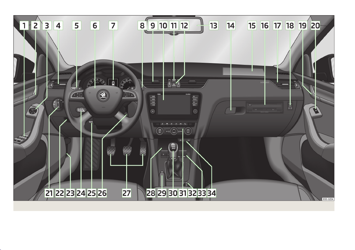
Fig. 1
6
Using the system
Cockpit
Page 9
Using the system
Cockpit
Overview
1
Electrical power windows 44
2
Door opening lever on the driver's side 37
3
Electric exterior mirror adjustment 66
4
Air outlet vent on the driver's side 102
5
Operating lever:
Turn signal light, headlight and parking light, headlight flasher 53
›
Speed regulating system 141
›
Activating the menu item wizard
›
6
Steering wheel:
With horn
›
With driver’s front airbag
›
With keys for the Infotainment control » Infotainment manual,
›
chapter Device Operation
7
Instrument cluster 9
8
Operating lever:
Windscreen wiper and wash system
›
Multifunction display 28
›
Information display
›
9
Air outlets in the central part of the dash panel 102
10
Infotainment » owner's manual for the Infotainment radio or navigation
11
Warning light for the deactivated front seat passenger airbag
12
Button for hazard warning light system
13
Interior rear-view mirror 65
14
Storage compartment on the front passenger side
15
Front passenger airbag 182
16
CD/DVD drive and memory card slot (in the passenger-side storage
compartment) » owner's manual for the Infotainment radio and/or
navigation
17
Air outlet vent on the front passenger side
182
186
102
18
Key switch for switching off the front passenger airbag (in front
passenger storage compartment) 186
19
Door opening lever on the front passenger side 37
20
Power window in the front passenger door 46
21
Light switch 52
22
Storage compartment on the driver's side 75
Fuse box (behind the storage compartment on the driver's side) 244
23
Bonnet release lever 208
24
Operating lever for adaptive cruise control 146
25
Lever for adjusting the steering wheel 114
26
Ignition lock 115
27
Pedals 121
28
Storage compartment/ phone box » Infotainment manual, chapter Phonebox
29
27
62
27
57
81
Handbrake lever
30
Depending on equipment fitted:
Gearshift lever (manual gearbox)
›
Selector lever (automatic gearbox) 122
›
31
Depending on equipment fitted:
Operating controls for the heating
›
Operating controls for the air conditioning system 105
›
Operating controls for Climatronic
›
32
Depending on equipment fitted:
12-Volt power socket 79
›
Cigarette lighter
›
33
Bar with keys depending on the equipment fitted:
Central locking system
›
START STOP 153
›
Traction control TCS
›
Electronic Stability Control ESC
›
Selection of driving mode
›
Park Assist
›
Parking aid
›
Tyre inflation pressure calibration
›
34
Depending on equipment fitted:
USB/AUX input » Infotainment Manual, chapter USB/AUX In-
›
puts
MEDIA IN input » Infotainment Manual, chapter MEDIA IN input
›
120
121
103
107
78
36
133
132
156
137
135
223
Cockpit
7
Page 10

Note
The arrangement of the controls and switches and the location of some items on
right-hand drive models may differ from that shown in » Fig. 1. The symbols on
the controls and switches are the same as for left-hand drive models.
8
Using the system
Page 11
Instruments and warning lights
Instrument cluster
Introduction
This chapter contains information on the following subjects:
Overview
Revolutions counter 10
Display 10
Speedometer 10
Coolant temperature gauge 11
Fuel gauge 11
Counter for distance driven
Setting the time 12
Viewing the charge level vehicle battery
Service interval display
Auto-check control 13
Component protection
If the message SAFE CP appears in the instrument cluster display, the component
protection for the instrument cluster is active. Further information » page 202,
Component protection.
Fault display
If there is a fault in the instrument cluster, the following message will appear in
the display.
Error: Instrument cluster. Workshop!
COMBIINSTRUM_WORKSHOP
Seek help from a specialist garage.
WARNING
■
Concentrate fully at all times on your driving! As the driver you are fully re-
sponsible for the operation of your vehicle.
■
Never operate the button 6 in the instrument cluster » Fig. 2 on page 9
while driving, only when the vehicle is stationary!
Overview
9
12
12
12
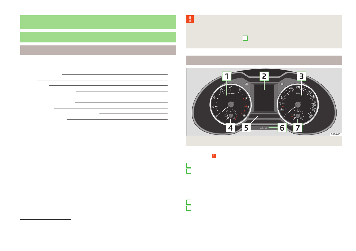
Fig. 2
Instrument cluster
First read and observe the introductory information and safety warnings on page 9.
1
Revolutions counter with warning lights » page 10
2
Display » page 10
With counter for distance driven » page 12
›
With service interval display » page 12
›
With digital clock » page 12
›
With information system » page 25
›
With control symbols » page 20
›
3
Speedometer1) with warning lights » page 10
4
Coolant temperature gauge » page 11
1)
During the journey, the speed can be displayed in a different unit (mph or km/h) in addition to the
tachometer display.
Instruments and warning lights
9
Page 12
5
Bar with warning lights » page 14
6
Button for:
Set hours/minutes » page 12
›
Displaying the distance and days until the next service interval » page 12
›
Resetting Service Interval Display » page 12
›
Reset trip counter for the distance driven » page 12
›
Charge level indicator » page 12
›
7
Fuel gauge » page 11
Revolutions counter
First read and observe the introductory information and safety warnings on page 9.
The red scale of the rev counter 1 » Fig. 2 on page 9 indicates the range in which
the system begins to limit the engine speed. The system automatically restricts
the engine speed to a steady limit.
You should shift into the next higher gear before the red scale of the revolution
counter is reached, or select mode D on the automatic gearbox.
Follow the recommended gear to prevent engine speeds that are too high or too
low » page 26.
For the sake of the environment
Correct shifting up has the following advantages.
■
It helps to reduce fuel consumption.
■
It reduces the operating noise.
■
It protects the environment.
■
It benefits the durability and reliability of the engine.
Display
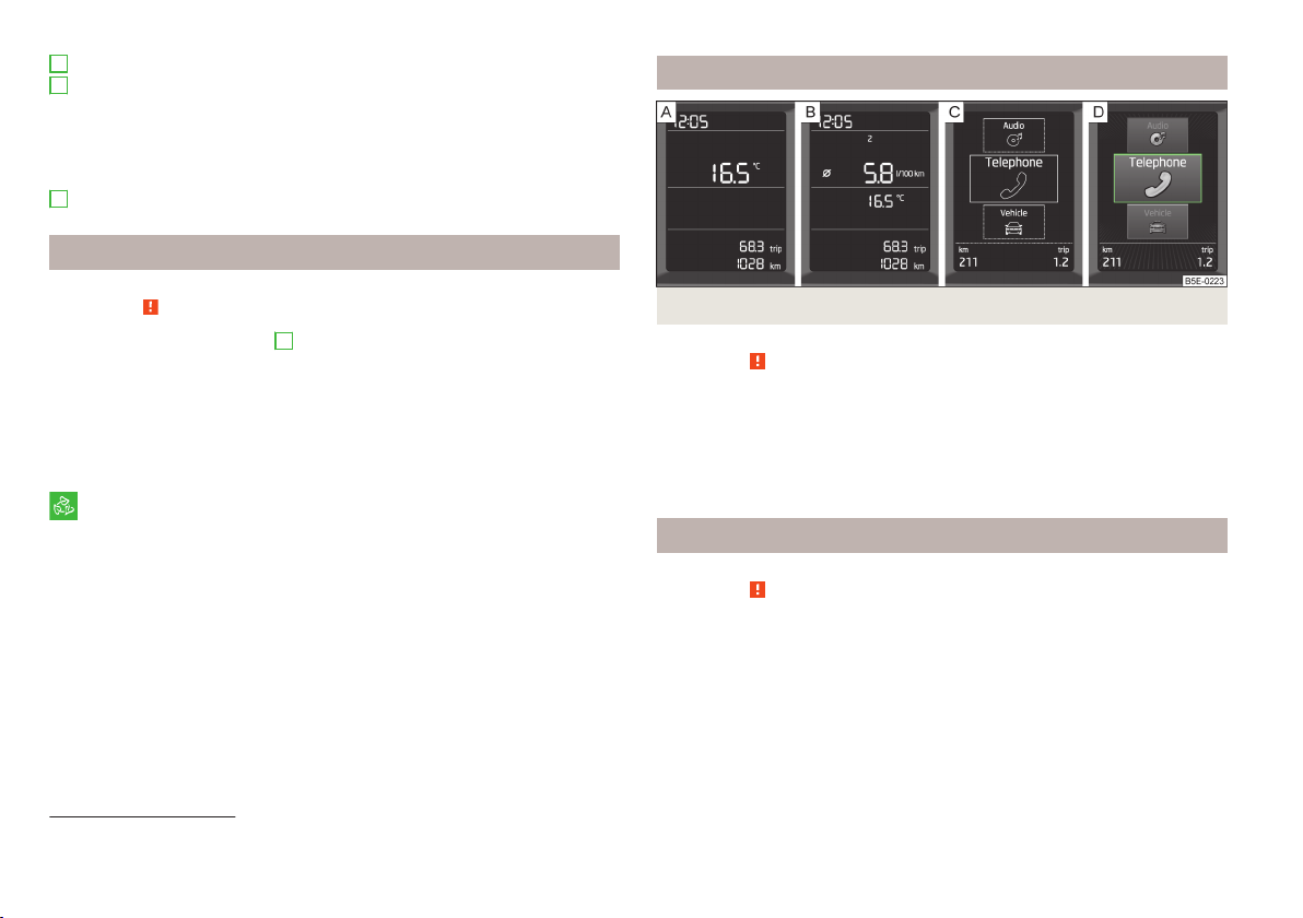
Fig. 3 Display types
First read and observe the introductory information and safety warnings
The instrument cluster can have one of the following types of display » Fig. 3.
Segment display without multi function display
Segment display with multi-function display
Monochromatic information display
Colour information display
on page 9.
Speedometer
First read and observe the introductory information and safety warnings
Warning against excessive speeds
An audible warning signal will sound when the vehicle speed exceeds 120 km/h1).
The audible warning signal is switched off when the vehicle speed falls below
120 km/h.
on page 9.
1)
This function only applies to certain countries.
10
Using the system
Page 13
Coolant temperature gauge
Fuel gauge
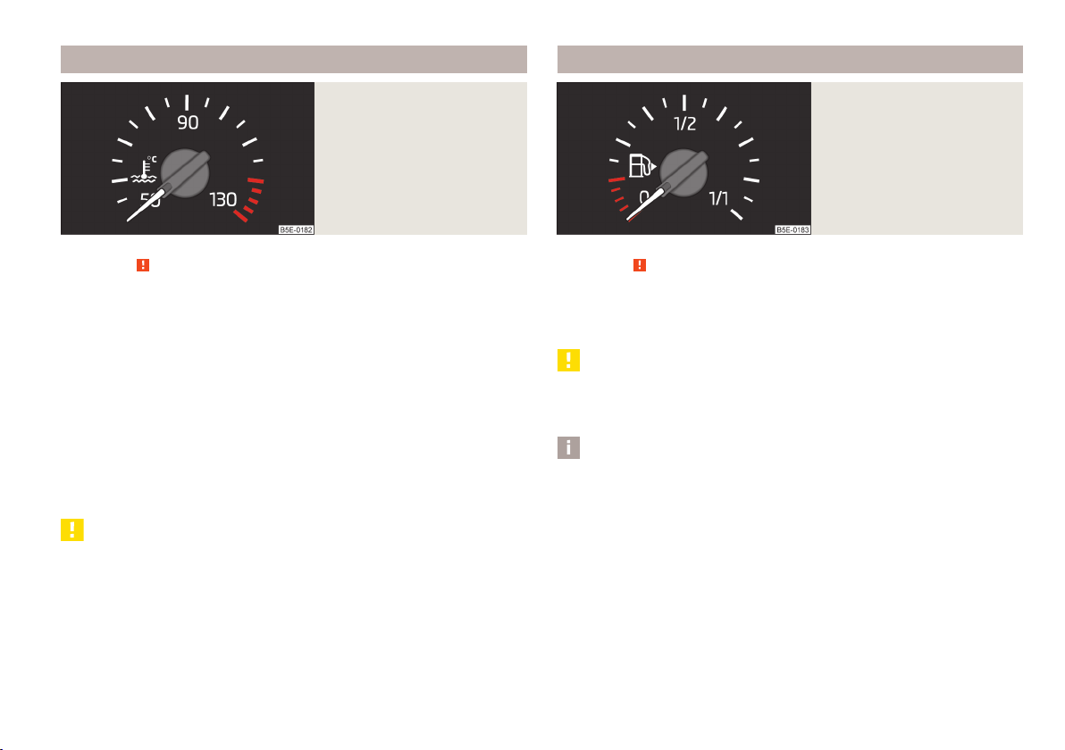
Fig. 4
Coolant temperature gauge
First read and observe the introductory information and safety warnings on page 9.
The coolant temperate display » Fig. 4 only operates when the ignition is switched on.
Cold range
If the pointer is still in the left area of the scale it means that the engine has not
yet reached its operating temperature. Avoid high speeds, full throttle and high
engine loads. This prevents possible damage to the engine.
The operating range
The engine has reached its operating temperature as soon as the pointer moves
into the mid-range of the scale. At very high ambient temperatures or heavy engine loads, the pointer may move even further to the right.
High temperature range
If the pointer reaches the red area of the scale, the coolant temperature is too
high. Further information » page 21.
CAUTION
Additional headlights and other attached components in front of the air inlet impair the cooling efficiency of the coolant.
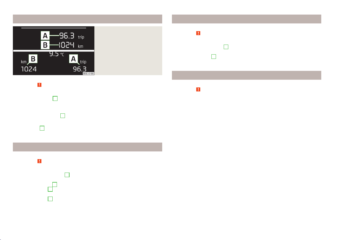
Fig. 5
Fuel gauge
First read and observe the introductory information and safety warnings on page 9.
The fuel gauge » Fig. 5 only operates if the ignition is switched on.
The fuel tank has a capacity of about 50 litres. If the pointer reaches the reserve
marking (red area of the scale), the control indicator » page 23 lights up.
CAUTION
Never drive until the fuel tank is completely empty! The irregular supply of fuel
can cause misfiring, which can result in considerable damage to parts of the engine and exhaust system.
Note
The arrow next to the icon within the fuel gauge displays the installation location of the fuel filler on the right side of the vehicle.
Instruments and warning lights
11
Page 14
Counter for distance driven
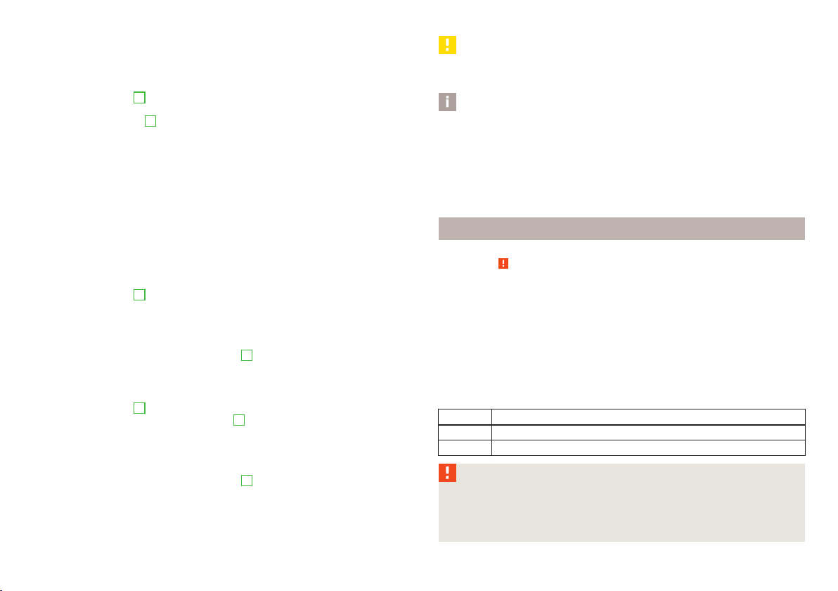
Fig. 6
Segment display/information
display
Viewing the charge level vehicle battery
First read and observe the introductory information and safety warnings on page 9.
Switch off the ignition.
›
Press and hold the button 6 » Fig. 2 on page 9 until the Battery status or BAT-
›
TERY SOC is shown in the display.
Release the button
›
played in %.
6
- the current charge level of the vehicle battery is dis-
First read and observe the introductory information and safety warnings on page 9.
Daily trip counter (trip)
The daily trip counter A » Fig. 6 shows the distance driven since the time the
counter was last reset - in steps of 100 m.
Reset trip counter for the distance driven
Briefly press the button 6 » Fig. 2 on page 9.
›
Odometer
The odometer
driven.
B
» Fig. 6 indicates the total distance which the vehicle has been
Setting the time
First read and observe the introductory information and safety warnings on page 9.
Switch on the ignition.
›
Press and hold the button 6 » Fig. 2 on page 9 until the Time is shown in the
›
display.
Release the button 6, and the system switches to the time setting function.
›
Press the button 6 again and set the hours.
›
Wait around 4 seconds - the system switches to the minutes setting.
›
Press the button 6 again and set the minutes.
›
The time can also be set in the Infotainment » operating instructions for Infotainment, chapter Unit setup.
12
Using the system
Service interval display
First read and observe the introductory information and safety warnings on page 9.
Messages before reaching the scheduled service date
Before reaching the service date, the icon appears in the display after the ignition is switched on, as well as the following message for example.
Oil change in ... Days
OIL CHANGE IN ... DAYS
or
Inspection in ... Days
INSPECT_ IN ... DAYS
The kilometre indicator or the days indicator reduces in steps of 100 km or, where
applicable, days until the service due date is reached.
Messages upon reaching scheduled service date
Once the service interval is reached, the icon appears in the display after the
ignition is switched on, as well as the following message for example.
Oil change now!
OIL CHANGE NOW
or
Inspection now!
INSPEC TION NOW
or
Page 15
Oil change and inspection now!
OIL CHAN_ AND INSPECTION NOW
Displaying the distance and days until the next service interval
Switch on the ignition.
›
Press the button 6 » Fig. 2 on page 9 and keep it pressed down until Service
›
appears.
Release the button 6.
›
The icon appears in the display, as well as the following message for example.
Service in ... km or... days.
SERVICE IN ... km OR... DAYS
Resetting Service Interval Display
If the variable service interval is set in your vehicle and if the service interval display is reset, the variable service interval is switched to the fixed service interval.
We therefore recommend that the Service Interval Display be reset only by a specialist garage, which will reset the display with a vehicle diagnostic tester.
Reset - oil change service
Switch off the ignition (for vehicles with the KESSY system all doors as well as
›
the luggage compartment and bonnet flaps must also be shut).
Press the button
›
Switch on the ignition, the following message displays.
›
Reset oil change service?
RESET OIL SERVICE
Release and then press again the button 6.
›
Reset - Inspection
Switch off the ignition (for vehicles with the KESSY system all doors as well as
›
the luggage compartment and bonnet flaps must also be shut).
Press the button
›
Switch on the ignition and keep button 6 pressed down until the following
›
message displays.
Reset inspection service – are you sure?
RESET SERVICE
Release and then press again the button
›
6
» Fig. 2 on page 9 and keep it pressed down.
6
» Fig. 2 on page 9 and keep it pressed down.
6
.
CAUTION
We recommend that you do not reset the service interval display yourself. Incorrectly setting the service interval display could cause problems to the vehicle.
Note
■
Information is retained in the Service Interval Display even after the vehicle bat-
tery is disconnected.
■
If the instrument cluster is exchanged after a repair, the correct values must be
entered in the counter for the Service Interval Display. We recommend having this
work undertaken by a ŠKODA service partner.
■
For more information on the service intervals » service schedule, chapter service intervals.
Auto-check control
First read and observe the introductory information and safety warnings on page 9.
Certain functions and conditions of individual vehicle systems are checked continuously when the ignition is switched on.
Error messages and/or other information are displayed in the instrument cluster
display.
Some messages are displayed simultaneously with the warning lights » page 14
or warning icons in the display » page 20.
While the operational faults remain unrectified, the messages are always indicated again. After they are displayed for the first time, the symbols or continue
to be indicated without any extra messages for the driver.
Symbol Description
Warning
Danger
WARNING
If you have to stop for technical reasons, then park the vehicle at a safe dis-
tance from the traffic, switch off the engine and activate the hazard warning
light system » page 57. The warning triangle must be set up at the prescri-
bed distance - observe the national legal provisions when doing so.
Instruments and warning lights
13
Page 16
Warning lights
Introduction
This chapter contains information on the following subjects:
Automatic gearbox 14
Handbrake 15
Braking system
Seat belt warning light, front
Power steering
Traction Control System (ASR) 16
Traction control system (TCS) off 17
Electronic Stability Control (ESC) 17
Antilock brake system (ABS)
Rear fog light 17
Exhaust inspection system 17
Glow plug system (diesel engine) 18
Engine performance check (petrol engine)
Safety Systems
Tyre inflation pressure 18
Brake pad thickness 19
Lane following system (Lane Assist) 19
Turn signal system
Trailer turn signal lights
Fog lights 19
Cruise control system 19
Selector lever lock
Main beam 20
Automatic gearbox
First read and observe the introductory information and safety warnings on page 14.
The warning lights indicate a fault or the state of the automatic gearbox.
20
The warning lights indicate certain functions or faults.
Some warning lights can be accompanied by acoustic signals and messages in the
display of the instrument cluster.
After switching on the ignition, some warning lights illuminate briefly as a func-
tion test.
If the tested systems are OK, the corresponding warning lights go out a few sec-
onds after switching on the ignition.
15
The condition of some features and systems is shown by the warning icons on
the display » page 20.
16
16
The warning lights are at the following locations in the instrument cluster » Fig. 2
on page 9.
Revolutions counter
›
Speedometer
›
Bar with warning lights
›
17
1
3
5
WARNING
■
18
18
19
19
Ignoring illuminated warning lights and related messages or instructions in
the display of the instrument cluster may lead to serious personal injury or
damage to the vehicle.
■
If you have to stop for technical reasons, then park the vehicle at a safe dis-
tance from the traffic, switch off the engine and activate the hazard warning
light system » page 57. The warning triangle must be set up at the prescribed distance - observe the national legal provisions when doing so.
■
The engine compartment of your car is a hazardous area. While working in
the engine compartment, be sure to observe the following warnings » page 206, Engine compartment.
14
Using the system
Page 17
Warning light Message Meaning and Action
Error: Gearbox. No reverse gear possible.
GEARBOX ERROR REV_GEAR NOT AVAIL
Error: Gearbox
GEARBOX ERROR
Gearbox overheated.
GEARBOX OVERHEATED
Gearbox overheated. Stop! Log book!
STOP VEHICLE GEARBOX OVERHEAT
Gearbox faulty. Workshop!
GEARBOX FAULTY WORKSHOP
Fault with automatic gearbox, reverse gear cannot be engaged.
Consult a specialist garage for help.
Fault with automatic gearbox.
Consult a specialist garage for help.
The temperature of the automatic gearbox clutches is too high.
Do not drive on!
Stop the vehicle, switch off the engine and wait until the warning light goes off - risk of
gearbox damage! Once the light goes off, you may continue your journey.
If the warning light does not go off, do not continue driving. Seek help from a specialist garage.
The temperature of the automatic gearbox clutches is too high.
Do not drive on!
Stop the vehicle, switch off the engine and wait until the warning light goes off - risk of
gearbox damage!
If the warning light does not go off, do not continue driving. Seek help from a specialist garage.
Fault with automatic gearbox.
Consult a specialist garage for help.
Handbrake
First read and observe the introductory information and safety warnings on page 14.
The warning light comes on if the handbrake is applied.
An acoustic signal will sound if you drive the vehicle above 5 km/h while the
handbrake is still on.
The following message is shown in the information cluster display.
Release the handbrake!
RELEASE HANDBRAKE
Braking system
First read and observe the introductory information and safety warnings on page 14.
If the warning light lights up, the brake fluid level in the brake system is too
low.
The following message is shown in the information cluster display.
Brake fluid: Log book!
BRAKE FLUID PLEASE CHECK
Stop the vehicle, switch off the engine, and check the level of the brake fluid » page 214 »
If the warning light lights up together with the warning light , there is a
problem with the ABS.
.
Instruments and warning lights
15
Page 18

WARNING
■
If the warning light is displayed simultaneously with warning light
» page 17, Antilock brake system (ABS), do not continue your jour-
ney! Seek help from a specialist garage.
■
A fault to the braking system can increase the vehicle's braking distance -
risk of accident!
Seat belt warning light, front
First read and observe the introductory information and safety warnings on page 14.
The warning light comes on after the ignition is switched on as a reminder for
the driver and front passenger to fasten the seat belt.
The warning light goes out if the driver or front passenger has fastened their
seat belt.
If the driver or front passenger has not fastened their seat belt and the vehicle
speed is more than 30 km/h, the warning light flashes and you will hear an
acoustic signal.
If the seat belt is not fastened by the driver or front passenger during the next
approx. 2 seconds, the warning signal is deactivated and the warning light
lights up permanently.
Further information » page 175, Seat belts.
Power steering
First read and observe the introductory information and safety warnings on page 14.
If the warning light lights up, this indicates a partial failure of the power steering and the steering forces can be greater. Seek help from a specialist garage.
If the warning light lights up, this indicates a complete failure of the power
steering and the steering assist has failed (significantly higher steering forces).
Seek help from a specialist garage.
Further information » page 114.
Note
If the vehicle's battery has been disconnected and reconnected, the warning light
comes on after switching on the ignition. The warning light should go out after
driving a short distance. If after a new engine start and a short ride the yellow
warning light does not go out, seek help from a specialist garage.
Traction Control System (ASR)
First read and observe the introductory information and safety warnings on page 14.
If your vehicle is equipped with the ESC system, the TCS is part of the
ESC » page 132.
The warning light flashes to show that the ASR is currently operating.
If the warning light lights up, there is a fault in the ASR.
The following message is shown in the information cluster display.
Error: Traction control
ASR ERROR
Seek help from a specialist garage.
If the warning light comes on after starting the engine, the TCS may be switch-
ed off for technical reasons. Switch the ignition off and on again. If the warning
light does not light up after you switch the engine back on, the TCS is fully
functional again.
Further information » page 132 and » page 133, Traction Control System (TCS).
Note
If the vehicle's battery has been disconnected and reconnected, the warning light
comes on after switching on the ignition. If the warning light does not go out
after moving a short distance, this means there is an error in the system. Seek
help from a specialist garage.
16
Using the system
Page 19

Traction control system (TCS) off
First read and observe the introductory information and safety warnings on page 14.
If the warning light is lit, the TCS is off.
The following message is shown in the information cluster display.
Traction control (ASR) deactivated.
ASR OFF
Further information » page 133, Traction Control System (TCS).
Electronic Stability Control (ESC)
First read and observe the introductory information and safety warnings on page 14.
A flashing warning light shows that the ESC system is currently operating.
If the warning light lights up, there is a fault in the ESC system.
The following message is shown in the information cluster display.
Error: Electronic Stability Control (ESC)
ESC ERROR
Seek help from a specialist garage.
If the warning light comes on after starting the engine, the ESC system may be
switched off for technical reasons.
Switch the ignition off and on again.
›
If the warning light does not light up after you switch the engine back on, the
ESC system is fully functional again.
Further information » page 132, Electronic Stability Control (ESC).
Note
If the vehicle's battery has been disconnected and reconnected, the warning light
comes on after switching on the ignition. If the warning light does not go out
after moving a short distance, this means there is an error in the system. Seek
help from a specialist garage.
Antilock brake system (ABS)
First read and observe the introductory information and safety warnings on page 14.
If the warning light lights up, there is a fault in the ABS.
The following message is shown in the information cluster display.
Error: ABS
ABS ERROR
The vehicle will only be braked by the normal brake system without the ABS.
Seek help from a specialist garage.
Further information » page 133, Antilock Braking System (ABS).
WARNING
■
If the warning light is displayed simultaneously with warning light ,
do not continue your journey! Seek help from a specialist garage.
■
A fault to the ABS system or the braking system can increase the vehicle's
braking distance – risk of accident!
Rear fog light
First read and observe the introductory information and safety warn-
on page 14.
ings
The warning light comes on when the rear fog light is switched on.
Further information » page 56.
Exhaust inspection system
First read and observe the introductory information and safety warnings on page 14.
If the warning light lights up, there is a fault in the exhaust inspection system.
The system allows the vehicle to run in emergency mode.
Seek help from a specialist garage.
Instruments and warning lights
17
Page 20

Glow plug system (diesel engine)
First read and observe the introductory information and safety warnings on page 14.
The warning light comes on after the ignition has been switched on. Once the
light has gone out, the engine can be started immediately.
There is a fault in the glow plug system if the warning light does not come on
at all or lights up continuously.
If the warning light begins to flash while driving, a fault exists in the engine
control. The system allows the vehicle to run in emergency mode.
Seek help from a specialist garage.
Engine performance check (petrol engine)
First read and observe the introductory information and safety warnings on page 14.
If the warning light
allows the vehicle to run in emergency mode.
Seek help from a specialist garage.
Safety Systems
First read and observe the introductory information and safety warnings
Fault with airbag system
When the warning light lights up and the following message appears in the instrument cluster display, there is a fault with the airbag system.
Error: Airbag
AIRBAG ERROR
The functionality of the airbag system is monitored automatically even if one of
the airbags is switched off.
lights up, there is a fault in the engine control. The system
on page 14.
One of the airbags or a belt tensioner has been disabled by the diagnostic tool
The warning light lights up for approx. 4 seconds after switching on the igni-
›
tion and then flashes again for approx. 12 seconds.
The following message is shown in the information cluster display.
›
Airbag/belt tensioner deactivated.
AIRBAG/BELT TENSIONER OFF
The front passenger airbag has been disabled with the key switch
The warning light comes on for about 4 seconds after the ignition has been
›
switched on.
The warning light in the display in the middle of the dash
›
panel lights up after switching on the ignition » page 186.
ProActive passenger protection
When the warning light lights up and the following message appears in the instrument cluster display, there is a fault with the airbag system. Seek help from a
specialist garage.
ProActive passenger protection not available.
PROACTIVE PASSENGER PROTECT NOT AVAIL
or
ProActive passenger protection: funct. restricted.
LIMITED PROACTIVE PASSENGER PROTECT
WARNING
If there is a fault in the safety system, have it checked immediately by a specialist garage. Otherwise, there is a risk of the systems not being activated in
the event of an accident.
Tyre inflation pressure
First read and observe the introductory information and safety warnings on page 14.
The warning light lights up, if there is a substantial drop in inflation pressure in
one of the tyres. Check and adjust the pressure in all tyres » page 220.
An audible signal sounds as a warning signal.
If the warning light flashes, there is a fault in the system.
18
Using the system
Page 21

Seek help from a specialist garage.
Further information » page 223, Tyre control display.
Note
If the vehicle's battery has been disconnected and reconnected, the warning light
comes on after switching on the ignition. If the warning light does not go out
after moving a short distance, this means there is an error in the system. Seek
help from a specialist garage.
Brake pad thickness
First read and observe the introductory information and safety warnings on page 14.
If the indicator light is lit, the brake pads are worn.
The following message is shown in the information cluster display.
Check brake wear!
BRAKE PADS PLEASE CHECK
Seek help from a specialist garage.
Lane following system (Lane Assist)
First read and observe the introductory information and safety warn-
on page 14.
ings
The warning lights indicates the state of the Lane Assist system.
Further information » page 158.
Turn signal system
First read and observe the introductory information and safety warnings on page 14.
Either the left or right indicator light flashes depending on the position of
the control lever.
If there is a fault in the turn signal system, the warning light flashes at twice its
normal rate. This does not apply when towing a trailer.
Switching off the hazard warning light system is switched on will cause all of the
turn signal lights as well as both warning lights to flash.
Further information » page 53, Turn signal and main beam.
Trailer turn signal lights
First read and observe the introductory information and safety warnings on page 14.
if the warning light flashes, the trailer turn signal lights are turned on.
If a trailer is hitched and the warning light is not flashing, one of the trailer turn
signal lights has failed.
The following message is shown in the information cluster display, for example.
Trailer: check left turn signal!
TRAILER TURN SIG_ CHECK LEFT
The trailer must be unhitched properly » page 164, Towing a trailer.
Fog lights
First read and observe the introductory information and safety warnings on page 14.
The warning light comes on when the fog lights are operating.
Further information » page 56.
Cruise control system
First read and observe the introductory information and safety warn-
on page 14.
ings
The warning light comes on when the cruise control is active.
Further information » page 141.
Instruments and warning lights
19
Page 22
Selector lever lock
First read and observe the introductory information and safety warnings on page 14.
If the warning light lights up, operate the brake pedal.
Further information » page 122.
Main beam
First read and observe the introductory information and safety warnings
The warning light comes on when the main beam is selected or when the
headlight flasher is operated.
Further information » page 53.
on page 14.
Warning icons in the display
Introduction
This chapter contains information on the following subjects:
Rear seat belt warning 21
Alternator 21
Coolant
Engine oil pressure
Engine oil level
Bulb failure
Diesel particle filter (diesel engine)
Windscreen washer fluid level
Fuel reserve
Headlight assist
START-STOP-system
Ice warning
The warning icons indicate the status of certain functions or faults.
The warning icons are indicated in the display of the instrument cluster » page 10.
After switching on the ignition, some warning icons illuminate briefly as a function test.
If the tested systems are OK, the corresponding warning icons go out a few seconds after switching on the ignition.
Depending on the meaning of the warning icon, the icon or will also light up
in the bar with the warning lights 5 » Fig. 2 on page 9.
Some warning icons can be accompanied by acoustic signals and messages in the
instrument cluster display.
The status of some features and systems is shown by the warning
lights » page 14.
Symbol Description
While the operational faults remain unrectified, the messages are always indica-
ted again. After they are displayed for the first time, the symbols or continue
to be indicated without any extra messages for the driver.
On vehicles with a colour information display » Fig. 3 on page 10 - , some warning icons in the display are in colour.
Warning
Danger
WARNING
■
Ignoring illuminated warning icons and related messages or instructions in
the display of the instrument cluster may lead to serious personal injury or
damage to the vehicle.
■
21
21
22
22
22
23
23
23
23
24
If you have to stop for technical reasons, then park the vehicle at a safe distance from the traffic, switch off the engine and activate the hazard warning
light system » page 57. The warning triangle must be set up at the prescribed distance - observe the national legal provisions when doing so.
■
The engine compartment of your car is a hazardous area. While working in
the engine compartment, be sure to observe the following warnings » page 206, Engine compartment.
20
Using the system
Page 23

Rear seat belt warning
First read and observe the introductory information and safety warnings on page 20.
A rear seat belt is not fastened
A rear seat belt is fastened
The warning icons or come on after the ignition has been switched on.
When the seat belt is fastened/unfastened, the particular icon lights up briefly
and indicates the current belt status!
Further information » page 175, Seat belts.
Alternator
First read and observe the introductory information and safety warnings
The warning icon lights up if the vehicle battery is not charged when the engine is running.
Seek help from a specialist garage.
on page 20.
CAUTION
If the icon (cooling system fault) comes on in addition to the icon when driving, stop the vehicle immediately and switch off the engine – risk of engine damage!
Coolant
First read and observe the introductory information and safety warnings on page 20.
Coolant level too low
If the coolant level is too low, the warning icon lights up and the following
message appears in the instrument cluster display.
ENGINE COOLANT PLEASE CHECK Log book!
ENGINE COOLANT PLEASE CHECK
Stop the vehicle, switch off the engine, and check the coolant level » page 213.
›
If the coolant level is too low, add coolant to the reservoir » page 214.
›
If, after adding coolant and switching on the ignition, the warning icon disap-
›
pears, you can continue your journey.
If the coolant level is within the specified range, but the warning icon is still
›
lit, check the fuse for the radiator fan and replace it if necessary » page 246,
Fuses in the engine compartment.
If the coolant level and fan fuse are in order, but the warning icon is still lid,
›
do not continue your journey!
Seek help from a specialist garage.
›
Coolant temperature too high
If the coolant temperature is too high, the warning icon lights up and the fol-
lowing message appears in the instrument cluster display.
Engine overheat. Stop! Log book!
ENGINE OVERHEAT STOP
Stop the vehicle and turn off the engine.
›
Wait until the coolant temperature gauge pointer returns to the operating
›
range » page 11.
Continue your journey only after the warning icon has disappeared.
›
WARNING
■
Carefully open the coolant expansion bottle. If the engine is hot, the cooling
system is pressurized – risk of scalding! It is therefore best to allow the engine
to cool down before removing the cap.
■
Do not touch the radiator fan. The radiator fan may switch itself on automatically even if the ignition is off.
Engine oil pressure
First read and observe the introductory information and safety warnings on page 20.
When the warning icon flashes, the engine oil pressure is too low.
The following message is shown in the information cluster display.
Oil pressure: Stop! Log book!
STOP VEHICLE OIL PRESSURE
Instruments and warning lights
21
Page 24

Stop the vehicle, switch off the engine, and check the level of the engine
oil » page 211, Checking the oil level.
Even if the oil level is correct, do not drive any further if the warning icon is
flashing! Also do not leave the engine running at an idling speed.
Seek help from a specialist garage.
Engine oil level
First read and observe the introductory information and safety warnings on page 20.
Engine oil level too low
If the warning icons and are lit, the engine oil level is too low.
The following message is shown in the information cluster display.
Oil level: top up oil!
TOP UP OIL
Stop the vehicle, switch off the engine, and check the level of the engine
oil » page 211.
The warning icon will go out if the bonnet is left open for more than 30 seconds.
If no engine oil has been replenished, the warning icon will come on again after
driving about 100 km.
Engine oil level too high
If the warning icons and are lit in conjunction with the following message on
the display, the engine oil level is too high.
Reduce oil level!
OIL LEVEL TOO HIGH
Stop the vehicle, switch off the engine, and check the level of the engine
oil » page 211.
Engine oil level sensor
If the warning icons and are lit in conjunction with the following message on
the display, the engine oil level sensor is defective.
Oil sensor: Workshop!
OIL SENSOR WORKSHOP
Seek help from a specialist garage.
WARNING
Do not continue your journey if for some reason it is not possible to top up
the engine oil under the prevailing conditions! Switch off the engine and seek
assistance from a specialist garage.
Bulb failure
First read and observe the introductory information and safety warnings on page 20.
The warning icon comes on if a bulb is faulty.
The following message is shown in the information cluster display, for example.
Check right dipped headlight beam!
DIPPED HEADLIGHT CHECK RIGHT
Diesel particle filter (diesel engine)
First read and observe the introductory information and safety warnings
The diesel particulate filter separates the soot particles from the exhaust. The
soot particles collect in the diesel particulate filter where they are burnt on a regular basis.
If the warning icon lights up, soot has accumulated in the diesel particulate
filter.
To clean the diesel particle filter, and where traffic conditions permit »
for at least 15 minutes or until the warning icon goes out as follows.
4. or gear 5 engaged (automatic gearbox: Position D/S).
›
Vehicle speed at least 60 km/h.
›
Engine speed between 1800-2500 rpm.
›
If the filter is properly cleaned, the warning icon goes out.
If the filter is not properly cleaned, the warning icon does not go out and the
warning icon begins to flash.
on page 20.
, drive
22
Using the system
Page 25

The following message is shown in the information cluster display.
Diesel particulate filter: Log book!
DIESEL PM FILTER OWNER MANUAL
Seek help from a specialist garage.
WARNING
■
The diesel particle filter achieves very high temperatures. Therefore do not
park in areas where the hot filter can come into direct contact with dry grass
or other combustible materials – there is the risk of fire!
■
Always adjust your speed to suit weather, road, region and traffic conditions. The recommendations indicated by the warning light must not tempt
you to disregard the national regulations for road traffic.
Top up with liquid » page 209.
Fuel reserve
First read and observe the introductory information and safety warnings on page 20.
If the warning icon comes on, there is a fuel reserve of under about 7 litres left.
The following message is shown in the information cluster display.
Please refuel. Range: ... km
PLEASE REFUEL
An audible signal sounds as a warning signal.
CAUTION
■
As long as the warning icon lights up, you must take into account an in-
creased fuel consumption and in certain circumstances a power reduction of the
engine.
■
Using diesel fuel with an increased sulphur content can considerably reduce the
life of the diesel particle filter. A ŠKODA partner will be able to tell you which
countries use diesel fuel with a high sulphur content.
Note
■
We encourage you to avoid constant short journeys. This will improve the com-
bustion process of the soot particles in the diesel particulate filter.
■
If the engine is turned off during the filter cleaning process or shortly after-
wards, the cooling fan may turn on automatically for a few minutes.
Windscreen washer fluid level
First read and observe the introductory information and safety warnings on page 20.
If the windscreen washer fluid level is too low, the warning icon comes on.
The following message is shown in the information cluster display.
Top up washer fluid!
WASHER FLUID PLEASE TOP UP
Note
The text in the display goes out after refuelling and driving a short distance.
Headlight assist
First read and observe the introductory information and safety warnings
The warning icon is lit when the headlight assist is activated.
Further information » page 55, Headlight assist.
START-STOP-system
The warning icons indicate the state of the START-STOP system.
Further information » page 153.
on page 20.
First read and observe the introductory information and safety warnings on page 20.
Instruments and warning lights
23
Page 26

Ice warning
First read and observe the introductory information and safety warnings on page 20.
The warning icon draws your attention to the risk of ice.
Further information » page 25.
24
Using the system
Page 27
Information system
Driver information system
Introduction
This chapter contains information on the following subjects:
Information on the display
Outside temperature 25
Recommended gear 26
Door, luggage compartment or bonnet warning 26
Eco tips 26
Laptimer (Stopwatch) 26
Information display
WARNING
Concentrate fully at all times on your driving! As the driver you are fully responsible for the operation of your vehicle.
Information on the display
First read and observe the introductory information and safety warnings on page 25.
The information system provides the driver with alerts and messages about individual vehicle systems. These alerts and messages appear in the display of the instrument cluster
The information system provides the following information.
Outside temperature » page 25.
›
Recommended gear » page 26.
›
Door, boot lid and bonnet warning » page 26.
›
Eco tips » page 26.
›
Service interval display » page 12.
›
Auto Check Control » page 13.
›
Warning icons » page 20.
›
Driving data (multifunction display) » page 28.
›
2
» Fig. 2 on page 9 (hereafter only in the display).
Warning against excessive speeds » page 31.
›
Details of the information display » page 27.
›
Traffic sign recognition » page 161.
›
Fatigue detection » page 162.
›
Selector lever positions for an automatic gearbox » page 122.
›
Information and alerts in the Assist systems » page 132.
›
Outside temperature
25
27
First read and observe the introductory information and safety warnings
The current outside temperature is shown in the display.
If the outside temperature drops below +4 °C while driving, the following symbol
(warning signal for ice on the road) appears before the temperature indicator
and an audible signal will sound.
If the outside temperature is less than +4 °C when the ignition is turned on, the
following symbol appears in the display and an acoustic signal sounds.
After pressing the rocker switch A or the adjustment wheel D » Fig. 10 on
page 30, the function shown last is indicated.
on page 25.
WARNING
Even at temperatures around +4 °C, black ice may still be on the road surface!
Do not only rely upon the information given on the outside temperature display that there is no ice on the road.
Information system
25
Page 28
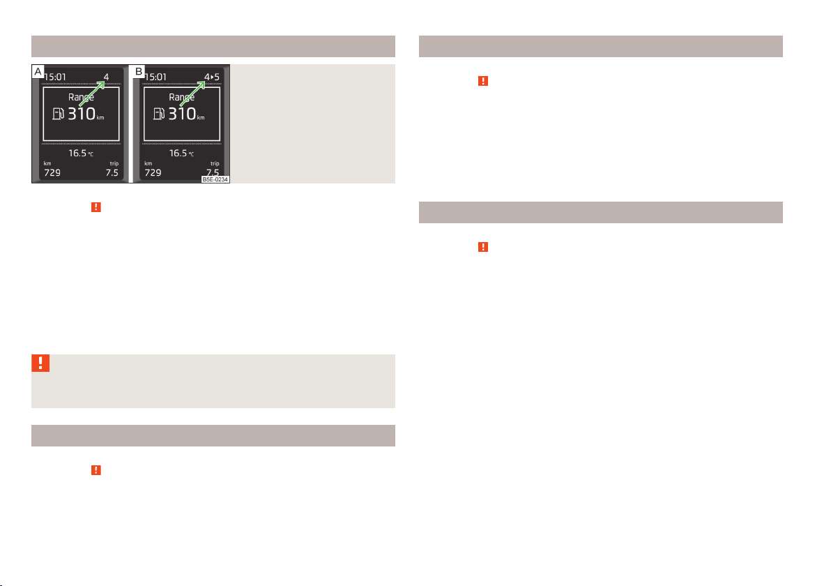
Recommended gear
Fig. 7
Recommended gear
First read and observe the introductory information and safety warnings on page 25.
In order to minimise the fuel consumption, a recommendation for shifting into another gear is indicated in the display.
Information about the currently-selected gear is shown in the upper part of the
display » Fig. 7 - .
When the system determines that a change in gear is required, the arrow symbol
and the recommended gear appear next to the current gear indication » Fig. 7 -
.
For instance, if appears in this display, this means it is recommended that
you shift from 4th into 5th gear.
WARNING
The driver is always responsible for selecting the correct gear in different driving situations, such as overtaking.
Door, luggage compartment or bonnet warning
First read and observe the introductory information and safety warnings on page 25.
If at least one door is open, or the boot or bonnet is open, the display indicates
the relevant open door or boot/bonnet.
An acoustic signal will also sound if you drive the vehicle above 6 km/h.
Eco tips
First read and observe the introductory information and safety warnings on page 25.
To minimise fuel consumption, fuel economy tips can appear in the display.
Eco tips are indicated next to the letters ECO-TIP.
For instance, if the air-condition is on and a window is open, the following mes-
sage appears ECO TIP Air conditioning switched on: close windows.
Eco tips display must be activated in the Infotainment » operating instructions for
Infotainment, chapter Vehicle settings (CAR button).
Laptimer (Stopwatch)
First read and observe the introductory information and safety warnings
The Laptimer function offers the possibility of calculating the lap time, for example when driving on a race course. The calculated time is displayed in the information display.
The Laptimer function is operated with the buttons on the control lever or the
buttons on the steering wheel » page 27, Information display.
The calculated times are displayed in minutes, seconds and deciseconds.
Activate Laptimer function
From the main menu of the information display select the menu item Laptimer .
›
The following functions are available.
■
Start - Start the timing manually or continue the interrupted measurement
■
From Start - Start the timer automatically upon start-up
■
Statistics - Evaluate and reset the measured times
Time measurement
Manually start the measurement
Select the menu item Laptimer - Start.
›
Start the measurement automatically
Select the menu item Laptimer - From Start. Timing will begin automatically
›
when starting up.
on page 25.
26
Using the system
Page 29
Start timing of next round
Select the menu item New round during timing.
›
During timing, information about the fastest and the last lap time are also displayed in the information display .
Measure split time
During the timing, select the menu item split time. The split time data is dis-
›
played for about 5 seconds in the information display.
The split time can be measured repeatedly during a round.
Stop measurement
During the timing, press the menu item Stop.
›
The time measurement is stopped, the following functions are now available.
■
Continue - Continue measurement of the current lap time
■
New round - Start measurement of the next lap time.
■
Abort lap - Cancel the timer (the aborted lap time is not stored)
■
End - End timing (the aborted lap time is stored)
Evaluate recorded times
Select the menu item Lap timer - Statistics.
›
The following information is displayed.
Fastest: - The fastest lap
›
Slowest: - The slowest lap
›
Average: - The average lap time
›
Overall time: - The total of all the lap times
›
Reset measured times
Select the menu item Lap timer - Statistics - Reset.
›
WARNING
Concentrate fully at all times on your driving! As the driver you are fully responsible for the operation of your vehicle. Only use the Laptimer system
when you are in any traffic situation where you have full control over the vehicle.
Note
■
The system allows the measurement of up to 11 lap times.
■
Measurement of each individual lap ends after 99 hrs, 59 min. and 59 sec. Once
this time has been reached, measurement of the new lap starts automatically.
■
The measured times cannot be reset individually.
■
If the measured times are not reset, then these are stored even after turning
off the ignition.
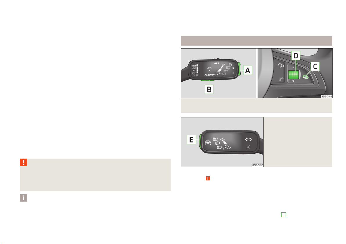
Information display
Fig. 8 Buttons (adjustment wheel) on the operating lever/multifunction
steering wheel
Fig. 9
Operating lever: Button to open
the menu item wizard
First read and observe the introductory information and safety warnings
The information display provides you with information on the current operating
state of your vehicle. The information display also provides you with data (de-
pending on the equipment installed in the vehicle) relating to the Infotainment,
multi-functional indicator, etc.
Operating with the buttons on the operating lever
Activate the Main menu by pressing the rocker switch
on page 25.
A
» Fig. 8 for longer.
Information system
27
Page 30
Individual menu items can be selected by means of the rocker switch A. When
the pushbutton B is briefly pressed, the information you have selected is displayed.
Operating the button/adjustment wheel on the multifunction steering wheel
Activate the Main menu by briefly pressing the rocker switch C » Fig. 8.
The individual menus can be selected by pressing the adjustment wheel D. The
selected menu is displayed after briefly pressing the adjustment wheel D.
By briefly pressing the C button you will reach one level higher.
Main menu points
The following information can be selected (depending on the equipment installed
on the vehicle).
■
Driving data » page 28
■
Wizard » page 158, » page 149
■
Navigation » operating instructions for Infotainment, chapter Navigation system (NAV button)
■
Audio » operating instructions for Infotainment, chapter Media (MEDIA button)
■
Telephone » operating instructions for Infotainment, chapter Communication
(PHONE button)
■
Vehicle » page 13, Auto-check control
■
Lap timer » page 26
Menu item wizard
In the menu item wizard, by pressing the button
D,
» Fig. 8 the systems Front Assist and Lane Assist can be enabled or disabled.
The menu item wizard in the main menu can also be opened by pressing the button E on the control lever » Fig. 9.
B
or the adjustment wheel
Note
If warning messages are shown in the information display, these messages must
be confirmed with the button B on the operating lever » Fig. 8 or with the adjustment wheel D on the multifunction steering wheel to call up the main menu.
Driving data (Multifunction display)
Introduction
This chapter contains information on the following subjects:
Information overview
Select information 30
Memory 30
Warning at excessive speeds 31
The multifunction display only operates if the ignition is switched on.
After the ignition is switched on, the function displayed is the one which you last
selected before switching off the ignition.
Individual menu items can be shown or hidden in the Infotainment » Bedienung-
sanleitung Infotainment, chapter Vehicle settings (CAR button).
WARNING
Concentrate fully at all times on your driving! As the driver you are fully responsible for the operation of your vehicle.
Note
In some national versions the displays appear in the Imperial system of measurement.
Information overview
First read and observe the introductory information and safety warnings on page 28.
Range
The range indicates the distance you can still drive with your vehicle based on the
level of fuel in the tank and the same style of driving as before.
The display is shown in steps of 10 km. After lighting up of the warning icon the
display is shown in steps of 5 km.
The fuel consumption over the last 50 km is used to calculate the range. The
range can increase if you drive in a more fuel-efficient manner.
28
28
Using the system
Page 31

Average fuel consumption
The average fuel consumption1) is calculated since the last time the memory was
erased » page 30.
If you wish to determine the average fuel consumption over a certain period of
time, you must set the memory at the start of the new measurement to
zero » Fig. 10 on page 30.
After erasing the memory, no fuel consumption data will appear for the first
100 m driven.
The fuel consumption data is updated continuously while you are driving.
Current fuel consumption
You can use this information to adapt your driving style to the desired fuel consumption1).
The display appears in litres/hour if the vehicle is stationary or driving at a low
speed2).
Oil temperature
If the engine oil temperature is in the range 80-110 °C, the engine operating temperature is reached.
If the temperature lies below 80 °C or above 110 °C, avoid high engine revs, full
throttle and high engine loads.
If the oil temperature is lower than 50 °C or if a fault in the system for checking
the oil temperature is present,
are displayed instead of the oil temperature.
Warning against excessive speeds
Set the speed limit, for example, for the maximum permissible speed in
town » page 31.
Traffic sign recognition
The display can show up to three of the following traffic signs simultaneously.
Maximum permissible speed (including additional signs).
›
Overtaking prohibited.
›
Further information » page 161, Traffic sign recognition.
Current driving speed
The current speed is identical to the display on the speedometer 3 » Fig. 2 on
page 9.
Average speed
The average speed since the memory was last erased is shown in the display
in km/hour » page 30.
To determine the average speed over a certain period of time, set the memory to
zero at the start of the measurement » page 30.
After erasing the memory, no average speed data will appear for the first 300 m
driven.
The average speed data is updated regularly while you are driving.
Distance travelled
The distance driven since the memory was last erased appears in the display.
If you want to measure the distance travelled from a particular moment in time
on, at this moment, reset the memory by setting the button to zero » page 30.
The maximum distance indicated is 9999 km. The indicator is automatically set
back to zero if this period is exceeded.
Driving time
The driving time which has elapsed since the memory was last erased, appears in
the display.
If you want to measure the time travelled from a particular moment in time on, at
this moment, reset the memory by setting the button to zero » page 30.
The maximum distance indicated is 99 hours and 59 minutes. The indicator is set
back to zero if this period is exceeded.
Convenience consumers
The consumption display for the convenience consumers in l/h.
Together with the consumption display, a list of three convenience consumers
with the highest consumption is also displayed.
1)
The units for the displayed consumption are set in the Infotainment » Bedienungsanleitung Infotainment, chapter Device Settings.
2)
On some models in certain countries, the display appears in --,- kilometres/litres if the vehicle is stationary.
Information system
29
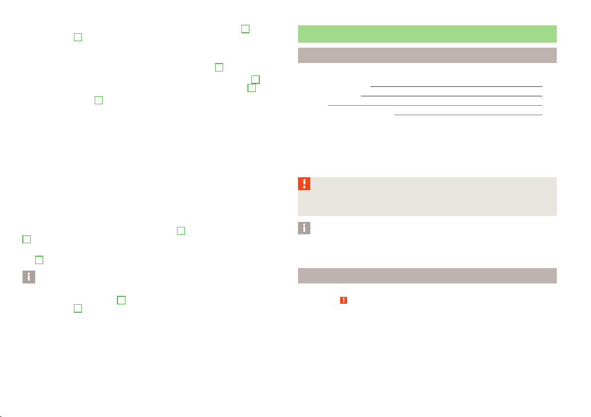
Page 32

Select information
Fig. 10 Buttons (adjustment wheel) on the operating lever/multifunction
steering wheel
First read and observe the introductory information and safety warnings on page 28.
Selecting using the operating lever
Briefly press the rocker switch A » Fig. 10 up or down.
›
Selecting using the multifunction steering wheel
Turn the adjustment wheel D » Fig. 10 upwards or downwards.
›
Memory
First read and observe the introductory information and safety warnings
The multifunction display is equipped with three automatic memories.
Select memory
Press the button B or the adjustment wheel D» Fig. 10 on page 30 briefly.
›
Resetting
Select the desired memory.
›
Press longer on the button B or adjustment wheel D » Fig. 10 on page 30.
›
The following values of the selected memory are set to zero.
Average fuel consumption.
›
Distance driven.
›
on page 28.
Average speed.
›
Driving time
›
Since start
The memory collates the driving information from the moment the ignition is
switched on until it is switched off.
New data will also flow into the calculation of the current driving information if
the trip is continued within 2 hours after switching off the ignition.
If the trip is interrupted for more than 2 hours, the memory is automatically
erased.
Long-term
The memory gathers driving information from any number of individual journeys
up to a total of 99 hours and 59 minutes driving or 9999 kilometres driven.
The memory is deleted when either of these limits is reached and the calculation
starts all over again.
Since refuel
The memory gathers driving information since the last refuelling.
The memory is erased automatically the next time you fill up.
Note
Disconnecting the vehicle battery will delete all memory data.
30
Using the system
Page 33

Warning at excessive speeds
Fig. 11 Buttons (adjustment wheel) on the operating lever/multifunction
steering wheel
First read and observe the introductory information and safety warnings on page 28.
Adjust the speed limit while the vehicle is stationary
Press button A » Fig. 11 or turn adjustment wheel D to select menu item
›
Warning at.
Pressing the button B or the adjustment wheel D activates the setup mode
›
for the speed limit.
Press button A or turn adjustment wheel D to set the desired speed limit, e.g.
›
50 km/h.
Confirm the speed limit by pressing button B, or adjustment wheel D or wait
›
around 5 seconds. Your settings are saved automatically.
This allows you to set the speed in 5 km/h intervals.
Adjusting the speed limit while the vehicle is moving
Press button
›
Warning at.
Drive at the desired speed, e.g. 50 km/h.
›
By pressing the button B or the adjustment wheel D the current speed is ac-
›
cepted as the speed limit (the value flashes).
If you wish to change the set speed limit, it is changed in 5 km/h intervals (e.g. the
accepted speed of 47 km/h increases to 50 km/h or decreases to 45 km/h).
Press again the button B or the adjustment wheel D to confirm the speed lim-
›
it, or wait approx. 5 seconds and the setting is saved automatically (the value
stops flashing).
A
» Fig. 11 or turn adjustment wheel D to select menu item
Change or delete speed limit
Press button A » Fig. 11 or turn adjustment wheel D to select menu item
›
Warning at.
Pressing the button B or the adjustment wheel D deletes the speed limit.
›
Pressing the button B or the adjustment wheel D again activates change
›
mode for the speed limit.
If the pre-set speed is exceeded, an acoustic signal appears as a warning tone
and a warning message appears in the display, e.g.
Speed 50 exceeded.
SPEED TOO HIGH
The set speed limit value remains stored even after switching off the ignition. After a gap between driving exceeding 2 hours, the pre-set speed limit is deleted.
Information system
31
Page 34

Unlocking and opening
Unlocking and locking
Introduction
This chapter contains information on the following subjects:
Car key
Unlocking/locking with the key 33
Lock / unlock with the remote control 34
Unlocking/locking – KESSY 35
Safe securing system 35
Individual settings 36
Locking/unlocking the vehicle from the inside
Child safety lock 37
Opening/closing a door
Your car is equipped with a central locking system.
The central locking system allows you to lock and unlock all doors, the fuel filler
flap and luggage compartment lid at the same time based on the current setting1).
The safe securing system » page 35 is integrated in the central locking system.
Once the car is locked from the outside, the door locks are automatically blocked
by the safe securing system »
The following is true after unlocking
The doors, the boot lid and the fuel filler flap are unlocked.
›
The interior light operated via the door contact illuminates.
›
The safe securing system is switched off.
›
The indicator light in the driver door stops flashing.
›
The anti-theft alarm system is deactivated.
›
The following is true after locking1).
The doors, the boot lid and the fuel filler flap are locked.
›
The interior light operated via the door contact goes out.
›
The safe securing system is switched on.
›
.
1)
33
36
The warning light in the driver door begins flashing.
›
The anti-theft alarm system is activated.
›
Displaying an error
If the warning light in the driver's door initially flashes quickly for around 2 seconds, and then lights up for 30 seconds without interruption before flashing
again slowly, you will need to seek the assistance of a specialist garage.
WARNING
■
If the car is locked and the safe securing system is activated, there must not
be any person in the car as it is then not possible to open either a door or a
window from the inside. The locked doors make it more difficult for rescuers
to get into the vehicle in an emergency – risk of death!
■
Locked doors prevent unwanted entry into the vehicle from outside, for example at road crossings.
Note
■
37
In the event of an accident in which the airbags are deployed, the locked doors
are automatically unlocked in order to enable rescuers to gain access to the vehicle.
■
Only the driver's door can be unlocked or locked using the key if the central
locking system fails » page 33. The other doors and the boot lid can be emergency locked or unlocked.
■
Emergency locking of the door » page 240.
■
Emergency unlocking of the luggage compartment lid » page 240.
1)
Depending on the individual setting » page 36.
32
Using the system
Page 35

Car key
Fig. 12 Key: without/with remote control
First read and observe the introductory information and safety warnings
Two keys are provided with the vehicle » Fig. 12.
The transmitter with the battery is housed in the handle of the remote control
key. The receiver is located in the interior of the vehicle. The operating range of
the remote control key is approx. 30 m. But this range of the remote control can
be reduced if the batteries are weak.
The remote control key has a fold-open key bit which can be used for unlocking
and locking the car manually and also for starting the engine.
The spare key must by initialised by a specialist garage after the receiver unit is
repaired or replaced. Only then can the remote control key be used again.
on page 32.
Keys without remote control
Keys with remote control (remote control keys)
WARNING
■
Always withdraw the key whenever you leave the vehicle – even if it is only
for a short time. This is particularly important if children are left in the vehicle.
The children might otherwise start the engine or operate electrical equipment
(e.g. power windows) – risk of injury!
■
Do not withdraw the ignition key from the ignition lock until the vehicle has
come to a stop! The steering lock might otherwise engage unintentionally –
risk of accident!
CAUTION
■
Each key contains electronic components; therefore it must be protected
against moisture and severe shocks.
■
Keep the groove of the keys absolutely clean. Impurities (textile fibres, dust,
etc.) have a negative effect on the functionality of the locking cylinder and ignition lock.
■
The battery must be replaced if the central locking or anti-theft alarm system
does react to the remote control at less than approx. 3 metres away » page 238.
Note
If you lose a key, please contact a specialist garage, who will be able to provide
you with a new one.
Unlocking/locking with the key
Fig. 13
Turning the key for unlocking
and locking the vehicle
First read and observe the introductory information and safety warnings on page 32.
Unlocking
Turn the key in the locking cylinder of the driver's door in the direction of arrow
›
A
» Fig. 13.
On vehicles with remote control, only the driver's door is unlocked.
Locking
Turn the key in the locking cylinder of the driver's door in the direction of arrow
›
B
» Fig. 13.
If at least one door has been opened, the vehicle cannot be locked.
Unlocking and opening
33
Page 36

Lock / unlock with the remote control
Fig. 14
Remote control key
First read and observe the introductory information and safety warnings on page 32.
Explanation of graphic
Unlocking the vehicle
Locking the vehicle
Unlocking the boot lid
A
Folding out/folding up of the key bit
B
Warning light
Unlocking
The turn signal lights flash twice as confirmation that the vehicle has been unlocked.
If you unlock the vehicle and do not open a door or the boot lid within the next
45 seconds, the vehicle will lock again automatically and the safelock system or
anti-theft alarm system will be switched on. This function is intended to prevent
the car being unlocked unintentionally.
The seat and mirror are adjusted after the vehicle is unlocked » page 70.
Locking
The turn signal lights flash once as confirmation that the vehicle has been locked.
If the doors or the luggage compartment lid remain open after the vehicle has
been locked, the turn signal lights do not flash until they have been closed.
The current position of the seat and mirror after the vehicle is locked » page 70.
Checking the battery condition
The battery is empty if the red warning icon
press a button on the remote control key. Replace the battery » page 238.
B
» Fig. 14 does not flash when you
WARNING
If the car is locked from the outside and the safelock system is switched on,
there must not be any person in the car as it is then not possible to open either a door or a window from the inside. The locked doors make it more difficult for rescuers to get into the vehicle in an emergency – risk of death!
CAUTION
■
Only operate the remote control when the doors and luggage compartment lid
are closed and the vehicle is in your line of sight.
■
If the driver door is open, the vehicle cannot be locked using the remote control
key.
■
The operation of the remote control may temporarily be affected by signal interference from transmitters close to the car and which operate in the same frequency range.
Note
For vehicles with the anti-theft alarm system, the acoustic signals can additionally also be enabled / disabled when unlocking /locking » Infotainment manual,
chapter Vehicle settings (key CAR).
34
Using the system
Page 37

Unlocking/locking – KESSY
Fig. 15 KESSY: Name of the zones / sensors in the front door handle
First read and observe the introductory information and safety warnings
The KESSY system (Keyless Entry Start Exit System) enables unlocking and locking of the vehicle without actively using the remote control key. The key must be
located at a maximum distance of about 1.5 m from the unlocking or locking
area » Fig. 15.
Unlocking
Grab the door handle of the front door or cover the sensor 2 » Fig. 15 with the
›
whole palm of your hand »
Locking
Touch the sensor 1 » Fig. 15 with your fingers.
›
On vehicles fitted with automatic gearbox, the selector lever must be moved into
the position P before unlocking.
Unlocking the boot lid
Press the handle of the boot lid » Fig. 20 on page 41.
›
Switching off the safelock system
Use your fingers to touch the sensor 1 twice within 2 seconds.
›
Unlocking or locking areas
A
Front door left
B
Front door right
C
Luggage compartment lid
on page 32.
.
If you cover the sensor 2 at the same time as the sensor 1 » Fig. 15 when unlocking the vehicle, it is not unlocked.
If the vehicle is locked via the sensor 1, it will not be possible to unlock it again
in the following 2 seconds via the sensor 2 - prevents accidental unlocking.
The KESSY system can find the valid key, even if it was left in the front of the vehicle's roof for example D » Fig. 15. It is therefore not always necessary to know
where the key is.
Always check to see whether the vehicle is locked.
Further information about the KESSY system » page 38.
CAUTION
■
Do not use objects which might prevent direct contact between the hand and
the grip sensor.
■
Some types of gloves can impair the function of the grip sensor.
■
After leaving the vehicle, it does not lock automatically, the procedure for lock-
ing the vehicle must therefore be observed.
■
If the battery in the key is weak or discharged, the vehicle may not be unlocked
or locked via the KESSY system. In this case, use the emergency unlocking or
emergency locking on the driver's door » page 240.
Safe securing system
First read and observe the introductory information and safety warnings
The door locks are blocked automatically if the vehicle is locked from the outside.
Afterwards, it is not possible to open the doors with the door handle either from
the inside or from the outside.
This fact is pointed out by the following message on the display of the instrument
cluster after switching out the ignition.
Check SAFELOCK! Log book!
CHECK SAFELOCK
If the vehicle is locked and the safe securing system is switched off, the door can
be opened separately from the inside by a single pull on opening lever.
Switching off
The safelock can be switched off by locking twice within 2 seconds.
on page 32.
Unlocking and opening
35
Page 38

Switching on
The safelock switches on automatically the next time the vehicle is locked and
unlocked.
Switch-on display
The warning light flashes for around 2 seconds in quick succession, afterwards it
begins to flash evenly at longer intervals.
Switch-off display
The indicator light in the driver door flashes for about 2 seconds fast, goes out
and starts to flash at longer intervals after about 30 seconds.
Locking/unlocking the vehicle from the inside
Fig. 16
Central locking button
Individual settings
First read and observe the introductory information and safety warnings on page 32.
The following functions of the central locking system can be set individually » owner's manual of Infotainment, chapter Vehicle settings (button CAR).
Opening a single door
This function makes it possible to only unlock the driver's door. The other doors,
the fuel filler flap and the boot lid remain locked and are only unlocked after being opened again.
Unlocking a vehicle side door
This function enables you to unlock both doors on the driver's side. The other
doors, the fuel filler flap and the boot lid remain locked and are only unlocked after being opened again.
Unlocking the vehicle with the KESSY system
This function enables you to unlock all the doors, individual doors, both doors on
the left or right vehicle side. The other doors, the fuel filler flap and the boot lid
remain locked and are only unlocked after being opened again.
Automatic locking/unlocking
All doors are locked from a speed of around 15 km/h. The button in the handle of
the boot lid is deactivated.
If the ignition key is withdrawn, the car is then automatically unlocked again. In
addition, it is possible for the driver or front passenger to unlock the car by pressing the central locking button .
The vehicle doors can be unlocked and opened at any time by pulling once on the
door opening lever.
36
Using the system
First read and observe the introductory information and safety warnings on page 32.
If the vehicle was not locked from the outside, you can also unlock or lock it with
the button » Fig. 16 without the ignition switched on. While a door is opened, the
vehicle cannot be locked.
Locking
Press the button » Fig. 16.
›
The symbol in the button comes on.
Unlocking
Press the button » Fig. 16.
›
The symbol in the button is no longer illuminated.
The following applies if your vehicle has been locked using the central locking
button.
It is not possible to open the doors or the luggage compartment lid from the
›
outside (safety feature, e.g. when stopping at traffic lights etc.).
The doors can be unlocked and opened from the inside by a single pull on the
›
opening lever of the respective door.
In the event of an accident in which the airbags are deployed, the locked doors
›
are automatically unlocked from the inside in order to enable rescuers to gain
access to the vehicle.
Page 39

WARNING
■
Doors locked from the inside make it difficult for rescuers to get into the ve-
hicle in an emergency – danger to life!
■
Never leave children unattended in the vehicle.
Note
If the safelock system is switched on » page 35, the door opening lever and the
central locking buttons do not operate.
Opening/closing a door
Child safety lock
Fig. 17
Child safety locks on the rear
doors
First read and observe the introductory information and safety warnings on page 32.
The child safety lock prevents the rear door from being opened from the inside.
The door can only be opened from the outside.
You can switch the child safety lock on and off using the vehicle key.
Switching on
Turn the slot of the safety lock in the direction of the arrow » Fig. 17 (mirror-
›
inverted on the right doors).
Switching off
Turn the slot of the safety lock in the opposite direction to the arrow » Fig. 17
›
(mirror-inverted on the right doors).
Fig. 18 Door handle/door opening lever: outside/inside
First read and observe the introductory information and safety warnings
Opening from the outside
Unlock the vehicle and pull the handle on the door handle A » Fig. 18.
›
Opening from the inside
Pull the handle on the door opening lever B.
›
Closing from the inside
Grab the pull handle C and close the door.
›
on page 32.
WARNING
■
Make sure that the door has closed correctly as it can open suddenly while
driving – risk of death!
■
Only open and close the door when there is no one in the opening/closing
range – risk of injury!
■
An opened door can close automatically if there is a strong wind or the vehi-
cle is on an incline – risk of injury!
Unlocking and opening
37
Page 40

KESSY
Introduction
This chapter contains information on the following subjects:
Information message
Parking vehicle 38
38
Information message
First read and observe the introductory information given on page 38.
Key in the vehicle
The protection against inadvertently locking the key in the vehicle unlocks the
vehicle automatically if the following conditions are met.
The vehicle, including the boot lit, has been locked.
The key with which the vehicle has been locked remained in the vehicle in
D
the area
The turn signal lights flash four times as confirmation that the vehicle has been
unlocked again.
The following message is shown in the information cluster display.
Key in vehicle.
KEY IN VEHICLE
Additionally, on vehicles which are fitted with the anti-theft alarm system, an audible signal sounds.
The system has not found a key
If the system has not found a key in the vehicle, the following message appears
in the display of the instrument cluster.
Key not found.
Key not detected. Log book!
NO KEY
This can occur if the key is outside the vehicle, the battery in the key is discharged, the key is defective or the electromagnetic field is strongly disturbed.
» Fig. 15 on page 35.
Fault in KESSY system
If there is a fault in the KESSY system, the following message will appear in the
display of the instrument cluster.
Keyless access system faulty.
KEYLESS ACCESS SYSTEM FAULTY
Seek help from a specialist garage.
Low voltage of the key battery
If the voltage of the battery in the remote control key is too low, the following
message appears in the display of the instrument cluster.
Change the key battery!
KEY BATTERY PLEASE CHANGE
Change the key battery » page 238!
Parking vehicle
First read and observe the introductory information given on page 38.
If the vehicle is not unlocked within 60 or 90 hours, the sensors in the handle of
the driver /front passenger's door are deactivated automatically » Fig. 15 on
page 35.
Activation after 60 hours
Unlock the driver's door using the sensor 2 » Fig. 15 on page 35.
›
Press the handle of the boot lid.
›
Unlock the vehicle using the symbol button on the remote control key.
›
Unlocking the driver's door in an emergency » page 240.
›
Activation after 90 hours
Unlock the vehicle using the symbol button on the remote control key.
›
Unlocking the driver's door in an emergency » page 240.
›
38
Using the system
Page 41

Anti-theft alarm system
Introduction
This chapter contains information on the following subjects:
Activating/deactivating
Interior monitor and towing protection 40
The anti-theft alarm system increases the level of protection against people
seeking to break into the vehicle. The system triggers audible and visual warning
signals if an attempt is made to break into the vehicle (hereafter referred to only
as alarm).
An alarm is triggered when the following monitored areas of the vehicle have a
fault.
Bonnet.
›
Boot lid.
›
Doors.
›
Ignition lock.
›
Vehicle inclination » page 40.
›
Interior of car » page 40.
›
A drop in voltage of the on-board power supply.
›
Socket of the factory-fitted towing device » page 168, Driving with a trailer.
›
An alarm is immediately triggered if either of the two battery terminals is disconnected while the anti-theft alarm system is activated.
The alarm is switched off by unlocking the vehicle or switching on the ignition.
CAUTION
Before leaving the vehicle, it must be checked that all of the windows, doors and
the sliding/tilting roof are locked in order to ensure the full functionality of the
anti-theft alarm system.
Note
The working life of the alarm siren is 5 years.
39
Activating/deactivating
First read and observe the introductory information and safety warnings on page 39.
Activating
The anti-theft alarm system is activated automatically approximately 30 seconds
after the vehicle is locked.
If you unlock the vehicle and do not open a door or the boot lid within the next
45 seconds, the vehicle will lock again automatically and the safelock system or
anti-theft alarm system will be switched on. This function is intended to prevent
the car being unlocked unintentionally.
Deactivating
The anti-theft alarm system is deactivated automatically after the vehicle is unlocked. If the vehicle is not opened within 45 seconds, the anti-theft alarm system is automatically activated again.
The alarm system is also deactivated if you unlock the driver door using the key
within 45 seconds of locking the vehicle.
Note
When the Vehicle is unlocked using the key on the driver's door, insert the key
into the ignition and switch on the ignition in order to deactivate the alarm system.
Unlocking and opening
39
Page 42

Interior monitor and towing protection
Luggage compartment lid
Fig. 19
Button for interior monitor and
towing protection
First read and observe the introductory information and safety warnings on page 39.
The interior monitor detects movements inside the car or the inclination of the
vehicle and then triggers the alarm.
Switching off
Switch off the ignition.
›
Open the driver door.
›
Press the symbol button » Fig. 19 on the B-pillar on the driver's side. The
›
lighting of the symbol in the button changes from red to orange.
Lock the vehicle within 30 seconds.
›
The interior monitor and the towing protection are activated automatically after
the vehicle is locked.
Deactivate the interior monitor and the towing protection if there is a possibility
of the alarm being triggered by movements from (e.g. children or animals) within
the vehicle interior or if the vehicle has to be transported (e.g. by train or ship) or
towed.
CAUTION
■
The opened glasses storage compartment reduces the effectiveness of the interior monitor. To ensure the full functionality of the interior monitor, the glasses
storage compartment must always be closed before locking the vehicle.
■
The anti-theft alarm system is activated when the vehicle is locked even if the
safe securing system is deactivated. The interior monitor is however not activated.
Introduction
This chapter contains information on the following subjects:
Opening / Closing
Automatic locking 41
WARNING
■
Ensure that the lock is properly engaged after closing the luggage compartment lid. Otherwise, the boot lid might open suddenly when driving even if it
was locked – risk of accident!
■
Never drive with the luggage compartment lid fully opened or slightly ajar
otherwise exhaust gases may get into the interior of the vehicle – risk of poisoning!
■
Do not press on the rear window when closing the luggage compartment lid,
it could crack – risk of injury!
CAUTION
■
If the vehicle was locked before the boot lid was closed, the lid is automatically
locked right away as soon as it is closed.
■
Do not press on the rear window when closing the luggage compartment lid, it
could crack.
Note
The function of the handle above the licence plate is deactivated when starting
off or at a speed of 5 km/hour or more for vehicles with central locking. The function is restored after the vehicle stops and the door is opened.
41
40
Using the system
Page 43

Opening / Closing
Fig. 20 Handle of boot lid
Fig. 21
Handle in the inner panelling of
the boot lid
Automatic locking
First read and observe the introductory information and safety warnings on page 40.
If the vehicle was locked before the boot lid was closed, the lid is automatically
locked right away as soon as it is closed.
The period after which the luggage compartment lid is locked automatically can
be extended by a specialist garage.
Delayed locking
If the boot lid was locked with the symbol button on the remote control key,
then it is possible to open the lid within a limited period of it being closed.
There is a risk of unwanted entry into the vehicle before the boot lid is locked au-
tomatically. Always lock the vehicle using the symbol button on the remote
control or with the key if no remote control is available » page 33.
Delayed locking can be deactivated by a specialist garage at any time.
Note
More detailed information is available from your authorised ŠKODA Partner.
Electric luggage compartment lid (Octavia Estate)
First read and observe the introductory information and safety warnings
After unlocking, the boot lid can be opened with the handle above the number
plate.
Opening
Press the handle A » Fig. 20 and raise the lid in the direction of the arrow B.
›
Closing
Pull the lid down the handle C » Fig. 21 and close with a slight swing.
›
on page 40.
Introduction
This chapter contains information on the following subjects:
Operating description
Acoustic signals
Adjusting/deleting the top lid position
Malfunctions 44
Force limiter
The electric boot lid is fitted with a force limiter. If the lid hits an obstacle when
closing, it stops and an audible signal sounds.
If you rapidly enter the vehicle during the opening or closing process of the boot
lid, the whole vehicle may jerk and as a result the movement of the lid can be in-
terrupted.
Unlocking and opening
42
43
44
41
Page 44

Manual operation
Manually opening and closing the lid is only possible in exceptional cases, and
must be completed slowly and without sudden movements as close to the centre
of the lid as possible.
Handling the sides of the lid can damage the electric lid.
WARNING
■
Ensure that the lock is properly engaged after closing the luggage compartment lid. Otherwise, the boot lid might open suddenly when driving even if it
was locked – risk of accident!
■
Never drive with the luggage compartment lid fully opened or slightly ajar
otherwise exhaust gases may get into the interior of the vehicle – risk of poisoning!
CAUTION
■
The movement of the lid can be stopped by applying an abrupt and quick force
against the lid.
■
Do not try to close the lid manually during the electrical closing process. Dam-
age can occur to the system of the electric boot lid.
■
If the lid is closed manually, it must be ensured that when moving the lid into
the lock, pressure is applied to the centre edge of the lid above the ŠKODA logo.
CAUTION
■
Before opening or closing the lid, check if there are any objects in the opening
or closing range which could obstruct the movement (e.g. a load on the roof rack
or on the trailer, etc.) – risk of causing damage to the lid!
■
Ensure that there is at least 10 cm of clearance above the opened lid (e.g. dis-
tance from the garage ceiling). Otherwise, it may happen that the clearance
above the opened lid is no longer sufficient after relieving the vehicle of a load
(e.g. after unloading) – risk of causing damage to the lid.
■
In certain circumstances, if the lid is loaded (e.g by a thick layer of snow), the
opening process of the lid can be interrupted. Remove the load on the lid to reenable the electrical operation.
■
If the lid closes automatically (e.g. under load of snow), you will hear an inter-
mittent beep.
Note
In case of a fault, switch off the engine and seek assistance from a specialist garage.
Operating description
Lid operation
Fig. 22
Fig. 23
Lid operation/operating areas
First read and observe the introductory information and safety warnings on page 41.
Control elements
The lid can be operated with the following control elements.
With the symbol button on the remote control key (press for about 1 s).
›
With the handle
›
A
on the outer part of the lid » Fig. 22.
42
Using the system
Page 45

With the button B on the inner part of the lid » Fig. 22.
›
With the button C in the centre console » Fig. 23.
›
Operating areas
The system distinguishes 3 operating areas where the function of the individual
operating elements changes » Fig. 23. The end positions of the lid - fully closed in
the secured lock and fully opened - differ as well.
The range of the area 3 changes proportionally, depending on the setting of the
top position of the lid » page 44.
If the lid is set in the uppermost position in the area 2, the area 3 is not active.
The range of the area 2 changes proportionally, depending on the setting of the
top position of the lid.
Symbol explanation in the operating description
Feasible action
Non-feasible action
Movement in the opposite direction to the previous movement
Lid operation with the handle
Action
Opening
Stop
Closing
The operation of the lid using the handle A is only possible when the vehicle is
unlocked.
Lid operation with the button
Action
Opening
Stop
Closing
Operating the lid with the button B is only possible when the lid is open.
Closed
lid
Closed
lid
A
Area
1 2 3
B
Area
1 2 3
Open
lid
Open
lid
Lid operation with the symbol button on the remote control key and the
C
button
Action
Opening
Stop
Closing
When the ignition is switched on, the operation of the lid does not function using
the remote control key.
Operating the lid with the button C does not work if the vehicle was locked from
the outside.
Operating the lid with the symbol button on the remote control key and the
C
button
Closed
lid
does not work when a trailer is coupled to the vehicle.
1 2 3
Area
Open
lid
Acoustic signals
First read and observe the introductory information and safety warnings on page 41.
The acoustic signals serve as a safety function and provide information about the
success of a performed action.
Signals Status
Opening (with the button on the remote control key
Interrupted tone
1 continuous tone Force limiter
3 rising tones Confirmation of the storage of the lid position
3 identical tones fault
or with the button C » Fig. 23 on page 42 )
Automatic closing of the lid » page 42, in section In-
troduction
Unlocking and opening
43
Page 46

Adjusting/deleting the top lid position
First read and observe the introductory information and safety warnings on page 41.
Adjusting
Stop the lid in the desired position (electrically or manually).
›
Press and hold the button B » Fig. 22 on page 42 for longer than 3 seconds.
›
Storing the new position is confirmed with an audible signal.
Delete
Carefully lift up the lid manually to the maximum opening position.
›
Press and hold the button B » Fig. 22 on page 42 for longer than 3 seconds.
›
An audible signal sounds and the height which was originally set is deleted from
the memory, while the basic position of the top lid position is again set.
The top lid position is adjusted, for example, in the following situations.
When the space for opening the lid is limited (e.g. garage height).
›
For a more convenient operation, such as by a person's height.
›
The top position which is reached when the lid opens automatically, is always
lower than the maximum top position which can be reached when the lid is
opened manually.
The lid always opens to the height which was last stored.
Malfunctions
First read and observe the introductory information and safety warnings
If the battery is disconnected and reconnected while the lid is open, it is necessary to activate the system of the electric boot lid. Activation means closing the lid
by hand. Thus, the end position of the lid is stored under fully closed in secured
lock.
on page 41.
Examples of operational malfunctions
Description of the malfunction
The lid cannot be lifted out of
the lock
The lid does not react to an
opening signal
The lid remains in the top position
Possible solutions
Emergency unlocking of the lid » page 240
Remove any obstacle (e.g. snow), open the lid
again » page 42
Press the handle A and pull the lid upwards
Manual closing of the lid
Electrical power windows
Introduction
This chapter contains information on the following subjects:
Opening/closing the window from the driver seat
Opening the windows in the front passenger door and in the rear doors
Force limiter 46
Window convenience operation
Operational faults
The electrical power windows can only be operated when the ignition is switched
on.
After switching the ignition off, it is still possible to open or close the windows for
approx. 10 minutes. The electrical power windows are only switched off completely once the driver's door or front passenger door are opened.
When driving always use the existing heating, air conditioning and ventilation
system for ventilating the interior of the vehicle. If the windows are opened, dust
as well as other dirt can get into the vehicle and in addition the wind noise is
more at certain speeds.
45
46
46
47
44
Using the system
Page 47

WARNING
■
Ensure that no persons are still left in the vehicle when locking the vehicle.
In an emergency, the windows will no longer be able to be opened from the
inside.
■
The system is fitted with a force limiter » page 46. If there is an obstacle,
the closing process is stopped and the window goes down by several centimetres. The windows should nevertheless be closed carefully – risk of injury!
■
It is recommended to deactivate the electrical power windows in the rear
doors (safety pushbutton) S » Fig. 24 on page 45 when children are being
transported on the rear seats.
Opening/closing the window from the driver seat
Fig. 24
Buttons on the driver's door
CAUTION
■
Keep the windows clean to ensure the correct functionality of the electric win-
dows.
■
In the event that the windows are frozen, first of all eliminate the
ice » page 196, De-icing windows and exterior mirrors and only then operate the
electrical power windows. Otherwise, the window sealing and the electrical power window mechanism could be damaged.
■
In the winter, ice accumulating on the surface of the window may cause there
to be more resistance when closing the window. The window will stop and move
back several centimetres.
■
It is necessary to deactivate the force limiter to close the window » page 46.
■
When leaving the locked vehicle make sure that the windows are closed at all
times.
For the sake of the environment
At high speeds, you should keep the windows closed to prevent unnecessarily
high fuel consumption.
Note
The window lift system is equipped with protection against overheating. Repeated opening and closing of the window can cause this mechanism to overheat. If
this happens, it will not be possible to operate the window for a short time. You
will be able to operate the window again as soon as the overheating protection
has cooled down.
First read and observe the introductory information and safety warnings on page 44.
Opening
A window is opened by pressing lightly on the respective button. The opening
›
process stops when one releases the button.
The window fully opens automatically by briefly pressing the button as far as the
stop. Renewed pressing of the button causes the window to stop immediately.
Closing
The window is closed through pulling lightly on the respective upper edge of
›
the button. The closing process stops when one releases the button.
The window fully closes automatically by briefly pulling the button as far as the
stop. Renewed pulling of the button causes the window to stop immediately.
Buttons for the electrical power windows » Fig. 24.
A
Button for electrical power window of the driver's door
B
Button for electrical power window of the front passenger door
C
Button for electrical power window of the rear right door
D
Button for electrical power window of the rear left door
S
Safety pushbutton
Safety pushbutton
The buttons for electrical power windows in the rear doors can be deactivated by
pressing the safety pushbutton
windows in the rear doors are activated again by pressing the safety pushbutton
S
again.
S
» Fig. 24. The buttons for the electrical power
Unlocking and opening
45
Page 48

If the buttons for the rear doors are deactivated, the warning light in the safety switch S lights up.
Opening the windows in the front passenger door and in the
rear doors
Fig. 25
Button arrangement in the front
passenger door
First read and observe the introductory information and safety warnings on page 44.
There is a button in the front passenger door and in the rear doors for that window.
Opening
Lightly press the appropriate button down and hold it until the window has
›
moved into the desired position.
The window can be completely opened automatically by briefly pressing the button down as far as the stop. Renewed pressing of the button causes the window
to stop immediately.
Closing
Lightly press the appropriate button
›
into the desired position.
The window can be completely closed automatically by briefly pressing the button up as far as the stop. Renewed pressing of the button causes the window to
stop immediately.
up and hold it until the window has moved
Force limiter
First read and observe the introductory information and safety warnings on page 44.
The electrical power window system is fitted with a force limiter. It reduces the
risk of bruises or injuries when closing the windows.
If there is an obstacle, the closing process is stopped and the window goes down
by several centimetres.
If the obstacle prevents the window from being closed during the next 10 seconds, the closing process is interrupted once again and the window goes down by
several centimetres.
If you attempt to close the window again within 10 seconds of the window being
moved down for the second time, even though the obstacle was not yet been removed, the closing process is only stopped. During this time it is not possible to
automatically close the window. The force limiter is still switched on.
The force limiter is only switched off if you attempt to close the window again
within the next 10 seconds - the window will now close with full force!
If you wait longer than 10 seconds, the force limiter is switched on again.
Window convenience operation
First read and observe the introductory information and safety warnings on page 44.
Convenience opening/closing of all windows can be operated by locking/unlocking the vehicle as follows.
Settings the window convenience operation » Infotainment owner's manual,
chapter Vehicle settings (button CAR).
The prerequisite for ensuring that the convenience operating feature correctly is
the automatic opening/closing of all windows is operational.
Opening and closing can take place in one of the following ways.
Opening
Press and hold the symbol button on the remote control key.
›
Hold the key in the driver's lock in the unlock position.
›
46
Using the system
Page 49

1)
Hold the button
›
Closing
Press and hold the symbol button on the remote control key.
›
Hold the key in the driver's lock in the lock position.
›
Hold the button
›
In the KESSY system, hold a finger on the sensor 1 » Fig. 15 on page 35.
›
You can interrupt the opening or closing process for the windows immediately by
releasing the key or the the button A and interrupting the locking/unlocking.
The convenience opening of the windows by means of the key in the driver's/
front passenger's lock is only possible within 45 seconds of deactivating or activating the alarm system.
A
in the opening position » Fig. 24 on page 45.
1)
A
in the closing position » Fig. 24 on page 45.
Operational faults
First read and observe the introductory information and safety warnings
The automatic power windows do not work if the vehicle battery was disconnected and connected while a window is open. The system must be activated.
Activation sequence:
Switch on the ignition.
›
Pull the top edge of the button and close the window.
›
Release the button.
›
Pull the relevant button upwards again for approx. 3 seconds, and keep it press-
›
ed down.
on page 44.
The panoramic sliding/tilting roof (abbreviated in the following as 'sliding/tilting
roof') can only be operated when the ignition is turned on and when the outdoor
temperature is higher than -20 °C.
The sliding/tilting roof can still be operated for approx. 10 minutes after switching
the ignition off. However, as soon as the driver or front passenger's door is
opened it is no longer possible to operate the sliding/tilting roof.
CAUTION
■
Always close the sliding/tilting roof before disconnecting the battery.
■
If the battery has been disconnected and reconnected, it is possible that the
sliding/tilting roof does not operate correctly. Next, move the rotary switch into
position A » Fig. 26 on page 47, pull it, and hold onto the recess downwards
and forwards tightly. The sliding/tilting roof opens and closes again after around
10 seconds. Do not release the control dial until it has done so.
Operation
Fig. 26
Control dial for the sliding/tilting
roof
Panoramic sliding/tilting roof (Octavia)
Introduction
This chapter contains information on the following subjects:
Operation
Convenience operation of Sliding/tilting roof
1)
Convenience opening and closing the windows with the button A is possible immediately after unlocking the vehicle or turning off the ignition and opening the driver's or front passenger's door.
First read and observe the introductory information and safety warnings
Comfort position
Turn the switch to position C » Fig. 26.
›
When the sliding/tilting roof is in the comfort position, the intensity of the wind
noise is reduced.
47
48
on page 47.
Unlocking and opening
47
Page 50

Open partially
Turn the switch to a position in area D.
›
Open fully
Turn the switch to position B and hold it in this position (spring-tensioned po-
›
sition).
Tilting roof
Turn the switch to position A.
›
Press the switch in the region of the lug E towards the roof.
›
Closing
Turn the switch to position A » Fig. 26.
›
Press the switch on the recess Edown and then pull it forwards.
›
Force limiter
The sliding/tilting roof is fitted with a force limiter. The sliding/tilting roof stops
and moves back several centimetres when it cannot be closed because there is
something in the way (e.g. ice). The sliding/tilting roof can be fully closed without
a force limiter by pressing the switch on the recess
forward until the sliding/tilting roof is fully closed » .
E
down and then pushing it
WARNING
When closing the sliding/tilting roof proceed with caution to avoid causing
crushing injuries – risk of injury!
CAUTION
During the winter it may be necessary to remove any ice and snow in the vicinity
of the sliding/tilting roof before opening it to prevent any damage to the opening
mechanism.
Convenience operation of Sliding/tilting roof
First read and observe the introductory information and safety warnings on page 47.
The sliding/tilting roof can be operated by locking/unlocking using the key or using the KESSY system with the aid of the sensor
Closing
The sliding/tilting roof can be closed as follows.
1
» Fig. 15 on page 35.
Press and hold the symbol button on the remote control key.
›
Hold the key in the driver's lock in the lock position.
›
In the KESSY system, hold a finger on the sensor 1 » Fig. 15 on page 35.
›
By releasing the lock or lifting your finger off the sensor on the KESSY system 1,
the closing process is immediately interrupted.
Tilting roof
Press and hold the symbol button on the remote control key.
›
WARNING
Close the sliding/tilting roof carefully – risk of injury! The force limiter does not
operate with the convenience closing.
Note
■
The sliding/tilting roof cannot be opened using the convenience operating fea-
ture.
■
In case of a fault with the sliding/tilting roof, seek assistance from a specialist
garage.
Panoramic sliding/tilting roof (Octavia Estate)
Introduction
This chapter contains information on the following subjects:
Operation
Opening/closing the sun screen
Convenience operation of Sliding/tilting roof
The panoramic sliding/tilting roof (abbreviated in the following as 'sliding/tilting
roof') can only be operated when the ignition is turned on and when the outdoor
temperature is higher than -20 °C.
The sliding/tilting roof can still be operated for approx. 10 minutes after switching
the ignition off. However, as soon as the driver or front passenger's door is
opened it is no longer possible to operate the sliding/tilting roof.
49
49
50
48
Using the system
Page 51

CAUTION
■
Always close the sliding/tilting roof before disconnecting the battery.
■
If, for example, the battery has been disconnected and reconnected, it is possi-
ble that the sliding/tilting roof does not operate correctly. Next, move the rotary
switch into position A » Fig. 27 on page 49, pull it, and hold onto the recess
downwards and forwards tightly. The sliding/tilting roof opens and closes again
after around 10 seconds. Do not release the control dial until it has done so.
■
If, for example, the battery has been disconnected and reconnected, it is possi-
ble that the sun screen does not operate correctly. Then turn the switch to position A » Fig. 27 on page 49 and press and hold the button G » Fig. 28 on
page 49. The sun screen opens and closes again after around 10 seconds. Do
not release the control dial until it has done so.
Tilting roof
Turn the switch to position A.
›
Press the switch in the region E towards the roof.
›
Closing
Turn the switch to position A » Fig. 27.
›
Press the switch on the recess Edown and then pull it forwards.
›
Force limiter
The sliding/tilting roof is fitted with a force limiter. The sliding/tilting roof stops
and moves back several centimetres when it cannot be closed because there is
something in the way (e.g. ice). The sliding/tilting roof can be fully closed without
a force limiter by pressing the switch on the recess
forward until the sliding/tilting roof is fully closed » .
E
down and then pushing it
Operation
Fig. 27
Control dial for the sliding/tilting
roof
First read and observe the introductory information and safety warnings on page 48.
Comfort position
Turn the switch to position C » Fig. 27.
›
When the sliding/tilting roof is in the comfort position, the intensity of the wind
noise is reduced.
Open partially
Turn the switch to a position in area D.
›
Open fully
Turn the switch to position B and hold it in this position (spring-tensioned po-
›
sition).
WARNING
When closing the sliding/tilting roof proceed with caution to avoid causing
crushing injuries – risk of injury!
CAUTION
During the winter it may be necessary to remove any ice and snow in the vicinity
of the sliding/tilting roof before opening it to prevent any damage to the opening
mechanism.
Opening/closing the sun screen
Fig. 28
Buttons for sun screen
First read and observe the introductory information and safety warnings
The sun screen can be closed or opened using the buttons » Fig. 28.
on page 48.
Unlocking and opening
49
Page 52

Opening
Briefly press the button F » Fig. 28 to open fully.
›
Press and hold the button F to open to the desired position.
›
The opening process stops when one releases the button.
Closing
Briefly press the button G » Fig. 28 to close fully.
›
Press and hold the button F to close in the desired position.
›
The closing process stops when one releases the button.
Convenience operation of Sliding/tilting roof
First read and observe the introductory information and safety warnings on page 48.
The sliding/tilting roof can be operated by locking/unlocking using the key on the
KESSY system with the aid of the sensor 1 » Fig. 15 on page 35.
Closing
Press and hold the symbol button on the key or hold the key in the locking
›
cylinder of the driver's door in the lock position, or for the KESSY system, keep
your finger on the sensor 1 » Fig. 15 on page 35 » .
By releasing the lock or lifting your finger off the sensor on the KESSY system 1,
the closing process is immediately interrupted.
Tilting roof
Press and hold the symbol button on the remote control key.
›
WARNING
Close the sliding/tilting roof carefully – risk of injury! The force limiter does not
operate with the convenience closing.
Note
■
The sliding/tilting roof cannot be opened using the convenience operating fea-
ture.
■
In case of a fault with the sliding/tilting roof, seek assistance from a specialist
garage.
50
Using the system
Page 53

Lights and visibility
Lights
Introduction
This chapter contains information on the following subjects:
Side lights and low beam
Daytime running lights (DAY LIGHT) 52
Turn signal and main beam 53
Automatic driving lamp control 53
Adaptive headlights (AFS) 54
Headlight assist 55
Fog lights
Fog lights with the CORNERfunction 56
Rear fog light
COMING HOME / LEAVING HOME
Hazard warning light system 57
Parking lights
The lights work only with the ignition on, unless otherwise stated.
On models fitted with right-hand steering the position of certain switches differs
from that shown in » Fig. 29 on page 52. The symbols which mark the switch positions are identical.
The low beam continues to shine while the ignition is switched on and the light
switch is in the position or
is switched off automatically and only the side lights come on. The side light goes
out after the ignition key is removed.
Keep the headlights lenses clean. The following guidelines must be observed » page 197, Headlight lenses.
. After switching off the ignition, the low beam
52
56
56
58
WARNING
■
The activation of the lights should only be undertaken in accordance with
national legal requirements.
■
The driver is always responsible for the correct settings and use of the
lights.
■
The automatic driving lamp control only operates as a support and does
not release the driver from his responsibility to check the light and, if necessary, to switch on the light depending on the given light conditions. The light
sensor cannot, for example, detect rain or snow. Under these conditions we
recommend switching on the low beam or fog lights!
Note
■
If there is a fault in the light switch, the low beam comes on automatically.
■
The headlights may mist up temporarily. When the driving lights are switched
on, the light outlet surfaces are free from mist after a short period, although the
headlight lenses may still be misted up in the peripheral areas. This mist has no
influence on the life of the lighting system.
■
The instruments are also illuminated when the side light, low or high beam light
57
is switched on. The brightness of the instrument lighting can be activated/deactivated in the Infotainment » operating instructions for Infotainment, chapter Vehi-
cle settings (CAR button).
Lights and visibility
51
Page 54

Side lights and low beam
Fig. 29
Light switch and control dial for
the headlight beam range regulation
First read and observe the introductory information and safety warnings on page 51.
The light switch also controls the fog lights » page 56, the rear fog
light » page 56 and the parking light » page 58.
The light switch A » Fig. 29or the control dial B is used to operate the following
functions.
Switching on the parking light or parking lights on both sides.
Switching on the low beam.
Switching off lights (except daytime running lights).
Headlight beam adjustment.
Turning the rotary switch
light beam adjustment, thereby shortening the beam of light.
The positions of the width of illumination correspond approximately to the following car load.
-
Front seats occupied, luggage compartment empty.
1
All seats occupied, luggage compartment empty.
2
All seats occupied, luggage compartment loaded.
3
Driver seat occupied, luggage compartment loaded.
B
from position - to 3 gradually activates the head-
WARNING
Always adjust the headlight beam to satisfy the following conditions.
■
The vehicle does not dazzle other road users, especially oncoming vehicles.
■
The beam range is sufficient for safe driving.
Note
■
We recommend you adjust the headlight beam when the low beam is switched
on.
■
The Bi-Xenon bulbs adapt automatically to the load and driving state of the vehicle when the ignition is switched on and when driving. Vehicles that are equipped with Bi-Xenon headlights do not have a manual headlight range adjustment
control.
Daytime running lights (DAY LIGHT)
First read and observe the introductory information and safety warn-
on page 51.
ings
The daytime running lights function provides the lighting of the front of the vehicle.
Activating/deactivating daytime running lights on vehicles with Infotainment
The daytime running light can be activated/deactivated in the Infotainment » operating instructions for Infotainment, chapter Vehicle settings (CAR button).
Deactivating daytime running lights on vehicles without Infotainment
Pull the turn signal and main beam lever to the steering wheel and push down-
›
wards » Fig. 30 on page 53.
At the same time switch on the ignition and hold the lever down in this position
›
for at least 3 seconds.
Activating daytime running lights on vehicles without Infotainment
Pull the turn signal and main beam lever to the steering wheel and push up-
›
wards » Fig. 30 on page 53.
At the same time switch on the ignition and hold the lever down in this position
›
for at least 3 seconds.
The daytime running lights are switched on automatically if the following conditions are met:
The ignition is switched on.
The light switch is in the position 0 or
» Fig. 31 on page 53.
Note
When the daytime running light is switched on, the side lights (neither at the
front or rear) and the number plate lights are not lit.
52
Using the system
Page 55

Turn signal and main beam
Fig. 30
Operating lever: Turn signal and
main beam operation
First read and observe the introductory information and safety warnings on page 51.
The parking light » page 58 and headlight flasher are also operated with the operating lever.
The following functions can be operated with the operating lever » Fig. 30.
A
Right turn signal on.
B
Left turn signal on.
C
High beam on (spring-tensioned position).
D
Main beam off or headlight flasher ON (spring-tensioned position).
If you only wish to flash three times (convenience turn signal), briefly push the
lever to the pressure point
The convenience turn signal can be activated/deactivated in the Infotainment » operating instructions for Infotainment, chapter Vehicle settings (CAR
button).
The main beam can be switched on when the low beam lights are on.
On vehicles with Headlight assist, when the lever is put into position
sistant is activated » page 55.
The headlight flasher system can also be operated if the ignition is switched off.
A
or where applicable B and release again.
C
, the As-
WARNING
Only use the main beam or the headlight flasher if other road users will not be
dazzled.
Note
■
The turn signal light switches itself off automatically when driving around a
curve or after making a turn.
■
The warning light flashes at twice its normal rate if a bulb for the turn signal
light fails.
Automatic driving lamp control
Fig. 31
Light switch
First read and observe the introductory information and safety warnings on page 51.
If the light switch is in position
number plate light are switched on/off automatically.
The light is regulated based on data gathered by the light sensor attached between the windscreen and the interior mirror.
The sensitivity of the light sensor can be activated/deactivated in the Infotainment » operating instructions for Infotainment, chapter Vehicle settings (CAR
button).
If the light switch is in position
switch. If the light is switched on automatically, the symbol next to the light
switch also lights up.
Automatic headlight control in rain
If the light switch is in position
tion 2 or 3) is switched on for longer than 30 seconds » page 63, the side lights
and low beam will switch on automatically.
The light switches off when automatic wiping/wiping (position 2 or 3) is not
switched on for longer than approx. 4 seconds.
» Fig. 31, the side lights and low beam and
, the symbol
and if automatic wiping in rain or wiping (posi-
lights up next to the light
Lights and visibility
53
Page 56

The automatic headlight control in rain can be activated/deactivated in the Infotainment » operating instructions for Infotainment, chapter Vehicle settings (CAR
button).
CAUTION
Do not affix any stickers or similar objects in front of the light sensor on the windscreen, so that its functionality is not impaired or disabled.
Adaptive headlights (AFS)
First read and observe the introductory information and safety warnings on page 51.
The AFS system works in tandem with automatic driving lamp control
read the following » page 53.
The AFS system makes sure the street remains lit up depending on the traffic and
weather situation.
The system automatically adjusts the cone of light in front of the vehicle based
on the vehicle speed, whether the windscreen wipers are in use, the rear fog
lights, and data from Infotainment Navigation.
The AFS system can work only if the following condition is met.
The light switch is in the position
The AHL system operates in the following modes.
Out of town mode
The cone of light in front of the vehicle is similar to the low beam. The mode is
active if none of the following modes are active.
City mode
The cone of light in front of the vehicle is adjusted so that it illuminates the adjacent pavement, crossings, etc. The mode is active at speeds of 15-50 km/h.
Motorway mode
The cone of light in front of the vehicle is adjusted so that the driver can respond
in time to an obstruction or other hazard in time. The mode is active at speeds
above 110 km/h.
Rain mode
The cone of light in front of the vehicle is adjusted so that the driver can reduce
the glare from oncoming vehicles in rain.
.
, please
The mode is active at speeds of 50 – 90 km/h and if the windscreen wipers continuously operate for a period of time longer than 2 minutes. The mode is deactivated when the windscreen wipers are switched off for longer than 8 minutes.
Fog mode
The cone of light in front of the vehicle is adjusted so that the driver is not dazzled by the reflection of the cone of light by fog in front of the vehicle.
The mode is active at speeds of 15 – 70 km/h and if the rear fog light is switched
on for a period of time longer than 10 seconds. The mode is deactivated when the
rear fig light is switched off for longer than 5 seconds.
Dynamic cornering lights
The cone of light in front of the vehicle is adjusted to the steering angle so that
the road in the curve is illuminated. This function is active at speeds greater than
10 km.h and in all AFS modes.
Tourist light
This mode makes it possible to drive in countries with opposing traffic system
(driving on the left/right) without dazzling the oncoming vehicles.
When the “tourist light” mode is active, the above-mentioned modes and the side
swivel of the headlights is deactivated.
The "Tourist light" mode can be configured in the Infotainment » operating in-
structions for Infotainment, chapter Vehicle settings (CAR button).
WARNING
If the AFS system is defective, the headlights are automatically lowered to the
emergency position, which prevents a possible dazzling of oncoming traffic.
This reduces the cone of light in front of the vehicle. Drive carefully and visit a
specialist garage as soon as possible.
Note
If the Eco driving mode is selected, the AFS system is deactivated
» page 156.
54
Using the system
Page 57

Headlight assist
Fig. 32
Operating lever: Headlight assist
First read and observe the introductory information and safety warnings on page 51.
The Headlight assist switches the headlights on/off automatically depending on
the environmental conditions.
The headlight is regulated based on data gathered by the camera attached between the windscreen and interior mirror.
The function of Headlight assist can be activated/deactivated in the Infotainment » operating instructions for Infotainment, chapter Vehicle settings (CAR
button).
The headlight can switch off automatically at speeds above 60 km/h. The headlight switches off automatically when the speed falls below 30 km/h.
When the assistant automatically switches on the main beam, warning light is
lit in the instrument cluster.
Activating
Turn the light switch into position
›
Place the lever in position A (spring-tensioned position) » Fig. 32.
›
The warning icon for the activated headlight assist appears in the display of
the instrument cluster.
Deactivating
If the headlight is currently switched on automatically, move the lever into posi-
›
tion B (spring-tensioned position) » Fig. 32.
If the headlight is not currently switched on automatically, move the lever into
›
position A (the headlight switches on) followed by position B.
If you want to reactivate the Assist, put the lever back into position
» Fig. 31 on page 53.
A
.
The Assist can also be deactivated when the light switch is turned from position
to another position.
Manually switching on the headlights
If the headlight is not switched on automatically, it can be switched on manually put the lever into position
goes out.
Manually switching off the headlights
If the headlight is switched on automatically, it can be switched off manually - put
the lever into position
out.
Information message
The messages and information are indicated in the instrument cluster display.
Error: Light Assist
LIGHT ASSIST FAULT
Seek help from a specialist garage.
Light Assist: clean the windscreen!
WINDSCREEN PLEASE CLEAN
Check for any obstacles on the windscreen in the viewing area of the camera.
A
. The assistant is deactivated, the warning icon
B
. The assistant is deactivated, the warning icon goes
WARNING
Headlight assist only functions as a support and does not relieve the driver of
his responsibility to check the headlights and light beam and, if necessary, to
switch on the lights depending on the light conditions. Manual operation may
be required in the following situations.
■
Poor visibility conditions, e.g. fog, heavy rain, thick snowfall.
■
The oncoming traffic is partially blocked on roads or motorways.
■
Passing poorly lit road users, e.g. cyclists.
■
Driving around “sharp” curves.
■
Driving on sharp slopes up/large inclines.
■
Driving through poorly-lit locations.
■
Driving over highly reflective surfaces.
■
The windscreen around the camera is dirty, iced up, misted up, or covered by
stickers.
■
Near the camera lens there is a light source, such as the screen of an exter-
nal navigation system.
Lights and visibility
55
Page 58

CAUTION
■
Do not attach any stickers or similar objects to the windscreen to avoid impair-
ing the functions of the Assist system.
Fog lights
Fig. 33
Light switch
First read and observe the introductory information and safety warnings
Switching on/off
Turn the light switch to position
›
Pull the light switch to position 1.
›
The rear fog light is switched off in the reverse order.
The warning light lights up in the instrument cluster when the fog lights are
switched on » page 14.
on page 51.
,
or » Fig. 33.
Fog lights with the CORNERfunction
First read and observe the introductory information and safety warnings on page 51.
The CORNER function improves illumination of the vehicle surroundings when
turning, parking and the like, by switching on the fog lights on the respective side
of the vehicle.
The CORNER function is switched on automatically if the following conditions are
met:
The turn signal is switched on or the front wheels are turned sharply to the
right or left1).
The vehicle is stopped or moves at a speed of no more than 40 km/h.
The engine is running.
The daytime running lights are not switched on.
The low beam is switched on or the light switch is in the position and the
low beam is switched on.
The fog lights are not switched on.
Note
The two fog lights are switched on when you shift into the reverse gear.
Rear fog light
First read and observe the introductory information and safety warn-
on page 51.
ings
Switching on/off
Turn the light switch into position
›
Pull the light switch to position 2.
›
The rear fog light is switched off in the reverse order.
If the vehicle is not fitted with fog lights, the rear fog light is switched on by pull-
ing out the light switch directly to the position
tion.
The warning light lights up in the instrument cluster when the rear fog light is
switched on » page 14.
Only the rear fog light on the trailer lights up if the vehicle has a factory-fitted
towing device or a towing device from ŠKODA original accessories and it is driven
with a trailer.
or » Fig. 33 on page 56.
2
. This switch only has one posi-
1)
If both switch-on conditions are conflicting, for example, if the front wheels are turned to the left and
the right turn signal light is switched on, the turn signal light has the higher priority.
56
Using the system
Page 59

COMING HOME / LEAVING HOME
First read and observe the introductory information and safety warnings on page 51.
COMING HOME/LEAVING HOME (hereafter referred to only as function) makes it
possible to automatically switch on the lights for a short time after leaving the
vehicle or when approaching the vehicle in poor visibility.
The function is switched on automatically if the following conditions are met:
The light switch is in the position » Fig. 31 on page 53.
The visibility in the vehicle environment is reduced.
The ignition is switched off.
The function and duration of the lighting can be activated or deactivated in the
Infotainment » operating instructions for Infotainment, chapter Vehicle settings
(button CAR).
The light is regulated based on data gathered by the light sensor attached between the windscreen and the interior mirror » page 53.
The function switches on the parking and low beam lights, the entry lighting in
the exterior mirrors and the licence plate light.
COMING HOME
The light turns on automatically when you open the driver's door.
The light turns off after the preset time when you close all the doors and the boot
lid.
If a door or the boot lid remains open, the light goes out after 60 seconds.
LEAVING HOME
The light turns on automatically after the vehicle is unlocked with the remote
control.
The light turns off after a preset time or after the vehicle is locked.
CAUTION
Do not affix any stickers or similar objects in front of the light sensor on the windscreen, so that its functionality is not impaired or disabled.
Note
If this function is activated constantly, the battery will be heavily discharged particularly in short-haul traffic.
Hazard warning light system
Fig. 34
Button for hazard warning light
system
First read and observe the introductory information and safety warnings
Switching on/off
Press the button » Fig. 34.
›
All the turn signal lights on the vehicle flash at the same time when the hazard
warning light system is switched on. The warning light for the turn signals and
the warning light in the button also flash at the same time. The hazard warning
light system can also be operated if the ignition is switched off.
If one of the airbags is deployed, the hazard warning light system will switch on
automatically.
When the turn signal is switched on while the hazard warning light system is on
(ignition on), only the turn signal light for the selected driving direction will flash
while the turn signal is switched on.
on page 51.
CAUTION
Switch on the hazard warning light system if, for example, the following occurs.
■
You encounter a traffic congestion.
■
The vehicle has broken down.
Lights and visibility
57
Page 60

Parking lights
First read and observe the introductory information and safety warnings on page 51.
Parking light switching on
Switch off the ignition.
›
Place the lever into the position A or where applicable B as far as it can
›
go » Fig. 30 on page 53 - the side light on the right/left side of the vehicle is
switched on.
Switching on the side light on both sides
Turn the light switch A to position » Fig. 29 on page 52 and lock the vehicle.
›
Note
If the right or left turn signal light has been switched on and the ignition is
switched off, the parking light is not automatically switched on.
Interior lights
Introduction
This chapter contains information on the following subjects:
Front interior light 58
Rear interior light
Rear interior light
Front door warning light 60
Entry lighting 60
59
59
Front interior light
Fig. 35 Interior lights at the front
Fig. 36
Reading lights
First read and observe the introductory information given on page 58.
Switching on the light
Press the button in the area of the symbol » Fig. 35.
›
Switching off the light
Press the button in the area of the symbol O » Fig. 35.
›
Operating with the door contact switch
Place the button in the middle position.
›
On vehicles without an interior monitor, the middle position is marked with the
symbol » Fig. 35 - .
58
Using the system
Page 61

Switching the reading light on/off
Press the button or » Fig. 36.
›
If operating the light with the door contact switch is enabled, the light will come
on when one of the following events occurs:
The vehicle is unlocked.
›
One of the doors or the luggage compartment lid is being opened.
›
The ignition key is removed.
›
If operating the light with the door contact switch is enabled, the light will go off
when one of the following events occurs:
The vehicle is locked.
›
The ignition is switched on.
›
About 30 seconds after all the doors have been closed.
›
Note
■
If the interior light remains switched on when the ignition is switched off or if
one of the doors is open, the light will automatically go out after around 10 minutes.
■
Two diffuse lights are integrated in the front interior lighting, that illuminate
the gearshift lever and the middle of the dash panel. These are switched on automatically when the parking light is activated. Also, after switching on the ignition
when the parking lights are switched on, the door handle lighting comes on.
First read and observe the introductory information given on page 58.
The rear interior light is operated together with the front interior light » page 58.
Switching lamp without reading lights on/off
Press the button » Fig. 37 - .
›
Switching the reading light on/off
Press the button or » Fig. 37 - .
›
Rear interior light
Applies to vehicles with a panoramic sliding roof.
Fig. 38
Interior lights at the rear
Rear interior light
Applies to vehicles without a panoramic sliding roof.
Interior light without reading lights/interior light with reading lights
Fig. 37
First read and observe the introductory information given on page 58.
Switching on
Press the cover glass on the icon » Fig. 38.
›
Switching off
Press the cover glass on the icon O.
›
Operating with the door contact switch
Place the cover glass in the middle position .
›
In this position, the same rules apply to this light as for the front interior
light » page 58.
Lights and visibility
59
Page 62

Front door warning light
Fig. 39
Warning light
First read and observe the introductory information given on page 58.
The warning light is located in the lower door trim panel » Fig. 39.
The light switches on/off when the front door is opened or closed.
Vehicles without this warning light have only a reflector at this point.
Note
If the door is open and the ignition switched off, the light will extinguish automatically after around 10 minutes.
Entry lighting
First read and observe the introductory information given on page 58.
The lighting is positioned on the bottom edge of the exterior mirror and illuminates the entry area of the front door.
The light comes on after the vehicle has been unlocked or on opening the front
door. The lighting goes out within around 30 seconds after the front door is
closed or the ignition is switched on.
WARNING
If the entry light is on, do not touch its cover – risk of burns!
Note
If the door is open and the ignition switched off, the light will extinguish automatically after around 10 minutes.
Visibility
Introduction
This chapter contains information on the following subjects:
Windscreen and rear window heater
Sun visors 61
Sun screen 61
Windscreen and rear window heater
Fig. 40 Buttons for the front and rear window heater/manual air-conditioning system, heating
First read and observe the introductory information given on page 60.
Explanation of graphic
Switching the windscreen heater on/off.
Switching the rear window heater on/off.
When the heater is switched on, a lamp lights up inside or below the button.
60
60
Using the system
Page 63

The windscreen and rear window heater only operates when the engine is running.
The windscreen and rear window heater automatically switches off after approximately 10 minutes.
For the sake of the environment
The heating should be switched off as soon as the window is de-iced or free from
mist. The reduced current consumption will have a favourable effect on fuel economy » page 128, Convenience consumers.
Note
■
If the on-board voltage drops, the windscreen and rear window heater switches
off automatically, to provide sufficient electrical energy for the engine control » page 219, Automatic load deactivation.
■
If the light within or below the button flashes, the radiator will not work because of the low state of the battery.
Sun visors
Fig. 41
Sun visor: left/right
First read and observe the introductory information given on page 60.
The sun visor for the driver or front passenger can be pulled out of the fixture and
swivelled towards the door in the direction of the arrow 1 » Fig. 41.
The sun visors each have a vanity mirror
direction of the arrow 2.
B
with a cover. Push the cover in the
The purpose of the note holder B is to store small objects, such as a notepad,
etc.
WARNING
The sun visors must not be swivelled towards the side windows in the deployment area of the head airbags if any objects, such as ball-point pens, etc. are
attached to them. These objects might result in injuries to the occupants if
the head airbag is deployed.
Sun screen
Fig. 42
Sun screen
First read and observe the introductory information given on page 60.
The sun screen is located in a housing on the luggage compartment cover.
Pulling out
Grab the handle B » Fig. 42.
›
Remove the sun screen and hang it from the brackets A.
›
Folding
Grab the handle B » Fig. 42.
›
Remove the sun screen from the brackets A and slowly roll it up again into the
›
housing on the luggage compartment cover.
Lights and visibility
61
Page 64

Windscreen wipers and washers
Introduction
This chapter contains information on the following subjects:
Windscreen wipers and washers
Headlight cleaning system 64
The windscreen wipers and the wash system only operate if the ignition is
switched on and the bonnet is closed.
If the intermittent wipe is switched on, the intervals are also controlled depending on speed.
When automatic wiping in rain is active, the wiper intervals are regulated based
on the intensity of the rain.
The rear window is wiped once automatically if the windscreen wipers are on
when reverse gear is selected.
Automatic rear window wiping can be activated/deactivated in the Infotainment » operating instructions for Infotainment, chapter Vehicle settings (CAR
button).
Top up with windscreen wiper fluid » page 209.
WARNING
■
Properly maintained windscreen wiper blades are essential for clear visibility
and safe driving » page 241.
■
Do not use the windscreen washer system at low temperatures, without
heating the windscreen beforehand. Otherwise the window cleaner could
freeze on the windscreen and restrict the view to the front.
■
Automatic wiping in rain only operates as a support. The driver is not re-
leased from the responsibility to set the function of the windscreen wipers
manually depending on the visibility conditions.
63
CAUTION
■
In cold temperatures and during the winter, check before the journey or before
switching on the ignition that the wiper blades are not frozen to the windscreen.
If the windscreen wipers are switched on when the blades are frozen to the
windscreen, this may damage both the blades and windscreen wiper motor!
■
If the ignition is switched off while the windscreen wipers are switched on, the
windscreen wipers will continue wiping in the same mode after the ignition is
turned back on. The windscreen wipers could freeze up in cold temperatures between the time the ignition was turned off and when it was turned back on again.
■
Carefully detach frozen wiper blades from the front or rear window.
■
Remove snow and ice from the windscreen wipers before driving.
■
If the windscreen wipers are handled carelessly, there is a risk of damage to the
windscreen.
■
The ignition must not be switched on if the front windscreen wiper arms are folded out. The wiper blades would move back into their rest position and while doing so damage the paintwork of the bonnet.
■
If there is an obstacle on the windscreen, the wiper will try to push away the
obstacle. The wiper stops automatically after 5 attempts to eliminate the obstacle, in order to avoid a damage to the wiper. Remove the the obstacle and switch
the wiper on again.
Note
■
Each time the ignition switches off for the third time, the position of the windscreen wipers changes. This counteracts an early fatigue of the wiper rubbers.
■
The rear window wiper only operates if the boot lid is closed.
■
The windscreen washer nozzles for the windscreen are heated when the engine is running and the outside temperature is less than approx. +10 °C.
■
Keep the wiper blades clean. They may become soiled, e.g., with wax residues
after washing in automatic car wash systems » page 193.
62
Using the system
Page 65

Windscreen wipers and washers
Fig. 43
Operating lever: Function of the
the windscreen wipers and
washers
First read and observe the introductory information and safety warnings on page 62.
Function of the windscreen wipers and washers in the individual positions » Fig. 43
0
Wipers off
1
Periodic windscreen wiping/automatic wiping in rain
2
slow windscreen wiping
3
rapid windscreen wiping
4
Flick windscreen wiping (spring-tensioned position)
5
Automatic wipe/wash for windscreen (spring-tensioned position)
6
Wiping the rear window pane (the windscreen wiper wipes every 6 seconds)
7
Automatic wipe/wash for the rear window (spring-tensioned position)
A
Switches for setting the required break between the individual wiper strokes
1
(
periodic windscreen wiping) or the wiper speed in rain (1 automatic
windscreen wiping in rain)
Automatic windscreen wiping in rain
Automatic windscreen wiping in rain can be activated/deactivated in the Infotainment » operating instructions for Infotainment, chapter Vehicle settings (CAR
button).
Automatic wipe/wash for windscreen
The wash system operates immediately, the windscreen wipers wipe somewhat
later. The wash system and the windscreen wiper operate simultaneously at a
speed of more than 120 km/h.
Letting go of the lever will cause the windscreen wash system to stop and the
wiper to continue for another 2 - 3 wiper strokes (depending on the period of
spraying of the windscreen).
At a speed of more than 2 km/h, the wiper wipes once again 5 seconds after the
last wiper stroke in order to wipe the last drops from the windscreen. This function can be activated/deactivated by a specialist garage.
Automatic wipe/wash for the rear window
The wash system operates immediately, the windscreen wiper wipes somewhat
later.
Letting go of the lever will cause the windscreen wash system to stop and the
wiper to continue for another 2 - 3 wiper strokes (depending on the period of
spraying of the windscreen). The lever remains in position
Automatic rear window wipe (Octavia Estate)
If the windscreen wiper is in position 2 » Fig. 43 or 3 the rear window is wiped
every 30 or 10 seconds if the vehicle's speed exceeds 5 km/h.
When automatic windscreen wiping is active when raining (the lever is in the po-
1
sition
) the function is only active if the windscreen wipers operate in continu-
ous mode (no break between each wiping process).
Automatic rear window wiping can be activated/deactivated in the Infotain-
ment » operating instructions for Infotainment, chapter Vehicle settings (CAR
button).
Winter setting of the windscreen wiper
If the windscreen wipers are in rest position, they cannot be folded out from the
windscreen. For this reason we recommend adjusting the windscreen wipers in
winter so that they can be folded out from the windscreen easily.
Switch on the windscreen wipers.
›
Switch off the ignition.
›
The windscreen wipers remain in the position in which they were when switching
off the ignition.
The service position can also be used as a winter position » page 241.
6
.
Note
If the slow or the fast wiper setting is switched on and the vehicle speed decreases to below 4 km/h, the wiper speed is incrementally set to a lower wiper speed.
The original setting is restored step by step when the speed of the vehicle exceeds 8 km/h.
Lights and visibility
63
Page 66

Headlight cleaning system
First read and observe the introductory information and safety warnings on page 62.
The headlights will be cleaned once the ignition is on and always upon the first
and after every tenth spraying of the windscreen, when the low beam is switched
on.
Every time the windscreen is cleaned represents the tenth time each headlight is
sprayed.
To ensure the proper operation of the cleaning system during the winter, any
snow should be removed from the washer nozzle fixtures and ice should be
cleared with a de-icing spray.
CAUTION
Never remove the nozzles from the headlight cleaning system by hand – risk of
damage!
Rear mirror
Introduction
This chapter contains information on the following subjects:
Interior mirror
Additional interior mirror
Exterior mirrors 66
WARNING
■
Make sure that the mirror is not covered by ice, snow, mist or other objects.
■
Convex (curved outward) exterior mirrors increase the field of vision. They
do, however, make objects appear smaller in the mirror. These mirrors are
therefore only of limited use for estimating distances to the following vehicles.
■
Whenever possible use the interior mirror for estimating the distances to
the following vehicles.
■
The illuminated display of an external navigation unit can lead to operational faults to the automatic dimming interior mirror – risk of accident.
65
65
WARNING
Automatic dimming mirrors contain an electrolytic fluid which may leak should
the mirror glass break.
■
The leaking electrolytic fluid can irritate the skin, eyes and breath apparatus.
Immediately seek out fresh air and leave the vehicle. If this is not possible,
open all windows and doors.
■
If you swallow electrolytic fluid, seek medical assistance immediately.
■
If your eyes or skin come into contact with the electrolytic fluid, immediately
wash the affected area for a few minutes long with a lot of water. Then consult a doctor immediately.
CAUTION
Never mechanically fold in or fold back the exterior mirrors with the fold-in function by hand as this will damage the electric drive.
Note
■
Automatic mirror dimming operates only properly if the sun screen for the rear
window in the housing on the boot cover is not in use or the light striking the interior rear-view mirror is not affected by other objects.
■
If the automatic interior mirror dimming is switched off, the exterior mirror dim-
ming is also switched off.
■
Do not touch the surface of the exterior mirrors if the exterior mirror heater is
switched on.
■
If the the electrical exterior mirror setting fails at any time, the two mirrors can
be adjusted by hand by pressing on the edge of the mirror surface.
■
Contact a specialist garage if there is a fault with the power setting function for
the exterior mirrors.
64
Using the system
Page 67

Interior mirror
Fig. 44
Manual dimming mirror
Fig. 45 Automatic dimming mirror
First read and observe the introductory information and safety warnings
Manual dimming interior mirror
Adjust the lever towards the windscreen at the lower edge of the mirror (the
›
mirror dims) A » Fig. 44.
Adjust the lever away from the windscreen at the lower edge of the mirror
›
(home position) B.
Automatic dimming mirror
Press the button D, the warning light C lights up (the mirror is activa-
›
ted) » Fig. 45.
To deactivate, press the button
If automatic dimming is activated, the mirror dims automatically depending on
the light striking the mirror from the rear.
on page 64.
D
again, the warning light C goes out.
When the interior lights are switched on or the reverse gear is engaged, the mir-
ror always moves back into the basic position (not dimmed).
Do not attach external navigation devices on to the windscreen or in the vicinity
of the automatic dimming interior mirror » page 64, in section Introduction.
Additional interior mirror
Fig. 46
Additional interior mirror
First read and observe the introductory information and safety warnings on page 64.
The additional interior mirror allows the driver a wider field of view of the rear
seats.
Adjusting the angle
Take hold of both the upper and lower edge of the mirror such that you are not
›
touching the surface of the mirror.
Adjust the mirror in direction of arrow to the desired position.
›
WARNING
Concentrate fully at all times on your driving! As the driver you are fully responsible for the operation of your vehicle. Use the additional interior mirror
only to such an extent that you are in full control of your vehicle in all traffic
situations.
Lights and visibility
65
Page 68

Exterior mirrors
Fig. 47
Rotary knob
First read and observe the introductory information and safety warnings on page 64.
Mirror heater
Set the rotary knob into the position » Fig. 47.
›
The mirror heater only operates when the engine is running and up to an outside
temperature of +35 ℃.
Adjusting both mirrors in sync
Set the rotary dial into position or, on right-hand drive vehicles, into position
›
» Fig. 47. The movement of the mirror surface is identical to the movement of
the rotary knob.
The synchronous setting of both mirrors can be activated/deactivated in the Infotainment » operating instructions for Infotainment, chapter Vehicle settings (CAR
button).
Adjusting the front passenger's mirror
Set the rotary dial into position or, on right-hand drive vehicles, into position
›
» Fig. 47. The movement of the mirror surface is identical to the movement of
the rotary knob.
Switching off operating control
Set the rotary knob into the position » Fig. 47.
›
Folding-in both of the exterior mirrors with the rotary knob
Set the rotary knob into the position » Fig. 47.
›
It is only possible to fold in both exterior mirrors when the ignition is switched on
and at a speed of up to 50 km/h.
The mirrors are folded back into the driving position after the rotary knob is
turned from the position to a different one.
Folding-in both of the exterior mirrors using the remote control key
Press and hold the symbol button on the remote control key.
›
Folding in requires that all electrical power windows are working » page 47, Operational faults.
The exterior mirror is folded back into the driving position when the ignition is
switched on.
Folding in of both mirrors can be activated/deactivated in the Infotainment » op-
erating instructions for Infotainment, chapter Vehicle settings (CAR button).
Automatic dimming mirror
The exterior mirrors are dimmed together with the automatic dimming interior
mirror » page 65.
Tilting surface of front passenger mirror
On vehicles fitted with the memory function for the driver seat » page 70, the
surface of the mirror tilts down slightly when the reverse gear is engaged and the
rotary knob is in the position or in position on vehicles with right-hand
drive » Fig. 47. This provides an aid in seeing the kerb of the pavement when
parking the car.
The mirror returns into its initial position, after the rotary knob is moved out of
the position or position on vehicles with right-hand drive, and put into another
position or if the speed is more than 15 km/h.
Tilting the surface of the front passenger mirror can be activated/deactivated in
the Infotainment » operating instructions for Infotainment, chapter Vehicle set-
tings (CAR button).
Memory function for mirrors
On vehicles fitted with the memory function for the driver seat » page 70 or the
memory function for the remote control key » page 70 it is possible to save the
position of the exterior mirror when saving the driver seat position.
66
Using the system
Page 69

Seats and useful equipment
Adjusting the seats
Introduction
This chapter contains information on the following subjects:
Manually adjusting the front seats
Electric front seat adjustment 68
Head restraints 69
Memory function of the electrically adjustable seat 70
Memory function of the remote control key 70
The driver's seat should be adjusted in such a way that the pedals can be fully
pressed to the floor with slightly bent legs.
The seat backrest on the driver's seat should be adjusted in such a way that the
upper point of the steering wheel can be easily reached with slightly bent arms.
Correct adjustment of the seats is particularly important:
for safely and quickly reaching the controls;
›
for a relaxed, fatigue-free body position;
›
for achieving maximum protection offered by the seat belts and the airbag
›
system.
WARNING
■
Caution when adjusting the seat! You may suffer injuries or bruises as a re-
sult of adjusting the seat without paying proper attention.
■
The electric front seat adjustment is also functional when the ignition is
turned off (even with the ignition key removed). Therefore children should
never be left unattended in the vehicle.
■
The seat backrests must not be angled too far back when driving otherwise
this will affect proper operation of the seat belts and of the airbag system –
risk of injury!
■
Never carry more people than there are number of seats in the vehicle.
68
WARNING (Continued)
■
Each occupant must correctly fasten the seat belt belonging to the seat.
Children must be fastened » page 188, Transporting children safely with a
suitable restraint system.
■
At all times, the front seats and head restraints must be adjusted to match
the person's body size and the seat belt must be attached properly to provide
the most effective levels of protection to passengers.
■
Do not transport any objects on the front passenger seat except objects
(e.g. child safety seat) provided for this purpose – risk of accident!
WARNING
As the driver, observe the following instructions.
■
Only adjust the driver's seat when the vehicle is stationary – risk of accident!
■
Maintain a distance of at least 25 cm from the steering wheel, and a distance of at least 10 cm between the legs and the dash panel at the height of
the knee airbag. Not maintaining this minimum distance will mean that the
airbag system will not be able to properly protect you – hazard!
■
Ensure that there are no objects in the driver's footwell, as these may get
caught in the pedal apparatus when driving or braking » page 121. You would
then no longer be able to operate the clutch, brake or accelerate.
WARNING
As the front passenger, observe the following instructions.
■
Maintain a distance of at least 25 cm to the dash panel. Not maintaining this
minimum distance will mean that the airbag system will not be able to properly protect you – hazard!
■
Always keep your feet in the footwell when the car is being driven – never
place your feet on the instrument panel, out of the window or on the surfaces
of the seats. You will be exposed to increased risk of injury if it becomes necessary to apply the brake or in the event of an accident. If an airbag is deployed, you may suffer fatal injuries when adopting an incorrect seated position!
Seats and useful equipment
67
Page 70

Note
■
After a certain time, play can develop within the adjustment mechanism of the
backrest angle.
■
For safety reasons, it is not possible to store the seated position in the seat
memory and remote control key memory if the inclination angle of the seat backrest is more than 102° in relation to the seat cushion.
■
Each new driver seat and external mirror position that is saved will overwrite
the existing setting.
Manually adjusting the front seats
Control elements / Settings
Fig. 48
First read and observe the introductory information and safety warnings on page 67.
Adjusting a seat in a forward/back direction
Pull the lever A » Fig. 48 in the direction of the arrow 1 and push the seat in
›
the required direction.
The lock must click into place after you release the lever.
Adjusting height of seat
Again push/pull the lever B » Fig. 48 in the direction of one of the arrows 2.
›
Adjusting the angle of the seat backrest
Relieve any pressure from the seat backrest (do not lean on it) and turn the
›
handwheel C » Fig. 48in the direction of one of the arrows 3.
Adjusting lumbar support
Push the lever D » Fig. 48 in the direction of one of the arrows 4
›
Electric front seat adjustment
Fig. 49 Control elements / adjust lumbar support
Fig. 50
Setting: Seating surface / backrest
First read and observe the introductory information and safety warnings on page 67.
Adjusting a seat in a forward/back direction
Push the switch B » Fig. 49 in the direction of one of the arrows 3 » Fig. 50.
›
Set the height of the seat cushion
Push the switch B » Fig. 49 in the direction of one of the arrows 5 » Fig. 50.
›
Adjust the angle of the seat cushion
Push the switch B » Fig. 49 in the direction of one of the arrows 4 » Fig. 50.
›
Adjusting the angle of the seat backrest
Push the switch C » Fig. 49 in the direction of one of the arrows 6 » Fig. 50.
›
68
Using the system
Page 71

Reducing or increasing the curvature of the lumbar support
Push the switch A in the region of one of the arrows 2 » Fig. 49.
›
Raising or lowering the curvature of the lumbar support
Push the switch A in the region of one of the arrows 1 » Fig. 49.
›
The adjusted driver's seat position can be set in the memory of the
seat » page 70 or the remote control key » page 70.
Note
If the setting procedure is interrupted, you will need to press the button again.
Head restraints
Head restraint: front/rear
Fig. 51
First read and observe the introductory information and safety warnings on page 67.
Best protection is achieved if the top edge of the head restraint is at the same
level as the upper part of the head.
Setting height
Hold the front head restraints on the sides with both hands, press and hold the
›
safety button
Hold the rear head restraints on the sides with both hands and move them up-
›
wards » Fig. 51.
To move the head restraint downwards, press and hold the safety button
one hand and press the head restraint downwards with the other hand.
A
» Fig. 51 and move the head restraints into position.
1
with
The head restraints and the front seats must be adjusted to match the body size
at all times and the seat belt must always be fastened properly to provide the
most effective levels of protection to the passengers » page 172, Correct seated
position.
Removing/installing
Only the real head restraints may be removed.
Pull the head restraint out of the seat backrest as far as the stop.
›
Press the locking button in the direction of arrow 1 » Fig. 51, simultaneously
›
press the locking button into the opening 2 using a flat screwdriver with a
width of maximum 5 mm and pull out the head restraint.
To re-insert the head restraint, push it far enough down into the seat backrest
›
until the locking button clicks into place.
WARNING
■
The head restraints must be correctly adjusted in order to offer effective
protection for the occupants in the event of an accident.
■
Never drive with the head restraints removed - risk of injury.
■
If the rear seats are occupied, the respective rear head restraint must not be
in the lower position.
Note
■
For the sports seats, the head restraints are integrated into the front seat
backrests. These headrests cannot be adjusted by height or removed.
■
The middle rear head restraint is only adjustable in two positions.
Seats and useful equipment
69
Page 72

Memory function of the electrically adjustable seat
Fig. 52
Memory buttons and SET button
First read and observe the introductory information and safety warnings on page 67.
The memory function for the driver's seat provides the option to store the positions of the driver's seat and the external mirrors. Each of the three memory buttons B » Fig. 52 can be assigned a set position.
Storing seat and exterior mirror settings for driving forward
Switch on the ignition.
›
Adjust the seat to the desired position.
›
Adjust both of the exterior mirrors » page 66.
›
Press the button
›
Within 10 seconds after pressing the
›
button B.
An acknowledgment sound confirms the storage.
Saving front passenger mirror settings when reversing
Switch on the ignition.
›
Press the required memory button B » Fig. 52.
›
Move the rotary knob for the exterior mirror control into position » page 66.
›
Engage reverse gear.
›
Adjust the front passenger's mirror to the desired position » page 66.
›
Take the vehicle out of gear.
›
The set position of the exterior mirror is stored.
Retrieving the saved setting
Tap the desired memory button B » Fig. 52 when the ignition is switched off
›
and the driver's door is opened.
Press down on the desired memory button B when the ignition is switched on
›
and the driver's door is closed.
SET
A » Fig. 52.
SET
button, press the desired memory
Stopping the ongoing adjustment
Press any button on the driver's seat or the button on the remote control
›
key.
Note
Each time you store the seat and exterior mirror settings for driving forward you
also have to re-store the setting of the exterior mirror on the passenger side for
reversing.
Memory function of the remote control key
First read and observe the introductory information and safety warnings on page 67.
The automatic storage function of the driver's seat and exterior mirrors position
when locking the vehicle can be activated in the memory of the remote control
key.
When this function is activated, each time the vehicle is locked, the current posi-
tions of the driver's seat and the external mirrors are saved in the memory of the
remote control key. After subsequently unlocking the vehicle with the same key,
the driver's seat and the exterior mirrors assume the positions stored in the
memory of this key.
This function can also be activated/deactivated in the Infotainment » Bedienungsanleitung Infotainment, chapter Vehicle settings (CAR button).
Activating the function
Unlock the vehicle with the remote control key.
›
Press and hold any memory button B » Fig. 52 on page 70. After the seat has
›
assumed the position stored under this button, at the same time press the button on the remote control key within 10 seconds.
The successful activation of the function is confirmed by an audible signal.
The seat and exterior mirror settings are not saved in the memory of the key,
which is already saved in the memory button.
The seat can be adjusted to the required position if necessary » page 68.
After locking the vehicle, the current positions of the driver's seat and the exter-
nal mirrors are saved in the memory of the remote control key.
Deactivating the function
Unlock the vehicle with the remote control key.
›
70
Using the system
Page 73

Press and hold the
›
the button on the remote control key within 10 seconds.
The successful deactivation of the function is confirmed by an audible signal.
Stopping the ongoing adjustment
Press any button on the driver's seat or the button on the remote control
›
key.
SET
button A » Fig. 52 on page 70. At the same time, press
Note
Once the function has been activated, it remains active until deactivation.
Seat features
Introduction
This chapter contains information on the following subjects:
Seat heaters
Armrest front
Rear armrest 72
Folding front passenger seat
Seat backrests
First read and observe the introductory information given on page 71.
The seat backrests and surfaces of the front seats and the two outer rear seats
can be heated electrically.
The seat heating can only be switched on when the engine is running.
Switching on
Press the corresponding symbol button or » Fig. 53.
›
By pressing the button once, the heating is switched to the highest intensity -
level 3, which is indicated by three of the warning lights underneath the respective switch » Fig. 53 - or in the respective button » Fig. 53 - lighting up.
With repeated pressing of the switch, the level of the seat heating is down-regulated up to the switch-off. The level of the seat heating is indicated by the number of illuminated warning lights underneath/in the switch.
WARNING
If you have a subdued pain and/or temperature sensitivity, e.g. through medi-
71
cation, paralysis or because of chronic illness (e.g. diabetes), we recommend
72
not to use the seat heating. This can lead to burns on the back, the posterior
and the legs which are difficult to heal. If the seat heating is used, we recom-
72
mend to make regular breaks in your journey when driving long distances, so
that the body can recuperate from the stress of the journey. Please consult
73
your doctor, who can evaluate your specific condition.
Seat heaters
Fig. 53
Heating: Front seats/ rear seats
CAUTION
■
Do not kneel on the seats or otherwise apply concentrated pressure to them.
■
Do not use the seat heaters if the seats are not occupied by persons or if objects, such as a child seat, bag, etc., are fastened or stored on them. A fault of the
heating elements in the seat heating can occur.
■
Do not clean the seats using moisture » page 200.
Note
If the on-board voltage drops, the seat heating is switched off automatically, in
order to provide sufficient electrical energy for the engine control » page 219, Au-
tomatic load deactivation.
Seats and useful equipment
71
Page 74

Armrest front
Rear armrest
Fig. 54
Adjust armrest
First read and observe the introductory information given on page 71.
The armrest is adjustable for height and length.
Setting height
First of all fold the cover downwards and then lift it in the direction of the arrow
›
1
» Fig. 54 into one of the 4 fixed positions.
Move
Move the lid into the desired position in the direction of the arrow 2 » Fig. 54.
›
The armrest includes a storage compartment underneath » page 80.
Note
Push the armrest cover all the way back to the stop before applying the handbrake.
Fig. 55
Fold the armrest forwards
First read and observe the introductory information given on page 71.
Folding forward
Pull on the loop A » Fig. 55 and fold the arm rest forwards in the direction of
›
the arrow.
A cup holder may be located in the armrest » page 77.
Folding front passenger seat
Fig. 56
Folding the front passenger seat
forward
First read and observe the introductory information given on page 71.
The front passenger seat can be folded forward into a horizontal position.
Folding forward
Place the lever in position 1 » Fig. 56.
›
Fold the seat backrest forward in the direction of the arrow 2.
›
72
Using the system
Page 75

The locking mechanism must audibly snap into place.
Folding backwards
Place the lever in position 1 » Fig. 56.
›
Fold the seat backrest in the opposite direction of the arrow 2.
›
The locking mechanism must audibly snap into place.
WARNING
■
The front passenger airbag should be switched off when transporting ob-
jects on the seat which was folded forwards » page 186.
■
Adjust the seat backrest only when the vehicle is stationary.
■
When moving the seat backrest, make sure the seat backrest has been
properly secured – check by pulling on the seat backrest.
■
If the seat backrest is folded, passengers may only be transported on the
outer seat behind the driver.
■
When moving the seat backrest, keep limbs away from between the seat
cushion and seat backrest – risk of injury!
■
Never transport objects on the seat backrest which was folded forwards,
which:
■
impair driver visibility;
■
make it impossible for the driver to control the vehicle, e.g. if they are
placed under the pedals, or could protrude into the driver's zone;
■
could lead to injury to passengers due to a change of direction or braking
manouvre when accelerating sharply.
Seat backrests
Fig. 57 Seat backrest: Locking/unlocking
Fig. 58
Luggage compartment: Folding the rear seat backrest forward (Oc-
tavia Estate)
First read and observe the introductory information given on page 71.
The luggage compartment can be increased in size by folding the seat backrests
forward. The seat backrests can be folded forward individually on vehicles with
divided rear seats.
Seats and useful equipment
73
Page 76

Folding forward
Before folding the seat backrests forwards, adapt the position of the front seats
in such a way that they are not damaged by the folded seat backrests 1).
Push the lever A » Fig. 57 and fold the seat backrest completely forwards.
›
Fold forward from the luggage compartment
There is a lever on the right side of the luggage compartment for folding the right
and the middle rear seat forward.
There is a lever on the left side of the luggage compartment for folding the left
rear seat forward.
Pull the corresponding lever in the direction of the arrow » Fig. 58.
›
The corresponding seat backrest is folded forward.
Folding backwards
Hold the rear outer seat belt C » Fig. 57 against the side trim panel.
›
Then push the seat backrest back into the upright position until the securing
›
knob A clicks into place – check by pulling on the seat backrest » .
Make sure that the red pin B is hidden.
›
WARNING
■
The belts and the belt locks must be in their original position after folding
back the seat backrests – they must be ready to use.
■
The seat backrests must be securely interlocked in position so that no objects in the luggage compartment can slide into the passenger compartment if
there is sudden braking – risk of injury.
■
Ensure that the rear seat backrests are properly engaged. Only then can the
seat belt for the middle seat reliably fulfil its function.
CAUTION
■
Before folding the seat backrest forward from the luggage compartment, check
that there are no objects on the rear seat. When folding the seat backrest forward, they could be damaged or cause damage to the seat backrest and the seat.
■
Ensure that the seat belts are not damaged when operating the seat backrests.
Under no circumstances must the rear seat belts be jammed by the folded back
seat backrests.
Useful equipment
Introduction
This chapter contains information on the following subjects:
Car park ticket holder
Storage compartment on the driver's side 75
Storage compartments in the doors 76
Holder for reflective vest 76
Storage compartment in the front centre console 77
Cup holders 77
Cigarette lighter 78
Ashtray 78
12-volt power outlet 79
Multimedia holder
Storage compartment under the front armrest
Glasses storage box 80
Storage compartment on the passenger side
Storage compartment under the passenger seat 81
Clothes hook
Map pockets on the front seats
Storage compartment in rear centre console 82
230-volt power
Rear seat backrest with long-cargo channel 84
Removable ski bag
75
79
80
82
82
83
84
81
1)
If the front seats are too far back, we recommend that you have the rear head restraints removed
before the seat backrests are folded forward. Store the removed head restraints in such a way that
they are not be damaged or soiled.
74
Using the system
Page 77

WARNING
■
Do not place anything on the dash panel. These objects might slide or fall
down when driving (when accelerating or cornering) and may distract you
from concentrating on the traffic – risk of accident!
■
When driving, ensure that no objects from the centre console or from other
storage compartments can get into the driver's footwell. You would then no
longer be able to apply the brakes, operate the clutch or accelerator – risk of
accident!
Car park ticket holder
Fig. 59
Windscreen: Parking ticket holder
First read and observe the introductory information and safety warnings
The note holder is designed e.g. for attaching car park tickets.
on page 74.
WARNING
The attached note has to always be removed before starting off in order not
to restrict the driver's vision.
Storage compartment on the driver's side
Fig. 60
Storage compartment on the
driver's side
First read and observe the introductory information and safety warnings on page 74.
Opening
Raise the handle A » Fig. 60 and open out the compartment in the direction of
›
the arrow.
Closing
Swivel the lid against the direction of the arrow until it clicks into place.
›
WARNING
The storage compartment must always be closed when driving for safety reasons.
Seats and useful equipment
75
Page 78

Storage compartments in the doors
Holder for reflective vest
Fig. 62
Driver seat: Holder for reflex
vest
Fig. 61 Storage compartment: in the front door/in the rear door
First read and observe the introductory information and safety warnings
The area B » Fig. 61 and D has a bottle holder.
on page 74.
WARNING
Use the area A » Fig. 61 of the storage compartment only for storing objects
which do not project so that the effectiveness of the side airbag is not impaired.
Note
In area D of the stowage compartment of the rear doors, a bottle can be housed
with a max. content of 0.5 l.
76
Using the system
First read and observe the introductory information and safety warnings on page 74.
The holder for the reflex vest is located under the driver's seat » Fig. 62.
WARNING
Do not put anything else except the reflective vest into the holder – otherwise it may fall out of the holder – risk of obstruction or limitation in operating
the pedal!
CAUTION
Do not put anything else except the reflective vest into the holder – risk of damage to the holder.
Page 79

Storage compartment in the front centre console
Fig. 63
Opening the storage compartment
Cup holders
First read and observe the introductory information and safety warnings on page 74.
Open/close
Press on the lid edge A » Fig. 63 in the direction of the arrow.
›
Closing takes place in the reverse order.
The phone box may be located in the stowage compartment » Infotainment man-
ual, chapter Phonebox.
WARNING
Never use the storage compartment as an ashtray or for the storage of combustible materials - risk of fire and damage to the storage compartment!
Fig. 64 Cup holder: in the front centre console/in the rear armrest
First read and observe the introductory information and safety warnings
Two beverage containers can be placed into the cup holder.
A
Cup holder in front centre console
B
Cup holder in rear armrest
C
Removable element
D
Removable element
You can change the size of the individual openings using the removable elements
C
and D.
on page 74.
WARNING
■
Never put hot beverage containers in the cup holder. If the vehicle moves,
they may spill – risk of scalding!
■
Do not use any cups or beakers which are made of brittle material (e.g. glass,
porcelain). This could lead to injuries in the event of an accident.
CAUTION
Do not leave open beverage containers in the cup holder during the journey.
There is a risk of spilling e.g. when braking which may cause damage to the electrical components or seat upholstery.
Seats and useful equipment
77
Page 80

Cigarette lighter
Ashtray
Fig. 65
Cigarette lighter
First read and observe the introductory information and safety warnings on page 74.
Using the system
Press in the button of the cigarette lighter » Fig. 65.
›
Wait until the button pops forward.
›
Remove the cigarette lighter immediately and use.
›
Place the cigarette lighter back into the socket.
›
WARNING
■
Take care when using the cigarette lighter! Improper usage can case burns.
■
The cigarette lighter also operates when the ignition is switched off or the
ignition key withdrawn. Therefore never leave children unattended in the vehicle.
Note
■
The cigarette lighter socket cannot be used as a 12Volt socket.
■
Further information » page 200, Modifications, repairs and technical altera-
tions.
78
Using the system
Fig. 66 Ashtrays: front/rear
First read and observe the introductory information and safety warnings
Removing/inserting the front ash tray
Pull out the ashtray » Fig. 66 - in the direction of the arrow.
›
Insertion takes place in the reverse order.
Removing/inserting the rear ashtray insert
Open the storage compartment » page 82.
›
Grasp the insert in the area marked with the arrows and remove it in the direc-
›
tion of the arrow
Insertion takes place in the reverse order.
on page 74.
1
» Fig. 66 - .
WARNING
Never place flammable objects in the ashtray – risk of fire!
CAUTION
When removing do not hold the ashtray at the cover on the front – risk of breakage.
Page 81

12-volt power outlet
Fig. 67 12-Volt power socket: in the front centre console/ in the boot
First read and observe the introductory information and safety warnings
Overview of the 12-volt power socket
In the front centre console » Fig. 67 - .
In the boot » Fig. 67 - .
Use of the 12-volt power socket
Remove the cover on the power socket » Fig. 67 - or open the cover on the
›
power socket as appropriate » Fig. 67 - .
Connect the plug for the electrical appliance to the socket.
›
The 12-volt power sockets and any connected appliances can also be operated
when the ignition is switched off or the ignition key is withdrawn » .
on page 74.
CAUTION
■
The power socket can only be used for connecting approved electrical accesso-
ries with a total power uptake of up to 120 watt.
■
Never exceed the maximum power consumption, otherwise the vehicle's elec-
trical system can be damaged.
■
Connecting appliances when the engine is not running will drain the battery of
the vehicle!
■
Only use matching plugs to avoid damaging the power sockets.
■
Only use accessories that have been tested for electromagnetic compatibility in
accordance with the applicable directives.
■
Switch off the devices connected to the power sockets before you switch the
ignition on or off and before starting the engine, to avoid damage from voltage
fluctuations.
■
Observe the operating instructions for the connected devices!
Multimedia holder
Fig. 68
Multimedia holder
WARNING
■
Improper use of the power sockets and the electrical accessories can cause
fires, burns and other serious injuries.
■
Never leave children unattended in the vehicle.
■
If the connected electric device becomes too hot, switch it off and discon-
nect it from the power supply immediately.
First read and observe the introductory information and safety warnings on page 74.
The multimedia holder is located in the front centre console » Fig. 68.
You can use this holder to store e.g. a mobile phone, MP3 player or similar devi-
ces.
WARNING
Never use the holder as an ashtray or for storing flammable objects – risk of
fire!
Seats and useful equipment
79
Page 82

Storage compartment under the front armrest
Glasses storage box
Fig. 69
Opening the storage compartment
First read and observe the introductory information and safety warnings on page 74.
Opening
Pull and open the cover of the armrest using the handle A in the direction of
›
the arrow 1 » Fig. 69.
Closing
Open the lid to the stop, only then can it be folded downwards and against the
›
direction of the arrow
The area B » Fig. 69 of the stowage compartment is designed for the storage of
objects with a maximum size of 98 mm x 104 mm x 142 mm.
The area C of the stowage compartment is designed for the storage of smaller
objects.
1
» Fig. 69.
WARNING
For safety reasons, the storage compartment should not be opened to an end
stop while driving.
Fig. 70
Opening the glasses storage box
First read and observe the introductory information and safety warnings on page 74.
Opening
Press on the lid of the glasses storage box in the area A » Fig. 70.
›
The box folds in the direction of the arrow.
Closing
Swivel the lid on the glasses storage box against the direction of the ar-
›
row » Fig. 70 until it audibly locks into place.
WARNING
■
The compartment must only be opened when removing or inserting the
spectacles and otherwise must be kept closed!
■
The box must be closed before leaving and locking the vehicle – risk of im-
pairment to the functions of the anti-theft alarm system!
CAUTION
Do not put any heat-sensitive objects in the glasses storage box – they may be
damaged.
80
Using the system
Page 83

Storage compartment on the passenger side
Fig. 71 Open storage compartment/control cooling of storage compartment
First read and observe the introductory information and safety warnings
A pen and credit card holder is provided in the stowage compartment.
Opening
Pull the handle of the flap in the direction of the arrow » Fig. 71 – and fold
›
down the flap.
Closing
Lift the lid upwards until it clicks into place.
›
Cooling
Use the rotary switch » Fig. 71 – to open/close the air supply.
›
Opening the air supply when the air conditioning system is switched on allows
cooled air to flow into the storage compartment.
Opening the air inlet when the air conditioning system is on causes fresh or interior air to flow into the storage compartment.
We recommend closing the air supply if it is operated in heating mode or the cooling system for the storage compartment is not being used.
on page 74.
WARNING
The storage compartment must always be closed when driving for safety reasons.
Note
When the stowage compartment is opened, a light lights up.
Storage compartment under the passenger seat
Fig. 72
Front passenger seat: Opening
the storage compartment
First read and observe the introductory information and safety warnings on page 74.
Opening
Pull the handle to position 1 » Fig. 72.
›
The compartment opens out in the direction of the arrow 2.
Closing
Hold the compartment firmly by the handle and shut it in the opposite direction
›
of the arrow
Keep hold of the handle until the compartment is closed.
›
2
» Fig. 72.
WARNING
The storage compartment must always be closed when driving for safety rea-
sons.
CAUTION
The storage compartment is designed for storing small objects of up to 1.5 kg. in
weight.
Seats and useful equipment
81
Page 84

Clothes hook
First read and observe the introductory information and safety warnings on page 74.
The clothes hooks are located on the middle door pillars of the vehicle and on the
handle of the headliner above each of the rear doors.
WARNING
■
Only hang light items of clothing on the hooks. Never leave any heavy or
sharp-edged objects in the pockets of the items of clothing.
■
Do not use clothes hangers for hanging up items of clothing otherwise this
may reduce the effectiveness of head airbags.
■
Ensure that any clothes hanging from the hooks do not impair your vision to
the rear.
CAUTION
The maximum permissible load of the hooks is 2 kg.
WARNING
Never put heavy items in the map pockets – risk of injury!
CAUTION
Never put large objects into the map pockets, e.g. bottles or objects with sharp
edges - risk of damaging the pockets and seat coverings.
Storage compartment in rear centre console
Fig. 74
Opening the storage compartment
Map pockets on the front seats
Fig. 73
Map pockets
First read and observe the introductory information and safety warnings
The pockets intended for storage of maps, magazines, etc. are provided on the
reverse side of the front seat rests » Fig. 73.
82
on page 74.
Using the system
First read and observe the introductory information and safety warnings
The storage compartment is equipped with a removable insert.
Open/close
Pull the handle A » Fig. 74 on the upper section of the recess and open out the
›
compartment in the direction of the arrow.
Closing takes place in the reverse order.
on page 74.
WARNING
The storage compartment is not a substitute for the ashtray and must also
not be used for such purposes – risk of fire!
Page 85

230-volt power
Fig. 75
Centre console at rear: 230-Volt
power socket
First read and observe the introductory information and safety warnings on page 74.
Use
Fold out the lid on the power socket in the direction of the arrow » Fig. 75.
›
Connect the plug for the electrical appliance to the socket.
›
The 230-Volt power socket can only be used when the ignition is switched
on » .
When the plug on the electrical appliance is inserted into the power socket, the
child safety lock is released, and the power socket is activated.
LED display
Permanent green light: The power socket is activated.
›
Flashing red light: The power socket is temporarily deactivated.
›
The power socket is deactivated automatically when the amperage is too high,
the temperature is too high or the battery charge state is too low.
When the reasons for the deactivation no longer apply, the power socket will be
re-activated automatically. Then re-activate connected devices which are switched on »
.
WARNING
■
The power socket can only be used for connecting approved electrical accessories with a two-pin 230V plug, with a total power uptake of up to
150 watt.
■
The power socket and the connected electrical devices only work if the ignition is switched on!
■
Improper use can lead to serious injury or fire. Therefore never leave children unattended in the vehicle – risk of injury!
■
Safely stow away all connected devices during the journey to prevent them
from being thrown around the interior in the event of a sudden braking manoeuvre or an accident – risk of death!
■
Do not pour liquids into the power socket – risk of death! If fluid does manage to get into the power socket, completely dry out the socket before reuse.
■
The connected appliances may behave differently to when connected to the
mains.
■
The connected devices may warm up during operation – risk of injury or fire!
■
The child lock on the 230 Volt power socket is unlocked when using energised adapters and extension cables – risk of injury!
■
Do no insert any conductive objects into the contacts of the power socket,
e.g. knitting needs – risk of death!
CAUTION
■
Place the connector on the electrical device into the power socket as far as it
can go to create a connection between the contacts.
■
If the connector of the electrical device is not inserted fully into the power sock-
et, the child safety lock might release, and the power socket be activated. The
electrical device is nevertheless not connected.
■
The 230-volt power socket is temporarily disabled when the engine starts and
the LED flashes red. After starting the engine, the power socket is re-activated
automatically.
■
Do not connect any lamps with neon filaments to the 230 V power socket - risk
of damaging the lamp.
■
A larger current surge may arise in some power supplies (e.g. for notebooks)
when connecting them to a 230 V power socket- this will automatically deactivate the power socket. In this case, disconnect the power supply from the consumer and connect the power supply to the power socket first, followed by the
consumer.
■
Observe the operating instructions for the connected devices!
Seats and useful equipment
83
Page 86

Rear seat backrest with long-cargo channel
Removable ski bag
Fig. 77
Securing the through-loading
bag
Fig. 76 Rear seats: Cover handle/boot: Unlock button
First read and observe the introductory information and safety warnings
After folding the rear armrest and cover up, an opening in the seat backrest becomes visible through which the removable through-loading bag with skis can be
pushed. The armrest and cover can be folded forward from the passenger compartment or the boot.
Opening from the passenger compartment
Fold the rear armrest dow (not as far as the stop) » page 72.
›
Pull the handle A » Fig. 76 in the direction of the arrow and fold the cover
›
downwards.
Opening from the boot
Push the unlock button B » Fig. 76 in the direction of the arrow and fold the
›
cover including the armrest forwards.
Closing
Fold the cover and rear armrest upwards to the stop - the cover must click into
›
place.
Ensure that the armrest is always locked into place after closing. This is apparent
as the red field above the unlocking button
boot.
on page 74.
B
» Fig. 76 is not visible from the
WARNING
The through-loading channel is only intended for transporting skis that are
placed in a properly secured, removable through-loading bag » page 84.
84
Using the system
First read and observe the introductory information and safety warnings on page 74.
The removable through-loading bag is solely used for transporting skis.
Loading
Open the luggage compartment lid.
›
Fold the rear armrest and the cover in the seat backrest downwards » page 84.
›
Place the empty, removable through-loading bag in such a way that the end of
›
the bag with the zip is in the boot.
Push the skis into the removable through-loading bag from the boot » .
›
Close the through-loading bag.
›
Securing
Tighten the strap A on the free end around the skis in front of the bind-
›
ings » Fig. 77.
Fold the seat backrest a little forward.
›
Guide the securing strap B through the opening in the seat backrest around
›
the upper part of the seat backrest.
Then push the seat backrest back into the upright position until the unlocking
›
button clicks into place - check by pulling on the seat backrest.
Insert the securing strap B into the lock C until it clicks into place.
›
WARNING
■
After placing skis into the through-loading bag, you must secure the bag
with the securing strap B » Fig. 77.
■
The strap A must hold the skis tight.
Page 87

WARNING (Continued)
■
Make sure that the strap A holds the skis in front of the binding (also refer
to imprint on the removable through-loading bag).
■
The total weight of the skis which are transported must not exceed 24 kg.
Note
■
The through-loading bag is foreseen for four pairs of skis.
■
Place the skis with the tips facing to the front and the sticks with the tips facing
to the rear. into the removable through-loading bag.
■
If there are several pairs of skis in the removable through-loading bag, ensure
that the bindings are positioned at the same height.
■
The removable through-loading bag must never be folded together or stowed
when moist.
Luggage compartment
Distribute loads as evenly as possible.
›
Place heavy objects as far forward as possible.
›
Attach the items of luggage to the lashing eyes or using the nets » page 86.
›
In the event of an accident, there is such a high kinetic energy which is produced
by small and light objects that they can cause severe injuries.
The magnitude of the kinetic energy is dependent on the speed at which the vehicle is travelling and the weight of the object.
Example: In the event of a frontal collision at a speed of 50 km/h, an unsecured
object with a weight of 4.5 kg produces an energy, which corresponds to 20 times
its own weight. This means that it results in a weight of approx. 90 kg “ ”. You can
imagine the injuries that can occur, if this “object” flies through the interior compartment and hits an occupant.
Luggage compartment light
The light switches on/off when the boot lid is opened or closed.
If the boot lid is open and the ignition switched off, the light will extinguish auto-
matically after around 10 minutes.
Introduction
This chapter contains information on the following subjects:
Fastening elements
Fixing nets
Folding double hooks 87
Foldable hooks (Octavia Estate)
Floor covering 88
Double sided floor covering
Luggage net
Luggage compartment cover 89
Roll-up luggage compartment cover (Octavia Estate)
Stowing roll-up luggage compartment cover and roof racks 91
Storage compartment in the luggage compartment
Storage compartments under the floor covering
Multifunction box 93
Multifunction box (Octavia Estate)
Please observe the following for the purpose of maintaining good handling characteristics of your vehicle:
86
87
88
88
89
90
92
92
94
WARNING
■
Store the objects in the luggage compartment and attach them to the lashing eyes.
■
Loose objects can be thrown forward during a sudden manoeuvre or in case
of an accident and can injure the occupants or other road users.
■
Loose objects could hit a deployed airbag and injure occupants – danger of
death!
■
Please note that the handling properties of the vehicle may be affected
when transporting heavy objects as the centre of gravity can be displaced –
risk of accident! The speed and style of driving must be adjusted accordingly.
■
If the items of luggage or objects are attached to the lashing eyes with unsuitable or damaged lashing straps, injuries can occur in the event of braking
manoeuvres or accidents. To prevent items of luggage from moving around,
always use suitable lashing straps which must be firmly attached to the lashing eyes.
■
The items carried in the luggage compartment must be stored in such a way
that no objects are able to slip forward if any sudden driving or braking manoeuvres are undertaken – risk of injury!
Seats and useful equipment
85
Page 88

WARNING (Continued)
■
When transporting objects in the luggage compartment that has been enlarged by folding the rear seats forward, ensure the safety of the passengers
transported on the other rear seats » page 174, Correct seated position for
the passengers in the rear seats.
■
Do not drive with the luggage compartment lid fully opened or slightly ajar
otherwise exhaust gases may get into the interior of the vehicle – risk of poisoning!
■
Do not exceed the permissible axle loads and permissible gross weight of
the vehicle – risk of accident!
■
Do not transport people in the luggage compartment!
CAUTION
Make sure that transported objects with sharp edges do not damage the following:
■
heating elements in the rear window;
■
elements of the aerial integrated in the rear window;
■
elements of the aerial integrated in the rear side windows (Octavia Estate).
Note
Tyre pressure must be adjusted to the load » page 221, Service life of tyres.
Fastening elements
Fig. 78
Fastening elements Octavia
Fig. 79 Fastening elements Octavia Estate: Equipment without variable
loading floor/equipment with variable loading floor
First read and observe the introductory information and safety warnings on page 85.
The luggage compartment comprises the following fastening elements. » Fig. 78
or » Fig. 79.
A
Lashing eyes for fastening items of luggage and fixing nets.
B
Fastening elements and loops1) only for fastening fixing nets.
CAUTION
The maximum permissible load of the lashing eyes A is 3.5 kN (350 kg).
1)
The upper front lashing eye is located underneath the folding rear seat backrest.
86
Using the system
Page 89

Fixing nets
Fig. 80 Fastening examples for nets
Fig. 81
Fastening vertical pocket
CAUTION
■
The maximum permissible load of the fixing nets is 1.5 kg.
■
Do not place any sharp objects in the nets – risk of damaging the net.
Folding double hooks
Fig. 82
Folding double hooks
First read and observe the introductory information and safety warnings
The folding double hook is used to affix small items of luggage, e.g. bags.
The folding double hook can be located on either of the two sides of the luggage
compartment, according to the model.
on page 85.
First read and observe the introductory information and safety warnings
Examples for attaching the fixing nets» Fig. 80.
A
Horizontal pocket
B
Floor net
C
Vertical pocket
on page 85.
WARNING
Do not exceed the maximum permissible load of the fixing nets. Heavy objects
are not secured sufficiently – risk of injury!
CAUTION
An item of luggage with a maximum weight of 5 kg can be attached to each side
of the double hook.
Seats and useful equipment
87
Page 90

Foldable hooks (Octavia Estate)
Floor covering
Fig. 83
Foldable hooks
First read and observe the introductory information and safety warnings on page 85.
Foldable hooks for attaching small items of luggage, such as bags etc., are provided on both sides of the luggage compartment.
Press on the lower portion of the hook A and then fold it in direction of the
›
arrow » Fig. 83.
The front foldable hooks are also used to fasten the rear bar of the multifunction
box » page 94.
CAUTION
The maximum permissible load of the hook is 7 kg.
88
Using the system
Fig. 84 Fixing the floor covering: Octavia/Octavia Estate
First read and observe the introductory information and safety warnings
The raised floor covering of the luggage compartment can be fixed (e.g. when
handling the spare wheel):
Octavia: With the loop on a hook on the luggage compartment cover » Fig. 84 –
›
;
Octavia Estate: With the hook on the frame of the luggage compartment
›
lid » Fig. 84 - .
CAUTION
The floor covering can be fixed in the Octavia Estate only if the variable loading
floor is folded in the upper position » Fig. 100 on page 96.
on page 85.
Double sided floor covering
First read and observe the introductory information and safety warnings on page 85.
You can fit a double-sided floor covering in the luggage compartment.
One side of the double-sided floor covering is made of fabric, the other side is
washable (easy to maintain).
The washable side is used to transport wet or dirty items.
Page 91

CAUTION
The double sided floor covering can only be used in vehicles without the variable
loading floor » page 94 - There is a risk of damage to the variable loading floor.
Note
For easier turning of the covering, use the loop attached.
Luggage net
Luggage compartment cover
Fig. 85
Luggage net
First read and observe the introductory information and safety warnings
The luggage net is located on the underside of the luggage compartment cover.
The net is designed for transporting lighter objects.
on page 85.
WARNING
Only store soft objects with a total weight of 1.5 kg in the net. Heavy objects
are not secured sufficiently – risk of injury!
CAUTION
Do not place any sharp objects into the net – risk of net damage.
Fig. 86 Removing/installing the luggage compartment cover
Fig. 87
Luggage compartment cover
stowed behind the rear seats
First read and observe the introductory information and safety warnings
Removing
Unhook the support straps 1 » Fig. 86.
›
On the underside of the cover, in the area between the holders, press 2.
›
Remove the cover.
›
The removed boot cover can be stowed behind the seat backrest » Fig. 87.
Install
Place the cover on the contact surfaces of the side trim panel.
›
The mounts of the cover 3 » Fig. 86 must be positioned above the holders
›
of the side trim panel.
Press on the upper side of the cover so that the mounts fully interlock in the
›
holders.
Hook the support straps 1 on the boot lid.
›
on page 85.
Seats and useful equipment
2
89
Page 92

WARNING
No objects should be placed on the luggage compartment cover, the vehicle
occupants could be endangered if there is sudden braking or the vehicle collides with something.
CAUTION
■
Please ensure that the heating elements for the rear window heater are not
damaged as a result of objects placed in this area.
■
When closing the boot lid, jamming and damage to the luggage compartment
cover or the side trim panel can occur if handled in an unprofessional way. The
following guidelines must be observed.
■
The mounts of the cover 3 » Fig. 86 must be interlocked in the holders of the
side trim panel 2.
■
The items which are transported must not exceed the height of the luggage
compartment cover.
■
The cover must not be jammed in the surrounding seal of the luggage compartment lid when it is in the opened position.
■
There must be no object in the gap between the opened cover and the rear
backrest.
Note
Opening the boot lid also lifts up the boot cover.
Roll-up luggage compartment cover (Octavia Estate)
First read and observe the introductory information and safety warnings on page 85.
Pulling out
Grasp the cover on the handle A » Fig. 88 and pull it out in the direction of the
›
arrow 1 until it clicks.
Folding
Push the cover in the area of the handle A » Fig. 88 in the direction of the ar-
›
row 2.
The cover rolls up automatically.
Removing/inserting
The fully rolled-up luggage compartment cover can be removed (e.g. for the
transport of bulky objects).
Push on the side of the crossbar in the direction of the arrow 3 » Fig. 88 and
›
remove the cover in the direction of the arrow 4.
Insertion takes place in the reverse order.
The removed luggage compartment cover can be stowed in the storage compartment under the variable loading floor » page 91, Stowing roll-up luggage com-
partment cover and roof racks.
WARNING
No objects should be placed on the foldable boot cover.
Fig. 88
Pull out and remove the roll-up luggage compartment cover/roll up
roll-up luggage compartment cover
90
Using the system
Page 93

Stowing roll-up luggage compartment cover and roof racks
Fig. 89 Removing the side covers/stowing roof racks properly
Fig. 90
Stowing roll-up luggage compartment cover/stowing roof racks and
roll-up luggage compartment cover properly
First read and observe the introductory information and safety warnings
If the vehicle is equipped with the variable loading floor, the removed roll-up lug-
gage compartment cover and the roof racks can be stowed in the recesses of the
luggage compartment side trim.
Stowing the roof racks
Fold the variable loading floor in the upper position » page 96.
›
Remove the side covers of the luggage compartment in the direction of the ar-
›
row 1 » Fig. 89.
Insert the front roof rack A into the front recesses of the side trim.
›
Insert the rear roof rack B into the rear recesses of the side trim.
›
on page 85.
Replace the side trims of the luggage compartment in the opposite direction of
›
the arrow 1.
Fold out the variable loading floor to the upper position » page 95.
›
Stowing the roll-up luggage compartment cover
Fold the variable loading floor in the upper position » page 96.
›
Remove the side covers of the luggage compartment in the direction of the ar-
›
row 1 » Fig. 89.
Insert the front part of the roll-up luggage compartment cover under a portion
›
of the side trim D » Fig. 90 on the left.
Fold the rear part of the roll-up luggage compartment cover in the direction of
›
the arrow
Replace the side trims of the luggage compartment in the opposite direction of
›
the arrow 1 » Fig. 89.
Fold out the variable loading floor to the upper position » page 95.
›
When stowing both the roof rack and the roll-up luggage compartment cover, the
rear part of the roll-up luggage compartment cover should overlap the rear roof
rack » Fig. 90.
2
.
Note
■
Before stowing the roof rack, pull out the key from the carrier, otherwise it
could be damaged.
■
The keys to the roof rack can be stowed in the recess C » Fig. 89.
Seats and useful equipment
91
Page 94

Storage compartment in the luggage compartment
Fig. 91 Removing stowage compartment and cargo element/example of attaching an item of luggage using the cargo element
First read and observe the introductory information and safety warnings on page 85.
Increasing the size of the boot
Remove the cover of the storage compartment A in the direction of the arrow
›
1
» Fig. 91.
Securing items of luggage
The cargo element B (part of the cover of the storage compartment) in the di-
›
rection of the arrow
Secure the cargo element with Velcro on the floor covering of the luggage com-
›
partment.
The stowage compartment can be located on either of the two sides of the luggage compartment, according to the model.
2
» Fig. 91.
CAUTION
■
The storage compartment is designed for storing small objects of up to 2.5 kg.
in weight in total.
■
The cargo element is designed for attaching objects with a maximum gross
weight of 8 kg.
■
When using the storage compartment, take care not to damage it or the lug-
gage compartment lining.
Note
We recommend you use the cargo element to secure items of luggage behind the
rear seats.
Storage compartments under the floor covering
Lift floor covering/storage compartments under the floor covering
Fig. 92
First read and observe the introductory information and safety warnings on page 85.
The storage compartments are located under the floor covering of the luggage
compartment in vehicles without a spare wheel.
Use
Dividing the luggage compartment with variable loading floor » page 96.
›
Remove the fog floor covering in the direction of the arrow » Fig. 92.
›
Fix the hook B to the top edge of the variable loading floor.
›
It is possible to store also objects with larger heights in the storage compartments A, thereby using the maximum height of the luggage compartment.
CAUTION
■
An item of luggage weighing up to 15 kg can be stored in each storage compart-
ment.
■
Do not stored any sharp objects in the storage compartments.
■
Do not load the storage compartments at specific points or they may be dam-
aged.
■
Place the objects carefully into the storage compartments to avoid damage to
the compartments.
92
Using the system
Page 95

Multifunction box
Fig. 93 Multifunction box: Sliding out/removing
Fig. 94
Multifunction box: Insert lateral
carrier rail
First read and observe the introductory information and safety warnings
Inserting/removing the box
Remove the box with box hands in the direction of the arrow 1 » Fig. 93 as far
›
as the stop B.
Insertion takes place in the reverse order.
Removing/inserting the box
Remove the box with both hands in the direction of the arrow 2 » Fig. 93 after
›
passing the stop
Insertion takes place in the reverse order.
Inserting/removal lateral carrier rails
The multifunction box under the luggage compartment cover can be divided by
means of two lateral carrier rails
on page 85.
B
.
A
» Fig. 93.
You can insert/remove the later carrier rails when the box has been removed as
far as the stop B » Fig. 93.
Insert the catches on the lateral carrier rail underneath the front edge of the
›
box 3 in the direction of the arrow » Fig. 94.
Secure the other side of the lateral carrier rail in the hole 4 the direction of the
›
arrow.
Removal is carried out in the reverse order.
CAUTION
■
The maximum permissible load of the multifunction box is 2.5 kg.
■
Prevent objects stored in the multifunction box from slipping at all times using
the lateral carrier rails.
■
Before driving, the box must be pushed in so that it is not damaged.
Seats and useful equipment
93
Page 96

Multifunction box (Octavia Estate)
Fig. 95 Multifunction box: Pull / Push
Fig. 96
Remove multifunction box
First read and observe the introductory information and safety warnings
The multifunction box under the roll-up luggage compartment cover is provided
for the storage of clothing and light objects with no sharp edges.
Pulling out
Fold down the front hooks on both sides of the luggage compart-
›
ment » page 88.
Grasp the rear bar A » Fig. 95 with both hands and pull out the complete box in
›
the direction of the arrow
Place the rear bar onto the two hooks that are folded forward in the direction of
›
the arrow
Pushing in
Remove the rear bar from the hook in the direction of the arrow 3 » Fig. 95.
›
Push in the complete multifunction box in the direction of the arrow 4.
›
on page 85.
1
.
2
all the way to the stop.
Place the rear bar against the front bar and press them together at both ends
›
B
.
Fold back the front hooks on both sides of the luggage compartment.
›
Removing/inserting
Remove the roll-up luggage compartment cover » page 90.
›
Remove the multifunction box from the receptacle in the direction of the ar-
›
row » Fig. 96.
Insertion takes place in the reverse order.
When inserting, push the end of the bar marked into the right receptacle and
›
the end of the bar marked into the left receptacle. The arrows should be
pointing forward » Fig. 96.
CAUTION
The maximum permissible load of the multifunction box is 3 kg.
Variable loading floor in the luggage compartment
(Estate)
Introduction
This chapter contains information on the following subjects:
Positions of the variable loading floor
Fold up variable loading floor
Dividing the luggage compartment 96
The variable loading floor makes handling of bulky items of luggage easier.
CAUTION
The maximum permissible load of the variable loading floor is 75 kg. For the transport of heavy loads, adjust the variable loading floor in the lower position » page 95.
Note
The space below the variable loading floor can be used for stowing objects, for
example, the removed roll-up luggage compartment cover, roof cross bars,
etc. » page 91.
95
96
94
Using the system
Page 97

Positions of the variable loading floor
Fig. 97 Set variable loading floor to the upper position / variable loading
floor in the upper position
Fig. 98 Set variable loading floor to the lower position / variable loading
floor in the lower position
First read and observe the introductory information and safety warnings
The variable loading floor can be set to the upper or lower position.
Set to the upper position
Grasp the rear of the variable loading floor by the handle A » Fig. 97.
›
Lift the variable loading floor about 20 cm, pull it to yourself and raise it in the
›
direction of the arrow 1 to the level of the roll-up luggage compartment cover
until it clicks.
After an audible click, the variable loading floor can be stowed in the upper posi-
tion by pushing it forward.
on page 94.
The room under the variable loading floor can be used to store away objects.
Set into the lower position
Check that there are no objects in the space under the variable loading floor.
›
Grasp the rear of the variable loading floor by the handle A » Fig. 98.
›
Lift the variable loading floor about 10 cm in the direction of the arrow 2 and
›
pull it back in the direction of the arrow 3.
The variable loading floor moves automatically to the lower position where it can
be stored by pressing it forward.
The variable loading floor can be folded up in both positions » page 96 or used
for dividing the luggage compartment » page 96.
Seats and useful equipment
95
Page 98

Fold up variable loading floor
Dividing the luggage compartment
Fig. 99
fold up variable loading floor
Fig. 100 Variable loading floor folded up: in the lower position / in the upper
position
First read and observe the introductory information and safety warnings on page 94.
The variable loading floor can be folded up in the lower and the upper position » Fig. 100.
Grasp the rear of the variable loading floor by the handle A » Fig. 99 and lift in
›
the direction of the arrow 1.
Fold up the variable loading floor by moving it in the direction of the arrow 2.
›
Fig. 101
Dividing the boot with variable
loading floor
First read and observe the introductory information and safety warnings on page 94.
The luggage compartment can be divided with the variable loading floor in the
lower and upper position.
Raise the rear of the variable loading floor by the handle A » Fig. 101.
›
Push the rear edge of the variable loading floor into the grooves B in the direc-
›
tion of the arrow.
The variable loading floor is secured against movements in the grooves
Net partition (Octavia Estate)
Introduction
This chapter contains information on the following subjects:
Using the net partition behind the rear seats 97
Using the net partition behind the front seats
Removing and refitting the net partition housing 98
B
.
98
96
Using the system
Page 99

WARNING
■
Check that the crossbar of the net partition is hung firmly into the recepta-
cles D » Fig. 102 on page 97 and C » Fig. 104 on page 98.
■
The belts and the belt locks must be in their original position after folding
back the seat backrests – they must be ready to use.
■
The seat backrests must be securely interlocked in position so that no objects in the luggage compartment can slide into the passenger compartment if
there is sudden braking – risk of injury.
■
Ensure that the rear seat backrests are properly engaged. Only then can the
seat belt for the middle seat reliably fulfil its function.
Using the net partition behind the rear seats
First read and observe the introductory information and safety warnings on page 96.
Pulling out
Fold out part of the roll-up luggage compartment cover A in the direction of
›
the arrow » Fig. 102.
Pull out the net partition at the upper crossbar B from the housing C.
›
Hook the crossbar into one of the receptacles D.
›
On the other side, press on the crossbar and hook it into the appropriate recep-
›
tacle D.
If the cross-bar is hooked into the receptacle D for example, the press on the
cross bar in the direction of arrow 1 and insert into the receptacle to the right
Fold back part of the roll-up luggage compartment cover A in the opposite di-
›
rection of the arrow.
Folding
Fold out part of the roll-up luggage compartment cover A in the direction of
›
the arrow » Fig. 102.
Press on the crossbar and remove it from the receptacles D, first on one side,
›
then on the other side.
Hold the crossbar B in such a way that the net partition can slowly roll up into
›
the housing C without being damaged.
Fold back part of the roll-up luggage compartment cover A in the opposite di-
›
rection of the arrow.
D
.
Fig. 102 Folding out part of the roll-up luggage compartment cover/net par-
tition behind the rear seats in the pulled-out state
Fig. 103
Net partition: Release lever
CAUTION
If the net partition blocks when pulling it out of the housing, push the release lever E in the direction of the arrow » Fig. 103.
Note
If you wish to use the entire luggage compartment, the roll-up luggage compartment cover can be removed » page 90.
Seats and useful equipment
97
Page 100

Using the net partition behind the front seats
Removing and refitting the net partition housing
Fig. 104
Net partition behind the front
seats in the pulled-out state
First read and observe the introductory information and safety warnings on page 96.
Pulling out
Fold the rear seats forward » page 73.
›
Pull out the net partition at the upper crossbar A from the housing
›
B
» Fig. 104.
Hook the crossbar into one of the receptacles C.
›
On the other side, press on the crossbar and hook it into the appropriate recep-
›
tacle C.
If the crossbar is hooked into the receptacle C to the left for example, then press
on the crossbar in the direction of the arrow 1 and insert into the receptacle C to
the right.
Folding
Press on the crossbar and remove it from the receptacles C, first on one side,
›
then on the other side.
Hold the crossbar A in such a way that the net partition can slowly roll up into
›
the housing
Fold the rear seats back into their original positions » page 73.
›
B
without being damaged.
CAUTION
If the net partition blocks when pulling it out of the housing, push the release lever A in the direction of the arrow » Fig. 103 on page 97.
Fig. 105
Rear seats: Removing the net
partition housing
First read and observe the introductory information and safety warnings on page 96.
Removing
Fold the rear seats forward » page 73.
›
Open the rear right door » page 37.
›
Push the net partition housing A in the direction of the arrow 1 and remove it
›
from the mounts on the right seat backrests in the direction of the arrow
2
» Fig. 105.
Install
Insert the recesses on the net partition housing into the mounts on the rear
›
seat backrests.
Push the net partition housing in the opposite direction of the arrow
›
1
» Fig. 105 as far as the stop.
Fold the rear seats back into their original positions » page 73.
›
Roof rack system
Introduction
This chapter contains information on the following subjects:
Attachment points 99
Roof load 100
98
Using the system
 Loading...