

Škoda Octavia 2013 Owner's Manual
SIMPLY CLEVER
ŠKODA Octavia
Owner's Manual

Layout of this Owner's Manual
(explanations)
This Owner's Manual has been systematically designed to make it easy for you to
search for and obtain the information you require.
Chapters, table of contents and subject index
The text of the Owner's manual is divided into relatively short sections which are
combined into easy-to-read chapters. The chapter you are reading at any particular
moment is always specified on the bottom right of the page.
The Table of contents is arranged according to the chapters and the detailed Sub-
ject index at the end of the Owner's Manual helps you to rapidly find the information you are looking for.
Direction indications
All direction indications such as “left”, “right”, “front”, “rear” relate to the direction of
travel of the vehicle.
Units of measurement
All values are expressed in metric units.
Explanation of symbols
Denotes a reference to a section with important information and safety
advice in a chapter.
Denotes the end of a section.
Denotes the continuation of a section on the next page.
Indicates situations where the vehicle must be stopped as soon as possi-
ble.
® Denotes a registered trademark.
Denotes the display in the information display.
Denotes the display in the segment display.
Notes
WARNING
The most important notes are marked with the heading WARNING. These
WARNING notes draw your attention to a serious risk of accident or injury.
For the sake of the environment
An Environmental note draws your attention to environmental protection aspects.
This is where you will, for example, find tips aimed at reducing your fuel consumption.
Note
A normal Note draws your attention to important information about the operation
of your vehicle.
CAUTION
Caution note draws your attention to the possibility of damage to your vehicle
A
(e.g. damage to gearbox), or points out general risks of an accident.

Preface
Does not apply to Russia
You have opted for a ŠKODA – our sincere thanks for your confidence in us.
You have received a vehicle with the latest technology and range of amenities. Please read this Owner's
Manual carefully, because the operation in accordance with these instructions is a prerequisite for proper use
of the vehicle.
Observe the national legal requirements when using your vehicle.
If you have any questions about your vehicle, please contact a ŠKODA Partner.
We wish you much pleasure with your ŠKODA and pleasant motoring at all times.
Your ŠKODA AUTO a.s. (hereinafter referred to as ŠKODA)

The on-board literature
The on-board literature for your vehicle consists of this “Owner's Manual” as well
as a “Service schedule” and the “Help on the road” brochure.
Depending on the vehicle model and equipment, other additional operating manuals and instructions may be provided (e.g. an operating manual for the Infotainment Radio).
If one of the publications listed above is missing, please contact a ŠKODA Partner.
The Owner's Manual
These operating instructions describe all possible equipment variants without
identifying them as special equipment, model variants or market-dependent
equipment.
Consequently, this vehicle does not need to contain all of the equipment compo-
nents described in this Owner's manual.
The level of equipment of your vehicle refers to your purchase contract of the vehicle. For more information, contact your local ŠKODA retailer.
This owner's manual describes a wide range of electronic functions and systems.
Information about how to configure these electronic functions and systems can
be found in the operating instructions to Infotainment Radio and/or the Infotainment navigation system.
The illustrations can differ in minor details from your vehicle; they are only intended for general information.
The Service Schedule:
includes vehicle data including information on service work performed;
›
is a record of services provided;
›
is provided for entries relating to the mobility warranty (valid only for some
›
countries);
serves as warranty certificate of the ŠKODA dealer.
›
The service records are one of the conditions for warranty claims.
Please always present the Service schedule when you take your car to a ŠKODA
specialist garage.
If the Service Schedule is missing or worn, please contact the ŠKODA specialist
garage that regularly services your car. You will receive a duplicate, in which the
previously carried out service work is confirmed by the ŠKODA specialist garage.
The Help on the Road brochure
The brochure contains the important emergency telephone numbers as well as
telephone numbers and contact addresses of ŠKODA Partners in different countries.
Table of Contents
Abbreviations
Using the system
Cockpit 7
Overview 6
Instruments and warning lights 8
Instrument cluster 8
Warning lights 12
Warning icons in the display
Information system 23
Driver information system
Driving data (multifunction display)
Unlocking and opening 29
Unlocking and locking
KESSY 34
Anti-theft alarm system
Luggage compartment lid
Electric boot lid (Octavia Estate) 38
Electrical power windows
Panoramic sliding/tilting roof (Octavia) 43
Panoramic sliding/tilting roof (Octavia Estate)
Lights and visibility
Lights 47
Interior light
Visibility 56
Windscreen wipers and washers
Rear mirror
Seats and useful equipment 63
Adjusting the seats
Seat features 67
Useful equipment
60
63
70
Luggage compartment 79
Variable loading floor in luggage compartment 88
Net partition (Octavia Estate) 90
Roof rack system 92
Heating and air conditioning system 95
Heating, ventilation, cooling 95
Heating 97
Air conditioning system (manual air conditioning
system) 99
Climatronic (automatic air conditioning
system)
Auxiliary heating (auxiliary heating and
ventilation) 104
18
Communication and multimedia
Communication
Multimedia 109
23
25
Driving
29
Starting-off and Driving
Steering 112
35
Starting and stopping the engine with the key
37
Starting and stopping the engine – KESSY
Brakes 118
41
Manual shifting of gears and pedals
Automatic transmission 120
45
Running in
Economical and environmentally friendly
47
driving 125
Avoiding damage to your vehicle
54
Driving abroad 130
58
Assist systems
Brake assist systems
Parking aid 133
Park assist
Cruise control system 139
START-STOP
Driving mode 143
ProActive passenger protection 145
Lane Assist 146
Traffic sign recognition 149
Fatigue detection (break recommendation) 151
Towing a trailer 152
Towing device 152
Trailer 155
Safety
101
Passive Safety 158
General information 158
Proper seated position 159
107
107
Seat belts
Using seat belts 162
Inertia reel and belt pretensioners
Airbag system
Description of the airbag system 167
112
Airbag overview
Deactivating airbags 172
113
115
Pedestrian protection
Pedestrian protection system
120
Transporting children safely 177
Child seat
124
Fastening elements 180
General Maintenance
129
Taking care of and cleaning the vehicle
131
Taking care of your vehicle
131
Accessories, changes and replacement of
parts 188
135
Inspecting and replenishing 191
Fuel
141
Engine compartment
162
165
167
168
175
175
177
182
182
191
193
Table of Contents
3

Engine oil 197
Coolant 199
Brake fluid 201
Vehicle battery 202
Wheels 207
Wheels and tyres 207
Operation in winter 212
Do-it-yourself
Emergency equipment, and self-help 214
Emergency equipment 214
Changing a wheel 216
Tyre repair 219
Jump-starting
Towing the vehicle 223
Remote control
Emergency unlocking/locking
Replacing windscreen wiper blades 228
Fuses and light bulbs
Fuses 230
Light bulbs
222
225
226
230
234
Technical data
Technical data
Vehicle data 241
241
Index
4
Table of Contents

Abbreviations
Abbreviation Definition
rpm Engine revolutions per minute
ABS Anti-lock brake system
TCS Traction control
CO2 in g/km discharged quantity of carbon dioxide in grams per driven kilo-
metre
DPF Diesel particle filter
DSG Automatic double clutch gearbox
DSR Active driver-steering recommendation
EDL Electronic differential lock
EPC EPC fault light
ESC Electronic Stability Control
HBA Hydraulic brake assist
HHC Uphill start assist
kW Kilowatt, measuring unit for the engine output
MG Manual gearbox
N1 Panel van intended exclusively or mainly for the transporta-
tion of goods
Nm Newton meter, measuring unit for the engine torque
TDI CR Diesel engine with turbocharging and common rail injection
system
TSA Trailer stabilisation
TSI Petrol engine with turbocharging and direct injection
Abbreviations
5
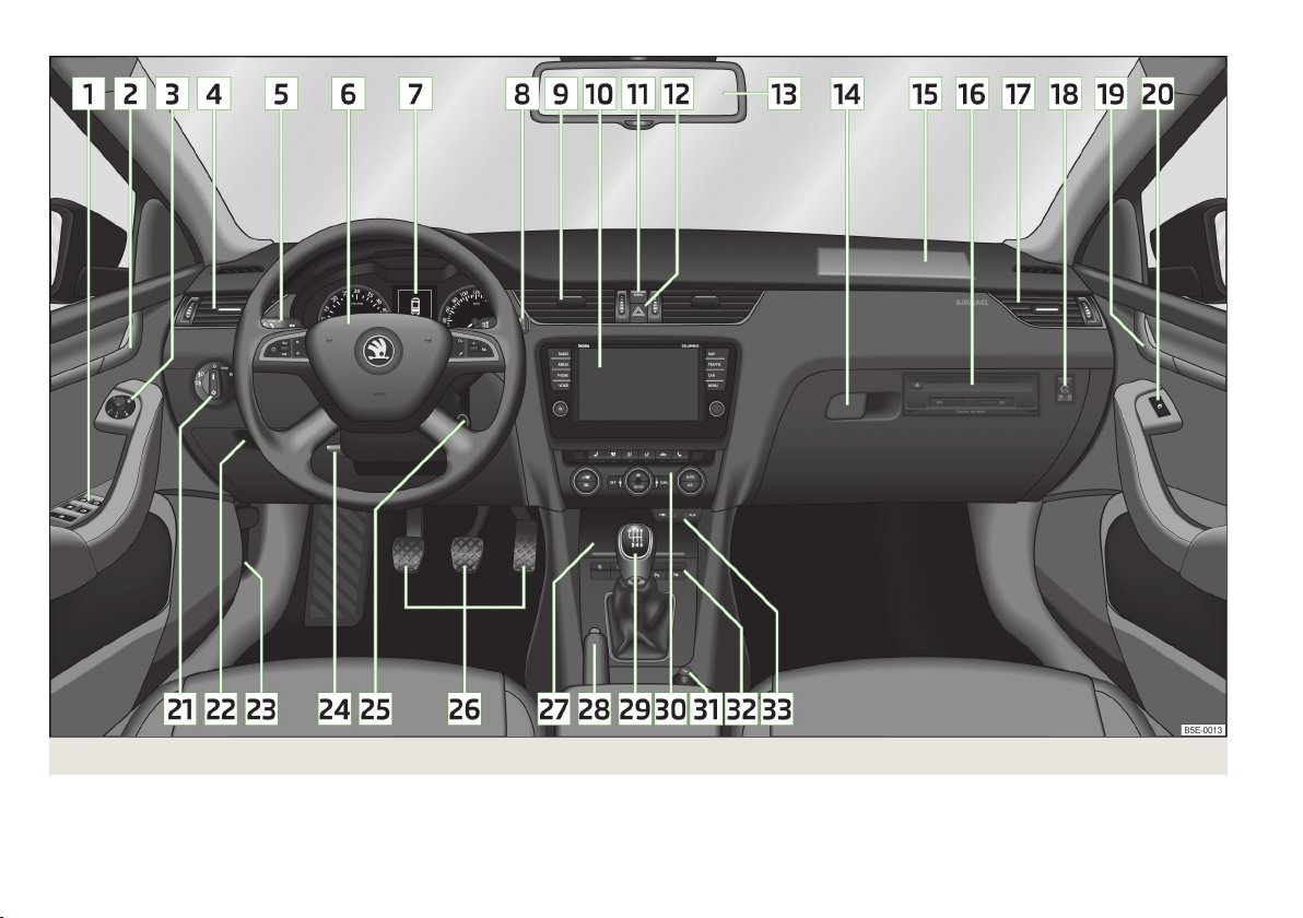
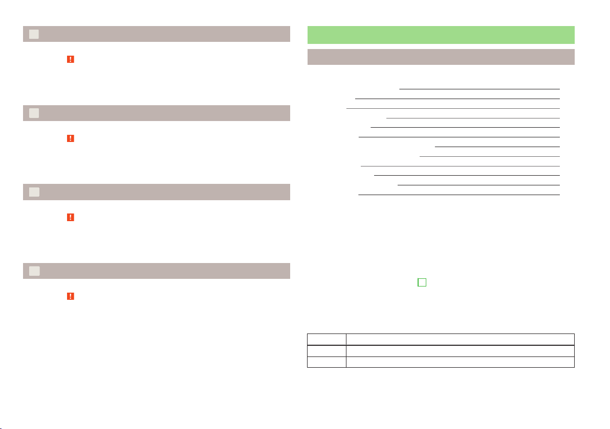
Fig. 1
6
Using the system
Cockpit
Using the system
Cockpit
Overview
1
Electrical power windows 41
2
Door opening lever on the driver's side 34
3
Electric exterior mirror adjustment 61
4
Air outlet vent on the driver's side 96
5
Operating lever:
Turn signal light, headlight and parking light, headlight flasher 49
›
Speed regulating system 139
›
6
Steering wheel:
With horn
›
With driver’s front airbag
›
With buttons for the Infotainment system 107
›
7
Instrument cluster
8
Operating lever:
Windscreen wiper and wash system 58
›
Multifunction display
›
Information display 24
›
9
Air outlets in the middle part of the dash panel
10
Infotainment » owner's manual for the Infotainment radio or navigation
11
Warning light for the deactivated front seat passenger airbag
12
Switch for hazard warning lights 53
13
Interior rear-view mirror
14
Storage compartment on the front passenger side
15
Front passenger airbag 169
16
CD/DVD drive and memory card slot (in the passenger-side storage
compartment) » owner's manual for the Infotainment radio and/or
navigation
17
Air outlet vent on the front passenger side
18
Key switch for switching off the front passenger airbag (in front
passenger storage compartment) 173
19
Door opening lever on the front passenger side 34
20
Power window in the front passenger door 42
21
Light switch 48
22
Storage compartment on the driver's side 71
Fuse box (behind the storage compartment on the driver's side) 231
23
Bonnet release lever 195
24
Lever for adjusting the steering wheel 113
25
Ignition lock 114
26
Pedals 120
27
Storage compartment 72
28
Handbrake lever 119
29
Depending on equipment fitted:
Gearshift lever (manual gearbox) 120
›
Selector lever (automatic gearbox) 121
›
30
Depending on equipment fitted:
Operating controls for the heating 97
›
Operating controls for the air conditioning system
›
Operating controls for Climatronic 101
169
8
25
96
173
61
75
›
31
Depending on equipment fitted:
12-Volt power socket
›
Cigarette lighter 73
›
32
Bar with keys depending on the equipment fitted:
Central locking system
›
START STOP 141
›
Traction control TCS 132
›
Electronic Stability Control ESC 131
›
Selection of driving mode
›
Park Assist 135
›
Parking aid 133
›
Tyre inflation pressure calibration
›
33
Depending on equipment fitted:
USB/AUX input 107
›
MEDIA IN input 107
›
Note
The arrangement of the controls and switches and the location of some items on
96
right-hand drive models may differ from that shown in » Fig. 1. The symbols on
the controls and switches are the same as for left-hand drive models.
99
74
33
143
210
Cockpit
7
Instruments and warning lights
Instrument cluster
Introduction
This chapter contains information on the following subjects:
Overview
Revolutions counter 9
Display 9
Speedometer 9
Coolant temperature display 10
Fuel gauge 10
Counter for distance driven
Setting the time 11
Viewing the charge level vehicle battery
Service interval display
Auto-check control 12
Component protection
If the message SAFE CP appears in the instrument cluster display, the component
protection for the instrument cluster is active. Further information » page 189,
Component protection.
Seek help from a ŠKODA specialist garage.
Fault display
If there is a fault in the instrument cluster, the following message will appear in
the display.
Error: Instrument cluster. Workshop!
COMBIINSTRUM_WORKSHOP
Seek help from a ŠKODA specialist garage.
WARNING
■
Concentrate fully at all times on your driving! As the driver you are fully re-
sponsible for the operation of your vehicle.
■
Never operate the button 6 in the instrument cluster » Fig. 2 on page 8
while driving, only when the vehicle is stationary!
Overview
8
11
11
11
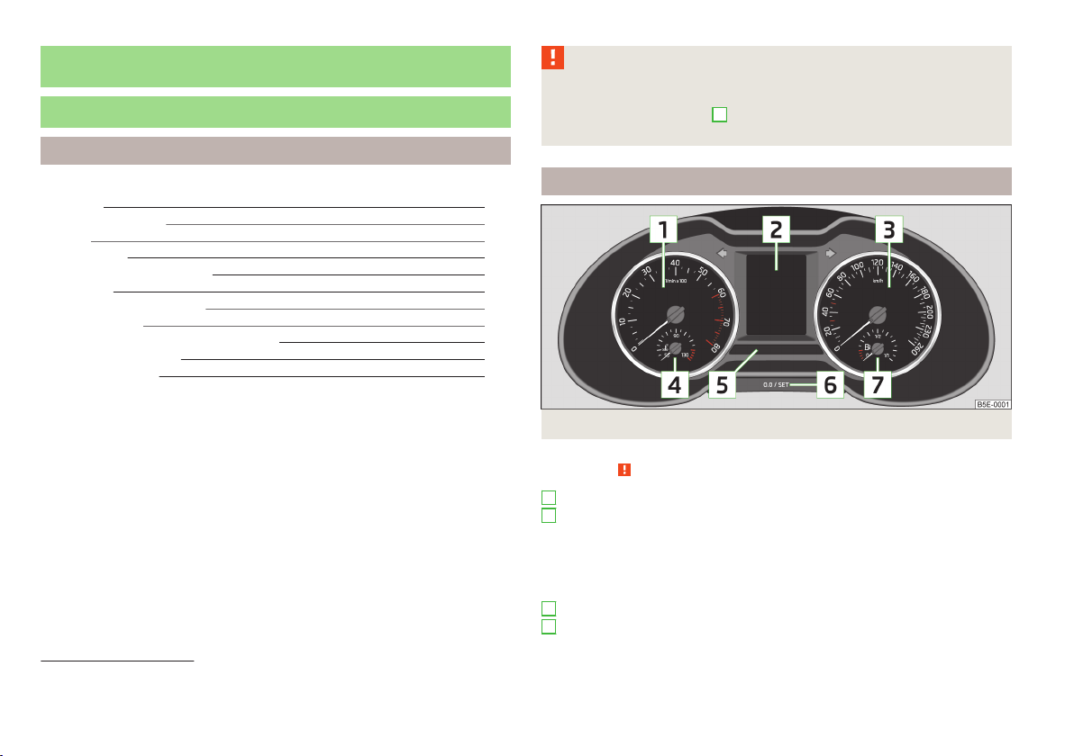
Fig. 2
Instrument cluster
First read and observe the introductory information and safety warnings on page 8.
1
Revolutions counter with warning lights » page 9
2
Display » page 9
With counter for distance driven » page 11
›
With service interval display » page 11
›
With digital clock » page 11
›
With information system » page 23
›
With control symbols » page 18
›
3
Speedometer1) with warning lights » page 9
4
Coolant temperature gauge » page 10
1)
During the journey, the speed can be displayed in a different unit (mph or km/h) in addition to the
tachometer display.
8
Using the system
5
Bar with warning lights » page 12
6
Button for:
Set hours/minutes » page 11
›
Displaying the distance and days until the next service inter-
›
val » page 11
Resetting Service Interval Display » page 11
›
Reset trip counter for the distance driven » page 11
›
Charge level indicator » page 11
›
7
Fuel gauge » page 10
Revolutions counter
First read and observe the introductory information and safety warnings on page 8.
The red scale of the rev counter 1 » Fig. 2 on page 8 indicates the range in which
the system begins to limit the engine speed. The system automatically restricts
the engine speed to a steady limit.
You should shift into the next higher gear before the red scale of the revolution
counter is reached, or select mode D on the automatic gearbox.
Follow the recommended gear to prevent engine speeds that are too high or too
low » page 23.
Display
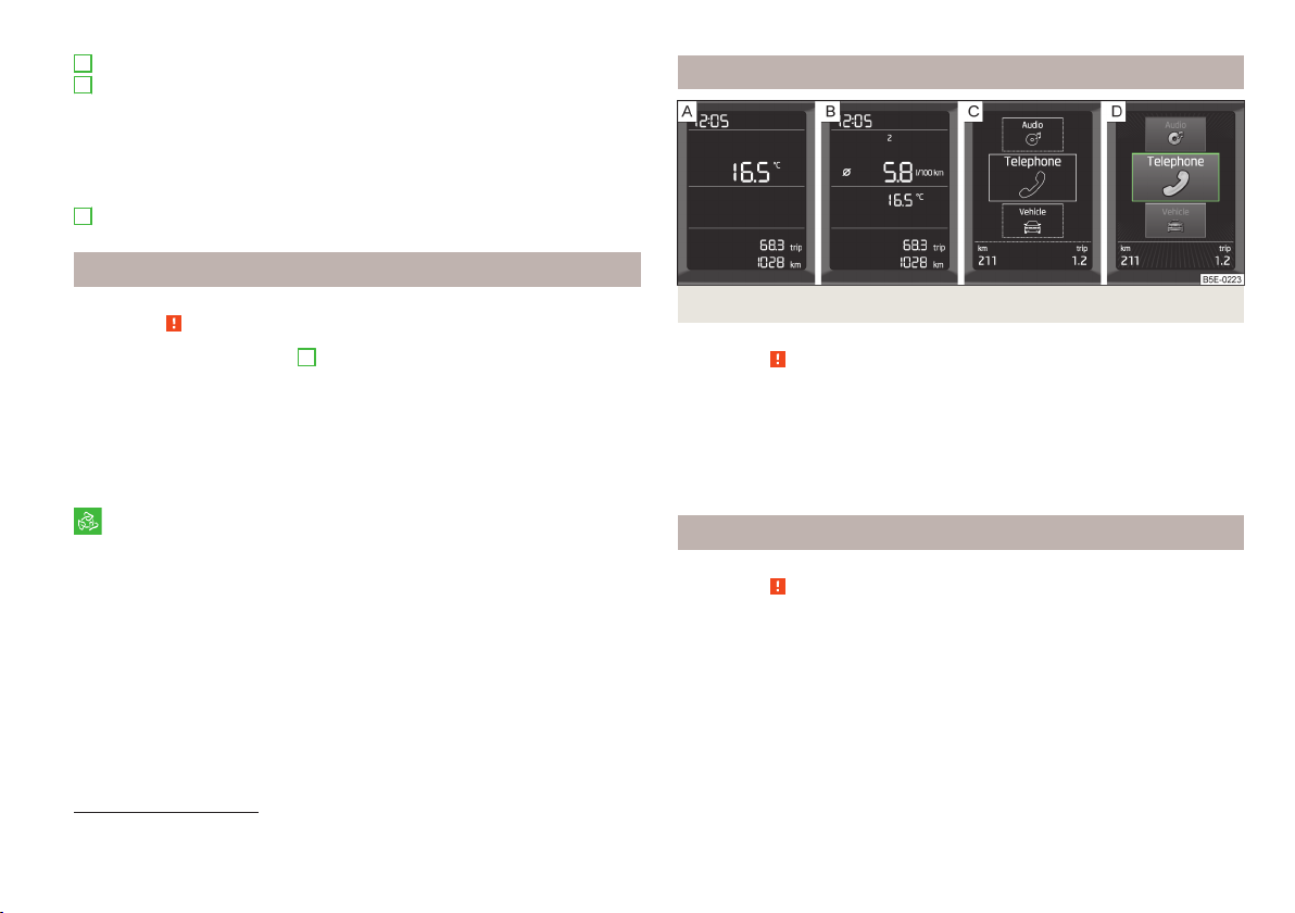
Fig. 3 Display types
First read and observe the introductory information and safety warnings
The instrument cluster can have one of the following types of display » Fig. 3.
Segment display without multi function display
Segment display with multi-function display
Monochromatic information display
Colour information display
on page 8.
For the sake of the environment
Correct shifting up has the following advantages.
■
It helps to reduce fuel consumption.
■
It reduces the operating noise.
■
It protects the environment.
■
It benefits the durability and reliability of the engine.
1)
This function only applies to certain countries.
Speedometer
First read and observe the introductory information and safety warnings
Warning against excessive speeds
An audible warning signal will sound when the vehicle speed exceeds 120 km/h1).
The audible warning signal is switched off when the vehicle speed falls below
120 km/h.
on page 8.
Instruments and warning lights
9

Coolant temperature display
Fuel gauge
Fig. 4
Coolant temperature gauge
First read and observe the introductory information and safety warnings on page 8.
The coolant temperate display » Fig. 4 only operates when the ignition is switched on.
Cold range
If the pointer is still in the left area of the scale it means that the engine has not
yet reached its operating temperature. Avoid high speeds, full throttle and high
engine loads. This prevents possible damage to the engine.
The operating range
The engine has reached its operating temperature as soon as the pointer moves
into the mid-range of the scale. At very high ambient temperatures or heavy engine loads, the pointer may move even further to the right.
High temperature range
If the pointer reaches the red area of the scale, the coolant temperature is too
high. Further information » page 19.
CAUTION
Additional headlights and other attached components in front of the air inlet impair the cooling efficiency of the coolant.
Fig. 5
Fuel gauge
First read and observe the introductory information and safety warnings on page 8.
The fuel gauge » Fig. 5 only operates if the ignition is switched on.
The fuel tank has a capacity of about 50 litres. If the pointer reaches the reserve
marking (red area of the scale), the control indicator » page 21 lights up.
CAUTION
Never drive until the fuel tank is completely empty! The irregular supply of fuel
can cause misfiring, which can result in considerable damage to parts of the engine and exhaust system.
Note
The arrow next to the icon within the fuel gauge displays the installation location of the fuel filler on the right side of the vehicle.
10
Using the system
Counter for distance driven
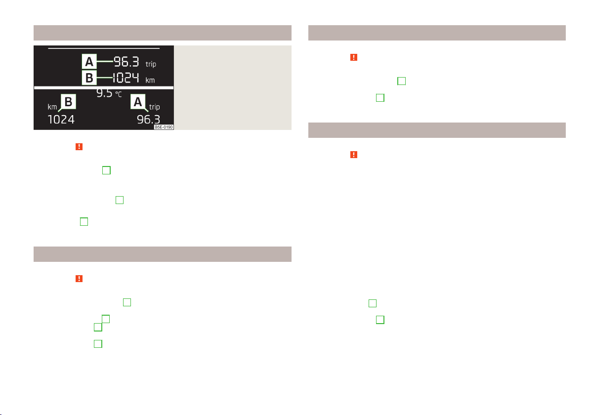
Fig. 6
Segment display/information
display
Viewing the charge level vehicle battery
First read and observe the introductory information and safety warnings on page 8.
Switch off the ignition.
›
Press and hold the button 6 » Fig. 9 on page 26 until the Battery status or
›
BATTERY is shown in the display.
Release the button
›
played in %.
6
- the current charge level of the vehicle battery is dis-
First read and observe the introductory information and safety warnings on page 8.
Daily trip counter (trip)
The daily trip counter A » Fig. 6 shows the distance driven since the time the
counter was last reset - in steps of 100 m.
Reset trip counter for the distance driven
Briefly press the button 6 » Fig. 2 on page 8.
›
Odometer
The odometer
driven.
B
» Fig. 6 indicates the total distance which the vehicle has been
Setting the time
First read and observe the introductory information and safety warnings on page 8.
Switch on the ignition.
›
Press and hold the button 6 » Fig. 2 on page 8 until the Time is shown in the
›
display.
Release the button 6, and the system switches to the time setting function.
›
Press the button 6 again and set the hours.
›
Wait around 4 seconds - the system switches to the minutes setting.
›
Press the button 6 again and set the minutes.
›
The time can also be set in the Infotainment » operating instructions for Infotainment, chapter Unit setup.
Service interval display
First read and observe the introductory information and safety warnings on page 8.
Service message
Before reaching the service interval, the icon appears in the display after the
ignition is switched on, together with the message.
Service in ... km or ... day(s).
SERVICE IN... km OR ... DAYS
The kilometre indicator or the days indicator reduces in steps of 100 km or, where
applicable, days until the service due date is reached.
Once the service interval is reached, the icon appears in the display after the
ignition is switched on, together with the message.
Service now!
SERVICE NOW
Displaying the distance and days until the next service interval
Switch on the ignition.
›
Press the button
›
appears.
Release the button
›
The icon appears in the display together with the message.
Service in ... km or ... day(s).
SERVICE IN... km OR ... DAYS
6
» Fig. 2 on page 8 and keep it pressed down until Service
6
.
Instruments and warning lights
11
Resetting Service Interval Display
If the variable service interval is set in your vehicle and if the service interval display is reset, the variable service interval is switched to the fixed service interval.
Only the “Oil Change Service” indication is reset, the “Inspection” indication is not
reset.
We therefore recommend that the Service Interval Display be reset only by a
ŠKODA Partner, who will reset the display with a vehicle system tester.
The ŠKODA Partner will carry out the following steps.
He resets the display memory after the relevant inspection.
›
He makes an entry in the service schedule.
›
He affixes a sticker with the entry of the following service interval to the side of
›
the dash panel on the driver's side.
6
The reset can be done with the button
Switch off the ignition (for vehicles with the KESSY system, also close the driv-
›
er's door).
Press the button
›
Switch on the ignition.
›
Release and then press again the button
›
6
and keep it pressed down.
» Fig. 2 on page 8.
6
.
CAUTION
We recommend that you do not reset the service interval display yourself. Incorrectly setting the service interval display could cause problems to the vehicle.
Note
■
Information is retained in the Service Interval Display even after the vehicle bat-
tery is disconnected.
■
If the instrument cluster is exchanged after a repair, the correct values must be
entered in the counter for the Service Interval Display. We recommend having this
work undertaken by a ŠKODA Partner.
■
For more information on the service intervals » service schedule, chapter service intervals.
Auto-check control
First read and observe the introductory information and safety warnings on page 8.
Certain functions and conditions of individual vehicle systems are checked continuously when the ignition is switched on.
Error messages and/or other information are displayed in the instrument cluster
display.
Some messages are displayed simultaneously with the warning lights » page 12
or warning icons in the display » page 18.
While the operational faults remain unrectified, the messages are always indicated again. After they are displayed for the first time, the symbols or continue
to be indicated without any extra messages for the driver.
Symbol Description
Warning
Danger
WARNING
If you have to stop for technical reasons, then park the vehicle at a safe distance from the traffic, switch off the engine and activate the hazard warning
light system » page 53. The warning triangle must be set up at the prescribed distance - observe the national legal provisions when doing so.
Warning lights
Introduction
This chapter contains information on the following subjects:
Clutches of the automatic gearbox too hot
Handbrake
Brake system
Front seat belt warning light
Power steering 14
Traction control system (TCS)
13
13
14
14
14
12
Using the system
Traction control system (TCS) off 15
Electronic Stability Control (ESC)
Antilock brake system (ABS) 15
Rear fog light
Exhaust inspection system 16
Glow plug system (diesel engine)
Engine performance check (petrol engine)
Safety systems
Tyre inflation pressure
Brake pad thickness 17
Lane following system (Lane Assist)
Turn signal system 17
Trailer turn signal lights
Fog lights 18
Cruise control system 18
Selector lever lock 18
Main beam
The warning lights indicate certain functions or faults.
Some warning lights can be accompanied by acoustic signals and messages in the
display of the instrument cluster.
After switching on the ignition, some warning lights illuminate briefly as a func-
tion test.
If the tested systems are OK, the corresponding warning lights go out a few sec-
onds after switching on the ignition.
The condition of some features and systems is shown by the warning icons on
the display » page 18.
The warning lights are at the following locations in the instrument cluster » Fig. 2
on page 8.
Revolutions counter
›
Speedometer
›
Bar with warning lights
›
1
3
5
15
16
16
16
16
17
17
17
18
WARNING
■
Ignoring illuminated warning lights and related messages or instructions in
the display of the instrument cluster may lead to serious personal injury or
damage to the vehicle.
■
If you have to stop for technical reasons, then park the vehicle at a safe distance from the traffic, switch off the engine and activate the hazard warning
light system » page 53. The warning triangle must be set up at the prescribed distance - observe the national legal provisions when doing so.
■
The engine compartment of your car is a hazardous area. While working in
the engine compartment, be sure to observe the following warnings » page 193, Engine compartment.
Clutches of the automatic gearbox too hot
First read and observe the introductory information and safety warnings on page 12.
The warning light lights up if the temperature of the clutches of the automatic
gearbox is too high.
The following message is shown in the information cluster display.
Gearbox overheated. Stop! Owner's manual!
STOP VEHICLE GEARBOX OVERHEAT
Stop the vehicle, switch off the engine, and wait until the light goes out – risk
of gearbox damage! You can continue your journey as soon as the light goes out.
Handbrake
First read and observe the introductory information and safety warnings on page 12.
The warning light comes on if the handbrake is applied.
An acoustic signal will sound if you drive the vehicle above 5 km/h while the
handbrake is still on.
The following message is shown in the information cluster display.
Release the handbrake!
RELEASE HANDBRAKE
Instruments and warning lights
13

Brake system
First read and observe the introductory information and safety warnings on page 12.
If the warning light lights up, the brake fluid level in the brake system is too
low.
The following message is shown in the information cluster display.
Brake fluid: owner's manual!
BRAKE FLUID PLEASE CHECK
Stop the vehicle, switch off the engine, and check the level of the brake fluid » page 201 »
If the warning light lights up together with the warning light , there is a
problem with the ABS.
.
WARNING
■
If the warning light is displayed simultaneously with warning light
» page 15, Antilock brake system (ABS), do not continue your jour-
ney! Seek help from a ŠKODA specialist garage.
■
A fault to the braking system can increase the vehicle's braking distance -
risk of accident!
Front seat belt warning light
First read and observe the introductory information and safety warnings on page 12.
The warning light comes on after the ignition is switched on as a reminder for
the driver and front passenger to fasten the seat belt.
The warning light goes out if the driver or front passenger has fastened their
seat belt.
If the driver or front passenger has not fastened their seat belt and the vehicle
speed is more than 30 km/h, the warning light flashes and you will hear an
acoustic signal.
If the seat belt is not fastened by the driver or front passenger during the next
approx. 2 seconds, the warning signal is deactivated and the warning light
lights up permanently.
Further information » page 162, Seat belts.
Power steering
First read and observe the introductory information and safety warnings on page 12.
If the warning light lights up, this indicates a partial failure of the power steering and the steering forces can be greater. Seek help from a ŠKODA specialist garage.
If the warning light lights up, this indicates a complete failure of the power
steering and the steering assist has failed (significantly higher steering forces).
Seek help from a ŠKODA specialist garage.
Further information » page 113.
Note
If the vehicle's battery has been disconnected and reconnected, the warning light
comes on after switching on the ignition. The warning light should go out after
driving a short distance. If after a new engine start and a short ride the yellow
warning light does not go out, seek help from a ŠKODA specialist garage.
Traction control system (TCS)
First read and observe the introductory information and safety warnings
If your vehicle is equipped with the ESC system, the TCS is part of the
ESC » page 131.
The warning light flashes to show that the ASR is currently operating.
If the warning light lights up, there is a fault in the ASR.
The following message is shown in the information cluster display.
Error: traction control
ASR ERROR
Seek help from a ŠKODA specialist garage.
on page 12.
14
Using the system
If the warning light comes on after starting the engine, the TCS may be switched off for technical reasons. Switch the ignition off and on again. If the warning
light does not light up after you switch the engine back on, the TCS is fully
functional again.
Further information » page 131 and » page 132, Traction Control System (TCS).
Note
If the vehicle's battery has been disconnected and reconnected, the warning light
comes on after switching on the ignition. If the warning light does not go out
after moving a short distance, this means there is an error in the system. Seek
help from a ŠKODA specialist garage.
Traction control system (TCS) off
First read and observe the introductory information and safety warnings on page 12.
If the warning light is lit, the TCS is off.
The following message is shown in the information cluster display.
Traction control (ASR) deactivated.
ASR OFF
Further information » page 132, Traction Control System (TCS).
Electronic Stability Control (ESC)
First read and observe the introductory information and safety warnings on page 12.
A flashing warning light shows that the ESC system is currently operating.
If the warning light lights up, there is a fault in the ESC system.
The following message is shown in the information cluster display.
Error: stabilisation control (ESC)
ESC ERROR
Seek help from a ŠKODA specialist garage.
If the warning light comes on after starting the engine, the ESC system may be
switched off for technical reasons.
Switch the ignition off and on again.
›
If the warning light does not light up after you switch the engine back on, the
ESC system is fully functional again.
Further information » page 131, Electronic Stability Control (ESC).
Note
If the vehicle's battery has been disconnected and reconnected, the warning light
comes on after switching on the ignition. If the warning light does not go out
after moving a short distance, this means there is an error in the system. Seek
help from a ŠKODA specialist garage.
Antilock brake system (ABS)
First read and observe the introductory information and safety warnings on page 12.
If the warning light lights up, there is a fault in the ABS.
The following message is shown in the information cluster display.
Error: ABS
ABS ERROR
The vehicle will only be braked by the normal brake system without the ABS.
Seek help from a ŠKODA specialist garage.
Further information » page 132, Antilock Braking System (ABS).
WARNING
■
If the warning light is displayed simultaneously with warning light ,
do not continue your journey! Seek help from a ŠKODA specialist garage.
■
A fault to the ABS system or the braking system can increase the vehicle's
braking distance – risk of accident!
Instruments and warning lights
15

Rear fog light
First read and observe the introductory information and safety warnings on page 12.
The warning light comes on when the rear fog light is switched on.
Further information » page 52.
Exhaust inspection system
First read and observe the introductory information and safety warnings
If the warning light lights up, there is a fault in the exhaust inspection system.
The system allows the vehicle to run in emergency mode.
Seek help from a ŠKODA specialist garage.
Glow plug system (diesel engine)
The warning light comes on after the ignition has been switched on. Once the
light has gone out, the engine can be started immediately.
There is a fault in the glow plug system if the warning light does not come on
at all or lights up continuously.
If the warning light begins to flash while driving, a fault exists in the engine
control. The system allows the vehicle to run in emergency mode.
Seek help from a ŠKODA specialist garage.
on page 12.
First read and observe the introductory information and safety warn-
on page 12.
ings
Engine performance check (petrol engine)
First read and observe the introductory information and safety warnings on page 12.
If the warning light
allows the vehicle to run in emergency mode.
lights up, there is a fault in the engine control. The system
Seek help from a ŠKODA specialist garage.
Safety systems
First read and observe the introductory information and safety warnings on page 12.
If the warning light lights up, there is a fault in the airbag or pedestrian protection system.
Airbag system
The following message is shown in the information cluster display.
Error: Airbag
AIRBAG ERROR
The functionality of the airbag system is monitored automatically even if one of
the airbags is switched off.
One of the airbags or a belt tensioner has been disabled by the diagnostic tool
The warning light lights up for approx. 4 seconds after switching on the igni-
›
tion and then flashes again for approx. 12 seconds.
The following message is shown in the information cluster display.
›
Airbag/belt tensioner deactivated.
AIRBAG/BELT TENSIONER OFF
The front passenger airbag has been disabled with the key switch
The warning light comes on for about 4 seconds after the ignition has been
›
switched on.
The warning light
›
panel lights up after switching on the ignition » page 173.
Passenger protection system
The following message is shown in the information cluster display.
Error: pedestrian protection
PEDESTRIAN PROTECTION ERROR
Further information » page 175.
in the display
in the middle of the dash
16
Using the system
WARNING
If there is a fault in the safety system, have it checked immediately by a
ŠKODA specialist garage. Otherwise, there is a risk of the systems not being
activated in the event of an accident.
Tyre inflation pressure
First read and observe the introductory information and safety warnings on page 12.
The warning light lights up, if there is a substantial drop in inflation pressure in
one of the tyres. Check and adjust the pressure in all tyres » page 207.
An audible signal sounds as a warning signal.
If the warning light flashes, there is a fault in the system.
Seek help from a ŠKODA specialist garage.
Further information » page 210, Tyre control display.
Note
If the vehicle's battery has been disconnected and reconnected, the warning light
comes on after switching on the ignition. If the warning light does not go out
after moving a short distance, this means there is an error in the system. Seek
help from a ŠKODA specialist garage.
Brake pad thickness
First read and observe the introductory information and safety warnings on page 12.
If the indicator light is lit, the brake pads are worn.
The following message is shown in the information cluster display.
Check brake wear!
BRAKE PADS PLEASE CHECK
Seek help from a ŠKODA specialist garage.
Lane following system (Lane Assist)
First read and observe the introductory information and safety warnings on page 12.
The warning lights indicates the state of the Lane Assist system.
Further information » page 146.
Turn signal system
First read and observe the introductory information and safety warnings
Either the left or right indicator light flashes depending on the position of
the control lever.
If there is a fault in the turn signal system, the warning light flashes at twice its
normal rate. This does not apply when towing a trailer.
Switching off the hazard warning light system is switched on will cause all of the
turn signal lights as well as both warning lights to flash.
Further information » page 49, Turn signal and main beam.
Trailer turn signal lights
if the warning light flashes, the trailer turn signal lights are turned on.
If a trailer is hitched and the warning light is not flashing, one of the trailer turn
signal lights has failed.
The following message is shown in the information cluster display, for example.
Trailer: check left turn signal!
TRAILER TURN SIG_ CHECK LEFT
The trailer must be unhitched properly » page 152, Towing a trailer.
on page 12.
First read and observe the introductory information and safety warnings on page 12.
Instruments and warning lights
17
Fog lights
First read and observe the introductory information and safety warnings on page 12.
The warning light comes on when the fog lights are operating.
Further information » page 52.
Cruise control system
First read and observe the introductory information and safety warnings
The warning light comes on when the cruise control is active.
Further information » page 139.
Selector lever lock
If the warning light lights up, operate the brake pedal.
Further information » page 121.
Main beam
The warning light comes on when the main beam is selected or when the
headlight flasher is operated.
Further information » page 49.
on page 12.
First read and observe the introductory information and safety warnings on page 12.
First read and observe the introductory information and safety warnings on page 12.
Warning icons in the display
Introduction
This chapter contains information on the following subjects:
Rear seat belt warning 19
Alternator 19
Coolant
Engine oil pressure
Engine oil level
Bulb failure 20
Diesel particle filter (diesel engine) 21
Windscreen washer fluid level 21
Fuel reserve
Headlight assist 22
START-STOP system 22
Ice warning 22
The warning icons indicate the status of certain functions or faults.
The warning icons are indicated in the display of the instrument cluster » page 9.
After switching on the ignition, some warning icons illuminate briefly as a func-
tion test.
If the tested systems are OK, the corresponding warning icons go out a few seconds after switching on the ignition.
Depending on the meaning of the warning icon, the icon or will also light up
in the bar with the warning lights
Some warning icons can be accompanied by acoustic signals and messages in the
instrument cluster display.
The status of some features and systems is shown by the warning
lights » page 12.
Symbol
5
» Fig. 2 on page 8.
Description
Warning
Danger
19
20
20
21
18
Using the system
While the operational faults remain unrectified, the messages are always indicated again. After they are displayed for the first time, the symbols or continue
to be indicated without any extra messages for the driver.
On vehicles with a colour information display » Fig. 3 on page 9 - , some warning icons in the display are in colour.
WARNING
■
Ignoring illuminated warning icons and related messages or instructions in
the display of the instrument cluster may lead to serious personal injury or
damage to the vehicle.
■
If you have to stop for technical reasons, then park the vehicle at a safe distance from the traffic, switch off the engine and activate the hazard warning
light system » page 53. The warning triangle must be set up at the prescribed distance - observe the national legal provisions when doing so.
■
The engine compartment of your car is a hazardous area. While working in
the engine compartment, be sure to observe the following warnings » page 193, Engine compartment.
Rear seat belt warning
First read and observe the introductory information and safety warnings on page 18.
A rear seat belt is not fastened
A rear seat belt is fastened
The warning icons or come on after the ignition has been switched on.
When the seat belt is fastened/unfastened, the particular icon lights up briefly
and indicates the current belt status!
Further information » page 162, Seat belts.
Alternator
First read and observe the introductory information and safety warnings on page 18.
The warning icon lights up if the vehicle battery is not charged when the engine is running.
Seek help from a ŠKODA specialist garage.
CAUTION
If the icon (cooling system fault) comes on in addition to the icon when driving, stop the vehicle immediately and switch off the engine – risk of engine damage!
Coolant
First read and observe the introductory information and safety warnings on page 18.
Coolant level too low
If the coolant level is too low, the warning icon lights up and the following
message appears in the instrument cluster display.
Check coolant! Owner's manual!
ENGINE COOLANT PLEASE CHECK
Stop the vehicle, switch off the engine, and check the coolant level » page 200.
›
If the coolant level is too low, add coolant to the reservoir » page 201.
›
If, after adding coolant and switching on the ignition, the warning icon disap-
›
pears, you can continue your journey.
If the coolant level is within the specified range, but the warning icon is still
›
lit, check the fuse for the radiator fan and replace it if necessary » page 233,
Fuses in the engine compartment.
If the coolant level and fan fuse are in order, but the warning icon is still lid,
›
do not continue your journey!
Seek help from a ŠKODA specialist garage.
›
Coolant temperature too high
If the coolant temperature is too high, the warning icon lights up and the following message appears in the instrument cluster display.
Engine overheat. Stop! Owner's manual!
ENGINE OVERHEAT STOP
Stop the vehicle and turn off the engine.
›
Wait until the coolant temperature gauge pointer returns to the operating
›
range » page 10.
Continue your journey only after the warning icon has disappeared.
›
Instruments and warning lights
19

WARNING
■
Carefully open the coolant expansion bottle. If the engine is hot, the cooling
system is pressurized – risk of scalding! It is therefore best to allow the engine
to cool down before removing the cap.
■
Do not touch the radiator fan. The radiator fan may switch itself on automatically even if the ignition is off.
Engine oil pressure
First read and observe the introductory information and safety warnings on page 18.
When the warning icon flashes, the engine oil pressure is too low.
The following message is shown in the information cluster display.
Oil pressure: Stop! Owner's manual!
STOP VEHICLE OIL PRESSURE
Stop the vehicle, switch off the engine, and check the level of the engine
oil » page 198, Checking the oil level.
Even if the oil level is correct, do not drive any further if the warning icon is
flashing! Also do not leave the engine running at an idling speed.
Seek help from a ŠKODA specialist garage.
Engine oil level
First read and observe the introductory information and safety warnings on page 18.
Engine oil level too low
If the warning icons and are lit, the engine oil level is too low.
The following message is shown in the information cluster display.
Oil level: top up oil!
TOP UP OIL
Stop the vehicle, switch off the engine, and check the level of the engine
oil » page 198.
The warning icon will go out if the bonnet is left open for more than 30 seconds.
If no engine oil has been replenished, the warning icon will come on again after
driving about 100 km.
Engine oil level too high
If the warning icons and are lit in conjunction with the following message on
the display, the engine oil level is too high.
Reduce oil level!
OIL LEVEL TOO HIGH
Stop the vehicle, switch off the engine, and check the level of the engine
oil » page 198.
Engine oil level sensor
If the warning icons and are lit in conjunction with the following message on
the display, the engine oil level sensor is defective.
Oil sensor: Workshop!
OIL SENSOR WORKSHOP
Seek help from a ŠKODA specialist garage.
WARNING
Do not continue your journey if for some reason it is not possible to top up
the engine oil under the prevailing conditions! Switch off the engine and seek
assistance from a ŠKODA specialist garage.
Bulb failure
First read and observe the introductory information and safety warnings on page 18.
The warning icon comes on if a bulb is faulty.
The following message is shown in the information cluster display, for example.
Check right dipped headlight beam!
DIPPED HEADLIGHT CHECK RIGHT
20
Using the system
Diesel particle filter (diesel engine)
First read and observe the introductory information and safety warnings on page 18.
The diesel particulate filter separates the soot particles from the exhaust. The
soot particles collect in the diesel particulate filter where they are burnt on a reg-
ular basis.
If the warning icon lights up, soot has accumulated in the diesel particulate
filter.
To clean the diesel particle filter, and where traffic conditions permit »
for at least 15 minutes or until the warning icon goes out as follows.
4th or 5th gear selected (automatic gearbox: Position D/S).
›
Vehicle speed at least 60 km/h.
›
Engine speed between 1800-2500 rpm.
›
If the filter is properly cleaned, the warning icon goes out.
If the filter is not properly cleaned, the warning icon does not go out and the
warning icon begins to flash.
The following message is shown in the information cluster display.
Diesel particulate filter: owner's manual!
DIESEL PM FILTER OWNER MANUAL
Seek help from a ŠKODA specialist garage.
, drive
WARNING
■
The diesel particle filter achieves very high temperatures. Therefore do not
park in areas where the hot filter can come into direct contact with dry grass
or other combustible materials – there is the risk of fire!
■
Always adjust your speed to suit weather, road, region and traffic conditions. The recommendations indicated by the warning light must not tempt
you to disregard the national regulations for road traffic.
CAUTION
■
As long as the warning icon lights up, you must take into account an increased fuel consumption and in certain circumstances a power reduction of the
engine.
■
Using diesel fuel with an increased sulphur content can considerably reduce the
life of the diesel particle filter. A ŠKODA specialist garage will be able to tell you
which countries use only diesel fuel with high sulphur content.
Note
■
We encourage you to avoid constant short journeys. This will improve the combustion process of the soot particles in the diesel particulate filter.
■
If the engine is turned off during the filter cleaning process or shortly afterwards, the cooling fan may turn on automatically for a few minutes.
Windscreen washer fluid level
First read and observe the introductory information and safety warnings on page 18.
If the windscreen washer fluid level is too low, the warning icon comes on.
The following message is shown in the information cluster display.
Top up washer fluid!
WASHER FLUID PLEASE TOP UP
Top up with liquid » page 196.
Fuel reserve
First read and observe the introductory information and safety warnings on page 18.
If the warning icon comes on, there is a fuel reserve of under about 7 litres left.
The following message is shown in the information cluster display.
Please refuel. Range: ... km
PLEASE REFUEL
An audible signal sounds as a warning signal.
Instruments and warning lights
21

Note
The text in the display goes out after refuelling and driving a short distance.
Headlight assist
First read and observe the introductory information and safety warnings on page 18.
The warning icon is lit when the headlight assist is activated.
Further information » page 51, Headlight assist.
START-STOP system
First read and observe the introductory information and safety warnings
The warning icons indicate the state of the START-STOP system.
Further information » page 141.
Ice warning
The warning icon draws your attention to the risk of ice.
Further information » page 23.
on page 18.
First read and observe the introductory information and safety warnings on page 18.
22
Using the system
Information system
Driver information system
Introduction
This chapter contains information on the following subjects:
Information on the display
Outside temperature 23
Recommended gear 23
Door, boot or bonnet warning 24
Eco tips 24
Information display 24
Information on the display
First read and observe the introductory information given on page 23.
The information system provides the driver with alerts and messages about individual vehicle systems. These alerts and messages appear in the display of the instrument cluster 2 » Fig. 2 on page 8 (hereafter only in the display).
The information system provides the following information.
Outside temperature » page 23.
›
Recommended gear » page 23.
›
Door, boot lid and bonnet warning » page 24.
›
Eco tips » page 24.
›
Service interval display » page 11.
›
Auto Check Control » page 12.
›
Warning icons » page 18.
›
Driving data (multifunction display) » page 25.
›
Warning against excessive speeds » page 27.
›
Details of the information display » page 24.
›
Traffic sign recognition » page 149.
›
Fatigue detection » page 151.
›
Selector lever positions for an automatic gearbox » page 121.
›
Information and alerts in the Assist systems » page 131.
›
Outside temperature
First read and observe the introductory information given on page 23.
The current outside temperature is shown in the display.
If the outside temperature drops below +4 °C while driving, the following symbol
(warning signal for ice on the road) appears before the temperature indicator
and an audible signal will sound.
23
If the outside temperature is less than +4 °C when the ignition is turned on, the
following symbol appears in the display and an acoustic signal sounds.
After pressing the rocker switch
page 26, the function shown last is indicated.
WARNING
Even at temperatures around +4 °C, black ice may still be on the road surface!
Do not only rely upon the information given on the outside temperature dis-
play that there is no ice on the road.
A
or the adjustment wheel D » Fig. 9 on
Recommended gear
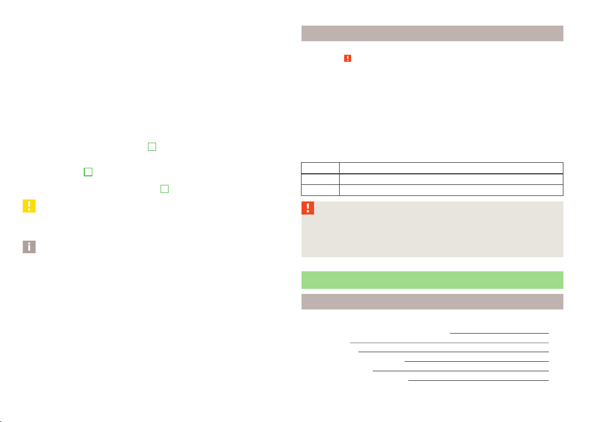
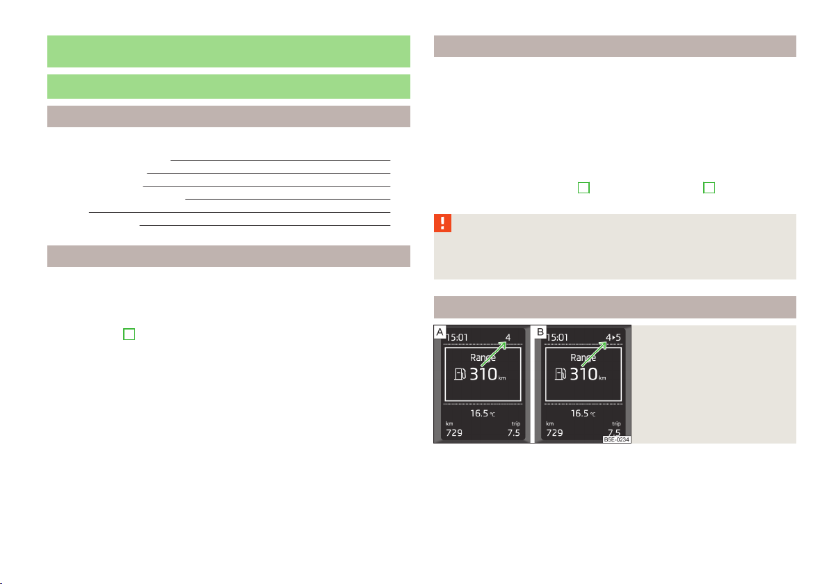
Fig. 7
Recommended gear
First read and observe the introductory information given on page 23.
In order to minimise the fuel consumption, a recommendation for shifting into another gear is indicated in the display.
Information about the currently-selected gear is shown in the upper part of the
display » Fig. 7 - .
Information system
23
When the system determines that a change in gear is required, the arrow symbol
and the recommended gear appear next to the current gear indication » Fig. 7 .
For instance, if appears in this display, this means it is recommended that
you shift from 4th into 5th. gear.
WARNING
The driver is always responsible for selecting the correct gear in different driving situations, such as overtaking.
Information display
Door, boot or bonnet warning
First read and observe the introductory information given on page 23.
If at least one door is open, or the boot or bonnet is open, the display indicates
the relevant open door or boot/bonnet.
An acoustic signal will also sound if you drive the vehicle above 6 km/h.
Eco tips
First read and observe the introductory information given on page 23.
To minimise fuel consumption, fuel economy tips can appear in the display.
Eco tips are indicated next to the letters ECO-TIP.
For instance, if the air-condition is on and a window is open, the following mes-
sage appears ECO TIP Air conditioning switched on: close windows.
Eco tips display must be activated in the Infotainment » operating instructions for
Infotainment, chapter Vehicle settings (CAR button).
24
Using the system
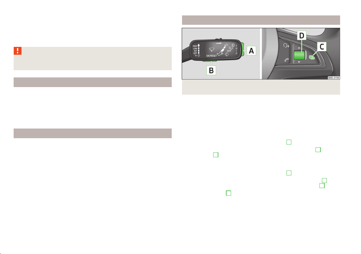
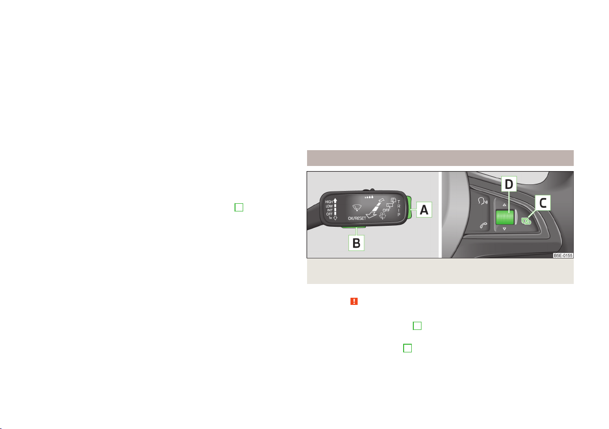
Fig. 8 Buttons (adjustment wheel) on the operating lever/multifunction
steering wheel
First read and observe the introductory information given on page 23.
The information display provides you with information on the current operating
state of your vehicle. The information display also provides you with data (depending on the equipment installed in the vehicle) relating to the Infotainment,
multi-functional indicator, etc.
Operating with the buttons on the operating lever
Activate the Main menu by pressing the rocker switch
Individual menu items can be selected by means of the rocker switch A. When
the pushbutton
played.
Operating the button/adjustment wheel on the multifunction steering wheel
Activate the Main menu by pressing the rocker switch C » Fig. 8 for longer.
The individual menus can be selected by pressing the adjustment wheel
selected menu is displayed after briefly pressing the adjustment wheel D.
By briefly pressing the C button you will reach one level higher.
Main menu points
The following information can be selected (depending on the equipment installed
on the vehicle).
■
Driving data » page 25
■
Assist systems » page 146
B
is briefly pressed, the information you have selected is dis-
A
» Fig. 8 for longer.
D
. The
■
Navigation » operating instructions for Infotainment, chapter Navigation system (NAV button)
■
Audio » operating instructions for Infotainment, chapter Media (MEDIA button)
■
Telephone » operating instructions for Infotainment, chapter Telephone
(PHONE button)
■
Vehicle » page 12, Auto-check control
Note
If warning messages are shown in the information display, these messages must
be confirmed with the button B on the operating lever or with the adjustment
wheel D on the multifunction steering wheel » Fig. 8 to call up the main menu.
Driving data (multifunction display)
Introduction
This chapter contains information on the following subjects:
Information overview 25
Select information
Memory
Warning against excessive speeds 27
The multifunction display only operates if the ignition is switched on.
After the ignition is switched on, the function displayed is the one which you last
selected before switching off the ignition.
Individual menu items can be shown or hidden » Bedienungsanleitung Infotain-
ment, chapter Setting vehicle systems (CAR button).
WARNING
Concentrate fully at all times on your driving! As the driver you are fully responsible for the operation of your vehicle.
26
Note
In certain countries the displays appear in the Imperial system of measures.
Information overview
First read and observe the introductory information and safety warnings on page 25.
Range
The range indicates the distance you can still drive with your vehicle based on the
level of fuel in the tank and the same style of driving as before.
The display is shown in steps of 10 km. After lighting up of the warning icon the
display is shown in steps of 5 km.
The fuel consumption over the last 50 km is used to calculate the range. The
range can increase if you drive in a more fuel-efficient manner.
Average fuel consumption
The average fuel consumption1) is calculated since the last time the memory was
erased » page 27.
If you wish to determine the average fuel consumption over a certain period of
27
time, you must set the memory at the start of the new measurement to
zero » Fig. 9 on page 26.
After erasing the memory, no fuel consumption data will appear for the first
100 m driven.
The fuel consumption data is updated regularly while you are driving.
Current fuel consumption
You can use this information to adapt your driving style to the desired fuel consumption1).
The display appears in litres/hour if the vehicle is stationary or driving at a low
speed2).
1)
To set the units for the fuel consumption display » Bedienungsanleitung Infotainment, chapter Unit
setup.
2)
On some models in certain countries, the display appears in --,- kilometres/litres if the vehicle is stationary.
Information system
25
Oil temperature
If the engine oil temperature is in the range 80-110 °C, the engine operating temperature is reached.
If the temperature lies below 80 °C or above 110 °C, avoid high engine revs, full
throttle and high engine loads.
If the oil temperature is lower than 50 °C or if a fault in the system for checking
the oil temperature is present, are displayed instead of the oil temperature.
Warning against excessive speeds
Set the speed limit, for example, for the maximum permissible speed in
town » page 27.
Traffic sign recognition
Up to three detected traffic signs can be indicated in the display with the following information.
Maximum permissible speed (including additional sign).
›
Overtaking prohibited.
›
Further information » page 149, Traffic sign recognition.
Current driving speed
The current speed is identical to the display on the speedometer
page 8.
Average speed
The average speed since the memory was last erased is shown in the display
in km/hour » page 27.
To determine the average speed over a certain period of time, set the memory to
zero at the start of the measurement » page 27.
After erasing the memory, no average speed data will appear for approx. the first
300 m driven.
The average speed data is updated regularly while you are driving.
Distance travelled
The distance driven since the memory was last erased appears in the display.
If you want to measure the distance travelled from a particular moment in time
on, at this moment, reset the memory by setting the button to zero » page 27.
The maximum distance indicated is 9999 km. The indicator is automatically set
back to zero if this period is exceeded.
3
» Fig. 2 on
Driving time
The driving time which has elapsed since the memory was last erased, appears in
the display.
If you want to measure the time travelled from a particular moment in time on, at
this moment, reset the memory by setting the button to zero » page 27.
The maximum distance indicated is 99 hours and 59 minutes. The indicator is set
back to zero if this period is exceeded.
Convenience consumers
The consumption display for the convenience consumers in l/h.
Together with the consumption display, a list of three convenience consumers
with the highest consumption is also displayed.
Select information
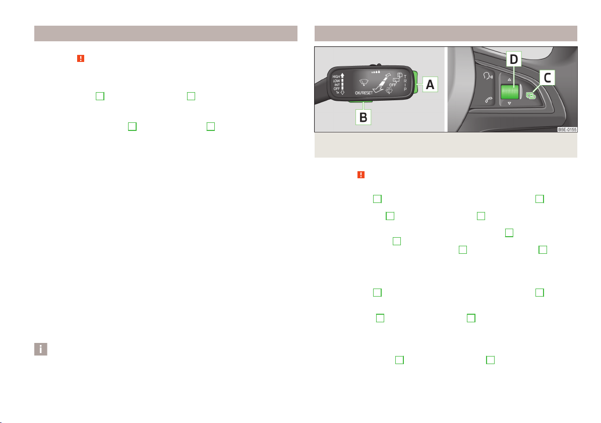
Buttons (adjustment wheel) on the operating lever/multifunction
Fig. 9
steering wheel
First read and observe the introductory information and safety warnings
Selecting using the operating lever
Briefly press the rocker switch A » Fig. 9 up or down.
›
Selecting using the multifunction steering wheel
Turn the adjustment wheel D » Fig. 9 upwards or downwards.
›
on page 25.
26
Using the system
Memory
First read and observe the introductory information and safety warnings on page 25.
The multifunction display is equipped with three automatic memories.
Select memory
Press the button B or the adjustment wheel D» Fig. 9 on page 26 briefly.
›
Resetting
Select the desired memory.
›
Press longer on the button B or adjustment wheel D » Fig. 9 on page 26.
›
The following values of the selected memory are set to zero.
Average fuel consumption.
›
Distance driven.
›
Average speed.
›
Driving time
›
Since start
The memory collates the driving information from the moment the ignition is
switched on until it is switched off.
New data will also flow into the calculation of the current driving information if
the trip is continued within 2 hours after switching off the ignition.
If the trip is interrupted for more than 2 hours, the memory is automatically
erased.
Long-term
The memory gathers driving information from any number of individual journeys
up to a total of 99 hours and 59 minutes driving or 9999 kilometres driven.
The memory is deleted when either of these limits is reached and the calculation
starts all over again.
Since refuel
The memory gathers driving information since the last refuelling.
The memory is erased automatically the next time you fill up.
Note
Disconnecting the vehicle battery will delete all memory data.
Warning against excessive speeds
Fig. 10 Buttons (adjustment wheel) on the operating lever/multifunction
steering wheel
First read and observe the introductory information and safety warnings on page 25.
Adjust the speed limit while the vehicle is stationary
With the button A » Fig. 10 or, if applicable, the adjustment wheel D, select
›
the menu item Warning against excessive speeds.
Pressing the button B or the adjustment wheel D activates the setup mode
›
for the speed limit.
Set the desired speed limit, e.g. 50 km/h, with the button A or, if applicable,
›
the adjustment wheel D.
Confirm the speed limit by pressing button B, or adjustment wheel D or wait
›
around 5 seconds. Your settings are saved automatically.
This allows you to set the speed in 5 km/h intervals.
Adjusting the speed limit while the vehicle is moving
With the button
›
the menu item Warning against excessive speeds.
Drive at the desired speed, e.g. 50 km/h.
›
Press the button B or the adjustment wheel D to accept the current speed as
›
the speed limit (the value flashes).
If you wish to change the set speed limit, it is changed in 5 km/h intervals (e.g. the
accepted speed of 47 km/h increases to 50 km/h or decreases to 45 km/h).
Press again the button B or the adjustment wheel D to confirm the speed lim-
›
it, or wait approx. 5 seconds and the setting is saved automatically (the value
stops flashing).
A
» Fig. 10 or, if applicable, the adjustment wheel D, select
Information system
27

Change or delete speed limit
With the button A » Fig. 10 or, if applicable, the adjustment wheel D, select
›
the menu item Warning against excessive speeds.
Pressing the button B or the adjustment wheel D deletes the speed limit.
›
Pressing the button B or the adjustment wheel D again activates change
›
mode for the speed limit.
If the pre-set speed is exceeded, an acoustic signal appears as a warning tone
and a warning message appears in the display, e.g.
Speed 50 exceeded.
SPEED TOO HIGH
The set speed limit value remains stored even after switching off the ignition. After a gap between driving exceeding 2 hours, the pre-set speed limit is deleted.
28
Using the system
 Loading...