

SKODA Fabia II 2007, Fabia II 2009, Fabia II 2011, Octavia II 2004, Octavia II 2010 Workshop Manual
...
Service
GETtheMANUALS.org
Workshop Manual
Fabia II 2007 ➤ , Fabia II 2009 ➤ ,
Fa
Octavia II 2010 ➤ , Rapid NH 2013 ➤ ,
Roomster 2006 ➤ , Yeti 2010 ➤ ,
Yeti 2011 ➤
bia II 2011 ➤ , Octavia II 2004 ➤ ,
1,2/63; 77 kW TSI engine
Engine ID
CBZACBZ
B
Edition 09.2012
Service Department. Technical Information

Service
GETtheMANUALS.org
List of Workshop Manual Repair GroupsList of Workshop Manual
Repair GroupsList of Workshop Manual Repair Groups
Re
pa ir G ro up
00 - Technical data
01 - Self-diagnosis
10 - Removing and installing engine
13 - Crankshaft group
15 - Cylinder head, valve gear
17 - Lubrication
19 - Cooling
20 - Fuel supply system
21 - Turbocharging/supercharging
24 - Mixture preparation - injection
26 - Exhaust system
28 - Ignition system

Fabia II 2007 ➤ , Fabia II 2009 ➤ , Fabia II 2011 ➤ , Octavia II 2004 ➤ ...
GETtheMANUALS.org
1,2/63; 77 kW TSI engine - Edition 09.2012
Contents
00 - Technical data
1 Technical data
1.1 Engine number . . . . . . . . . . . . . . . . . . . . . . . . . . . . . . . . . . . . . . . . . . . . . . . . . . . . . . . . . . 1
1.2 Engine characteristics . . . . . . . . . . . . . . . . . . . . . . . . . . . . . . . . . . . . . . . . . . . . . . . . . . . . 1
01 - Self-diagnosis
1 Self diagnosis, safety measures, cleanliness regulations, directions
1.1 Self-diagnosis . . . . . . . . . . . . . . . . . . . . . . . . . . . . . . . . . . . . . . . . . . . . . . . . . . . . . . . . . . . . 3
1.2 Regulations concerning safety precautions when working on the fuel system . . . . . . . . . . 3
1.3 Release pressure in the high pressure area of the fuel system . . . . . . . . . . . . . . . . . . . . . . 4
1.4 Rules of cleanliness to observe when working on the fuel supply system . . . . . . . . . . . . . . 5
1.5 Safety measures to apply when working on the fuel injection and ignition system . . . . . . 6
1.6 General notes on the injection system . . . . . . . . . . . . . . . . . . . . . . . . . . . . . . . . . . . . . . . . 7
1.7 General notes on the ignition system . . . . . . . . . . . . . . . . . . . . . . . . . . . . . . . . . . . . . . . . . . 7
1.8 General instructions for charge air system . . . . . . . . . . . . . . . . . . . . . . . . . . . . . . . . . . . . . . 8
1.9 Additional instructions when undertaking assembly work on the air-conditioning system . . 9
10 - Removing and installing engine
1 Removing and installing engine
1.1 Removing engine . . . . . . . . . . . . . . . . . . . . . . . . . . . . . . . . . . . . . . . . . . . . . . . . . . . . . . . . 10
1.2 Removing engine . . . . . . . . . . . . . . . . . . . . . . . . . . . . . . . . . . . . . . . . . . . . . . . . . . . . . . . . 15
1.3 Securing the engine to the assembly stand . . . . . . . . . . . . . . . . . . . . . . . . . . . . . . . . . . . . 22
1.4 Installing the engine . . . . . . . . . . . . . . . . . . . . . . . . . . . . . . . . . . . . . . . . . . . . . . . . . . . . . . 23
2 Assembly bracket . . . . . . . . . . . . . . . . . . . . . . . . . . . . . . . . . . . . . . . . . . . . . . . . . . . . . . . . 27
2.1 Assembly bracket . . . . . . . . . . . . . . . . . . . . . . . . . . . . . . . . . . . . . . . . . . . . . . . . . . . . . . . . 27
2.2 Unit mounting - summary of components . . . . . . . . . . . . . . . . . . . . . . . . . . . . . . . . . . . . . . 28
2.3 Checking and adjusting the assembly bracket . . . . . . . . . . . . . . . . . . . . . . . . . . . . . . . . . . 29
. . . . . . . . . . . . . . . . . . . . . . . . . . . . . . . . . . . . . . . . . . . . . . . . . . . . 1
. . . . . . . . . . . . . . . . . . . . . . . . . . . . . . . . . . . . . . . . . . . . . . . . . . . . . . . . . . 1
. . . . . . . . . . . . . . . . . . . . . . . . . . . . . . . . . . . . . . . . . . . . . . . . . . . . 3
. . . . . . . . . . . . . . . . . . 3
. . . . . . . . . . . . . . . . . . . . . . . . . . . . . . . . . . . . . . 10
. . . . . . . . . . . . . . . . . . . . . . . . . . . . . . . . . . . . . . . . . . . . . . 10
13 - Crankshaft group
1 V-ribbed belt drive
1.1 V-ribbed belt - Summary of components . . . . . . . . . . . . . . . . . . . . . . . . . . . . . . . . . . . . . . 32
1.2 Removing and installing V-ribbed belt . . . . . . . . . . . . . . . . . . . . . . . . . . . . . . . . . . . . . . . . 35
1.3 Removing and installing bracket for top auxiliary units . . . . . . . . . . . . . . . . . . . . . . . . . . . . 36
1.4 Removing and installing bracket for bottom auxiliary units . . . . . . . . . . . . . . . . . . . . . . . . 38
2 Camshaft drive . . . . . . . . . . . . . . . . . . . . . . . . . . . . . . . . . . . . . . . . . . . . . . . . . . . . . . . . . . 40
2.1 Camshaft drive - Summary of components . . . . . . . . . . . . . . . . . . . . . . . . . . . . . . . . . . . . 40
2.2 Removing and installing the top timing case . . . . . . . . . . . . . . . . . . . . . . . . . . . . . . . . . . . . 43
2.3 Removing and installing the bottom timing case . . . . . . . . . . . . . . . . . . . . . . . . . . . . . . . . 45
3 Sealing flanges and flywheel . . . . . . . . . . . . . . . . . . . . . . . . . . . . . . . . . . . . . . . . . . . . . . . . 48
3.1 Summary of components . . . . . . . . . . . . . . . . . . . . . . . . . . . . . . . . . . . . . . . . . . . . . . . . . . 48
3.2 Removing and installing flywheel . . . . . . . . . . . . . . . . . . . . . . . . . . . . . . . . . . . . . . . . . . . . 49
3.3 Replacing crankshaft seal on belt pulley side . . . . . . . . . . . . . . . . . . . . . . . . . . . . . . . . . . 50
3.4 Removing and installing crankshaft-belt pulley . . . . . . . . . . . . . . . . . . . . . . . . . . . . . . . . . . 51
3.5 Replace sealing flange on the gearbox side . . . . . . . . . . . . . . . . . . . . . . . . . . . . . . . . . . . . 55
4 Crankshaft . . . . . . . . . . . . . . . . . . . . . . . . . . . . . . . . . . . . . . . . . . . . . . . . . . . . . . . . . . . . . . 61
4.1 Replace needle bearing for crankshaft . . . . . . . . . . . . . . . . . . . . . . . . . . . . . . . . . . . . . . . . 61
5 Pistons and conrods . . . . . . . . . . . . . . . . . . . . . . . . . . . . . . . . . . . . . . . . . . . . . . . . . . . . . . 63
5.1 Summary of components . . . . . . . . . . . . . . . . . . . . . . . . . . . . . . . . . . . . . . . . . . . . . . . . . . 63
5.2 Inspect piston, piston rings and cylinder bore . . . . . . . . . . . . . . . . . . . . . . . . . . . . . . . . . . 64
5.3 Separating new conrod . . . . . . . . . . . . . . . . . . . . . . . . . . . . . . . . . . . . . . . . . . . . . . . . . . . . 66
. . . . . . . . . . . . . . . . . . . . . . . . . . . . . . . . . . . . . . . . . . . . . . . . . . 32
. . . . . . . . . . . . . . . . . . . . . . . . . . . . . . . . . . . . . . . . . . . . . . . . . . . . . . . . 32
15 - Cylinder head, valve gear
. . . . . . . . . . . . . . . . . . . . . . . . . . . . . . . . . . . . . . . . . . 67
Contents i

Fabia II 2007 ➤ , Fabia II 2009 ➤ , Fabia II 2011 ➤ , Octavia II 2004 ➤ ...
GETtheMANUALS.org
1,2/63; 77 kW TSI engine - Edition 09.2012
1 Cylinder head - part 1
1.1 Summary of components . . . . . . . . . . . . . . . . . . . . . . . . . . . . . . . . . . . . . . . . . . . . . . . . . . 67
1.2 Test timing . . . . . . . . . . . . . . . . . . . . . . . . . . . . . . . . . . . . . . . . . . . . . . . . . . . . . . . . . . . . . . 69
1.3 Setting the timing . . . . . . . . . . . . . . . . . . . . . . . . . . . . . . . . . . . . . . . . . . . . . . . . . . . . . . . . 71
1.4 Removing and installing timing chain and drive chain for oil pump . . . . . . . . . . . . . . . . . . 77
2 Cylinder head - part 2 . . . . . . . . . . . . . . . . . . . . . . . . . . . . . . . . . . . . . . . . . . . . . . . . . . . . . . 84
2.1 Removing and installing cylinder head cover and camshaft . . . . . . . . . . . . . . . . . . . . . . . . 84
2.2 Removing and installing the cylinder head . . . . . . . . . . . . . . . . . . . . . . . . . . . . . . . . . . . . . . 98
2.3 Testing the compression . . . . . . . . . . . . . . . . . . . . . . . . . . . . . . . . . . . . . . . . . . . . . . . . . . 100
2.4 Testinf the combustion chamber for tightness . . . . . . . . . . . . . . . . . . . . . . . . . . . . . . . . . . 101
3 Valve gear . . . . . . . . . . . . . . . . . . . . . . . . . . . . . . . . . . . . . . . . . . . . . . . . . . . . . . . . . . . . . . 103
3.1 Valve gear - Summary of components . . . . . . . . . . . . . . . . . . . . . . . . . . . . . . . . . . . . . . . . 103
3.2 inspect camshaft, axial play . . . . . . . . . . . . . . . . . . . . . . . . . . . . . . . . . . . . . . . . . . . . . . . . 104
3.3 Inspect valve guides . . . . . . . . . . . . . . . . . . . . . . . . . . . . . . . . . . . . . . . . . . . . . . . . . . . . . . 104
3.4 Replacing valve stem seals . . . . . . . . . . . . . . . . . . . . . . . . . . . . . . . . . . . . . . . . . . . . . . . . 105
17 - Lubrication
1 Lubrication system
1.1 Summary of components . . . . . . . . . . . . . . . . . . . . . . . . . . . . . . . . . . . . . . . . . . . . . . . . . . 108
1.2 Removing and installing oil pan . . . . . . . . . . . . . . . . . . . . . . . . . . . . . . . . . . . . . . . . . . . . . . 110
1.3 Removing and installing oil pump . . . . . . . . . . . . . . . . . . . . . . . . . . . . . . . . . . . . . . . . . . . . 112
1.4 Removing and installing engine oil cooler . . . . . . . . . . . . . . . . . . . . . . . . . . . . . . . . . . . . . . 113
1.5 Testing oil pressure and oil pressure switch F1 . . . . . . . . . . . . . . . . . . . . . . . . . . . . . . . . 114
. . . . . . . . . . . . . . . . . . . . . . . . . . . . . . . . . . . . . . . . . . . . . . . . . . . . . . 107
. . . . . . . . . . . . . . . . . . . . . . . . . . . . . . . . . . . . . . . . . . . . . . . . . . . . . . 67
. . . . . . . . . . . . . . . . . . . . . . . . . . . . . . . . . . . . . . . . . . . . . . . . . . . . . . . . 107
19 - Cooling
1 Cooling system
1.1 Connection diagram for coolant hoses . . . . . . . . . . . . . . . . . . . . . . . . . . . . . . . . . . . . . . . . 116
1.2 Connection diagram for coolant hoses . . . . . . . . . . . . . . . . . . . . . . . . . . . . . . . . . . . . . . . . 117
1.3 Draining and filling up coolant . . . . . . . . . . . . . . . . . . . . . . . . . . . . . . . . . . . . . . . . . . . . . . 118
2 Parts of cooling system engine side . . . . . . . . . . . . . . . . . . . . . . . . . . . . . . . . . . . . . . . . . . 123
2.1 Coolant regulator - Summary of components . . . . . . . . . . . . . . . . . . . . . . . . . . . . . . . . . . . . 123
2.2 Removing and installing belt pulley for coolant pump . . . . . . . . . . . . . . . . . . . . . . . . . . . . 123
2.3 Removing and installing coolant pump . . . . . . . . . . . . . . . . . . . . . . . . . . . . . . . . . . . . . . . . 124
2.4 Removing and installing coolant recirculation pump V50 . . . . . . . . . . . . . . . . . . . . . . . . . . 125
3 Radiator and radiator fan . . . . . . . . . . . . . . . . . . . . . . . . . . . . . . . . . . . . . . . . . . . . . . . . . . 126
3.1 Parts of cooling system on the side next to the body - Summary of components . . . . . . . . 126
3.2 Parts of cooling system on the side next to the body - Summary of components . . . . . . . . 128
3.3 Removing and installing fan shroud for radiator fan V7 . . . . . . . . . . . . . . . . . . . . . . . . . . 131
3.4 Removing and installing fan shroud for radiator fan . . . . . . . . . . . . . . . . . . . . . . . . . . . . . . 132
3.5 Removing and installing radiator . . . . . . . . . . . . . . . . . . . . . . . . . . . . . . . . . . . . . . . . . . . . 133
3.6 Removing and installing radiator . . . . . . . . . . . . . . . . . . . . . . . . . . . . . . . . . . . . . . . . . . . . 135
3.7 Checking the coolant system for leaktightness . . . . . . . . . . . . . . . . . . . . . . . . . . . . . . . . . . 136
20 - Fuel supply system
1 Fuel tank and fuel delivery unit
1.1 Fuel tank - Summary of components . . . . . . . . . . . . . . . . . . . . . . . . . . . . . . . . . . . . . . . . . . 139
1.2 Fuel tank - Summary of components . . . . . . . . . . . . . . . . . . . . . . . . . . . . . . . . . . . . . . . . . . 141
1.3 Fuel tank version I. - Summary of components . . . . . . . . . . . . . . . . . . . . . . . . . . . . . . . . . . 144
1.4 Fuel tank version Il. - Summary of components . . . . . . . . . . . . . . . . . . . . . . . . . . . . . . . . . . 145
1.5 Fuel filter - Summary of components . . . . . . . . . . . . . . . . . . . . . . . . . . . . . . . . . . . . . . . . . . 148
1.6 Extract fuel from the fuel tank . . . . . . . . . . . . . . . . . . . . . . . . . . . . . . . . . . . . . . . . . . . . . . . . 148
1.7 Removing and installing the fuel tank . . . . . . . . . . . . . . . . . . . . . . . . . . . . . . . . . . . . . . . . . . 150
1.8 Removing and installing fuel tank version I. . . . . . . . . . . . . . . . . . . . . . . . . . . . . . . . . . . . . 153
1.9 Removing and installing fuel tank version Il. . . . . . . . . . . . . . . . . . . . . . . . . . . . . . . . . . . . . 155
1.10 Removing and installing fuel delivery unit . . . . . . . . . . . . . . . . . . . . . . . . . . . . . . . . . . . . . . 158
. . . . . . . . . . . . . . . . . . . . . . . . . . . . . . . . . . . . . . . . . . . . . . . . . . . . . . . . . . 116
. . . . . . . . . . . . . . . . . . . . . . . . . . . . . . . . . . . . . . . . . . . . . . . . . . . . . . . . . . 116
. . . . . . . . . . . . . . . . . . . . . . . . . . . . . . . . . . . . . . . . . . . . . . . . 139
. . . . . . . . . . . . . . . . . . . . . . . . . . . . . . . . . . . . . . . . . . . . . . 139
ii Contents

Fabia II 2007 ➤ , Fabia II 2009 ➤ , Fabia II 2011 ➤ , Octavia II 2004 ➤ ...
GETtheMANUALS.org
1,2/63; 77 kW TSI engine - Edition 09.2012
1.11 Removing and installing fuel delivery unit version I.
1.12 Removing and installing fuel delivery unit version Il. . . . . . . . . . . . . . . . . . . . . . . . . . . . . . . 162
1.13 Removing and installing the sender for fuel gauge display G . . . . . . . . . . . . . . . . . . . . . . 165
1.14 Testing fuel pump . . . . . . . . . . . . . . . . . . . . . . . . . . . . . . . . . . . . . . . . . . . . . . . . . . . . . . . . 166
1.15 Removing and installing fuel gauge sender -2- G169 - fuel tank version Il. . . . . . . . . . . . . 184
1.16 Removing and installing suction jet pump - fuel tank version Il. . . . . . . . . . . . . . . . . . . . . . . 186
2 Separating quick couplings . . . . . . . . . . . . . . . . . . . . . . . . . . . . . . . . . . . . . . . . . . . . . . . . 187
3 Electronic Engine Power Control (Electronic throttle) . . . . . . . . . . . . . . . . . . . . . . . . . . . . 191
3.1 Accelerator pedal module - Summary of components . . . . . . . . . . . . . . . . . . . . . . . . . . . . 191
3.2 Accelerator pedal module - Summary of components . . . . . . . . . . . . . . . . . . . . . . . . . . . . 191
3.3 Removing and installing accelerator pedal module . . . . . . . . . . . . . . . . . . . . . . . . . . . . . . 192
4 Activated charcoal container system . . . . . . . . . . . . . . . . . . . . . . . . . . . . . . . . . . . . . . . . . . 195
4.1 Activated charcoal container system - Summary of components . . . . . . . . . . . . . . . . . . . . 195
4.2 Activated charcoal container system - Summary of components . . . . . . . . . . . . . . . . . . . . 196
4.3 Activated charcoal container system - Summary of components . . . . . . . . . . . . . . . . . . . . 197
4.4 Checking the fuel tank venting . . . . . . . . . . . . . . . . . . . . . . . . . . . . . . . . . . . . . . . . . . . . . . 197
4.5 Checking the fuel tank venting . . . . . . . . . . . . . . . . . . . . . . . . . . . . . . . . . . . . . . . . . . . . . . 198
21 - Turbocharging/supercharging
1 Exhaust gas turbocharger
1.1 Exhaust turbocharger - Summary of components . . . . . . . . . . . . . . . . . . . . . . . . . . . . . . . . 201
1.2 Removing and installing exhaust gas turbocharger . . . . . . . . . . . . . . . . . . . . . . . . . . . . . . 203
2 Charge air system with exhaust gas turbocharger . . . . . . . . . . . . . . . . . . . . . . . . . . . . . . . . 208
2.1 Charge air system - Summary of components . . . . . . . . . . . . . . . . . . . . . . . . . . . . . . . . . . 208
2.2 Charge air system - Summary of components . . . . . . . . . . . . . . . . . . . . . . . . . . . . . . . . . . 209
2.3 Removing and installing charge air cooler . . . . . . . . . . . . . . . . . . . . . . . . . . . . . . . . . . . . . . 211
. . . . . . . . . . . . . . . . . . . . . . . . . . . . . . . . . . . . . . . . 201
. . . . . . . . . . . . . . . . . . . . . . . . . . . . . . . . . . . . . . . . . . . . . . . . . . 201
. . . . . . . . . . . . . . . . . . . . . . . . . . . . . . 160
24 - Mixture preparation - injection
1 Fitting location of the injection system
1.1 Fitting location of the injection system . . . . . . . . . . . . . . . . . . . . . . . . . . . . . . . . . . . . . . . . 213
1.2 Fitting location of the injection system . . . . . . . . . . . . . . . . . . . . . . . . . . . . . . . . . . . . . . . . 214
2 Intake manifold and fuel distributor . . . . . . . . . . . . . . . . . . . . . . . . . . . . . . . . . . . . . . . . . . 217
2.1 Intake manifold - Summary of components . . . . . . . . . . . . . . . . . . . . . . . . . . . . . . . . . . . . 217
2.2 Removing and installing the throttle valve control unit J338 . . . . . . . . . . . . . . . . . . . . . . . . 220
2.3 Clean throttle valve control unit J338 . . . . . . . . . . . . . . . . . . . . . . . . . . . . . . . . . . . . . . . . 222
2.4 Removing and installing intake manifold . . . . . . . . . . . . . . . . . . . . . . . . . . . . . . . . . . . . . . 223
3 Air filter . . . . . . . . . . . . . . . . . . . . . . . . . . . . . . . . . . . . . . . . . . . . . . . . . . . . . . . . . . . . . . . . 225
3.1 Air filter - Summary of components . . . . . . . . . . . . . . . . . . . . . . . . . . . . . . . . . . . . . . . . . . 225
3.2 Air filter - Summary of components . . . . . . . . . . . . . . . . . . . . . . . . . . . . . . . . . . . . . . . . . . 225
3.3 Removing and installing air filter . . . . . . . . . . . . . . . . . . . . . . . . . . . . . . . . . . . . . . . . . . . . 226
3.4 Removing and installing air filter . . . . . . . . . . . . . . . . . . . . . . . . . . . . . . . . . . . . . . . . . . . . 227
4 High pressure pump . . . . . . . . . . . . . . . . . . . . . . . . . . . . . . . . . . . . . . . . . . . . . . . . . . . . . . 229
4.1 High pressure pump - Summary of components . . . . . . . . . . . . . . . . . . . . . . . . . . . . . . . . 229
4.2 Removing and installing the high pressure pump . . . . . . . . . . . . . . . . . . . . . . . . . . . . . . . . 230
5 Injection valves . . . . . . . . . . . . . . . . . . . . . . . . . . . . . . . . . . . . . . . . . . . . . . . . . . . . . . . . . . 233
5.1 Removing and installing injection valves . . . . . . . . . . . . . . . . . . . . . . . . . . . . . . . . . . . . . . 233
5.2 Replace Teflon gasket ring and supporting washer at injection valve . . . . . . . . . . . . . . . . 235
6 Testing components . . . . . . . . . . . . . . . . . . . . . . . . . . . . . . . . . . . . . . . . . . . . . . . . . . . . . . 239
6.1 Check fuel pressure sender G247 . . . . . . . . . . . . . . . . . . . . . . . . . . . . . . . . . . . . . . . . . . . . 239
7 Engine control unit . . . . . . . . . . . . . . . . . . . . . . . . . . . . . . . . . . . . . . . . . . . . . . . . . . . . . . . . 242
7.1 Removing and installing engine control unit J623 . . . . . . . . . . . . . . . . . . . . . . . . . . . . . . . . 242
7.2 Removing and installing engine control unit J623 . . . . . . . . . . . . . . . . . . . . . . . . . . . . . . . . 243
. . . . . . . . . . . . . . . . . . . . . . . . . . . . . . . . . . . . . . . . 213
. . . . . . . . . . . . . . . . . . . . . . . . . . . . . . . . . . . . . . . . 213
26 - Exhaust system
. . . . . . . . . . . . . . . . . . . . . . . . . . . . . . . . . . . . . . . . . . . . . . . . . . 245
Contents iii

Fabia II 2007 ➤ , Fabia II 2009 ➤ , Fabia II 2011 ➤ , Octavia II 2004 ➤ ...
GETtheMANUALS.org
1,2/63; 77 kW TSI engine - Edition 09.2012
1 Removing and installing parts of the exhaust system
1.1 Catalytic converter and component parts - Summary of components . . . . . . . . . . . . . . . . 245
1.2 Catalytic converter and component parts - Summary of components . . . . . . . . . . . . . . . . 246
1.3 Middle and rear silencer - Summary of components . . . . . . . . . . . . . . . . . . . . . . . . . . . . . . 248
1.4 Middle and rear silencer - Summary of components . . . . . . . . . . . . . . . . . . . . . . . . . . . . . . 249
1.5 Middle and rear silencer - Summary of components . . . . . . . . . . . . . . . . . . . . . . . . . . . . . . 250
1.6 Middle and rear silencer for vehicles manufactured up to 06.10 - Summary of components
. . . . . . . . . . . . . . . . . . . . . . . . . . . . . . . . . . . . . . . . . . . . . . . . . . . . . . . . . . . . . . . . . . . . . . . . 251
1.7 Middle and rear silencer for vehicles manufactured as of 06.10 - Summary of components
. . . . . . . . . . . . . . . . . . . . . . . . . . . . . . . . . . . . . . . . . . . . . . . . . . . . . . . . . . . . . . . . . . . . . . . . 252
1.8 Removing and installing catalytic converter with pre-exhaust pipe . . . . . . . . . . . . . . . . . . 253
1.9 Replacing middle or rear silencer . . . . . . . . . . . . . . . . . . . . . . . . . . . . . . . . . . . . . . . . . . . . 255
1.10 Aligning exhaust system free of stress . . . . . . . . . . . . . . . . . . . . . . . . . . . . . . . . . . . . . . . . 256
1.11 Inspecting the exhaust system for leaktightness . . . . . . . . . . . . . . . . . . . . . . . . . . . . . . . . 257
28 - Ignition system
1 Ignition system
1.1 Ignition system - Summary of components . . . . . . . . . . . . . . . . . . . . . . . . . . . . . . . . . . . . 259
1.2 Removing and installing engine speed sender G28 . . . . . . . . . . . . . . . . . . . . . . . . . . . . . . 260
. . . . . . . . . . . . . . . . . . . . . . . . . . . . . . . . . . . . . . . . . . . . . . . . . . . . 259
. . . . . . . . . . . . . . . . . . . . . . . . . . . . . . . . . . . . . . . . . . . . . . . . . . . . . . . . . . 259
. . . . . . . . . . . . . . . . . . . . . . . . . . . . 245
iv Contents
Fabia II 2007 ➤ , Fabia II 2009 ➤ , Fabia II 2011 ➤ , Octavia II 2004 ➤ ...
GETtheMANUALS.org
1,2/63; 77 kW TSI engine - Edition 09.2012
00 – Technical data
1 Technical data
(SRL000530; Edition 09.2012)
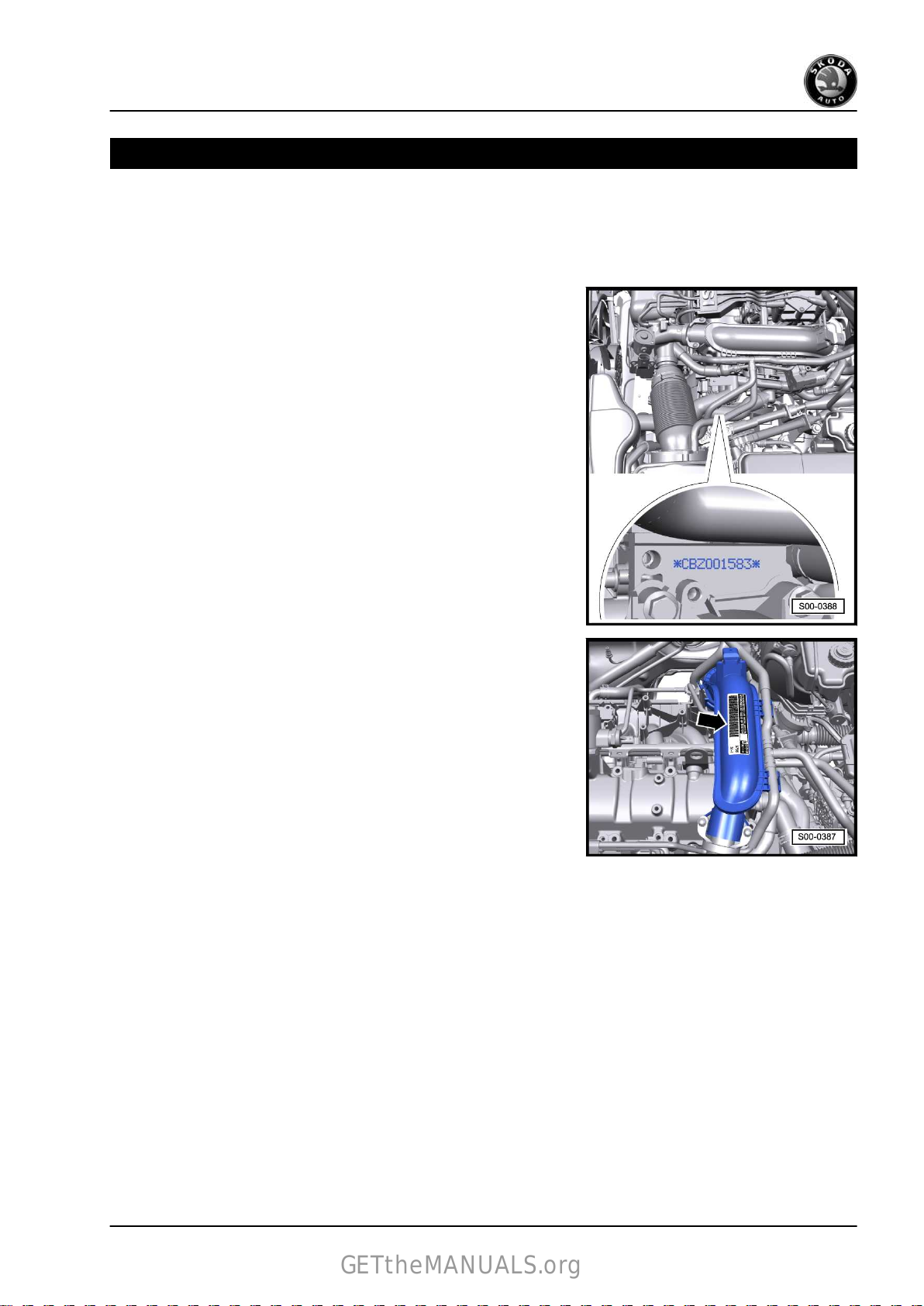
1.1 Engine number
The engine number (“engine identification characters” and “serial
number”) is located on the engine closely above the connection
of the engine with the gearbox.
In addition, the “engine identification characters” and the “serial
number”
located on the air guide pipe.
♦ The engine identification characters have 4 digits starting with
♦ The first 3 digits of the engine identification characters refer to
♦ The 4th digit refers to the output and torque of the engine and
are indicated on the vehicle data sticker -arrow- which is
the letter “C”.
the displacement and the mechanical construction of the en‐
gine. They are type-punched in the cylinder block including the
serial number.
depends upon the engine control unit.
1.2 Engine characteristics
Edition: 07.2012
Version: 3.0
1. Technical data 1

Fabia II 2007 ➤ , Fabia II 2009 ➤ , Fabia II 2011 ➤ , Octavia II 2004 ➤ ...
GETtheMANUALS.org
1,2/63; 77 kW TSI engine - Edition 09.2012
Engine identification characters CBZA CBZB
Manufactured Fabia II 03.10 ► ----
Exhaust limit values conforming to EU5 EU5
Displacement
Power output kW at rpm 63/4800 77/5000
Torque Nm at rpm 160/1500-3500 175/1550-4100
Bore ∅ mm 71,0 71,0
Stroke mm 75,6 75,6
Compression ratio 10:1 10:1
Cylinder / valves per cylinder 4 / 2 4 / 2
RON
Ignition system, fuel injection Simos 10 Simos 10
Type of fuel preparation Direct injection homogeneous Direct injection homogeneous
Knock control 1 sensor 1 sensor
Lambda control 2 Lambda probes 2 Lambda probes
Three-way catalytic converter yes yes
Exhaust gas recirculation no no
Intake manifold change-over no no
Camshaft adjustment no no
Secondary air system no no
Exhaust gas turbocharger yes yes
Balancing shaft no no
Roomster 03.10 ► ---Octavia II ---- 02.10 ►
Yeti ---- 09.09 ►
Rapid NH 07.12 ► 07.12 ►
cm
3
1197 1197
unleaded 95
1)
unleaded 95
1)
1)
At least 91 RON in exceptional cases, although engine output
is reduced
2 Rep. gr.00 - Technical data

Fabia II 2007 ➤ , Fabia II 2009 ➤ , Fabia II 2011 ➤ , Octavia II 2004 ➤ ...
GETtheMANUALS.org
1,2/63; 77 kW TSI engine - Edition 09.2012
01 – Self-diagnosis
1 Self diagnosis, safety measures,
cleanliness regulations, directions
1.1 Self-diagnosis
This Rep.-Gr. is deleted.
For this use the “Vehicle self-diagnosis”, “Measuring method” and
“Fault finding” ⇒ Vehicle diagnostic tester.
1.2 Regulations concerning safety precau‐
tions when working on the fuel system
WARNING
♦ The safety measures for the pressure reduction in the high
pressure area of the fuel system must be observed
⇒ page 4 .
♦ The fuel system is under pressure! Wear safety goggles
and safety clothing, in order to avoid injuries and skin con‐
tact with fuel. Place a clean cleaning cloth around the
connection point before detaching wiring. Reduce pres‐
sure by carefully removing the wiring.
For vehicles Fabia II, Roomster, Rapid NH
♦ The fuel delivery unit is activated when the ignition is switched
on and by the door contact switch of the driver door. Before
opening
is not disconnected, the plug -2- must be disconnected from
the fuel pump control unit.
For the vehicles Octavia II, Yeti
the fuel system and for reasons of safety, if the battery
1. Self diagnosis, safety measures, cleanliness regulations, directions 3

Fabia II 2007 ➤ , Fabia II 2009 ➤ , Fabia II 2011 ➤ , Octavia II 2004 ➤ ...
GETtheMANUALS.org
1,2/63; 77 kW TSI engine - Edition 09.2012
♦ The fuel delivery unit is activated when the ignition is switched
on and by the door contact switch of the driver door. For rea‐
sons of safety, if the battery is not disconnected, the plug -3must be disconnected from the fuel pump control unit
before opening the fuel system.
Continued for all vehicles
Caution
When undertaking all assembly work, particularly in the engine
compartment due to its cramped construction, please observe
the following:
♦ Lay lines of all kinds (e.g. for fuel, hydraulic fluid, cooling
fluid and refrigerant, brake fluid, vacuum) and electrical
lines in such a way that the original line guide is re-estab‐
lished.
♦ In order to avoid damage to the cables, ensure that there
is adequate free access to all moving or hot components.
When removing and installing the fuel gauge sender or the fuel
delivery unit from a full or partly filled fuel tank, pay attention to
the following points:
♦ The extraction hose of an exhaust extraction system which is
switched on, must be positioned close to the assembly open‐
ing
of the fuel tank in order to extract the released fuel vapours,
even before the work is commenced. If no exhaust extraction
system is available, a radial fan (motor not in air flow of fan)
with a delivery volume of more than 15 m3/h must be used.
♦ Avoid skin contact with fuel!
♦ Wear fuel-resistant gloves!
-1-
1.3 Release pressure in the high pressure area of the fuel system
WARNING
♦ The injection system consists of a high pressure part
(max. pressure of 12 MPa = 120 bar) and a low pressure
part (pressure of approx. 0.6 MPa = 6 bar).
♦ Before opening the high pressure area, e.g. removing the
high pressure pump, the fuel distributor, the injection
valves, the fuel pipes or the fuel pressure sender -G247- ,
the fuel pressure in the high pressure area with a remain‐
ing pressure of approx. 0.6 MPa (6 bar) must be reduced.
The procedure for this is described below.
– Connect
geted function “remove high fuel pressure”.
– Switch off ignition.
the ⇒ Vehicle diagnostic tester and carry out the tar‐
4 Rep. gr.01 - Self-diagnosis

Fabia II 2007 ➤ , Fabia II 2009 ➤ , Fabia II 2011 ➤ , Octavia II 2004 ➤ ...
GETtheMANUALS.org
For vehicles Fabia II, Roomster, Rapid NH
– For
For the vehicles Octavia II, Yeti
safety reasons before opening the fuel system disconnect
the plug from the fuel pump control unit -2-.
1,2/63; 77 kW TSI engine - Edition 09.2012
– For
Continued for all vehicles
safety reasons before opening the fuel system disconnect
the plug from the fuel pump control unit -3-.
WARNING
The fuel lines are pressurized! Wear safety goggles and safety
clothing, in order to avoid injuries and skin contact with fuel.
Before opening the high pressure area, lay cleaning cloths
around the connection point.
– Now lay a clean cleaning cloth around the connection point
and
carefully open it up, in order to reduce the remaining pres‐
sure of approx 0.6 MPa (6 bar). Collect the fuel which flows
out.
Note
♦
Interrogate the fault memory of the engine control unit at the
end of the following work and delete all the fault entries.
♦
If the fault memory was erased, the readiness code must be
generated ⇒ Vehicle diagnostic tester.
1.4 Rules of cleanliness to observe when working on the fuel supply system
Carefully observe the following five rules for cleanliness when
working on the fuel supply/injection system:
♦ Thoroughly clean the connection points and their surroundings
before releasing.
♦ Place removed parts on a clean surface and cover. Do not use
fuzzy cloths!
♦ Carefully cover or close opened components if the repair is not
completed immediately.
♦ Only install clean parts: Remove spare parts from their wrap‐
♦ When the system is opened: Avoid using compressed air.
immediately before installing. Do not use any parts which
ping
have been stored unwrapped (e.g. in tool boxes).
Avoid moving the vehicle.
1. Self diagnosis, safety measures, cleanliness regulations, directions 5

Fabia II 2007 ➤ , Fabia II 2009 ➤ , Fabia II 2011 ➤ , Octavia II 2004 ➤ ...
GETtheMANUALS.org
1,2/63; 77 kW TSI engine - Edition 09.2012
1.5 Safety measures to apply when working on the fuel injection and ignition system
WARNING
♦ The safety measures for the pressure reduction in the high
pressure area of the fuel system must be observed
⇒ page 4 .
♦ The fuel system is under pressure! Wear safety goggles
and safety clothing, in order to avoid injuries and skin con‐
tact with fuel. Place a clean cleaning cloth around the
connection point before detaching wiring. Reduce pres‐
sure by carefully removing the wiring.
Observe the following points to prevent injury to persons and/or
damage to the injection and ignition system:
♦ Do not touch or remove ignition leads and ignition coils with
power
output stages with the engine running or at start speed.
♦ Ignition must be switched off before disconnecting and re-
connecting the cables of the fuel injection and the ignition
system as well as of the test equipment.
♦ If the engine must be operated at start speed without it starting,
as for example, when checking the compression pressure,
open lid of fuse carrier in the engine compartment and unplug
fuse for Motronic current supply relay -J271- ⇒ Current flow
diagrams, Electrical fault finding and Fitting locations.
For vehicles Fabia II, Roomster, Rapid NH
♦ The fuel delivery unit is activated when the ignition is switched
on and by the door contact switch of the driver door. Before
opening the fuel system and for reasons of safety, if the battery
is not disconnected, the plug -2- must be disconnected from
the fuel pump control unit.
For the vehicles Octavia II, Yeti
6 Rep. gr.01 - Self-diagnosis

Fabia II 2007 ➤ , Fabia II 2009 ➤ , Fabia II 2011 ➤ , Octavia II 2004 ➤ ...
GETtheMANUALS.org
1,2/63; 77 kW TSI engine - Edition 09.2012
♦ The fuel delivery unit is activated when the ignition is switched
on and by the door contact switch of the driver door. Before
opening
is not disconnected, the plug -3- must be disconnected from
the fuel pump control unit.
Continued for all vehicles
the fuel system and for reasons of safety, if the battery
Caution
When undertaking all assembly work, particularly in the engine
compartment due to its cramped construction, please observe
the following:
♦ Lay lines of all kinds (e.g. for fuel, hydraulic fluid, the active
charcoal container-unit, cooling fluid and refrigerant,
brake fluid, vacuum) and electrical lines in such a way that
the original line guide is re-established.
♦ In order to avoid damage to the cables, ensure that there
is adequate free access to all moving or hot components.
If test and measuring devices are required during test drives ob‐
serve the following:
♦ Always secure the test and measuring devices on the rear seat
and have a second person operate them there.
♦ If the test and measuring devices are operated from the pas‐
senger
the passenger airbag in the event of an accident.
seat, the passenger could be injured by the release of
1.6 General notes on the injection system
Repairing ignition ⇒ page 259 .
♦ The engine control unit is equipped with self-diagnosis. Before
repairs
memory. Also check the vacuum hoses and connections (un‐
metered air).
♦ Fuel hoses in the engine compartment must only be secured
with spring-type clips ⇒ electronic catalogue of original parts .
The use of clamp-type or screw-type clips is not allowed.
♦ A minimum voltage of 11.5 V is required for perfect functioning
of the electrical components.
♦ Do not use sealants containing silicone. Traces of silicone el‐
ements drawn in by the engine are not burnt in the engine and
damage the lambda probe.
♦ If after fault finding, repair or inspection of components the
engine starts briefly and then stops, it is possible that the im‐
mobiliser blocks the engine control unit. Then if necessary the
control unit must be adapted ⇒ Vehicle diagnostic tester.
♦ When opening the driver door the fuel pump is activated for 2
seconds in order to build up the pressure in the fuel system.
♦ Certain inspections may cause the control unit to detect and
store a fault. It is therefore necessary to interrogate the fault
memory after having completed all inspections and repairs,
and if necessary delete ⇒ Vehicle diagnostic tester.
Safety measures
and also for fault finding, first of all interrogate the fault
⇒ page 6 .
1.7 General notes on the ignition system
♦ Switch off the ignition before disconnecting and connecting the
battery, as this may damage the 4AV control unit.
1. Self diagnosis, safety measures, cleanliness regulations, directions 7

Fabia II 2007 ➤ , Fabia II 2009 ➤ , Fabia II 2011 ➤ , Octavia II 2004 ➤ ...
GETtheMANUALS.org
1,2/63; 77 kW TSI engine - Edition 09.2012
♦ The engine control unit is equipped with self-diagnosis; in‐
spect ⇒ Vehicle diagnostic tester.
♦ A minimum voltage of 11.5 V is required for perfect functioning
of the electrical components.
♦ Certain inspections may cause the control unit to detect and
store a fault. It is therefore necessary to interrogate the fault
memory after having completed all inspections and repairs,
and if necessary delete ⇒ Vehicle diagnostic tester.
♦ If after fault finding, repair or inspection of components the
engine starts briefly and then stops, it is possible that the im‐
mobiliser
control unit must be adapted ⇒ Vehicle diagnostic tester.
Safety measures
Setting data, spark plugs:
♦ ⇒ Maintenance ; Booklet Fabia II .
♦ ⇒ Maintenance ; Booklet Roomster .
♦ ⇒ Maintenance ; Booklet Octavia II .
♦ ⇒ Maintenance ; Booklet Yeti .
♦ ⇒ Maintenance ; Booklet Rapid NH
blocks the engine control unit. Then if necessary the
⇒ page 6 .
1.8 General instructions for charge air sys‐
tem
WARNING
When undertaking all assembly work, particularly in the engine
compartment due to its cramped construction, please observe
the following:
♦ Lay lines of all kinds (e.g. for fuel, hydraulic fluid, cooling
fluid and refrigerant, brake fluid, vacuum) and electrical
lines in such a way that the original line guide is re-estab‐
lished.
♦ Ensure that there is adequate free access to all moving or
hot components.
Caution
In case a mechanical damage to the exhaust gas turbocharger
is found, e.g. damage to the compressor wheel, it is not suffi‐
cient to only replace the turbocharger. In order to avoid con‐
sequential damage, perform the following tasks:
♦ Clean all oil lines.
♦ Change engine oil and oil filter.
♦ Inspect the air filter housing, the air filter element and the
intake hoses for contaminations.
♦ Inspect the whole charge-air routing and the charge air
cooler for foreign bodies.
If foreign bodies are detected in the charge air system, the
complete
the charge air cooler must also be replaced.
charge-air routing must be cleaned and if necessary
♦ The charge-air system must be tight.
8 Rep. gr.01 - Self-diagnosis

Fabia II 2007 ➤ , Fabia II 2009 ➤ , Fabia II 2011 ➤ , Octavia II 2004 ➤ ...
GETtheMANUALS.org
1,2/63; 77 kW TSI engine - Edition 09.2012
♦ Always replace self-locking nuts.
♦ Hose connections and hoses of the charge air system must
be free of oil and grease before being installed.
♦ Only use approved clamps for securing the hose connections
⇒ Electronic Catalogue of Original Parts .
♦ Use pliers for spring strap clamps to fit the spring strap clips.
♦ Before connecting the oil feed line, fill the exhaust turbocharg‐
er via the connection fitting with engine oil.
♦ After installing the turbocharger, run engine at idling speed for
about
1 minute to ensure that oil is supplied to the turbocharg‐
er.
1.9 Additional instructions when undertak‐
ing assembly work on the air-condition‐
ing system
WARNING
Do not open the refrigerant circuit of the air conditioning sys‐
tem.
Note
In order to avoid damage to the condenser as well as to the re‐
frigerant lines and hoses, ensure that the lines and hoses are not
over-tensioned, kinked or bent.
Steps which should be taken in order to remove and install the
engine without opening the refrigerant circuit:
– Remove the holding clamp(s) of the refrigerant lines.
– Remove AC compressor from the bracket
– Mount the AC compressor in such a way that the refrigerant
lines/hoses are not under tension.
⇒ page 34 .
1. Self diagnosis, safety measures, cleanliness regulations, directions 9

Fabia II 2007 ➤ , Fabia II 2009 ➤ , Fabia II 2011 ➤ , Octavia II 2004 ➤ ...
GETtheMANUALS.org
1,2/63; 77 kW TSI engine - Edition 09.2012
10 – Removing and installing engine
1 Removing and installing engine
1.1 Removing engine
(Fabia II, Roomster, Rapid NH)
Special tools and workshop equipment required
♦ Engine/gearbox jack , e.g. -V.A.G 1383 A♦ Double ladder , e. g. -VAS 5085♦ Engine mount -T10416♦ Pliers for spring strap clamps
♦ Catch pan , e.g. -VAS 6208-
Note
♦
The engine is removed downwards together with the gearbox.
♦
All cable straps that have been loosened or cut open when the
engine was removed must be attached again in the same lo‐
cation when the engine is installed again.
♦
Leave the ignition key in the ignition lock so that the steering
lock does not click into place.
♦
Collect drained coolant in a clean container for reuse or proper
disposal.
Caution
When undertaking all installation work, particularly in the en‐
gine compartment due to its cramped construction, please
observe the following:
♦ Lay lines of all kinds (e.g. for fuel, hydraulic fluid, cooling
fluid and refrigerant, brake fluid, vacuum) and electrical
lines in such a way that the original line guide is re-estab‐
lished.
♦ In order to avoid damage to the cables, ensure that there
is adequate free access to all moving or hot components.
Observe all safety measures and notes for assembly work on the
fuel system, on the injection and ignition system and the charge
air system as well as rules for cleanliness ⇒ page 3 .
WARNING
Release pressure in the high pressure area of the fuel system
⇒ page 4 .
– Before disconnecting the battery, if necessary remove the
adapter for the anti-theft wheel bolts from the luggage com‐
partment.
– Remove battery ⇒ Electrical System; Rep. gr. 27 .
10 Rep. gr.10 - Removing and installing engine

Fabia II 2007 ➤ , Fabia II 2009 ➤ , Fabia II 2011 ➤ , Octavia II 2004 ➤ ...
GETtheMANUALS.org
1,2/63; 77 kW TSI engine - Edition 09.2012
– Remove air filter ⇒ page 226 .
– Remove battery tray ⇒ Electrical System; Rep. gr. 27 .
– Remove the right and left wheelhouse liner ⇒ Body Work;
Rep. gr. 66 .
– Remove the sound dampening system ⇒ Body Work; Rep.
gr. 50 .
– Drain coolant ⇒ page 118 .
– Remove drive shaft to the right ⇒ Chassis; Rep. gr. 40 .
– Unscrew the left drive shaft from the flange shaft of the gear‐
box.
– Unscrew
coupling rod from the anti-roll bar.
– Unscrew the nuts for the left steering joint -3- and press the
steering joint out of the suspension arm.
the nut from the left coupling rod -2- and press off the
– Unscrew the nut -2- from the front left track control arm on
installed front left vehicle level sensor -G78- .
– Turn steering to full left lock.
– Swivel the steering joint outwards and secure the drive shaft
-1- with a band -A- in the wheelhouse.
– Detach coolant hoses -2- and -5-.
– Remove
-4-. Collect the fuel which flows out with a cleaning cloth.
fuel line (press in the securing ring to the top) -3- and
1. Removing and installing engine 11

Fabia II 2007 ➤ , Fabia II 2009 ➤ , Fabia II 2011 ➤ , Octavia II 2004 ➤ ...
GETtheMANUALS.org
1,2/63; 77 kW TSI engine - Edition 09.2012
– Loosen retaining clip for coolant hose -3-.
– Slacken the clamp -1- and detach the coolant hose -2- from
the engine.
– Detach the coolant hoses at the heat exchanger -arrows-.
– Detach vacuum hose -1- from intake manifold.
– Slacken clamps -2- and detach coolant hoses -3 ... 5-.
For models with automatic gearbox
– Remove the selector lever control cable from the gearbox ⇒
Gearbox; Rep. gr. 34 .
For vehicles with manual gearbox
– Remove
34 .
– Remove hydraulic clutch control from gearbox ⇒ Gearbox;
Rep. gr. 30 .
shift mechanism from gearbox ⇒ Gearbox; Rep. gr.
WARNING
After removing the slave cylinder or after separating the hy‐
draulic line, do not depress the clutch pedal.
Continued for all vehicles
– Remove/unclamp all electrical lines from the gearbox, gener‐
ator and starter motor and uncover them.
– Remove/unclamp all other necessary electrical cables from
the engine.
– Disconnect the vacuum and bleeder hoses from the engine.
12 Rep. gr.10 - Removing and installing engine

Fabia II 2007 ➤ , Fabia II 2009 ➤ , Fabia II 2011 ➤ , Octavia II 2004 ➤ ...
GETtheMANUALS.org
1,2/63; 77 kW TSI engine - Edition 09.2012
– Disconnect
engine control unit
– Unplug connector -2-.
– Unclip cable clip -3- -arrows-.
– Remove engine wiring harness and attach to engine control
unit.
– Disconnect plugs -1 and 2- and release cable strap -5-.
– Remove catalytic converter with pre-exhaust pipe
⇒ page 253 .
the plug of the engine wiring harness -1- from the
⇒ page 242 .
– Unscrew
-2-.
– Unbolt the pendulum support -arrows-.
For vehicles with air conditioning
– Remove V-ribbed belt ⇒ page 35 .
the screws -1, 3- and remove the bottom coolant pipe
1. Removing and installing engine 13

Fabia II 2007 ➤ , Fabia II 2009 ➤ , Fabia II 2011 ➤ , Octavia II 2004 ➤ ...
GETtheMANUALS.org
1,2/63; 77 kW TSI engine - Edition 09.2012
– Disconnect plug connection -1- for magnetic coupling at AC
compressor.
WARNING
Risk of injury through refrigerant.
♦ Do not open the refrigerant circuit of the air conditioning
system.
Caution
Risk of damaging refrigerant lines and hoses.
♦ Do not over-tension, buckle or bend refrigerant lines and
hoses.
– Release screws -arrows- for AC compressor.
– Attach AC compressor to lock carrier.
Continued for all vehicles
– Removing fan shroud ⇒ page 131 .
In order to lower the engine with the gearbox, the engine holder
-T10416- with the adapters -/1-, -/2- and -/3- is required.
– Turn
the adapter T10416/1 up to the stop in the cylinder block.
14 Rep. gr.10 - Removing and installing engine

Fabia II 2007 ➤ , Fabia II 2009 ➤ , Fabia II 2011 ➤ , Octavia II 2004 ➤ ...
GETtheMANUALS.org
1,2/63; 77 kW TSI engine - Edition 09.2012
– Fit the engine mount -T10416- with the adapters -/2- and -/3-
to the cylinder block.
– Attach
at the cylinder block.
– Tighten all screws on the engine mount -T10416- to 20 Nm.
– Place the engine/gearbox jack - V.A.G 1383 A- on the engine
mount -T10416 - and slightly raise the engine with the gear‐
box.
♦
Check whether all hose and line connections between engine,
the engine mount -T10416- with the screw -1- by hand
Note
gearbox and body are released, if necessary release them.
♦
Use the double ladder -VAS 5085- for removing the fixing
bolts.
– Unscrew nut -3- and disconnect earth lead -4- from engine
mount.
– Release screws -2- from engine mount -1-.
– Release screws -2- from gearbox mount -1-.
Note
♦
The engine/gearbox assembly should be lowered with the help
of a second mechanic.
♦
Carefully lower engine with gearbox in order to avoid damage.
– Pull engine/gearbox unit as far forward as possible and lower
carefully and slowly downwards.
– Remove the gearbox from the engine ⇒ gearbox; Rep. gr.
34 .
1.2 Removing engine
(Octavia II, Yeti)
Special tools and workshop equipment required
♦ Engine/gearbox jack , e.g. -V.A.G 1383 A♦ Double ladder , e. g. -VAS 5085♦ Engine mount -T10416♦ Pliers for spring strap clamps
♦ Catch pan , e.g. -VAS 6208-
1. Removing and installing engine 15

Fabia II 2007 ➤ , Fabia II 2009 ➤ , Fabia II 2011 ➤ , Octavia II 2004 ➤ ...
GETtheMANUALS.org
1,2/63; 77 kW TSI engine - Edition 09.2012
Note
♦
The engine is removed downwards together with the gearbox.
♦
All cable straps that have been loosened or cut open when the
engine was removed must be attached again in the same lo‐
cation when the engine is installed again.
♦
Leave the ignition key in the ignition lock so that the steering
lock does not click into place.
♦
Collect drained coolant in a clean container for reuse or proper
disposal.
Caution
When undertaking all assembly work, particularly in the engine
compartment due to its cramped construction, please observe
the following:
♦ Lay lines of all kinds (e.g. for fuel, hydraulic fluid, the active
charcoal container-unit, cooling fluid and refrigerant,
brake fluid, vacuum) and electrical lines in such a way that
the original line guide is re-established.
♦ In order to avoid damage to the cables, ensure that there
is adequate free access to all moving or hot components.
Observe all safety measures and notes for assembly work on the
fuel system, on the injection and ignition system and the charge
air system as well as rules for cleanliness ⇒ page 3 .
WARNING
Release pressure in the high pressure area of the fuel system
⇒ page 4 .
– Remove air filter ⇒ page 227 .
– Before disconnecting the battery, if necessary remove the
adapter for the anti-theft wheel bolts from the luggage com‐
partment.
– Remove battery and battery tray ⇒ Electrical System; Rep.
gr. 27 .
– Remove the right and left wheelhouse liner ⇒ Body Work;
Rep. gr. 66 .
– Remove the sound dampening system ⇒ Body Work; Rep.
gr. 50 .
– Drain the coolant from the cooling system ⇒ page 118 .
– Remove drive shaft to the right ⇒ Chassis; Rep. gr. 40 .
– Unscrew the left drive shaft from the flange shaft of the gear‐
box.
16 Rep. gr.10 - Removing and installing engine

Fabia II 2007 ➤ , Fabia II 2009 ➤ , Fabia II 2011 ➤ , Octavia II 2004 ➤ ...
GETtheMANUALS.org
1,2/63; 77 kW TSI engine - Edition 09.2012
– Unscrew
coupling rod from the anti-roll bar.
– Unscrew the nuts for the left steering joint -3- and press the
steering joint out of the suspension arm.
– Unscrew the nut -2- from the left track control arm if the front
left vehicle level sensor -G78- is present.
– Turn steering to full left lock.
– Swivel the steering joint outwards and secure the drive shaft
-1- with strap -A- in the wheelhouse.
the nut from the left coupling rod -2- and press off the
– Pull off top coolant hose -2- and bottom coolant hose from
expansion reservoir.
– Disconnect the fuel feed line -3- (press in the securing ring to
the top) and catch the fuel which flows out with a cleaning
cloth.
– Detach
system.
– Remove the hose -1- from the activated charcoal filter and
from the activated charcoal filter solenoid valve 1 -N80- .
– Remove activated charcoal filter -2-.
– Slacken the clamp -4- and detach the coolant hose -3- from
the engine.
the connecting hose -4- to the activated charcoal filter
1. Removing and installing engine 17

Fabia II 2007 ➤ , Fabia II 2009 ➤ , Fabia II 2011 ➤ , Octavia II 2004 ➤ ...
GETtheMANUALS.org
1,2/63; 77 kW TSI engine - Edition 09.2012
– Release
pull them off.
– Detach vacuum hose -1- from intake manifold.
– Slacken clamps -2- and detach coolant hoses -3 ... 5-.
For models with automatic gearbox
– Remove the selector lever control cable from the gearbox ⇒
Gearbox; Rep. gr. 34 .
For vehicles with manual gearbox
– Remove shift mechanism from gearbox ⇒ Gearbox; Rep. gr.
34 .
– Remove hydraulic clutch control from gearbox ⇒ Gearbox;
Rep. gr. 30 .
the coolant hoses at the heat exchanger -arrows- and
WARNING
After removing the slave cylinder or after separating the hy‐
draulic line, do not depress the clutch pedal.
– Disconnect
starter motor and uncover them.
– Remove/unclamp all other necessary electrical cables from
the engine.
– Disconnect the vacuum and bleeder hoses from the engine.
– Disconnect the plug from the thermal switch and the radiator
fan.
– Disconnect
gine control unit (front plug)
– Release
-arrow-.
all electrical lines from the gearbox, generator and
the plug of the engine wiring harness from the en‐
⇒ page 243 .
guide for engine wiring harness and pull out upwards
18 Rep. gr.10 - Removing and installing engine

Fabia II 2007 ➤ , Fabia II 2009 ➤ , Fabia II 2011 ➤ , Octavia II 2004 ➤ ...
GETtheMANUALS.org
1,2/63; 77 kW TSI engine - Edition 09.2012
– Open
– Open other attachments of the engine wiring harness, remove
– Attach the cables with a cable strap at the engine.
– Disconnect plugs -1 and 2-.
– Remove pre-exhaust pipe Pos. 9 ⇒ page 246 .
all fuses for the engine wiring harness at frame side rail
-arrows-.
engine wiring harness and attach to engine.
– Unscrew the screw -2- and remove the bottom coolant pipe
-1-.
Vehicles with auxiliary heating.
– Slacken clamps -3- and pull off the coolant hoses -4 and 5-.
– Unscrew the screws -1 and 2- of the brackets for the coolant
pipes for the auxiliary heating
Continued for all vehicles
-3-.
1. Removing and installing engine 19

Fabia II 2007 ➤ , Fabia II 2009 ➤ , Fabia II 2011 ➤ , Octavia II 2004 ➤ ...
GETtheMANUALS.org
1,2/63; 77 kW TSI engine - Edition 09.2012
– Disconnect plug -2- from oil level and oil temperature sender
-G266- .
– Remove the hold-down device for the cable guide of the oil
level and oil temperature sender -G266- from the assembly
carrier at the front and place down on the assembly carrier.
– Unbolt the pendulum support -arrows-.
For vehicles with air conditioning
– Remove V-ribbed belt ⇒ page 35 .
– Disconnect plug connection -1- for magnetic coupling at AC
compressor.
WARNING
Risk of injury through refrigerant.
♦ Do not open the refrigerant circuit of the air conditioning
system.
Caution
Risk of damaging refrigerant lines and hoses.
♦ Do not over-tension or buckle refrigerant lines and hoses.
– Release screws -arrows- for AC compressor.
– Attach AC compressor to lock carrier.
Continued for all vehicles
20 Rep. gr.10 - Removing and installing engine

Fabia II 2007 ➤ , Fabia II 2009 ➤ , Fabia II 2011 ➤ , Octavia II 2004 ➤ ...
GETtheMANUALS.org
1,2/63; 77 kW TSI engine - Edition 09.2012
In order to lower the engine with the gearbox, the engine mount
-T10416- with the adapters
– Turn the adapter T10416/1 up to the stop in the cylinder block.
-/1-, -/2- and -/3- is required.
– Fit the engine mount -T10416- with the adapters -/2- and -/3-
to the cylinder block.
– Attach
at the cylinder block.
– Tighten all screws on the engine mount -T10416- to 20 Nm.
– Place the engine/gearbox jack - V.A.G 1383 A- on the engine
mount -T10416 - and slightly raise the engine with the gear‐
box.
♦
Check whether all hose and line connections between engine,
the engine mount -T10416- with the screw -1- by hand
Note
gearbox and body are released, if necessary release them.
♦
Use the double ladder -VAS 5085- for removing the fixing
bolts.
– Release
the screws -2- of the assembly bracket at the engine.
1. Removing and installing engine 21
Fabia II 2007 ➤ , Fabia II 2009 ➤ , Fabia II 2011 ➤ , Octavia II 2004 ➤ ...
GETtheMANUALS.org
1,2/63; 77 kW TSI engine - Edition 09.2012
– Release the screws -2- of the assembly bracket at the gear‐
box.
Note
♦
The engine/gearbox assembly should be lowered with the help
of a second mechanic.
♦
When lowering carefully guide the engine/gearbox assembly,
in order to avoid damage.
– Pull engine/gearbox unit as far forward as possible and lower
carefully and slowly downwards.
– Remove the gearbox from the engine ⇒ gearbox; Rep. gr.
34 .
1.3 Securing the engine to the assembly stand
Special tools and workshop equipment required
♦ Lifting device -MP 9-201 (2024 A)♦ Engine mount -MP 1-202♦ Assembly stand -MP 9-101♦ Adapter -MP1-202/8♦ Adapter -MP1-202/9♦ Workshop crane , e.g. -VAS 6100Work procedure
• Separate engine from gearbox.
– Attach the lifting device -MP9-201 (2024 A)- at the workshop
crane (e.g. -VAS 6100- ) and at the engine, as shown in the
figure. (The figure shows the 1.4 ltr./90 kW TSI Engine; the
fixing system is identical).
WARNING
Use securing pins on the hooks and rig pins to prevent release.
Use securing pins on the hooks and rig pins -arrows-, in order
to avoid injuries and damages to the engine.
off engine with installed engine mount -T10416- with work‐
– Lift
shop crane e.g. -VAS 6100- from engine/gearbox jack - V.A.G
1383 A- .
– Remove engine mount -T10416- .
22 Rep. gr.10 - Removing and installing engine

Fabia II 2007 ➤ , Fabia II 2009 ➤ , Fabia II 2011 ➤ , Octavia II 2004 ➤ ...
GETtheMANUALS.org
1,2/63; 77 kW TSI engine - Edition 09.2012
– Screw engine mount -MP 1-202- with adapters -MP1-202/8-
and
-MP1-202/9- to engine -arrows- and secure to the assem‐
bly stand -MP 9-101- .
1.4 Installing the engine
Special tools and workshop equipment required
♦ Double ladder , e. g. -VAS 5085♦ Catch pan , e.g. -VAS 6208♦ Pliers for spring strap clamps
♦ Grease -G 000 100♦ Cable strap
Precondition
• Fit engine and gearbox using engine mount -T10416- to the
engine/gearbox jack -V.A.G 1383 A- .
Work procedure
Installation is carried out in the reverse order. Pay attention to the
following:
Caution
When undertaking all assembly work, particularly in the engine
compartment due to its cramped construction, please observe
the following:
♦ Lay lines of all kinds (e.g. for fuel, hydraulic fluid, the active
charcoal container-unit, cooling fluid and refrigerant,
brake fluid, vacuum) and electrical lines in such a way that
the original line guide is re-established.
♦ In order to avoid damage to the cables, ensure that there
is adequate free access to all moving or hot components.
1. Removing and installing engine 23

Fabia II 2007 ➤ , Fabia II 2009 ➤ , Fabia II 2011 ➤ , Octavia II 2004 ➤ ...
GETtheMANUALS.org
1,2/63; 77 kW TSI engine - Edition 09.2012
Note
♦
All cable straps should be fastened again in the same place
when installing.
♦
Secure all hose connections with hose clamps ⇒ Electronic
Catalogue of Original Parts .
♦
Replace the self-locking nuts and screws when undertaking
assembly work.
♦
Replace screws which have been tightened to a torquing angle
as well as gasket rings and seals.
Observe all safety measures and notes for assembly work on the
fuel system, on the injection and ignition system and the charge
air system as well as rules for cleanliness
For vehicles with manual gearbox
– Clean
– After installing the coupling, check the centering of the clutch
– Check the clutch release bearing for wear. Replace release
For models with automatic gearbox
– Replace the needle bearing -arrow- in the crankshaft
– Attach
Continued for all vehicles
– Check whether the dowel sleeves for centering the engine/
the serration of the drive shaft and if the clutch disc has
been used clean the hub serration, remove corrosion and only
apply a very thin layer of grease -G 000 100- to the serration
of the drive shaft. Subsequently move the clutch disc up and
down on the drive shaft until the hub fits smoothly on the shaft.
Always remove excess grease.
disc ⇒ Gearbox; Rep. gr. 30 .
bearing if worn ⇒ Gearbox; Rep. gr. 30 .
⇒ page 61 .
the selector lever control cable at the gearbox ⇒ Gear‐
box; Rep. gr. 34 .
gearbox are present in the cylinder block; insert if necessary.
⇒ page 3 .
24 Rep. gr.10 - Removing and installing engine

Fabia II 2007 ➤ , Fabia II 2009 ➤ , Fabia II 2011 ➤ , Octavia II 2004 ➤ ...
GETtheMANUALS.org
1,2/63; 77 kW TSI engine - Edition 09.2012
– Ensure that the intermediate plate has been inserted on the
sealing flange and is pushed onto the dowel sleeves
-arrows-.
– Screw on gearbox to engine ⇒ Gearbox; Rep. gr. 34 .
– When installing the engine/gearbox assembly, ensure clear‐
ance
to the assembly carrier, AC compressor as well as to the
radiator fans.
– Tighten the new screws by hand for attaching the engine/
gearbox assembly at the engine and gearbox mounts.
For the vehicles Fabia II, Roomster
– Adjust assembly bracket and tighten screws
– Install pendulum support ⇒ page 28 .
For the vehicles Octavia II, Yeti
– Adjust assembly bracket ⇒ page 29 and tighten screws
⇒ page 28 .
– Install pendulum support ⇒ page 28 .
Continued for all vehicles
– Install drive shafts ⇒ Chassis; Rep. gr. 40 .
For vehicles with air conditioning
– Install AC compressor ⇒ page 34 .
– Install the V-ribbed belt ⇒ page 35 .
Continued for all vehicles
– Install slave cylinder ⇒ Gearbox; Rep. gr. 30 .
– Attach shift mechanism and adjust if necessary ⇒ Gearbox;
Rep. gr. 34 .
– Install the engine wiring harness and connect to the engine
control unit ⇒ page 242 .
For the vehicles Fabia II, Roomster
– Install catalytic converter with exhaust pipe ⇒ page 253 .
For the vehicles Octavia II, Yeti
– Install exhaust system ⇒ page 246 .
Continued for all vehicles
– Install
– Checking the oil level:
♦ ⇒ Maintenance ; Booklet Fabia II .
♦ ⇒ Maintenance ; Booklet Roomster .
♦ ⇒ Maintenance ; Booklet Octavia II .
♦ ⇒ Maintenance ; Booklet Yeti .
♦ ⇒ Maintenance ; Booklet Rapid NH .
– Top up and bleed cooling system
– Interrogate
the battery and pay attention to the necessary work after
re-connecting the battery ⇒ Electrical System; Rep. gr. 27 .
⇒ page 118 .
all fault memories and delete all fault entries, which
are caused by removing and installing the engine ⇒ Vehicle
diagnostic tester.
After deleting the fault memory of the engine control unit the
readiness code must be re-generated.
⇒ page 27 .
1. Removing and installing engine 25

Fabia II 2007 ➤ , Fabia II 2009 ➤ , Fabia II 2011 ➤ , Octavia II 2004 ➤ ...
GETtheMANUALS.org
1,2/63; 77 kW TSI engine - Edition 09.2012
– Perform a test drive.
– Then
Tightening torques
perform a vehicle system test and if necessary eliminate
the resulting faults.
Component
Screws and nuts M6 10
deviations:
Engine/gearbox connecting screws ⇒ Gearbox; Rep. gr. 34
Screws for assembly bracket:
♦ Fabia II, Roomster, Rapid NH ⇒ page 27
♦ Octavia II, Yeti ⇒ page 28
M7 13
M8 20
M10 45
M12 60
Nm
26 Rep. gr.10 - Removing and installing engine

Fabia II 2007 ➤ , Fabia II 2009 ➤ , Fabia II 2011 ➤ , Octavia II 2004 ➤ ...
GETtheMANUALS.org
1,2/63; 77 kW TSI engine - Edition 09.2012
2 Assembly bracket
2.1 Assembly bracket
(Fabia II, Roomster, Rapid NH)
Note
♦
When installing, first of all insert all screws for bracket and
screw in by hand by at least two - three turns.
♦
Tighten screws for bracket in the sequence according to the
numerical marking in the figures.
2.1.1 Tightening torques
Assembly bracket - engine
2 - 20 Nm + torque a further 90° (1/4 turn) - replace
3 - 30 Nm + torque a further 90° (1/4 turn) - replace
4 - 16 Nm
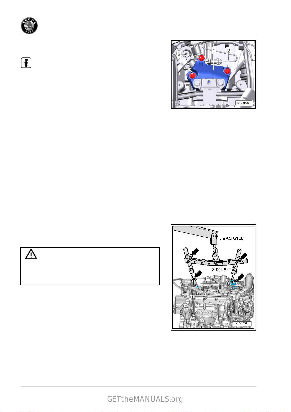
Note
The assembly bracket can be fitted with a dynamic vibration
damper -1-. This damper is an inseparable component part of the
assembly bracket - it is not removed.
Assembly bracket - gearbox
Note
Tighten screws -1- in the following sequence: rear, front and then
upwards.
1 - 50 Nm + torque a further 90° (1/4 turn) - replace
2 - 40 Nm + torque a further 90° (1/4 turn) - replace
Pendulum support
Note
Before tightening the screws -1- press off gearbox in the elonga‐
ted holes of the pendulum support to the front in such a way that
there is maximum distance between the gearbox and the assem‐
bly carrier.
A - 30 Nm + torque a further 90° (1/4 turn) - replace
B - 40 Nm + torque a further 90° (1/4 turn) - replace
2. Assembly bracket 27

Fabia II 2007 ➤ , Fabia II 2009 ➤ , Fabia II 2011 ➤ , Octavia II 2004 ➤ ...
GETtheMANUALS.org
1,2/63; 77 kW TSI engine - Edition 09.2012
2.2 Unit mounting - summary of compo‐
nents
(Octavia II, Yeti)
1 - Gearbox support bracket
2 - Screw
❑
Tightening torque ⇒
Gearbox; Rep. gr. 34
3 - Engine mounting
4 - 40 Nm + torque a further 90°
(1/4 turn)
❑ replace
5 - Bracket for activated char‐
coal filter
6 - 9 Nm
7 - 9 Nm
8 - 20 Nm + torque a further 90°
(1/4 turn)
❑ replace
9 - 20 Nm + torque a further 90°
(1/4 turn)
❑ replace
10 - Connecting part
11 - 40 Nm + torque a further
90° (1/4 turn)
❑ replace
12 - 60 Nm + torque a further
90° (1/4 turn)
❑ replace
13 - Pendulum support
❑ removing: First remove
screw -14-, then screws
-15-.
❑ installing: First tighten screws -15-, then screw -14-.
14 - 100 Nm + torque a further 90° (1/4 turn)
❑ replace
15 - Bolts
❑ replace
❑
Strength category 8.8: 40 Nm + torque a further 90° (1/4 turn)
❑
Strength category 10.9: 50 Nm + torque a further 90° (1/4 turn).
16 - 60 Nm + torque a further 90° (1/4 turn)
❑ replace
17 - 40 Nm + torque a further 90° (1/4 turn)
❑ replace
18 - Gearbox mount
28 Rep. gr.10 - Removing and installing engine

Fabia II 2007 ➤ , Fabia II 2009 ➤ , Fabia II 2011 ➤ , Octavia II 2004 ➤ ...
GETtheMANUALS.org
1,2/63; 77 kW TSI engine - Edition 09.2012
2.3 Checking and adjusting the assembly bracket
(Octavia II, Yeti)
2.3.1 Checking the assembly bracket
(Octavia II, Yeti)
– Check
• Between engine bracket and engine support there must be a
distance -a- = 10 mm.
• The cast iron edge on the engine support -2- must be parallel
to the supporting arm -1- the dimension -x- must be the same
at the front and rear.
The distance -a- can also be checked e.g. with suitable round
bars.
Only if there is an acoustic complaint (engine or gearbox knock
on the frame side rail when cornering) and the dimension -a- is
not 10 mm:
– Adjust the assembly bracket
dimensions on the right hanger for engine/gearbox unit:
Note
⇒ page 29 .
2.3.2 Adjusting the unit mounting
(Octavia II, Yeti)
Special tools and workshop equipment required
♦ Supporting device -T30099♦ Surface -T30099/1♦ Adapter -MP9-200/3 (10-222A/3)♦ Lifting eye -10-222A/12♦ Snap hook
– Remove battery and battery tray ⇒ Electrical System; Rep.
gr. 27 .
– Remove
66 .
the cooling water tank cover ⇒ Body Work; Rep. gr.
2. Assembly bracket 29

Fabia II 2007 ➤ , Fabia II 2009 ➤ , Fabia II 2011 ➤ , Octavia II 2004 ➤ ...
GETtheMANUALS.org
1,2/63; 77 kW TSI engine - Edition 09.2012
– Install
– Uniformly pre-tension the engine/gearbox assembly at both
– Release
supporting device -T30099- and support engine in fitting
position. The figure shows the version with the 1.4 ltr./90 kW
TSI Engine; the hanger is identical.
spindles, but do not raise.
the screws -2- of the assembly bracket at the engine.
– Slightly
box (less than 1 revolution).
– Successively replace all the screws of the assembly bracket
(as long as it has not already been performed when installing
the engine) and insert these loosely.
loosen the screws -2- of the unit mounting at the gear‐
30 Rep. gr.10 - Removing and installing engine

Fabia II 2007 ➤ , Fabia II 2009 ➤ , Fabia II 2011 ➤ , Octavia II 2004 ➤ ...
GETtheMANUALS.org
1,2/63; 77 kW TSI engine - Edition 09.2012
– Move the engine/gearbox assembly with an assembly lever
between the supporting arm of the engine mount
engine support -2- until the following dimensions are set:
• Between engine bracket and engine support there must be a
distance -a- of 10 mm.
• The cast iron edge on the engine support -2- must be parallel
to the supporting arm of the engine mount -1-; the dimension
-x- must be the same at the front and rear.
Note
-1- and the
The distance -a- = 10 mm can also be checked e.g. with suitable
round bars.
– Tighten the screws for the engine side assembly bracket
⇒ page 28 .
– Make
• The dimension -x- must be the same on both mount sides.
– Tighten the screws for the gearbox side assembly bracket
Further installation occurs in reverse order.
sure that on the gearbox side the edges of the support‐
ing arm of the gearbox mount -2- and the gearbox support
-1- are parallel.
⇒ page 28 .
2. Assembly bracket 31

Fabia II 2007 ➤ , Fabia II 2009 ➤ , Fabia II 2011 ➤ , Octavia II 2004 ➤ ...
GETtheMANUALS.org
1,2/63; 77 kW TSI engine - Edition 09.2012
13 – Crankshaft group
1 V-ribbed belt drive
1.1 V-ribbed belt - Summary of components
1.1.1 Summary of components - Vehicles without air conditioning
1 - V-ribbed belt
❑
Routing of the ribbed V-
⇒ page 33
belt
❑
mark the direction of ro‐
tation with chalk or a felt-
tip pen before removing
❑ check for wear
❑ do not kink
❑ removing and installing
⇒ page 35
2 - Crankshaft-belt pulley
❑
removing and installing
⇒ page 51
❑ Clamping
be free of oil and grease.
3 - Fixing screw
❑ for crankshaft - belt pul‐
ley
❑ replace
❑ The clamping surface of
the fixing screw must be
free of grease and oil.
❑ insert oiled (thread)
❑ Tightening torque;
slacken and tighten
⇒ page 51
4 - Diamond coated washer
❑ diamond
pressed onto the belt
pulley
❑ replace if damaged
5 - 20 Nm
❑ When loosening and
tightening, counterhold with the wrench for the water pump and power-assisted steering -MP 1-308
(V.A.G 1590)- to this end rework wrench for the water pump and power-assisted steering -MP 1-308
(V.A.G 1590)-
6 - Belt pulley for coolant pump
❑
removing and installing
7 - 9 Nm
8 - Vacuum hose
❑
to solenoid valve for coolant circuit -N492- at intake manifold
surfaces must
coated washer
⇒ page 123
⇒ page 123
32 Rep. gr.13 - Crankshaft group

Fabia II 2007 ➤ , Fabia II 2009 ➤ , Fabia II 2011 ➤ , Octavia II 2004 ➤ ...
GETtheMANUALS.org
1,2/63; 77 kW TSI engine - Edition 09.2012
9 - Coolant pump
❑
removing and installing
10 - 23 Nm
11 - AC generator
❑
removing and installing ⇒ Electrical System; Rep. gr. 27
❑ to facilitate the positioning of the AC generator drive the threaded bushings on the generator slightly
backwards
12 - 25 Nm
13 - Tensioning device for V-ribbed belt
❑ swivel tensioning device for V-ribbed belt with wrench to slacken the V-ribbed belt
❑ Secure the tensioning device with a 4 mm hexagon wrench or a locating pin -T10060 A-
Routing of the V-ribbed belt
1 - Belt pulley for coolant pump
2 - Tensioning pulley
3 - Belt pulley for generator
6 - Crankshaft-belt pulley
⇒ page 124
1. V-ribbed belt drive 33

Fabia II 2007 ➤ , Fabia II 2009 ➤ , Fabia II 2011 ➤ , Octavia II 2004 ➤ ...
GETtheMANUALS.org
1,2/63; 77 kW TSI engine - Edition 09.2012
1.1.2 Summary of components - Vehicles with air conditioning
1 - V-ribbed belt
❑
Routing of the ribbed V-
⇒ page 35
belt
❑
mark the direction of ro‐
tation with chalk or a felttip pen before removing
❑ check for wear
❑ do not kink
❑ removing and installing
⇒ page 35
2 - Fixing screw
❑
for crankshaft - belt pul‐
ley
❑ replace
❑ The clamping surface of
the fixing screw must be
free of grease and oil.
❑ insert oiled (thread)
❑ Tightening torque;
slacken and tighten
⇒ page 51
3 - Crankshaft-belt pulley
❑
removing and installing
⇒ page 51
❑ Clamping
be free of oil and grease.
4 - Diamond coated washer
❑ diamond coated washer
pressed onto the belt
pulley
❑ replace if damaged
5 - 20 Nm
❑ When loosening and
tightening, counterhold with the wrench for the water pump and power-assisted steering -MP 1-308
(V.A.G 1590)- to this end rework wrench for the water pump and power-assisted steering - MP 1-308
(V.A.G 1590)-
6 - Belt pulley for coolant pump
❑
removing and installing
7 - 9 Nm
8 - Vacuum hose
❑
to solenoid valve for coolant circuit -N492- at intake manifold
9 - Coolant pump
❑ removing and installing
10 - Guide pulley, 40 Nm
11 - 25 Nm
12 - Plastic cover
13 - Bracket for top auxiliary units
❑
with oil filter and engine oil cooler
❑ removing and installing
surfaces must
⇒ page 123
⇒ page 123
⇒ page 124
⇒ page 36
34 Rep. gr.13 - Crankshaft group

Fabia II 2007 ➤ , Fabia II 2009 ➤ , Fabia II 2011 ➤ , Octavia II 2004 ➤ ...
GETtheMANUALS.org
1,2/63; 77 kW TSI engine - Edition 09.2012
14 - AC generator
❑
removing and installing ⇒ Electrical System; Rep. gr. 27
❑ to facilitate the positioning of the AC generator drive the threaded bushings on the generator slightly
backwards
15 - 40 Nm + torque a further 90° (1/4 turn)
❑ replace
16 - 25 Nm
17 - AC compressor
❑ removing and installing ⇒ Heating, Air Conditioning; Rep. gr. 87
18 - 25 Nm
19 - Fitting sleeve
20 - Bracket for bottom auxiliary units
❑ for tensioning device and AC compressor
❑ removing and installing
21 - Tensioning device for V-ribbed belt
❑
swivel tensioning device for V-ribbed belt with wrench to slacken the V-ribbed belt
❑ Secure the tensioning device with a 4 mm hexagon wrench or a locating pin -T10060 A❑ to remove, release screw Pos. 12
⇒ page 38
Routing of the V-ribbed belt
1 - Belt pulley for coolant pump
2 - Guide pulley
3 - Belt pulley for generator
4 - Tensioning pulley
5 - Belt pulley for AC compressor
6 - Crankshaft-belt pulley
1.2 Removing and installing V-ribbed belt
Special tools and workshop equipment required
♦ Locking pin -T10060 ARemoving
– Remove the sound dampening system ⇒ Body Work; Rep.
gr. 50 .
Caution
Risk of damage through reversing the rotation direction of an
already used V-ribbed belt.
♦ Mark the direction of rotation with chalk or a felt-tip pen for
the re-installation before removing the V-ribbed belt.
1. V-ribbed belt drive 35

Fabia II 2007 ➤ , Fabia II 2009 ➤ , Fabia II 2011 ➤ , Octavia II 2004 ➤ ...
GETtheMANUALS.org
1,2/63; 77 kW TSI engine - Edition 09.2012
For vehicles without air conditioning
– Loosen the V-ribbed belt by swivelling the tensioning device
with a ring spanner
– Interlock the tensioning element with the locking pin -T10060
A- .
For vehicles with air conditioning
– Loosen the V-ribbed belt by swivelling the tensioning device
with a ring spanner -in direction of arrow-.
– Interlock the tensioning element with the locking pin -T10060
A- .
Continued for all vehicles
– Remove the V-ribbed belt.
Install
-in direction of arrow-.
Note
♦
Before fitting the V-ribbed belt make sure that all assemblies
(AC generator, AC compressor, coolant pump) are securely
mounted.
♦
Pay attention to the correct position and rotation direction of
the V-ribbed belt in the belt pulley when installing it.
– First of all place the ribbed V-belt onto the crankshaft - belt
pulley. Then shift the belt onto the tensioning roller.
Further installation occurs in a similar way in reverse order to re‐
moval.
– Start engine and check ribbed V-belt run.
1.3 Removing and installing bracket for top
auxiliary units
Removing
Special tools and workshop equipment required
♦ Catch pan , e.g. -VAS 6208♦ Hose binding claw
Removing
– Remove V-ribbed belt
⇒ page 35 .
– Remove alternator ⇒ Electrical System; Rep. gr. 27 .
– Drain the coolant from the cooling system ⇒ page 118 .
36 Rep. gr.13 - Crankshaft group

Fabia II 2007 ➤ , Fabia II 2009 ➤ , Fabia II 2011 ➤ , Octavia II 2004 ➤ ...
GETtheMANUALS.org
– Remove lambda probe -G39- -1-.
– Release screws -arrows- and remove heat shield -1-.
1,2/63; 77 kW TSI engine - Edition 09.2012
– Open the spring strap clamp -1- with the hose binding claw
and detach the coolant hose.
Note
When removing the oil feed line, make sure that the oil does not
penetrate into the generator! Therefore, cover the generator with
a clean cloth!
– Unscrew hollow screw -2- and fixing screw -3- and remove the
oil feed line.
– Unscrew fixing screws -1- and remove bracket.
Install
1. V-ribbed belt drive 37

Fabia II 2007 ➤ , Fabia II 2009 ➤ , Fabia II 2011 ➤ , Octavia II 2004 ➤ ...
GETtheMANUALS.org
1,2/63; 77 kW TSI engine - Edition 09.2012
– Fit the bracket for auxiliary units to the cylinder block.
– Tighten fixing screws -1- to 25 Nm.
– Install oil feed line.
Tightening torques:
Component Nm
Fixing screw to exhaust turbocharger 8 Nm
Hollow screw (replace gasket rings) 20 Nm
– Connect the coolant hose -1- and attach it to the engine oil
cooler and remove the hose clamp -MP7-602 (3094)- .
– Top up and bleed cooling system ⇒ page 118 .
– Inspect coolant level in the coolant expansion reservoir, top
up with coolant if necessary.
– Install alternator ⇒ Electrical System; Rep. gr. 27 .
– Install the V-ribbed belt ⇒ page 35 .
Further installation occurs in a similar way in reverse order to re‐
moval.
1.4 Removing
and installing bracket for bot‐
tom auxiliary units
(For vehicles with air conditioning)
Removing
– Remove V-ribbed belt
– Remove alternator ⇒ Electrical System; Rep. gr. 27 .
WARNING
Risk of injury through refrigerant.
♦ Do not open the refrigerant circuit of the air conditioning
system.
Caution
Risk of damaging refrigerant lines and hoses.
♦ Do not over-tension or buckle refrigerant lines and hoses.
– Remove AC compressor from the bracket ⇒ page 34 .
– Mount the AC compressor in such a way that the refrigerant
lines/hoses are not under tension.
⇒ page 35 .
38 Rep. gr.13 - Crankshaft group

Fabia II 2007 ➤ , Fabia II 2009 ➤ , Fabia II 2011 ➤ , Octavia II 2004 ➤ ...
GETtheMANUALS.org
1,2/63; 77 kW TSI engine - Edition 09.2012
– Unscrew fixing screws -1- and remove holder with tensioning
element.
Install
– Fit the bracket for auxiliary units to the cylinder block.
– Tighten fixing screws -1- to 25 Nm.
Tightening torque of tensioning device: ⇒ page 34
The further assembly is carried out in reverse order to disassem‐
bly.
1. V-ribbed belt drive 39

Fabia II 2007 ➤ , Fabia II 2009 ➤ , Fabia II 2011 ➤ , Octavia II 2004 ➤ ...
GETtheMANUALS.org
1,2/63; 77 kW TSI engine - Edition 09.2012
2 Camshaft drive
2.1 Camshaft drive - Summary of compo‐
nents
Note
♦
Before assembly oil all bearing and contact surfaces.
♦
If considerable quantities of metal swarf or abrasion is found
when carrying out engine repairs, this can be subject to dam‐
age to the crankshaft and conrod bearings. In order to avoid
consequential damage, after the repair perform the following
tasks:
– Carefully clean the oil galleries.
– Replace oil spray jets.
– Replace engine oil cooler.
– Replace oil filter.
1 - Cylinder head with cylinder
head cover
❑ Removing and installing
cylinder head
⇒ page 94
❑ Removing
cylinder head cover
⇒ page 84
The sealing surfaces
❑
must not be reworked
Note
2 - Cylinder block
❑
Disassembling and as‐
sembling pistons and
conrods
and installing
⇒ page 63
40 Rep. gr.13 - Crankshaft group

Fabia II 2007 ➤ , Fabia II 2009 ➤ , Fabia II 2011 ➤ , Octavia II 2004 ➤ ...
GETtheMANUALS.org
WARNING
The crankshaft must not
be removed. Merely re‐
leasing the crankshaft
bearing cover screws will
result in deformations of
the bearing seats of the
cylinder block. These de‐
formations reduce the
bearing clearance. Even
if the bearing shells were
not replaced, the
changed bearing clear‐
ance may cause dam‐
age to the bearing.
If the bearing cover
screws have been re‐
leased, replace the com‐
plete cylinder block to‐
gether with the crank‐
shaft.
It is not possible to meas‐
ure the crankshaft bear‐
ing clearance under
workshop conditions.
1,2/63; 77 kW TSI engine - Edition 09.2012
3 - Bracket for bottom auxiliary units
for tensioning device and AC compressor
❑
❑ Removing and installing
4 - 25 Nm
5 - Oil pan
removing and installing
❑
6 - 13 Nm
7 - Fixing screw
for crankshaft - belt pulley
❑
❑ replace
❑ The clamping surface of the fixing screw must be free of grease and oil.
❑ insert oiled (thread)
❑ Tightening torque; slacken and tighten
8 - Belt pulley
Pay attention to tightening process
❑
Clamping surfaces must be free of oil and grease.
❑
❑ Counterhold belt pulley with counterholder -T30004 (3415)- with bolt -T30004/2 (3415/2)- to prevent it
from turning
9 - Diamond coated washer
❑ diamond coated washer pressed onto the belt pulley
❑ replace if damaged
10 - Sealing ring
❑ replace
❑ removing and installing
⇒ page 38 for vehicles with air conditioning
⇒ page 110
⇒ page 51
⇒ page 51
⇒ page 50
2. Camshaft drive 41

Fabia II 2007 ➤ , Fabia II 2009 ➤ , Fabia II 2011 ➤ , Octavia II 2004 ➤ ...
GETtheMANUALS.org
1,2/63; 77 kW TSI engine - Edition 09.2012
11 - 50 Nm
12 - Engine support bracket
13 - 20 Nm + torque a further 90° (1/4 turn)
❑
replace
14 - Sprocket
❑ for oil pump drive
❑ Clamping surfaces must be free of oil and grease.
❑ Counterhold sprocket with counterholder -T10172-
15 - Drive chain for oil pump
❑ mark running direction (installed position) before removing
16 - Bottom cover
17 - 5 Nm + 30° further
❑ replace
❑ Screw: M6x40
18 - 5 Nm + 30° further
❑ replace
❑ Screw: M6x20
19 - Bottom timing case
❑ removing and installing
20 - Bearing bolt, 18 Nm
21 - Sliding rail
❑
for timing chain
22 - Bearing bolt, 18 Nm
⇒ page 45
23 - 50 Nm + torque a further 90° (1/4 turn)
❑ replace
24 - Tensioning rail
❑ for timing chain
25 - Screw
❑ Pay attention to tightening process
26 - Top timing case
❑
removing and installing
Caution
⇒ page 43
⇒ page 43
Pay attention to tighten‐
ing process!
27 - Timing chain
removing and installing
❑
Note
28 - Sprocket
❑ Counterhold sprocket with counterholder -T1017229 - Chain tensioner, 60 Nm
❑ for timing chain
30 - Sealing ring
⇒ page 77
42 Rep. gr.13 - Crankshaft group

Fabia II 2007 ➤ , Fabia II 2009 ➤ , Fabia II 2011 ➤ , Octavia II 2004 ➤ ...
GETtheMANUALS.org
1,2/63; 77 kW TSI engine - Edition 09.2012
2.2 Removing and installing the top timing case
Special tools and workshop equipment required
♦ Hose binding claw
♦ Sealant ⇒ Electronic catalogue of original parts(ETKA)
♦ Screw M6x70 (2x) : adapt the screws by sawing off the heads
♦ Sealant remover gasket stripper (bearing code GST, bearing
article no. R 34402), manufacturer Retech s.r.o.
♦ Cleaning and degreasing agent , e.g. -D 009 401 04♦ Protective goggles and gloves
Removing
– Drain coolant ⇒ page 118 .
– Slacken clamps -1- and -2- and detach coolant hoses.
– Unlatch
ant hoses.
– Place the coolant hoses to the rear.
the clamp -3- and pull it towards the top with the cool‐
– Unscrew fixing screws from top timing case -1-.
– Remove timing case.
Install
Installation is performed in the reverse order, pay attention to the
following points:
2. Camshaft drive 43

Fabia II 2007 ➤ , Fabia II 2009 ➤ , Fabia II 2011 ➤ , Octavia II 2004 ➤ ...
GETtheMANUALS.org
1,2/63; 77 kW TSI engine - Edition 09.2012
– To
better guide the timing case, screw two pin screws M6x70
-1- into the cylinder head cover.
WARNING
Wear protective gloves when working with sealant and grease
remover!
– Remove
timing case and at the cylinder head with chemical sealant re‐
mover.
– Degrease the sealing surfaces.
– Cut off nozzle tube at the front marking (∅ of nozzle approx.
3 mm).
♦
The installation procedure must not last longer than 6 minutes
residual sealant from the sealing surfaces on the top
Note
from the moment the sealant is applied until the moment the
fixing screws are tightened to 8 Nm.
♦
The sealant begins to harden after 6 minutes.
♦
Ensure that the tightening process of the fixing screws is car‐
ried out in two steps.
– Apply sealant on the sealing surface -1-.
– Apply a little more sealant in the area of the -arrows-.
– Position the timing case -1- onto the pin screws -2-.
Slide the timing case -1- up to the stop onto the cylinder head
cover.
Make sure that the timing case does not tilt.
– Release
Stage l of the tightening process.
the stud bolts and screw in the fixing screws by hand.
44 Rep. gr.13 - Crankshaft group

Fabia II 2007 ➤ , Fabia II 2009 ➤ , Fabia II 2011 ➤ , Octavia II 2004 ➤ ...
GETtheMANUALS.org
1,2/63; 77 kW TSI engine - Edition 09.2012
– Tighten the fixing screws to 5 Nm in the specified order -1- to
-5-.
Stage ll of the tightening process.
– Tighten the fixing screws to 8 Nm in the specified order -1- to
-7-.
– Push the clamp -3- from above fully into the bracket.
– Fit on the coolant hoses and attach the spring strap clamps
-1- and -2-.
– Top up coolant ⇒ page 118 .
2.3 Removing
and installing the bottom tim‐
ing case
Special tools and workshop equipment required
♦ Assembly device -T10417/1♦ Counterholder -T30004 (3415)♦ Bolt -T30004/2 (3415/2)♦ Sealant remover gasket stripper (bearing code GST, bearing
article no. R 34402), manufacturer Retech s.r.o.
♦ Cleaning and degreasing agent , e.g. -D 009 401 04♦ Protective goggles and gloves
♦ Sealant ⇒ Electronic catalogue of original parts(ETKA)
Removing
– Remove the sound dampening system ⇒ Body Work; Rep.
gr. 50 .
– Remove the front right wheelhouse liner ⇒ Body Work; Rep.
gr. 66 .
2. Camshaft drive 45

Fabia II 2007 ➤ , Fabia II 2009 ➤ , Fabia II 2011 ➤ , Octavia II 2004 ➤ ...
GETtheMANUALS.org
1,2/63; 77 kW TSI engine - Edition 09.2012
– Remove V-ribbed belt ⇒ page 35 .
– Remove dust cap -1-.
– Remove guide pulley -2-.
– Remove
belt pulley with the water pump wrench -V.A.G 1590- .
– Remove crankshaft-belt pulley
– Removing the oil pan ⇒ page 110 .
– Unscrew all the fixing screws from the timing case -1-.
– Carefully remove timing case.
Install
Installation is performed in the reverse order, pay attention to the
following points:
belt pulley for coolant pump, to do so counterhold the
⇒ page 51 .
WARNING
Wear protective gloves when working with sealant and grease
remover!
– Remove
tom timing case and at the cylinder block with chemical sealant
remover.
– Degrease the sealing surfaces.
– Cut off nozzle tube at the front marking (∅ of nozzle approx.
3 mm).
♦
The installation procedure must not last longer than 6 minutes
residual sealant from the sealing surfaces on the bot‐
Note
from the moment the sealant is applied until the moment the
fixing screws are tightened to 5 Nm + torqued a further 30°.
♦
The sealant begins to harden after 6 minutes.
♦
Insert new fixing screws.
– Apply sealant on the sealing surface -1-.
The sealant bead must be 2…3 mm thick and must run past
the area of the bolt holes all around the holes.
46 Rep. gr.13 - Crankshaft group

Fabia II 2007 ➤ , Fabia II 2009 ➤ , Fabia II 2011 ➤ , Octavia II 2004 ➤ ...
GETtheMANUALS.org
1,2/63; 77 kW TSI engine - Edition 09.2012
– Fit
the assembly device -T10417/1- on the crankshaft journal.
– Carefully slide the bottom timing case -1- together with the
gasket ring over the assembly device.
– Remove the assembly device from the crankshaft journal.
– Slide the bottom timing case onto the dowel pins -arrows- until
it rests against the cylinder block.
Make sure that the timing case does not tilt.
Caution
Pay attention to the tightening torque of the fixing screws!
When installing, use new screws.
– First of all tighten the new fixing screws of the timing case
evenly by hand.
– Tighten the fixing screws in the specified order -1- to -12-.
Tightening torque: 5 Nm + torque a further 30°.
Install crankshaft belt pulley ⇒ page 51 .
Tightening torques
Belt pulley for coolant pump: 20 Nm.
Guide pulley: 40 Nm.
2. Camshaft drive 47

Fabia II 2007 ➤ , Fabia II 2009 ➤ , Fabia II 2011 ➤ , Octavia II 2004 ➤ ...
GETtheMANUALS.org
1,2/63; 77 kW TSI engine - Edition 09.2012
3 Sealing flanges and flywheel
3.1 Summary of components
1 - Fixing screw
❑
for crankshaft - belt pul‐
ley
❑ replace
❑ The clamping surface of
the fixing screw must be
free of grease and oil.
❑ insert oiled (thread)
❑ Tightening torque;
slacken and tighten
⇒ page 51
2 - Belt pulley
❑
removing and installing
⇒ page 51
❑ Clamping
be free of oil and grease.
3 - Diamond coated washer
❑ diamond coated washer
pressed onto the belt
pulley
❑ replace if damaged
4 - Sealing ring
❑ replace
5 - Engine
6 - 60 Nm + torque a further 90°
(1/4 turn)
❑ replace
7 - Flywheel
❑ on vehicles with auto‐
matic gearbox - the two-
mass flywheel version
❑ removing and installing
8 - Intermediate plate
❑
must be positioned on dowel sleeves
❑ do not damage/bend during assembly work
9 - 10 Nm
❑ replace
surfaces must
⇒ page 49
10 - Sealing flange on the gearbox side
❑ Only replace sealing flange complete with gasket ring and rotor
❑ replace
11 - Engine speed sender -G28- , 5 Nm
❑
with captive screw
❑ removing and installing
12 - 5 Nm
⇒ page 55
48 Rep. gr.13 - Crankshaft group
⇒ page 260

Fabia II 2007 ➤ , Fabia II 2009 ➤ , Fabia II 2011 ➤ , Octavia II 2004 ➤ ...
GETtheMANUALS.org
1,2/63; 77 kW TSI engine - Edition 09.2012
3.2 Removing and installing flywheel
Special tools and workshop equipment required
♦ Flywheel lock -MP1-223 (3067)-
or
♦ Engine mount -MP 1-202 (VW 540)-
♦ Bushing -T30010 (VW 540/1B)-
♦ Flywheel lock -MP 1-504-
Removing
• Gearbox is removed.
– Remove
Rep. gr. 30 .
Engine installed
– Insert the counterholder -MP1-223 (3067)- into the bore hole
on the cylinder block.
• Fitting position of the counterholder:
A - for tightening
B - for slackening
clutch on vehicles with manual gearbox ⇒ Gearbox;
Engine removed
– Position the flywheel lock -MP 1-504- on the starter ring gear
of the flywheel disk and turn crankshaft until it rests against
the sleeve -T30010 - .
3. Sealing flanges and flywheel 49

Fabia II 2007 ➤ , Fabia II 2009 ➤ , Fabia II 2011 ➤ , Octavia II 2004 ➤ ...
GETtheMANUALS.org
1,2/63; 77 kW TSI engine - Edition 09.2012
Vehicles with two-mass flywheel
– Rotate
a way that the screws -B- are positioned in the middle of the
holes -arrows-.
the secondary side -A- of the two-mass flywheel in such
Caution
When unscrewing the screws -B-, ensure that no screw head
catches on the secondary side -A- of the two-mass flywheel,
otherwise the flywheel will be damaged.
Continued for all vehicles
– Release screws and remove flywheel.
Install
Installation is performed in the reverse order, pay attention to the
following points:
Note
Use new screws for attaching.
Vehicles with two-mass flywheel
– Rotate
a way that the screws -B- are positioned in the middle of the
holes -arrows-.
Continued for all
1. Screw in all the screws by hand.
2. Tighten all the screws crosswise to 60 Nm.
3.
3.3 Replacing
the secondary side -A- of the two-mass flywheel in such
Torque all the screws crosswise a further 90° (1/4 turn).
crankshaft seal on belt pulley
side
Special tools and workshop equipment required
♦ Gasket ring extractor -T30015 (3240)♦ Assembly device -T10417♦ Cap -T30003 (3161)Removing
– Remove V-ribbed belt
– Rotate
for cylinder 1
– Remove crankshaft-belt pulley ⇒ page 51 .
the crankshaft in direction of rotation of engine on TDC
⇒ page 69 .
⇒ page 35 .
50 Rep. gr.13 - Crankshaft group

Fabia II 2007 ➤ , Fabia II 2009 ➤ , Fabia II 2011 ➤ , Octavia II 2004 ➤ ...
GETtheMANUALS.org
1,2/63; 77 kW TSI engine - Edition 09.2012
– Push the adapter piece -3161- into the gasket ring extractor
-3240- .
– Unscrew the inner part of the gasket ring extractor -3240- up
to
the beginning of the thread and lock with the knurled screw.
– Oil the thread head of the gasket ring extractor, position and
apply pressure when screwing it into the gasket ring as far as
possible.
– Slacken knurled screw and turn inner side in
-direction of arrow- against the crankshaft until the gasket ring
is pulled out.
Install
– Position the sleeve -T10417/1- on the crankshaft stub and
push the gasket ring over the sleeve.
– Remove the sleeve -T10417/1- from the crankshaft stub.
– Press the gasket ring with the assembly device -T10417- by
striking uniformly up to the stop in the timing case.
Install crankshaft belt pulley ⇒ page 51 .
Further installation occurs in a similar way in reverse order to re‐
moval.
3.4 Removing and installing crankshaft-belt
pulley
Special tools and workshop equipment required
♦ Counterholder -T30004 (3415)♦ Bolt -T30004/2 (3415/2)♦ Fixing screw -T10340-
3. Sealing flanges and flywheel 51
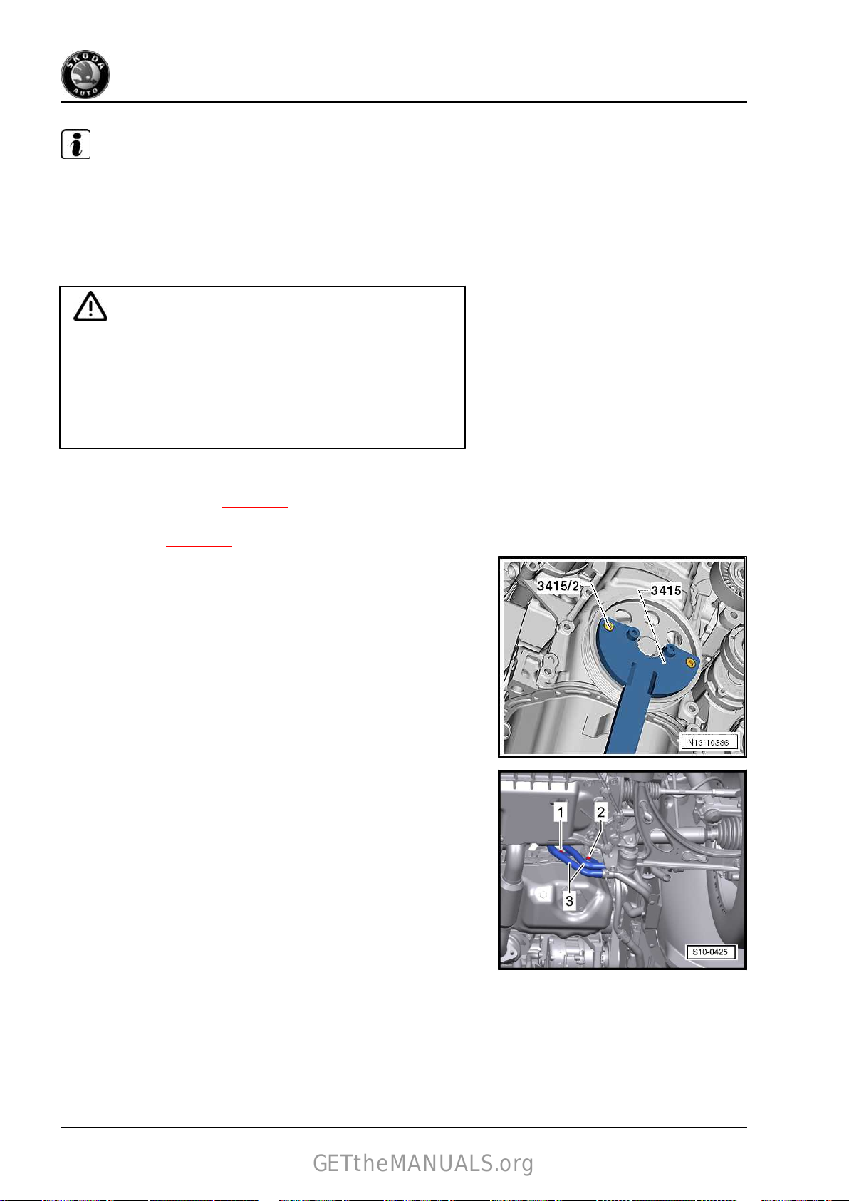
Fabia II 2007 ➤ , Fabia II 2009 ➤ , Fabia II 2011 ➤ , Octavia II 2004 ➤ ...
GETtheMANUALS.org
1,2/63; 77 kW TSI engine - Edition 09.2012
Note
♦
In order to avoid that the tightening torque of the fixing screw
for the crankshaft-belt pulley is inaccurate due to slip, the fixing
screw -T10340- must be used in addition to the counterholder
-T30004- .
♦
The crankshaft is only locked in direction of rotation of engine
using the fixing screw -T10340- .
Caution
Risk of engine damage!
♦ The fixing screw -T10340- must not be used to slacken the
fixing screw for the crankshaft-belt pulley - only for tight‐
ening!
♦ The locating screw -T10340- must only be screwed in the
“TDC” position of the crankshaft.
Removing
– Remove V-ribbed belt ⇒ page 35 .
– Rotate
for cylinder 1
– Counterhold belt pulley with counterholder -T30004 (3415)-
with
pulley.
– Remove the belt pulley together with the diamond coated
washer.
Install
Vehicles with auxiliary heating.
the crankshaft in direction of rotation of engine on TDC
⇒ page 69 .
bolt -T30004/2 (3415/2)- and release fixing screw for belt
– Screw
pipes for the auxiliary heating -3-.
Continued for all vehicles
out the screws -1 and 2- of the brackets for the coolant
52 Rep. gr.13 - Crankshaft group

Fabia II 2007 ➤ , Fabia II 2009 ➤ , Fabia II 2011 ➤ , Octavia II 2004 ➤ ...
GETtheMANUALS.org
1,2/63; 77 kW TSI engine - Edition 09.2012
– Release
-2-.
♦
Make sure that all clamping surfaces of the fixing screw are
fixing screws -1- and remove bracket for coolant pipe
Note
free of oil and grease up to the crankshaft chain sprocket.
♦
Always use a new screw of the crankshaft belt pulley.
– Install the belt pulley together with the diamond coated washer
and tighten the new fixing screw by hand.
– Release screw plug -arrow- at cylinder block.
Note
♦
Using the fixing screw should prevent the crankshaft from
turning when tightening to the tightening torque.
♦
As a result the tightening torque may not be correct.
– Turn the fixing screw -T10340- up to the stop in the cylinder
block.
Caution
If the fixing screw -T10340 - cannot be screwed in up to the
stop, the crankshaft is not in the correct position!
In this case, proceed as follows.
– Unscrew the fixing screw.
–
– Turn the fixing screw -T10340- up to the stop in the cylinder
– Tighten fixing screw -T10340- to 30 Nm.
– Turn crankshaft up to the stop in direction of rotation of engine.
The crankshaft is locked in direction of rotation of engine with the
fixing screw -T10340- .
crankshaft 90° (1/4 turn) in direction of rotation of engine.
Turn
block.
Caution
Absolutely use the counterholder -T30004 (3415)- with bolt T30004/2 (3415/2)- when tightening the fixing screw of the belt
pulley in order to avoid damage to the fixing screw.
3. Sealing flanges and flywheel 53

Fabia II 2007 ➤ , Fabia II 2009 ➤ , Fabia II 2011 ➤ , Octavia II 2004 ➤ ...
GETtheMANUALS.org
1,2/63; 77 kW TSI engine - Edition 09.2012
– Insert counterholder -3415- with the bolt -3415/1- into the
holes of the crankshaft belt pulley, support counterholder at
track control arm -A- and secure in this position with a cable
strap. Tighten cable strap.
– Tighten fixing screw of crankshaft-belt pulley in two stages:
Stage 1: Tightening torque: 150 Nm
– Mark at this stage the position of the fixing screw -3- to the
crankshaft belt pulley -1-
performed on the washer -2-, because the washer does not
turn along when tightening.
– Tighten fixing screw of crankshaft belt pulley to the 2nd step
as follows:
-arrows-. The marking must not be
Stage 2: Torque screw a further 180° (1/2 turn).
Tightening may occur in successive stages.
– Release the fixing screw -T10340- from the cylinder block.
– Screw
the screw plug again into the cylinder block. Tightening
torque: 30 Nm.
54 Rep. gr.13 - Crankshaft group

Fabia II 2007 ➤ , Fabia II 2009 ➤ , Fabia II 2011 ➤ , Octavia II 2004 ➤ ...
GETtheMANUALS.org
1,2/63; 77 kW TSI engine - Edition 09.2012
– Install bracket for coolant pipe -2- and tighten screws -1-.
Tightening torque
Screw M6 = 10 Nm
Screw M8 = 20 Nm
– Install the V-ribbed belt ⇒ page 35 .
Further installation occurs in a similar way in reverse order to re‐
moval.
3.5 Replace sealing flange on the gearbox side
Special tools and workshop equipment required
♦ Assembly tool -T10134♦ Feeler gauges
♦ Steel straightedge
♦ Screw M6x35 (3x)
♦ Screw M7x35 (2x)
3.5.1 Removing
Precondition
• Gearbox is removed.
– Remove flywheel and take off intermediate plate.
– Position engine on TDC for cylinder 1 ⇒ page 69 (do not
remove the screw cap for the camshafts).
– Removing the oil pan ⇒ page 110 .
– Remove engine speed sender -G28- -arrow-.
– Unscrew the fixing screws of the sealing flange.
Note
Sealing flange and rotor are pressed together with three M6 x 35
mm screws from the crankshaft.
– Screw three screws M6x35 into the threaded bores of the
sealing flange
–
Screw the screws alternately (max 1/2 turn (180°) per screw)
in the sealing flange and press the sealing flange together with
the rotor from the crankshaft.
-arrows-.
3. Sealing flanges and flywheel 55

Fabia II 2007 ➤ , Fabia II 2009 ➤ , Fabia II 2011 ➤ , Octavia II 2004 ➤ ...
GETtheMANUALS.org
1,2/63; 77 kW TSI engine - Edition 09.2012
3.5.2 Install
Note
♦
The sealing flange with PTFE gasket ring is provided with
sealing lip supporting ring. This supporting ring is intended as
an assembly sleeve and must not be removed before instal‐
ling.
♦
Do not separate or turn the sealing flange and rotor after re‐
moving them from the spare part package.
♦
The rotor is given its fitting location by fixing the assembly tool
-T10134- to the positioning pin.
♦
The sealing flange and gasket ring form one unit and must be
replaced together with the rotor.
♦
The assembly tool -T10134- is given its fitting location to the
crankshaft by means of a guide bolt, which is guided into a
hole of the crankshaft.
Assembly tool -T10134A - Hexagon nut
B - Clamping surface
C - Assembly cup
D - Allan screw
E - Guide bolts (with red handle - for fuel engine)
F - Positioning pin
G - Guide bolts (with black handle - for diesel engine)
A - Mounting sealing flange with rotor on the assembly tool -
T10134-
– Screw the hexagon nut -A- right up to the clamping surface
-B- and grip the assembly tool -T10134- on the clamping sur‐
face -B- of the threaded spindle in a vice.
– Remove
Do not remove or turn the rotor from the sealing flange.
the securing clip -arrow- from the new sealing flange.
Note
56 Rep. gr.13 - Crankshaft group

Fabia II 2007 ➤ , Fabia II 2009 ➤ , Fabia II 2011 ➤ , Octavia II 2004 ➤ ...
GETtheMANUALS.org
1,2/63; 77 kW TSI engine - Edition 09.2012
– Lay the front side of the sealing flange on a clean and level
surface.
– Press down sealing lips supporting ring -A- in
-direction of the arrow-, until it rests on the level surface.
Note
The top edge of the rotor and the front edge of the sealing flange
must be flush.
• The locating hole -B- on the rotor -C- must be flush with the
marking -A- on the sealing flange.
– Lay
the sealing flange with the front side on the assembly tool
-T10134- in such a way that the positioning pin -A- engages
into the hole -B- of the rotor.
Note
Make sure the sealing flange lies flat on the assembly tool.
– When tightening the knurled screws -A- press the sealing lip
supporting
a way that the positioning pin cannot slide out of the rotor hole.
B - Mount the assembly tool -T10134- on the crankshaft flange
• The crankshaft flange must be free of grease and oil
• Crankshaft is at TDC for cylinder 1
– Unscrew hexagon nut up to the end of the threaded spindle.
ring -B- on the surface of the assembly tool in such
3. Sealing flanges and flywheel 57

Fabia II 2007 ➤ , Fabia II 2009 ➤ , Fabia II 2011 ➤ , Octavia II 2004 ➤ ...
GETtheMANUALS.org
1,2/63; 77 kW TSI engine - Edition 09.2012
– Screw
stop onto the crankshaft flange.
– Screw
ing flange guide into the cylinder block.
assembly tool -T10134- with Allan screws -A- up to the
in two M6x35 mm screws -A- by about 3 turns for seal‐
– Move the assembly cup -C- by hand in the
-direction of the arrow- until the rotor shaft flange -A-. Subsequently insert the guide bolt with red
ball -F- fully into the threaded bore of the crankshaft. If the
guide bolt is correctly pushed in, then the handle has a dis‐
tance of approx. 10 mm from the assembly cup -C-. This gives
the rotor its final fitting location.
C - Pressing the rotor onto the crankshaft flange
– Screw in hexagon nut by hand onto the threaded spindle until
it rests against the assembly cup.
– Tighten the hexagon nut of the assembly tool using a torque
wrench with adapter.
Tightening torque: 35 Nm.
Note
B- rests on the crank‐
After tightening the nut to 35 mm there must still be a narrow air
gap between the cylinder block and the sealing flange.
D - Inspecting the fitting position of the rotor on the crankshaft
58 Rep. gr.13 - Crankshaft group

Fabia II 2007 ➤ , Fabia II 2009 ➤ , Fabia II 2011 ➤ , Octavia II 2004 ➤ ...
GETtheMANUALS.org
1,2/63; 77 kW TSI engine - Edition 09.2012
– Unscrew hexagon nut -E- up to the end of the threaded spin‐
dle.
– Unscrew two M6x35 mm screws -A- from the cylinder block.
– Release three knurled screws -B- from the sealing flange.
– Unscrew two Allan screws and remove assembly tool -
T10134- .
– Remove sealing lip supporting ring.
The fitting position of the rotor on the crankshaft is accurate if
there is a distance -a- = 0.5 mm between the crankshaft flange
-A- and the rotor -B-.
– Position the steel striaghtedge onto the crankshaft flange.
– Measure
rotor with a feeler gauge.
If the measured distance is less than 0.5 mm:
– Press down rotor
If the dimension is correct:
– Tighten
wise.
Tightening torque: 10 Nm.
– Install engine speed sender -arrow-.
Tightening torque: 5 Nm.
– Installing the oil pan ⇒ page 110 .
– Installing intermediate plate.
– Install flywheel with new screws.
E - Pressing down the rotor
the distance between the steel straightedge and the
⇒ page 59 .
the new fixing screws of the sealing alternately cross‐
3. Sealing flanges and flywheel 59

Fabia II 2007 ➤ , Fabia II 2009 ➤ , Fabia II 2011 ➤ , Octavia II 2004 ➤ ...
GETtheMANUALS.org
1,2/63; 77 kW TSI engine - Edition 09.2012
– Screw
– Screw in three knurled screws -A- into the flange.
– Subsequently insert the guide bolt with red ball -E- fully into
– Tighten the hexagon nut of the assembly tool using a torque
– Inspect
If the dimension -a- is too small again:
– Tighten the hexagon nut of the assembly tool to 45 Nm.
– Inspect
assembly tool -T10134- with Allan screws up to the stop
onto the crankshaft flange.
the threaded bore of the crankshaft. If the guide bolt is correctly
slipped on, then the handle has a distance of approx. 10 mm
from the assembly cup -B-.
wrench with adapter.
Tightening torque: 40 Nm.
the fitting position of the rotor on the crankshaft again
⇒ page 58 .
the fitting position of the rotor on the crankshaft again
⇒ page 58 .
60 Rep. gr.13 - Crankshaft group
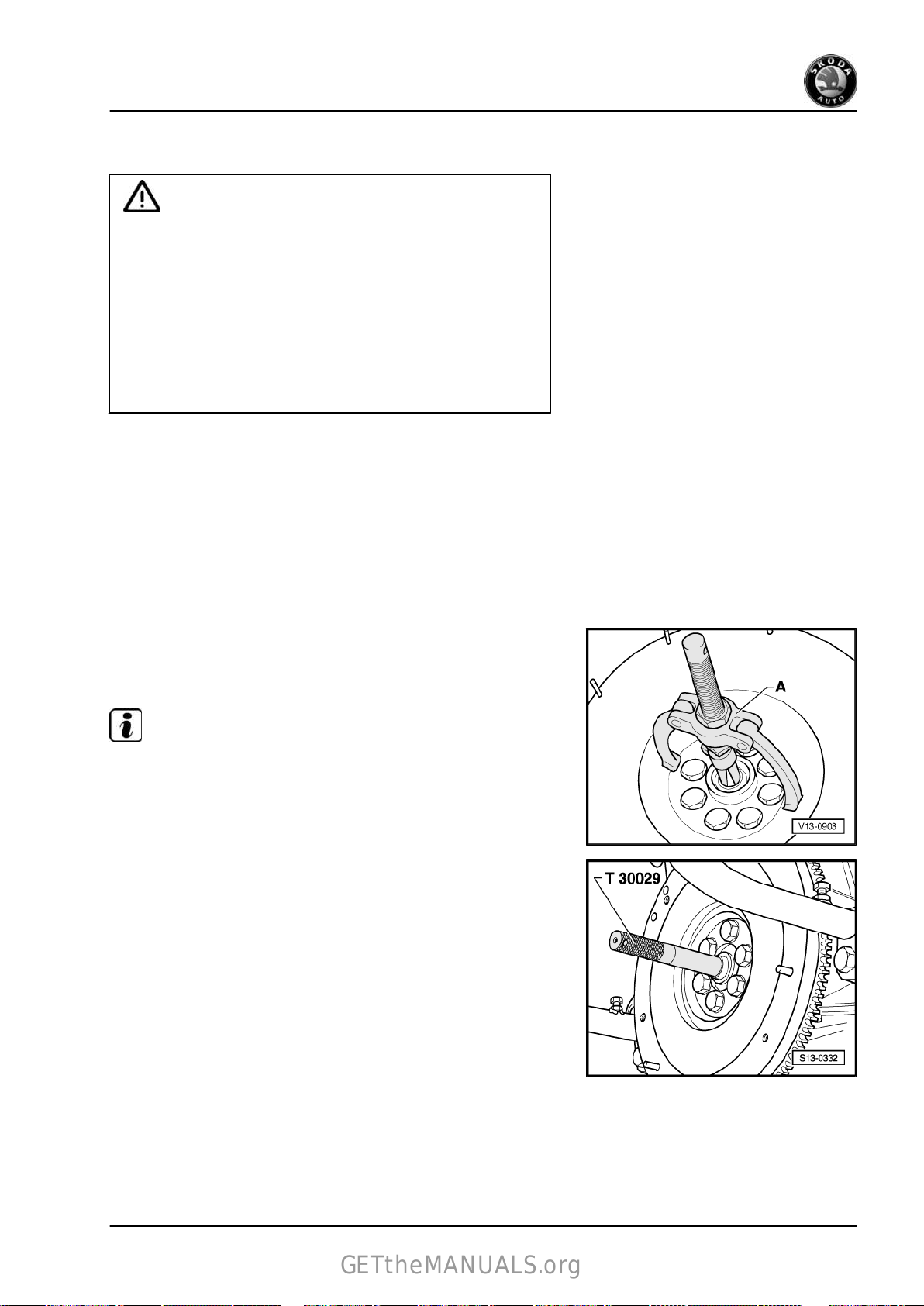
Fabia II 2007 ➤ , Fabia II 2009 ➤ , Fabia II 2011 ➤ , Octavia II 2004 ➤ ...
GETtheMANUALS.org
1,2/63; 77 kW TSI engine - Edition 09.2012
4 Crankshaft
Caution
The crankshaft must not be removed. Merely releasing the
screws of the crankshaft bearing cover will result in deforma‐
tions of the bearing seats of the cylinder block. These defor‐
mations will cause a reduction of the bearing clearance. If the
bearing shells are not replaced, the changed bearing clear‐
ance may cause damage to the bearing.
If the bearing cover screws have been released, replace the
complete cylinder block together with the crankshaft.
It is not possible to measure the crankshaft bearing clearance
with workshop tools.
4.1 Replace needle bearing for crankshaft
Only on vehicles equipped with automatic gearbox.
Special tools and workshop equipment required
♦ Centering mandrel -T30029 (3176)♦ Interior extractor -Kukko 21/2♦ Countersupport - Kukko 22/1Removing
– Pull
Install
out needle bearing with interior extractor -Kukko 21/2- and
countersupport -Kukko 22/1- .
Note
The marked side of the needle bearing should be legible when in
its installed condition.
– Drive
• Fitting position: The marked side of the needle bearing should
in the needle bearing using the centering pin -T30029- .
be legible when in its installed condition.
4. Crankshaft 61

Fabia II 2007 ➤ , Fabia II 2009 ➤ , Fabia II 2011 ➤ , Octavia II 2004 ➤ ...
GETtheMANUALS.org
1,2/63; 77 kW TSI engine - Edition 09.2012
Depth of installation of the needle bearing
• Dimension -a-: 1.5 up to 1.8 mm
62 Rep. gr.13 - Crankshaft group

Fabia II 2007 ➤ , Fabia II 2009 ➤ , Fabia II 2011 ➤ , Octavia II 2004 ➤ ...
GETtheMANUALS.org
5 Pistons and conrods
5.1 Summary of components
Note
Before assembly oil all bearing and contact surfaces.
1 - Circlip
2 - Piston pin
❑ if stiff, heat piston to 60°
C
❑ use drift -T10046- for re‐
moving and installing
3 - Piston
❑ check
❑
❑ arrow on the piston
❑ use piston ring tension‐
❑ Piston ∅: 70,95 mm
❑ Cylinder ∅: 71.00 mm
4 - Piston rings
❑ Offset joint 120°
❑ Use piston ring pliers for
❑ Marking “TOP” faces
❑ Inspect gap clearance
❑
5 - Oil scraper rings
❑ carefully
❑ Inspect gap clearance
❑
⇒ page 65
mark installation posi‐
tion and matching cylin‐
der
crown faces towards the
belt pulley side
ing strap for installing
(nominal dimension)
(nominal dimension)
removing and installing
compression rings
piston crown
⇒ page 64
Inspect end clearance
⇒ page 64
remove and in‐
stall 3-part oil scraper rings by hand
⇒ page 64
End clearance cannot be measured
1,2/63; 77 kW TSI engine - Edition 09.2012
6 - 30 Nm + torque a further 90° (1/4 turn)
❑ replace
❑ Oil thread and contact surface
7 - Conrod bearing cap
❑ as a result of the conrods separated in the cracking process, the cover fits only in one position and only
to the relevant conrod
❑ Mark the assignment of the cylinder before removal -A-
5. Pistons and conrods 63

Fabia II 2007 ➤ , Fabia II 2009 ➤ , Fabia II 2011 ➤ , Octavia II 2004 ➤ ...
GETtheMANUALS.org
1,2/63; 77 kW TSI engine - Edition 09.2012
❑ Fitting position: Marking -B- points to the belt pulley side (mark before removing if marking is missing)
8 - Bearing shell
❑
do not mix up used bearing shells
❑ insert bearing shells in the centre
9 - Pressure relief valve, 27 Nm
❑ Opening pressure: 0,2 MPa (2,0 bar)
10 - Oil injection nozzle
❑ for piston cooling
❑ Align the guide edge of the oil injection nozzle -arrow- to the area of the cylinder block being worked on.
11 - Conrod
❑ always replace as a set only
❑ mark matching cylinder -A❑ Fitting position: Marking -B- points to the belt pulley side (mark before removing if marking is missing)
❑ located axially by pistons
❑ separate new conrod
⇒ page 66
5.2 Inspect piston, piston rings and cylinder bore
Inspecting piston ring gap clearance
Special tools and workshop equipment required
♦ Feeler gauges
– Insert
Piston ring
dimensions in mm
1. Compression ring 0,20…0,40 1,0
2. Compression ring 0,40…0,60 1,0
Oil scraper ring 0,25…0,75 no wear indication
Inspect piston ring end clearance
ring at right angles from above down into lower cylinder
opening, about 15 mm away from edge of cylinder.
New Wear limit
possible
Special tools and workshop equipment required
64 Rep. gr.13 - Crankshaft group

Fabia II 2007 ➤ , Fabia II 2009 ➤ , Fabia II 2011 ➤ , Octavia II 2004 ➤ ...
GETtheMANUALS.org
♦ Feeler gauges
– Clean ring groove before inspecting.
1,2/63; 77 kW TSI engine - Edition 09.2012
Piston ring
dimensions in mm
1. Compression ring 0,03…0,09 0,15
2. Compression ring 0,02…0,06 0,15
Oil scraper ring cannot be measured
Inspecting pistons
Special tools and workshop equipment required
♦ External micrometer 75...100 mm
– Measure about 7 mm from the lower edge and offset 90° to
piston pin axis.
• Deviations from specified dimension: max. 0,04 mm
Inspecting cylinder bore
New Wear limit
Special tools and workshop equipment required
♦ Internal precision measuring instrument 50...100 mm
– Measure
lengthwise -B-.
• Deviations from specified dimension: max. 0,08 mm
at 3 points crosswise in a transverse direction -A- and
5. Pistons and conrods 65
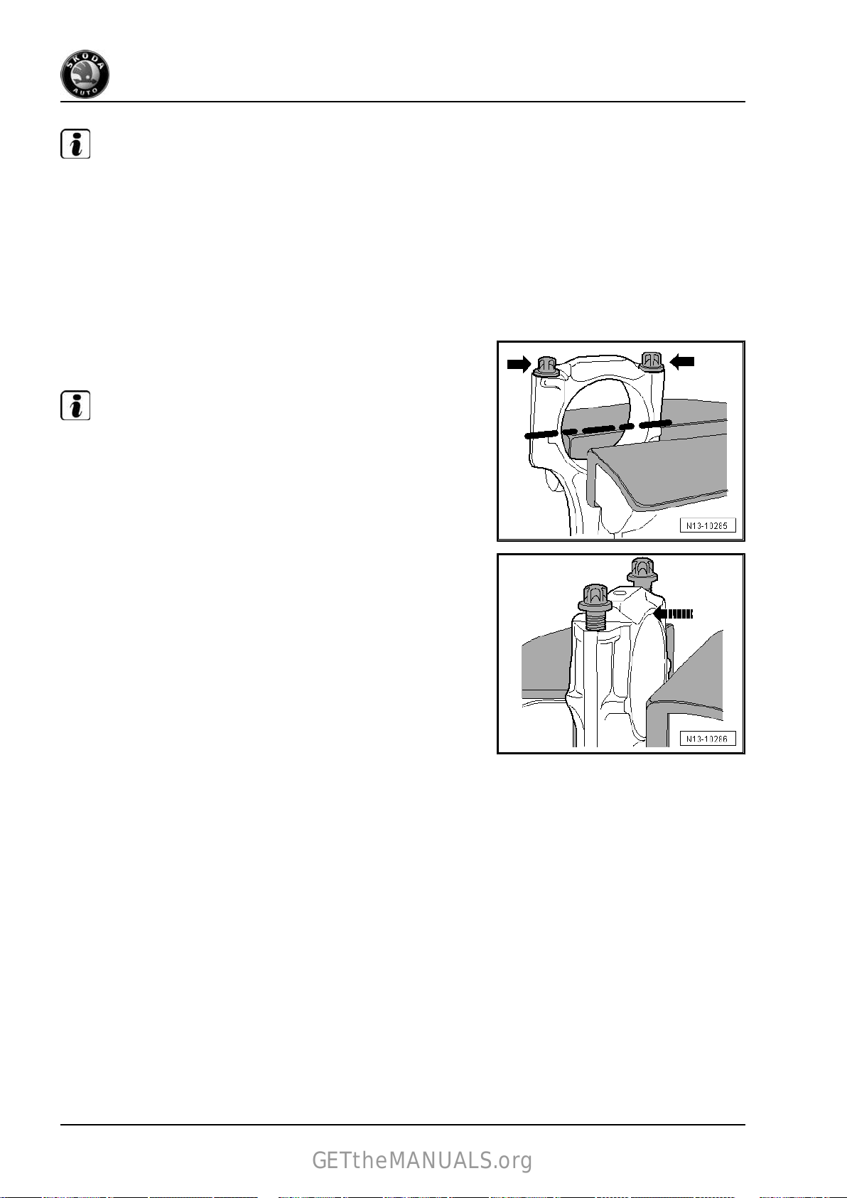
Fabia II 2007 ➤ , Fabia II 2009 ➤ , Fabia II 2011 ➤ , Octavia II 2004 ➤ ...
GETtheMANUALS.org
1,2/63; 77 kW TSI engine - Edition 09.2012
Note
Do not measure the cylinder bore if the cylinder block is fixed to
the assembly stand -MP 1-202- with the engine mount -MP 9-101
- , as this may result in incorrect measurements.
5.3 Separating new conrod
It can happen that the predetermined breaking point on the new
conrod
be removed by hand, then proceed as follows:
– Mark the assignment of the conrod to the cylinder.
– Slightly clamp the conrod in a vice provided with aluminium
♦
♦
is not completely pierced. If the conrod bearing cap cannot
protective jaws, as shown in the illustration.
Note
Only tension the conrod slightly in order to avoid damage on
the conrod.
The conrod is clamped below the broken line.
– Unscrew both screws -arrows- by approx. 5 turns.
– Carefully knock against the conrod bearing cap with a rubber
hammer in -direction of arrow-
in order to loosen it.
66 Rep. gr.13 - Crankshaft group

Fabia II 2007 ➤ , Fabia II 2009 ➤ , Fabia II 2011 ➤ , Octavia II 2004 ➤ ...
GETtheMANUALS.org
1,2/63; 77 kW TSI engine - Edition 09.2012
15 – Cylinder head, valve gear
1 Cylinder head - part 1
1.1 Summary of components
Testing compression pressure ⇒ page 100 .
Note
♦
When installing a replacement cylinder head, all the contact
surfaces between the hydraulic balancing elements, the cam
followers and the cam tracks must be oiled before installing
the cylinder head cover.
♦
Do not remove the plastic bases supplied as a protection for
the open valves until just before fitting on the cylinder head.
♦
If the cylinder head is replaced, also the entire coolant must
be replaced.
♦
Before assembly moisten all bearing and contact surfaces with
oil.
♦
Removing and installing intake manifold ⇒ page 223 .
1. Cylinder head - part 1 67

Fabia II 2007 ➤ , Fabia II 2009 ➤ , Fabia II 2011 ➤ , Octavia II 2004 ➤ ...
GETtheMANUALS.org
1,2/63; 77 kW TSI engine - Edition 09.2012
1 - 20 Nm
2 - High pressure pump
❑
for fuel supply
❑ with fuel pressure regu‐
lating valve -N276-
❑ removing and installing
⇒ page 229
3 - 10 Nm
4 - Hall sender -G40-
❑
with O-ring
❑ replace the O-ring if it is
damaged
5 - 20 Nm
6 - Lifting eye
7 - 8 Nm + torque a further 90°
(1/4 turn)
❑ replace
❑ order of tightening
⇒ page 84
8 - Cylinder head cover
❑
removing and installing
⇒ page 84
Note
9 - 10 Nm
10 - Coolant temperature
sender -G62-
before removing, re‐
❑
duce pressure in cooling
system
11 - O-ring
❑ replace
12 - Cylinder head gasket
❑ replace
❑ metal gasket
❑ after replacing fill entire system with fresh coolant
13 - Cylinder head
❑ removing and installing:
♦ Fabia II, Roomster, Rapid NH
♦
Octavia II, Yeti
❑
check for distortion
❑
Sealing surfaces must be free of oil and grease
❑ after replacing fill entire system with fresh coolant
14 - Hydraulic balancing element
❑ do not interchange
❑ with hydraulic valve clearance compensation
❑ oil contact surfaces
⇒ page 98
⇒ page 69
⇒ page 94
68 Rep. gr.15 - Cylinder head, valve gear

Fabia II 2007 ➤ , Fabia II 2009 ➤ , Fabia II 2011 ➤ , Octavia II 2004 ➤ ...
GETtheMANUALS.org
1,2/63; 77 kW TSI engine - Edition 09.2012
15 - Oil pressure switch -F1- , 20 Nm
❑
❑
16 - Roller rocker arm
❑ inspect roller bearings for smooth operation
❑ oil contact surfaces
❑ for installing, clip onto the balancing element with the locking clip
17 - Cylinder head bolt
❑ replace
❑ observe the mounting instructions and sequence for loosening and tightening
18 - Roller tappet
❑
19 - O-ring
❑ replace
❑ moisten with oil before inserting
Inspecting the cylinder head for distortion
Check with straightedge 500 mm , e. g. -VAS 6075- and feeler
gauge.
• Max. permissible distortion: 0.05 mm
⇒ page 114
check
Cut open gasket ring if leaking and replace
Lightly moisten the contact surface with engine oil
⇒ page 94
1.2 Test timing
Special tools and workshop equipment required
♦ Fixing bolts -T10414♦ Fixing screw -T10340Test sequence
Vehicles with auxiliary heating.
– Unscrew the screws -1 and 2- of the brackets for the coolant
pipes for the auxiliary heating -3-.
Continued for all vehicles
1. Cylinder head - part 1 69

Fabia II 2007 ➤ , Fabia II 2009 ➤ , Fabia II 2011 ➤ , Octavia II 2004 ➤ ...
GETtheMANUALS.org
1,2/63; 77 kW TSI engine - Edition 09.2012
– Release
-2-.
– Release screw plug -arrow- at cylinder block.
fixing screws -1- and remove bracket for coolant pipe
– Turn the fixing screw -T10340- up to the stop in the cylinder
block.
Caution
If the fixing screw -T10340 - cannot be screwed in up to the
stop, the crankshaft is not in the correct position!
In this case, proceed as follows.
– Unscrew the fixing screw.
–
– Turn the fixing screw -T10340- up to the stop in the cylinder
– Tighten fixing screw -T10340- to 30 Nm.
– Turn crankshaft up to the stop in direction of rotation of engine.
The crankshaft is locked in direction of rotation of engine with the
fixing screw -T10340- .
– Separate the hoses -1- from the non-return valve.
– Release the fixing screw -2- and pull the non-return valve out
crankshaft 90° (1/4 turn) in direction of rotation of engine.
Turn
block.
of the cylinder head cover.
70 Rep. gr.15 - Cylinder head, valve gear

Fabia II 2007 ➤ , Fabia II 2009 ➤ , Fabia II 2011 ➤ , Octavia II 2004 ➤ ...
GETtheMANUALS.org
1,2/63; 77 kW TSI engine - Edition 09.2012
The grooves in the camshaft -arrows- must be in the position
shown.
– Insert the fixing bolt -T10414- up to the stop into the cylinder
head cover.
– Tighten fixing screw -1- by hand.
If the fixing bolt -T10414- cannot be inserted up to the stop into
the camshaft opening, the timing is not correct and must be set
⇒ page 71 .
The timing is O.K., if the fixing bolt -T10414- can be pushed up to
the stop into the cylinder head cover.
– Remove fixing bolt -T10414- and fixing screw -T10340- .
Further installation occurs in a similar way in reverse order to re‐
moval.
1.3 Setting the timing
Special tools and workshop equipment required
♦ Fixing bolts -T10414♦ Fixing screw -T10340♦ Counterholder -T10172 Work procedure
– Drain coolant
– Remove top timing case ⇒ page 43 .
– Separate the hoses -1- from the non-return valve.
– Release the fixing screw -2- and pull the non-return valve out
of the cylinder head cover.
Vehicles with auxiliary heating.
⇒ page 118 .
1. Cylinder head - part 1 71

Fabia II 2007 ➤ , Fabia II 2009 ➤ , Fabia II 2011 ➤ , Octavia II 2004 ➤ ...
GETtheMANUALS.org
1,2/63; 77 kW TSI engine - Edition 09.2012
– Unscrew the screws -1 and 2- of the brackets for the coolant
pipes for the auxiliary heating
Continued for all vehicles
-3-.
– Release
-2-.
– Release screw plug -arrow- at cylinder block.
fixing screws -1- and remove bracket for coolant pipe
72 Rep. gr.15 - Cylinder head, valve gear

Fabia II 2007 ➤ , Fabia II 2009 ➤ , Fabia II 2011 ➤ , Octavia II 2004 ➤ ...
GETtheMANUALS.org
1,2/63; 77 kW TSI engine - Edition 09.2012
– Turn the fixing screw -T10340- up to the stop in the cylinder
block.
Caution
If the fixing screw -T10340 - cannot be screwed in up to the
stop, the crankshaft is not in the correct position!
In this case, proceed as follows.
– Unscrew the fixing screw.
–
Turn
crankshaft 90° (1/4 turn) in direction of rotation of engine.
– Turn the fixing screw -T10340- up to the stop in the cylinder
block.
– Tighten fixing screw -T10340- to 30 Nm.
– Turn crankshaft up to the stop in direction of rotation of engine.
The crankshaft is locked in direction of rotation of engine with the
fixing screw -T10340- .
For vehicles manufactured up to 12.2009
Note
On these vehicles, the timing chain can slip off the crankshaft gear
when installing.
– Removing the oil pan
– Pull off the cover -1- from the oil pump.
Continued for all vehicles
– Release chain tensioner -arrow- for timing chain.
⇒ page 110 .
1. Cylinder head - part 1 73

Fabia II 2007 ➤ , Fabia II 2009 ➤ , Fabia II 2011 ➤ , Octavia II 2004 ➤ ...
GETtheMANUALS.org
1,2/63; 77 kW TSI engine - Edition 09.2012
– Hold the camshaft sprocket with the counterholder -T10172-
and slacken the fixing screw
– Remove the camshaft sprocket together with the fixing screw.
– Place the chain sprocket -1- down on the integrated peg
-arrow- in the timing case.
Note
The integrated peg on the inner side of the timing case prevents
the chain sprocket from falling down.
-1- of the camshaft sprocket.
– Position
the fixing screw -2- to 50 Nm.
– Hold the camshaft sprocket with the counterholder -T10172-
when tightening.
–
Then turn back the crankshaft 90° (1/4 turn) in the opposite
direction of rotation of the engine.
When subsequently adjusting the camshaft, damage to the valves
is prevented by turning the crankshaft in the opposite direction of
rotation of the engine.
– Turn
shown.
the camshaft sprocket -1- on the camshaft and tighten
Note
the camshaft until the grooves -arrows- are in the position
74 Rep. gr.15 - Cylinder head, valve gear

Fabia II 2007 ➤ , Fabia II 2009 ➤ , Fabia II 2011 ➤ , Octavia II 2004 ➤ ...
GETtheMANUALS.org
1,2/63; 77 kW TSI engine - Edition 09.2012
– Insert the fixing bolt -T10414- up to the stop into the cylinder
head cover.
– Tighten fixing screw -1- by hand.
– Turn
– Lift up the timing chain with the assembly device -T10118- .
For vehicles manufactured up to 12.2009
crankshaft up to the stop in direction of rotation of engine.
Note
On these vehicles, the timing chain can slip off the crankshaft gear
when installing.
– Check
shaft gear from below.
Continued for all vehicles
– Place the timing chain -1- onto the chain sprocket -2-.
♦
The timing chain must rest in the area of the sliding rail -3- and
the correct position of the timing chain -1- on the crank‐
Note
be slightly tensioned.
♦
The timing chain must run through the middle of the sliding rail.
– Install fixing screw for camshaft sprocket and tighten by hand.
1. Cylinder head - part 1 75

Fabia II 2007 ➤ , Fabia II 2009 ➤ , Fabia II 2011 ➤ , Octavia II 2004 ➤ ...
GETtheMANUALS.org
1,2/63; 77 kW TSI engine - Edition 09.2012
– Install chain tensioner and tighten to 60 Nm.
– Hold the camshaft sprocket with the counterholder -T10172-
and tighten the fixing screw -1- of the camshaft sprocket to 50
Nm.
Note
The fixing screw is only turned a further 90° (1/4 turn) after check‐
ing the timing at the end of the work procedure.
– Remove the fixing bolt -T10414 - from the camshaft.
– Release the fixing screw -T10340- from the cylinder block.
– Turn the crankshaft in direction of rotation of engine by 2 turns.
– Turn the fixing screw -T10340- up to the stop in the cylinder
block.
– Turn crankshaft up to the stop in direction of rotation of engine.
The timing is O.K., if the fixing bolt -T10414- can be inserted in
the camshaft.
If the timing is not O.K., the setting of the timing must be repeated.
If timing is o.k.:
– Hold the camshaft sprocket with the counterholder -T10172-
and torque the fixing screw
– Remove fixing bolt -T10414- and fixing screw -T10340- .
– Install top timing case
-1- a further 90° (1/4 turn).
⇒ page 43 .
76 Rep. gr.15 - Cylinder head, valve gear

Fabia II 2007 ➤ , Fabia II 2009 ➤ , Fabia II 2011 ➤ , Octavia II 2004 ➤ ...
GETtheMANUALS.org
1,2/63; 77 kW TSI engine - Edition 09.2012
– Install non-return valve. Tightening torque of the fixing screw
-2-: 8 Nm.
– Fit on hoses -1-.
For vehicles manufactured as of 12.2009
– Installing the oil pan ⇒ page 110 .
Continued for all vehicles
– Install screw plug. Tightening torque: 30 Nm
– Top up coolant ⇒ page 118 .
For vehicles manufactured as of 06.2011
– Erase the initialisation values and adapt the engine control unit
-J623- ⇒ Vehicle diagnostic tester.
Continued for all vehicles
Further installation occurs in a similar way in reverse order to re‐
moval.
1.4 Removing and installing timing chain
and drive chain for oil pump
Note
First of all, the timing chain must be removed in order to remove
the drive chain for oil pump.
Remove timing chain
Remove and install the drive chain for oil pump ⇒ page 81
Install timing chain ⇒ page 82
Special tools and workshop equipment required
♦ Fixing bolts -T10414♦ Fixing screw -T10340♦ Counterholder -T10172 ♦ Counterholder -T30004 (3415)♦ Bolt -T30004/2 (3415/2)♦ Assembly device -T10417/1-
⇒ page 77
1.4.1 Remove timing chain
– Remove the sound dampening system ⇒ Body Work; Rep.
gr. 50 .
– Drain coolant ⇒ page 118 .
– Remove the front right wheelhouse liner ⇒ Body Work; Rep.
gr. 66 .
– Remove V-ribbed belt ⇒ page 35 .
– Remove top timing case ⇒ page 43 .
1. Cylinder head - part 1 77

Fabia II 2007 ➤ , Fabia II 2009 ➤ , Fabia II 2011 ➤ , Octavia II 2004 ➤ ...
GETtheMANUALS.org
1,2/63; 77 kW TSI engine - Edition 09.2012
Vehicles with auxiliary heating.
– Unscrew the screws -1 and 2- of the brackets for the coolant
pipes for the auxiliary heating
Continued for all vehicles
-3-.
– Release
-2-.
– Release screw plug -arrow- at cylinder block.
– Removing the oil pan ⇒ page 110 .
fixing screws -1- and remove bracket for coolant pipe
78 Rep. gr.15 - Cylinder head, valve gear

Fabia II 2007 ➤ , Fabia II 2009 ➤ , Fabia II 2011 ➤ , Octavia II 2004 ➤ ...
GETtheMANUALS.org
1,2/63; 77 kW TSI engine - Edition 09.2012
– Turn the fixing screw -T10340- up to the stop in the cylinder
block.
Caution
If the fixing screw -T10340 - cannot be screwed in up to the
stop, the crankshaft is not in the correct position!
In this case, proceed as follows.
– Unscrew the fixing screw.
–
Turn
crankshaft 90° (1/4 turn) in direction of rotation of engine.
– Turn the fixing screw -T10340- up to the stop in the cylinder
block.
– Tighten fixing screw -T10340- to 30 Nm.
– Turn crankshaft up to the stop in direction of rotation of engine.
The crankshaft is locked in direction of rotation of engine with the
fixing screw -T10340- .
– Separate the hoses -1- from the non-return valve.
– Release the fixing screw -2- and pull the non-return valve out
of the cylinder head cover.
– Insert the fixing bolt -T10414- up to the stop into the cylinder
head cover.
– Tighten fixing screw -1- by hand.
– If present, remove dust cap -1-.
– Remove guide pulley -2-.
– Remove
belt pulley with the water pump wrench -V.A.G 1590- .
– Remove crankshaft-belt pulley
belt pulley for coolant pump, to do so counterhold the
⇒ page 51 .
1. Cylinder head - part 1 79

Fabia II 2007 ➤ , Fabia II 2009 ➤ , Fabia II 2011 ➤ , Octavia II 2004 ➤ ...
GETtheMANUALS.org
1,2/63; 77 kW TSI engine - Edition 09.2012
– Slacken all the fixing screws of the timing case -1- carefully
remove the timing case.
– Release chain tensioner -arrow- for timing chain.
– Mark with a felt-tip pen the direction of rotation of the timing
chain.
– Hold the camshaft sprocket with the counterholder -T10172-
and slacken the fixing screw
– Remove the camshaft sprocket together with the fixing screw.
– Remove timing chain downwards.
Install timing chain
⇒ page 82
-1- of the camshaft sprocket.
80 Rep. gr.15 - Cylinder head, valve gear

Fabia II 2007 ➤ , Fabia II 2009 ➤ , Fabia II 2011 ➤ , Octavia II 2004 ➤ ...
GETtheMANUALS.org
1,2/63; 77 kW TSI engine - Edition 09.2012
1.4.2 Removing and installing the drive chain for oil pump
Removing
– Pull off the cover -1- from the oil pump.
– Mark with a felt-tip pen the direction of rotation of the drive
chain for oil pump.
– Unscrew the fixing screws -arrows- of the oil pump.
– Remove the complete oil pump from the drive chain.
– Remove
-2- of the crankshaft gear.
Install
– Place the drive chain for oil pump -1- on the rear ring gear
-2- of the crankshaft gear.
the drive chain for oil pump -1- from the rear ring gear
1. Cylinder head - part 1 81

Fabia II 2007 ➤ , Fabia II 2009 ➤ , Fabia II 2011 ➤ , Octavia II 2004 ➤ ...
GETtheMANUALS.org
1,2/63; 77 kW TSI engine - Edition 09.2012
– Hook
the oil pump with the chain sprocket into the drive chain
and tighten the new screws -arrows- to 14 Nm + torque a fur‐
ther 90° (1/4 turn.).
1.4.3 Installing timing chain
– Position the timing chain -1- from below at the front ring gear
-2- and guide it upwards between the sliding rail and the ten‐
sioning rail.
– Secure the timing chain, for example with a screwdriver -3-,
against falling down.
– Place the timing chain -1- onto the chain sprocket -2-.
Note
♦
The timing chain must rest in the area of the sliding rail -3- and
be slightly tensioned.
♦
The timing chain must run through the middle of the sliding rail
-3-.
– Install fixing screw for camshaft sprocket and tighten by hand.
– Tighten chain tensioner -arrow- to 60 Nm.
82 Rep. gr.15 - Cylinder head, valve gear

Fabia II 2007 ➤ , Fabia II 2009 ➤ , Fabia II 2011 ➤ , Octavia II 2004 ➤ ...
GETtheMANUALS.org
1,2/63; 77 kW TSI engine - Edition 09.2012
– Hold the camshaft sprocket with the counterholder -T10172-
and
tighten the fixing screw -1- of the camshaft sprocket to 50
Nm.
Note
The fixing screw is only turned a further 90° (1/4 turn) after check‐
ing the timing at the end of the work procedure.
– Remove the fixing bolt -T10414 - from the camshaft.
– Release the fixing screw -T10340- from the cylinder block.
– Turn the crankshaft in direction of rotation of engine by 2 turns.
– Test timing
If timing is o.k.:
– Hold the camshaft sprocket with the counterholder -T10172-
and torque the fixing screw
⇒ page 69 .
-1- a further 90° (1/4 turn).
– Install bottom timing case
– Fit the cover -1- on the oil pump.
– Installing the oil pan ⇒ page 110 .
– Install crankshaft belt pulley ⇒ page 51 .
– Install the V-ribbed belt ⇒ page 35 .
– Install top timing case ⇒ page 43 .
– Top up coolant ⇒ page 118 .
For vehicles manufactured as of 06.2011
– Erase
Continued for all vehicles
Further installation occurs in a similar way in reverse order to re‐
moval.
the initialisation values and adapt the engine control unit
-J623- ⇒ Vehicle diagnostic tester.
⇒ page 45 .
1. Cylinder head - part 1 83

Fabia II 2007 ➤ , Fabia II 2009 ➤ , Fabia II 2011 ➤ , Octavia II 2004 ➤ ...
GETtheMANUALS.org
1,2/63; 77 kW TSI engine - Edition 09.2012
2 Cylinder head - part 2
2.1 Removing and installing cylinder head cover and camshaft
Note
The camshaft is located in the cylinder head cover.
Special tools and workshop equipment required
♦ Fixing bolts -T10414♦ Fixing screw -T10340♦ Counterholder -T10172 ♦ Sealant - D 154 103 A1- (cylinder head cover/cylinder head)
♦ Sealant - D 189 500 A1- (cylinder head cover/cylinder head)
♦ Sealant remover gasket stripper (bearing code GST, bearing
article no. R 34402), manufacturer Retech s.r.o.
♦ Cleaning and degreasing agent , e.g. -D 009 401 04♦ Protective goggles and gloves
♦ Screw M6x70 (2x) : adapt the screws by sawing off the heads
2.1.1 Remove cylinder head cover
Note
♦
On vehicles as of production date 06.2011, the cylinder head
cover on the cylinder head is sealed with a coated metal gas‐
ket. The cylinder head cover was fitted with a firm gasket.
♦
Replace the gasket when carrying out repairs.
♦
The cylinder head covers which are sealed with sealant 189
500 A1 and D 154 103 A1 must be additionally sealed with
these sealants.
– Disconnect the battery-earth strap with the ignition off ⇒ Elec‐
trical System; Rep. gr. 27 .
– Drain coolant
– Remove top timing case ⇒ page 43 .
⇒ page 118 .
84 Rep. gr.15 - Cylinder head, valve gear

Fabia II 2007 ➤ , Fabia II 2009 ➤ , Fabia II 2011 ➤ , Octavia II 2004 ➤ ...
GETtheMANUALS.org
1,2/63; 77 kW TSI engine - Edition 09.2012
Vehicles with auxiliary heating.
– Unscrew the screws -1 and 2- of the brackets for the coolant
pipes for the auxiliary heating
Continued for all vehicles
-3-.
– Release
-2-.
– Release screw plug -arrow- at cylinder block.
fixing screws -1- and remove bracket for coolant pipe
2. Cylinder head - part 2 85

Fabia II 2007 ➤ , Fabia II 2009 ➤ , Fabia II 2011 ➤ , Octavia II 2004 ➤ ...
GETtheMANUALS.org
1,2/63; 77 kW TSI engine - Edition 09.2012
– Turn the fixing screw -T10340- up to the stop in the cylinder
block.
Caution
If the fixing screw -T10340 - cannot be screwed in up to the
stop, the crankshaft is not in the correct position!
In this case, proceed as follows.
– Unscrew the fixing screw.
–
Turn
crankshaft 90° (1/4 turn) in direction of rotation of engine.
– Turn the fixing screw -T10340- up to the stop in the cylinder
block.
– Tighten fixing screw -T10340- to 30 Nm.
– Turn crankshaft up to the stop in direction of rotation of engine.
The crankshaft is locked in direction of rotation of engine with the
fixing screw -T10340- .
– Separate the hoses -1- from the non-return valve.
– Release the fixing screw -2- and pull the non-return valve out
of the cylinder head cover.
– Insert the fixing bolt -T10414- up to the stop into the cylinder
head cover.
– Tighten fixing screw -1- by hand.
For vehicles manufactured up to 12.2009
Note
On these vehicles, the timing chain can slip off the crankshaft gear
when installing.
– Removing the oil pan
⇒ page 110 .
86 Rep. gr.15 - Cylinder head, valve gear

Fabia II 2007 ➤ , Fabia II 2009 ➤ , Fabia II 2011 ➤ , Octavia II 2004 ➤ ...
GETtheMANUALS.org
– Pull off the cover -1- from the oil pump.
Continued for all vehicles
– Release chain tensioner -arrow- for timing chain.
1,2/63; 77 kW TSI engine - Edition 09.2012
– Hold the camshaft sprocket with the counterholder -T10172-
and slacken the fixing screw
– Remove the camshaft sprocket together with the fixing screw.
– Place the chain sprocket -1- down on the integrated peg
-arrow- in the timing case.
Note
-1- of the camshaft sprocket.
The integrated peg on the inner side of the timing case prevents
the chain sprocket from falling down.
– Detach hose to air filter from cylinder head cover.
(Fabia II, Roomster, Rapid NH)
2. Cylinder head - part 2 87

Fabia II 2007 ➤ , Fabia II 2009 ➤ , Fabia II 2011 ➤ , Octavia II 2004 ➤ ...
GETtheMANUALS.org
1,2/63; 77 kW TSI engine - Edition 09.2012
– Release screws -1- and remove retaining clip.
– Disconnect plug -2- at charge pressure sender -G31- .
– Release the catches in -direction of arrow- and detach the
pressure pipe -3-
-J338- and then from the exhaust gas turbocharger.
– Remove the cover for the ignition leads and release the fixing
screw -4-.
For the vehicles Octavia II, Yeti
– Release screws -1- and remove retaining clip.
– Disconnect plug -2- at charge pressure sender -G31- .
– Release the catches in -direction of arrow- and detach the
pressure pipe -3-
-J338 - and then from the exhaust gas turbocharger.
– Remove the cover for the ignition leads and release the fixing
screw -4-.
Continued for all vehicles
first of all from the throttle valve control unit
first of all from the throttle valve control unit
– Disconnect all the spark plug connectors -arrows- using the
extractor
cables to the rear.
– Detach the non-return valve -1- from the cylinder head cover
towards the rear in -direction of arrow– Remove the high pressure pump
– Unplug connectors from the fuel injection valves.
-T10112 A- from the spark plugs and lay the ignition
.
⇒ page 230 .
88 Rep. gr.15 - Cylinder head, valve gear

Fabia II 2007 ➤ , Fabia II 2009 ➤ , Fabia II 2011 ➤ , Octavia II 2004 ➤ ...
GETtheMANUALS.org
1,2/63; 77 kW TSI engine - Edition 09.2012
– Release
tor from the injection valves.
– Remove exhaust turbocharger
– Disconnect the plug from the Hall sender -G40- .
– Pull out oil dipstick.
– Slacken
from outside to inside and unscrew.
– Carefully remove the cylinder head cover.
the screws -arrows- and disconnect the fuel distribu‐
⇒ page 203 .
the fixing screws of the cylinder head cover crosswise
Note
On vehicles with sealant, ensure no dirt and sealant residues get
into the cylinder head.
Remove and install camshaft
Install cylinder head cover ⇒ page 90 .
⇒ page 89 .
2.1.2 Removing and installing camshaft
Removing
– Remove fixing bolt -T10414- .
– Place the cylinder head cover on the work bench as shown.
– Release
order -1- to -10-.
– Remove bearing frame.
the fixing screws for the bearing frame in the specified
– Lift the camshaft -1- out of the cylinder head cover -2-.
Install
Note
Before fitting, moisten the camshaft and the camshaft bearings
lightly with engine oil.
– Place the camshaft -1- in the cylinder head cover -2-.
2. Cylinder head - part 2 89

Fabia II 2007 ➤ , Fabia II 2009 ➤ , Fabia II 2011 ➤ , Octavia II 2004 ➤ ...
GETtheMANUALS.org
1,2/63; 77 kW TSI engine - Edition 09.2012
– Insert the fixing bolt -T10414 - into the nuts of the camshaft
and tighten the screw by hand.
– Position the bearing frame onto the bearing surfaces of the
camshaft.
The bearing frame is put into the correct position by means of the
centering pins -arrows-
– Tighten securing bolts -1- through -10- in sequence given to 8
Nm.
Install cylinder head cover ⇒ page 90 .
.
2.1.3 Install cylinder head cover
Note
♦
On vehicles as of production date 06.2011, the cylinder head
cover on the cylinder head is sealed with a coated metal gas‐
ket. The cylinder head cover was fitted with a firm gasket.
♦
Replace the gasket when carrying out repairs.
♦
The cylinder head covers which are sealed with sealant 189
500 A1 and D 154 103 A1 must be additionally sealed with
these sealants.
Caution
Before installing the cylinder head cover, screw in the pin
screws (M 6 x 70) at the cylinder head.
The pin screws guide the cylinder head cover and prevent the
roller rocker arms sliding off from the balancing elements.
Precondition
• The pistons must not be positioned at top dead centre.
For vehicles with sealant
WARNING
Wear protective gloves when working with sealant and grease
remover!
90 Rep. gr.15 - Cylinder head, valve gear

Fabia II 2007 ➤ , Fabia II 2009 ➤ , Fabia II 2011 ➤ , Octavia II 2004 ➤ ...
GETtheMANUALS.org
1,2/63; 77 kW TSI engine - Edition 09.2012
– Remove
inder head cover and at the cylinder head with chemical
sealant remover.
– Degrease the sealing surfaces.
– Screw in two pin screws (M 6 x 70) -1- into the cylinder head
before fitting on the cylinder head cover.
residual sealant from the sealing surfaces at the cyl‐
Caution
The cylinder head cover is sealed with 2 different sealants!
Note
The sealant must not be applied too thickly, as otherwise excess
sealant may penetrate into the oil bores and possibly cause en‐
gine damage.
– Apply sealant -D 189 500 A1 - on the sealing surface -1-.
The sealant bead must be 2…3 mm thick and must run past
the area around the bolt holes on the inside.
– Apply a thin layer of sealant -D 154 103 A1 - evenly to the
gridded sealing surfaces
For vehicles with coated metal gasket
-2-.
– Screw in two pin screws (M 6 x 70) -1- into the cylinder head
before fitting on the cylinder head cover.
Note
♦
Remove the new cylinder head gasket from its wrapping im‐
mediately before fitting.
♦
Treat the new gasket with the utmost care. Any damage will
result in leaks.
– Fit new gasket for cylinder head cover onto cylinder head.
Continued for all vehicles
– Check if the roller rocker arms rest on the balancing elements.
– Carefully fit the cylinder head cover over the pin screws and
position the dowel pins onto the cylinder head.
2. Cylinder head - part 2 91

Fabia II 2007 ➤ , Fabia II 2009 ➤ , Fabia II 2011 ➤ , Octavia II 2004 ➤ ...
GETtheMANUALS.org
1,2/63; 77 kW TSI engine - Edition 09.2012
– Tighten
specified order -1- to -12-.
Tightening torque: 8 Nm + torque a further 90° (1/4 turn).
The sealant for the cylinder head cover must absolutely be re‐
moved in the area of the -arrows-.
In order to avoid leakage, the sealant for the cylinder head
cover and the sealant for the timing case must not mix.
– Remove excess sealant in the area of the -arrows-.
– Turn
the new fixing screws of the cylinder head cover in the
Caution
crankshaft up to the stop in direction of rotation of engine.
– Lift up the timing chain with the assembly device -T10118- .
For vehicles manufactured as of 12.2009
– Check
shaft gear from below.
Continued for all vehicles
the correct position of the timing chain -1- on the crank‐
92 Rep. gr.15 - Cylinder head, valve gear

Fabia II 2007 ➤ , Fabia II 2009 ➤ , Fabia II 2011 ➤ , Octavia II 2004 ➤ ...
GETtheMANUALS.org
1,2/63; 77 kW TSI engine - Edition 09.2012
– Place the timing chain -1- onto the chain sprocket -2-.
Note
♦
The timing chain must rest in the area of the sliding rail -3- and
be slightly tensioned.
♦
The timing chain must run through the middle of the sliding rail
-3-.
– Install fixing screw for camshaft sprocket and tighten by hand.
– Tighten chain tensioner to 60 Nm.
– Hold the camshaft sprocket with the counterholder -T10172-
tighten the fixing screw -1- of the camshaft sprocket to 50
and
Nm.
Note
The fixing screw is only turned a further 90° (1/4 turn) after check‐
ing the timing at the end of the work procedure.
– Remove the fixing bolt -T10414 - from the camshaft.
– Release the fixing screw -T10340- from the cylinder block.
– Turn the crankshaft in direction of rotation of engine by 2 turns.
– Turn the fixing screw -T10340- up to the stop in the cylinder
block.
– Turn crankshaft up to the stop in direction of rotation of engine.
The timing is O.K., if the fixing bolt -T10414- can be inserted in
the camshaft.
If the timing is not O.K.:
– Repeat the setting of the timing
If timing is o.k.:
⇒ page 71 .
2. Cylinder head - part 2 93

Fabia II 2007 ➤ , Fabia II 2009 ➤ , Fabia II 2011 ➤ , Octavia II 2004 ➤ ...
GETtheMANUALS.org
1,2/63; 77 kW TSI engine - Edition 09.2012
– Hold the camshaft sprocket with the counterholder -T10172-
and torque the fixing screw
– Remove fixing bolt -T10414- and fixing screw -T10340- .
– Install top timing case
– Install exhaust turbocharger ⇒ page 203 .
For vehicles manufactured as of 12.2009
– Installing the oil pan ⇒ page 110 .
Continued for all vehicles
– Install crankshaft belt pulley ⇒ page 51 .
– Install high pressure pump ⇒ page 230 .
Further installation occurs in a similar way in reverse order to re‐
moval.
-1- a further 90° (1/4 turn).
⇒ page 43 .
2.1.4 Removing and installing the cylinder head
(Fabia II, Roomster, Rapid NH)
Special tools and workshop equipment required
♦ Support -T10358♦ Spindle -MP9-200/10♦ Sealant remover gasket stripper (bearing code GST, bearing
article no. R 34402), manufacturer Retech s.r.o.
♦ Cleaning and degreasing agent , e.g. -D 009 401 04♦ Protective goggles and gloves
♦ For vehicles Fabia II, Roomster:
♦ Supporting device -MP9-200 (10-222A)♦ For vehicles Rapid NH:
♦ Supporting device -T30099♦ Support -MP9-200/3♦ Surface -T30099/1Removing
Requirements
• Engine temperature should not exceed 35 °C, because the
cylinder head could be twisted when slackening the screws.
• The pistons must not be in TDC.
Observe safety measures ⇒ page 3 .
Observe rules for cleanliness ⇒ page 5 .
WARNING
Release pressure in the high pressure area of the fuel system
⇒ page 4 .
– Drain coolant ⇒ page 118 .
– Remove coolant regulator housing from cylinder head.
94 Rep. gr.15 - Cylinder head, valve gear
 Loading...