

Page 1

Service
5
Workshop Manual
FABIA 2000 ³
Body Work
Edition 08.99
Service Department. Technical Information
Printed in Czech Republic
S00.5319.00.20
Page 2

5
Service
The Workshop Manual is intended only for use within the Organisation Škoda.
It is not permitted to pass it on to other persons.
© ŠKODA AUTO a. s.
Printed in Czech Republic
S00.5319.00.20
Page 3
FABIA 2000 ³ Body Work
List of Supplements to Workshop Manual
FABIA 2000 ³
Body Work
Edition 08.99
Supple-
ment
1 11.99 Supplement to Basic Edition S00.5319.01.20
2 12.99 Self-diagnosis for convenience system S00.5319.02.20
3 03.00 Final diagnosis for airbag S00.5319.03.20
4 06.00 Supplement to Rep. - Gr. 50 - 70 S00.5319.04.20
5 07.00 Supplement to Rep. - Gr. 01 - 74 S00.5319.05.20
6 11.00 Supplement to Rep. - Gr. 01 - 70 S00.5319.06.20
7 04.01 Supplement to Rep. - Gr. 01 - 74 S00.5319.07.20
8 08.01 Supplement to Rep. - Gr. 01 and 64 S00.5319.08.20
9 02.02 Fabia Praktik S00.5319.09.20
10 03.02 Supplement to Rep. - Gr. 70 and 72 S00.5319.10.20
1 1 07.02 Supplement to Rep. - Gr. 01 - 70 S00.5319.11.20
12 05.03 Supplement to Rep. - Gr. 70 S00.5319.12.20
13 10.03 Supplement to Rep. - Gr. 01 - 70 S00.5319.13.20
14 04.04 Supplement to Rep. - Gr. 01, 57, 58 and 69 S00.5319.14.20
15 01.05 Self-diagnosis for convenience system with LIN databus cable
Edition Subject Article Number
08.99 Basic Edition S00.5319.00.20
S00.5319.15.20
and Supplement to Rep. - Gr. 55, 57, 58 , 63, 68, 69 and 70
S00.5319.15.20
List of SupplementsEdition 01.05
Page 4

FABIA 2000 ³ Body Work
List of Supplements Edition 01.05
S00.5319.15.20
Page 5

FABIA 2000 ³ Body Work
00 – Technical Data
Table of Contents
Technical Data ....................................................................................... ...
- Vehicle identification data ............................................................................
01 – Self-diagnosis
Self-diagnosis for convenience system ............ ...............................................
- Notes concerning self-diagnosis for convenience syste m ......................................
- Types and description of convenience system ...................................................
- Overview of the selectable functions of the diagnosis for the convenience system ........
- Connect vehicle system tester -V.A.G 1552- ......................................................
- Interrogating control unit version ....................................................................
- Interrogating fault memory ...........................................................................
- Actuator diagnosis .....................................................................................
- Erasing fault memory .................................................................................
- Ending output ..........................................................................................
- Coding control unit ....................................................................................
Self-diagnosis for convenience system with CAN databus cable ..........................
- Overview of the selectable functions of the self diagnosis for convenience system with CAN
databus cable ..........................................................................................
- Overview of the control units for c onvenience system with CAN databus cable ............
- Coding control unit with CAN databus cable ......................................................
- Fault table Convenience system with CAN databus cable ......................................
- Reading measured value block for c onvenience system with CAN databus cable .........
- Test table for convenience system with CAN databus cable ...................................
00-1 page 1
00-1 page 1
01-1 page 1
01-1 page 1
01-1 page 1
01-1 page 3
01-1 page 4
01-1 page 5
01-1 page 6
01-1 page 6
01-1 page 7
01-1 page 8
01-1 page 8
01-2 page 1
01-2 page 1
01-2 page 1
01-2 page 3
01-2 page 4
01-2 page 15
01-2 page 16
Self-diagnosis for convenience system with LIN databus cable ............................
- Overview of the selectable functions of the self-diagnosis for convenience system with LIN
databus cable ..........................................................................................
- Overview of the control units for c onvenience system with LIN databus cable ..............
- Coding control unit with LIN databus coding ......................................................
- Fault table of control unit for convenience system with LIN databus cable ..................
- Fault table of LIN databus/control units for window control in the i ndividual doors .........
- Reading measured value block with LIN databus cable .........................................
- Test table with LIN databus cable ..................................................................
Adapting the convenience system ( for all convenience system types) ..................
- Adjustment ..............................................................................................
Self-diagnosis for Airbag System I .................................................................
- Function of the airbag system .......................................................................
- Connect vehicle system tester -V.A.G 1552- and select address word „Airbag“ ............
- Overview of selectable functions ....................................................................
- Interrogating control unit version ....................................................................
- Interrogating fault memory ...........................................................................
- Actuator diagnosis .....................................................................................
- Erasing fault memory .................................................................................
- Ending output ..........................................................................................
- Coding airbag control unit ............................................................................
Self-diagnosis for airbag system II .................................................................
01-3 page 1
01-3 page 1
01-3 page 1
01-3 page 2
01-3 page 2
01-3 page 7
01-3 page 10
01-3 page 10
01-4 page 1
01-4 page 1
01-5 page 1
01-5 page 1
01-5 page 3
01-5 page 4
01-5 page 5
01-5 page 6
01-5 page 6
01-5 page 7
01-5 page 8
01-5 page 8
01-6 page 1
S00.5319.15.20
Table of ContentsEdition 01.05
I
Page 6

FABIA 2000 ³ Body Work
- Fault table ..............................................................................................
- Reading measured value block .....................................................................
- Test table ................................................. ....... ....... ........ ........................
- Parts inspection with t est box -VAS5056- ........................................................
Deactivating and activating airbag units (adaptation) .........................................
- Deactivating and activating passenger-side airbag units (adaptation) ........................
50 – Front body
Front body ...............................................................................................
- Removing and installing lock carrier with component parts ....................................
Front wing ......................................... ......................................................
- Removing and installing the front w ing ............................................................
55 – Bonnet, tailgate
Front bonnet .............................................................................................
- Summary of front bonnet components .............................................................
- Summary of radiator grill components .............................................................
- Disassembling and assembling radiator grill ......................................................
- Adjusting front bonnet ................................................................................
Tailgate ............................................................ .......................................
- Removing the pressurized gas strut ................................................................
- Degassing the pressurized gas strut .............................................. ........ ....... ..
- Summary of components of tailgate lock ..........................................................
- Summary of components of remote release ......................................................
- Removing and installing luggage compartment lid hinges (Sedan) ...........................
- Adjusting luggage compartment lid .................................................................
01-6 page 2
01-6 page 6
01-6 page 7
01-6 page 13
01-7 page 1
01-7 page 1
50-1 page 1
50-1 page 1
50-2 page 1
50-2 page 1
55-1 page 1
55-1 page 1
55-1 page 2
55-1 page 2
55-1 page 3
55-2 page 1
55-2 page 1
55-2 page 1
55-2 page 2
55-2 page 3
55-2 page 3
55-2 page 4
Fuel-tank lid unit ..................................................................................... ..
- Summary of components of the fuel-tank lid unit .................................................
57 – Front doors/door internal parts/central locking
Front door ................................... .............................................................
- Summary of components ............................................................................
- Removing and installing the door ...................................................................
- Door adjustment .......................................................................................
- Removing and installing assembly carrier .........................................................
- Removing and installing door window ..............................................................
- Removing and installing window lifter motor ......................................................
- Summary of components of door handle and door lock ................. ....... ........ ....... ..
- Removing and installing the lock cylinder housing ...............................................
- Removing and installing the door handle ..........................................................
- Removing and installing the door l ock .............................................................
- Removing and installing the locki ng button for locking rod .....................................
- Summary of components of front door seals ......................................................
- Central locking system ...............................................................................
58 – Rear doors/door internal parts
55-3 page 1
55-3 page 1
57-1 page 1
57-1 page 1
57-1 page 2
57-1 page 2
57-1 page 2
57-1 page 4
57-1 page 4
57-1 page 5
57-1 page 5
57-1 page 6
57-1 page 7
57-1 page 9
57-1 page 10
57-1 page 10
Rear door ........................................... ......................................................
- Summary of components ............................................................................
- Removing and installing the door ...................................................................
II
Table of Contents Edition 01.05
58-1 page 1
58-1 page 1
58-1 page 2
S00.5319.15.20
Page 7

FABIA 2000 ³ Body Work
- Door adjustment .......................................................................................
- Summary of components of door handle and door lock .........................................
- Removing and installing the door handle .... ......................................................
- Removing and installing the door lock .......................................................... ...
- Removing and installing assembly carrier .........................................................
- Removing and installing door window .............................. ................................
- Summary of components of door seals .................................................. ....... ...
Rear door (Praktik) ............................................. ........................................
- Rear door .................................................................Summary of components
- Removing and installing the door lock .......................................................... ...
60 – Sliding/tilting roof
Sliding/tilting roof with glass panel ................................ ................................
- Summary of components of sliding/tilting roof with glass panel ................................
- Removing and installing the glass roof .......................................................... ...
- Removing and installing sun screen ................................................................
- Removing and installing E-drive ...... ..............................................................
- Setting E-drive (0 position) ...... ....... ........ ....... ....... ........ ................................
- Adapting drive ................................................................................ ..........
- Inspecting parellel run ................................................................................
- Setting parallel run ................................................................................. ...
- Removing and installing assembly unit ............................................................
- Cleaning the water drain hoses .....................................................................
58-1 page 2
58-1 page 3
58-1 page 3
58-1 page 5
58-1 page 6
58-1 page 7
58-1 page 8
58-2 page 1
58-2 page 1
58-2 page 2
60-1 page 1
60-1 page 1
60-1 page 1
60-1 page 6
60-1 page 6
60-1 page 7
60-1 page 8
60-1 page 8
60-1 page 8
60-1 page 9
60-1 page 9
63 – Bumpers
Front bumper ............................................. ...............................................
- Summary of components on the front bumper ....................................................
- Summary of components on the front bumper (RS) .............................................
- Removing and installing the bumper bracket .................................................. ...
Rear bumper .. ...........................................................................................
- Summary of components of rear bumper ..........................................................
- Removing and installing the bumper bracket .................................................. ...
- Removing and installing rear apron (RS) ..........................................................
64 – Glazing
Glued windows ........................................................................ .................
- Removing and installing glued windows ...........................................................
- Removing and installing side window (Combi) ................................................. ...
- Prepare new windscreen for fitting ..................................................................
- Prepare flange for fitting .............................................. ....... ........ ....... ....... ...
- Glueing ............................. .....................................................................
- Waiting time .................................................... ........ ....... ........ ....... ....... ...
- Eliminating paint damage ............................................ ....... ........ ....... ....... ...
- Remove glue and clean ..............................................................................
63-1 page 1
63-1 page 1
63-1 page 2
63-1 page 3
63-2 page 1
63-2 page 1
63-2 page 2
63-2 page 2
64-1 page 1
64-1 page 1
64-1 page 7
64-1 page 8
64-1 page 9
64-1 page 10
64-1 page 11
64-1 page 11
64-1 page 11
66 – Exterior equipment
Wheelhouse liner ................................. ......................................................
- Removing and installing the front wheelhouse liner ...... ........................................
- Removing and installing the rear wheelhouse liner ..............................................
Table of ContentsEdition 01.05
S00.5319.15.20
66-1 page 1
66-1 page 1
66-1 page 1
III
Page 8

FABIA 2000 ³ Body Work
Rear-view mirror ............ ............................................................................
- Summary of components of rear-view mirror ............................. ....... ........ ....... ..
Water box cover ................................................. .......................................
- Removing and installing water box cover ..........................................................
Roof drip moulding ........ ............................................................................
- Removing and installing roof drip moulding .......................................................
Protective strips ........................... .............................................................
- Removing and installing protective side strips ....................................................
Trailer coupling .........................................................................................
- Summary of components trailer coupling ..........................................................
Roof railing (Combi) ........................................................... ........................
- Removing and installing the roof rack ..............................................................
Rear spoiler ..................................................................................... .........
- Summary of the components - for the complete rear spoiler (Combi) ........................
- Removing and installing rear spoiler completely (Combi) .......................................
- Summary of the components - for the complete rear spoiler (RS) ............................
- Removing and installing rear spoiler completely (RS) ...........................................
Decorative strips (Combi) ............... .............................................................
- Removing and installing decorative strips .........................................................
66-2 page 1
66-2 page 1
66-3 page 1
66-3 page 1
66-4 page 1
66-4 page 1
66-5 page 1
66-5 page 1
66-6 page 1
66-6 page 1
66-7 page 1
66-7 page 1
66-8 page 1
66-8 page 1
66-8 page 1
66-8 page 1
66-8 page 2
66-9 page 1
66-9 page 1
68 – Interior equipment
Interior rear-view mirror .............................................. ................................
- Removing interior rear-view mirr or .................................................................
- Installing rear-view mirror ............................................................................
- Repair method with glass-metal adhesive .........................................................
Covers, storage areas and trim panels .................... .......................................
- Summary of components of centre console .......................................................
- Removing and installing the front can holder .....................................................
- Removing and installing the sun visor .............................................................
- Removing and installing the centr e sun visor .....................................................
- Removing and installing the stora ge area (Praktik) ..............................................
- Removing and installing the mould ed headliner (Prakti k) .......................................
Recessed handle ...................................................................... .................
- Removing and installing recessed handle .........................................................
Partition panel and protective grating (Praktik) .................................................
- Summary of components for the partition panel ..................................................
- Removing and installing the protective grating for the tailgate .................................
Floor partition (Praktik) ............................................................................. ..
- Removing and installing the front floor partition ..................................................
- Removing and installing the rear floor partition ...................................................
68-1 page 1
68-1 page 1
68-1 page 1
68-1 page 1
68-2 page 1
68-2 page 1
68-2 page 2
68-2 page 2
68-2 page 2
68-2 page 2
68-2 page 3
68-3 page 1
68-3 page 1
68-4 page 1
68-4 page 1
68-4 page 1
68-5 page 1
68-5 page 1
68-5 page 1
Front entrance plates (RS) ......................................................................... ..
- Removing and installing the front entrance plates ...............................................
69 – Occupant protection
Seat belts ......................................................................... ........................
- Safety instructions f or work on seat belt tensioners .............................................
- Summary of components of front seat be lts ......................................................
IV
Table of Contents Edition 01.05
68-6 page 1
68-6 page 1
69-1 page 1
69-1 page 1
69-1 page 2
S00.5319.15.20
Page 9

FABIA 2000 ³ Body Work
- Removing and installing the rear seat belts .......................................................
- Summary of components - middle three-point seat belt at the rear ...........................
Inspecting seat belts ................................... ...............................................
- Checks ..................................................................................................
Airbag ............................................... ......................................................
- Airbag system .................................... ......................................................
- Safety precautions when working on the airbag system ........................................
- Replacing parts of the airbag system ..............................................................
- Removing and installing driver airbag unit ................. ........................................
- Summary of components of four-armed steering wheel .........................................
- Summary of components of three-armed steering wheel .......................................
- Removing and installing restoring ring with slip ring .............................................
- Removing and installing passenger airbag unit ...................................................
- Removing and installing a side airbag crash sensor .............................................
- Removing and installing side airbag units ................................ .........................
- Removing and installing airbag control unit -J234- ...............................................
- Removing and installing the front passenger airbag switch .......................... ..........
Removal of pyrotechnic parts before scrapping the vehicle ............... .................
- Disposal of the airbag units before scrapping the vehicle ......................................
69-1 page 3
69-1 page 4
69-2 page 1
69-2 page 1
69-3 page 1
69-3 page 1
69-3 page 1
69-3 page 3
69-3 page 4
69-3 page 5
69-3 page 6
69-3 page 6
69-3 page 7
69-3 page 8
69-3 page 8
69-3 page 10
69-3 page 10
69-4 page 1
69-4 page 1
70 – Trim panel/insulation
Dash panel ...................................................................... .........................
- Removing and installing the dash panel ...........................................................
- Removing and installing the central tube/dash panel ............................................
- Removing and installing the convenience system central control unit ........................
Door trim panels ......................................... ...............................................
- Summary of components of front door trim panels ...............................................
- Removing and installing the front door trim panel ................................................
- Summary of components of rear door trim panels ...............................................
- Removing and installing the rear door trim panel ................ ................................
- Removing and installing the rear door trim panel (Praktik) .....................................
Pillar and side trim panels ...........................................................................
- Removing and installing top trim panel of pillar A ............................................. ...
- Removing and installing bottom trim panel of pillar A ............................................
- Summary of components of trim panels of pillar B ............................................ ...
- Removing and installing bottom trim panel of pillar B ............................................
- Removing and installing top trim panel of pillar C ................................................
- Removing and installing bottom trim panel of pillar C ...........................................
- Removing and installing top trim panel of pillar C (Fabia Combi) ............. .................
- Removing and installing top trim panel of pillar D ................................................
- Removing and installing the base plate (notchback) .............................................
- Summary of components of entrance plate .......................................................
- Removing and installing the tailgate/luggage compartment cover (Praktik) ..................
70-1 page 1
70-1 page 1
70-1 page 4
70-1 page 5
70-2 page 1
70-2 page 1
70-2 page 1
70-2 page 3
70-2 page 4
70-2 page 4
70-3 page 1
70-3 page 1
70-3 page 1
70-3 page 2
70-3 page 2
70-3 page 3
70-3 page 3
70-3 page 4
70-3 page 5
70-3 page 5
70-3 page 6
70-3 page 7
Door trim panels in the luggage compartment ... ...............................................
- Summary of components of luggage compartment cover ......................................
- Summary of components of side trim panel of luggage compartment ....... ....... ....... ...
- Removing and installing bases for luggage compartment floor ................................
Table of ContentsEdition 01.05
S00.5319.15.20
70-4 page 1
70-4 page 1
70-4 page 2
70-4 page 3
V
Page 10

FABIA 2000 ³ Body Work
- Summary of components of rear cargo opening cover ..........................................
- Summary of components of trim panels of tailgate ..............................................
- Removing and installing holder for luggage com partment cover (estate car) ................
- Removing and installing the side luggage compartment trim panel (estate car) ............
- Removing and installing the bonnet at the rear (Praktik) ........................................
- Removing and installing the bonnet at the rear (Praktik) ........................................
- Removing and installing the finishing strip ........................................................
Moulded headliner .....................................................................................
- Removing and installing moulded headliner ......................................................
- Removing and installing the mould ed headliner (Prakti k) .......................................
- Summary of components of the moulded headliner noise insulation panels (Fabia Combi)
72 – Seat racks
Front seats .................................. .............................................................
- Removing and installing the front seats ............................................................
- Removing and installing the grip for the seat height adjuster ..................................
- Removing and installing the backrest rack fo r the seat rack ...................................
- Removing and installing seat height adjusting elemen ts ........................................
Rear seats .................... ............................................................................
- Removing and installing seat bench and backrest ...............................................
- Removing and installing the rear armrests ........................................................
70-4 page 4
70-4 page 5
70-4 page 6
70-4 page 6
70-4 page 7
70-4 page 7
70-4 page 8
70-5 page 1
70-5 page 1
70-5 page 2
70-5 page 4
72-1 page 1
72-1 page 1
72-1 page 2
72-1 page 2
72-1 page 4
72-2 page 1
72-2 page 1
72-2 page 2
74 – Seat Upholstery, Covers
Front seat upholstery and covers ............ ......................................................
- Assembly overview of covers and upholstery for front seats ...................................
- Assembly overview of covers and upholstery for backre sts ....................................
Rear seat upholstery and covers ........................................... ........................
- Assembly overview of covers and upholstery for rear seats ....................................
- Assembly overview of covers and upholstery for rear backrest ................................
74-1 page 1
74-1 page 1
74-1 page 2
74-2 page 1
74-2 page 1
74-2 page 2
VI
Table of Contents Edition 01.05
S00.5319.15.20
Page 11
FABIA 2000 ³ Body Work
00 – Technical Data
00-1 Technical Data
Vehicle identification data
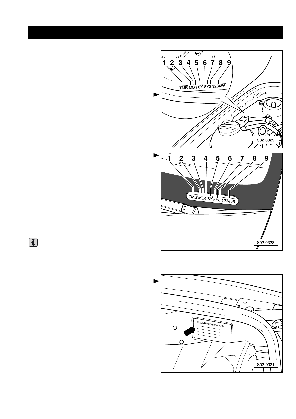
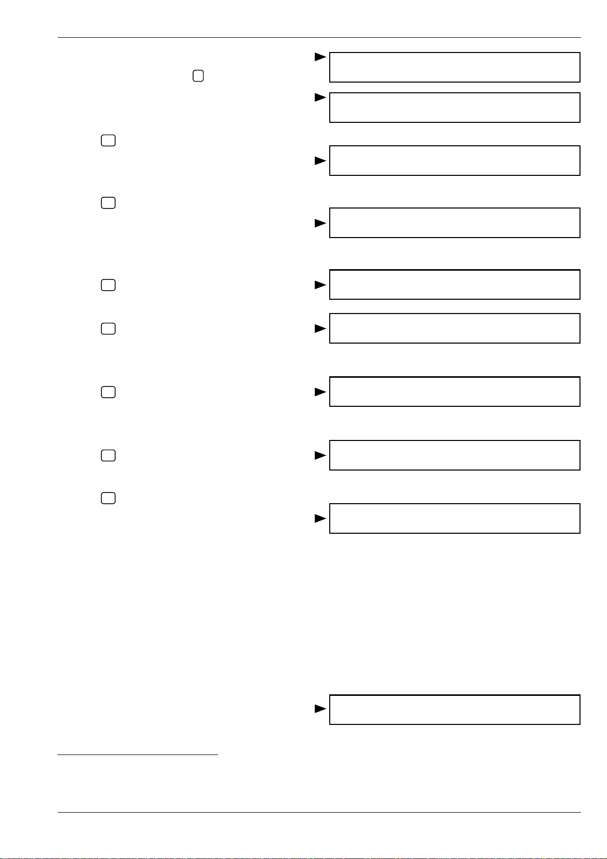
Vehicle identification number
The vehicle identification number (chassis number) is attached to the right suspension dome.
The vehicle identification number (chassis number) can
also be found bottom left of the front window corner.
00
1 - Manufacturer's world code
2 - Model and version
3 - Engine type
4 - Airbag system
5 - Vehicle type
6 - Internal code
7 - Model year
8 - Manufacturing plant
9 - Body number
Note
Detailed information on the meaning of individual signs
⇒ Inspection and Maintenance, Chap. 02-1.
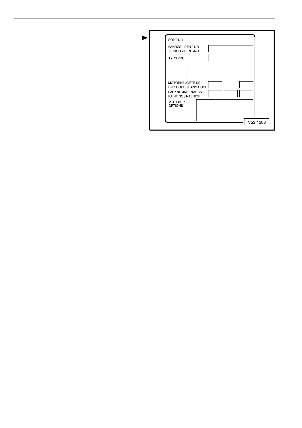
Type plate
The type plate -arrow- is attached to the left wheel house.
S00.5319.03.20
Technical DataEdition 03.00
00-1 page 1
Page 12
00
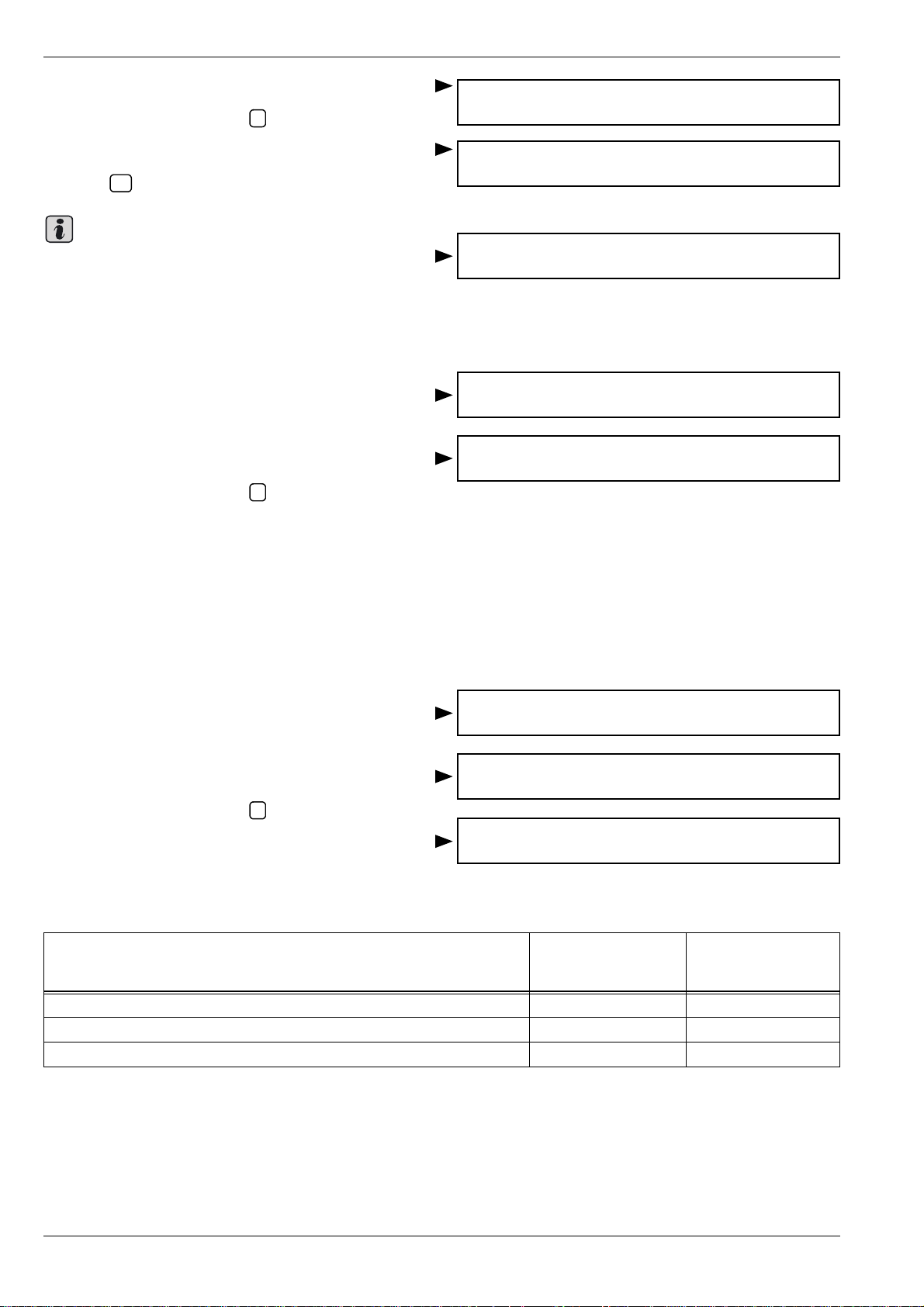
Vehicle data sticker
The vehicle data sticker is located at the rear left on the
floor of the luggage compartment.
FABIA 2000 ³ Body Work
00-1 page 2
Technical Data Edition 03.00
S00.5319.03.20
Page 13
FABIA 2000 ³ Body Work
01 – Self-diagnosis
01-1 Self-diagnosis for con-
venience system
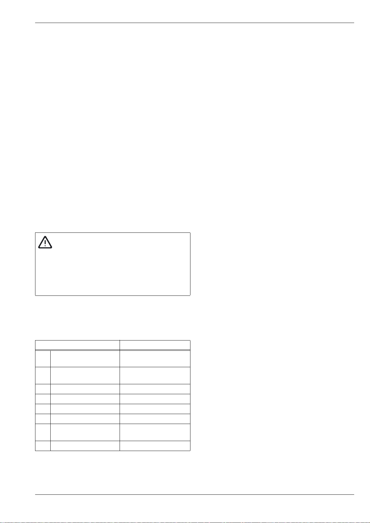
Notes concerning self-diagnosis for convenience system
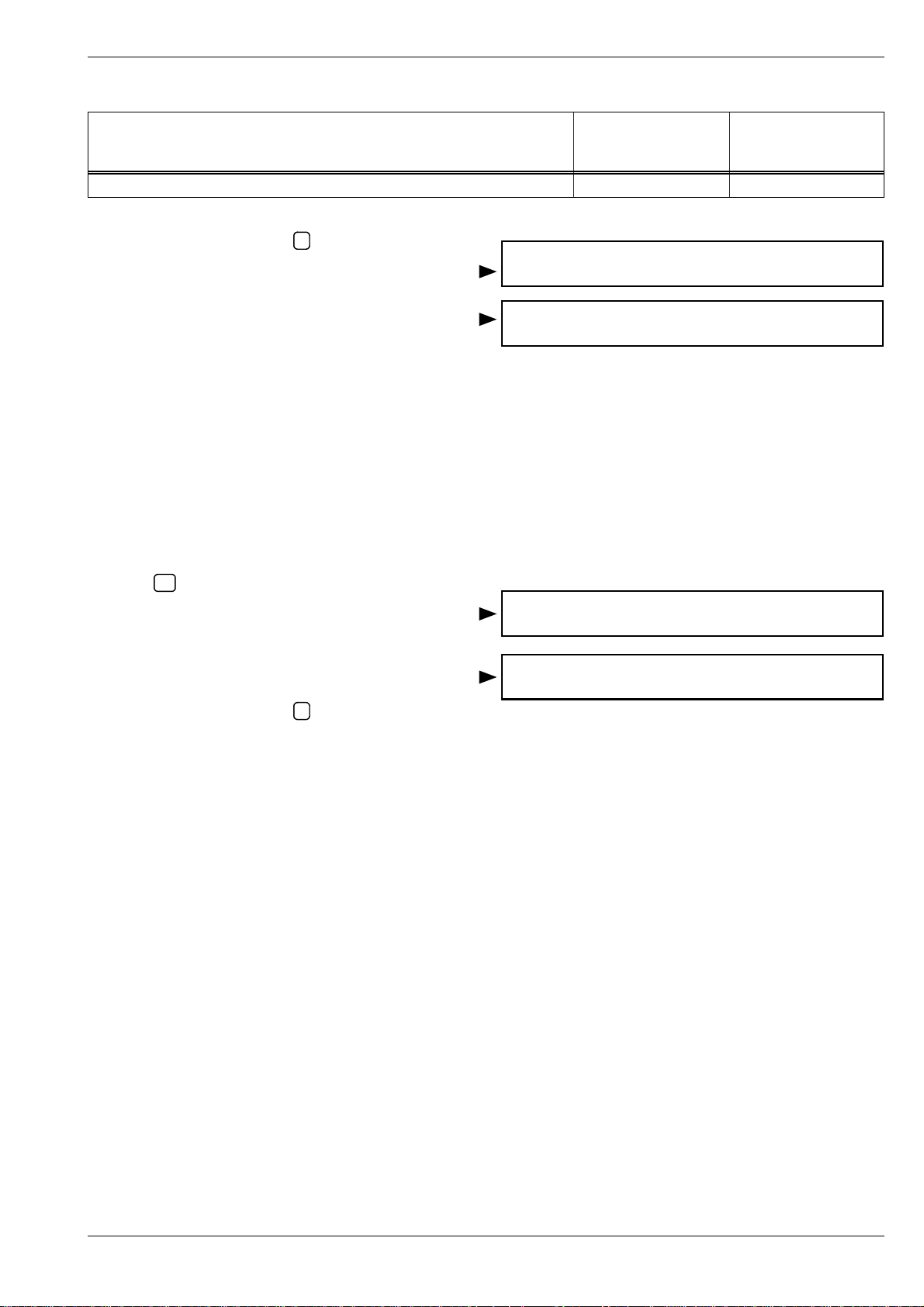
The central control unit for convenience system -J393- is
located above the accelerator pedal in the dash panel. It
is clipped into the bracket on the heating housing. The diagnostic connector is located behind the storage tray under the light switch.
Removing and installing the control unit for convenience
system ⇒ Chap. 70-1.
Initiate self-diagnosis at the start of fault finding and interrogate the fault memory with diagnostic device
-V.A.G 1552- or -V.A.G 1551- or -VAS 5052-.
01
Note
♦ The description which follows relates to the vehicle
system tester -V.A.G 1552- using program card -6.0(and higher version).
♦ The use of fault read-out scan tool -V.A.G 1551- with
program card -9.0- (and later version) is almost identical except for specific deviations (e.g. other display,
possibility of using a printer etc.).
♦ To end the output or to switch to another address se-
lect function 06 „End output“.
WARNING!
When replacing the central control unit for the convenience system or the alarm system with an independent power supply disconnect the power
supply for at least 30 sec. in order to allow the
alarm to be adapted. If necessary, disconnect the
communication cable.
The convenience system can be adapted to the customer
wish ⇒ Chapter 01-4.
Types and description of convenience
system
Two different systems of databus cables are used in the
convenience system:
♦ for vehicles manufactured until 07.2004 the CAN dat-
abus cable
♦ for vehicles manufactured as of 08.2004 the LIN dat-
abus cable
The difference is the operation of the window control,
the fault tables, the measured value blocks and the
coding of the control unit.
Self-diagnosis for convenience systemEdition 01.05
S00.5319.15.20
01-1 page 1
Page 14

01
In case of repairs or self-diagnosis of the convenience system first the system of the communication
cable must be defined. This is detected by means of
the connection of the diagnostic device and by entry
of the address word 46 „Central module co nvenience
system“ ⇒ 01-1 page 4.
Convenience system with CAN databus cable
The convenience system comprises the electric equipment in the doors:
♦ electrical central locking system with SAFE function
♦ power-window lifter with jamming protection
♦ electrically adjustable and heated exterior mirror
It also comprises other systems in the vehicle:
♦ Cut-off delay for interior lamp
♦ Monitoring and disconnection of all interior and lug-
gage compartment lights as a batter y disc ha rg e pr o tection
♦ Sliding roof closing function via outside closing com-
mand
♦ Radio control for anti-theft alarm system and central
locking
♦ the optical Safe function indicator (is a LED mounted
in the door equipment of the driver's door)
FABIA 2000 ³ Body Work
The system comprises the control unit for convenience system and control units in the individual
doors whose communication between each other is
performed via the CAN databus cable. The communication between the central control unit for convenience system and other electrical systems in the
vehicle is performed via the CAN databus cable .
The control unit for convenience system detects
faults in the convenience system (including faults a t
control units in the individual doors) and stores them
in a permanent memory.
The displayed fault messages refer to a fault table including indications on the possible causes as well as targeted
repairs.
Faults due to a temporary line interruption or loose contact are also stored. These faults are displayed as sporadic faults „SP“.
Convenience system with LIN databus cable
The convenience system comprises the electric equipment in the doors:
♦ electrical central locking system with SAFE function
♦ power-window lifter with jamming protection
It also comprises other systems in the vehicle:
01-1 page 2
Self-diagnosis for convenience system Edition 01.05
S00.5319.15.20
Page 15
FABIA 2000 ³ Body Work
♦ Sliding roof closing function via outside closing com-
mand
♦ Radio control for anti-theft alarm system and central
locking
♦ the optical Safe function indicator (is a LED mounted
in the door equipment of the driver's door)
The system comprises the control unit for convenience system. Its communication with other electrical
systems in the vehicle is performed via the CAN databus cable.
Control units are also located in the individual doors,
which however only operate the window lifters. Their
communication is performed via the LIN databus cable.
The LIN databus cable is not self-diagnostic with any
diagnostic device. This cable consists of an independent electrical circuit, which has no connection
to other electrical systems in the vehicle.
The control unit for convenience system detects
faults in the convenience system (including faults in
the individual doors relating to the lock) and stores
them in a permanent memory. The faults relating to
the window control can be stored in the fault memory
of the convenience system.
01
WARNING!
If the window control is restricted or fully non-operational, proceed according to „functionality of
individual windows“ ⇒ Chap. 01-3, Fault table LIN
databus/control units for window control in the individual doors. This table is used for the diagnosis
of faults from the LIN databus.
Overview of the selectable functions of
the diagnosis for the convenience system
Operation Page
01 Interrogating control
unit version
02 Interrogating fault
memory
03 Actuator diagnosis ⇒ 01-1 page 6
05 Erasing fault memory ⇒ 01-1 page 7
06 Ending output ⇒ 01-1 page 8
07 Coding control unit ⇒ 01-1 page 8
08 Reading measured val-
ue block
10 Adjustment ⇒ Chapter 01-4
⇒ 01-1 page 5
⇒ 01-1 page 6
⇒ Chap. 01-2,
⇒ Chap. 01-3
S00.5319.15.20
Self-diagnosis for convenience systemEdition 01.05
01-1 page 3
Page 16
01
Connect vehicle system tester
-V.A.G 1552-
Special tools, test and measuring equipment and
auxiliary items required
♦ Vehicle system tester -V.A.G 1552-
♦ Diagnostic cable -V.A.G 1551/3, 3A, 3B, 3C-
Test conditions
• All fuses must be OK in compliance with the current
flow diagram.
• Battery voltage at least 9 V.
Procedure
– Open the storage tray -1- under the light switch -ar-
row-.
– Switch off ignition and connect vehicle system tester
-V.A.G 1552-.
– Switch on ignition.
Readout on display:
– Select address word 46 „Central module convenience
system“.
Readout on display:
– Confirm the entry with key .
Readout on display:
Q
FABIA 2000 ³ Body Work
3
2
1
6
5
4
9
8
7
E
H
Q
O
C
Vehicle system test HELP
Enter address word XX
Vehicle system test Q
46 Central module convenience system
Vehicle system test
Tester sends address word 46
2
5
5
1
.
G
.
A
.
V
P
L
Note
♦ One of the following four displays will appear in the
event of a communication set-up failure between vehicle system tester -V.A.G 1552- and the control unit.
♦ Press key to display the possible fault causes.
HELP
The ignition must be on!
Malfunctions occurred at the start of or during the pro-
gram (external sources of interference).
– Check connection of the vehicle system tester
-V.A.G 1552-.
– After removing the possible fault causes re-enter ad-
dress word 46 „Central module convenience system“
and confirm entry with .
Read-out on display after entering address word „46“:
The display shows the control unit identification number,
e.g.:
– Press key.
→
Q
Vehicle system test HELP
The control unit does not respond
Vehicle system test HELP
K cable does not connect to pos. term.
Vehicle system test →
No signal from the control unit
Vehicle system test →
Fault in communication set-up
Vehicle system test
Tester sends address word 46
6Q0959433C OM convenience unit 0002 →
Coding 00259 WSCXXXXX
01-1 page 4
Self-diagnosis for convenience system Edition 01.05
S00.5319.15.20
Page 17
FABIA 2000 ³ Body Work
01
The following display relates to the system with LIN
databus cable:
In this case continue the self-diagnosis ⇒ Chap. 01-
3.
The following display relates to the system with CAN
databus cable:
Readout on display, e.g.: (Door control unit driver's side)
In this case continue the self-diagnosis ⇒ Chap. 01-
2.
– Press key.
→
Readout on display, e.g.: (Door control unit passenger's
side)
– Press key.
→
Readout on display, e.g.: (Door control unit RL)
– Press key.
→
Readout on display, e.g.: (RR door control unit)
– Press key.
→
Readout on display:
Vehicle system test HELP
Select function XX
6Q1959801 OM D.contr unit DDCU TFK 0001→
6Q1959802 OM D.contr unit PDCU TFK 0001→
6Q1959811 OM D.contr unit RL TFK 0001→
6Q1959812 OM D. contr unit RR TFK 0001→
Vehicle system test HELP
Select function XX
Interrogating control unit version
– Connecting vehicle system tester -V.A.G 1552- and
selecting the address word for the convenience system ⇒ 01-1 page 4.
Readout on display:
– Select function 01 and confirm entry with .
Readout on display:
The control unit identification appears in the display of the
vehicle system tester -V.A.G 1552- e.g.:
♦ 6Q0959433 OM = Part No. of the control unit (current
control unit version ⇒ Electronic catalogue of original
parts)
♦ Convenience unit = system description
♦ 0002; (TFK 0001) = Program number
♦ Coding 00259 = Coding variant
♦ WSC = Workshop code
– Press key.
Readout on display, e.g.: (Door control unit driver's side)
– Press key.
Readout on display, e.g.: (Door control unit passenger's
side)
→
→
Q
Vehicle system test HELP
Select function XX
Vehicle system test Q
01 - Interrogating control unit version
6Q0959433C OM convenience unit 0002 →
Coding 00259 WSC XXXXX
6Q1959801 OM door control.DD TFK 0001→
6Q1959802 OM door control.PD TFK 0001→
– Press key.
→
Readout on display, e.g.: (Door control unit RL)
Self-diagnosis for convenience systemEdition 01.05
S00.5319.15.20
6Q1959811 OM door control.RL TFK 0001→
01-1 page 5
Page 18
01
FABIA 2000 ³ Body Work
– Press key.
Readout on display, e.g.: (RR door control unit)
– Press key.
Readout on display:
→
→
– Ending output ⇒ 01-1 page 8.
Interrogating fault memory
– Connecting vehicle system tester -V.A.G 1552- and
selecting the address word for the convenience system ⇒ 01-1 page 4.
Readout on display:
– Select function 02.
Readout on display:
– Confirm the entry with key .
The number of faults stored appears on the display.
Press key to display the stored faults consecutively.
→
Q
6Q1959812 OM door control.RR TFK 0001→
Vehicle system test HELP
Select function XX
Vehicle system test HELP
Select function XX
Vehicle system test Q
02 - Interrogating fault memory
X faults detected →
Cause and elimination:
Convenience system with CAN databus cable ⇒ Chap.
01-2.
Convenience system with LIN databus cable ⇒ Chap.
01-3.
Note
♦ If a fault is detected:
♦ 1. Remove fault.
♦ 2. Erase fault memory (Function 05).
♦ 3. Perform a functional test of the convenience sys-
tem.
♦ 4. Interrogate fault memory (Function 02) again.
If „No fault detected“ the program returns to its initial position after key is pressed.
Readout on display:
If anything else appears on the display: ⇒ Operating in-
structions of the vehicle system tester.
→
– Ending output ⇒ 01-1 page 8.
No fault detected! →
– Switch off ignition and switch off vehicle system tester.
Actuator diagnosis
– Connecting vehicle system tester -V.A.G 1552- and
selecting the address word for the convenience system ⇒ 01-1 page 4.
Readout on display:
01-1 page 6
Self-diagnosis for convenience system Edition 01.05
Vehicle system test HELP
Select function XX
S00.5319.15.20
Page 19
FABIA 2000 ³ Body Work
01
– Enter function 03.
– Confirm the entry with key .
Readout on display:
Door handle switches are lit.
– Press key.
Readout on display:
Warning lamp in door trim panel flashes.
– Press key.
Readout on display:
Exit warning light lights up.
Readout on display:
– Press key.
Sliding roof closes.
– Press key.
Turn signals on.
→
→
→
2)
→
3)
Q
1)
Vehicle system test Q
03 Actuator diagnosis
Actuator diagnosis →
Inside door handle lighting
Actuator diagnosis →
CL warning lamp Safe
Actuator diagnosis →
Exit warning light
Actuator diagnosis →
Close sliding roof signal
Actuator diagnosis →
Turn signal control
Readout on display:
– Press key.
Alarm horn activated.
→
3)
Readout on display:
– Press key.
→
Readout on display:
– Press key.
→
Readout on display:
– Ending output ⇒ 01-1 page 8.
Erasing fault memory
Conditions:
♦ Fault memory was interrogated.
♦ Fault was eliminated.
♦ Functional test was performed.
– Connecting vehicle system tester -V.A.G 1552- and
selecting the address word for the convenience system ⇒ 01-1 page 4.
Readout on display:
– Enter function 05.
Actuator diagnosis →
Alarm horn - H12
Actuator diagnosis →
END
Function unknown or cannot →
be carried out at the moment
Vehicle system test HELP
Select function XX
1)
Not fitted on FABIA.
2)
Only on vehicles equipped with sliding roof.
3)
Only on vehicles with remote control or alarm function.
S00.5319.15.20
Self-diagnosis for convenience systemEdition 01.05
01-1 page 7
Page 20
01
FABIA 2000 ³ Body Work
Readout on display:
– Confirm the entry with key .
Readout on display:
– Press key.
♦ If the following message is displayed the test se-
quence is incorrect:
♦ Carefully follow the test sequence step by step: First
interrogate the fault memory and then erase.
→
Note
Q
Ending output
Readout on display:
– Enter function 06.
Readout on display:
– Confirm the entry with key .
– Switch off ignition.
Q
Vehicle system test Q
05 Erase fault memory
Vehicle system test →
The fault memory is erased
Caution!
Fault memory was not interrogated
Vehicle system test
Select function XX
Vehicle system test Q
06 End output
– Disconnect vehicle system tester -V.A.G 1552- from
the connector.
Coding control unit
– Connecting vehicle system tester -V.A.G 1552- and
selecting the address word for the convenience system ⇒ 01-1 page 4.
Readout on display:
– Enter function 07.
Readout on display:
– Confirm the entry with key .
Readout on display:
Q
– Enter code number following table:
Table of codes for vehicles with CAN databus cable
Vehicle equipment Code number indi-
Central locking without power-window lifter 00018 00019
Central locking with 2 power-window lifters 00066 00067
Central locking with 4 power-window lifters 00258 00259
Vehicle system test HELP
Select function XX
Vehicle system test Q
07 Coding control unit
Coding control unit
Enter code number XXXXX (0-32767)
Code number over-
vidual door open-
ing
all door opening
01-1 page 8
Self-diagnosis for convenience system Edition 01.05
S00.5319.15.20
Page 21
FABIA 2000 ³ Body Work
Table of codes for vehicles with LIN databus cable
01
Vehicle equipment Code numbe r indi-
vidual door open-
ing
Central locking without power-window lifter 00018 00019
– Confirm the entry with key .
The control unit identification number, the control unit
code number and the workshop code are displayed.
If the control unit rejects an entered code number the following message will be displayed:
In this case the control unit was not coded with the data
required for the vehicle. Check whether the right control
unit was fitted on the vehicle (compare part number and
character index), or whether possibly a wrong co de was
entered.
Q
6Q09959433 OM convenience unit. 0002
Coding 00259 WSC xxxxx
Fault →
Coding XXXXX not accepted
Code number over-
all door opening
– Repeat coding.
If the control unit cannot be coded (correct control unit,
correct code number) the control unit is defective.
End funtion:
– Press key.
Readout on display:
→
– Enter function 06.
Readout on display:
– Confirm the entry with key .
Q
Vehicle system test HELP
Select function XX
Vehicle system test Q
06 End output
S00.5319.15.20
Self-diagnosis for convenience systemEdition 01.05
01-1 page 9
Page 22

01
FABIA 2000 ³ Body Work
01-1 page 10
Self-diagnosis for convenience system Edition 01.05
S00.5319.15.20
Page 23

FABIA 2000 ³ Body Work
01-2 Self-diagnosis for con-
venience system with
CAN databus cable
Overview of the selectable functions of
the self diagnosis for convenience system with CAN databus cable
Operation Page
01 Interrogating control
unit version
02 Interrogating fault
memory
03 Actuator diagnosis ⇒ Chapter 01-1
05 Erasing fault memory ⇒ Chapter 01-1
06 Ending output ⇒ Chapter 01-1
07 Coding control unit ⇒ Chap. 01-1 ⇒ 01-2
08 Reading measured val-
ue block
10 Adjustment ⇒ Chapter 01-4
⇒ Chap. 01-1,
⇒ Chapter 01-1
page 3
⇒ 01-2 page 15
01
Overview of the control units for convenience system with CAN databus cable
Control unit part No.
Central control
unit for convenience system
6Q0959433A 01
6Q0959433H 35
6Q0959433C 02
6Q0959433E 3A
6Q0959433C OK - 0002 Control unit without power-window lifter, with radio con-
6Q0959433C 03
6Q0959433E 2P
6Q0959433A 04
6Q0959433H 2Q 6Q1959 801 04/2Q
6Q0959433C 06
6Q0959433E 2S 6Q1959801 06/2S
6Q0959433C 08
6Q0959433E 2U 6Q1959801 08/2U
Door control unit
6Q1959 802 04/2Q
6Q1959802 06/2S
6Q1959802 08/2U
1)
- 0002 Control unit without power-window lifter, without radio
- 0002 Control unit without power-window lifter, with radio con-
- 0002 Control unit without power-window lifter, with radio con-
Program
number
0002
TFK 0001
0002
TFK 0001
0002
TFK 0001
Control unit function
control and without alarm function
LHD
trol without alarm function
LHD
trol and alarm function (with interior monitoring) without
alarm system with independent power supply
LHD
trol and alarm function (with interior monitoring) and
alarm system with independent power supply
LHD
Control unit with 2 power-window lifters, without radio
control and alarm function
LHD
Control unit with 2 power-window lifters, with radio control and without alarm function
LHD
Control unit with 2 power-window lifters, with radio control and alarm function (with interior monitoring) and
alarm system with independent power supply
LHD
S00.5319.15.20
Self-diagnosis for convenience system with CAN databus cableEdition 01.05
01-2 page 1
Page 24

01
FABIA 2000 ³ Body Work
Control unit part No.
Central control
unit for convenience system
6Q0959433C OL
6Q0959433E OL 6Q1959801 OL
6Q0959433A 05
6Q0959433H 2R 6Q1959801 05/2R
6Q0959433C 07
6Q0959433E 2T 6Q1959801 07
6Q0959433C 09
6Q0959433E 2V 6Q1959801 09/2V
6Q0959433C OM
6Q0959433E OM 6Q1959801 OM
6Q0959433A 0A
6Q0959433H 2E
6Q0959433C 0B
6Q0959433E 2X
6Q0959433F 2X
6Q0959433C 0C
6Q0959433E 2Y
6Q0959433A 0D
6Q0959433H 2Z 6Q1959801 0D/2Z
6Q0959433C 0F
6Q0959433E 31
6Q0959433F 31
6Q0959433C 0H
6Q0959433H 33 6Q1959801 0H/33
6Q0959433A 0E
6Q0959433H 30 6Q1959801 0E30
6Q0959433C 0G
6Q0959433E 32
6Q0959433F 32
Door control unit
6Q1959802 OL
6Q1959802 05/2R
6Q1959811 05
6Q1959812 05
6Q1959802 07/2T
6Q1959811 07/2T
6Q1959812 07
6Q1959802 09/2V
6Q1959811 09/2V
6Q1959812 09/2V
6Q1959 02 OM
6Q1959811 OM
6Q1959812 OM
6Q1959802 0D/2Z
6Q1959801 0F/31
6Q0959802 0F/31
6Q0959802 0H/33
6Q1959802 0E/30
6Q1959811 0E/30
6Q1959 812 0E/30
6Q1959801 0G/32
6Q1959802 0G/32
6Q1959811 0G/32
6Q1959812 0G/32
1)
- 0002 Control unit without power-window lifter, without radio
- 0002 Control unit without power-window lifter, with radio con-
- 0002 Control unit without power-window lifter, with radio con-
Program
number
0002
TFK 0001
0002
TFK 0001
0002
TFK 0001
0002
TFK 0001
0002
TFK 0001
0002
TFK 0001
0002
TFK 0001
0002
TFK 0001
0002
TFK 0001
0002
TFK 0001
Control unit function
Control unit with 2 power-window lifters, with radio control and alarm function (with interior monitoring) without
alarm system with independent power supply
LHD
Control unit with 4 power-window lifters, without radio
control and alarm function
LHD
Control unit with 4 power-window lifters, with radio control and without alarm function
LHD
Control unit with 4 power-window lifters, with radio control and alarm function (with interior monitoring) and
alarm system with independent power supply
LHD
Control unit with 4 power-window lifters, with radio control and alarm function (with interior monitoring) without
alarm system with independent power supply
LHD
control and without alarm function
RHD
trol and without alarm function
RHD
trol and alarm function (with interior monitoring) and
alarm system with independent power supply
RHD
Control unit with 2 power-window lifters, without radio
control and alarm function
RHD
Control unit with 2 power-window lifters with radio control and without alarm function
RHD
Control unit with 2 power-window lifters, with radio control and alarm function (with interior monitoring) and
alarm system with independent power supply
RHD
Control unit with 4 power-window lifters, without radio
control and alarm function
RHD
Control unit with 4 power-window lifters with radio control and without alarm function
RHD
01-2 page 2
Self-diagnosis for convenience system with CAN databus cable Edition 01.05
S00.5319.15.20
Page 25

FABIA 2000 ³ Body Work
01
Control unit part No.
Central control
unit for convenience system
6Q0959433C 0J
6Q0959433E 34 6Q1959801 0J/34
6Q0959433C 0N
6Q0959433G 3B 6Q1959801 09/3B
6Q0959433G 36
6Q0959433 F 37 0002
6Q0959433F 38
6Q0959433F 39
1)
Current control unit version ⇒ electronic catalogue of original parts
Door control unit
6Q1959802 0J/34
6Q1959811 0J/34
6Q1959812 0J/34
6Q1959802 09/3B
6Q1959811 09/3B
6Q1959812 09/3B
6Q1959801 36
6Q1959802 36
6Q1959801 38
6Q1959802 38
6Q1959801 39
6Q1959802 39
6Q1959811 39
6Q1959812 39
1)
Program
number
0002
TFK 0001
0002
TFK 0001
0002
TFK 0001
TFK 0001
0002
TFK 0001
0002
TFK 0001
Control unit function
Control unit with 4 power-window lifters, with radio control and alarm function (with interior monitoring) and
alarm system with independent power supply
RHD
Control unit with 2 power-window lifters, without radio
control and alarm function
LHD
Control unit with 2 power-window lifters, without radio
control and alarm function
RHD
Control unit without power-window lifter, with 315 MHz
radio control and alarm function (with interior monitoring) and alarm system with independent power supply
RHD
Control unit with 2 power-window lifters, with 315 MHz
radio control and alarm function (with interior monitoring) and alarm system with independent power supply
RHD
Control unit with 4 power-window lifters, with 315 MHz
radio control and alarm function (with interior monitoring) and alarm system with independent power supply
RHD
Coding control unit with CAN databus
cable
– Connecting vehicle system tester -V.A.G 1552- and
selecting function 07 „code control unit“. ⇒ Chap. 01-
1.
– Enter code number following table:
Vehicle equipment Code numbe r indi-
vidual door open-
ing
Central locking without power-window lifter 00018 00019
Central locking with 2 power-window lifters 00066 00067
Central locking with 4 power-window lifters 00258 00259
Code number over-
all door opening
S00.5319.15.20
Self-diagnosis for convenience system with CAN databus cableEdition 01.05
01-2 page 3
Page 26

01
Fault table Convenience system with
CAN databus cable
Note
♦ Below is a list of all possible faults detected by the
central control unit for convenience system -J393- and
displayed on -V.A.G 1552 -, arranged according to
their 5-digit fault code.
♦ SAE code, may be displayed on the right next to the
fault number (e.g. 4214), ignore.
♦ If „Info in literature“ appears in the display of the vehi-
cle system tester, look for the text required in the fault
table under the fault code.
♦ After repair always interrogate the fault memory using
vehicle system tester -V.A.G 1552- and erase the
memory.
♦ If parts are output as faulty: First check all cables and
connectors to these components as well as the earth
connections according to the Current Flow Diagram.
Then check whether all plug connections are properly
plugged into the relay plate. Replace the component
only if this test does not reveal any fault. This applies
in particular if faults are shown as „sporadic“ (SP).
FABIA 2000 ³ Body Work
Display on V.A.G. 1552 Possible cause of fault Rectifying fault
65535
no fault detected
00849
S contact on ignition starter
switch D -D-
00912
Switch for FL
window lifter
-E40-
00913
Switch for FR
window lifter,
driver's side
-E81-
undefined switch
status
Implausible signal
Implausible signal
If after repair „No fault detected“ is displayed, the self-diagnosis is completed.
♦ Terminal 15 O.K., S contact de-
fective
♦ Cables or plug connections de-
fective
♦ Cables or plug connections de-
fective
♦ Switch for FL window lifter -E40-
defective at central switch
♦ Switch for FL window lifter -E40-
loose at central switch
♦ Cables or plug connections de-
fective
♦ Switch for FR window lifter -E81-
defective at central switch
♦ Switch for FR window lifter -E81-
loose at central switch
– Reading measured value block
⇒ 01-2 page 16
– Check wiring and plug connec-
tions according to the current flow
diagram
– Check wiring and plug connec-
tions according to the current flow
diagram
– Replace central switch for win-
dow lifter
– Check switch FL fastening
– Reading measured value block
⇒ 01-2 page 16
– Check wiring and plug connec-
tions according to the current flow
diagram
– Replace central switch for win-
dow lifter
– Check switch FR fastening
– Reading measured value block
⇒ 01-2 page 16
01-2 page 4
Self-diagnosis for convenience system with CAN databus cable Edition 01.05
S00.5319.15.20
Page 27

FABIA 2000 ³ Body Work
Display on V.A.G. 1552 Possible cause of fault Rectifying fault
00914
Switch for RL
window lifter,
driver's side
-E53-
00915
Switch for RR
window lifter,
driver's side
-E55-
00928
Locking unit for
CL driver's side
-F220-
00929
Locking unit for
CL front passenger's side
-F221-
Implausible signal
Implausible signal
Implausible signal
wrong equipment
Implausible signal
wrong equipment
♦ Cables or plug connections de-
fective
♦ Switch for RL window lifter -E53-
defective at central switch
♦ Switch for RL window lifter -E53-
loose at central switch
♦ Cables or plug connections de-
fective
♦ Switch for RR window lifter -E55-
defective at central switch
♦ Switch for RR window lifter -E55-
loose at central switch
♦ Locking unit defective
♦ Cables or plug connections de-
fective
♦ No supply voltage for CL on driv-
er's door
♦ Resistance in the mechanism of
the locking unit and control elements
♦ other locking unit type fitted
♦ Locking unit defective
♦ Cables or plug connections de-
fective
♦ No supply voltage for CL on pas-
senger's door
♦ Resistance in the mechanism of
the locking unit and control elements
♦ other locking unit type fitted
1)
1)
– Check wiring and plug connec-
tions according to the current flow
diagram
– Replace central switch for win-
dow lifter
– Check switch RL fastening
– Reading measured value block
⇒ 01-2 page 16
– Check wiring and plug connec-
tions according to the current flow
diagram
– Replace central switch for win-
dow lifter
– Check switch RR fastening
– Reading measured value block
⇒ 01-2 page 16
– Reading measured value block
⇒ 01-2 page 16
– Replace locking unit
– Check wiring and plug connec-
tions according to the current flow
diagram
– Check supply voltage
– Check mechanism and ensure
smooth operation
– Replace locking unit
– Reading measured value block
⇒ 01-2 page 16
– Replace locking unit
– Check wiring and plug connec-
tions according to the current flow
diagram
– Check supply voltage
– Check mechanism and ensure
smooth operation
– Replace locking unit
01
S00.5319.15.20
Self-diagnosis for convenience system with CAN databus cableEdition 01.05
01-2 page 5
Page 28

01
Display on V.A.G. 1552 Possible cause of fault Rectifying fault
00930
Locking unit for
RL CL -F222-
00931
Locking unit for
CL rr -F223-
00932
Window lifter
motor driver's
side -V147-
00933
Window lifter
motor passenger's side
-V148-
Implausible signal ♦ Locking unit defective
♦ Cables or plug connections de-
fective
♦ No supply voltage for CL on rear
left door
♦ Resistance in the mechanism of
the locking unit and control elements
wrong equipment
Implausible signal
wrong equipment
No setting or incor-
rect setting
No setting or incorrect setting
♦ other locking unit type fitted
♦ Locking unit defective
♦ Cables or plug connections de-
fective
♦ No supply voltage for CL on rear
right door
♦ Resistance in the mechanism of
the locking unit and control elements
♦ other locking unit type fitted
♦ missing or incorrectly set window
lifter mechanism
♦ Window lifter motor driver's side
-V147- defective
♦ Cables or plug connections de-
fective
♦ No supply voltage for CL on driv-
er's door
♦ Resistance in window lifter
mechanism
♦ missing or incorrectly set window
lifter mechanism
♦ Window lifter motor passenger's
side -V148- defective
♦ Cables or plug connections de-
fective
♦ No supply voltage for CL on pas-
senger's door
♦ Resistance in window lifter
mechanism
2)
2)
– Reading measured value block
– Replace locking unit
– Check wiring and plug connec-
– Check supply voltage
– Check mechanism and ensure
1)
– Replace locking unit
– Reading measured value block
– Replace locking unit
– Check wiring and plug connec-
– Check supply voltage
– Check mechanism and ensure
1)
– Replace locking unit
– Initialisation for automatic lift/low-
– Replace window lifter motor driv-
– Check wiring and plug connec-
– Check supply voltage
– Check mechanism and ensure
– Initialisation for automatic lift/low-
– Replace window lifter motor pas-
– Check wiring and plug connec-
– Check supply voltage
– Check mechanism and ensure
FABIA 2000 ³ Body Work
⇒ 01-2 page 16
tions according to the current flow
diagram
smooth operation
⇒ 01-2 page 16
tions according to the current flow
diagram
smooth operation
er lift mechanism
er's side -V147-
tions according to the current flow
diagram
smooth operation
er lift mechanism
senger's side -V148-
tions according to the current flow
diagram
smooth operation
01-2 page 6
Self-diagnosis for convenience system with CAN databus cable Edition 01.05
S00.5319.15.20
Page 29

FABIA 2000 ³ Body Work
Display on V.A.G. 1552 Possible cause of fault Rectifying fault
00934
Window lifter
motor rl -V26-
00935
Window lifter
motor RR -V27-
00936
Window lifter
switch passenger's side
-E107-
00937
Window lifter
switch RL -E52-
00938
Window lifter
switch RR -E54-
No setting or incorrect setting
No setting or incorrect setting
Implausible signal
♦ missing or incorrectly set window
lifter mechanism
♦ Window lifter motor RL -V26- de-
fective
♦ Cables or plug connections de-
fective
♦ No supply voltage for CL on rear
left door
♦ Resistance in window lifter
mechanism
♦ missing or incorrectly set window
lifter mechanism
♦ Window lifter motor RR -V27-
defective
♦ Cables or plug connections de-
fective
♦ No supply voltage for CL on rear
right door
♦ Resistance in window lifter
mechanism
♦ Window lifter switch passen-
ger's side -E107- defective
♦ Cables or plug connections de-
fective
♦ Window lifter switch passen-
ger's side -E107- loose
♦ Window lifter switch RL -E52-
defective
♦ Cables or plug connections de-
fective
♦ Window lifter switch RL -E52-
loose
♦ Window lifter switch RR -E54-
defective
♦ Cables or plug connections de-
fective
♦ Window lifter switch RR -E54-
loose
2)
2)
– Initialisation for automatic lift/low-
er lift mechanism
– Replace window lifter motor RL
-V26-
– Check wiring and plug connec-
tions according to the current flow
diagram
– Check supply voltage
– Check mechanism and ensure
smooth operation
– Initialisation for automatic lift/low-
er lift mechanism
– Replace window lifter motor RR
-V27-
– Check wiring and plug connec-
tions according to the current flow
diagram
– Check supply voltage
– Check mechanism and ensure
smooth operation
– Replace window lifter switch pas-
senger's side -E107-
– Check wiring and plug connec-
tions according to the current flow
diagram
– Check switch fastening
– Reading measured value block
⇒ 01-2 page 16
– Replace window lifter motor RL
-E52-
– Check wiring and plug connec-
tions according to the current flow
diagram
– Check switch fastening
– Reading measured value block
⇒ 01-2 page 16
– Replace window lifter switch RR
-E54-
– Check wiring and plug connec-
tions according to the current flow
diagram
– Check switch fastening
– Reading measured value block
⇒ 01-2 page 16
01
S00.5319.15.20
Self-diagnosis for convenience system with CAN databus cableEdition 01.05
01-2 page 7
Page 30

01
Display on V.A.G. 1552 Possible cause of fault Rectifying fault
00939
Replace mirror
adjustment motor driver's side
-V149-
00940
Mirror adjustment motor passenger's side
-V150-
00948
Close sliding
roof signal
Short circuit to positive
♦ Replace mirror adjustment motor
driver's side -V149- defective
♦ Cables or plug connections de-
fective
♦ No supply voltage on driver's
door
♦ Replace mirror adjustment motor
passenger's side -V150- defective
♦ Cables or plug connections de-
fective
♦ No supply voltage on passen-
ger's door
♦ Cables or plug connections de-
fective
♦ Sliding roof switch defective
– Replace mirror adjustment motor
– Check wiring and plug connec-
– Check supply voltage
– Replace mirror adjustment motor
– Check wiring and plug connec-
– Check supply voltage
– Check wiring and plug connec-
FABIA 2000 ³ Body Work
Replace driver's side -V149-
tions according to the current flow
diagram
passenger's side -V150-
tions according to the current flow
diagram
tions according to the current flow
diagram
– Replace sliding roof switch
♦ Sliding roof motor defective
– Replace sliding roof motor
00949
Motor for CL
tailgate -V53-,
LOCK
00950
Motor for CL
tailgate -V53-,
UNLOCK
00955
Key 1
00956
Key 2
00957
Key 3
undefined switch
status
undefined switch
status
Adaptation threshold (mul) exceeded
Adaptation threshold (mul) exceeded
Adaptation threshold (mul) exceeded
♦ Motor for CL tailgate defective
♦ Cables or plug connections de-
fective
♦ Resistance in lock control mech-
anism
♦ Motor for CL tailgate defective
♦ Cables or plug connections de-
fective
♦ Resistance in lock control mech-
anism
♦ Key not adapted
♦ Key was operated over 200
times outside the reception
range
♦ Key not adapted
♦ Key was operated over 200
times outside the reception
range
♦ Key not adapted
♦ Key was operated over 200
times outside the reception
range
– Replace motor for CL tailgate
– Check wiring and plug connec-
tions according to the current flow
diagram
– Check lock control mechanism
and ensure smooth operation
– Replace motor for CL tailgate
– Check wiring and plug connec-
tions according to the current flow
diagram
– Check lock control mechanism
and ensure smooth operation
– Reading measured value block
⇒ 01-2 page 16
– Perform adaptation ⇒ Chap. 01-4
– Reading measured value block
⇒ 01-2 page 16
– Perform adaptation ⇒ Chap. 01-4
– Reading measured value block
⇒ 01-2 page 16
– Perform adaptation ⇒ Chap. 01-4
01-2 page 8
Self-diagnosis for convenience system with CAN databus cable Edition 01.05
S00.5319.15.20
Page 31

FABIA 2000 ³ Body Work
Display on V.A.G. 1552 Possible cause of fault Rectifying fault
00958
Key 4
01030
Lock the CL key
switch on the
driver's side
01031
Unlock the CL
key switch on
the driver's side
01032
Lock the CL key
switch on the
passenger's
side
01033
Unlock the CL
key switch on
the passenger's
side
01034
Window lifter:
Activation of
thermo fuse,
driver's side
01035
Window lifter:
Activation of
thermo fuse,
front passenger's side
01036
Window lifter:
Activation of
thermo fuse, RL
Adaptation threshold (mul) exceeded
Short circuit to
earth
Short circuit to
earth
Short circuit to
earth
Short circuit to
earth
♦ Key not adapted
♦ Key was operated over 200
times outside the reception
range
♦ Cables or plug connections de-
fective
♦ Lock cylinder defective
♦ Lock cylinder loose
♦ Cables or plug connections de-
fective
♦ Lock cylinder defective
♦ Lock cylinder loose
♦ Cables or plug connections de-
fective
♦ Lock cylinder defective
♦ Lock cylinder loose
♦ Cables or plug connections de-
fective
♦ Lock cylinder defective
♦ Lock cylinder loose
♦ Cables or plug connections de-
fective
♦ Window lifter mechanism loose
or stiff
♦ Resistance in window lifter motor
♦ Resistance in the window run
during lifting and lowering of
door window
♦ Cables or plug connections de-
fective
♦ Window lifter mechanism loose
or stiff
♦ Resistance in window lifter motor
♦ Resistance in the window run
during lifting and lowering of
door window
♦ Cables or plug connections de-
fective
♦ Window lifter mechanism loose
or stiff
♦ Resistance in window lifter motor
♦ Resistance in the window run
during lifting and lowering of
door window
– Reading measured value block
⇒ 01-2 page 16
– Perform adaptation ⇒ Chap. 01-4
– Reading measured value block
⇒ 01-2 page 16
– Replace lock cylinder
– Check lock cylinder installation
– Reading measured value block
⇒ 01-2 page 16
– Replace lock cylinder
– Check lock cylinder installation
– Reading measured value block
⇒ 01-2 page 16
– Replace lock cylinder
– Check lock cylinder installation
– Reading measured value block
⇒ 01-2 page 16
– Replace lock cylinder
– Check lock cylinder installation
– Reading measured value block
⇒ 01-2 page 16
– Check window lifter mechanism
– Check window lifter motor
– Eliminate obstacle
– Reading measured value block
⇒ 01-2 page 16
– Check window lifter mechanism
– Check window lifter motor
– Eliminate obstacle
– Reading measured value block
⇒ 01-2 page 16
– Check window lifter mechanism
– Check window lifter motor
– Eliminate obstacle
01
S00.5319.15.20
Self-diagnosis for convenience system with CAN databus cableEdition 01.05
01-2 page 9
Page 32

01
Display on V.A.G. 1552 Possible cause of fault Rectifying fault
01037
Window lifter:
Activation of
thermo fuse, RR
01038
Central lokking
thermo fuse
01044
Control unit
wrongly coded
01134
Alarm horn
-H12-
01135
Sensors for interior monitoring
01179
Key programming, wrong
01312
Databus drive
01322
Control unit for
multi-function
unit
undefined switch
status
defective
No communication
internal power supply
Open circuit
defective
please read out
fault memory
No communication
please read out
fault memory
♦ Cables or plug connections de-
fective
♦ Window lifter mechanism loose
or stiff
♦ Resistance in window lifter motor
♦ Resistance in the window run
during lifting and lowering of
door window
♦ Cables or plug connections de-
fective
♦ Resistance in door lock
♦ another control unit used
♦ Control unit wrongly coded
♦ Cables or plug connections de-
fective
♦ Alarm horn defective
♦ Cables or plug connections de-
fective
♦ Alarm system with independent
supply defective
♦ Cables or plug connections de-
fective
♦ Sensors for interior monitoring
defective
♦ Sensors for interior monitoring
not fitted
♦ The key adaptation was not car-
ried out correctly
♦ No communication between
units
♦ No speed signal or Gateway
♦ No communication between
units
– Reading measured value block
– Check window lifter mechanism
– Check window lifter motor
– Eliminate obstacle
– Reading measured value block
– Check door lock
– Replace control unit
– Check control unit coding
– Check wiring and plug connec-
– Replace alarm horn
– Check wiring and plug connec-
– Check alarm system with inde-
– Check wiring and plug connec-
– Replace sensors for interior moni-
– Check the connection of sensors
– Adapt key again ⇒ Chap. 01-4
– Reading measured value block
– Read fault memory of the central
– Read fault memory of the central
FABIA 2000 ³ Body Work
⇒ 01-2 page 16
⇒ 01-2 page 16
tions according to the current flow
diagram
tions according to the current flow
diagram
pendent supply, if necessary replace
tions according to the current flow
diagram
toring
⇒ 01-2 page 16
control unit ⇒ Electrical System
Rep.-Gr. 90
control unit ⇒ Electrical System
Rep.-Gr. 90
01-2 page 10
Self-diagnosis for convenience system with CAN databus cable Edition 01.05
S00.5319.15.20
Page 33

FABIA 2000 ³ Body Work
Display on V.A.G. 1552 Possible cause of fault Rectifying fault
01330
Central control
unit for convenience system
-J393-
defective
♦ Control unit -J393- defective
– Replace control unit -J393-
♦ If the communication cable be-
tween the units or control unit is
O.K.:
– Erasing fault memory
– Perform a functional test
Voltage supply too
high
♦ Voltage supply N.O.K.
• Voltage supply must be within
range 6.3...18V
– Check cables, plug connections
and fuses in accordance with the
current flow diagram
– Checking voltage supply
♦ Battery discharged or defective
♦ Voltage regulator or AC genera-
tor defective
♦ Control unit -J386- defective
♦ Communication cable between
the control units or control unit
defective
– Replace battery or charge battery
– Check voltage regulator or AC
generator ⇒ Electrical System
Rep.- Gr. 90
– Replace control unit -J386-
– Check communication cable be-
tween control units in accordance with the current flow
diagram, or replace control units
01331
Door control unit
driver's side
-J386-
Voltage supply too
low
defective
No communication
01
Voltage supply too
high
Voltage supply too
low
♦ Voltage supply N.O.K.
• Voltage supply must be within
range 6.3...18V
♦ Battery discharged or defective
♦ Voltage regulator or AC genera-
tor defective
♦ If the communication cable be-
tween the units or control unit is
O.K.:
– Erasing fault memory
– Perform a functional test
– Reading measured value block
⇒ 01-2 page 16
– Check cables, plug connections
and fuses in accordance with the
current flow diagram
– Check voltage supply on driver's
door
– Replace battery or charge battery
– Check voltage regulator or AC
generator ⇒ Electrical System
Rep.- Gr. 90
S00.5319.15.20
Self-diagnosis for convenience system with CAN databus cableEdition 01.05
01-2 page 11
Page 34

01
Display on V.A.G. 1552 Possible cause of fault Rectifying fault
01332
Door control unit
passenger's
side -J387-
defective
No communication
♦ Control unit -J387- defective
♦ Communication cable between
the control units or control unit
defective
– Replace control unit -J387-
– Check communication cable be-
♦ If the communication cable be-
FABIA 2000 ³ Body Work
tween control units in accordance with the current flow
diagram, or replace control units
tween the units or control unit is
O.K.:
– Erasing fault memory
– Perform a functional test
– Reading measured value block
⇒ 01-2 page 16
Voltage supply too
high
♦ Voltage supply N.O.K.
• Voltage supply must be within
range 6.3...18V
– Check cables, plug connections
and fuses in accordance with the
current flow diagram
– Check voltage supply on passen-
ger's door
01333
Door control unit
RL -J388-
Voltage supply too
low
defective
No communication
♦ Battery discharged or defective
♦ Voltage regulator or AC genera-
tor defective
♦ Control unit -J388- defective
♦ Communication cable between
the control units or control unit
defective
– Replace battery or charge battery
– Check voltage regulator or AC
generator ⇒ Electrical System
Rep.- Gr. 90
– Replace control unit -J388-
– Check communication cable be-
tween control units in accordance with the current flow
diagram, or replace control units
Voltage supply too
high
Voltage supply too
low
♦ Voltage supply N.O.K.
• Voltage supply must be within
range 6.3...18V
♦ Battery discharged or defective
♦ Voltage regulator or AC genera-
tor defective
♦ If the communication cable be-
tween the units or control unit is
O.K.:
– Erasing fault memory
– Perform a functional test
– Reading measured value block
⇒ 01-2 page 16
– Check cables, plug connections
and fuses in accordance with the
current flow diagram
– Check voltage supply door RL
– Replace battery or charge battery
– Check voltage regulator or AC
generator ⇒ Electrical System
Rep.- Gr. 90
01-2 page 12
Self-diagnosis for convenience system with CAN databus cable Edition 01.05
S00.5319.15.20
Page 35

FABIA 2000 ³ Body Work
Display on V.A.G. 1552 Possible cause of fault Rectifying fault
01334
Door control unit
RR -J389-
defective ♦ Control unit -J389- defective
No communication
♦ Communication cable between
the control units or control unit
defective
– Replace control unit -J389-
– Check communication cable be-
tween control units in accordance with the current flow
diagram, or replace control units
♦ If the communication cable be-
tween the units or control unit is
O.K.:
– Erasing fault memory
– Reading measured value block
⇒ 01-2 page 16
Voltage supply too
high
♦ Voltage supply N.O.K.
• Voltage supply must be within
range „6.3...18V“
– Check cables, plug connections
and fuses in accordance with the
current flow diagram
– Check voltage supply door RR
♦ Battery defective or discharged
♦ Voltage regulator or AC genera-
tor defective
♦ Data bus cable defective
♦ Cables or plug connections de-
fective
♦ CU defective
– Replace battery or charge battery
– Check voltage regulator or AC
generator ⇒ Electrical System
Rep.- Gr. 90
– Replace cable harness
– Check wiring and plug connec-
tions according to the current flow
diagram
– Replace the CU blocking the data
bus for convenience functions
01336
Group convenience data bus
Voltage supply too
low
defective
– Disconnect all doors and re-con-
nect in sequence. While doing so
observe measured value block
in single-filament
operation
♦ No communication between
units
♦ Data bus defective (data bus in
emergency operation)
– Check central control unit
– Reading measured value block
⇒ 01-2 page 16
– Check wiring and plug connec-
tions according to the current flow
diagram
01337
Inside door handle lighting
01338
Signal: doors
not closed
Short circuit to positive
Short circuit to positive
♦ Cables or plug connections de-
fective
♦ Inside door handle lights defec-
tive
♦ Cables or plug connections de-
fective
– Check cables, plug connections
and fuses in accordance with the
current flow diagram
– Replace inside door handle lights
– Reading measured value block
⇒ 01-2 page 16
– Check cables, plug connections
and fuses in accordance with the
current flow diagram
– Reading measured value block
⇒ 01-2 page 16
♦ Outlet CU for convenience sys-
tem defective
– Replace control unit for conven-
ience system
01
S00.5319.15.20
Self-diagnosis for convenience system with CAN databus cableEdition 01.05
01-2 page 13
Page 36

01
Display on V.A.G. 1552 Possible cause of fault Rectifying fault
01340
Mirror adjustment switch
Implausible signal ♦ Mirror adjustment switch defec-
tive
♦ Cables or plug connections de-
fective
♦ Mirror adjustment switch loose
– Replace switch
– Check cables, plug connections
– Check switch fastening
FABIA 2000 ³ Body Work
and fuses in accordance with the
current flow diagram
– Reading measured value block
⇒ 01-2 page 16
01358
Switch for inside
locking, driver's
side -E150-
Implausible signal
♦ Cables or plug connections de-
fective
♦ Switch -E150- defective
♦ Switch -E150- loose
– Check cables, plug connections
and fuses in accordance with the
current flow diagram
– Replace switch
– Check switch fastening
– Reading measured value block
⇒ 01-2 page 16
01359
Switch for inside
locking, passenger's side
-E198-
Implausible signal
♦ Cables or plug connections de-
fective
♦ Switch -E198- defective
♦ Switch -E198- loose
– Check cables, plug connections
and fuses in accordance with the
current flow diagram
– Replace switch
– Check switch fastening
01362
Switch for tailgate: sclose
3)
-F124-
01389
Open switch for
tailgate -F124-
3)
Short circuit to
earth
Implausible signal ♦ Cables or plug connections de-
Short circuit to
earth
♦ Cables or plug connections de-
fective
♦ Resistance in lock control mech-
anism or lock cylinder
♦ Switch for tailgate -F124- defec-
tive
♦ Switch for tailgate -F124- loose
fective
♦ Resistance in lock control mech-
anism or lock cylinder
♦ Switch for tailgate -F124 - defec-
tive
♦ Switch for tailgate -F124 - loose
– Reading measured value block
⇒ 01-2 page 16
– Check wiring and plug connec-
tions according to the current flow
diagram
– Check lock control mechanism
and ensure smooth operation
– Replace lock cylinder
– Replace switch for tailgate -F124-
– Check switch fastening -F124-
– Reading measured value block
⇒ 01-2 page 16
– Check wiring and plug connec-
tions according to the current flow
diagram
– Check lock control mechanism
and ensure smooth operation
– Replace lock cylinder
– Replace switch for tailgate -F124-
– Check switch fastening -F124-
1)
A different Safe function is used in countries with special regulations.
2)
and check the motion of the door window in the window run.
3)
Not fitted on FABIA.
01-2 page 14
Self-diagnosis for convenience system with CAN databus cable Edition 01.05
– Reading measured value block
⇒ 01-2 page 16
S00.5319.15.20
Page 37

FABIA 2000 ³ Body Work
Reading measured value block for convenience system with CAN databus cable
The measured value block is subdivided into 15 display
groups. Each display group is subdivided into max. 4 display fields.
Readout on display:
– Enter function 08.
Readout on display:
– Confirm the entry with key .
Readout on display:
– Select desired display group number and confirm en-
try with .
Readout on display:
The breakdown of the display contents in the individual
display fields is available in the test table. Test table
⇒ 01-2 page 16
Q
Q
01
Vehicle system test HELP
Select function XX
Vehicle system test Q
08 Read measured value block
Reading measured value block ->
Enter display group number XXX
Reading measured value block 1 ->
1 2 3 4
To switch to another display field: Press or .
End measured value block test:
– Press key.
Readout on display:
♦ After ending the function „Reading measured value
block“ interrogate the fault memory ⇒ Chap. 01-1.
♦ If the CAN databus is defective, the text „CU does not
answer“ will be displayed instead of „Read measured
value block“.
C
Note
↑ ↓
Vehicle system test HELP
Select function XX
S00.5319.15.20
Self-diagnosis for convenience system with CAN databus cableEdition 01.05
01-2 page 15
Page 38

01
Test table for convenience system with CAN databus cable
Display group 001
FABIA 2000 ³ Body Work
Display
field
1 autom. closing
2yes
3on
Readout on display
man. closing
man. opening
autom. opening
not activated
no
off
not fitted
Denomination Rectifying fault
Central switch for window lifter:
switch for window lifter DS
– Visual inspection of the cable guide.
– Check window lifter switch for correct fit-
– Check the correct fitting and tightness of
WL thermo fuse DS
Child safety catch switch
1)
– Erase fault memory.
– Perform a functional test.
– Interrogate the fault memory again.
– Only operational with the ignition
1)
yes- thermo fuse active (system disconnected), no- thermo fuse not active (system in operation)
Display group number 002
ting and tightness.
the plug connections of the relevant circuit while observing the display. If the
display content does not change during
activation, rectify fault or replace the relevant component.
switched on.
Display
field
1 autom. closing
2 man. closing
3 man. closing
Readout on display Denomination Rectifying fault
man. closing
man. opening
autom. opening
not activated
man. opening
not activated
not fitted
not activated
man. opening
not fitted
Central switch for window lifter:
switch for window lifter FPS
Central switch for window lifter:
switch for window lifter RR
Central switch for window lifter:
switch for window lifter RL
– Visual inspection of the cable guide.
– Check window lifter switch for correct fit-
ting and tightness.
– Check the correct fitting and tightness of
the plug connections of the relevant circuit while observing the display. If the
display content does not change during
activation, rectify fault or replace the relevant component.
– Erase fault memory.
– Perform a functional test.
– Interrogate the fault memory again.
01-2 page 16
Self-diagnosis for convenience system with CAN databus cable Edition 01.05
S00.5319.15.20
Page 39

FABIA 2000 ³ Body Work
Display group number 003
01
Display
field
1pos. X+
2left
3 released
4on
1)
Not fitted on FABIA.
Readout on display Denomination Rectifying fault
pos. Xpos. Y+
pos. Ynot activated
implausible
right
not activated
implausible
engaged
not fitted
off
Display group number 004
Mirror adjustment switch
Mirror selection switch
Mirror ratchet control DS
Mirror heating
– Visual inspection of the cable guide.
– Check mirror adjustment switch for cor-
rect fitting and tightness.
– Check the correct fitting and tightness of
the plug connections of the relevant circuit while observing the display. If the display content does not change during
activation, rectify fault or replace the relevant component.
1)
– Erase fault memory.
– Perform a functional test.
– Interrogate the fault memory again.
Display
field
1 man. closing
2yes
3 released
Readout on display Denomination Rectifying fault
man. opening
not activated
implausible
no
engaged
not fitted
Window lifter switch:
door FPS
WL thermo fuse PS
Mirror ratchet control PS
1)
2)
– Visual inspection of the cable guide.
– Check window lifter switch for correct fit-
– Check the correct fitting and tightness of
– Erase fault memory.
– Perform a functional test.
– Interrogate the fault memory again.
1)
yes- thermo fuse active (system disconnected), no- thermo fuse not active (system in operation)
2)
Not fitted on FABIA.
ting and tightness.
the plug connections of the relevant circuit while observing the display . If the display content does not change during
activation, rectify fault or replace the relevant component.
S00.5319.15.20
Self-diagnosis for convenience system with CAN databus cableEdition 01.05
01-2 page 17
Page 40

01
Display group number 005
FABIA 2000 ³ Body Work
Display
field
1 man. closing
2yes
3 man. closing
4yes
1)
yes- thermo fuse active (system disconnected), no- thermo fuse not active (system in operation)
Readout on display Denomination Rectifying fault
man. opening
not activated
implausible
not fitted
no
not fitted
man. opening
not activated
implausible
not fitted
no
not fitted
Window lifter switch:
door RL
WL thermo fuse RL
Window lifter switch:
door RR
WL thermo fuse RR
1)
1)
– Visual inspection of the cable guide.
– Check window lifter switch for correct fit-
– Check the correct fitting and tightness of
– Erase fault memory.
– Perform a functional test.
– Interrogate the fault memory again.
Display group number 006
ting and tightness.
the plug connections of the relevant circuit while observing the display. If the display content does not change during
activation, rectify fault or replace the relevant component.
Display
field
1 xx .x V Onboard voltage, term. 30
2 term. 15 on
3 activated
4 0 - 22 5 km /h (after 2
Readout on display Denomination Rectifying fault
Ignition, term. 15
term. 15 off
no contact
S contact
deactivated
no contact
current speed
km/h)
no measured value
no contact
– Visual inspection of the cable guide.
– Check the correct fitting and tightness of
the plug connections of the relevant circuit while observing the display . If the display content does not change during
activation, rectify fault or replace the relevant component.
– Erase fault memory.
– Perform a functional test.
– Interrogate the fault memory again.
01-2 page 18
Self-diagnosis for convenience system with CAN databus cable Edition 01.05
S00.5319.15.20
Page 41

FABIA 2000 ³ Body Work
Display group number 007
01
Display
field
1 open
2 open
3 locking
4 locking
1)
Not fitted on FABIA.
Readout on display Denomination Rectifying fault
closed
not activated.
closed
not activated.
unlocking
not activated
implausible
unlocking
not activated
implausible
Display group number 008
Display
field
1 not fitted
2 locking
3 open
Readout on display Denomination Rectifying fault
open
closed
no contact
unlocking
not activated
implausible
closed
no contact
Key switch
DS
Key switch
PS
Lock/Unlock button
DS
Lock/Unlock button
1)
DS
Engine hood contact
Key switch tailgate
Tailgate contact switch
– Visual inspection of the cable guide.
– Check lock cylinder for correct fitting and
tightness.
– Check the correct fitting and tightness of
the plug connections of the relevant circuit while observing the display . If the display content does not change during
activation, rectify fault or replace the relevant component.
– Erase fault memory.
– Perform a functional test.
– Interrogate the fault memory again.
– Visual inspection of the cable guide.
– Check switch for correct fitting and tight-
ness.
– Check the correct fitting and tightness of
the plug connections of the relevant circuit while observing the display . If the display content does not change during
activation, rectify fault or replace the relevant component.
– Erase fault memory.
– Perform a functional test.
– Interrogate the fault memory again.
4yes
no
1)
yes- thermo fuse active (system disconnected), no- thermo fuse not active (system in operation).
Self-diagnosis for convenience system with CAN databus cableEdition 01.05
S00.5319.15.20
Central locking thermo fuse
1)
01-2 page 19
Page 42

01
Display group number 009
FABIA 2000 ³ Body Work
Display
field
1unlock
2unlock
3unlock
4unlock
Readout on display Denomination Rectifying fault
lock
safe
not fitted
lock
safe
not fitted
lock
safe
not fitted
lock
safe
not fitted
Display group 010
CL acknowledgement:
door DS
CL acknowledgement:
door PS
CL acknowledgement:
door RL
CL acknowledgement:
door RR
– Visual inspection of the cable guide.
– Check the correct fitting and tightness of
the plug connections of the relevant circuit while observing the display . If the display content does not change during
activation, rectify fault or replace the relevant component.
– Erase fault memory.
– Perform a functional test.
– Interrogate the fault memory again.
Display
field
1 Door open
2 Door open
3 Door open
4 Door open
Readout on display Denomination Rectifying fault
door closed
door closed
door closed
not fitted
door closed
not fitted
Rotary latch switch:
DS
Rotary latch switch:
FPS
Rotary latch switch:
RL
Rotary latch switch:
RR
– Visual inspection of the cable guide.
– Check rotary latch switch for correct fit-
ting and tightness.
– Check the correct fitting and tightness of
the plug connections of the relevant circuit while observing the display . If the display content does not change during
activation, rectify fault or replace the relevant component.
– Erase fault memory.
– Perform a functional test.
– Interrogate the fault memory again.
01-2 page 20
Self-diagnosis for convenience system with CAN databus cable Edition 01.05
S00.5319.15.20
Page 43

FABIA 2000 ³ Body Work
Display group number 011
01
Display
field
1yes
2 activated
3on
4 Two-wire
1)
Not fitted on FABIA.
Readout on display Denomination Rectifying fault
no
not fitted
no contact
deactivated
not fitted
off
single wire
Immobilizer key detection
Automatic lock/unlock switch
(>15 km/h)
Sliding/tilting roof closed
Bus status
1)
– Visual inspection of the cable guide.
– Check electronic immobiliser
⇒ Electrical System Rep.- Gr. 90.
– Re-initialise radio control via function 10
„Adaptation“ ⇒ Chap. 01-4 .
– Check switch for correct fitting and tight-
ness.
– Check the correct fitting and tightness of
the plug connections of the relevant circuit while observing the display . If the display content does not change during
activation, rectify fault or replace the relevant component.
– Erase fault memory.
– Perform a functional test.
– Interrogate the fault memory again.
Display group number 012
Display
field
1 D door 0/1 Driver's door equipment
2 P door 0/1 Passenger's door equipment
3 Door RL 0/1 Equipment door RL
4 Door RR 0/1 Equipment door RR
Readout on display Denomination Rectifying fault
– These display fields only indicate what
the relevant vehicle equipment looks like.
– Here you can check, e.g. which control
units are connected to the system and
which are activated or blocked.
S00.5319.15.20
Self-diagnosis for convenience system with CAN databus cableEdition 01.05
01-2 page 21
Page 44

01
Display group number 013
FABIA 2000 ³ Body Work
Display
Readout on display Denomination Rectifying fault
field
1 O.K.
Fixed code known
1)
N.O.K.
no measured value
2 O.K.
Code in reception range
1)
N.O.K.
no measured value
3 O.K.
Algorithm
1)
N.O.K.
no measured value
4 0… 4 Key number (key having just
been activated)
1)
Only on vehicles with remote control and alarm function ⇒ Chap. 01-1.
1)
If „N.O.K.“
– Key code is outside of reception range.
Re-initialise radio control via function „10“
(Adaptation) ⇒ Chap. 01-4 .
If „no measured value“
– Battery in key discharged, replace bat-
tery.
– Remote control defective, replace remote
control.
– When activating a key initialised by radio
control, the position in which the key was
initialised is displayed here. If the tester
displays „0“, even though a radio control
button was pressed, the key must be reinitialised via function „10“ Adaptation
⇒ Chap. 01-4.
Display group number 014
Display
field
1
2yes
3on
1)
0=not activated, 1=activated
2)
Only on vehicles with remote control and alarm function.
3)
HDF - Tailgate remote unlocking button, panic-alarm by remote control; not fitted on FABIA.
4)
Not fitted on FABIA.
Readout on display Denomination Rectifying fault
0 0 0 0
1)
Remote control key buttons2)
unlocking
locking
HDF
3)
Panic
sensor for interior monitoring
2)
no
not fitted
IRUE cut-off
2)4)
off
not fitted
If „N.O.K.“
– Key code is outside of reception range.
Re-initialise radio control via function
„10“ (Adaptation) ⇒ Chap. 01-4 .
If „no measured value“
– Battery in key discharged, replace bat-
tery.
– Remote control defective, replace remote
control.
01-2 page 22
Self-diagnosis for convenience system with CAN databus cable Edition 01.05
S00.5319.15.20
Page 45

FABIA 2000 ³ Body Work
Display group number 015
01
Display
Readout on display Denomination Rectifying fault
field
1 Display
last alarm source
1...65535
2 Display
penultimate alarm source
1...65535
3 Display
3. last alarm source
1...65535
4 Display
4. last alarm source
1...65535
1)
Only on vehicles with remote control and alarm function ⇒ Chap. 01-1.
Possible alarm sources
Alarm sources Alarm code
Rotary latch switch DD 1
Rotary latch switch PD 2
Rotary latch switch RL 4
Rotary latch switch RR 8
5. Tailgate contact switch 16
Read immobiliser 17
Interruption of the contact with the
alarm system with independent power
supply
Engine hood contact switch 32
Ignition, term. 15 64
Interior monitoring 128
No alarm 255
18
1)
Only the last 4 activation zones of the antitheft alarm system are displayed!
1)
e.g. „32“ - engine hood contact switch
⇒ 01-2 page 23.
1)
1)
S00.5319.15.20
Self-diagnosis for convenience system with CAN databus cableEdition 01.05
01-2 page 23
Page 46

01
FABIA 2000 ³ Body Work
01-2 page 24
Self-diagnosis for convenience system with CAN databus cable Edition 01.05
S00.5319.15.20
Page 47

FABIA 2000 ³ Body Work
01-3 Self-diagnosis for con-
venience system with LIN
databus cable
Overview of the selectable functions of
the self-diagnosis for convenience system with LIN databus cable
Operation Page
01 Interrogating control
unit version
02 Interrogating fault
memory
03 Actuator diagnosis ⇒ Chapter 01-1
05 Erasing fault memory ⇒ Chapter 01-1
06 Ending output ⇒ Chapter 01-1
07 Coding control unit ⇒ Chap. 01-1 ⇒ 01-3
08 Reading measured val-
ue block
10 Adjustment ⇒ Chapter 01-4
⇒ Chap. 01-1 ⇒ 01-3
page 1
⇒ Chapter 01-1
page 2
⇒ 01-3 page 10
01
Overview of the control units for convenience system with LIN databus cable
Control unit for convenience system Control unit function
Control unit part No.
6Q0959433H 35 0002 Control unit without radio control and alarm function
6Q0959433E 3A 0002 Control unit with radio control and without alarm function
6Q0959433E 2P 0002 Control unit with radio control and alarm function (with interior
6Q0959433H 2W 0002 Control unit without radio control and alarm function
6Q0959433E 2X
6Q0959433F 2X
6Q0959433E 2Y 0002 Control unit with radio control and alarm function (with interior
6Q0959433F 37 0002 Control unit with radio control (315 MHz) and alarm function
1)
Current control unit version ⇒ electronic catalogue of original parts
1)
Program
number
LHD
LHD
monitoring) and alarm system with independent power supply
LHD
RHD
0002 Control unit with radio control and without alarm function
RHD
monitoring) and alarm system with independent power supply
RHD
(with interior monitoring) and alarm system with independent
power supply
RHD
S00.5319.15.20
Self-diagnosis for convenience system with LIN databus cableEdition 01.05
01-3 page 1
Page 48

01
Coding control unit with LIN databus
coding
– Connect vehicle system tester -V.A.G 1552- and enter
function 07 „coding control unit“ ⇒ Chapter 01-1.
– Enter code number following table:
FABIA 2000 ³ Body Work
Vehicle equipment Code number indi-
vidual door open-
ing
Central locking system 00018 00019
Code number over-
all door opening
Fault table of control unit for convenience system with LIN databus cable
Note
♦ Below is a list of all possible faults detected by the
central control unit for convenience system -J393- and
displayed on -V.A.G 1552 -, arranged according to
their 5-digit fault code.
♦ SAE code, may be displayed on the right next to the
fault number (e.g. 4214), ignore.
♦ If „Info in literature“ appears in the display of the vehi-
cle system tester, look for the text required in the fault
table under the fault code.
♦ After repair always interrogate the fault memory using
vehicle system tester -V.A.G 1552- and erase the
memory.
♦ If parts are output as faulty: First check all cables and
connectors to these components as well as the earth
connections according to the Current Flow Diagram.
Then check whether all plug connections are properly
plugged into the relay plate. Replace the component
only if this test does not reveal any fault. This applies
in particular if faults are shown as „sporadic“ (SP).
Display on V.A.G. 1552 Possible cause of fault Rectifying fault
65535
no fault detected
00849
S contact on ignition starter
switch D -D-
01-3 page 2
undefined switch
status
Self-diagnosis for convenience system with LIN databus cable Editi on 01.05
If after repair „No fault detected“ is displayed, the self-diagnosis is completed.
♦ Terminal 15 O.K., S contact de-
fective
♦ Cables or plug connections de-
fective
– Reading measured value block
⇒ 01-3 page 10
– Check wiring and plug connec-
tions according to the current flow
diagram
S00.5319.15.20
Page 49

FABIA 2000 ³ Body Work
Display on V.A.G. 1552 Possible cause of fault Rectifying fault
00928
Locking unit for
CL driver's side
-F220-
00929
Locking unit for
CL front passenger's side
-F221-
00930
Locking unit for
RL CL -F222-
00931
Locking unit for
CL rr -F223-
Implausible signal
wrong equipment
Implausible signal
wrong equipment
Implausible signal
wrong equipment
Implausible signal
wrong equipment
♦ Locking unit defective
♦ Cables or plug connections de-
fective
♦ No supply voltage for CL on driv-
er's door
♦ Resistance in the mechanism of
the locking unit and control elements
♦ other locking unit type fitted
♦ Locking unit defective
♦ Cables or plug connections de-
fective
♦ No supply voltage for CL on pas-
senger's door
♦ Resistance in the mechanism of
the locking unit and control elements
♦ other locking unit type fitted
♦ Locking unit defective
♦ Cables or plug connections de-
fective
♦ No supply voltage for CL on rear
left door
♦ Resistance in the mechanism of
the locking unit and control elements
♦ other locking unit type fitted
♦ Locking unit defective
♦ Cables or plug connections de-
fective
♦ No supply voltage for CL on rear
right door
♦ Resistance in the mechanism of
the locking unit and control elements
♦ other locking unit type fitted
1)
1)
1)
1)
– Reading measured value block
⇒ 01-3 page 10
– Replace locking unit
– Check wiring and plug connec-
tions according to the current flow
diagram
– Check supply voltage
– Check mechanism and ensure
smooth operation
– Replace locking unit
– Reading measured value block
⇒ 01-3 page 10
– Replace locking unit
– Check wiring and plug connec-
tions according to the current flow
diagram
– Check supply voltage
– Check mechanism and ensure
smooth operation
– Replace locking unit
– Reading measured value block
⇒ 01-3 page 10
– Replace locking unit
– Check wiring and plug connec-
tions according to the current flow
diagram
– Check supply voltage
– Check mechanism and ensure
smooth operation
– Replace locking unit
– Reading measured value block
⇒ 01-3 page 10
– Replace locking unit
– Check wiring and plug connec-
tions according to the current flow
diagram
– Check supply voltage
– Check mechanism and ensure
smooth operation
– Replace locking unit
01
S00.5319.15.20
Self-diagnosis for convenience system with LIN databus cableEdition 01.05
01-3 page 3
Page 50

01
Display on V.A.G. 1552 Possible cause of fault Rectifying fault
00948
Close sliding
roof signal
Short circuit to positive
♦ Cables or plug connections de-
fective
♦ Sliding roof switch defective
– Check wiring and plug connec-
FABIA 2000 ³ Body Work
tions according to the current flow
diagram
– Replace sliding roof switch
♦ Sliding roof motor defective
– Replace sliding roof motor
00949
Motor for CL
tailgate -V53-,
LOCK
00950
Motor for CL
tailgate -V53-,
UNLOCK
00955
Key 1
00956
Key 2
00957
Key 3
00958
Key 4
01030
Lock the CL key
switch on the
driver's side
01031
Unlock the CL
key switch on
the driver's side
undefined switch
status
undefined switch
status
Adaptation threshold (mul) exceeded
Adaptation threshold (mul) exceeded
Adaptation threshold (mul) exceeded
Adaptation threshold (mul) exceeded
Short circuit to
earth
Short circuit to
earth
♦ Motor for CL tailgate defective
♦ Cables or plug connections de-
fective
♦ Resistance in lock control mech-
anism
♦ Motor for CL tailgate defective
♦ Cables or plug connections de-
fective
♦ Resistance in lock control mech-
anism
♦ Key not adapted
♦ Key was operated over 200
times outside the reception
range
♦ Key not adapted
♦ Key was operated over 200
times outside the reception
range
♦ Key not adapted
♦ Key was operated over 200
times outside the reception
range
♦ Key not adapted
♦ Key was operated over 200
times outside the reception
range
♦ Cables or plug connections de-
fective
♦ Lock cylinder defective
♦ Lock cylinder loose
♦ Cables or plug connections de-
fective
♦ Lock cylinder defective
♦ Lock cylinder loose
– Replace motor for CL tailgate
– Check wiring and plug connec-
tions according to the current flow
diagram
– Check lock control mechanism
and ensure smooth operation
– Replace motor for CL tailgate
– Check wiring and plug connec-
tions according to the current flow
diagram
– Check lock control mechanism
and ensure smooth operation
– Reading measured value block
⇒ 01-3 page 10
– Perform adaptation ⇒ Chap. 01-4
– Reading measured value block
⇒ 01-3 page 10
– Perform adaptation ⇒ Chap. 01-4
– Reading measured value block
⇒ 01-3 page 10
– Perform adaptation ⇒ Chap. 01-4
– Reading measured value block
⇒ 01-3 page 10
– Perform adaptation ⇒ Chap. 01-4
– Reading measured value block
⇒ 01-3 page 10
– Replace lock cylinder
– Check lock cylinder installation
⇒ 01-3 page 10
– Replace lock cylinder
– Check lock cylinder installation
01-3 page 4
Self-diagnosis for convenience system with LIN databus cable Editi on 01.05
S00.5319.15.20
Page 51

FABIA 2000 ³ Body Work
Display on V.A.G. 1552 Possible cause of fault Rectifying fault
01032
Lock the CL key
switch on the
passenger's
side
01033
Unlock the CL
key switch on
the passenger's
side
01038
Central locking
thermo fuse
01044
Control unit
wrongly coded
01134
Alarm horn
-H12-
01135
Sensors for interior monitoring
01179
Key programming, wrong
01312
Databus drive
01322
Control unit for
multi-function
unit
Short circuit to
earth
Short circuit to
earth
undefined switch
status
defective
No communication
internal power supply
Open circuit
defective
please read out
fault memory
No communication
please read out
fault memory
♦ Cables or plug connections de-
fective
♦ Lock cylinder defective
♦ Lock cylinder loose
♦ Cables or plug connections de-
fective
♦ Lock cylinder defective
♦ Lock cylinder loose
♦ Cables or plug connections de-
fective
♦ Resistance in door lock
♦ another control unit used
♦ Control unit wrongly coded
♦ Cables or plug connections de-
fective
♦ Alarm horn defective
♦ Cables or plug connections de-
fective
♦ Alarm system with independent
supply defective
♦ Cables or plug connections de-
fective
♦ Sensors for interior monitoring
defective
♦ Sensors for interior monitoring
not fitted
♦ The key adaptation was not car-
ried out correctly
♦ No communication between
units
♦ No speed signal or Gateway
♦ No communication between
units
– Reading measured value block
⇒ 01-3 page 10
– Replace lock cylinder
– Check lock cylinder installation
⇒ 01-3 page 10
– Replace lock cylinder
– Check lock cylinder installation
– Reading measured value block
⇒ 01-3 page 10
– Check door lock
– Replace control unit
– Check control unit coding
– Check wiring and plug connec-
tions according to the current flow
diagram
– Replace alarm horn
– Check wiring and plug connec-
tions according to the current flow
diagram
– Check alarm system with inde-
pendent supply, if necessary replace
– Check wiring and plug connec-
tions according to the current flow
diagram
– Replace sensors for interior moni-
toring
– Check the connection of sensors
– Adapt key again ⇒ Chap. 01-4
– Reading measured value block
⇒ 01-3 page 10
– Read fault memory of the central
control unit ⇒ Electrical System
Rep.-Gr. 90
– Read fault memory of the central
control unit ⇒ Electrical System
Rep.-Gr. 90
01
S00.5319.15.20
Self-diagnosis for convenience system with LIN databus cableEdition 01.05
01-3 page 5
Page 52

01
Display on V.A.G. 1552 Possible cause of fault Rectifying fault
01330
Central control
unit for convenience system
-J393-
defective
♦ Control unit -J393- defective
– Replace control unit -J393-
♦ If the communication cable be-
FABIA 2000 ³ Body Work
tween the units or control unit is
O.K.:
– Erasing fault memory
– Perform a functional test
Voltage supply too
high
♦ Voltage supply N.O.K.
• Voltage supply must be within
range 6.3...18V
– Reading measured value block
⇒ 01-3 page 10
– Check cables, plug connections
and fuses in accordance with the
current flow diagram
– Checking voltage supply
♦ Battery discharged or defective
♦ Voltage regulator or AC genera-
tor defective
♦ Data bus cable defective
♦ Cables or plug connections de-
fective
♦ CU defective
– Replace battery or charge battery
– Check voltage regulator or AC
generator ⇒ Electrical System
Rep.- Gr. 90
– Replace cable harness
– Check wiring and plug connec-
tions according to the current flow
diagram
– Replace the CU blocking the data
bus for convenience functions
01336
Group convenience data bus
Voltage supply too
low
defective
– Disconnect all doors and re-con-
nect in sequence. While doing so
observe measured value block
in single-filament
operation
♦ No communication between
units
♦ Data bus defective (data bus in
emergency operation)
– Check central control unit
– Reading measured value block
⇒ 01-3 page 10
– Check wiring and plug connec-
tions according to the current flow
diagram
01337
Inside door handle lighting
01338
Signal: doors
not closed
Short circuit to positive
Short circuit to positive
♦ Cables or plug connections de-
fective
♦ Inside door handle lights defec-
tive
♦ Cables or plug connections de-
fective
– Check cables, plug connections
and fuses in accordance with the
current flow diagram
– Replace inside door handle lights
– Reading measured value block
⇒ 01-3 page 10
– Check cables, plug connections
and fuses in accordance with the
current flow diagram
– Reading measured value block
⇒ 01-3 page 10
♦ Outlet CU for convenience sys-
tem defective
– Replace control unit for conven-
ience system
01-3 page 6
Self-diagnosis for convenience system with LIN databus cable Editi on 01.05
S00.5319.15.20
Page 53

FABIA 2000 ³ Body Work
Display on V.A.G. 1552 Possible cause of fault Rectifying fault
01358
Switch for inside
locking, driver's
side -E150-
Implausible signal
♦ Cables or plug connections de-
fective
♦ Switch -E150- defective
♦ Switch -E150- loose
– Check cables, plug connections
and fuses in accordance with the
current flow diagram
– Replace switch
– Check switch fastening
– Reading measured value block
⇒ 01-3 page 10
01359
Switch for inside
locking, passenger's side
-E198-
Implausible signal
♦ Cables or plug connections de-
fective
♦ Switch -E198- defective
♦ Switch -E198- loose
– Check cables, plug connections
and fuses in accordance with the
current flow diagram
– Replace switch
– Check switch fastening
– Reading measured value block
⇒ 01-3 page 10
01362
Switch for tailgate: sclose
2)
-F124-
Short circuit to
earth
♦ Cables or plug connections de-
fective
♦ Resistance in lock control mech-
anism or lock cylinder
– Check wiring and plug connec-
tions according to the current flow
diagram
– Check lock control mechanism
and ensure smooth operation
– Replace lock cylinder
♦ Switch for tailgate -F124- defec-
tive
♦ Switch for tailgate -F124- loose
– Replace switch for tailgate -F124-
– Check switch fastening -F124-
01
01389
Open switch for
tailgate -F124-
1)
A different Safe function is used in countries with special regulations.
2)
Not fitted on FABIA.
Implausible signal ♦ Cables or plug connections de-
2)
Short circuit to
earth
fective
♦ Resistance in lock control mech-
anism or lock cylinder
♦ Switch for tailgate -F124- defec-
tive
♦ Switch for tailgate -F124- loose
Fault table of LIN databus/control units
for window control in the individual
doors
– Reading measured value block
⇒ 01-3 page 10
– Check wiring and plug connec-
tions according to the current flow
diagram
– Check lock control mechanism
and ensure smooth operation
– Replace lock cylinder
– Replace switch for tailgate -F124-
– Check switch fastening -F124-
– Reading measured value block
⇒ 01-3 page 10
The table is used for determining faults of LIN databus (interruption or short circuit), if the window control is restricted or fully non-operational.
Possible faults in the system of the window control
with LIN databus cable:
Self-diagnosis for convenience system with LIN databus cableEdition 01.05
S00.5319.15.20
01-3 page 7
Page 54

01
In the convenience sytem with LIN databus cable (window control) 5 fault conditions must be distinguished:
♦ Short circuit of LIN databus to earth or positive
♦ No communication from control unit for w ind ow con -
trol/driver door (problems with transmission or reception wiring or databus interruption between CU for
window control/driver door and CU for window control/
other doors).
♦ No communication from control unit for w ind ow con -
trol/front passenger door (problems with transmission
or reception wiring or databus interruption between
CU for window control/front passenger and CU fo r
window control/other doors).
♦ No communication from control unit for w ind ow con -
trol/door RL (problems with transmission or recep tion
wiring or databus interruption between CU for window
control/door RL and CU for window control/other
doors).
♦ No communication from control unit for w ind ow con -
trol/door RR (problems with transmission or reception
wiring or databus interruption between CU for window
control/door RR and CU for window control/other
doors).
FABIA 2000 ³ Body Work
In case of fault finding (window control restricte d or
fully non-operational) it is required:
• To disconnect battery for more than 30 seconds.
• To deactivate child safety locks (must be inactive).
• To close front doors (door contact switch in position
disconnected).
• To switch on ignition.
• To initialise all windows (if possible).
Note
♦ If the battery is disconnected and reconnected, carry
out additional operations ⇒ Electrical System;
Rep. Gr. 27.
♦ All the possible faults which can occur during the com-
munication among the control units for window control
in the individual doors are listed below.
01-3 page 8
Self-diagnosis for convenience system with LIN databus cable Editi on 01.05
S00.5319.15.20
Page 55

FABIA 2000 ³ Body Work
Conditions of control units for window control, door: Possible cause of fault Rectifying fault
Driver's
side
Limited
function
Full function
Front passenger
Emergency
operation
function
Emergency
operation
function
Rear left Rear right
Emergency
operation
function
Emergency
operation
function
Emergency
operation
function
Emergency
operation
function
♦ Short circuit of LIN da-
tabus to earth or positive
♦ No communication
from CU for window
control/driver door
– Check wiring and plug
connections for short
circuit according to the
current flow diagram
– Check wiring and plug
connections for interruption according to
the current flow diagram
– Replace CU for win-
dow control/driver door
Full function
Emergency
operation
function
Full function Full function
♦ No communication
from CU for window
control/front passenger door
– Check wiring and plug
connections for interruption according to
the current flow diagram
– Replace CU for win-
dow control/front passenger door
Full function
Full function Emergency
operation
function
Full function
♦ No communication
from CU for window
control/rl door
– Check wiring and plug
connections for interruption according to
the current flow diagram
– Replace CU for win-
dow control/rl door
Full function
Full function Full function Emergency
operation
function
♦ No communication
from CU for window
control/rr door
– Check wiring and plug
connections for interruption according to
the current flow diagram
– Replace CU for win-
dow control/rr door
01
♦ Full function: The control unit performs all operations of window control completely.
♦ Limited function: The control unit performs all operation s of the window control except automatic lift/lower lift mech-
anism.
♦ Emergency operation function: If there is no communication between the control unit and other control units, the
window control only functions by means of a button on the relevant door without jamming protection. After 10 minutes the control unit switches over to „No operation“.
♦ No operation: The control unit without operation and without communication with other control units. By resetting
the control unit for more than 30 seconds, the control unit switches over to „emergency operation function“.
Resetting of the relevant door control unit is performed by disconnecting the plug c onnection at the relevant
control unit for more than 30 seconds (voltage interruption).
Resetting of all door control units is performed by disconnecting the vehicle battery for more than 30 seconds.
Note
If the battery is disconnected and reconnected, carry out additional operations ⇒ Electrical System; Rep. Gr. 27.
Self-diagnosis for convenience system with LIN databus cableEdition 01.05
S00.5319.15.20
01-3 page 9
Page 56

01
Reading measured value block with LIN
databus cable
The measured value block is subdivided into 15 display
groups. Each display group is subdivided into max. 4 display fields.
Readout on display:
– Enter function 08.
Readout on display:
– Confirm the entry with key .
Readout on display:
– Select desired display group number and confirm en-
try with .
Readout on display:
The breakdown of the display contents in the individual
display fields is available in the test table. Test table.
Q
Q
FABIA 2000 ³ Body Work
Vehicle system test HELP
Select function XX
Vehicle system test Q
08 Read measured value block
Reading measured value block ->
Enter display group number XXX
Reading measured value block 1 ->
1 2 3 4
To switch to another display field: Press or .
End measured value block test:
– Press key.
Readout on display:
♦ After ending the function „Reading measured value
block“ interrogate the fault memory ⇒ Chap. 01-1.
♦ If the CAN databus is defective, the text „CU does not
answer“ will be displayed instead of „Read measured
value block“.
C
Note
↑ ↓
Test table with LIN databus cable
Display group 001
Display
field
1
2
3
1)
Ignore.
Readout on display
not fitted
not fitted
not fitted
1)
1)
1)
Denomination Rectifying fault
Central switch for window lifter:
switch for window lifter DS
WL thermo fuse DS
Child safety catch switch
Vehicle system test HELP
Select function XX
– Check window lifter switch for correct fit-
ting and tightness.
– Check relevant plug connections for cor-
rect fitting and tightness.
– Check relevant cables according to valid
current flow diagram ⇒ Current Flow Diagrams, Electrical Fault Finding and Fitting Locations.
– Perform a functional test.
01-3 page 10
Self-diagnosis for convenience system with LIN databus cable Editi on 01.05
S00.5319.15.20
Page 57

FABIA 2000 ³ Body Work
Display group number 002
01
Display
Readout on display Denomination Rectifying fault
field
1
2
3
1)
not fitted
not fitted
not fitted
Ignore.
1)
1)
1)
Display group number 003
Display
field
1
2
3
4
1)
Ignore.
Readout on display Denomination Rectifying fault
not fitted
not fitted
not fitted
not fitted
1)
1)
1)
1)
Central switch for window lifter:
switch for window lifter FPS
Central switch for window lifter:
switch for window lifter RR
Central switch for window lifter:
switch for window lifter RL
Mirror adjustment switch
Mirror selection switch
Mirror ratchet control DS
Mirror heating
– Check window lifter switch for correct fit-
ting and tightness.
– Check relevant plug connections for cor-
rect fitting and tightness.
– Check relevant cables according to valid
current flow diagram ⇒ Current Flow Diagrams, Electrical Fault Finding and Fitting Locations.
– Perform a functional test.
– Check mirror adjustment switch for cor-
rect fitting and tightness.
– Check relevant plug connections for cor-
rect fitting and tightness.
– Check relevant cables according to valid
current flow diagram ⇒ Current Flow Diagrams, Electrical Fault Finding and Fitting Locations.
– Perform a functional test.
Display group number 004
Display
field
1
2
3
1)
Ignore.
S00.5319.15.20
Readout on display Denomination Rectifying fault
not fitted
not fitted
not fitted
1)
1)
1)
Window lifter switch:
door FPS
WL thermo fuse PS
Mirror ratchet control PS
Self-diagnosis for convenience system with LIN databus cableEdition 01.05
– Check window lifter switch for correct fit-
ting and tightness.
– Check relevant plug connections for cor-
rect fitting and tightness.
– Check relevant cables according to valid
current flow diagram ⇒ Current Flow Diagrams, Electrical Fault Finding and Fitting Locations.
– Perform a functional test.
01-3 page 11
Page 58

01
Display group number 005
FABIA 2000 ³ Body Work
Display
field
1
2
3
4
1)
Ignore.
Readout on display Denomination Rectifying fault
not fitted
not fitted
not fitted
not fitted
1)
1)
1)
1)
Window lifter switch:
door RL
WL thermo fuse RL
Window lifter switch:
door RR
WL thermo fuse RR
Display group number 006
Display
field
1 xx .x V Onboard voltage, term. 30
2 term. 15 on
3 activated
4 0 - 22 5 km /h (after 2
Readout on display Denomination Rectifying fault
Ignition, term. 15
term. 15 off
no contact
S contact
deactivated
no contact
current speed
km/h)
no measured value
no contact
– Check window lifter switch for correct fit-
ting and tightness.
– Check relevant plug connections for cor-
rect fitting and tightness.
– Check relevant cables according to valid
current flow diagram ⇒ Current Flow Diagrams, Electrical Fault Finding and Fitting Locations.
– Perform a functional test.
– Visual inspection of the cable guide
– Check the correct fitting and tightness of
the plug connections of the relevant circuit while observing the display . If the display content does not change during
activation, rectify fault or replace the relevant component.
– Check relevant cables according to valid
current flow diagram ⇒ Current Flow Diagrams, Electrical Fault Finding and Fitting Locations.
– Erase fault memory.
01-3 page 12
– Perform a functional test.
– Interrogate the fault memory again.
Self-diagnosis for convenience system with LIN databus cable Editi on 01.05
S00.5319.15.20
Page 59

FABIA 2000 ³ Body Work
Display group number 007
01
Display
field
1 open
2 open
3 locking
4 locking
1)
Not fitted on FABIA.
Readout on display Denomination Rectifying fault
closed
not activated.
closed
not activated.
unlocking
not activated
implausible
unlocking
not activated
implausible
Display group number 008
Display
field
1 not fitted
2 locking
3 open
Readout on display Denomination Rectifying fault
open
closed
no contact
unlocking
not activated
implausible
closed
no contact
Key switch
DS
Key switch
PS
Lock/Unlock button
DS
Lock/Unlock button
1)
DS
Engine hood contact
Key switch tailgate
Tailgate contact switch
– Test wiring and plug connections accord-
ing to current flow diagram.
– Check lock cylinder for correct fitting and
tightness.
– Check the correct fitting and tightness of
the plug connections of the relevant circuit while observing the display . If the display content does not change during
activation, rectify fault or replace the relevant component.
– Erase fault memory.
– Perform a functional test.
– Interrogate the fault memory again.
– Visual inspection of the cable guide
– Check switch for correct fitting and tight-
ness.
– Check the correct fitting and tightness of
the plug connections of the relevant circuit while observing the display . If the display content does not change during
activation, rectify fault or replace the relevant component.
– Check relevant cables according to valid
current flow diagram ⇒ Current Flow Diagrams, Electrical Fault Finding and Fitting Locations.
– Erase fault memory.
– Perform a functional test.
– Interrogate the fault memory again.
4yes
no
1)
yes- thermo fuse active (system disconnected), no- thermo fuse not active (system in operation).
S00.5319.15.20
Central locking thermo fuse
Self-diagnosis for convenience system with LIN databus cableEdition 01.05
1)
01-3 page 13
Page 60

01
Display group number 009
FABIA 2000 ³ Body Work
Display
field
1unlock
2unlock
3unlock
4unlock
Readout on display Denomination Rectifying fault
lock
safe
not fitted
lock
safe
not fitted
lock
safe
not fitted
lock
safe
not fitted
Display group 010
CL acknowledgement:
door DS
CL acknowledgement:
door PS
CL acknowledgement:
door RL
CL acknowledgement:
door RR
– Visual inspection of the cable guide
– Check the correct fitting and tightness of
the plug connections of the relevant circuit while observing the display . If the display content does not change during
activation, rectify fault or replace the relevant component.
– Check relevant cables according to valid
current flow diagram ⇒ Current Flow Diagrams, Electrical Fault Finding and Fitting Locations.
– Erase fault memory.
– Perform a functional test.
– Interrogate the fault memory again.
Display
field
1 Door open
2 Door open
3 Door open
4 Door open
Readout on display Denomination Rectifying fault
door closed
door closed
door closed
not fitted
door closed
not fitted
Rotary latch switch:
DS
Rotary latch switch:
FPS
Rotary latch switch:
RL
Rotary latch switch:
RR
– Visual inspection of the cable guide.
– Check rotary latch switch for correct fit-
ting and tightness.
– Check the correct fitting and tightness of
the plug connections of the relevant circuit while observing the display . If the display content does not change during
activation, rectify fault or replace the relevant component.
– Check relevant cables according to valid
current flow diagram ⇒ Current Flow Diagrams, Electrical Fault Finding and Fitting Locations.
– Erase fault memory.
– Perform a functional test.
– Interrogate the fault memory again.
01-3 page 14
Self-diagnosis for convenience system with LIN databus cable Editi on 01.05
S00.5319.15.20
Page 61

FABIA 2000 ³ Body Work
Display group number 011
01
Display
field
1yes
2 activated
3on
4 Two-wire
Readout on display Denomination Rectifying fault
no
not fitted
no contact
deactivated
not fitted
off
single wire
Immobilizer key detection
Automatic lock/unlock switch
(>15 km/h)
Sliding/tilting roof closed
Bus status
1)
– Test wiring and plug connections accord-
ing to current flow diagram.
– Check electronic immobiliser
⇒ Electrical System Rep.- Gr. 90.
– Re-initialise radio control via function 10
„Adaptation“ ⇒ Chap. 01-4.
– Check switch for correct fitting and tight-
ness.
– Check the correct fitting and tightness of
the plug connections of the relevant circuit while observing the display . If the display content does not change during
activation, rectify fault or replace the relevant component.
– Check relevant cables according to valid
current flow diagram ⇒ Current Flow Diagrams, Electrical Fault Finding and Fitting Locations.
– Erase fault memory.
– Perform a functional test.
1)
Not fitted on FABIA.
Display group number 012
Display
field
1 to 4
1)
Ignore.
Readout on display Denomination Rectifying fault
No display
1)
– Interrogate the fault memory again.
S00.5319.15.20
Self-diagnosis for convenience system with LIN databus cableEdition 01.05
01-3 page 15
Page 62

01
Display group number 013
FABIA 2000 ³ Body Work
Display
Readout on display Denomination Rectifying fault
field
1 O.K.
Fixed code known
1)
N.O.K.
no measured value
2 O.K.
Code in reception range
1)
N.O.K.
no measured value
3 O.K.
Algorithm
1)
N.O.K.
no measured value
4 0… 4 Key number (key having just
been activated)
1)
Only for vehicles with remote control and alarm function ⇒ 01-3 page 1
1)
If „N.O.K.“
– Key code is outside of reception range.
Re-initialise radio control via function „10“
(Adaptation) ⇒ Chap. 01-4 .
If „no measured value“
– Battery in key discharged, replace bat-
tery.
– Remote control defective, replace remote
control.
– When activating a key initialised by radio
control, the position in which the key was
initialised is displayed here. If the tester
displays „0“, even though a radio control
button was pressed, the key must be reinitialised via function „10“ Adaptation
⇒ Chap. 01-4.
Display group number 014
Display
field
1
2yes
3on
4 not fitted
1)
0=not activated, 1=activated
2)
Only for vehicles with remote control and alarm function ⇒ 01-3 page 1
3)
HDF - Tailgate remote unlocking button, panic-alarm by remote control; not fitted on FABIA.
4)
Not fitted on FABIA
Readout on display Denomination Rectifying fault
0 0 0 0
1)
Remote control key buttons2)
unlocking
locking
HDF
3)
Panic
sensor for interior monitoring
2)
no
not fitted
IRUE cut-off
2)4)
off
not fitted
Display group number 015
If „N.O.K.“
– Key code is outside of reception range.
Re-initialise radio control via function
„10“ (Adaptation) ⇒ Chap. 01-4 .
If „no measured value“
– Battery in key discharged, replace bat-
tery.
– Remote control defective, replace remote
control.
Only for vehicles with remote control and alarm function ⇒ 01-3 page 1
On other vehicles the following is displayed on the display
of the diagnostic device:
01-3 page 16
Self-diagnosis for convenience system with LIN databus cable Editi on 01.05
Function unknown or cannot →
be carried out at the moment
S00.5319.15.20
Page 63

FABIA 2000 ³ Body Work
01
Display
field
1 1…65535 Last alarm source Only the last 4 activation zones of the anti2 1…65535 Penultimate alarm source
3 1…65535 3. last alarm source
4 1…65535 4. last alarm source
Readout on display Denomination Rectifying fault
theft alarm system are displayed!
e.g. „32“ - engine hood contact switch
⇒ 01-3 page 17.
Possible alarm sources
Alarm sources Alarm code
Rotary latch switch DD 1
Rotary latch switch PD 2
Rotary latch switch RL 4
Rotary latch switch RR 8
5. Tailgate contact switch 16
Read immobiliser 17
Interruption of the contact with the
alarm system with independent power
supply
Engine hood contact switch 32
Ignition, term. 15 64
Interior monitoring 128
No alarm 255
18
S00.5319.15.20
Self-diagnosis for convenience system with LIN databus cableEdition 01.05
01-3 page 17
Page 64

01
FABIA 2000 ³ Body Work
01-3 page 18
Self-diagnosis for convenience system with LIN databus cable Editi on 01.05
S00.5319.15.20
Page 65

FABIA 2000 ³ Body Work
01
01-4 Adapting the convenience system ( for all convenience sys-
tem types)
Adjustment
Chan-
nel
numbe
00 Erasing initialised ignition keys with radio control ⇒ 01-4 page 1
01 Adaptation of ignition keys with radio control, initialising new key ⇒ 01-4 page 1
03 Auto-Lock: The vehicle is locked when a speed of 15 km/h is reache d (a ctivating or
04 Auto- Unlock: The vehicle is unlocked when the ignition key is removed from the ig-
05 The activation or deactivation of the interior monitoring is locked by pressing twice ⇒ 01-4 page 4
06 Unlocking is confirmed by a horn tone ⇒ 01-4 page 4
07 Locking is confirmed by a horn tone ⇒ 01-4 page 4
08 Unlocking is confirmed by the indicator lights flashing ⇒ 01-4 page 5
09 Locking is confirmed by the indicator lights flashing ⇒ 01-4 page 5
10 Country specific setting for alarm activation with independent power supply ⇒ 01-4 page 5
Operation Page
r
⇒ 01-4 page 3
deactivating function)
⇒ 01-4 page 3
nition lock (activating or deactivating function)
Adaptation of ignition keys with radio control
Perform a new key adaptation if the remote control has
been pressed 200 times outside the reception range, or if
a new key is added to the key set.
1. - using an adapted ignition key
2. - using vehicle system tester -V. A. G. 1552-
Adaptation using an initialised (adapted) ignition key
– Insert the mechanically operational (adapted) ignition
key in the ignition lock.
– Switch on ignition.
– Lock the vehicle mechanically using the new key (to
be initialised) and briefly press the radio buttons.
– Press the radio button on the key once again after an
interval of more than one second (end key initialisation).
– The required adaptation proces s is conf irm e d by a
brief horn tone.
Edition 01.05
S00.5319.15.20
Adapting the convenience system ( for all convenience system
types)
01-4 page 1
Page 66

01
Adaptation of ignition keys with vehicle system
tester V.A.G. 1552 (erase new key and initialise)
Note
♦ Only on control units with radio control receiver
⇒ Chapter 01-1.
FABIA 2000 ³ Body Work
♦ The adaptation can be interrupted with key of
-V.A.G 1552-.
WARNING!
Always adapt all ignition keys, i.e. also the available ignition keys.
If new or additionally made ignition keys are required they must be adapted to the control electronics of the immobilizer ⇒ Rep. Gr. 96; Electrical
System.
C
– Connect vehicle system tester -V.A.G 1552- with ca-
ble -V.A.G 1551/3- ⇒ Chap. 01-1.
– Insert the mechanically operational ignition key in the
ignition lock.
– Select function 10 „Adaptation“ and channel number
00.
Readout on display:
– Confirm the entry with key .
Readout on display:
– Press key.
Readout on display:
→
Q
– Select function 10 „Adaptation“ and channel number
01.
Readout on display:
The top line shows how many keys need to be initialised.
Select number of the keys using keys and (maximum number of adapted keys is 8).
↑ ↓
Adaptation Q
Erase initialisation values?
Adaptation →
Initialisation values erased
Vehicle system test HELP
Select function XX
Channel 1 Adaptation 1 →
Key 1 -↑-↓-
– Confirm the entry with key .
Readout on display: Number of radio control keys to be
initialised.
– Confirm the entry with key .
Readout on display:
– Confirm the entry with key .
Readout on display:
Q
Q
Q
– Press a button once on each of the radio control keys
to be initialised.
– Press key.
→
– Switch off ignition.
01-4 page 2
Adapting the convenience system ( for all convenience system
Channel 1 adjustment 3 Q
Keys 3
Channel 1 adjustment 3 Q
Store changed value?
Channel 1 Adaptation 3 →
Changed values are stored
types)
Edition 01.05
S00.5319.15.20
Page 67

FABIA 2000 ³ Body Work
WARNING!
All keys must be initialised during a single initialisation process.
When adapting all keys never exceed the 30 second limit.
The ignition key adaptation is automatically terminated if:
♦ The number of keys to be adapted has be en reached.
♦ A button on a radio control key to be initialised has
been pressed more than once.
♦ The allowed adaptation time of 30 seconds after
switching on the ignition with the 2nd key has been exceeded (fault is stored).
– Select function 02 „Interrogate fault memory“. The key
adaptation has been successfully completed if no fault
was stored.
– Perform a functional test of all radio control keys.
01
Auto-Lock: The vehicle is locked when a speed
of 15 km/h is reached (activating or deactivating
function)
– Select function 10 „Adaptation“ and channel number
03.
Readout on display:
– Select adaptation value with keys and .
Readout on display:
– Confirm the entry with key .
Readout on display:
– Confirm the entry with key .
Readout on display:
– Press key.
Readout on display:
Auto- Unlock: The vehicle is unlocked when the
ignition key is removed from the ignition lock
(activating or deactivating function)
→
Q
Q
↑ ↓
Channel 3 Adaptation 0 →
Auto-Lock off -↑-↓-
Channel 3 adjustment 1 Q
Auto-Lock on -↑-↓-
Channel 3 adjustment 1 Q
Store changed value?
Channel 3 Adaptation 1 →
Changed value stored
Vehicle system test HELP
Select function XX
– Select function 10 „Adaptation“ and channel number
04.
Readout on display:
– Select adaptation value with keys and .
Readout on display:
Confirm the entry with .
Readout on display:
Edition 01.05
S00.5319.15.20
Q
Adapting the convenience system ( for all convenience system
↑ ↓
Channel 4 Adaptation 0 →
Auto-Unlock off -↓-↑-
Channel 4 adjustment 1 Q
Auto-Unlock on -↓-↑-
Channel 4 adjustment 1 Q
Store changed value?
01-4 page 3
types)
Page 68

01
FABIA 2000 ³ Body Work
Confirm the entry with .
Q
Readout on display:
– Press key.
→
Readout on display:
The activation or deactivation of the interior
monitoring is locked by pressing twice
– Select function 10 „Adaptation“ and channel number
05.
Readout on display:
– Select adaptation value with keys and .
Readout on display:
– Confirm the entry with key .
Readout on display:
– Confirm the entry with key .
Readout on display:
– Press key.
Readout on display:
→
Q
Q
↑ ↓
Channel 4 Adaptation 1 →
Changed value stored
Vehicle system test HELP
Select function XX
Channel 5 Adaptation 0 →
Interior monitoring off -↑-↓-
Channel 5 adjustment 1 Q
Interior monitoring on -↑-↓-
Channel 5 adjustment 1 Q
Store changed value?
Channel 5 Adaptation 1 →
Changed value stored
Vehicle system test HELP
Select function XX
Unlocking is confirmed by a horn tone
– Select function 10 „Adaptation“ and channel number
06.
– Select adaptation value with keys and .
↑ ↓
Readout on display:
– Confirm the entry with key .
Q
Readout on display:
– Confirm the entry with key .
Q
Readout on display:
– Press key.
→
Readout on display:
Locking is confirmed by a horn tone
– Select function 10 „Adaptation“ and channel number
07.
Readout on display:
– Select adaptation value with keys and .
Readout on display:
– Confirm the entry with key .
Readout on display:
Q
↑ ↓
Channel 6 Adaptation 0 →
unlocked Beep off -↑-↓-
Channel 6 adjustment 1 Q
unlocked Beep on -↑-↓-
Channel 6 adjustment 1 Q
Store changed value?
Channel 6 Adaptation 1 →
Changed value stored
Vehicle system test HELP
Select function XX
Channel 7 Adaptation 0 →
locked Beep off -↑-↓-
Channel 7 adjustment 1 Q
locked Beep on -↑-↓-
Channel 7 adjustment 1 Q
Store changed value?
01-4 page 4
Adapting the convenience system ( for all convenience system
types)
Edition 01.05
S00.5319.15.20
Page 69

FABIA 2000 ³ Body Work
01
– Confirm the entry with key .
Readout on display:
– Press key.
Readout on display:
→
Q
Unlocking is confirmed by the indicator lights
flashing
– Select function 10 „Adaptation“ and channel number
08.
Readout on display:
– Select adaptation value with keys and .
Readout on display:
– Confirm the entry with key .
Readout on display:
– Confirm the entry with key .
Readout on display:
– Press key.
Readout on display:
→
Q
Q
↑ ↓
Channel 7 Adaptation 1 →
Changed value stored
Vehicle system test HELP
Select function XX
Channel 8 Adaptation 0 →
locked Flashing off -↑-↓-
Channel 8 adjustment 1 Q
locked Flashing on -↑-↓-
Channel 8 adjustment 1 Q
Store changed value?
Channel 8 Adaptation 1 →
Changed value stored
Vehicle system test HELP
Select function XX
Locking is confirmed by the indicator lights
flashing
– Select function 10 „Adaptation“ and channel number
09.
Readout on display:
– Select adaptation value with keys and .
Readout on display:
– Confirm the entry with key .
Readout on display:
– Confirm the entry with key .
Readout on display:
– Press key.
Readout on display:
Country specific setting for alarm activation
with independent power supply
→
Q
Q
↑ ↓
Channel 9 Adaptation 0 →
unlocked Flashing off -↑-↓-
Channel 9 adjustment 1 Q
unlocked Flashing on -↑-↓-
Channel 9 adjustment 1 Q
Store changed value?
Channel 9 Adaptation 1 →
Changed value stored
Vehicle system test HELP
Select function XX
– Select function 10 „Adaptation“ and channel number
10.
Readout on display:
– Select adaptation value with keys and .
Readout on display:
Edition 01.05
S00.5319.15.20
Adapting the convenience system ( for all convenience system
↑ ↓
Channel 10 Adaptation 1 →
Setting Alarm horn rest of Europe -↑-↓-
Channel 10 adjustment 2 Q
Setting Alarm horn Germany -↑-↓-
01-4 page 5
types)
Page 70

01
FABIA 2000 ³ Body Work
Readout on display:
– Confirm the entry with key .
Q
Readout on display:
– Confirm the entry with key .
Q
Readout on display:
– Press key.
→
Readout on display:
Channel 10 adjustment 3 Q
Setting Siren in Great Britain -↑-↓-
Channel 10 Adaptation Q
Store changed value?
Channel 10 Adaptation 1 →
Changed value stored
Vehicle system test HELP
Select function XX
01-4 page 6
Adapting the convenience system ( for all convenience system
types)
Edition 01.05
S00.5319.15.20
Page 71

FABIA 2000 ³ Body Work
01-5 Self-diagnosis for Airbag
System I
Function of the airbag system
The airbag System comprises:
♦ Airbag control unit
♦ Sensors for side impact
♦ Driver airbag
♦ Front passenger airbag
♦ Driver and front passenger side airbags
♦ Belt tensioners for driver and front passenger
♦ Key switch for the front passenger seat airbag (special
accessory for vehicles of model year 03) ³
Depending on the vehicle equipment and control unit
used ⇒ 01-5 page 5 the vehicles may be fitted with:
01
♦ electronically activated belt tensioners
♦ mechanically activated belt tensioners
1)
2)
If programmed values are exceeded the airbag CU
-J234- activates the release of the airbag units and belt
tensioners.
The operation of the airbag units can be activated or
blocked via the self-diagnosis ⇒ Chapter 01-7.
The switching on and off operations are undertaken by
means of the key switch for the front passe nger air bag if
the vehicle is fitted with such a key switch.
If the airbag units on the front passenger side are deactivated, faults relating to airbag deactivation are stored in
the fault memory and, after the airbag un its are subs equently re-activated, the faults are automatically erased
from the fault memory (only for vehicles which do not
have a key switch for the front passenger airbags).
When igniting the driver and front passenger front airbags
with belt tensioners the fault „crash data stored“ is entered in the fault memory and the control unit must be replaced with a new original part.
If the control unit detects a side impact it ignites the side
airbag unit and the belt tensioner on the impact side. The
fault „crash data side airbag DS stored“ or „crash data
side airbag FPS stored“ is entered in the fault memory.
These data can be erased 3x at the most, after which the
control unit must be replaced with a new original part.
If the vehicle is equipped with mechanical belt tensioners,
these belt tensioners are ignited independently of the signal from the airbag CU -J234-.
Code the new CU when it is first put into service ⇒ 01-5
page 8.
1)
Inspected by self-diagnosis; ignited by the airbag control unit -J234-.
2)
Not inspected by self-diagnosis; ignited independently of the airbag control unit -J234-.
Self-diagnosis for Airbag System IEdition 01.05
S00.5319.15.20
01-5 page 1
Page 72

01
If airbag units or belt tensioners are ignited, the airbag CU
sends a crash signal to the electrical system control unit.
When the airbag unit is released:
♦ all doors are unlocked
♦ the interior lighting is switched on
♦ the hazard warning system is activated
♦ the fuel pump is deactivated
♦ the electrical steering force assistance is switched off
Check the control unit signal using actuator diagnosis
⇒ 01-5 page 6.
The control unit of airbag -J234- is located in the front
section of the centre console.
The control unit -J234- detects faults and malfunctions in
the airbag system and stores them in the fault memory.
Faults due to a temporary line interruption or loose contact are also stored. These faults are displayed as sporadic faults „SP“.
After the ignition is switched on, the airbag warning light
-K75- comes on for about 4 seconds. If the warning light
then flashes for a further 12 seconds this indicates that
the front passenger airbag unit has been electronically
blocked (only for vehicles which do not have a key switch
for the front passenger airbag).
FABIA 2000 ³ Body Work
♦ If warning lamp -K75- does not go out after 4 seconds
there is a fault. Interrogate the fault memory ⇒ 01-5
page 6. Erase fault memory after fault elimination
⇒ 01-5 page 7.
♦ If the warning lamp -K75- remains lit the airbag control
unit -J234- is not coded. The airbag control unit -J234must be coded ⇒ 01-5 page 8.
Initiate self-diagnosis at the start of fault finding and interrogate the fault memory using the diagnost ic dev i ce
-V.A.G 1552-, -V.A.G 1551- or -VAS 5051-.
Faults in other control units may be stored (e.g. discon-
nected plug connections) during testing and fitting. This is
why the fault memories of all control units must be interrogated and then erased.
Therefore it is necessary to:
– Enter address word 00 „Automatic Test Sequence“.
Vehicle system tester -V.A.G 1552- checks the fault
memory of all vehicle systems.
– If the corresponding CU responds with its identifica-
tion number, the number of faults and type or „No fault
recognized“ appears in the display.
– Eliminate possible faults and erase fa ult m em ory.
The following is displayed after completion of the test sequence:
Vehicle system test HELP
Enter address word XX
01-5 page 2
Self-diagnosis for Airbag System I Edition 01.05
S00.5319.15.20
Page 73

FABIA 2000 ³ Body Work
Note
♦ The description which follows relates to the vehicle
system tester -V.A.G 1552- using program card -6.0(and higher version).
♦ The use of the device -VAS 5052- or -V.A.G 1551-
with program card -9.0- (and later version) is almost
identical except for specific deviations (e.g. other display, possibility of using a printer).
DANGER!
Perform a visual inspection of the cable guides o nly!
Do not perform any electrical continuity test or
measurement on the ignition circuits!
Only check the cable guides with the ignition off!
Connect vehicle system tester
-V.A.G 1552- and select address word
„Airbag“
01
Special tools, test and measuring equipment and
auxiliary items required
♦ Vehicle system tester -V.A.G 1552-
♦ Diagnostic cable -V.A.G 1551/3, 3A, 3B oder 3C-
Test preconditions for self-diagnosis
• All fuses must be OK in compliance with the current
flow diagram.
• Battery voltage at least 9.0 volts
Procedure
– Open the storage tray -1- under the light switch -ar-
row-.
– Connect vehicle system tester -V.A.G 1552- with ap-
propriate cable to the diagnostics connector.
– Switch on ignition.
Readout on display:
Note
If there is no display ⇒ Operating instructions of the vehicle system tester
3
2
1
6
5
4
9
8
7
H
Q
O
C
2
5
5
1
.
G
.
A
.
V
P
L
E
Vehicle system test HELP
Enter address word XX
– Enter address word 15 „Airbag“.
Readout on display:
– Confirm the entry with key .
Readout on display:
S00.5319.15.20
Q
Vehicle system test Q
15 Airbag
Vehicle system test
Tester sends address word 15
Self-diagnosis for Airbag System IEdition 01.05
01-5 page 3
Page 74

01
Note
♦ One of the following four displays will appear in the
event of a communication set-up failure between vehicle system tester -V.A.G 1552- and the control unit.
FABIA 2000 ³ Body Work
♦ Press key to display the possible fault causes.
HELP
Readout on display:
Readout on display:
Readout on display:
Readout on display:
Note
♦ Possible fault causes in previous fault messages
could be:
♦ Malfunctions occurred at the start of or dur ing the pro-
gram (external sources of interference).
♦ Interference in the wiring to the veh icle system tester,
malfunctions in the vehicle system tester or faults in
the vehicle communication wires.
♦ Serious faults in the relevant vehicle system, e.g. con-
trol unit destroyed.
♦ Inspect the connection of the vehicle system test er
-V.A.G 1552-, also check the communication cable
and the relevant vehicle system ⇒ Current Flow Diagrams, Electrical Fault Finding and Fitting Locations.
Vehicle system test HELP
The control unit does not respond
Vehicle system test HELP
K cable does not connect to pos. term.
Vehicle system test →
No signal from the control unit
Vehicle system test →
Fault in communication set-up
– After removing the possible fault cause re-enter ad-
dress word 15 for „Airbag“ and confirm entry with ke y
Q
.
Read-out on display after entering address word 15 „Airbag“, e.g.:
– Press key.
→
Readout on display:
Overview of selectable functions
Operation Page
01 - Interrogating control unit version
02 - Interrogating fault memory ⇒ 01-5 page 6
03 - Actuator diagnosis ⇒ 01-5 page 6
05 - Erasing fault memory ⇒ 01-5 page 7
06 - End output ⇒ 01-5 page 8
07 - Code control unit ⇒ 01-5 page 8
08 - Read measured value block ⇒ Chapter 01-6
10 - Adaptation ⇒ Chapter 01-7
⇒ 01-5 page 5
6Q0909605 H 02 AIRBAG VW5 0003 →
Coding 12338 WSC XXXXX
Vehicle system test HELP
Select function XX
01-5 page 4
Self-diagnosis for Airbag System I Edition 01.05
S00.5319.15.20
Page 75

FABIA 2000 ³ Body Work
Interrogating control unit version
– Connect vehicle system tester -V.A.G 1552- and se-
lect address word 15 „Airbag“.
Readout on display:
– Select function 01 and confirm entry with .
Readout on display, e.g.:
♦ 6Q0909605 H = Part No. of the control unit ⇒ 01-5
page 5, overview of the airbag system control units
♦ 02 = Vehicle equipment-Version number
♦ AIRBAG VW5 = System denomination
♦ 0003 = Program status number (version)
♦ Coding 12338 = Code number
♦ WSC XXXXX = Workshop code
Q
01
Vehicle system test HELP
Select function XX
6Q0909605 H 02 AIRBAG VW5 0003 →
Coding 12338 WSC XXXXX
– Press and end output ⇒ 01-5 page 8.
→
Overview of the airbag system control units
Vehicle equipment
Driver airbag
belt tensioner (electrically ignited)
side airbags
Parts No.
6Q0 909 605 H
6Q0 909 605 H
1C0 909 605 H
1C0 909 605 K
Driver and front passenger airbag
belt tensioner (electrically ignited)
side airbags
6Q0 909 605 H
6Q0 909 605 H
1C0 909 605 H
1C0 909 605 K
Driver airbag
belt tensioner (electrically ignited)
6Q0 909 605 H
6Q0 909 605 H
1C0 909 605 H
1C0 909 605 K
Driver and front passenger airbag
belt tensioner (electrically ignited)
6Q0 909 605 H
6Q0 909 605 H
1C0 909 605 H
1C0 909 605 K
Driver airbag
belt tensioner (mechanically ignited)
6Q0 909 601 C
1C0 909 601 C
1C0 909 601 A
Driver and front passenger airbag
belt tensioner (mechanically ignited)
6Q0 909 601 C
1C0 909 601 C
1C0 909 601 A
Crash sensor side airbag 6Q0 909 606 08
1)
Vehicle
equipment-
Version
number
2)
3)
4)
5)
2)
3)
4)
5)
2)
3)
4)
5)
2)
3)
4)
5)
3)
4)
5)
3)
4)
5)
01
07
07
04
02
08
08
05
03
09
09
06
04
0A
0A
07
01
01
0T
02
02
11
S00.5319.15.20
Self-diagnosis for Airbag System IEdition 01.05
01-5 page 5
Page 76

01
FABIA 2000 ³ Body Work
Vehicle equipment
Driver and front passenger airbag
belt tensioner (mechanically ignited)
switch for front passenger airbags
Driver and front passenger airbag
belt tensioner (mechanically ignited)
side airbags
switch for front passenger airbags
Driver and front passenger airbag
belt tensioner (electrically ignited)
switch for front passenger airbags
1)
Current control unit version ⇒ electronic catalogue of original parts
2)
Valid for vehicles ³ 11.00
3)
Valid for vehicles 12.00 ³ 02.01
4)
Valid for vehicles 03.01 ³ 07.02
5)
Valid for vehicles 08.02 ³
Interrogating fault memory
– Connect vehicle system tester -V.A.G 1552- and se-
lect address word 15 „Airbag“ ⇒ 01-5 page 3.
Readout on display:
– Select function 02 and confirm entry with .
The number of faults stored appears on the display.
Press key to display the stored faults consecutively.
→
Q
Parts No.
1)
Vehicle
equipment-
Version
number
1C0 909 601 A
1C0 909 605 K
1C0 909 605 K
Vehicle system test HELP
Select function XX
X faults detected →
5)
5)
5)
0S
01
02
– Rectify the faults by referring to the fault table
⇒ Chapter 01-6.
Note
♦ If anything else appears on the display ⇒ Operating
instructions for vehicle system tester.
♦ If a fault is detected:
♦ 1. Remove fault
♦ 2. Erase fault memory (Function 05)
♦ 3. Interrogate fault memory (Function 02) again
If „No fault detected“ is displayed, no fault was entered in
the fault memory.
– Press key.
→
Readout on display:
– Ending output ⇒ 01-5 page 8.
– Switch off ignition and switch off vehicle system tester.
Actuator diagnosis
No fault detected! →
Vehicle system test HELP
Select function XX
The „Crash data“ are checked with the final contr ol dia gnosis for airbag system.
01-5 page 6
Self-diagnosis for Airbag System I Edition 01.05
S00.5319.15.20
Page 77

FABIA 2000 ³ Body Work
If airbag units or belt tensioners are ignited, the airbag CU
sends a crash signal to the electrical system control unit.
When the airbag unit is released:
♦ all doors are unlocked
♦ the interior lighting is switched on
♦ the hazard warning system is activated
♦ the fuel pump is deactivated
The following conditions must be fulfilled to initiate
the final control diagnosis:
• Vehicle locked
• Interior lighting switch must be on door contact posi-
tion
• Hazard warning system deactivated
• Start engine
Readout on display:
– Enter function 03.
01
Vehicle system test HELP
Select function XX
– Confirm the entry with key .
Readout on display:
– Confirm the entry with key .
Readout on display:
The airbag control unit -J234- sends a „crash signal“ to
the electrical system control unit. Once the signal has
been sent:
Q
Q
• the engine stalls
• all doors are unlocked by cent ra l locking
• Interior lighting is activated
• The hazard warning system is activated
Readout on display:
– Press and end output ⇒ 01-5 page 8.
→
– After completion of the „final control diagnosis“ select
address word 00 „automatic test sequence“ and interrogate fault memory of all the control units and then
erase (as faults may be stored during the test sequence)
Vehicle system test Q
03 Actuator diagnosis
Actuator diagnosis →
Crash signal
Actuator diagnosis →
END
Erasing fault memory
Conditions:
• Fault was eliminated.
• Fault memory was interrogated ⇒ 01-5 page 6.
Readout on display:
– Enter function 05.
Readout on display:
– Confirm the entry with key .
S00.5319.15.20
Q
Self-diagnosis for Airbag System IEdition 01.05
Vehicle system test →
Select function XX
Vehicle system test Q
05 Erase fault memory
01-5 page 7
Page 78

01
FABIA 2000 ³ Body Work
Readout on display:
– Press and end output ⇒ 01-5 page 8.
→
Note
♦ If the following message is displayed the test se-
quence is incorrect:
♦ Carefully follow the test sequence step by step: First
interrogate the fault memory and then erase.
Ending output
Readout on display:
– Enter function 06.
Readout on display:
– Confirm the entry with key .
Readout on display:
– Switch off ignition.
– Disconnect plug connection from vehicle system test-
er -V.A.G 1552-.
Q
Vehicle system test →
The fault memory is erased
Caution! →
Fault memory was not interrogated
Vehicle system test
Select function XX
Vehicle system test Q
06 End output
Vehicle system test HELP
Enter address word XX
Coding airbag control unit
Note
Coding is necessary if a new airbag control unit is used.
Conditions:
• Warning lamp for airbag -K75- flashes continuously.
• Airbag control unit -J234- was replaced.
Readout on display:
– Enter function 07.
Readout on display:
– Confirm the entry with key .
Q
Readout on display:
– Enter code number in accordance with the table and
confirm with .
Vehicle equipment Parts No. Control unit code
Driver airbag
belt tensioner (electrically ignited)
side airbags
Q
Vehicle system test HELP
Select function XX
Vehicle system test Q
Coding control unit
Coding control unit
Enter code number XXXXX (0-32767)
number
6Q0 909 605 H 01
6Q0 909 605 H 07
1C0 909 605 H 07
1C0 909 605 K 04
1)
2)
3)
4)
12337
12343
12343
12340
01-5 page 8
Self-diagnosis for Airbag System I Edition 01.05
S00.5319.15.20
Page 79

FABIA 2000 ³ Body Work
Vehicle equipment Parts No. Control unit code
number
Driver and front passenger airbag
belt tensioner (electrically ignited)
side airbags
Driver airbag
belt tensioner (electrically ignited)
Driver and front passenger airbag
belt tensioner (electrically ignited)
Driver airbag
belt tensioner (mechanically ignited)
Driver and front passenger airbag
belt tensioner (mechanically ignited)
Driver and front passenger airbag
6Q0 909 605 H 02
6Q0 909 605 H 08
1C0 909 605 H 08
1C0 909 605 K 05
6Q0 909 605 H 03
6Q0 909 605 H 09
1C0 909 605 H 09
1C0 909 605 K 06
6Q0 909 605 H 04
6Q0 909 605 H 0A
1C0 909 605 H 0A
1C0 909 605 K 07
6Q0 909 601 C 01
1C0 909 601 C 01
1C0 909 601 A 0T
6Q0 909 601 C 02
1C0 909 601 C 02
1C0 909 601 A 11
1C0 909 601 A 0S
1)
2)
3)
4)
1)
2)
3)
4)
1)
2)
3)
4)
2)
3)
4)
2)
3)
4)
4)
12338
12344
12344
12341
12339
12345
12345
12342
12340
12353
12353
12343
12337
12337
12372
12338
12338
12593
12371
belt tensioner (mechanically ignited)
switch for front passenger airbags
Driver and front passenger airbag
1C0 909 605 K 01
4)
12337
belt tensioner (mechanically ignited)
side airbags
switch for front passenger airbags
Driver and front passenger airbag
1C0 909 605 K 02
4)
12338
belt tensioner (electrically ignited)
switch for front passenger airbags
1)
Valid for vehicles ³ 11.00
2)
Valid for vehicles 12.00 ³ 02.01
3)
Valid for vehicles 03.01 ³ 07.02
4)
Valid for vehicles 08.02 ³
01
– If the following message is displayed, the coding is
done:
The control unit identification number, the control unit
code number and the workshop code are displayed.
– Press key.
→
Readout on display:
– Ending output ⇒ 01-5 page 8.
– If the following message is displayed after entering the
code number, the coding is incorrect:
In this case the control unit was not coded with the data
required for the vehicle. Check whether the right control
unit was fitted on the vehicle (compare part number and
Self-diagnosis for Airbag System IEdition 01.05
S00.5319.15.20
6Q0909605 H 02 AIRBAG VW5 0003 →
Coding 12338 WSC XXXXX
Vehicle system test HELP
Select function XX
Fault →
Coding XXXXX not accepted
01-5 page 9
Page 80

01
character index), or whether possibly a wrong code was
entered.
– Repeat coding.
If the control unit cannot be coded (correct control unit,
correct code number) the control unit is defective.
– Replace the control unit with a new original part and
repeat coding.
FABIA 2000 ³ Body Work
01-5 page 10
Self-diagnosis for Airbag System I Edition 01.05
S00.5319.15.20
Page 81

FABIA 2000 ³ Body Work
01-6 Self-diagnosis for airbag
system II
DANGER!
Check correct fitting and tightness of the wiring
and plug connections with the ignition off (also
possibly disconnect the plug connections).
Before disconnecting the airbag plug connections
the mechanic must „electrically discharge himself“!
Do not perform any continuity tests or other measurements on the ignition circuits with the airbags
and belt tensioners connected! Perform a visual inspection of the cable guides only!
Do not perform any electrical continuity tests or
other measurements on the connectors for airbag
or belt tensioner!
For rectifying faults or determining the cause of
the fault, always end self-diagnosis and then restart it again before separating and re-connecting
the individual airbag components!
01
Only the front passenger airbags can be locked
⇒ Chapter 01-7. Locking of the other airbag units
and the belt tightener must only be undertaken in
exceptional circumstances and then only by written permission of the PST department (Czech Republic) or the importer.
When checking the electrical wiring loom for airbag system for short-circuit or open circuit the airbag or belt tensioner plug connections must be
separated and switch off the ignition and disconnect the battery to check the airbag control unit.
When removing and installing seat belts observe
the safety instructions for work on belt tensioners
⇒ Chapter 69-1!
When removing and installing the airbag units observe the safety instructions for work on airbag
units ⇒ Chapter 69-3!
If the battery earth strap is disconnected and connected, carry out additional operations
⇒ Electrical System; Rep. Gr. 27.
Special tools, test and measuring equipment and
auxiliary items required
♦ Vehicle system tester -V.A.G 1552-
♦ Diagnostic cable -V.A.G 1551/3, 3A, 3B, oder 3C-
♦ Multimeter, e.g.-V.A.G 1715-
♦ Test box -VAS 5056- with adapter cable
Self-diagnosis for airbag system IIEdition 01.05
S00.5319.15.20
01-6 page 1
Page 82

01
Fault table
Note
♦ All the faults which can be detected by the control unit
-J234- and displayed on the vehicle system tester
-V.A.G 1552-, are listed in the table according to the
5-digit fault code.
♦ SAE code, may be displayed on the right next to the
fault number (e.g. 4214), ignore.
♦ If „Info in literature“ appears in the display of the vehi-
cle system tester, look for the text required in the fault
table under the fault code.
♦ After repair always interrogate the fault memory using
vehicle system tester -V.A.G 1552- and erase the
memory.
♦ If parts are output as faulty: First check all cables and
connectors to these components as well as the earth
connections according to the Current Flow Diagram.
Replace the component only if this test does not reveal any fault. This applies particularly if the fault is
shown as sporadic (SP).
FABIA 2000 ³ Body Work
Readout on -V.A.G 1552 - Possible cause of fault Rectifying fault
00000
no fault detected
00532
Supply voltage
Signal too high
If after repair „No fault detected“ is displayed, the self-diagnosis is completed.
♦ Supply voltage not o.k.
• Supply voltage must be in the
region 7.8...21.1V
– Check cables, plug connections
and fuses in accordance with the
current flow diagram ⇒ Current
Flow Diagrams, Electrical Fault
Finding and Fitting Locations
– Checking voltage supply
00588
Ignition device for
airbag (driver's
side) -N95-
Signal too low
Short circuit to
positive
Short circuit to
earth
Resistance too
great
Resistance too
small
♦ Voltage regulator or AC genera-
tor defective
♦ Battery discharged or defective
♦ Voltage regulator or AC genera-
tor defective
♦ Cables or plug connections de-
fective
♦ Driver-side airbag igniter -N95-
defective
– Check voltage regulator or AC
generator ⇒ Electrical System;
Rep. Gr. 27
– Replace battery or charge bat-
tery
– Check voltage regulator or AC
generator ⇒ Electrical System;
Rep. Gr. 27
– Check cables, plug connections
and fuses in accordance with the
current flow diagram ⇒ Current
Flow Diagrams, Electrical Fault
Finding and Fitting Locations
– Replace airbag unit driver side
– Reading measured value block
⇒ 01-6 page 6
01-6 page 2
Self-diagnosis for airbag system II Edition 01.05
S00.5319.15.20
Page 83

FABIA 2000 ³ Body Work
Readout on -V.A.G 1552 - Possible cause of fault Rectifying fault
00589
Ignition device 1
for airbag (front
passenger side)
-N131-
00591
Safety belt switch
on the driver's
side -E24-
Short circuit to
positive
Short circuit to
earth
Resistance too
great
Resistance too
small
Resistance too
small
Resistance too
great
♦ Cables or plug connections de-
fective
♦ Ignition device for airbag front
passenger side defective
♦ Switch in belt buckle on the driv-
er's side defective
♦ Cables or plug connections de-
fective
♦ Fault in the dash panel insert
– Check cables, plug connections
and fuses in accordance with the
current flow diagram ⇒ Current
Flow Diagrams, Electrical Fault
Finding and Fitting Locations
– Replace airbag unit front pas-
senger side
– Reading measured value block
⇒ 01-6 page 6
– Replace the belt buckle on the
driver's side ⇒ Chapter 69-1.
– Check cables, plug connections
and fuses in accordance with the
current flow diagram ⇒ Current
Flow Diagrams, Electrical Fault
Finding and Fitting Locations
– Replace dash panel insert
⇒ Electrical System;
Rep. Gr. 90
00592
Safety belt switch
on the passenger
side -E25-
Resistance too
small
Resistance too
great
♦ Belt buckle on the passenger
side defective
♦ Cables or plug connections de-
fective
♦ Fault in the dash panel insert
– Replace the belt buckle on the
passenger side ⇒ Chapter 69-1.
– Check cables, plug connections
and fuses in accordance with the
current flow diagram ⇒ Current
Flow Diagrams, Electrical Fault
Finding and Fitting Locations
– Replace dash panel insert
⇒ Electrical System;
Rep. Gr. 90
00594
Airbag ignition circuits
Short circuit
♦ Cables or plug connections de-
fective
– Check cables, plug connections
and fuses in accordance with the
current flow diagram ⇒ Current
Flow Diagrams, Electrical Fault
Finding and Fitting Locations
– Reading measured value block
⇒ 01-6 page 6
00595
Crash data stored
♦ Airbag units and belt tensioner
ignited
– Erasing fault memory
– Replace airbag control unit
-J234-
– Replace airbag unit and all dam-
aged components
00654
Ignition device
belt tensioner
(driver's side)
-N153-
1)
Short circuit to
positive
Short circuit to
earth
Resistance too
great
Resistance too
small
♦ Cables or plug connections de-
fective
♦ Ignition device belt tensioner
driver's side -N153- defective
– Reading measured value block
⇒ 01-6 page 6
– Check cables, plug connections
and fuses in accordance with the
current flow diagram ⇒ Current
Flow Diagrams, Electrical Fault
Finding and Fitting Locations
– Replace seat belt with belt ten-
sioner on driver's side
01
S00.5319.15.20
Self-diagnosis for airbag system IIEdition 01.05
01-6 page 3
Page 84

01
Readout on -V.A.G 1552 - Possible cause of fault Rectifying fault
00655
Belt tensioner igniter (front passenger side)
-N154-
01025
Fault lamp control defective
01044
Control unit
wrongly coded
01214
Crash data belt
tensioner stored
01217
Ignition device
side airbag driver's side -N199-
01218
Ignition device
side airbag front
passenger side
-N200-
1)
Short circuit to
positive
Short circuit to
earth
Resistance too
great
Resistance too
small
Short circuit to
positive
Short circuit to
earth
Resistance too
great
Resistance too
small
Short circuit to
positive
Short circuit to
earth
Resistance too
great
Resistance too
small
♦ Cables or plug connections de-
fective
♦ Ignition device belt tensioner
front passenger's side -N154defective
♦ Fault lamp defective
♦ Cables or plug connections de-
fective
♦ Airbag control unit -J234- defec-
tive
♦ Missing or incorrect coding of
the airbag control unit -J234-
♦ Belt tensioner activated after
crash
♦ Cables or plug connections de-
fective
♦ Ignition device side airbag driv-
er's side -N199- defective
♦ Cables or plug connections de-
fective
♦ Ignition device side airbag front
passenger's side -N200- defective
– Reading measured value block
– Check cables, plug connections
– Replace seat belt with belt ten-
– Replace dash panel insert
– Check cables, plug connections
– Replace airbag control unit
– Code control unit ⇒ Chapter 01-
– Replace seat belts with belt ten-
– Erasing fault memory
– Check cables, plug connections
– Replace side airbag unit drivers'
– Reading measured value block
– Check cables, plug connections
– Replace side airbag unit front
– Reading measured value block
FABIA 2000 ³ Body Work
⇒ 01-6 page 6
and fuses in accordance with the
current flow diagram ⇒ Current
Flow Diagrams, Electrical Fault
Finding and Fitting Locations
sioner front passenger's side
⇒ Electrical System;
Rep. Gr. 90
and fuses in accordance with the
current flow diagram ⇒ Current
Flow Diagrams, Electrical Fault
Finding and Fitting Locations
-J234-
5
sioners
and fuses in accordance with the
current flow diagram ⇒ Current
Flow Diagrams, Electrical Fault
Finding and Fitting Locations
side
⇒ 01-6 page 6
and fuses in accordance with the
current flow diagram ⇒ Current
Flow Diagrams, Electrical Fault
Finding and Fitting Locations
passenger' side
⇒ 01-6 page 6
01-6 page 4
Self-diagnosis for airbag system II Edition 01.05
S00.5319.15.20
Page 85

FABIA 2000 ³ Body Work
Readout on -V.A.G 1552 - Possible cause of fault Rectifying fault
01221
Crash sensor side
airbag driver's
side. -G179-
01222
Crash sen. Side
airbag front passenger's side
-G180-
01224
Control unit not
suited to vehicle
01226
Crash data side
airbag FPS stored
01227
Crash data side
airbag FPS stored
01228
Hexagon head
cap scr. Airbag
deactivation, FPS
-E224-
01280
Airbag front passenger side deactivated
01281
Airbag driver's
side deactivated
01284
Side airbag driver's side deactivated
undefined switch
status
Implausible signal
Short circuit to
positive
Short circuit to
earth
defective
undefined switch
status
Implausible signal
Short circuit to
positive
Short circuit to
earth
defective
Open circuit
Short circuit
undefined switch
status
♦ Cables or plug connections de-
fective
♦ Crash sensor side airbag driv-
er's side -G179- defective
♦ Cables or plug connections de-
fective
♦ Crash sensor side airbag front
passenger's side -G180- defective
♦ wrong control unit used
♦ Side airbag driver's side ignited
♦ Side airbag front passenger's
side ignited
♦ Cables or plug connections de-
fective
♦ Airbag front passenger side de-
activated
♦ Airbag driver side deactivated
♦ Side airbag driver's side deacti-
vated
– Check cables, plug connections
and fuses in accordance with the
current flow diagram ⇒ Current
Flow Diagrams, Electrical Fault
Finding and Fitting Locations
– Replace crash sensor side air-
bag driver's side -G179-
– Check cables, plug connections
and fuses in accordance with the
current flow diagram ⇒ Current
Flow Diagrams, Electrical Fault
Finding and Fitting Locations
– Crash sensor side airbag front
passenger's side -G180- defective
– Fit control unit in compliance
with electronic catalogue of original parts
– Erasing fault memory
– Replace airbag unit and all dam-
aged components
– Replace
3)
– Erasing fault memory
– Replace airbag unit and all dam-
aged components
– Replace
3)
– Check cables, plug connections
and fuses in accordance with the
current flow diagram ⇒ Current
Flow Diagrams, Electrical Fault
Finding and Fitting Locations
– Blocking and activating airbag
units ⇒ Chapter 01-7
– Blocking and activating airbag
units ⇒ Chapter 01-7
– Blocking and activating airbag
units ⇒ Chapter 01-7
01
2)
CU
2)
CU
S00.5319.15.20
Self-diagnosis for airbag system IIEdition 01.05
01-6 page 5
Page 86

01
FABIA 2000 ³ Body Work
Readout on -V.A.G 1552 - Possible cause of fault Rectifying fault
01285
Side airbag front
♦ Side airbag front passenger's
side deactivated
– Blocking and activating airbag
units ⇒ Chapte r 01 -7
passenger's side
deactivated
01286
Belt tensioner
♦ Belt tensioner driver's side deac-
tivated
– Blocking and activating airbag
units ⇒ Chapte r 01 -7
driver's side deactivated
01287
Belt tensioner
♦ Belt tensioner front passenger's
side deactivated
– Blocking and activating airbag
units ⇒ Chapte r 01 -7
front passenger's
side deactivated
01299
Data bus diagnostic interface
-J533-
No communication
♦ Fault in CAN databus cables
♦ Electrical system control unit -
J519- incorrect or defective
– Test CAN databus lines
⇒ Electrical System;
Rep. Gr. 90
– Read out Gateway fault memory
⇒ Electrical System;
Rep. Gr. 90
No setting or incorrect setting
01312
Data BUS drive
01317
Control unit in
dash panel insert
-J258-
defective
No communication
♦ Cables or plug connections de-
fective
♦ CAN databus using control units
defective
♦ Cables or plug connections de-
fective
– Check cables, plug connections
and fuses in accordance with the
current flow diagram ⇒ Current
Flow Diagrams, Electrical Fault
Finding and Fitting Locations
– Check cables, plug connections
and fuses in accordance with the
current flow diagram ⇒ Current
Flow Diagrams, Electrical Fault
Finding and Fitting Locations
01578
Warning light for
airbag off on the
front passenger
side -K145-
Open circuit
♦ Cables or plug connections de-
fective
– Check cables, plug connections
and fuses in accordance with the
current flow diagram ⇒ Current
Flow Diagrams, Electrical Fault
Finding and Fitting Locations
Short circuit to
positive
4)
65535 136
no fault detected
4)
65535 000
Control unit defective
If after repair „No fault detected“ is displayed, the self-diagnosis is completed.
♦ Cables or plug connections de-
fective
♦ Control unit defective
– Check wiring and plug connec-
tions ⇒ Cu rr e nt F low Dia gr am s,
Electrical Fault Finding and Fitting Locations
– Replace control unit
1)
Only applies for vehicles with electric belt tensioners.
2)
Erase fault memory (control unit may be used 3x at the most).
3)
The fault memory cannot be erased anymore (warning lamp -K75- flashes constantly).
4)
Index which shows the type of fault.
Reading measured value block
The measured value block is subdivided into 10 display
groups. Each display group is subdivided into max. 4 display fields.
01-6 page 6
Self-diagnosis for airbag system II Edition 01.05
S00.5319.15.20
Page 87

FABIA 2000 ³ Body Work
01
Readout on display:
– Enter function 08.
Readout on display:
– Confirm the entry with key .
Q
Readout on display:
– Select desired display group number for the meas-
ured value block and confirm entry with .
Readout on display:
The breakdown of the display contents in the individual
display fields is available in the test table ⇒ 01-6 page 7.
End measured value block test:
– Press key.
C
Readout on display:
Note
♦ Interrogate the fault memory after ending the function
„Reading measured value block“ ⇒ Chapte r 01 -0 5 .
♦ If the data bus drive (CAN BUS) is defective, the text
„CU does not answer“ will be displayed instead of
„Read measured value block“.
Q
Vehicle system test HELP
Select function XX
Vehicle system test Q
08 Read measured value block
Read measured value block Q
Enter display group number XXX
Read measured value block 1 →
1 2 3 4
Vehicle system test HELP
Select function XX
Test table
Display group 001
Reading measured value block 1 →⇐ Readout on display
Text Text Text Text
12 3 4⇐ Display field Specification Analysis
Passenger-side front airbag igniter -N131- correct ⇒ 01-6
Driver-side front airbag igniter -N95- correct ⇒ 01-6
1)
Only applies for vehicles with electric belt tensioners.
Ignition device for belt tensioner front passenger's
side -N154-
1)
Ignition device for belt tensioner driver's
side -N153-
1)
correct ⇒ 01-6
correct ⇒ 01-6
page 8
page 8
page 8
page 8
S00.5319.15.20
Self-diagnosis for airbag system IIEdition 01.05
01-6 page 7
Page 88

01
Analysis of display group number 001
FABIA 2000 ³ Body Work
Display
field
1 Driver-side front
Denomination Readout on
airbag igniter
-N95-
Rectifying fault
display
correct No fault.
too small
– Visual inspection of the cable guide.
– Check the correct fitting and tightness of the plug connections of
the relevant circuit and again check on the display. If the display
content changes to „correct“, eras e fau lt me mory.
– Disconnect the plug connection of the ignition device from the air-
bag.
If the display read-out changes to „too great“:
– Replace the airbag unit.
If the display read-out stays on „too small“:
– Disconnect the plug connection from the restoring ring with slip
ring.
If the display read-out changes to „too great“:
– Replace restoring ring with slip ring.
too great
If the display read-out stays on „too small“:
– Check cables of cable harness for short circuit or open circuit, or
replace cable harness.
– Disconnect the plug connection of the ignition device from the air-
bag.
– Fit the plug connection of the airbag igniter into the plug connec-
tion of the test box -VAS 5056- ⇒ 01-6 page 14.
If the display read-out changes to „correct“:
– Replace the airbag unit.
If the display read-out stays on „too great“:
– Disconnect the plug connection of the restoring ring with slip ring
from the cable harness.
– Connect adapter cable of test box -VAS 5056- to wiring loom of
driver-side igniter in place of the contact ring with slip ring
⇒ 01-6 page 14.
If the display read-out changes to „correct“:
– Replace restoring ring with slip ring.
If the display read-out stays on „too great“:
01-6 page 8
– Press button on test box -VAS 5056-.
If the display read-out stays on „too great“:
– Check cables of cable harness for short circuit or open circuit, or
replace cable harness.
Self-diagnosis for airbag system II Edition 01.05
S00.5319.15.20
Page 89

FABIA 2000 ³ Body Work
01
Display
field
2 Passenger-side
Denomination Readout on
front airbag igniter -N131-
Rectifying fault
display
correct No fault.
too small
– Visual inspection of the cable guide.
– Check the correct fitting and tightness of the plu g conn e ctio n s of
the relevant circuit and again check on the display. If the display
content changes to „correct“, erase fault memory.
– Separate plug connection from the airbag unit front passenger
side from the cable harness.
If the display read-out changes to „too great“:
– Replace the front passenger's airbag unit.
If the display read-out stays on „too small“:
– Check cables of cable harness for short circuit or open circuit, or
replace cable harness.
too great
– Connect test box -VAS 5056- to wiring loom of passenger-side ig-
nition circuit ⇒ 01-6 page 14.
– Press button on test box -VAS 5056-.
3 Ignition device for
belt tensioner
driver's side
-N153-
4 Ignition device for
belt tensioner
front passenger's
side -N154-
too great
too small
too great
too small
If the display read-out changes to „too small“:
– Replace the front passenger's airbag unit.
If the display read-out stays on „too great“:
– Check cables of cable harness for short circuit or open circuit, or
replace cable harness.
– Visual inspection of the cable guide.
– Check the correct fitting and tightness of the plu g conn e ctio n s of
the relevant circuit and again check on the display. If the display
content changes to „correct“, erase fault memory.
– Replace belt tensioner driver's side or front passenger side.
– Replace damaged airbag units or belt tensioners.
S00.5319.15.20
Self-diagnosis for airbag system IIEdition 01.05
01-6 page 9
Page 90

01
FABIA 2000 ³ Body Work
Display group number 003
Reading measured value block 3 →⇐ Readout on display
Text Text Text Text
12 3 4⇐ Display field Specification Analysis
Voltage supply correct ⇒ 01-6
1)
Not fitted on FABIA vehicles.
Switch for belt tensioner
front passenger's side
Switch for belt tensioner driver's side
Sender for seat occupation front passenger
1)
1)
1)
activated
deactivated
not fitted
activated
deactivated
not fitted
activated
deactivated
not fitted
Analysis of display group number 003
Ignore
Ignore
Ignore
page 10
Display
field
1 Voltage supply correct No fault.
Denomination Readout on
display
too small
too great
Rectifying fault
Onboard voltage must be in the range 9...16 volts.
– Checking the onboard voltage of the vehicle ⇒ Current Flow Dia-
grams, Electrical Fault Finding and Fitting Locations.
– Test alternator ⇒ Electrical System; Rep. Gr. 27.
– Check cables of cable harness for short circuit or open circuit, or
replace cable harness ⇒ Current Flow Diagrams, Electrical Fault
Finding and Fitting Locations.
– Check the plug connections of the cable harness for correct fit
and tightness ⇒ Current Flow Diagrams, Electrical Fault Finding
and Fitting Locations.
01-6 page 10
Self-diagnosis for airbag system II Edition 01.05
S00.5319.15.20
Page 91

FABIA 2000 ³ Body Work
Display group number 005
Reading measured value block 5 →⇐ Readout on display
Text Text Text Text
12 3 4⇐ Display field Specification Analysis
Ignition device for side airbag driver's side -N199- correct ⇒ 01-6
1)
Not fitted on FABIA vehicles.
Ignition device for side airbag rear passenger side
Ignition device for side airbag rear driver's side
Ignition device for side airbag front passenger side
-N200-
1)
1)
correct
too small
too great
not fitted
correct
too small
too great
not fitted
correct ⇒ 01-6
01
Ignore
Ignore
page 11
page 11
Analysis of display group number 005
Display
field
1 Ignition device for
2 Ignition device for
Denomination Readout on
display
correct No fault.
side airbag driver's side -N199-
too small
too great
not fitted
correct No fault.
side airbag front
passenger side
-N200-
too small
too great
not fitted
Rectifying fault
– Visual inspection of the cable guide.
– Check the correct fitting and tightness of the plu g conn e ctio n s of
the relevant circuit and again check on the display. If the display
content changes to „correct“, erase fault memory.
– Replace defective wiring or plug connections.
– Replace defective side airbag unit drivers' side.
– Visual inspection of the cable guide.
– Check the correct fitting and tightness of the plu g conn e ctio n s of
the relevant circuit and again check on the display. If the display
content changes to „correct“, erase fault memory.
– Replace defective wiring or plug connections.
S00.5319.15.20
– Replace defective side airbag unit front passenger's side.
Self-diagnosis for airbag system IIEdition 01.05
01-6 page 11
Page 92

01
FABIA 2000 ³ Body Work
Display group 010
Reading measured value block 10 →⇐ Readout on display
Text Text Text
12 3 4⇐ Display field Specification Analysis
Switch for the front passenger airbag condition of the switch
Switch for the front passenger airbag - switch off the
front passenger side airbag
Switch for the front passenger airbag - switch off the front passenger front airbag
Analysis of display group number 010
Display
field
1 Switch for the
Denomination Readout on
display
on
front passenger
airbag - switch off
the front passenger front airbag
off
too small
too great
not fitted
on
off
on
off
on
off
Rectifying fault
No fault.
⇒ 01-6
page 12
⇒ 01-6
page 12
⇒ 01-6
page 12
– Visual inspection of the cable guide.
– Check the correct fitting and tightness of the plug connections of
the relevant circuit and again check on the display. If the display
content changes to „On“ or „Off“, erase fault mem or y.
If the display content does not change:
– Replace defective wiring or plug connections.
– Replace the defective switch for the front passenger air bag or th e
front airbag unit on the front passenger side.
01-6 page 12
Self-diagnosis for airbag system II Edition 01.05
S00.5319.15.20
Page 93

FABIA 2000 ³ Body Work
01
Display
field
2 Switch for the
3 Switch for the
Denomination Readout on
front passenger
airbag - switch off
the front passenger side airbag
front passenger
airbag - condition
of the switch
display
on
off
too small
too great
not fitted
on
off
too small
too great
not fitted
Rectifying fault
No fault.
– Visual inspection of the cable guide.
– Check the correct fitting and tightness of the plu g conn e ctio n s of
the relevant circuit and again check on the display. If the display
content changes to „On“ or „Off“, erase fault memory.
If the display content does not change:
– Replace defective wiring or plug connections.
– Replace the defective switch for the front passenger airbag o r the
side airbag unit on the front passenger side.
No fault.
– Visual inspection of the cable guide.
– Check the correct fitting and tightness of the plu g conn e ctio n s of
the relevant circuit and again check on the display. If the display
content changes to „On“ or „Off“, erase fault memory.
If the display content does not change:
– Replace defective wiring or plug connections.
– Replace the defective switch for the front passenger airbag.
Parts inspection with test box
-VAS 5056-
With test box -VAS 5056- and the corresponding adapter
cable it is possible to inspect the individual components
of the airbag system and thereby determine which components are indeed defective.
Note
♦ Observe safety instructions for working with airbag
units ⇒ 01-6 page 1 an d als o ⇒ Chapter 69-3.
♦ It is also possible to check the cable harness and plug
connections in the airbag system without test box
-VAS 5056-, in which case you must:
♦ Disconnect battery. If the battery earth strap is discon-
nected and connected, carry out additional operations
⇒ Electrical System; Rep. Gr. 27.
♦ Unplug the relevant airbag unit or belt tensioner.
♦ Unplug the cable harness of the airbag system from
the airbag control unit -J234-.
♦ Check cable for open circuit or short-circuit, and pos-
sibly eliminate faults or replace cable harness.
♦ If no fault is found in the cable, replace the relevant
airbag unit or belt tensioner.
S00.5319.15.20
Self-diagnosis for airbag system IIEdition 01.05
01-6 page 13
Page 94

01
♦ The cause of the display readout „too small“ ma y be
the incorrect function of the „short-circuit bridge“ in the
plug connection of the connected airbag unit.
♦ The cause of the display readout „too large“ may be
an incorrect plug connection, e.g.„contact resistance“
in the plug connection of the connected airbag unit.
Connecting test box -VAS 5056- to front airbag
driver's side
– Removing front airbag on the driver's side ⇒ Chapter
69-3.
– Removing the bottom trim panel for steering column
control ⇒ Chapter 70-1.
– Connect the ignition plug for the airbag unit -1- to the
test box plug -VAS 5056-.
– Disconnect the plug connection from the restoring ring
with slip ring.
– Connect plug connection -3- of the adapter cable -4-
of the test box -VAS 5056- to the cable harness of the
ignition circuit on the driver's side.
FABIA 2000 ³ Body Work
1 - Insert the plug connection of the airbag ignition de-
vice on the driver's side in the test box plug connec-
tion -VAS 50562- Key
3 - Plug connection of adapter cable -4- for connecting
the plug connection from the restoring ring with the
slip ring.
4 - Adapter cable of test box -VAS 5056-
Connecting test box -VAS 5056- to front airbag
passenger side
– Remove the glove compartment ⇒ Chapter 70-1.
– Disconnect the plug connection of the air bag unit on
the front passenger's side.
– Connect plug connection -1- of the adapter cable -4-
of the test box -VAS 5056- to the cable harness of the
ignition circuit on the front passenger's side.
01-6 page 14
Self-diagnosis for airbag system II Edition 01.05
S00.5319.15.20
Page 95

FABIA 2000 ³ Body Work
1 - Plug connection of the igni-
tion circuit on the front pas-
senger's side
2- Key
3 - Test box -VAS 50564 - Adapter cable of test box
-VAS 5056-
01
S00.5319.15.20
Self-diagnosis for airbag system IIEdition 01.05
01-6 page 15
Page 96

01
FABIA 2000 ³ Body Work
01-6 page 16
Self-diagnosis for airbag system II Edition 01.05
S00.5319.15.20
Page 97

FABIA 2000 ³ Body Work
01-7 Deactivating and activat-
ing airbag units (adaptation)
The control unit for the airbag allows locking (deactivation) of all airbag units and the electronically actuated belt
tightener.
Blocking passenger airbag units ⇒ 01-7 page 1.
Locking of the other airbag units and the belt tightener
must only be undertaken in exceptional circumstances
and then only by written permission of the PST department (Czech Republic) or the importer.
Deactivating and activating passengerside airbag units (adaptation)
It is then necessary to deactivate the front airbag unit if it
is intended to use a child seat on the front passenger seat
in which the child faces with its back to the direction of
travel.
01
In certain countries, national legislation requires also deactivating the side airbags.
In certain countries, national legislation necessitates deactivating the front, if necessary the side airbags, no matter which type of child seat is used.
The front passenger airbag must be activated again as
soon as the child seat is no longer required.
DANGER!
Deactivation of the passenger-side airbag units
must comply with the legal requirements and regulations of the country concerned!
Pay attention to safety precautions regarding repairs to airbag system ⇒ Chapter 69-3!
For vehicles without a switch for airbags
Blocking is undertaken using the diagnostic device
-V.A.G 1552- or -V.A.G 1551- or -VAS 5051-.
It is necessary to complete the „registration card for air-
bag systems/belt tensioner“ each time the passengerside airbag unit is deactivated (switched off) and each
time it is re-activated. The original document remains in
the Service Department, the 1st copy is sent to the ŠKODA Service Department (Czech Republic) or to the Importer for registration (other countries), while the 2nd
copy is handed over to the customer (inserted into Service Book).
The blocking and activation of the airbag unit on the front
passenger's side must älso be recorded in the Service
Schedule.
The specified stickers must be affixed on the dash panel
in the front passenter area above the „AIRBAG“ logo during the entire period that the passenger-side airbag units
are deactivated. These stickers are intended to draw the
Deactivating and activating airbag units (adaptation)Edition 01.05
S00.5319.15.20
01-7 page 1
Page 98

01
attention of the occupants to the fact that the passengerside airbag units have been deactivated.
For vehicles with a switch for airbags
For vehicles MY 03 ³, which are fitted with the key switch
for airbags, the switching on and off of the fr ont airbag or
also the side airbag on the front passenger side is performed by means of the key switch in the glove compartment. The driver can only operate the key switch with the
ignition key when the ignition is switched off. Switching off
the front and also possibly the side airba g on the fron t
passenger side (if installed in the vehicle) is signalised by
a warning lamp in the middle part of the dash panel.
Switching off of the airbags using the key switch does not
have to be registered or entered into the service schedule.
Blocking and activating airbag units on the front
passenger side (for vehicles without a switch for
airbags)
Blocking is undertaken using the vehicle system tester
-V.A.G 1552- in the function mode 10 „Adaptatio n“ using
the corresponding channels.
FABIA 2000 ³ Body Work
Channel
number
01 Passenger-side front air-
03 Passenger side side airbag
After the front passenger side airbag units have been disabled, the warning light -K75- comes on at first for about
4 seconds after the ignition is switched on, and then
flashes for about 12 seconds. This indicates that an ignition circuit is deactivated.
If the airbag units are deactivated, faults relating to airbag
deactivation are stored in the fault memory and, after the
airbag units are subsequently re-activated, the faults in
the fault memory are automatically erased.
Area to be adapted
bag
Deactivating front passenger airbags
Special tools, test and measuring equipment and
auxiliary items required
♦ Cleaner part no. -D 009 401 04-
♦ Insulating tape
♦ Sticker „Front passenger airbag deactivated“
S00.5800.31.xx
♦ Sticker „Front passenger side airbag deactivated“
S00.5800.37.xx (only for Czech Republic)
– Connect vehicle system tester and select address
word 15 „Airbag“ ⇒ Chapter 01-5 .
The airbag warning light (K75) comes on.
Readout on display:
01-7 page 2
Deactivating and activating airbag units (adaptation) Edition 01.05
Vehicle system test Q
Select function XX
S00.5319.15.20
Page 99

FABIA 2000 ³ Body Work
– Enter function 10 and continue with channel number
01.
Readout on display:
Select adaptation value „1“ with keys and .
Readout on display:
– Confirm the entry with key .
Readout on display:
– Confirm the entry with key .
Readout on display:
– Press key.
Readout on display:
For the Czech Republic
→
Q
Q
↑ ↓
– Enter function 10 and continue with channel number
03.
Readout on display:
Select adaptation value „1“ with keys and .
Readout on display:
– Confirm the entry with key .
Readout on display:
– Confirm the entry with key .
Readout on display:
– Press key.
→
Q
Q
↑ ↓
01
Channel 1 Adaptation 0 →
FP airbag activated WSC XXXXX -↑-↓-
Channel 1 adjustment 1 Q
FP airbag deactiv. WSC XXXXX -↑-↓-
Channel 1 adjustment 1 Q
Store changed value?
Channel 1 Adaptation 1 →
Changed value stored
Vehicle system test Q
Select function XX
Channel 3 Adaptation 0 →
FP airbag activated WSC XXXXX -↑-↓-
Channel 3 adjustment 1 Q
FP airbag deactiv. WSC XXXXX -↑-↓-
Channel 3 adjustment 1 Q
Store changed value?
Channel 3 Adaptation 1 →
Changed value stored
Continued for all countries
Readout on display:
– Enter function 06.
Readout on display:
– Confirm the entry with key .
The airbag warning light (K75) goes out.
Q
– Switch off ignition.
– Switch on ignition.
Readout on display:
– Enter address word 15 „Airbag“ ⇒ Chapter 01-5.
Readout on display:
– Enter function 02 „Interrogate fault memory“
⇒ Chapter 01-5.
Check deactivation of airbag units:
Passenger-side front airbag is switched off see fault No.
01280
Vehicle system test Q
Select function XX
Vehicle system test Q
06 End output
Vehicle system test HELP
Enter address word XX
Vehicle system test Q
Select function XX
S00.5319.15.20
Deactivating and activating airbag units (adaptation)Edition 01.05
01-7 page 3
Page 100

01
Front passenger-side airbag is switched off see fault No.
01285
– If other faults appear in the display, they should be
rectified according to the fault table ⇒ Chap te r 01 -6 .
For the Czech Republic
– Separate plug connection for side airbag unit below
front passenger seat.
– Attach plug connection for side airbag unit to the seat
with adhesive tape.
Continued for all countries
– Remove the glove compartment ⇒ Chapter 70-1.
– Separate plug connection for front airbag unit.
– Attach plug connection for front airbag unit to the dash
panel holder with adhesive tape.
– Install the glove compartment ⇒ Chapter 70-1.
– Clean surface for sticker with cleaner D 009 401 04 on
airbag cover on front passenger side next to the „Airbag“ logo.
– Stick on sticker „Front passenger airbag deactivated“.
FABIA 2000 ³ Body Work
For the Czech Republic
– Affix sticker „Front passenger side airbag deactivated“
next to the sticker „Front passenger airbag deactivated“.
Continued for all countries
After the passenger-side airbag units have been deactivated, the warning light -K75- comes on at first for about
4 seconds after the ignition is switched on, and then
flashes for about 12 seconds. This indicates that an ignition circuit is deactivated.
After the passenger-side airbag units have been deactivated (switched off), it is then necessary to complete the
„registration card for airbag system/belt tensioners“. The
original document remains in the Service Department,
the 1st copy is sent to the ŠKODA Service Department
(Czech Republic) or to the Importer for registration (other
countries), while the 2nd copy is handed over to the customer (inserted into Service Book).
The blocking of the airbag units on the front passenger's
side must älso be recorded in the Service Schedule.
DANGER!
Each desired airbag unit or safety belt can be
blocked for the airbag system control unit. If there
is an incorrect channel input 03 instead of 01, other areas are blokked and the error will only be determined by the vehicle system tester, not
indicated by the warning light!
01-7 page 4
Deactivating and activating airbag units (adaptation) Edition 01.05
S00.5319.15.20
 Loading...