

Skoda FABIA owners manual
ŠkodaFabia
OWNER´ S MANUAL
SIMPLY CLEVER

Introduction
NKO
A0420book
Page1Friday
March22007
2:18
PM
You have opted for a Škoda - our sincere thanks for your confidence in us.
Your new Škoda offers you a vehicle featuring the most modern engineering and a wide range of equipment which
you will undoubtedly wish to use to the full during your daily motoring. That is why, we recommend that you read
this Owner's Manual attentively to enable you to become familiar with your car and all that it offers as quickly as
possible.
Please do not hesitate to contact your Škoda Service Partner or importer should you have any further questions
regarding any problems which may arise or your vehicle. He will be ready at any time to receive your questions,
suggestions and criticisms.
Any national legal provisions which vary from the information contained in this Owner's Manual take precedence
over the information contained herein.
We wish you much pleasure with your Škoda and pleasant motoring at all times.
Yo ur Škoda Auto

Introduction2
NKO
A0420book
Page2Friday
March22007
2:18
PM
On-board literature
The on-board literature for your vehicle consists of this “Owner's
Manual” as well as the brochures “Quick Reference Guide”, “Service
Schedule” and “Help on the road”. There can also be a variety of other
additional operating manuals and instructions on-board (e.g. an operating manual for the radio) depending on the vehicle model and equipment.
If one of the publications listed above is missing, please contact a Škoda
Service Partner immediately, where one will be glad to assist you in such
matters.
One should note that the details given in the vehicle's papers always
take precedence over those in the Owner's Manual.
Owner's Manual
This Owner's Manual describes the current scope of equipment.
Certain items of equipment listed are only installed later on and only
envisaged for particular markets. The illustrations can differ in minor
details from your vehicle; they are only intended for general information.
In addition to information regarding all the controls and equipment, the
Owner's Manual also contains important information regarding care and
operation for your safety and also to retain the value of your vehicle. To
provide you with valuable tips and aids. You can learn how how you can
operate your vehicle safely, economically and in an environmentally
conscious way.
For safety reasons, please also pay attention to the information on
accessories, modifications and replacement of parts ⇒ page 171.
The Brief instruction
includes an overview of the most important controls of your vehicle.
The Service schedule
contains:
• Vehicle data,
• Service intervals,
• Overview of the service work,
• Service proof,
• Confirmation of mobility warranty,
• important information on the warranty.
The confirmations of the carried out service work are one of the conditions for possible warranty claims.
Please always present the Service schedule when you take your car to a
Škoda Service Partner.
If the Service schedule is missing or worn, please contact your Škoda
Service Partner, where your car is serviced regularly. You will receive a
duplicate, in which the previously carried out service work are confirmed.
Help on the road
contains the addresses and telephone numbers of Škoda Importers.
The other chapters of the Owner's Manual are also important, however,
for proper treatment of your car - in addition to regular care and maintenance - helps to retain its value and in many cases is also one of the
conditions for possible warranty claims.

Contents
NKO
A0420book
Page3Friday
March22007
2:18
PM
Contents 3
Layout of this Owner's Manual
(explanations)
. . . . . . . . . . . . . . . . . . . . . . . . . .
Using the system . . . . . . . . . . . . . . . . . . . . . .
Cockpit . . . . . . . . . . . . . . . . . . . . . . . . . . . . . . . . . . . . . . . .
General view . . . . . . . . . . . . . . . . . . . . . . . . . . . . . . . . .
Instruments and Indicator/Warning Lights . . .
General view of the instrument cluster . . . . . . . . .
Engine revolutions counter . . . . . . . . . . . . . . . . . . . .
Coolant temperature gauge . . . . . . . . . . . . . . . . . . .
Fuel gauge . . . . . . . . . . . . . . . . . . . . . . . . . . . . . . . . . . .
Speedometer with counter for distance driven . .
Service Interval Display . . . . . . . . . . . . . . . . . . . . . . .
Digital clock . . . . . . . . . . . . . . . . . . . . . . . . . . . . . . . . . .
Multi-functional indicator* (onboard computer)
Information display* . . . . . . . . . . . . . . . . . . . . . . . . . .
Auto Check Control . . . . . . . . . . . . . . . . . . . . . . . . . . .
Warning lights . . . . . . . . . . . . . . . . . . . . . . . . . . . . . . . .
Unlocking and locking . . . . . . . . . . . . . . . . . . . . . . . .
Key . . . . . . . . . . . . . . . . . . . . . . . . . . . . . . . . . . . . . . . . . .
Locking . . . . . . . . . . . . . . . . . . . . . . . . . . . . . . . . . . . . . .
Child safety lock . . . . . . . . . . . . . . . . . . . . . . . . . . . . . .
Central locking system* . . . . . . . . . . . . . . . . . . . . . . .
Remote control* . . . . . . . . . . . . . . . . . . . . . . . . . . . . . .
Anti-theft alarm system* . . . . . . . . . . . . . . . . . . . . . .
Power windows* . . . . . . . . . . . . . . . . . . . . . . . . . . . . .
Electric sliding/tilting roof* . . . . . . . . . . . . . . . . . . . .
Lights and Visibility . . . . . . . . . . . . . . . . . . . . . . . . . . .
Lights . . . . . . . . . . . . . . . . . . . . . . . . . . . . . . . . . . . . . . . .
Interior lighting . . . . . . . . . . . . . . . . . . . . . . . . . . . . . . .
Visibility . . . . . . . . . . . . . . . . . . . . . . . . . . . . . . . . . . . . .
Windshield wiper and wash system . . . . . . . . . . . .
Rear mirror . . . . . . . . . . . . . . . . . . . . . . . . . . . . . . . . . .
6
Seats and Stowage . . . . . . . . . . . . . . . . . . . . . . . . . . . .
Front seats . . . . . . . . . . . . . . . . . . . . . . . . . . . . . . . . . . .
Head restraints . . . . . . . . . . . . . . . . . . . . . . . . . . . . . . .
7
Middle rear head restraint* . . . . . . . . . . . . . . . . . . . .
8
Heating the front seats* . . . . . . . . . . . . . . . . . . . . . . .
8
Rear seats . . . . . . . . . . . . . . . . . . . . . . . . . . . . . . . . . . . .
Pedals . . . . . . . . . . . . . . . . . . . . . . . . . . . . . . . . . . . . . . .
9
luggage compartment . . . . . . . . . . . . . . . . . . . . . . . .
9
Net partition (Estate)* . . . . . . . . . . . . . . . . . . . . . . . .
10
The roof luggage rack system* . . . . . . . . . . . . . . . . .
10
Drinks can holder* . . . . . . . . . . . . . . . . . . . . . . . . . . .
10
Rear cup holder* . . . . . . . . . . . . . . . . . . . . . . . . . . . . .
11
Note holder . . . . . . . . . . . . . . . . . . . . . . . . . . . . . . . . . .
11
Front ashtray* . . . . . . . . . . . . . . . . . . . . . . . . . . . . . . . .
12
Rear ashtray* . . . . . . . . . . . . . . . . . . . . . . . . . . . . . . . .
13
Cigarette lighter* and power socket* . . . . . . . . . . .
16
Storage compartments . . . . . . . . . . . . . . . . . . . . . . . .
18
20
Heating and air conditioning system . . . . . . . . .
Heating . . . . . . . . . . . . . . . . . . . . . . . . . . . . . . . . . . . . . .
29
Air conditioning system* . . . . . . . . . . . . . . . . . . . . . .
29
31
Starting-off and Driving . . . . . . . . . . . . . . . . . . . . . . .
31
Setting steering wheel position* . . . . . . . . . . . . . . .
32
Ignition lock . . . . . . . . . . . . . . . . . . . . . . . . . . . . . . . . . .
36
Starting the engine . . . . . . . . . . . . . . . . . . . . . . . . . . .
38
Switching off the engine . . . . . . . . . . . . . . . . . . . . . . .
38
Shifting (manual gearbox) . . . . . . . . . . . . . . . . . . . . .
40
Handbrake . . . . . . . . . . . . . . . . . . . . . . . . . . . . . . . . . . .
Parking aid* . . . . . . . . . . . . . . . . . . . . . . . . . . . . . . . . . .
43
Cruise control system (CCS)* . . . . . . . . . . . . . . . . . .
43
46
Automatic gearbox* . . . . . . . . . . . . . . . . . . . . . . . . . .
48
4-speed automatic gearbox . . . . . . . . . . . . . . . . . . .
49
Communication . . . . . . . . . . . . . . . . . . . . . . . . . . . . . .
51
Universal telephone connection* . . . . . . . . . . . . . .
Mobile phones and two-way radio systems . . . . .
53
CD changer* . . . . . . . . . . . . . . . . . . . . . . . . . . . . . . . . .
53
54
55
Safety . . . . . . . . . . . . . . . . . . . . . . . . . . . . . . . . . . . . . .
56
56
Passive Safety . . . . . . . . . . . . . . . . . . . . . . . . . . . . . . . . .
58
Basic information . . . . . . . . . . . . . . . . . . . . . . . . . . . .
58
Correct seated position . . . . . . . . . . . . . . . . . . . . . . .
62
Seat belts . . . . . . . . . . . . . . . . . . . . . . . . . . . . . . . . . . . . . .
64
Why seat belts? . . . . . . . . . . . . . . . . . . . . . . . . . . . . . .
66
The physical principle of a frontal collision . . . . .
66
Important safety information regarding the use of
67
seat belts . . . . . . . . . . . . . . . . . . . . . . . . . . . . . . . . . . . .
67
How are seat belts correctly fastened? . . . . . . . . .
67
Belt tensioner . . . . . . . . . . . . . . . . . . . . . . . . . . . . . . . .
68
Airbag system . . . . . . . . . . . . . . . . . . . . . . . . . . . . . . . . .
69
Description of the airbag system . . . . . . . . . . . . . . .
74
Front airbag . . . . . . . . . . . . . . . . . . . . . . . . . . . . . . . . . .
74
Side airbags* . . . . . . . . . . . . . . . . . . . . . . . . . . . . . . . . .
76
Deactivating an airbag . . . . . . . . . . . . . . . . . . . . . . . .
81
Transporting children safely . . . . . . . . . . . . . . . . . .
81
What you should know about transporting
82
children! . . . . . . . . . . . . . . . . . . . . . . . . . . . . . . . . . . . . .
82
Child seat . . . . . . . . . . . . . . . . . . . . . . . . . . . . . . . . . . . .
84
Attaching a child seat using the “ISOFIX”* system
84
85
86
86
89
89
94
94
94
95
99
99
99
100
103
103
104
104
105
108
109
109
111
113
114
117
117
120
123

Contents4
NKO
A0420book
Page4Friday
March22007
2:18
PM
Driving Tips . . . . . . . . . . . . . . . . . . . . . . . . . . . . . .
Intelligent Technology . . . . . . . . . . . . . . . . . . . . . . . .
Electronic stability programme (ESP)* . . . . . . . . . .
Brakes . . . . . . . . . . . . . . . . . . . . . . . . . . . . . . . . . . . . . . .
Brake booster . . . . . . . . . . . . . . . . . . . . . . . . . . . . . . . .
Antilock brake system (ABS)* . . . . . . . . . . . . . . . . . .
Brake Assist* . . . . . . . . . . . . . . . . . . . . . . . . . . . . . . . . .
Power steering* . . . . . . . . . . . . . . . . . . . . . . . . . . . . . .
Driving and the Environment . . . . . . . . . . . . . . . . .
The first 1 500 kilometres and then afterwards . .
Catalytic converter . . . . . . . . . . . . . . . . . . . . . . . . . . . .
Driving in an economical and environmentally
conscious manner . . . . . . . . . . . . . . . . . . . . . . . . . . . .
Environmental compatibility . . . . . . . . . . . . . . . . . . .
Motoring abroad . . . . . . . . . . . . . . . . . . . . . . . . . . . . .
Avoiding damage to your vehicle . . . . . . . . . . . . . .
Towi ng a t rail er . . . . . . . . . . . . . . . . . . . . . . . . . . . . . . . .
Towing a trailer . . . . . . . . . . . . . . . . . . . . . . . . . . . . . . .
Detachable towing device* . . . . . . . . . . . . . . . . . . . .
General Maintenance . . . . . . . . . . . . . . .
Taking care of your vehicle and cleaning the
vehicle . . . . . . . . . . . . . . . . . . . . . . . . . . . . . . . . . . . . . . . . .
General . . . . . . . . . . . . . . . . . . . . . . . . . . . . . . . . . . . . . .
Care of the exterior of vehicle . . . . . . . . . . . . . . . . . .
Care of the interior of vehicle . . . . . . . . . . . . . . . . . .
Fuel . . . . . . . . . . . . . . . . . . . . . . . . . . . . . . . . . . . . . . . . . . . .
Petrol . . . . . . . . . . . . . . . . . . . . . . . . . . . . . . . . . . . . . . . .
Diesel . . . . . . . . . . . . . . . . . . . . . . . . . . . . . . . . . . . . . . .
Refuelling . . . . . . . . . . . . . . . . . . . . . . . . . . . . . . . . . . . .
Inspecting and Replenishing . . . . . . . . . . . . . . . . . .
Engine compartment . . . . . . . . . . . . . . . . . . . . . . . . .
Engine oil . . . . . . . . . . . . . . . . . . . . . . . . . . . . . . . . . . . .
Cooling system . . . . . . . . . . . . . . . . . . . . . . . . . . . . . . .
Brake fluid . . . . . . . . . . . . . . . . . . . . . . . . . . . . . . . . . . .
Battery . . . . . . . . . . . . . . . . . . . . . . . . . . . . . . . . . . . . . . .
125
Windshield washer system . . . . . . . . . . . . . . . . . . . .
125
Wheels and Tyres . . . . . . . . . . . . . . . . . . . . . . . . . . . . . .
125
Wheels . . . . . . . . . . . . . . . . . . . . . . . . . . . . . . . . . . . . . .
128
Accessories, changes and replacement of parts
128
Accessories and replacement parts . . . . . . . . . . . . .
129
Technical changes . . . . . . . . . . . . . . . . . . . . . . . . . . . .
129
130
131
Breakdown assistance . . . . . . . . . . . . . .
131
Breakdown assistance . . . . . . . . . . . . . . . . . . . . . . . .
132
First-aid box* and Warning triangle* . . . . . . . . . . .
Fire extinguisher* . . . . . . . . . . . . . . . . . . . . . . . . . . . . .
132
Vehicle tool kit . . . . . . . . . . . . . . . . . . . . . . . . . . . . . . . .
135
Spray for repairing a tyre* . . . . . . . . . . . . . . . . . . . . .
136
Tyre repair kit* . . . . . . . . . . . . . . . . . . . . . . . . . . . . . . . .
137
Spare wheel*Spare wheel . . . . . . . . . . . . . . . . . . . . .
138
Changing a wheel . . . . . . . . . . . . . . . . . . . . . . . . . . . . .
138
Jump-starting . . . . . . . . . . . . . . . . . . . . . . . . . . . . . . . .
140
Tow-starting and towing vehicle . . . . . . . . . . . . . . .
Fuses and light bulbs . . . . . . . . . . . . . . . . . . . . . . . . . .
141
Electric fuses . . . . . . . . . . . . . . . . . . . . . . . . . . . . . . . . .
Bulbs . . . . . . . . . . . . . . . . . . . . . . . . . . . . . . . . . . . . . . . .
141
141
Technical Data . . . . . . . . . . . . . . . . . . . . . . . . . .
141
Tech nica l D ata . . . . . . . . . . . . . . . . . . . . . . . . . . . . . . . . .
146
General comments . . . . . . . . . . . . . . . . . . . . . . . . . . .
148
Used abbreviations . . . . . . . . . . . . . . . . . . . . . . . . . . .
148
Performances . . . . . . . . . . . . . . . . . . . . . . . . . . . . . . . .
148
Weight . . . . . . . . . . . . . . . . . . . . . . . . . . . . . . . . . . . . . . .
149
Identification details . . . . . . . . . . . . . . . . . . . . . . . . . .
151
Fuel consumption according to the regulations EU2,
151
EU3, EU4 (99/100/EU) . . . . . . . . . . . . . . . . . . . . . . . . .
154
Dimensions . . . . . . . . . . . . . . . . . . . . . . . . . . . . . . . . . .
156
Technical Data . . . . . . . . . . . . . . . . . . . . . . . . . . . . . . . .
159
160
Index . . . . . . . . . . . . . . . . . . . . . . . . . . . . . . . . . . . . . . . .
164
165
165
171
171
171
173
173
173
173
174
174
175
175
175
180
182
185
185
189
197
197
197
197
197
197
197
198
199
200
223

Contents 5
NKO
A0420book
Page5Friday
March22007
2:18
PM
Layout of this Owner's Manual (explanations)6
NKO
A0420book
Page6Friday
March22007
2:18
PM
Layout of this Owner's Manual (explanations)
The Owner's Manual has been systematically designed, in order to make it easy for
you to find and absorb the information you require.
Chapters, table of contents and subject index
The text of the manual are divided into relatively short sections which are combined
into easy-to-read chapters. The chapter you are reading at any particular moment
is highlighted at the bottom right of the page.
The Table of contents is arranged according to the chapters and the detailed
Subject index at the end of the Owner's Manual helps you to rapidly find the information you are looking for.
Sections
The majority of Sections apply to all models.
Since there is a wide range of different equipment and options available it is clearly
unavoidable, despite dividing the contents into sections, that mention may be
made of equipment which is not fitted to your vehicle.
Equipment which is marked * is only standard on certain vehicle model versions or
only suppliable as optional equipment for certain models.
Brief information and instructions
Each section has a Heading.
This is followed by Brief information (in large italic lettering), which tells you the
subject which is dealt with in this section.
Most of the illustrations are accompanied by an Instruction (in relatively large
letters) which explains to you in a straightforward way the action you have to take.
Work steps which have to be carried out are illustrated with a hyphen.
Notes
All four kinds of notes, which are used in the text, are always stated at the end of the
respective section.
WARNING
The most important notes are marked with the heading Warning. These
Warning notes draw your attention to a serious risk of accident or injury.
While reading the text you will frequently encounter a double arrow
followed by a small warning symbol. This symbol is intended to draw your
attention to a Warning note at the end of the section to which you must pay
careful attention.
Caution
A Caution note draws your attention to the possibility of damage to your vehicle
(e.g. damage to gearbox), or points out general risks of an accident.
For the sake of the environment
An Environmental note draws your attention to environmental protection aspects.
This is where you will, for example, find tips aimed at reducing your fuel consumption.
Note
A normal Note draws your attention in a general way to important information.
Direction indications
All direction indications such as “left”, “right”, “front”, “rear” relate to the direction
of travel of the vehicle.
Using the system
NKO
A0420book
Page7Friday
March22007
2:18
PM
Cockpit 7
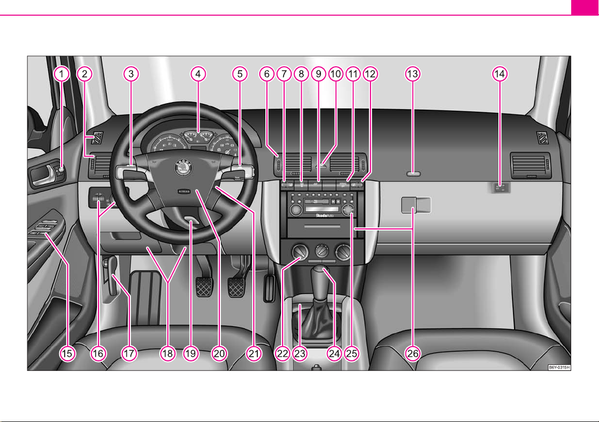
Fig. 1 Certain items of equipment shown in the illustration are only fitted to particular model versions or are optional items of equipment.

Cockpit8
A
A
A
A
A
A
A
A
A
A
A
A
A
A
A
A
A
A
A
A
A
A
A
A
A
A
NKO
A0420book
Page8Friday
March22007
2:18
PM
Cockpit
General view
This general view is designed to help you to quickly become familiar
with the instruments, gauges and controls.
1
Electric exterior mirror adjustment* . . . . . . . . . . . . . . . . . . . . . . . . . .
2
Air outlet vents . . . . . . . . . . . . . . . . . . . . . . . . . . . . . . . . . . . . . . . . . . . . .
3
Lever for the multi-functional switch:
− Turn signal light, headlight and parking light, headlight flasher
− Speed regulating system* . . . . . . . . . . . . . . . . . . . . . . . . . . . . . . . . .
4
Instrument cluster: Instruments and indicator lights . . . . . . . . . . .
5
Lever for the multi-functional switch:
− Multi-functional indicator* . . . . . . . . . . . . . . . . . . . . . . . . . . . . . . .
− Windshield wiper and wash system . . . . . . . . . . . . . . . . . . . . . . . .
6
Air outlet vents . . . . . . . . . . . . . . . . . . . . . . . . . . . . . . . . . . . . . . . . . . . . .
7
Control dial for heating on the driver's seat* . . . . . . . . . . . . . . . . . .
8
Switch for rear window heater . . . . . . . . . . . . . . . . . . . . . . . . . . . . . . .
9
Depending on equipment fitted:
− Switch for the ESP* . . . . . . . . . . . . . . . . . . . . . . . . . . . . . . . . . . . . . . .
− Switch for the TCS* . . . . . . . . . . . . . . . . . . . . . . . . . . . . . . . . . . . . . . .
10
Switch for hazard warning lights . . . . . . . . . . . . . . . . . . . . . . . . . . . . .
11
Indicator light for a switched off front seat passenger airbag* . .
12
Control dial for heating on the front passenger seat* . . . . . . . . . .
13
Front passenger airbag* . . . . . . . . . . . . . . . . . . . . . . . . . . . . . . . . . . . . .
14
Switch for the front seat passenger airbag(s)* . . . . . . . . . . . . . . . . .
15
Switch for:
− Central locking system* . . . . . . . . . . . . . . . . . . . . . . . . . . . . . . . . . .
− Electric power-operated window* . . . . . . . . . . . . . . . . . . . . . . . . .
16
Light switch, control dial for the instrument lighting and control dial
for the headlight beam range regulatiion . . . . . . . . . . . . . . . . . . . . .
17
Bonnet release lever . . . . . . . . . . . . . . . . . . . . . . . . . . . . . . . . . . . . . . . .
125
126
115
111
115
43, 44
151
18
Storage compartments . . . . . . . . . . . . . . . . . . . . . . . . . . . . . . . . . . . . .
19
Lever for adjusting the steering wheel* . . . . . . . . . . . . . . . . . . . . . . .
20
Headlight flasher, driver airbag . . . . . . . . . . . . . . . . . . . . . . . . . . . . . .
21
Ignition lock . . . . . . . . . . . . . . . . . . . . . . . . . . . . . . . . . . . . . . . . . . . . . . .
22
51
76
45
86
9
13
49
76
56
48
Depending on equipment fitted:
− Operating controls for the heating . . . . . . . . . . . . . . . . . . . . . . . .
− Operating controls for the air conditioning system* . . . . . . . .
23
Ashtrays . . . . . . . . . . . . . . . . . . . . . . . . . . . . . . . . . . . . . . . . . . . . . . . . . . .
24
Depending on equipment fitted:
− Gearshift lever (manual gearbox) . . . . . . . . . . . . . . . . . . . . . . . . . .
− Selector lever (automatic gearbox*) . . . . . . . . . . . . . . . . . . . . . . .
25
Radio*
26
Storage compartments . . . . . . . . . . . . . . . . . . . . . . . . . . . . . . . . . . . . .
Note
• Equipment which is marked * is only standard on certain vehicle model
versions or only suppliable as optional equipment for certain models.
• Vehicles with factory-fitted radio, mobile phone, navigation system, CD player
etc. are supplied with separate instructions for operating such equipment.
45
• The arrangement of the controls and switches and the location of some items
on right-hand drive models may differ from that shown in ⇒ page 7, fig. 1. The
symbols on the controls and switches are the same as for left-hand drive models.
56
34
38
69
81
111
82
74
76
67
84
90
69

Instruments and Indicator/Warning Lights
A
A
A3A4A5A
NKO
A0420book
Page9Friday
March22007
2:18
PM
General view of the instrument cluster
Fig. 2 Instrument cluster
1
Engine revolutions counter ⇒ page 10
2
Coolant temperature gauge ⇒ page 10
Fuel gauge ⇒ page 10
Speedometer
− with counter for distance driven ⇒ page 11
− with trip counter for distance driven ⇒ page 11
− with Service Interval Display ⇒ page 11
Digital clock ⇒ page 12 and multi-functional indicator* ⇒ page 13
6
Information display* ⇒ page 16
Instruments and Indicator/Warning Lights 9
When the lights are switched on, the instrument cluster is illuminated.
Using the system Safety Driving Tips General Maintenance Breakdown assistance Technical Data
Instruments and Indicator/Warning Lights10
A
A
A
NKO
A0420book
Page10Friday
March22007
2:18
PM
Engine revolutions counter
The start of the red zone in the revolutions counter ⇒ page 9, fig. 2 indicates the
maximum permissible engine speed for all gears for an engine which has been run
in and operating at a normal temperature. You should shift into the next higher gear
before this red zone is reached, or move the selector lever into position D if your
car is fitted with an automatic gearbox.
One should shift to the next lower gear at the latest when the engine is no longer
running “smoothly”.
Avoid high engine speeds during the running-in period ⇒ page 131.
Caution
The needle of the revolutions counter must on no account move into the red zone
of the scale - risk of engine damage!
For the sake of the environment
Shifting up early helps you save fuel and reduce the operating noise of your
vehicle.
1
Coolant temperature gauge
The coolant temperature gauge ⇒ page 9, fig. 2 operates only when the ignition
is switched on.
In order to avoid any damage to the engine, please pay attention to the following
notes regarding the temperature ranges:
Cold range
If the pointer is in the left-hand area of the scale it means that the engine has not
yet reached its operating temperature. Avoid running at high engine speeds, at full
throttle and at severe engine loads.
2
The operating range
The engine has reached its operating temperature as soon as the pointer moves
into the mid-range of the scale. The pointer may also move further to the right at
high engine loads and high outside temperatures. This is not critical provided the
warning symbol in the instrument cluster does not flash.
If the symbol in the instrument cluster flashes it means that either the coolant
temperature is too high or the coolant level is too low. Please refer to the guidelines ⇒ page 23, “Coolant temperature/coolant level ”.
WARNING
Pay attention to the warning notes ⇒ page 152, “Working in the engine
compartment” before opening the bonnet and inspecting the coolant level.
Caution
Additional headlights and other attached components in front of the fresh air inlet
impair the cooling efficiency of the coolant. There is then a risk of the engine overheating at high outside temperatures and high engine loads!
Fuel gauge
The fuel gauge ⇒ page 9, fig. 2 only operates when the ignition is switched on.
The fuel tank has a capacity of about 45 litres. The warning symbol in the instru-
ment cluster lights up when the pointer reaches the reserve marking. There are now
about 7 litres of fuel remaining in the tank. This symbol is a reminder for you, that
you must refuel.
The following will be displayed in the information display*:
PLEASE REFUEL
A peep sounds as an additional warning signal.
3
Instruments and Indicator/Warning Lights 11
NKO
A0420book
Page11Friday
March22007
2:18
PM
Caution
Never run the fuel tank completely empty! An irregular fuel supply can result in
poor ignition or misfiring. Unburnt fuel may get into the exhaust system and
damage the catalytic converter.
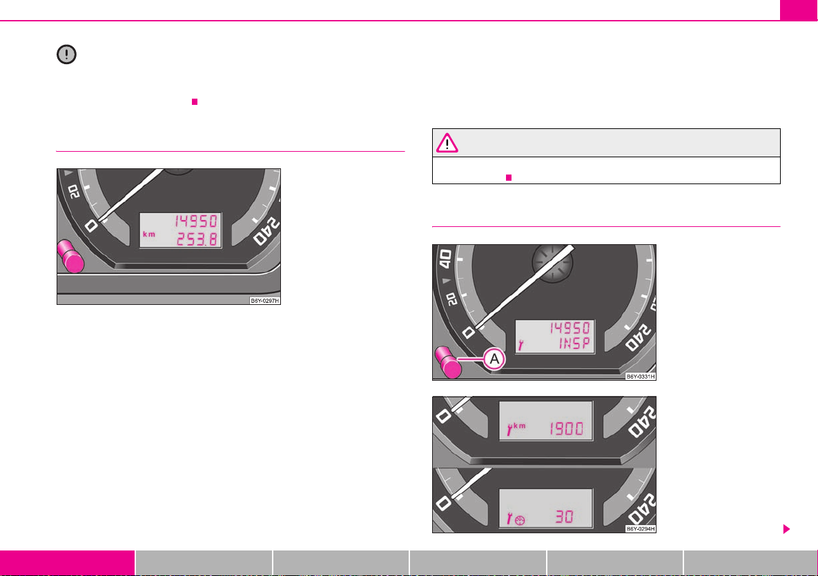
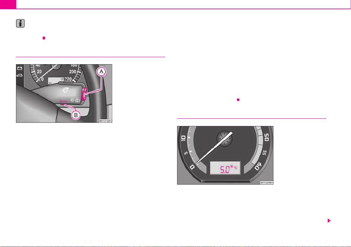
Speedometer with counter for distance driven
Fig. 3 Instrument
cluster: Counter for
distance driven
The distance which you have driven with your vehicle is shown in kilometres (km).
On certain model versions, the readout is shown in “miles”.
Bottom counter (trip counter) for distance driven
The bottom counter indicates the distance which you have driven since this
counter was last reset - in steps of 100 metres or 1/10 of a mile. It can be reset to
zero by pressing the reset button next to the trip counter ⇒ fig. 3.
Top counter for distance driven
The top counter for distance driven indicates the total distance in kilometres or
miles which the vehicle has been driven.
Fault d ispl ay
dEF will appear as a constant text in the display field of the counter for distance
driven if there is a fault in the instrument cluster. Have the fault rectified as soon as
possible by a specialist workshop.
Warning against excessive speeds*
An acoustic warning signal will sound when the vehicle speed exceeds 120 kilometres per hour. The acoustic warning signal will switch off again when the vehicle
speed goes below this speed limit.
This function is only valid for some countries.
WARNING
Never seek to adjust the trip counter for distance driven while driving for
safety reasons!
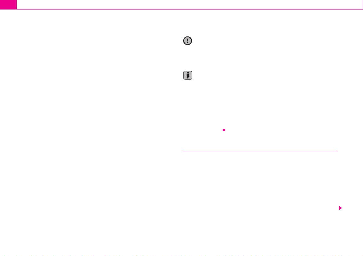
Service Interval Display
Fig. 4 Service Interval
Display: Reset button
Fig. 5 Service Interval
Display
Using the system Safety Driving Tips General Maintenance Breakdown assistance Technical Data
Instruments and Indicator/Warning Lights12
AAA
A
NKO
A0420book
Page12Friday
March22007
2:18
PM
Service Interval Display
A key symbol ⇒ page 11, fig. 5 appears in the counter display for distance driven
about 30 days before reaching the due date for the service. The remaining distance
to be driven will be indicated for 10 seconds next to the key symbol and then the
remaining number of days to the due date for the service inspection.
The following will be displayed in the information display*:
SERVICE DUE IN ... KM OR ... DAYS
The kilometre indicator or the days indicator reduces in steps of 100 km. or days
until the service due date is reached.
The text INSP appears as a flashing key symbol and as soon as the due date for the
service is reached.
The following will be displayed in the information display*:
SERVICE NOW
The display disappears within 20 seconds after switching on the ignition. The trip
counter is also displayed after pressing the reset button of the trip counter for
distance driven (for more than 1 second).
Resetting Service Interval Display
We recommend having this resetting performed by a specialist garage.
The specialist garage:
• resets the memory of the display after the appropriate inspection,
• makes an entry in the Service schedule,
• affix the sticker with the entry of the following service interval to the side of the
dash panel on the driver's side.
It is also possible for you to reset the Service Interval Display with the reset button
⇒ page 11, fig. 4 as follows:
• Press the reset button ⇒ page 11, fig. 4 with the ignition switched off and
and hold it down.
• Switch the ignition on, release the reset button and and turn the reset button
to the right. All counters will be reset to 0.
A
A
It is only possible to reset the Service Interval Display, if a service message or at least
a pre-warning is shown on the display of the instrument cluster.
Caution
We recommend that you do not reset the Service Interval Display yourself otherwise this can result in the service interval display being incorrectly set, which may
also result in problems with operation of your vehicle.
Note
• Never reset the display between service intervals otherwise this may result in
incorrect readouts.
• information is retained in the Service Interval Display also after the battery of
the vehicle is disconnected.
• it is necessa ry to re-code the Service Interval Display if a new instrument cluste r
is installed during repair work. This work is carried out by a specialist garage.
• Please refer to the brochure Service schedule for extensive information about
the service intervals.
Digital clock
A reset button is installed on the left below beside the speedometer for
adjusting the clock ⇒ page 9, fig. 2.
Set hours
– Turn the reset button to the left.
Setting minutes
– Turn the reset button to the right.
Instruments and Indicator/Warning Lights 13
A
NKO
A0420book
Page13Friday
March22007
2:18
PM
WARNING
The clock should not be adjusted while driving for safety reasons but only
when the vehicle is stationary.
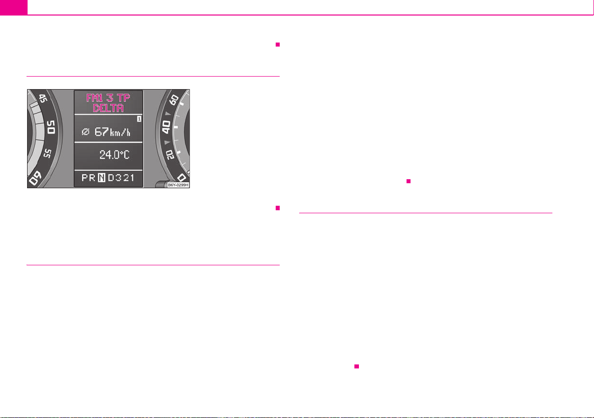
Multi-functional indicator* (onboard computer)
Introduction
The multi-functional indicator appears in the display of the revolutions counter
⇒ fig. 6 or in the information display ⇒ page 16, fig. 9 depending on the equip-
ment fitted to your vehicle.
The multi-functional indicator offers you a range of useful information.
The outside temperature ⇒ page 14
Range ⇒ page 15
Current fuel consumption ⇒ page 15
Average fuel consumption ⇒ page 15
Driving time ⇒ page 15
Distance driven ⇒ page 15
Average speed ⇒ page 16
Note
In certain national versions the displays appear in the Imperial system of
measures.
Memory
Fig. 6 Display in engine
revol utions co unter:
Multi-functional indicator
The multi-functional indicator is equipped with two automatic memories. You can
see the memory which is currently being shown in the display from the negatively
displayed number ⇒ fig. 6.
The data of the single-trip memory (memory 1) is shown if a 1 appears in the
display. A 2 shown in the display means that data relates to the total distance
memory (memory 2).
Switching of the memory takes place when the button ⇒ page 14, fig. 7.
Single-trip memory (memory 1)
The single-trip memory collates the driving information from the moment the ignition is switched on until it is switched off. New data will also flow into the calculation of the current driving information if the trip is continued within 2 hours after
switching off the ignition. The memory will be is automatically erased, on the other
hand, if the trip is interrupted for more than 2 hours.
Total-trip memory (memory 2)
The total distance driven memory gathers data from any number of indvidual journeys up to a total of 100 hours driving or 10 000 kilometres driven. The memory is
deleted when either of these limits is reached and the calculation starts from anew.
The total-trip memory will not, contrary to the single-trip memory, be deleted after
a period of interruption of driving of 2 hours.
B
Using the system Safety Driving Tips General Maintenance Breakdown assistance Technical Data
Instruments and Indicator/Warning Lights14
AAABABA
A
ABA
NKO
A0420book
Page14Friday
March22007
2:18
PM
Note
All information in the memory is erased if the battery of the vehicle is
disconnected.
Using the system
Fig. 7 Multi-functional
indicator: Control
elements
The rocker switch and the button are located in the grip of the
window wiper lever ⇒ fig. 7.
Selecting the memory
– Repeated short-term pressing of the button allows one to select
the individual memories.
Selecting the functions
– Press the rocker switch up or down. This will cause the individual
A
functions of the multi-functional indicator to appear in the display
one after the other.
Setting function to zero
– Select the memory you want.
– Press button for more than 1 second.
B
The following readouts of the selected memory will be set to zero by button :
• average fuel consumption,
• distance driven,
• average speed,
• Driving time.
You can only operate the multi-functional indicator when the ignition is switched
on. After the ignition is switched on, the function displayed is the one which you last
selected before switching off the ignition.
The outside temperature indicator will appear with a snowflake symbol and a
warning signal sounds* when the outside temperature lies between +5°C and -5°C.
The symbol warns the driver of the possible danger of ice on the road. After the
rocker switch is pressed, the function displays the one which you last selected
before switching off the ignition.
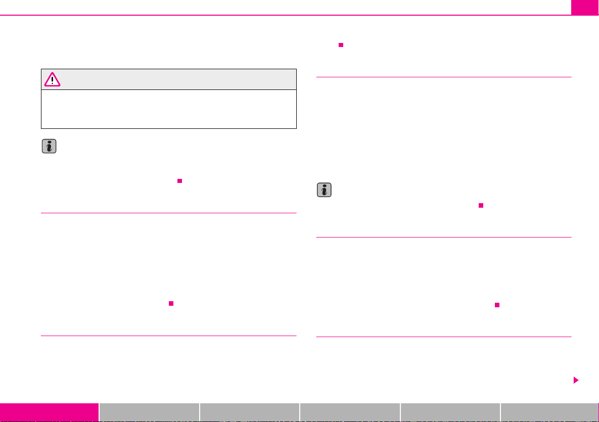
Outside temperature
The outside temperature appears in the display when the ignition is switched on.
The correct outside temperature will be indicated with a delay of 5 minutes. If the
vehicle is stationary (or driven at a very low speed) the temperature indicated may
be slightly higher than the actual outside temperature because of heat radiated by
the engine.
A
Fig. 8 Multi-functional
indicator: the outside
temperature
Instruments and Indicator/Warning Lights 15
A
A
A
NKO
A0420book
Page15Friday
March22007
2:18
PM
The outside temperature indicator will appear with a snowflake symbol (warning
signal for ice on the road) ⇒ page 14, fig. 8 and a warning signal sounds* when the
outside temperature lies between +5°C and -5°C.
WARNING
Do not only rely upon the information given on the outside temperature
display that there is no ice on the road. Ple ase note tha t black ice may also be
present on the road surface even at temperatures around +5°C - warning,
drive with care!
Note
The outside temperature is not indicating when showing navigation data (guidance
to the destination). It must be called up over the menu (valid for vehicles which
have a navigation and information display).
Range
The estimated range in kilometres is shown on the display. It indicates the distance
you can still drive with your vehicle based on t he present level of fuel in the tank for
the same style of driving. The readout is shown in steps of 5 km.
The fuel consumption for the last 50 km is taken as a basis for calculating the range.
If you drive in a more economical manner from this moment on, the range will be
increased accordingly.
You first drive 50 km if the readout is reset (after disconnecting the battery) before
a new readout for the range is displayed.
The display appears in litres/hour if the vehicle is stationary or driving at a low
speed.
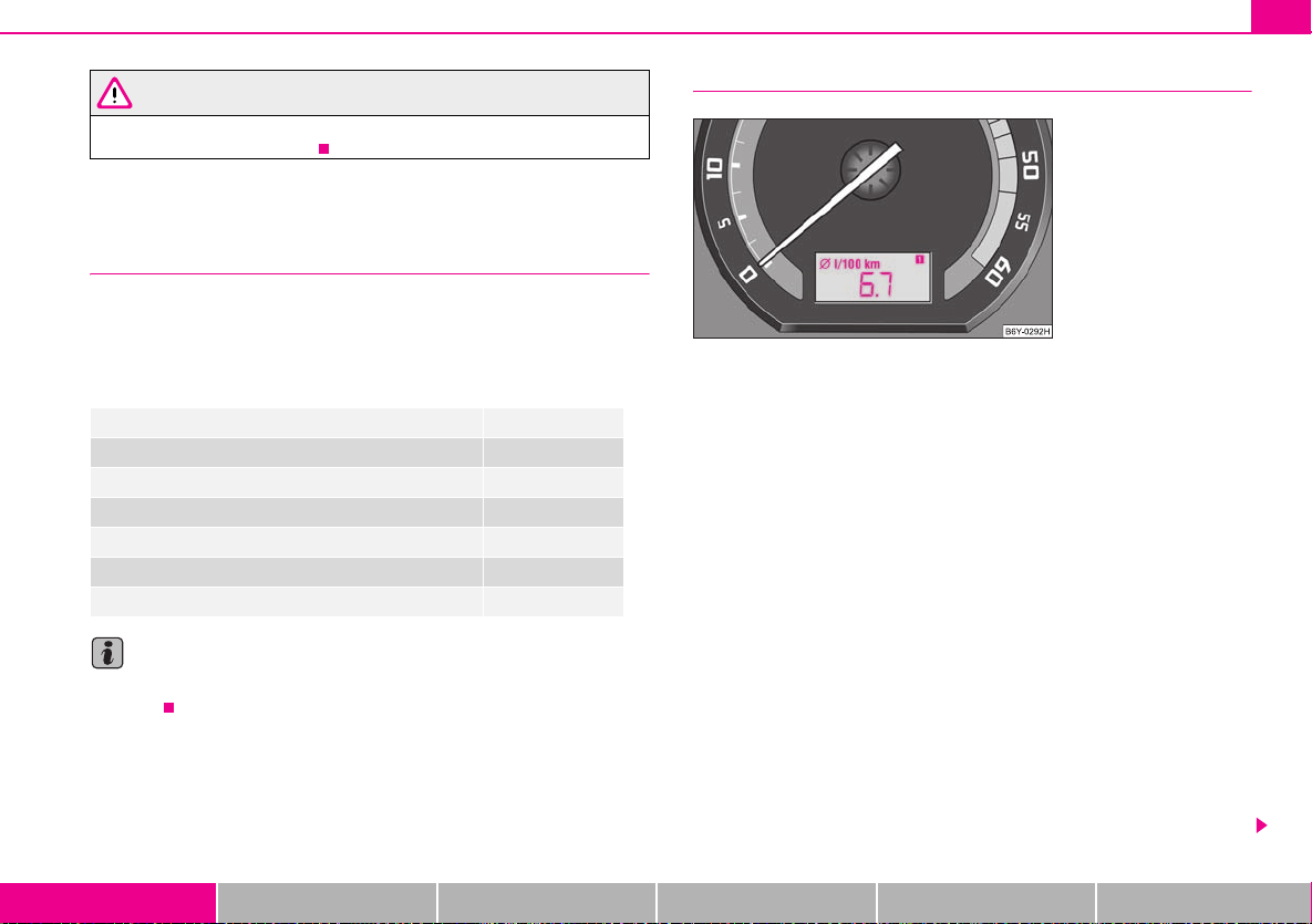
Average fuel consumption
The average fuel consumption since the memory was last erased is shown in the
display in litres/100 km ⇒ page 13. This information can help you to adapt your
style of driving to the fuel consumption you wish to achieve.
If you wish to determine the average fuel consumption over a certain period of time
you must first erase the memory at the start of the new measurement using the
B
button ⇒ page 14, fig. 7. A zero appears in the display for the first 300 m you
drive after erasing the memory.
The indicated value will be updated every 5 seconds while you are driving.
Note
The amount of fuel consumed will not be indicated.
Driving time
The driving time which has elapsed since the memory was last erased, appears in
the display ⇒ page 13. If you wish to calculate the driving time from a particular
time of day you must first erase the memory at this moment in time by pressing the
B
button ⇒ page 14, fig. 7.
The maximum time indicated in both switch positions is 99 hours and 59 minutes.
The indicator is set back to null if this period is exceeded.
Current fuel consumption
The current fuel consumption level is shown in the display in litres/100 km. This
information can help you to adapt your style of driving to the fuel consumption you
wish to achieve.
Using the system Safety Driving Tips General Maintenance Breakdown assistance Technical Data
Distance driven
The distance driven since the memory was last erased appears in the display
⇒ page 13. If you wish to calculate the distance driven from a particular time of day
you must first erase the memory at this moment in time by pressing the button
⇒ page 14, fig. 7.
B
Instruments and Indicator/Warning Lights16
A
NKO
A0420book
Page16Friday
March22007
2:18
PM
The maximum distance indicated in both switch positions i s 9999 km. The indicator
is set back to null if this period is exceeded.
Average speed
The average speed since the memory was last erased is shown in the display in
km/hour ⇒ page 13. If you wish to determine the average speed over a certain
period of time you must first erase the memory at the start of the new measurement using the button ⇒ page 14, fig. 7.
A zero appears in the display for the first 100 m you drive after erasing the
memory.
B
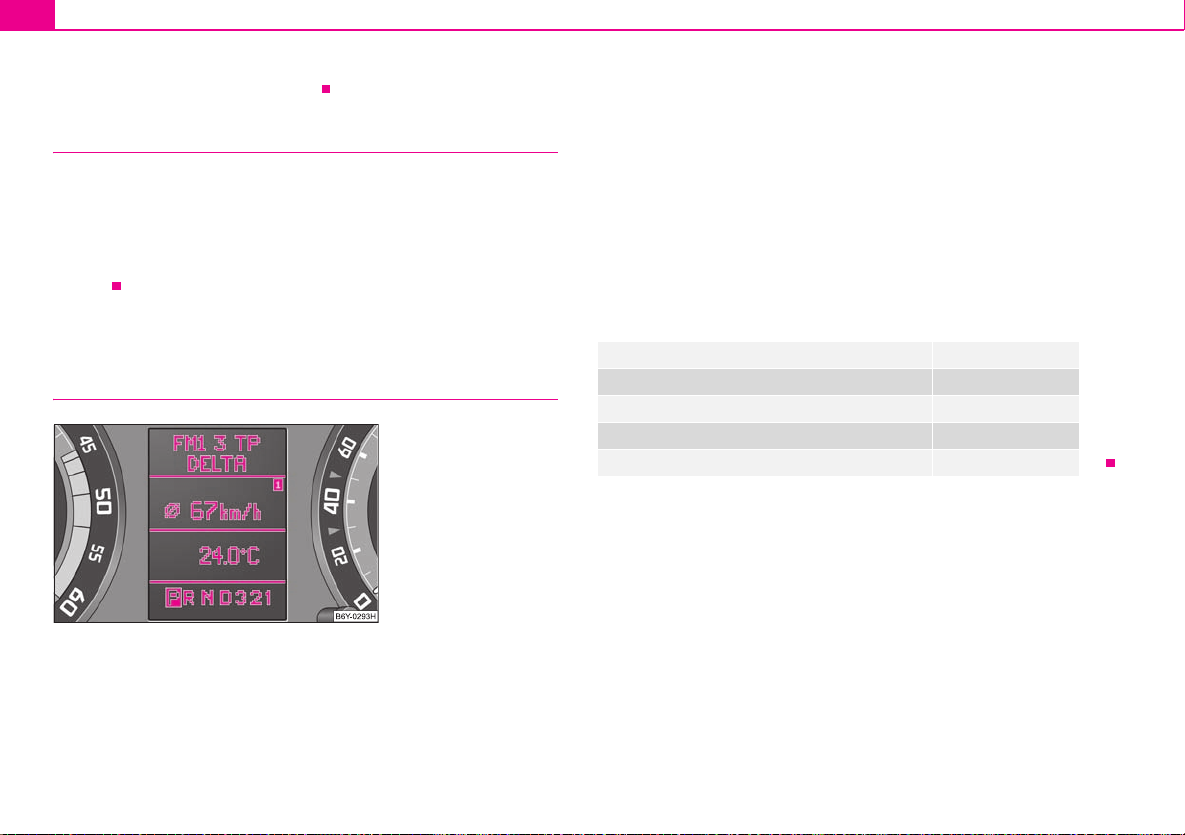
Information display*
Introduction
Fig. 9 Instrument
cluster: Information
display
Certain functions and operating conditions are always being checked on the
vehicle when the ignition is switched on and also while driving.
Functional faults, if required repair work and other information are indicated by red
symbols ⇒ page 19 and yellow symbols ⇒ page 19.
Lighting up of these symbols is combined with an acoustic warning signal.
Information and texts giving warnings are also shown in the display ⇒ page 20.
The display of text is possible in the following languages:
Czech, English, German, French, Italian, Spanish, Portuguese.
You can have the relevant language set by a specialist garage.
The following information can be shown in the display (depending on the equipment installed on the vehicle):
Menu ⇒ page 17
Door, tailgate and bonnet ajar warning ⇒ page 17
Radio display ⇒ page 18
Service Interval Display ⇒ page 11
Selector lever position for an automatic gearbox ⇒ page 90
The information display provides you with information in a convenient way
concerning the current operating state of your vehicle. The information system
also provides you with data (depending on the equipment installed in the vehicle)
relating to the radio, multi-functional indicator, navigation system and automatic
gearbox.
Instruments and Indicator/Warning Lights 17
A
AAABA
A
NKO
A0420book
Page17Friday
March22007
2:18
PM
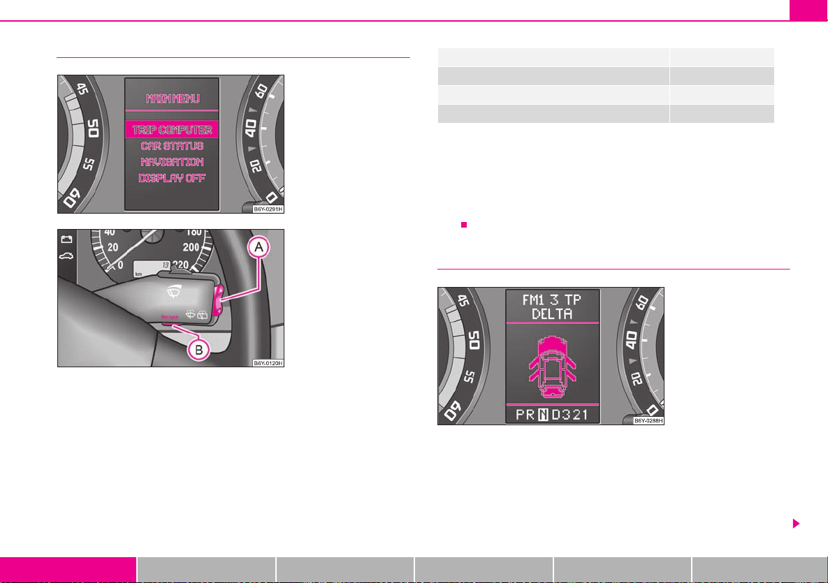
Menu
Fig. 10 Information
display: Menu
Fig. 11 Information
display: Control
elements
– You can activate the menu by pressing the rocker switch ⇒ fig. 11
A
for more than 1 second.
– You can select the menu through the rocker switch . The selected
information is displayed after pressing the button for a short time
or after releasing the rocker switch (after about 4 seconds).
You can select the following information (depending on the equipment installed on
the vehicle):
A
TRIP COMPUTER (AUTO COMPUTER) ⇒ page 13
CAR STATUS ⇒ page 18
NAVIGATION ⇒ page 20
DISPLAY OFF
After selecting the menu DISPLAY OFF the display is switched off. Press rocker
A
switch for at least 1 second to switch the display on again.
The Information CAR STATUSflashes in the menu if there is something which is not
in proper order on the vehicle (e.g. warning of a low fuel level). The first warning will
be displayed after switching over to CAR STATUS. You can then display other operating conditions afterwards using the switch-over function (such as water level
low).
Door, tailgate and bonnet ajar warning
Fig. 12 Information
display: Door warning
The door, tailgate compartment door and bonnet ajar warning lights up when at
least one of the three items door, tailgate or bonnet are not closed when the ignition is turned on. The symbol indicates which door is still open or whether the tailgate or bonnet is not closed ⇒ fig. 12.
The symbol goes out as soon as the doors, tailgate and bonnet are completely
closed.
Using the system Safety Driving Tips General Maintenance Breakdown assistance Technical Data
Instruments and Indicator/Warning Lights18
A
A
NKO
A0420book
Page18Friday
March22007
2:18
PM
As an additional warning signal, a 3 time peep sounds if the car is driven at a speed
of mor e th an 6 km/ hou r an d if the doo r or the lug gag e c omp art men t do or i s op en.
Radio display
Fig. 13 Information
display: Radio display
These displays appear in addition to the normal information in the radio display.
Auto Check Control
Car state
The Auto Check Control carries out a check of certain functions and vehicle components. The check is performed constantly when the ignition is switched on, both
when the vehicle is stationary, as well as when driving.
Operational faults, urgent repairs, service work or other information appear in the
display of the instrument cluster. The displays are shown with a red or yellow light
symbol depending on the priority of the message.
The red symbols indicate danger (priority 1) while the yellow symbols indicate a
warning (priortity 2). Information for the driver may also appear in addition to the
symbols ⇒ page 20.
Investigate the displayed faults as soon as possible. If several operational faults exist
at the same time, the symbols will appear one after the other and are each visible
for about 2 seconds.
The error messages are faded out after 10 seconds or by actuating the rocker switch
A
⇒ page 17, fig. 11 and are stored under the information CAR STATUS.
There is at least one error message to be read when the term CAR STATUS is
flashing in the main menu. The display will show STATUS 1/2 (for example) if a
number of error messages are present. This display indicates that the first of a total
of two error messages should be displayed.
Actuate the rocker switch , to call up the individual error messages.
If a fault occurs, a warning signal will also sound in addition to the symbol and text
in the display:
A
• Priority 1 - three warning signals,
• Priority 2 - one warning signal.
Operational check of the automatic gearbox
When the ignition is switched on, the Auto Check Control automatically carries out
an operational check. The following text will appear first in the display if the selector
lever is the position P or N:
P LOCKED (P locked)
or
N LOCKED (N locked)
You must depress the brake pedal first and press the Shiftlock button at the same
time in order to move the selector lever out of these positions.
The text will disappear once you select a drive position (R, D etc.), and the Auto
Check Control function is displayed.
If the Auto Check Control detects faults, these will be displayed about 15 seconds
after starting the engine in place of the text shown above. A warning signal sounds
at the same time.
Instruments and Indicator/Warning Lights 19
NKO
A0420book
Page19Friday
March22007
2:18
PM
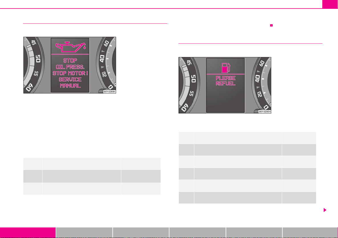
Red symbols
A red symbol signals danger.
Fig. 14 Information
display: Oil pressure is
low
Proceed as follows if a red symbol is displayed:
– Stop the vehicle.
– Switch the engine off.
– Investigate the function indicated.
– Obtain professional assistance.
Meaning of the red symbols:
Faults in the brake surface ⇒ page 27
Coolant level too low/coolant temperature
too high
Engine oil pressure too low ⇒ page 24
Three successive warning signals will sound if a red symbol appears. The symbol
continues flashing until the fault is rectified.
⇒ page 23
If several operational faults of priority 1 exist, the symbols appear one after the
other and are each illuminated for about 2 seconds.
Yellow symbols
A yellow symbol signals a warning.
Fig. 15 Information
display: Fuel level low
The meaning of the yellow symbols:
Fuel level low ⇒ page 24
Check engine oil level, engine oil sensor faulty ⇒ page 24
Brake pad worn ⇒ page 25
Washer fluid level low ⇒ page 25
Light bulb defect ⇒ page 25
Light bulb in the brake light defect ⇒ page 25
One warning signal will sound if a yellow symbol appears.
Using the system Safety Driving Tips General Maintenance Breakdown assistance Technical Data
Instruments and Indicator/Warning Lights20
NKO
A0420book
Page20Friday
March22007
2:18
PM
If several operational faults of priority 2 exist, the symbols appear one after the
other and are each illuminated for about 2 seconds.
Check the relevant function as soon as possible.
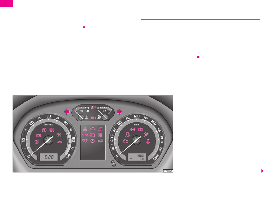
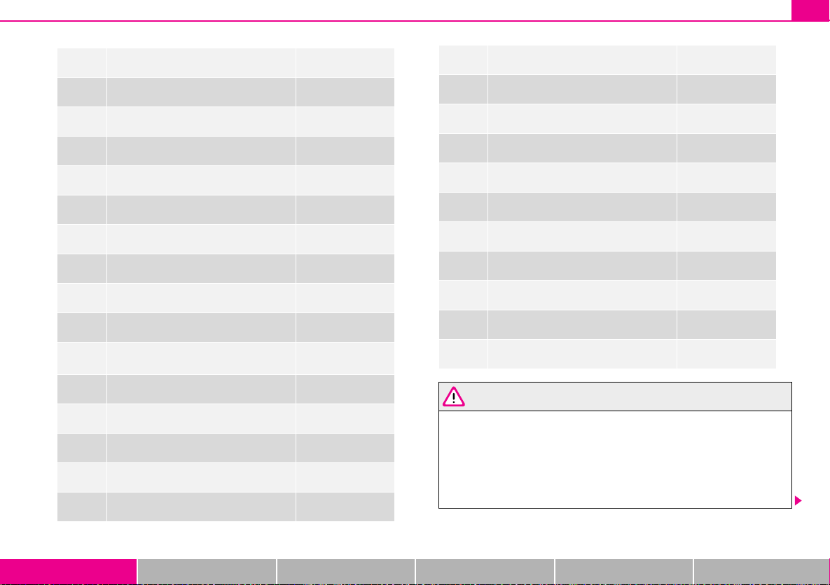
Warning lights
Overview
The warning lights indicate certain functions or faults.
Navigation system*
The controls for the navigation system, radio, CD player are located in the centre
console on both sides of the monitor screen. Navigation data is also shown in the
information display of the instrument cluster.
Information and warning texts are displayed preferentially when the navigation
system is switched on.
Operation of the navigation system is described in separate operating instructions
to be found in the on-board literature.
Fig. 16 Instrument cluster with warning lights
NKO
A0420book
Page21Friday
March22007
2:18
PM
Turn signal lights (to the left) ⇒ page 22
Turn signal lights (to the right) ⇒ page 22
Main beam ⇒ page 22
Low beam ⇒ page 22
Rear fog light ⇒ page 22
Dynamo ⇒ page 22
Fog lights* ⇒ page 22
Power steering* ⇒ page 22
EPC fault light (petrol engine) ⇒ page 23
Glow plug system (diesel engine) ⇒ page 23
Turn signal system for vehicles towing a
trailer*
Coolant temperature/coolant level ⇒ page 23
Electronic immobiliser ⇒ page 24
Fuel reserve ⇒ page 24
Engine oil ⇒ page 24
Brake pad wear* ⇒ page 25
⇒ page 23
Instruments and Indicator/Warning Lights 21
Bulbs* ⇒ page 25
Open door* ⇒ page 25
Fluid level in windshield washer system* ⇒ page 25
Boot lid* ⇒ page 25
Control system for exhaust ⇒ page 26
Tra cti on c ont rol sys tem (TC S)* ⇒ page 26
Electronic stability programme (ESP)* ⇒ page 26
Antilock brake system (ABS)* ⇒ page 26
Brake system ⇒ page 27
Airbag system ⇒ page 27
Seat belt warning light* ⇒ page 28
WARNING
• If you do n ot pay attention to the warning lights coming on and the corre-
sponding descriptions and warning notes, this may result in severe body
injuries or major vehicle damage.
• The engine compartment of your car is a hazardous area. There is a risk
of injuries, scalding, accidents and fire when working in the engine
compartment, e.g. inspecting and replenishing oil and other fluids. It is also
essential to observe all warnings ⇒ page 152.
Using the system Safety Driving Tips General Maintenance Breakdown assistance Technical Data
Instruments and Indicator/Warning Lights22
NKO
A0420book
Page22Friday
March22007
2:18
PM
Note
• Arrangement of the indicator lights depends on the model and model version.
The symbols shown in the following functional description are to be found as indicator lights in the instrument cluster.
• Operational faults are shown in the instrument cluster as red symbols (priority
1 - danger) or yellow symbols (priority 2 - warning).
Turn signal system
Either the left or right indicator light flashes depending on the position of the
turn signal lever.
The indicator light flashes at twice its normal rate if a turn signal light fails. This does
not apply when towing a trailer.
Switching off the hazard warning light system is switched on will cause all of the
turn signal lights as well as both indicator lights to flash.
Further information about the turn signal system ⇒ page 45.
Main beam
The indicator light comes on when the main beam is selected or also when the
headlight flasher is operated.
Further information about the main beam ⇒ page 45.
Low beam
The indicator light comes on when low beam is selected ⇒ page 43.
Rear fog light
Alternator
The warning light comes on after the ignition has been switched on. It should go
out after the engine has started.
If the warning light does not come on after the ignition is switched on, drive to
the nearest specialist garage.
If the warning light does not go out after the engine has started, or comes on when
driving, drive to the nearest specialist garage. The vehicle batter y will be discharged
in this case so switch off all non-essential electrical components.
The following text will be displayed in the information display*:
ALTERNATOR WORKSHOP! (ALTERNATOR WORKSHOP!)
Caution
If the warning light comes on when driving and in addition the warning light
(cooling system fault) also comes on in display, you must then stop the car immediately and switch the engine off - risk of engine damage!
Fog lights*
The warning light comes on when the fog lights are operating ⇒ page 44.
Power steering*
The warning light comes on for approx. 2 seconds after the ignition is switched
on. There is a fault in the electronics for the power-assisted steering if the warning
light lights up while driving or does not go out 2 seconds after switching on the ignition. Contact a specialist garage to obtain assistance.
The warning light does not come on when there is a lack of oil.
Further information ⇒ page 130, “Power steering*”.
The warning light comes on when the rear fog lights are operating ⇒ page 44.
Instruments and Indicator/Warning Lights 23
NKO
A0420book
Page23Friday
March22007
2:18
PM
Note
There is no power-assisted steering support when the vehicle is being towed
without the engine running or when the power-assisted steering is defect. The
vehicle is fully steerable however. There is simply increased force required to turn
the steering wheel.
EPC fault light (petrol engine)
The (Electronic Power Control) warning light comes on for a few seconds when
the ignition is switched on.
There is a system fault in the engine control system if the warning light does not
go out or comes on or flashes while driving. The engine management system
selects an emergency programme which enables you to drive to the nearest
specialist garage by adopting a gentle style of driving.
The following text will be displayed in the information display*:
ENGINE WORKSHOP! (ENGINE FAULT - WORKSHOP!)
Glow plug system (diesel engine)
The indicator light lights up for a cold engine when switching on the ignition
(pre-heat position) 2 ⇒ page 82. Star t the engine just as soon as the indicator light
goes out.
The glow plug indicator light will come on for about 1 second if the engine is at a
normal operating temperature or if the outside temperature is above +5°C. This
means that you can start the engine right away.
There is a fault in the glow plug system if the indicator light does not come on
at all or lights up continuously. Contact a specialist garage as soon as possible to
obtain professional assistance.
There is a system fault in the engine control system if the warning light has
started to flash while driving. The engine management system selects an emergency programme which enables you to drive to the nearest specialist garage by
adopting a gentle style of driving.
The following text will be displayed in the information display*:
ENGINE WORKSHOP! (ENGINE FAULT - WORKSHOP!)
Turn signal system for vehicles towing a trailer*
The indicator light on vehicles towing a trailer flashes together with the respective indicator light for the turn signal system.
The indicator light does not flash if a turn signal light on the trailer or on the
vehicle is not operating.
Coolant temperature/coolant level
The warning light comes on for a few seconds 1) when the ignition is switched on.
The coolant temperature is too high or the coolant level too low if the warning light
does not go out after the engine is started or flashes while driving.
3 peeps sound as an additional warning signal.
In this case stop and switch the engine off and check the coolant level; top up the
coolant as necessary.
Do not continue your journey if for some reason it is not possible under the
conditions prevailing to top up with coolant. Keep the engine switched off and
obtain professional assistance from a specialist garage, otherwise it could lead to
severe engine damage.
If the coolant is within the specified range, the increased temperature may be
caused by an operating problem at the coolant fan. Check the fuse for the coolant
fan, replace it if necessary ⇒ page 188, “Fuse assignment at battery”.
Do not continue driving if the warning light doe s not go off although the fluid is at
the correct level and also the fuse of the fan is in proper order. Contact a specialist
garage to obtain assistance.
1)
The warning light on vehicles fitted with information display does not come on after
switching the ignition on, but only if the coolant temperature is too high or the coolant level
is too low.
Using the system Safety Driving Tips General Maintenance Breakdown assistance Technical Data
Instruments and Indicator/Warning Lights24
NKO
A0420book
Page24Friday
March22007
2:18
PM
Please also refer to the additional instructions ⇒ page 156, “Cooling system”.
The following text will be displayed in the information display*:
STOP CHECK COOLANT SERVICE MANUAL (STOP! CHECK COOLANT
OWNER'S MANUAL)
WARNING
• If you must stop for technical reasons, then park the vehicle at a safe
distance from the traffic and switch off the engine and switch on the hazard
warning light system ⇒ page 45.
• Take care when opening the coolant expansion bottle. If the engine is hot,
the cooling system is pressurized - risk of scalding. It is best to allow the
engine to cool down before removing the cap.
• Do not touch the coolant fan! The coolant fan may switch on automati-
cally even if the ignition is off.
Electronic immobiliser
Data is compared between the ignition key and the control unit when switching on
the ignition. The indicator light
authorisation is confirmed.
The warning light will start flashing continuously if a non-authorised ignition key
(for example the wrong ignition key) has been used. The engine cannot be started
⇒ page 30.
It is only possible to start the engine of the vehicle with a Genuine Škoda key with
the matching code.
Fuel reserve
The warning light comes on, if the fuel level is still about 7 litres.
A peep sounds as an additional warning signal.
will light up for a few seconds when ignition key
The following text will be displayed in the information display*:
PLEASE REFUEL
Engine oil
The warning light lights up red (low oil pressure)
The warning light comes on for a few seconds 2) when the ignition is switched on.
Stop the vehicle and switch the engine off if the warning light does not go off
after the engine has started or flashes while driving. Check the oil level and top up
with oil as necessary ⇒ page 155.
3 peeps sound as an additional warning signal.
Do not continue your journey if for some reason it is not possible under the
conditions prevailing to top up with oil. Keep the engine switched off and obtain
professional assistance from a specialist garage, otherwise it could lead to severe
engine damage.
Do not drive any further if the warning light flashes even if the oil is at the correct
level. Do not run the engine not at idling speed either. Contact the nearest specialist
garage to obtain professional assistance.
The following text will be displayed in the information display*:
STOP! OIL PRESS. STOP MOTOR! SERVICE MANUAL (STOP! OIL PRESSURE
STOP ENGINE! OWNER'S MANUAL)
The warning light lights up yellow* (oil quantity too low)
If the warning light lights up yellow, the quantity of oil in the engine is probably too
low. Check as soon as possible the oil level or top up ⇒ page 155 with engine oil.
A peep sounds as an additional warning signal.
The following text will be displayed in the information display*:
CHECK OIL LEVEL
2)
The warning light on vehicles fitted with information display does not come on after
switching the ignition on, but only if a fault exists or the engine oil level is too low.
Instruments and Indicator/Warning Lights 25
NKO
A0420book
Page25Friday
March22007
2:18
PM
The warning light will go out if the bonnet is left open for more than 30 seconds. If
no engine oil has been replenished, the warning light will come on again after
driving about 100 km.
The warning light flashes yellow* (engine oil level sensor faulty)
A fault on the engine oil level sensor is indicated additionally by an audible signal
and the warning light coming on several times after the ignition has been switched
on.
In this case have the engine inspected without delay by a specialist garage.
The following text will be displayed in the information display*:
OIL SENSOR WORKSHOP! (OIL SENSOR WORKSHOP)
WARNING
• If you must stop for technical reasons, then park the vehicle at a safe
distance from the traffic and switch off the engine and switch on the hazard
warning light system ⇒ page 45.
• The red oil pressure light is not an oil level indicator! One should
therefore check the oil level at regular intervals, preferably after every refueling stop.
Thickness of the brake pads*
If the warning light comes on, contact a specialist garage immediately and have
the brake pads on all of the wheels inspected.
A peep sounds as an additional warning signal.
The following text will be displayed in the information display*:
CHECK BRAKE PADS
Light bulbs*
The warning light comes on if a light bulb is damaged:
• brakes applied (brake light),
• in lighting (low beam and/or rear light).
A peep sounds as an additional warning signal.
The following text will be displayed in the information display*:
LIGHTS FAILURE
or
BRAKE LIGHTS FAILURE
Open door*
The warning light comes on, if one or several doors are opened.
The warning light on vehicles fitted with information display comes on when
switching the ignition off. The warning light goes out about 15 seconds after locking
the vehicle.
The warning light on vehicles fitted with information display goes out after
switching the ignition off.
Windshield washer fluid level*
The warning light comes on when the ignition is switched on if there is insufficient fluid in the windshield washer system. Top up with liquid ⇒ page 164.
A peep sounds as an additional warning signal.
The following text will be displayed in the information display*:
TOP U P WASH FLUID
Luggage compartment door*
The warning light comes on when the ignition is switched on if the luggage
compartment door is open.
3 peeps sound as an additional warning signal.
Using the system Safety Driving Tips General Maintenance Breakdown assistance Technical Data

Instruments and Indicator/Warning Lights26
NKO
A0420book
Page26Friday
March22007
2:18
PM
Control system for exhaust
The warning light comes on after the ignition has been switched on.
If the warning light does not go out after starting the engine or it lights up or flashes
when driving, a fault exists in an exhaust relevant component. The engine management system selects an emergency programme which enables you to drive to the
nearest specialist garage by adopting a gentle style of driving.
The following text will be displayed in the information display*:
EMISSIONS WORKSHOP! (EMISSIONS WORKSHOP)!
Traction control system (TCS) *
The warning light comes on for a few seconds when the ignition is switched on.
The warning light comes on when driving when a control cycle is activated.
The warning light will come on and remains on if the TCS is switched off or if there
is a fault in the system.
The fact that the TCS system operates together with the ABS means that the TCS
warning light will also come on if the ABS system is not operating properly.
Further information about the TCS ⇒ page 126, “Traction control system (TCS)*”.
Electronic stability programme (ESP)*
The warning light comes on for a few seconds when the ignition is switched on.
Components of the ESP system also include the Traction Control System (TCS),
Electronic Differential Lock (EDL), and the Antilock Brake System ABS (ABS).
The warning light comes on when driving when a control cycle is activated.
The warning light will come on and remains on if the ESP is switched off or if there
is a fault in the system.
The fact that the ESP system operates together with the ABS means that the ESP
warning light will also come on if the ABS system is not operating properly.
Further information on the ESP ⇒ page 125, “Electronic stability programme
(ESP)*”.
Electronic Differential Lock (EDL)*
The EDL is a part of the ESP. A fault in the EDL is indicated by the ESP warning light
in the instrument cluster. Have the vehicle inspected immediately by your
specialist garage. Further information on the EDL ⇒ page 127.
Antilock brake system (ABS)*
The warning light shows the functionality of the ABS.
The warning light comes on for a few seconds after the ignition has been switched
on or when starting the engine. The w arning light goes out after an automatic check
sequence has been completed.
A fault in the ABS
The system is not functioning properly if the ABS warning light does not go out
within a few seconds after switching on the ignition, does not light up at all or lights
up while driving. The vehicle will only be braked by the normal brake system. Visit
a specialist garage as quickly as possible and adjust your style of driving in the
meantime since you will not know how great the damage is.
Three additional warning tones will sound if there is a major fault in the ABS.
Further information about ABS ⇒ page 129, “Antilock brake system (ABS)*”.
A fault in the entire brake system
If the ABS warning light comes on together with the brake system warning light
(handbrake must be released), there is a fault not only in the ABS but also in
another part of the brake system ⇒ .
The following text will be displayed in the information display*:
STOP BRAKE FAULT SERVICE MANUAL (STOP! BRAKE FAULT OWNER'S
MANUAL)
Instruments and Indicator/Warning Lights 27
NKO
A0420book
Page27Friday
March22007
2:18
PM
WARNING
• If the brake system warning light comes on together with the ABS
warning light stop the vehicle immediately and check the brake fluid
level in the reservoir ⇒ page 159, “Brake fluid”. If the fluid level has dropped
below the MIN marking, do not drive any further - risk of accident! Contact
a Škoda dealer to obtain professional assistance.
• Pay attention to the following instructions ⇒ page 152, “Working in the
engine compartment” before checking the brake fluid level and opening the
bonnet.
• If the brake fluid is at the correct level, the ABS control function has
failed. The rear wheels may then block very rapidly when braking. In certain
circumstances, this can result in the rear end of the car breaking away - risk
of skidding! Drive carefully to the nearest specialist garage and have the
fault rectified.
Brake system
The warning light flashes or comes on if the brake fluid level is too low, if there
is a fault in the ABS or if the handbrake is applied.
If the warning light flashes (handbrake is not applied), stop and check the brake
fluid level ⇒ .
The following text will be displayed in the information display*:
STOP BRAKE FLUID OWNER'S MANUAL
If there is a fault in the ABS which also influences the function of the normal brake
system (e.g. distribution of brake pressure), the ABS warning light comes on
together with the brake system warning light . Be aware that not only the ABS but
also another part of th brake system is defective ⇒ .
3 peeps sound as an additional warning signal.
One should get used to high pedal forces, long braking distances and long free play
of the brake pedal when driving to the next specialist garage.
The following text will be displayed in the information display*:
STOP BRAKE FAULT OWNER'S MANUAL
For further information on the brake system ⇒ page 128, “Brakes”.
Handbrake applied
The warning light also comes on if the handbrake is applied. An audible warning
is also given if you drive the vehicle for at least 3 seconds at a speed of more than 6
km/h.
The following text will be displayed in the information display*:
HANDBRAKE ON
WARNING
• Pay attention to the following instructions ⇒ page 152, “Working in the
engine compartment” before checking the brake fluid level and opening the
bonnet.
• If the brake system warning light does not go out a few seconds after
switching on the ignition or comes on when driving, stop immediately and
check the brake fluid in the reservoir ⇒ page 159, “Brake fluid”. If the fluid
level has dropped below the MIN marking, do not drive any further - risk of
accident! Contact a Škoda dealer to obtain professional assistance.
Airbag system
Monitoring the airbag system
The warning light
There is a fault in the system if the warning light does not go out or comes on or
flashes while driving ⇒ . This also applies if the warning light does not come on
when the ignition is switched on.
The following text will be displayed in the information display*:
AIRBAG FAULT
comes on for a few seconds when the ignition is switched on.
Using the system Safety Driving Tips General Maintenance Breakdown assistance Technical Data
Instruments and Indicator/Warning Lights28
NKO
A0420book
Page28Friday
March22007
2:18
PM
The functionality of the airbag system is also monitored electronically, when one
airbag has been switched off
The passenger front airbag and also possibly the passenger side airbag which
have been switched off using the vehicle system tester:
• The warning light lights up for 3 seconds after switching on the ignition and
then flashes for 12 seconds afterwards in 2 second intervals.
Front or side airbags for passenger which have been switched off using the
switch (for switching off airbags)* in the storage compartment on the front
passenger side:
• The warning light comes on for 3 seconds after the ignition has been
switched on.
• Switching off airbags is indicated in the middle of the dash panel by the lighting
up of the indicator light (airbag switched off) ⇒ page 115.
WARNING
Have the airbag system checked immediately by a specialist garage if a fault
exists. Otherwise, there is a risk of the airbag not being activated in the event
of an accident.
Note
Further information about switching off airbags ⇒ page 114, “Deactivating an
airbag”.
Seat belt warning light*
The warning light comes on for a few seconds after the ignition is switched on as
a reminder to fasten the seat belt.
If you do not fasten the seat belt, a long warning signal sounds for 6 seconds.
The following text will be displayed in the information display*:
FASTEN SEATBELT
For further information on the seat belts ⇒ page 103, “Why seat belts?”.
 Loading...