

Page 1

SIMPLY CLEVER
ŠKODA Citigo
Owner's Manual
Page 2

Layout of this Owner's Manual (explanations)
This Owner's Manual has been systematically designed to make it easy for you
to search for and obtain the information you require.
Chapters, table of contents and subject index
The text of the Owner's manual is divided into relatively short sections which
are combined into easy-to-read chapters. The chapter you are reading at any
particular moment is always specified on the bottom right of the page.
The Table of contents is arranged according to the chapters and the detailed
Subject index at the end of the Owner's Manual helps you to rapidly find the
information you are looking for.
Direction indications
All direction indications such as “left”, “right”, “front”, “rear” relate to the direction
of travel of the vehicle.
Units of measurement
All values are expressed in metric units.
Explanation of symbols
Denotes a reference to a section with important information and safety
advice in a chapter.
Denotes the continuation of a section on the next page.
Indicates situations where the vehicle must be stopped as soon as
possible.
® Denotes a registered trademark.
Notes
WARNING
The most important notes are marked with the heading WARNING. These
WARNING notes draw your attention to a serious risk of accident or injury.
For the sake of the environment
An Environmental note draws your attention to environmental protection aspects. This is where you will, for example, find tips aimed at reducing your fuel
consumption.
Note
A normal Note draws your attention to important information about the operation of your vehicle.
CAUTION
A Caution note draws your attention to the possibility of damage to your vehicle
(e.g. damage to gearbox), or points out general risks of an accident.
1ST012720AG
Page 3

Preface
You have opted for a ŠKODA – our sincere thanks for your confidence in us.
You have received a vehicle with the latest technology and range of amenities. Please read this Owner's Manual carefully, because the operation in accordance with these instructions is a prerequisite for
proper use of the vehicle.
Observe the national legal requirements when using your vehicle.
If you have any questions about your vehicle, please contact a ŠKODA Partner.
We wish you much pleasure with your ŠKODA and pleasant motoring at all times.
Your ŠKODA AUTO a.s. (hereinafter referred to only as ŠKODA or manufacturer)
1ST012720AG
Page 4

Terms used
The on-board literature contains the following terms relating to the service
work for your vehicle.
“Specialist”
“ŠKODA service partner”
“ŠKODA partner”
Owner's Manual
These operating instructions apply to all body variants of the vehicle and all
related models.
This owner's manual describes all possible equipment variants without identifying them as special equipment, model variants or market-dependent equipment.
Consequently, this vehicle does not need to contain all of the equipment
components described in this owner's manual.
The level of equipment of your vehicle refers to your purchase contract of the
vehicle. More information is available from the ŠKODA Partner from whom you
bought the vehicle.
The illustrations can differ in minor details from your vehicle; they are only intended for general information.
Supplementary Information (applies to Russia)
The full type approval number of the means of transport is indicated in the
registration documents.
- Workshop - a workshop that carries out specialist service tasks
for ŠKODA vehicles. A specialist can be a ŠKODA partner, a ŠKODA service partner, as well as an independent workshop.
- A Workshop that has been contractually authorized
by the manufacturer ŠKODA AUTO a.s. or its sales partner to perform
service tasks on ŠKODA vehicles and to sell ŠKODA Genuine Parts.
- A company that has been authorized by the manufacturer
ŠKODA AUTO a.s. or its sales partner to sell new ŠKODA vehicles and,
when applicable, to service them using ŠKODA Genuine Parts and sell
ŠKODA Genuine Parts.
Page 5

Table of Contents
Abbreviations
Safety
Passive Safety 6
General information 6
Correct and safe seated position 7
Seat belts 9
Using seat belts 9
Inertia reels and belt tensioners 12
Airbag system
Description of the airbag system 13
Airbag overview 14
Deactivating airbags 16
Transporting children safely 18
Child seat 18
Fastening systems 20
Using the system
Cockpit
Overview
Instruments and control lights
Instrument cluster
Multi-function display (MFD)
Warning lights
Unlocking and opening
Unlocking and locking
Luggage compartment lid
Electrical power windows
Panorama sliding/tilting roof
Lights and visibility
Lights
Indoor Lighting
23
22
24
24
26
29
35
35
39
40
43
43
46
Visibility 47
Windscreen wipers and washers 47
Rear mirror 49
Seats and head restraints 50
Seats and head restraints 50
Seat features 52
Transporting and practical equipment 54
Useful equipment 54
Luggage compartment 59
Roof rack system 62
Heating and air conditioning 64
Heating, ventilation, cooling 64
13
Communication and multimedia 67
Telephone and Move & Fun 67
Driving
Starting-off and Driving 70
Starting and turning off the engine 70
Brakes and parking 71
Manual gear changing and pedals 73
Automated transmission 74
Driving in an economical driving 76
Driving through water and driving off of
made-up roads 77
Assist systems 78
Braking and stabilisation systems 78
Parking aid 79
Cruise Control System 80
START-STOP 81
City Safe Drive 83
41
General Maintenance
Care and maintenance 86
Modifications, adjustments and technical
alterations 86
Washing vehicle 89
Cleaning vehicle exterior 90
Interior care 94
Inspecting and replenishing 96
Fuel 96
Natural gas vehicles (compressed natural
gas) 98
Engine compartment 101
Engine oil 104
Coolant 105
Brake fluid 107
Vehicle battery 107
Wheels 111
Tyres and wheel rims 111
Tyre control display 114
Reserve and temporary spare 115
Winter operation 116
Do-it-yourself
Emergency equipment and self-help
Emergency equipment 117
Changing a wheel 118
Tyre repair 122
Jump-starting 124
Towing the vehicle 125
Remote control 127
Emergency unlocking/locking 127
Replacing windscreen wiper blades 128
Fuses and light bulbs 129
Fuses 129
Bulbs 132
117
Table of Contents
3
Page 6

Technical data
Technical data 137
Vehicle data 137
Index
4
Table of Contents
Page 7

Abbreviations
Abbreviation Definition
rpm Engine revolutions per minute
ABS Anti-lock brake system
AGM Vehicle battery type
ASG Automated transmission
CNG compressed natural gas
CO2 in g/km
EDL Electronic differential lock
ECE Economic Commission for Europe
EPC EPC fault light
ESC Electronic Stability Control
EU European Union
G-TEC
HBA Hydraulic brake assist
HHC Uphill start assist
kW Kilowatt, measuring unit for the engine output
MG Manual gearbox
MFD Multifunction display
MPI Gasoline engine with a multi-point fuel injection
N1
Nm Newton meter, measuring unit for the engine torque
OPS visual parking system
TCS Traction control
TMC Service for transmitting traffic information to the driver
discharged quantity of carbon dioxide in grams per driven
kilometre
Engine designation at driven by compressed natural gas vehicles
Panel van intended exclusively or mainly for the transportation of goods
Abbreviations
5
Page 8

Safety
Passive Safety
General information
Introduction
This chapter contains information on the following subjects:
Before setting off
Driving safety 6
Safety equipment 6
In this section you will find important information, tips and notes on the subject of passive safety in your vehicle.
We have combined everything here which you should be familiar with, for example, regarding seat belts, airbags, child seats and safety of children.
WARNING
■
This chapter contains important information on how to use the vehicle for
the driver and his occupants.
■
You can find further information on safety concerning you and those trav-
elling with you in the following chapters of this owner's manual.
■
The complete on-board literature should always be in the vehicle. This
applies in particular, if you rent out or sell the vehicle.
Before setting off
Read and observe on page 6 first.
For your own safety and the safety of the people travelling with you, please
pay attention to the following points before setting off.
Ensure that the lighting and the turn signal system are functioning proper-
ly.
Ensure that the function of the wipers and the condition of the wiper
blades are free of any defects.
Ensure that all of the windows offer good visibility to the outside.
Adjust the rear-view mirror so that vision to the rear is guaranteed.
Ensure that the mirrors are not covered.
Check the tyre inflation pressure.
Check the engine oil, brake fluid and coolant level.
Secure all items of luggage.
Do not exceed the permissible axle loads and permissible gross weight of
the vehicle.
Close all doors as well as the bonnet and boot lid.
Ensure that no objects can obstruct the pedals.
Protect children in suitable child seats with correctly fastened seat
6
belts » page 18, Transporting children safely.
Adopt the correct seated position » page 7, Correct and safe seated
position. Tell your passengers to assume the correct seated position.
Driving safety
Read and observe on page 6 first.
The driver is fully responsible for himself and his occupants. If your driving
safety is effected, you place yourself and the oncoming traffic at risk.
The following guidelines must therefore be observed.
Do not become distracted from concentrating on the traffic situation, e.g.
by your passengers or mobile phone calls.
Never drive when your driving ability is impaired, e.g. due to medication, al-
cohol or drugs.
Keep to the traffic regulations and the permissible speed limit.
Always adjust the driving speed to the road, traffic and weather condi-
tions.
Take regular breaks on long journeys – at least every two hours.
Safety equipment
Read and observe
The following list contains only part of the safety equipment in your vehicle.
Three-point seat belts for all the seats.
›
Belt force limiters for the front seats.
›
Belt tensioners for the front seats.
›
Front airbag for the driver and the front passenger.
›
Head, thorax, driver and front seat passenger side airbag with head restraint
›
function;
on page 6 first.
6
Safety
Page 9
Anchoring points for child seats using the ISOFIX system.
›
Anchoring points for child seats using the TOP TETHER system.
›
Height-adjustable rear head restraints;
›
Height-adjustable steering column.
›
The specified safety equipment works together, in order to optimally protect
you and those travelling with you in accident situations.
The safety equipment does not protect you or the people travelling with you, if
you or your occupants adopt an incorrect seated position or the equipment is
not correctly adjusted or used.
If the seat belt is not fastened properly, this may result in injuries if an airbag is
activated in the event of an accident.
Correct and safe seated position
Introduction
This chapter contains information on the following subjects:
Correct seated position for the driver
Adjusting the steering wheel position 8
Correct seated position for the front passenger 8
Correct seated position for the passengers in the rear seats 8
Examples of incorrect seated positions 9
WARNING
■
The front seats and all head restraints must be adjusted to match the
body size at all times and the seat belt must always be fastened properly to
provide the most effective levels of protection to the passengers.
■
Each occupant must correctly fasten the seat belt belonging to the seat.
Children must be fastened » page 18, Transporting children safely with a
suitable restraint system.
■
If the occupant adopts an incorrect seated position, he is exposed to lifethreatening injuries, in case he is hit by a deployed airbag.
■
If the occupants on the rear seats are not sitting upright, the risk of injury
is increased due to incorrect routing of the seat belt.
■
The seat backrests must not be tilted too far back when driving, as this
will impair the function of the seat belts and of the airbag system – risk of
injury!
Correct seated position for the driver
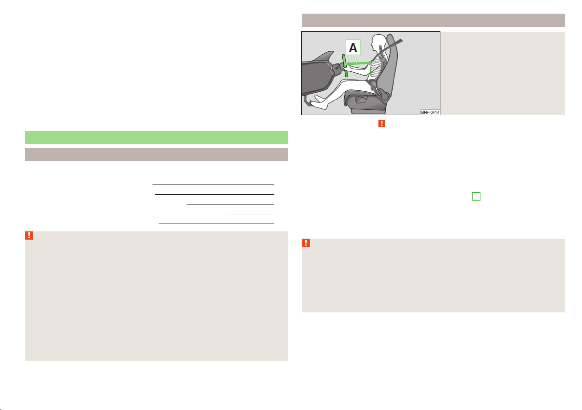
Fig. 1
Correct seated position for the
driver
Read and observe on page 7 first.
For your own safety and to reduce the risk of injury in the event of an accident,
the following instructions must be observed.
Adjust the driver’s seat in the forward/back direction so that the pedals
can be fully depressed with slightly bent legs.
Adjust the seat backrest so that the highest point of the steering wheel
7
can be reached with your arms at a slight angle.
Adjust the steering wheel so that the distance A between the steering
wheel and your chest is at least 25 cm » Fig. 1.
Correctly fasten the seat belt » page 11.
Driver seat adjustment » page 50, Adjusting the front seats.
WARNING
■
Always assume the correct seated position before setting off and do not
change this position while driving. Also advise your passengers to adopt
the correct seated position and not to change this position while the car is
moving.
■
Maintain a distance of at least 25 cm to the steering wheel. Not maintaining this minimum distance will mean that the airbag system will not be able
to properly protect you – hazard!
Passive Safety
7
Page 10
WARNING (Continued)
■
When driving, hold the steering wheel with both hands firmly on the outer edge in the “9 o'clock” and “3 o'clock” position. Never hold the steering
wheel in the “12 o'clock” position or in any other way (e.g. in the middle or
inner edge of the steering wheel). In such cases, you could severely injure
the arms, hands and head when the driver airbag is deployed.
■
Ensure that there are no objects in the driver's footwell as they may get
caught behind the pedals when driving or applying the braking. You would
then no longer be able to operate the clutch, brake or acceleration pedals.
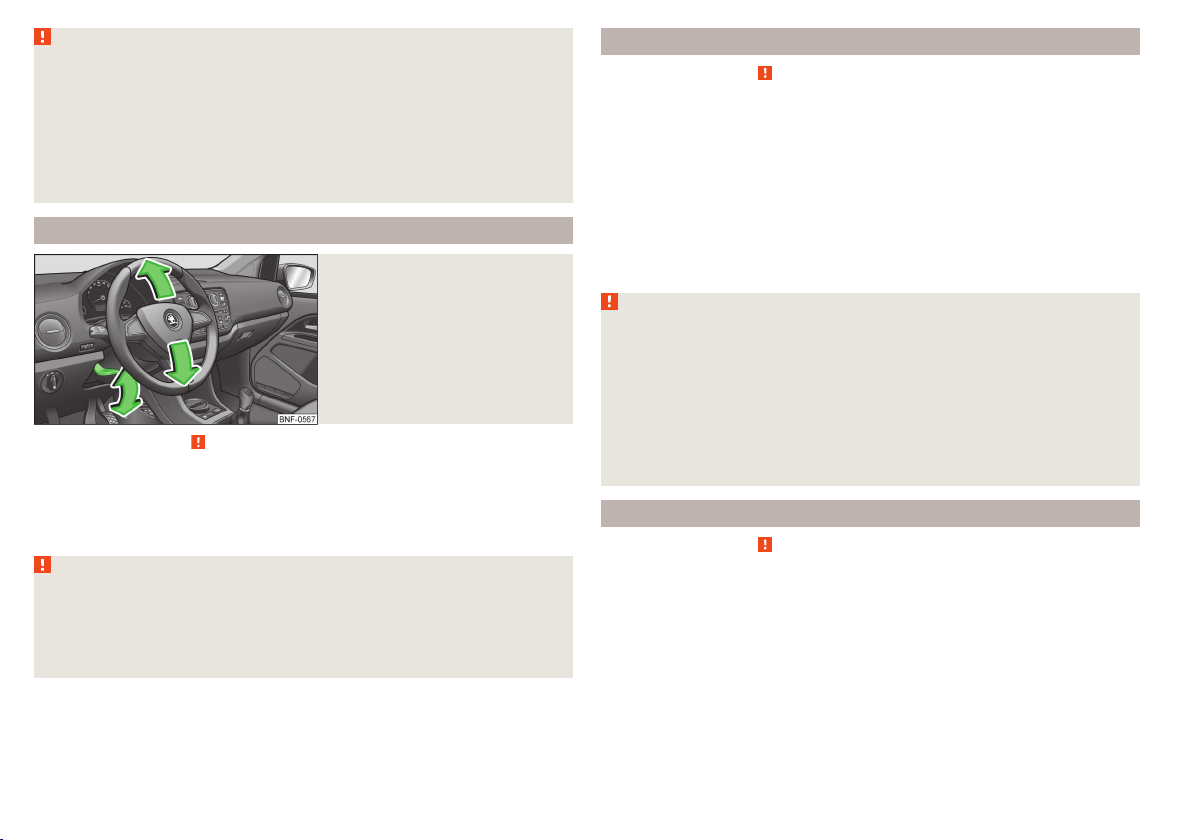
Adjusting the steering wheel position
Fig. 2
Adjusting the steering wheel position
Read and observe on page 7 first.
The height of the steering wheel can be adjusted.
Swivel the lever underneath the steering wheel downwards » Fig. 2.
›
Adjust the height of the steering wheel to the desired position.
›
Push the lever upwards to the stop.
›
WARNING
■
The lever for adjusting the steering wheel must be locked whilst driving
so that the position of the steering wheel cannot accidentally change during the journey – risk of accident!
■
Never adjust the steering wheel when the vehicle is moving only when
the vehicle is stationary!
Correct seated position for the front passenger
Read and observe on page 7 first.
For passenger safety and to reduce the risk of injury in an accident, the following instructions must be observed.
Position the front passenger seat back as far as possible. The front pas-
senger must maintain a distance of at least 25 cm to the dash panel so
that the airbag offers the greatest possible safety if it is deployed.
Correctly fasten the seat belt » page 11.
Front passenger adjustment » page 50, Adjusting the front seats.
In exceptional cases the front passenger airbag can be deactiva-
ted » page 16, Deactivating airbags.
WARNING
■
Maintain a distance of at least 25 cm to the dash panel. Not maintaining
this minimum distance will mean that the airbag system will not be able to
properly protect you – hazard!
■
Always keep your feet in the footwell when the car is being driven – never place your feet on the instrument panel, out of the window or on the
surfaces of the seats. You will be exposed to increased risk of injury if it becomes necessary to apply the brake or in the event of an accident. If an airbag is deployed, you could suffer fatal injuries by adopting an incorrect
seated position!
Correct seated position for the passengers in the rear seats
Read and observe on page 7 first.
To reduce the risk of injury in the event of a sudden braking manoeuvre or an
accident, the occupants on the rear seats must observe the following.
Adjust the head restraint so that the top edge of the head restraint is at
the same level as the upper part of your head.
Correctly fasten the seat belt » page 11.
Use a suitable child restraint system if transporting children in the vehi-
cle » page 18, Transporting children safely.
Adjust head restraints » page 51.
8
Safety
Page 11

Examples of incorrect seated positions
Read and observe on page 7 first.
Maximum seat belt protection is only achieved if seat belts are fastened correctly.
Incorrect seated positions considerably reduce the protective functions of the
seat belts and therefore increase the risk of injury due to an incorrect routing
of the seat belt.
The driver is fully responsible for himself and passengers, especially children.
Never allow a passenger to adopt an incorrect seated position when the car is
moving.
The following list contains instructions which, if not observed, may cause serious injuries or death. This list is not complete, however we would like you to
familiarise yourself with this subject.
Observe the following instructions while driving.
Do not stand up.
Do not stand on the seats.
Do not kneel on the seats.
Do not tilt the seat backrest too far back.
Do not lean against the dash panel.
Do not lie on the rear seats.
Do not sit only on the front part of the seat.
Do not sit facing to the side.
Do not lean out of the window.
Do not put your feet out of the window.
Do not put your feet on the dash panel.
Do not put your feet on the seat cushion.
Do not allow anybody to travel in the footwell.
Do not drive without fastening your seat belt.
Do not delay in the luggage compartment.
Seat belts
Using seat belts
Introduction
Fig. 3
Driver wearing seat belt
This chapter contains information on the following subjects:
The physical principle of a frontal collision 11
Fastening and unfastening seat belts 11
Seat belts that are fastened correctly offer good protection in the event of an
accident. They reduce the risk of an injury and increase the chance of survival
in the event of a major accident.
Correctly fastened seat belts hold occupants of the car in the correct seated
position » Fig. 3.
The seat belts reduce the kinetic energy (energy of motion) to a considerable
extent. They also prevent uncontrolled movements which, in turn, may well result in severe injuries.
Occupants of a vehicle who have correctly fastened their seat belts have the
major benefit of the fact that the kinetic energy is absorbed as effectively as
possible by the belts.
The structure of the front end of the vehicle and other passive safety measures, such as the airbag system, also contribute to the kinetic energy being reduced as effectively as possible. The energy produced is thus absorbed and
there is less risk of injury.
Particular safety aspects must be observed when transporting children in the
vehicle » page 18, Transporting children safely.
Seat belts
9
Page 12

WARNING
■
Fasten your seat belt before each journey – even when driving in town!
This also applies to the passengers seated at the rear – risk of injury!
■
Expectant women must also always wear a seat belt. This is the only way
of ensuring optimal protection for the unborn child » page 11.
■
Maximum seat belt protection is only achieved if you are correctly seat-
ed » page 7, Correct and safe seated position.
■
The seat backrests of the front seats must not be tilted too far to the rear
otherwise the seatbelts can lose their effectiveness.
WARNING (Continued)
■
Many layers of clothing and loose clothing (e. g. a winter coat over a jacket) do not allow you to be correctly seated and impairs proper operation of
the seat belts.
■
It is prohibited to use clamps or other objects to adjust seat belts (e. g. for
shortening the belts for smaller persons).
■
The seat belts for the rear seats can only fulfil their function reliably
when the seat backrests are correctly locked into position » page 53, Seat
backrests.
WARNING
Information on the correct routing of the belt
■
Always ensure that the webbing of the seat belts is properly routed. Seat
belts which are not correctly adjusted can themselves cause injuries even
in minor accidents.
■
A seat belt which is hanging too loose can result in injuries as your body is
moved forward by the kinetic energy produced in an accident and is then
suddenly held firm by the belt.
■
The belt webbing must not run across solid or fragile objects (e.g. spectacles, ball-point pens, bunches of keys etc.). Such objects can cause injury.
WARNING
Information on dealing with the safety belts
■
The belt webbing must not be jammed in-between at any point or twisted, or chafe against any sharp edges.
■
Make sure you do not catch the seat belt when closing the door.
WARNING
Information on the proper use of the safety belts
■
Never use one seat belt to secure two persons (including children). The
seatbelt must not be placed over a child who is sitting on the lap of another
passenger.
■
The lock tongue should only be inserted into the lock which is the correct
one for your seat. Wrong use of the safety belt will reduce its capacity to
protect and the risk of injury increases.
■
The slot of the belt tongue must not be blocked, otherwise the belt
tongue will not lock in place properly.
WARNING
Information on the care and maintenance of the safety belts
■
The belt webbing must always be kept clean. Soiled belt webbing may im-
pair proper operation of the inertia reel » page 96, Safety belts.
■
The seat belts must not be removed or changed in any way. Do not at-
tempt to repair the seat belts yourself.
■
Check the condition of all the seat belts on a regular basis. If any damage
to the seat belts, seat belt connections, inertia reel or the lock is detected,
the relevant seat belt must be replaced by a specialist garage.
■
Damaged seat belts which have been subjected to stress in an accident
and were therefore stretched, must be replaced – this is best done by a
specialist garage. The anchorage points of the belts must also be inspected. The anchorage points for the belts should also be checked.
Note
The national legal requirements must be observed when using seat belts.
10
Safety
Page 13

The physical principle of a frontal collision
Fig. 4 Driver without a fastened seat belt/rear seat passenger without a
fastened seat belt
Read and observe on page 10 first.
As soon as the vehicle is moving, so-called kinetic energy (the energy of motion) is produced both in terms of the car as well as in terms of the occupants.
The magnitude of this kinetic energy depends essentially on the speed at
which the vehicle is travelling and on the weight of the vehicle including the
occupants. The greater the speed and weight increase, the greater the
amount of energy which has to be absorbed in the event of an accident.
The speed of the vehicle is the most important factor. Doubling the speed of
the vehicle from 25 km/h up to 50 km/hour increases the kinetic energy four
times.
The idea that it is possible to support your body with your hands in a minor accident is incorrect. Even in a collision at only a low speed, the forces acting on
the body are such that it is no longer possible to support your body.
Even if you only drive at a speed of 30-50 km/h, the forces that your body is
exposed to in the event of an accident can exceed a metric ton (1000 kg).
For example, a person's weight of 80 kg “increases” to 4.8 tons (4800 kg) at
50 km/h.
In the event of a frontal collision, occupants of the car not wearing a seat belt
are thrown forward and strike parts of the interior of the car, such as the
steering wheel, dash panel, windscreen in ways which cannot be controlled » Fig. 4 - . In certain circumstances you could even be thrown out of the
vehicle, which could cause life threatening or even fatal injuries.
It is also important that rear passengers fasten their seat belts, as they could
otherwise be thrown through the vehicle in an uncontrolled manner in the
event of an accident.
A rear seat passenger who has not fastened their seat belt is a danger not only to himself but also for those seated at the front » Fig. 4 – .
Fastening and unfastening seat belts
Fig. 5 Fastening/unfastening the seat belt
Fig. 6 Routing of belt webbing over the shoulders and the lap belt/Rout-
ing of belt webbing for an expectant mother
Read and observe on page 10 first.
Fastening
Correctly adjust the front seat before fastening the seat belt » page 7, Cor-
›
rect and safe seated position.
Use the lock tongue to slowly pull the webbing over your chest and pelvis.
›
Seat belts
11
Page 14

Insert the lock tongue into the belt buckle » Fig. 5 – that is part of the seat
›
until it clicks into place.
Pull on the belt to check that it has engaged correctly in the lock.
›
A plastic knob in the belt webbing holds the belt tongue in a position which is
easy to get hold of.
It is important that the belt is properly routed to ensure seat belts offer the
maximum protection.
The shoulder part of the seat belt must never run across the neck but must
roughly run over the middle of the shoulder and fit snugly against the chest.
The lap part of the belt must run across the pelvis, must not be positioned
across the stomach and must always fit snugly » Fig. 6 – .
Expectant women must also always wear a seat belt. This is the only way of
ensuring optimal protection for the unborn child.
On expectant mothers, the lap part of the belt must be positioned as low as
possible on the pelvis to avoid exerting any pressure on the lower abdomen » Fig. 6 – .
Releasing
Release the seat belt only when the vehicle is stationary.
Press the red button in the belt buckle » Fig. 5 – , the lock tongue pops
›
out.
Manually guide the belt back so that it is easier to fully roll up the webbing,
›
the seat belt does not twist.
CAUTION
When releasing the seatbelt ensure that the tongue of the lock does not damage the door trim or other parts of the interior.
Inertia reels and belt tensioners
Introduction
This chapter contains information on the following subjects:
Inertia reels 12
Belt tensioners
Inertia reels
Each seat belt is equipped with an inertia reel.
When pulling slowly on the seat belt, the belt can move freely. When pulling
sharply on the seat belt, the movement is locked by the inertia reel.
The belts also lock when full braking, when the car accelerates, when driving
downhill and when cornering.
WARNING
If the seat belt does not lock when pulling sharply on it, have it inspected
immediately by a specialist garage.
Belt tensioners
Safety for the driver and front passenger wearing their seat belts is enhanced
by the belt tensioners fitted to the inertia reels of the front three-point seat
belts.
The three-point seat belts are automatically tensioned in the event of a frontal
collision of a certain severity. The belt tensioners can also be deployed if the
seat belts are not fastened.
The seat belts are automatically tensioned in the event of a collision of a certain severity.
Belt tensioners are not activated in the event of minor frontal collisions, side
and rear-end collisions, in the case of a rollover and also not in accidents in
which no major forces are produced from the front.
WARNING
■
Any work on the belt tensioner system including removal and installation
of system components because of other repair work, must only be carried
out by a specialist garage.
■
The protective function of the system is only adequate for a single accident. If the belt tensioners have been deployed, it is then necessary to replace the entire system.
Note
■
Smoke is generated when the belt tensioners are deployed. This is not an in-
dication of a fire in the vehicle.
■
When disposing of the vehicle or parts of the belt tensioner system, it is im-
12
portant to comply with national legal requirements. ŠKODA service partners
are familiar with these regulations and will be able to provide you with detailed information.
12
Safety
Page 15

Airbag system
Description of the airbag system
Introduction
This chapter contains information on the following subjects:
System description 13
Airbag deployment 13
WARNING
■
An airbag can only offer you optimal protection in combination with a
fastened seat belt.
■
The airbag is not a substitute for the seat belt, but instead forms part of
the complete passive vehicle safety concept.
■
To ensure passengers are protected with the greatest possible effect
when the airbag is deployed, the front seats must be correctly adjusted to
match the body size » page 7, Correct and safe seated position.
■
If you do not fasten the seat belts when driving, lean too far forward or
adopt an incorrect seated position, you are exposing yourself to increased
risk of injury in the event of an accident.
WARNING
Information on the use of the airbag system
■
If there is a fault, the airbag system must be checked by a specialist garage immediately. Otherwise, there is a risk that the airbag will not be deployed in the event of an accident.
■
No modifications of any kind must be made to parts of the airbag system.
■
Any work on the airbag system including the installation and removal of
system components due to other repair work (e.g. removal of the steering
wheel) must only be carried out by a specialist garage.
■
Never make any changes to the front bumper or bodywork.
■
It is prohibited to manipulate individual parts of the airbag system as this
might result in the airbag being deployed.
■
The protective function of the airbag system is sufficient for only one accident. The airbag system must then be replaced if the airbag has been deployed.
System description
Read and observe on page 13 first.
The functional status of the airbag system is indicated by the indicator light
in the instrument cluster » page 33.
When the airbags are deployed, they fill with gas and inflate.
A grey white or red, non-harmful gas is released when the airbag is inflated.
This is perfectly normal and is not an indication of a fire in the vehicle.
Depending on the vehicle equipment, the airbag system consists of the
following modules.
Electronic control unit.
›
Front airbag for the driver and the front passenger » page 14.
›
Side airbags Head-thorax » page 15;
›
Airbag warning light in the instrument cluster » page 33, Airbag system.
›
Key switch for the front passenger airbag » page 17.
›
Warning light for the front passenger airbag deactivation/activation in the
›
middle of the dash panel » page 17.
Note
■
The airbag system needs no maintenance during its working life.
■
If you sell your vehicle, provide the complete vehicle documentation to the
new owner. Please note that the information relating to the possibility of deactivating the front passenger airbag must be included!
■
When disposing of vehicle or parts of the airbag system, it is important to
comply with the national legal requirements.
Airbag deployment
Read and observe
The airbags inflate in fractions of a second and at a high speed in order to be
able to offer additional protection in the event of an accident.
The airbag system is only functional when the ignition is switched on.
In certain accident situations, several airbags may be deployed simultaneously.
The airbags are not deployed in the case of minor frontal and side collisions,
rear-end collisions, tilting of the vehicle and vehicle rollover.
on page 13 first.
Airbag system
13
Page 16

Deployment factors
It is not possible to generally determine which deployment conditions apply to
the airbag system in every situation. An important role is played by factors
such as the type of object that the vehicle hits (hard/soft), the impact angle,
vehicle speed etc.
A decisive factor for the deployment of the airbags is the deceleration which
occurs. The control unit analyses the nature of the collision and activates the
relevant restraint system.
If the vehicle deceleration which occurs and is measured during the collision
remains below the prescribed reference values specified in the control unit,
the airbags are not deployed although the vehicle may well suffer severe damage to the bodywork as a consequence of the accident.
The following airbags will be deployed in the event of a severe frontal
collision.
Driver’s front airbag.
›
Front passenger airbag.
›
The following airbags will be deployed in the event of a severe side collision.
Head-Thorax side airbag on the crash side.
›
In the event of an accident in which the airbags are deployed:
the interior lighting comes on (if the switch for the interior light is in the door
›
contact position),
the hazard warning light is switched on;
›
all the doors are unlocked;
›
the fuel supply to the engine is interrupted.
›
Front airbags
Fig. 7 Driver airbag in the steering wheel/front passenger airbag in the
dashboard
Fig. 8 Safe distance to steering wheel/gas-filled airbags
Airbag overview
Introduction
This chapter contains information on the following subjects:
Front airbags
Side airbags Head-Thorax 15
14
Safety
In the event of a severe frontal collision, the front airbag system offers additional protection for the head and chest area of the driver and front passenger.
The front airbag for the driver is housed in the steering wheel » Fig. 7 – .
The front airbag for the front seat passenger is located in the dash panel
14
above the stowage compartment » Fig. 7 – .
When the airbags are deployed, they inflate in front of the driver and front
passenger » Fig. 8 - . The forward movement of the driver and of the front
passenger is cushioned when they make contact with the fully inflated airbag
and the risk of injury to head and chest is thus reduced.
Page 17

WARNING
Information on correct seated position
■
For the driver and front passenger, it is important to maintain a distance
of at least 25 cm to the steering wheel or dashboard A » Fig. 8. Not maintaining this minimum distance will mean that the airbag system will not be
able to properly protect you – hazard! The front seats must always also be
correctly adjusted to match the body size of the occupant.
■
The airbag develops enormous forces when triggered, which can lead to
injuries if the sitting position or seated position is not correct.
■
There must not by any further persons, animals or objects positioned between the front seated occupants and the deployment area of the airbag.
Side airbags Head-Thorax
WARNING
Front airbag and transporting children
■
Never transport children on the front seat of a vehicle without using a
proper restraint system. If airbags are deployed in the event of an accident,
the child might suffer severe or even fatal injuries!
■
The front passenger airbag must be deactivated if using a rear-facing
child seat on the front passenger seat » page 17, Deactivating the front
passenger airbag. If this is not done, there is a risk of the child suffering severe or even fatal injuries if the front passenger airbag is deployed. When
transporting a child on the front passenger seat, pay attention to any relevant national regulations regarding the use of child safety seats.
WARNING
General information
■
The steering wheel and the surface of the airbag module in the dash panel on the passenger side must not have stickers attached, be covered or
modified in any other way. These parts should only be cleaned with a cloth
that is dry or has been moistened with water. No objects such as cup holders, mobile phone mounts, etc. must be attached to the covers of the airbag modules or be located within their immediate vicinity.
■
Never place objects on the surface of the front passenger airbag module
in the dash panel.
Fig. 9 Place of installation of the side airbag/deployment area of the side
airbag
In the event of severe side collisions, the side airbag system Head-Thorax provides additional protection for the upper body (chest, stomach and pelvis) of
passengers in the vehicle.
The side airbags are housed in the upholstery of the seat backrests of the
front seats » Fig. 9 – .
When the side airbags » Fig. 9 - are triggered, the belt tensioner is also deployed automatically on the relevant side.
The load of the occupants is cushioned when plunging into the fully inflated
airbag and the risk of injury to the head and upper body (chest, stomach and
pelvis) is reduced on the side facing the door.
WARNING
Information on correct seated position
■
Your head should never be positioned in the deployment area of the side
airbag. You might suffer severe injuries in the event of an accident. This applies in particular to children who are transported without using a suitable
child safety seat » page 19, Child safety and side airbag.
■
There must not be any further persons, animals or objects positioned between the occupants and the deployment area of the airbag. No accessories, such as cup holders, should be attached to the doors.
■
If children adopt an incorrect seated position when travelling, they may
be exposed to an increased risk of injury in the event of an accident. This
can result in serious injuries » page 18, Child seat.
Airbag system
15
Page 18

WARNING
The airbag control unit operates using pressure sensors located in the front
doors. For this reason, no adjustments may be carried out to the doors or
door panels (e.g. installation of additional loudspeakers). Resulting damage
can have a negative impact on the function of the airbag system. Any work
on the front doors and door panels must be carried out by a specialist garage. The following instructions must be observed.
■
Never drive with inner door panels removed.
■
Never drive if parts of the inner door panel have been removed and the
resulting openings have not been properly sealed.
■
Never drive if the loudspeakers in the doors have been removed, unless
the loudspeaker openings have been properly sealed.
■
Always make sure that the openings are covered or filled if additional
loudspeakers or other equipment parts have been installed in the inner
door panels.
■
Always have work carried out by a ŠKODA service partner or a professional specialist garage.
WARNING
■
Only hang light items of clothing on the hooks fitted in the vehicle. Never
leave any heavy or sharp-edged objects in the pockets of the items of
clothing.
■
Ensure that there are no excessive forces, such as violent knocks, kicks
etc., impact on the backrests of the seats otherwise the system may be
damaged. The side airbags would not be deployed in such a case!
■
Any seat or protective covers which you fit to the driver or front passenger seats must only be of the type expressly authorized by ŠKODA. In view
of the fact that the airbag inflates out of the backrest of the seat, use of
non-approved seat or protective covers would considerably impair the protective function of the side airbag.
■
Any damage to the original seat covers in the area of the side airbag module must be repaired immediately by a specialist garage.
■
The airbag modules in the front seats must not display any damage,
cracks or deep scratches. It is not permissible to use force in order to open
the modules.
Deactivating airbags
Introduction
This chapter contains information on the following subjects:
Deactivating airbags
Deactivating the front passenger airbag 17
Deactivating airbags
Deactivating an airbag should be considered in cases such as the ones below.
If using a rear-facing child seat on the front passenger seat (due to different
›
legal regulations, the airbag must be deactivated if using a forwards-facing
child seat in some countries) » page 18, Transporting children safely.
If it is not possible to maintain a distance of at least 25 cm between the mid-
›
dle of the steering wheel and chest, despite the driver's seat being correctly
adjusted.
If special attachments are required in the area of the steering wheel because
›
of a physical disability.
If different seats have been fitted (e.g. orthopaedic seats without side air-
›
bags).
The front passenger airbag can be switched off with the key-operated
switch » page 17.
We recommend that you ask a ŠKODA service partner to deactivate any other
airbags.
Monitoring the airbag system
The operational capability of the airbag system is monitored electronically, including when one of the airbags is switched off.
Airbag deactivated using diagnostic equipment
The warning light lights up for approx. 3 seconds after switching on the
›
ignition and then flashes again for approx. 12 seconds.
Front passenger airbag deactivated using the key switch in the storage compartment
The warning light lights up for approx. 3 seconds after switching on the
›
ignition.
The warning light
›
the ignition has been turned on.
3 » Fig. 10 on page 17 lights up after
16
16
Safety
Page 19
Note
■
The national regulations for switching off airbags must be observed.
■
A ŠKODA service partner will be able to inform you which, if any, of your vehi-
cle's airbags can or must be deactivated.
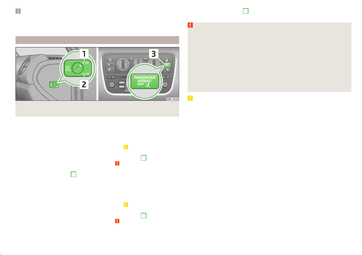
Deactivating the front passenger airbag
Fig. 10 Key switch for front passenger airbag/warning light for front passenger airbag activation/deactivation
Only the front passenger airbag is deactivated with the key switch.
Switching off
Switch off the ignition.
›
Open the passenger door.
›
Fold the key bit out completely for the radio key » .
›
Carefully insert the key into the key slot in the key switch as far as the stop.
›
Use the key to turn the slot of the key switch into position 2 » Fig. 10 OFF.
›
Pull the key out of the slot in the key switch » .
›
Close the passenger door.
›
Check that warning light 3
›
panel lights up after the ignition is switched on.
Switching on
Switch off the ignition.
›
Open the passenger door.
›
Fold the key bit out completely for the radio key » .
›
Carefully insert the key into the key slot in the key switch as far as the stop.
›
Use the key to turn the slot of the key switch into position 1 » Fig. 10 ON.
›
Pull the key out of the slot in the key switch » .
›
Close the passenger door.
›
in the middle of the dash
Check that warning light 3 in the middle of the dash
›
panel does not light up after the ignition is switched on.
WARNING
■
The driver is responsible for whether the airbag is switched on or switch-
ed off.
■
Only switch off the airbag when the ignition is switched off! Otherwise a
fault can occur in the system for deactivating the airbag.
■
If the warning light
bag will not be deployed in the event of an accident! Have the airbag system checked by a specialist garage immediately.
■
The key cannot be inserted in the key switch while driving.
■
Shocks can cause the key to turn in the slot and trigger the airbag!
■
The airbag could be triggered unexpectedly in an accident - it may result
in injury or death!
CAUTION
An insufficiently folded out key bit can damage the key switch!
flashes, the front passenger air-
Airbag system
17
Page 20

Transporting children safely
Child seat
Introduction
This chapter contains information on the following subjects:
Use of a child seat on the front passenger seat 18
Child safety and side airbag 19
Classification of child seats 20
Use of child seats fastened with a seat belt 20
Children are generally safer on the rear seats than on the front passenger
seat.
In contrast to adults, the muscles and bone structure of children are not yet
fully developed. Thus children are exposed to increased risk of injury.
Children should be transported in accordance with the relevant statutory provisions.
Child seats that comply with the ECE-R 44 standard must be used. The ECE-R
standard stands for: Economic Commission for Europe – Regulation.
Child seats that comply with the ECE-R 44 standard are identified with a test
mark that cannot be removed: a large E within a circle with the test number
below.
WARNING
■
The national legal requirements must be observed when using child
seats.
■
One should never carry children, and also not babies! - on one's lap.
■
Never leave children unattended in the vehicle. Certain outside climatic
conditions can cause life-threatening temperatures in the vehicle.
■
The child must be secured in the vehicle during the entire journey! Otherwise, the child would be thrown through the vehicle in the event of an accident, causing fatal injuries to both the child and other occupants.
■
Children are exposed to an increased risk of injury in the event of an accident if they lean forward or adopt an incorrect seated position when the
vehicle is moving. This particularly applies to children who are transported
on the front passenger seat as they can suffer severe, or even fatal injuries
if the airbag system is deployed!
WARNING (Continued)
■
Pay particular attention to the information provided by the manufacturer
of the child safety seat regarding the correct routing of the belt. Seat belts
which are not correctly adjusted can themselves cause injuries even in minor accidents.
■
Safety belts must be checked to ensure that they are running properly.
One should also ensure that the belt is not damaged by sharp-edged fittings.
■
The front passenger airbag must be deactivated if using a rear-facing
child seat on the front passenger seat. Further information » page 18, Use
of a child seat on the front passenger seat.
Note
We recommend that you use child seats from ŠKODA Original Accessories.
These child seats were developed and also tested for use in ŠKODA vehicles.
They meet the ECE-R 44 standard.
Use of a child seat on the front passenger seat
Never use a backwards-facing child restraint system on a seat that is protected by an active airbag installed in front of it. This could cause the child severe
injury or even death.
Fig. 11
Sticker on the B column on the
front passenger side.
18
Safety
Page 21
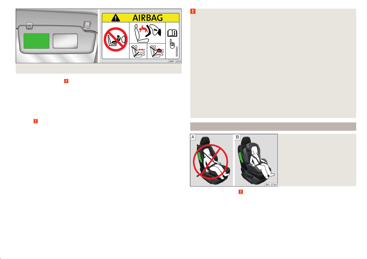
Fig. 12
Front passenger sun visor / label
Read and observe on page 18 first.
For safety reasons, we recommend that you install child seats on the rear
seats whenever possible.
The following instructions must be followed when using a child seat on the
front passenger seat.
The front passenger airbag must be deactivated if using a rear-facing child
›
seat » .
If possible, adjust the front passenger seat backrest so that it is as vertical,
›
so as to ensure secure contact between the passenger seat backrest and the
back of the child seat.
If possible, move the front passenger seat backwards so that there is no con-
›
tact between the front passenger seat and the child seat behind it.
With child safety seats in groups 2 or 3, make sure that the loop-around fit-
›
tings attached to the child seat headrest is positioned in front of or at the
same height as the loop-around fittings on the B pillar on the passenger side.
Set the height-adjustable front passenger seat as high up as possible.
›
Place and fasten the child seat on the seat and the child in the child seat ac-
›
cording to the specifications in the manufacturer's user manual of the child
seat .
WARNING
■
The front passenger airbag must be deactivated if using a rear-facing
child seat on the front passenger seat » page 16, Deactivating airbags.
■
Never use a rear-facing child seat on the front passenger seat if the pas-
senger airbag is activated. This child safety seat is positioned in the deployment area of the front passenger airbag. The airbag may cause the child severe, or even fatal injuries, in the event of it being deployed.
■
This fact is also indicated by the label that can be found in one of the fol-
lowing locations.
■
On the B-column on the front passenger side » Fig. 11. The sticker is visi-
ble upon opening the front passenger door.
■
On the front passenger's sun visor. In some countries, the sticker is lo-
cated on the front seat passenger's sun visor » Fig. 12.
■
With child safety seats in groups 2 or 3, make sure that the loop-around
fittings attached to the child seat headrest is positioned in front of or at
the same height as the loop-around fittings on the B pillar on the passenger side.
■
As soon as the rear-facing child seat is no longer being used on the passenger seat, the front passenger airbag should be re-activated again.
Child safety and side airbag
Fig. 13
Incorrect seated position of a
child who is not properly secured
– risk from the side airbag/Child
properly protected by safety seat
Read and observe on page 18 first.
The child must not be positioned in the deployment area of the side airbag » Fig. 13 – .
There must be sufficient room between the child and the deployment area of
the side airbag that the airbag can provide as much protection as possible » Fig. 13 – .
Transporting children safely
19
Page 22
WARNING
■
Children must never be seated with their head in the deployment area of
the side airbag – risk of injury!
■
Do not place any objects within the deployment area of the side airbags –
risk of injury!
Classification of child seats
Read and observe on page 18 first.
Classification of child seats according to the ECE-R 44 standard.
Group Weight of the child Approximate age
0 up to 10 kg up to 9 months
0+ up to 13 kg up to 18 months
1 9-18 kg up to 4 years
2 15-25 kg up to 7 years
3 22-36 kg over 7 years
Use of child seats fastened with a seat belt
Read and observe
Overview of the usability of child seats fastened with a seat belt on each of
the seats in accordance with the ECE-R 16 standard.
Group Front passenger seat Rear seats
0
up to 10 kg
0+
up to 13 kg
1
9-18 kg
2
15-25 kg
3
22-36 kg
Child seat category “Universal” - a child seat designed to be attached to
U
the seat using the seat belt.
on page 18 first.
U U
U U
U U
U U
U U
Fastening systems
Introduction
This chapter contains information on the following subjects:
Anchor eyelets for the ISOFIX system
Use of child seats with the ISOFIX system 21
Anchor eyelets for the TOP TETHER system 21
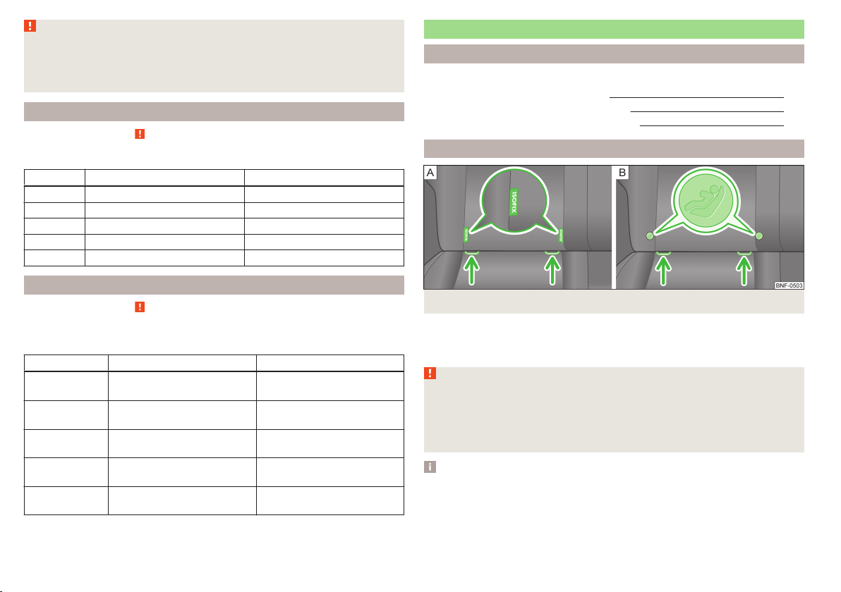
Anchor eyelets for the ISOFIX system
Fig. 14 Identification versions of anchor eyelets for child safety seats
There are two lashing eyes between the rear exterior seat backrest and the
surface of the seat itself on both sides for fixing the ISOFIXsystem » Fig. 14child seat in place.
WARNING
■
Always refer to the instructions from the manufacturer of the child seat
when installing and removing a child seat with the ISOFIX system.
■
Never attach other child seats, belts or objects to the anchor eyelets intended for the installation of a child seat with the ISOFIX system – risk to
life!
Note
■
A child seat fitted with the ISOFIX system can only be mounted in a vehicle
fitted with an ISOFIX system if the child seat has been approved for this type
of vehicle. Further information is available from a ŠKODA Partner.
■
Child seats with the ISOFIX system can be purchased from ŠKODA Original
Accessories.
20
20
Safety
Page 23

Use of child seats with the ISOFIX system
Overview of the usability of child seats with the ISOFIX system on each of the
seats in accordance with the ECE-R 16 standard.
Group
0
up to 10 kg
0+
up to 13 kg
Size class of
the child seat
a)
E X IL-SU
E
C
D
1
9-18 kg
C
B
B1
A
a)
The size category is shown on the label attached to the child seat.
The seat is suited for installation of an ISOFIX child seat with “Semi-
IL-SU
Universal” approval. The category “Semi-Universal” means that the child
seat with the ISOFIX system is approved for your vehicle. Observe the
list of vehicles that comes with the child seat.
The seat is suitable for the installation of an ISOFIX child seat with
IUF
“Universal” approval and attachment with the TOP TETHER belt.
The seat is not fitted with fixing eyes for the ISOFIX system.
X
Anchor eyelets for the TOP TETHER system
Fig. 15
Rear seat: TOP TETHER
Front passenger seat Rear seats
X IL-SUD
X
IL-SU
IUF
The anchor eyelets for attaching the belt of a child seat with the TOP TETHER
system are located on the back of the rear seat backrests » Fig. 15.
WARNING
■
Always refer to the instructions from the manufacturer of the child seat
when installing and removing a child seat with the TOP TETHER system.
■
Only use child seats with the TOP TETHER system on the seats with the
locking eyes.
■
Only ever attach one belt from the child seat to a locking eye.
■
On no account should you equip your vehicle, e.g. mount screws or other
anchorage points.
Transporting children safely
21
Page 24

Fig. 16 Cockpit
22
Using the system
Page 25

Using the system
Cockpit
Overview
1
Door opening lever 39
2
Electrical power window in the driver's door 40
3
Central locking system 38
4
Electric exterior mirror adjustment 49
5
Air outlet jet 65
6
Operating lever:
Turn signal lights and main beam, headlight flasher 44
›
Speed regulating system 80
›
7
Parking ticket holder 54
8
Steering wheel:
With horn
›
With driver’s front airbag 14
›
9
Instrument cluster: Instruments and warning lights 24
10
Operating lever:
Multifunction display 26
›
Windscreen wiper and wash system 47
›
11
Button for rear window heater 47
12
START-STOP button 81
13
Depending on equipment fitted:
Operating controls for the heating 65
›
Operating controls for the air conditioning system
›
14
Socket for the cradle for the Move & Funmultifunction device. 67
15
Warning light for the deactivated front seat passenger airbag 17
16
Interior rear-view mirror 49
17
Button for hazard warning light system 45
18
Front passenger airbag 14
19
Bag holder 58
20
Storage compartment on the front passenger side 58
21
Air outlet jet 65
22
Electric window raiser in the passenger door 40
23
Door opening lever 39
24
Light switch 43
25
Bonnet release lever 101
26
Regulator for headlamp beam adjustment for the headlights 43
27
Lever for adjusting the steering wheel 8
28
Ignition lock 71
29
Pedals 74
30
Regulator for left seat heating 52
31
Radio
32
Button for City Safe Drive system 83
33
Handbrake lever 72
34
Depending on equipment fitted:
Gearshift lever (manual gearbox) 73
›
Selector lever (automated gearbox) 74
›
35
Storage compartment 55
36
Regulator for right seat heating 52
Note
■
Cars with factory-fitted radio are supplied with separate instructions for op-
erating such equipment.
■
The arrangement of the controls and switches and the location of some
items on right-hand drive models may differ from that shown in » Fig. 16 . The
symbols on the controls and switches are the same as for left-hand drive models.
65
Cockpit
23
Page 26

Instruments and control lights
Instrument cluster
Introduction
This chapter contains information on the following subjects:
Overview 24
Speedometer 24
Fuel reserve display 25
Tachometer 25
Counter for distance driven 26
Service interval display 26
Gear recommendation 26
The instrument cluster gives the driver basic information such as the current
speed, engine speed, the state of some vehicle systems and the like.
WARNING
Concentrate fully at all times on your driving! As the driver you are fully responsible for road safety.
Overview
Fig. 18 Instrument cluster - Version 2
Read and observe
1
Speedometer » page 24
2
Display:
with fuel reserve gauge (option 1 only) » page 25
›
With counter for distance driven » page 26
›
With service interval display » page 26
›
With multifunction display » page 26
›
with outside temperature display » page 28
›
3
The counter for the distance travelled button (trip) » page 26
4
Fuel gauge » page 25
5
Engine revolutions counter » page 25
6
Adjust button for the time » page 29
on page 24 first.
Speedometer
Read and observe
The speedometer displays the current speed in km/h or mph and km/h.
on page 24 first.
Fig. 17 Instrument cluster - Version 1
24
Using the system
Page 27

Fuel reserve display
Fig. 19 Fuel gauge
Fig. 20
Fuel gauge - CNG
Read and observe on page 24 first.
Vehicles running on petrol
The fuel gauge » Fig. 19 only operates if the ignition is switched on.
The fuel tank has a capacity of about 35 litres.
If the fuel gauge in the fuel tank reaches the reserve capacity level, the warn-
ing symbol of on » Fig. 19 - will appear in the instrument cluster or the
symbol will flash for 10 seconds together with the remaining segments in
the instrument cluster display » Fig. 19 - . There are now about 4 litres of fuel
remaining in the tank.
An audible signal sounds as a warning signal.
Natural gas vehicles (CNG)
The fuel gauge » Fig. 20 only operates if the ignition is switched on.
1
Gasoline reserve
2
Natural gas reserve
When the vehicle runs on petrol, the pointer of the fuel gauge is in the range
1
» Fig. 20. When the vehicle runs on petrol, the pointer of the fuel gauge is
in the range 2.
If the fuel level in the fuel tank reaches the reserve area for petrol, the warn-
ing light goes on. The pointer is in the red range of the gauge 1 » Fig. 20.
There are now about 5 l of fuel remaining in the tank.
If the fuel level in the fuel tank reaches the reserve area for natural gas the
warning light goes on. The pointer is in the red range of the gauge
2
» Fig. 20. There are now about 1.5 kg of fuel remaining in the tank.
CAUTION
Never drive until the fuel tank is completely empty! The irregular supply of fuel
can cause misfiring. This can result in considerable damage to parts of the engine and the exhaust system.
Tachometer
Read and observe on page 24 first.
The tachometer 5 » Fig. 18 on page 24 shows the actual engine speed per minute.
The beginning of the red scale range of the tachometer indicates the maximum permitted engine speed of a driven-in and operating warm engine.
You should shift into the next highest gear before the red scale of the revolution counter is reached, or select mode D on the automatic gearbox.
The gear recommendation is important to note in order to maintain the optimum engine speed » page 26.
Avoid high engine speeds during the running-in period and before the engine
has warmed up to the operating temperature.
CAUTION
The pointer of the tachometer must reach the red area for only a short time there is a risk of engine damage!
Instruments and control lights
25
Page 28

Counter for distance driven
Read and observe on page 24 first.
To toggle between the odometer and the counter for the distance travelled
(trip), briefly press the button 3 » Fig. 17 on page 24 or » Fig. 18 on page 24.
Counter for distance travelled (trip)
The counter indicates the distance you have driven since it was last reset - in
steps of 100 metres or 1/10 of a mile.
Reset counter for distance travelled (trip)
Press and hold the 3 » Fig. 17 on page 24 or » Fig. 18 on page 24 button.
›
Odometer
The odometer indicates the total distance which the vehicle has been driven.
Service interval display
Read and observe
The service interval display shows the mileage to the next service event.
Before the next service interval has been reached, the message
the instrument cluster display for some seconds and the remaining kilometres
are shown after switching on the ignition.
If the time of the service has been reached, an acoustic signal will sound and
the message
The information regarding the service intervals can be found in the service
schedule.
Note
Information is retained in the Service Interval Display even after the vehicle
battery is disconnected.
appears for a few seconds after switching on the ignition.
on page 24 first.
appears in
Gear recommendation
Read and observe on page 24 first.
An information for the engaged gear is shown in the display of the instrument
cluster.
The function of the gear recommendation is to help reduce fuel consumption.
Show Importance
Recommended gear
The gear recommendation is intended only for vehicles with a manual transmission or for vehicles with an automatic transmission in manual shift mode
(Tiptronic).
On vehicles with a manual transmission in the display, the recommended gear
and the respective arrow symbol is displayed.
For vehicles with automated manual transmission mode for manual shifting
(Tiptronic), the currently engaged gear and the respective arrow symbol is
shown in the display.
WARNING
The driver is always responsible for selecting the correct gear in different
driving situations, such as overtaking.
For the sake of the environment
A suitably selected gear has the following advantages.
■
It helps to reduce fuel consumption.
■
It reduces the operating noise.
■
It protects the environment.
■
It benefits the durability and reliability of the engine.
Optimal gear engaged.
Recommendation that you shift to a higher gear.
Recommendation that you shift to a lower gear.
Multi-function display (MFD)
Introduction
This chapter contains information on the following subjects:
Operation
Memory 27
Multifunction display details 28
Warning at excessive speeds 29
29
27
26
Using the system
Page 29

The driving data is displayed on the multifunction display.
The multifunction display only operates if the ignition is switched on. After the
ignition is switched on, the function that was last selected before switching
off the ignition is displayed.
WARNING
■
Concentrate fully at all times on your driving! As the driver you are fully
responsible for the operation of your vehicle.
■
Even at temperatures of around +4 °C, black ice may still be on the road
surface! You should therefore not only rely on the outside temperature display for accurate information as to whether there is ice on the road.
Note
In certain national versions the displays appear in the Imperial system of
measures.
Operation
Fig. 21
Buttons on the control lever
Read and observe on page 27 first.
Some features of the multi-function display can be operated with the buttons
on the control lever » Fig. 21.
Operation description
But-
ton
» Fig. 21
A
B
Action Operation
Briefly push up or down Select data / set data values
Press briefly View information / confirm specification
Memory
Fig. 22
Multi-function display - Display
example of the memory
Read and observe on page 27 first.
The multifunction display is equipped with two automatic memories, 1 and 2.
The display of the selected memory is displayed at the position indicated by
the arrow » Fig. 22.
Single-trip memory
Total trip memory
Select memory
Select the corresponding element of the multifunction display » page 28.
›
Confirm the element again to switch between the individual memories.
Reset memory
Select the corresponding element of the multifunction display » page 28.
›
Select the desired memory.
›
Press the button B » Fig. 21 on page 27 longer.
›
The following values of the selected memory are set to zero.
Average fuel consumption.
›
Distance driven.
›
Average speed.
›
Driving time
›
Single-trip memory (memory 1)
The single-trip memory collates the driving information from the moment the
ignition is switched on until it is switched off.
New data will also flow into the calculation of the current driving information if
the trip is continued within 2 hours after switching off the ignition.
Instruments and control lights
27
Page 30

If the trip is interrupted for more than 2 hours, the memory is automatically
erased.
Total-trip memory (memory 2)
The total distance driven memory gathers data from any number of individual
journeys up to a total of 19 hours and 59 minutes driving or 1,999 kilometres
driven.
The memory is deleted when either of these limits is reached and the calculation starts all over again.
Unlike the single-trip memory, the total-trip memory is not deleted after a period of interruption of driving of 2 hours.
Note
Disconnecting the vehicle battery will delete all memory data.
Multifunction display details
Read and observe on page 27 first.
Outside temperature
The current outside temperature is displayed.
If the outside temperature drops below +4 °C, the temperature indicator ap-
pears and a snow flake symbol (display for low temperature) flashes for a
few seconds, then remains displayed together with the outside temperature.
Driving time
The time travelled since the memory was last erased is displayed.
If you want to measure the time travelled from a particular moment in time on,
at this moment, reset the memory by setting the button to zero » page 27,
Memory.
The maximum distance indicated in both memories is 19 hours and 59 minutes.
The indicator is set back to zero if this period is exceeded.
Current fuel consumption
The current fuel consumption level is displayed in litres/100 km1). You can use
this information to adapt your driving style to the desired fuel consumption.
The display appears in litres/hour if the vehicle is stationary or driving at a low
speed2).
Average fuel consumption
The average fuel consumption since the memory was last erased is displayed
in litres/100 km1).
If you wish to determine the average fuel consumption over a certain period of
time, you must set the memory at the start of the new measurement to
zero » page 27. After erasing the memory, no value is displayed until you have
driven approx. 300 m.
The display is updated regularly while you are driving.
Range
The range indicates the distance you can still drive with your vehicle based on
the level of fuel in the tank and the same style of driving as before.
The display is shown in steps of 10 km. After the warning light for the fuel reserve » page 25, Fuel reserve displaylights up, the display is shown in steps of
5 km.
The fuel consumption over the last 50 km is used to calculate the information.
The range will increase if you drive in a more economical manner.
Distance travelled
The distance travelled since the memory was last erased is displayed.
If you want to measure the distance travelled from a particular moment in time
on, at this moment, reset the memory by setting the button to zero » page 27,
Memory.
The maximum distance indicated in both memories is 1 999 km. The indicator is
set back to zero if this period is exceeded.
Average speed
The average speed since the memory was last erased is displayed in km/hour .
To determine the average speed over a certain period of time, set the memory
to zero at the start of the measurement » page 27, Memory.
After erasing this data, no value appears in the display until you have driven
approx. 300 m.
1)
On some models in certain countries, the display appears in kilometres/litre.
2)
On some models in certain countries, the display appears in --,- kilometres/litres if the vehicle is stationary.
28
Using the system
Page 31

The display is updated regularly while you are driving.
Current driving speed
The current speed, which is identical to the display of the speedometer
1
» Fig. 18 on page 24 is displayed.
Coolant temperature
The current outside temperature is displayed.
Warning against excessive speeds
Set the speed limit, for example, for the maximum permissible speed in
town » page 29, Warning at excessive speeds.
Warning at excessive speeds
Read and observe on page 27 first.
Adjust the speed limit while the vehicle is stationary
Select the menu item (warning when limit is exceeded).
›
Activate the speed limit option by confirming this menu item (the value flash-
›
es).
Set the desired speed limit, e.g. 50 km/h.
›
Store the speed limit by confirming the set value, or wait several seconds;
›
your settings will be saved automatically.
This allows you to set the speed in 5 km/h intervals.
Adjusting the speed limit while the vehicle is moving
Select the menu item (warning when limit is exceeded).
›
Drive at the desired speed, e.g. 50 km/h.
›
Confirm the current speed as the speed limit.
›
If you wish to adjust the set speed limit, you can do so in 5 km/h intervals (e.g.
the accepted speed of 47 km/h increases to 50 km/h or decreases to 45 km/h).
Store the speed limit, or wait several seconds; your settings will be saved au-
›
tomatically.
Change or disable speed limit
Select the menu item (warning when limit is exceeded).
›
By confirming the stored value, the speed limit is disabled.
›
By reconfirming, the option to change the speed limit is activated.
›
If the set speed limit is exceeded, an audible signal will sound as a warning. At
the same time the message (warning against excessive speed) appears on
the display with the set limit value.
The set driving mode remains stored even after switching the ignition on and
off.
Read and observe on page 27 first.
The time is set as follows.
Select the time display on the instrument cluster » page 27, Operation.
›
Press the button
›
time display appears.
Press button 3 to change the value. For quick value change, hold down the
›
button.
Press button 6 to select the minutes display until it flashes.
›
Press button 3 to change the value. For quick value change, hold down the
›
button.
Confirm the set value by pressing the button6 again, or wait for around 5
›
seconds. The setting is saved automatically (the value stops flashing).
6
» Fig. 18 on page 24 and keep it pressed down until the
Warning lights
Introduction
This chapter contains information on the following subjects:
Handbrake 30
Braking system 30
Seat belt warning light 30
Generator 30
Engine oil
Coolant 31
Automated transmission 31
Power steering 32
Electronic Stability Control (ESC) 32
Traction Control System (TC)
Antilock brake system (ABS) 33
Tyre inflation pressure 33
Rear fog light 33
Exhaust inspection system 33
Engine electronics check 33
Airbag system 33
31
32
Instruments and control lights
29
Page 32

Handbrake - automatic transmission 34
Brake pedal (automatic transmission) 34
Turn signal system 34
Cruise control system 34
Main beam 34
/ Safety belt (belt status display) - rear seat 34
City Safe Drive
/ START-STOP 35
The warning lights indicate certain functions or faults.
The lighting up of some warning lights may be accompanied by acoustic sig-
nals.
After switching on the ignition, some warning lights light up briefly as a func-
tion test.
If the tested systems are OK, the corresponding warning lights go out a few
seconds after switching on the ignition or after starting the engine.
WARNING
■
Ignoring light-up indicator lamps in the instrument cluster and the control
symbols in the display may cause serious injury or damage to the vehicle.
■
If you have to stop for technical reasons, then park the vehicle at a safe
distance from the traffic, switch off the engine and activate the hazard
warning light system » page 45. The warning triangle must be set up at
the prescribed distance - observe the national legal provisions when doing
so.
■
The engine compartment of your car is a hazardous area. The following
warning instructions must be followed at all times when working in the engine compartment » page 101, Engine compartment.
34
Handbrake
Read and observe
The warning light illuminates if the handbrake is applied. An audible warning is also given if you drive the vehicle for at least 3 seconds at a speed of
more than 6 km/h.
on page 30 first.
Braking system
Read and observe on page 30 first.
The indicator light illuminates if the brake fluid level in the braking system
is too low or there is a fault in the ABS.
Stop the vehicle, switch off the engine, and check the level of the brake flu-
›
id » page 107 »
Further information » page 71, Brakes and parking.
WARNING
■
If the warning light is displayed simultaneously with warning light
» page 33, Antilock brake system (ABS), do not continue your
journey! Seek help from a specialist garage.
■
A fault to the ABS system or the braking system can increase the vehi-
cle's braking distance – risk of accident!
Seat belt warning light
Read and observe
The warning light illuminates as a reminder for the driver and front passenger to fasten seat belts.
The indicator light goes off after the respective seat belt has been fastened.
If the driver or front passenger has not fastened their seat belt and the vehicle
speed is more than 20 km/h, the warning light flashes and you will hear an
acoustic signal.
The warning signal is switched off and the indicator light is permanently lit
if the driver and front passenger have not fastened their seat belts within the
next 90 seconds.
Further information » page 9, Seat belts.
Generator
Read and observe on page 30 first.
If the warning light illuminates when the engine is running, the vehicle battery is not being charged.
.
on page 30 first.
30
Using the system
Page 33

Seek assistance from a specialist garage immediately. The electrical system requires checking.
If the warning light (cooling system fault) lights up in addition to the
warning light while driving, do not continue to drive!
Stop the engine - there is a risk of engine damage! Seek help from a specialist
garage.
Engine oil
Read and observe on page 30 first.
When the warning light is lit up or is flashing, the engine oil pressure is too
low.
Stop the vehicle and switch the engine off if the warning light does not go
›
off or if it begins to flash while you are driving.
An audible signal sounds as a warning signal.
Check the oil level and top up with engine oil if necessary » page 104, Check-
›
ing the oil level.
Do not continue your journey if for some reason it is not possible to top up the
engine oil under the prevailing conditions. This can cause serious engine damage. Therefore, switch the engine off and seek help from a specialist garage.
If the warning light flashes, do not drive any further, even if the oil level is
correct. Also do not leave the engine running at an idling speed.
Seek help from a specialist garage.
CAUTION
The red oil pressure light is not an oil level indicator! One should therefore
check the oil level at regular intervals, preferably after every refuelling stop.
Coolant
Read and observe
If the warning light lights up or flashes, either the coolant temperature is
too high or the coolant level is too low.
An audible signal sounds as a warning tone.
Stop the vehicle, switch off the engine, and check the coolant lev-
›
el » page 106, Checking the coolant level.
on page 30 first.
If the coolant level is too low, add coolant to the reservoir » page 106.
›
Do not continue your journey if for some reason it is not possible to top up the
coolant under the prevailing conditions. This can cause serious engine damage. Therefore, switch the engine off and seek help from a specialist garage.
If the coolant is within the specified range, the increased temperature may be
caused by an operating problem at the radiator fan.
Check the fuse for the radiator fan, replace if necessary » page 131, Fuses in
›
the engine compartment.
If the coolant level and fan fuse are both OK but the indicator light is nevertheless still illuminated, do not continue your journey!
Seek help from a specialist garage.
WARNING
■
Carefully open the coolant expansion bottle. If the engine is hot, the cooling system is pressurized – risk of scalding! It is therefore best to allow the
engine to cool down before removing the cap.
■
Do not touch the radiator fan. The radiator fan may switch itself on automatically even if the ignition is off - a danger of injury is present!
CAUTION
■
Additional headlights and other attached components in front of the air inlet
impair the cooling efficiency of the coolant.
■
Never cover the radiator - there is a risk of the engine overheating.
Automated transmission
Read and observe on page 30 first.
Warning light
If the warning light lights up and a beep sounds, then there is a fault to the
automated transmission. Do not continue to drive the vehicle! Switch off
the engine and seek assistance from a specialist garage.
Warning light
If the warning light lights up and no gear change is possible, there may be
technical reasons for why the functionality of the automatic transmission is
limited.
Stop the car, turn the ignition off and on again.
›
Instruments and control lights
31
Page 34

If the warning light lights up after you switch on the ignition, seek assistance from a specialist garage.
If the warning light or also the warning light lights up and an acoustic
signal sounds, this means that the automatic gearbox has overheated.
Stop and allow the transmission to cool down or drive more quickly than
›
20 km/h (12 mph).
If the warning light lights up repeatedly, park the vehicle, shut off the engine and allow the gearbox to cool down.
Further information » page 74, Automated transmission.
Power steering
Read and observe on page 30 first.
If the warning light
ignition does not go out, there is an error in the electromechanical power
steering.
If the indicator light
steering and the steering assist has failed (significantly higher steering forces).
If the indicator light
steering and the steering forces can be greater.
Stop the car, turn the ignition off and on again.
›
If the indicator light does not illuminate after the engine has been turned on
again, the power steering is fully operational again.
If the warning light lights up again, then immediately obtain assistance from
an authorised dealer.
Note
If the vehicle's battery has been disconnected and reconnected, the warning
light comes on after switching on the ignition. If the warning light does
not go out after moving a short distance, this means there is an error in the
system. Seek assistance from a specialist garage immediately.
or
comes on while driving or after switching on the
lights up, this indicates a complete failure of the power
lights up, this indicates a partial failure of the power
Electronic Stability Control (ESC)
Read and observe
The warning light flashes to show that the ESC is currently operating.
on page 30 first.
If the warning light illuminates, there is a fault in the ESC. Seek assistance
from a specialist garage immediately.
As the ESC operates in conjunction with the ABS, the ESP warning light will also come on if the ABS system fails.
If the warning light illuminates immediately after you start the engine, the
ESC might be switched off due to technical reasons.
Switch the ignition off and on again.
›
If the indicator light does not illuminate after you switch the engine back
on, the ESR is fully functional again.
Further information » page 78, Electronic Stability Control (ESC).
Note
If the vehicle's battery has been disconnected and reconnected, the warning
light comes on after switching on the ignition. If the warning light does
not go out after moving a short distance, this means there is an error in the
system. Seek assistance from a specialist garage immediately.
Traction Control System (TC)
Read and observe on page 30 first.
The warning light flashes to show that the ESC is currently operating.
If the warning light illuminates, there is a fault in the ESC. Seek assistance
from a specialist garage immediately.
The fact that the TCS operates together with the ABS means that the TCS
warning light will also come on if the ABS system is not operating properly.
If the warning light illuminates immediately after you start the engine, the
ESC might be switched off due to technical reasons.
Switch the ignition off and on again.
›
If the indicator light does not illuminate after you switch the engine back
on, the ESR is fully functional again.
Further information » page 78, Traction Control System (TC).
32
Using the system
Page 35

Note
If the vehicle's battery has been disconnected and reconnected, the warning
light comes on after switching on the ignition. If the warning light does
not go out after moving a short distance, this means there is an error in the
system. Seek assistance from a specialist garage immediately.
Note
If the vehicle's battery has been disconnected and reconnected, the warning
light comes on after switching on the ignition. If the warning light does
not go out after moving a short distance, this means there is an error in the
system. Seek assistance from a specialist garage immediately.
Antilock brake system (ABS)
Read and observe on page 30 first.
If the warning light illuminates, there is a fault in the ABS.
The vehicle will only be braked by the normal brake system without the ABS.
Seek assistance from a specialist garage immediately.
In the event of an ABS fault, the other braking and stabilization systems are
turned off » page 78, Braking and stabilisation systems .
WARNING
■
A fault to the ABS system or the braking system can increase the vehi-
cle's braking distance – risk of accident!
■
If the ABS warning light together with the indicator light » page 30
lights, do not continue to drive! Seek help from a specialist garage.
Tyre inflation pressure
Read and observe on page 30 first.
The warning light lights up, if there is a substantial drop in inflation pressure in one of the tyres.
An audible signal sounds as a warning signal.
Check and adjust the pressure in all tyres » page 112.
›
If the indicator light flashes, there is a fault in the tyre pressure monitoring
system.
Stop the car, turn the ignition off and on again.
›
If the warning light flashes again after re-starting the engine, then the help
of a professional service provider must be sought immediately.
Further information » page 114, Setting.
Rear fog light
Read and observe on page 30 first.
The warning light illuminates when the rear fog light is switched on.
Exhaust inspection system
Read and observe on page 30 first.
If the warning light illuminates, there is a fault in the exhaust inspection
system. The system allows the vehicle to run in emergency mode.
Seek assistance from a specialist garage immediately.
Engine electronics check
Read and observe
If the indicator light
system allows the vehicle to run in emergency mode.
Seek assistance from a specialist garage immediately.
on page 30 first.
illuminates, there is a fault in the engine control. The
Airbag system
Read and observe on page 30 first.
Monitoring the airbag system
If the warning light does not go, out for some seconds after the ignition has
been switched on or lights up while you are driving, there is a fault in the system » . This also applies if the warning light does not come on when the ignition is switched on.
The operational capability of the airbag system is monitored electronically, including when one of the airbags is switched off.
Instruments and control lights
33
Page 36

The following situation applies if the front or side airbag or belt tensioner
have been switched off using the vehicle system tester:
The warning light illuminates for approx. 4 seconds after switching on the
›
ignition and then flashes again for approx. 12 seconds afterwards.
The following situation applies if the airbag has been switched off using the
key switch for the airbag in the front passenger storage compartment:
The warning light comes on for a few seconds when the ignition is switch-
›
ed on;
The deactivated airbag is indicated by the illumination of the warning light
›
the front passenger airbag.
WARNING
When a fault in the airbag system occurs, there is a risk of the system not
being triggered in the event of an accident. Therefore, this must be
checked immediately by a specialized company.
Handbrake - automatic transmission
Read and observe
If the warning light lights up or blinks, engage the handbrake.
Further information » page 74, Automated transmission.
Brake pedal (automatic transmission)
Read and observe
If the warning light illuminates, operate the brake pedal.
Further information » page 74, Automated transmission.
Turn signal system
Read and observe on page 30 first.
Either the left or the right warning light flashes depending on the position
of the turn signal lever.
If there is a fault in the turn signal system, the warning light flashes at twice
its normal rate.
in the middle of the dash panel » page 17, Deactivating
on page 30 first.
on page 30 first.
Switching off the hazard warning light system is switched on will cause all of
the turn signal lights as well as both warning lights to flash.
Cruise control system
Read and observe on page 30 first.
The warning light illuminates when the cruise control is active.
Main beam
Read and observe on page 30 first.
The warning light illuminates when the main beam or the headlight flasher
is operated.
/ Safety belt (belt status display) - rear seat
Read and observe on page 30 first.
After switching on the ignition, illumination takes place in the display of the
instrument cluster for 30 s of the symbols or .
The control symbols or indicate whether any passengers have put on their
seat belts in the rear seats.
The passenger on the associated rear seat is belted.
The passenger on the associated back seat is not wearing a seat belt.
If a seat belt is unfastened on the rear seat during the journey at a speed of
more than 25 km/h, an acoustic signal will sound, and the belt status indicator
for the rear seats flashes for around 30 seconds.
Further information » page 9, Seat belts.
City Safe Drive
Read and observe on page 30 first.
If the indicator symbol flashes rapidly, the City Safe Drive system brakes the
car brakes automatically straight away.
If the indicator symbol flashes slowly, the system is not available or there is
a system malfunction.
34
Using the system
Page 37

If the system is turned off and the vehicle is moving at a speed of about 5-30
km/h, illumination occurs on the display of the instrument cluster of he warning symbol
When the system is activated again, check icon
the display of the instrument cluster.
Further information » page 83, City Safe Drive.
A glowing indicator symbol shows the START-STOP system is active.
A glowing indicator symbol shows the START-STOP system is active, but no
automatic engine cut-off is possible.
A flashing indicator symbol shows the START-STOP system is not available.
Further information » page 81, START-STOP.
.
/ START-STOP
Read and observe on page 30 first.
lights up for about 5 s in
Unlocking and opening
Unlocking and locking
Introduction
This chapter contains information on the following subjects:
Unlocking/locking with the remote control 36
Unlocking/locking with the key 37
Safe securing system 37
Door opening lever 38
Locking/unlocking the vehicle from the inside 38
Child safety lock 38
Opening/closing a door 39
The central locking system allows you to lock and unlock all doors and the luggage compartment lid at the same time » page 40.
The safe securing system » page 37 is integrated in the central locking system. Once the car is locked from the outside, the door locks1) are automatically
blocked by the safe securing system » .
The following is true after unlocking
All the doors and the boot lid are unlocked.
›
The interior light operated via the door contact illuminates.
›
The safe securing system is switched off1).
›
The indicator light in the driver door stops flashing.
›
The following is true after locking
All the doors and the luggage compartment lid are locked.
›
The interior light operated via the door contact goes out.
›
The safe securing system is switched on1).
›
The warning light in the driver door begins flashing.
›
Fault display
If the warning light in the driver's door initially flashes quickly for around 2 seconds, and then lights up for 30 seconds without interruption before flashing
again slowly, you will need to seek the assistance of a specialist garage.
1)
This function only applies to certain countries.
Unlocking and opening
35
Page 38

Automatic locking and unlocking
All the doors and the luggage compartment lid are locked automatically once
the car reaches a speed of about 15 km/h.
If the ignition key is withdrawn, the car is then automatically unlocked again. It
is also possible for the driver to unlock the car by pressing the central locking
button.
The vehicle doors can be unlocked and opened at any time by pulling once on
the door opening lever.
Failure of the central locking
Upon failure of the central locking system, only the driver's door can be unlocked or locked using the key. The other doors and the tailgate can be emergency locked or emergency unlocked.
Emergency locking of the door » page 128.
›
Emergency unlocking of the luggage compartment lid » page 128.
›
WARNING
■
Never leave the key in the vehicle when you exit the vehicle. Unauthorized persons, such as children, for example, could lock the car, turn on the
ignition or start the engine - there is a danger of injury and accidents!
■
When leaving the vehicle, never leave persons who are not completely independent, such as children, unattended in the vehicle. The children might,
for example, release the handbrake or take the vehicle out of gear. The vehicle could then start to move – risk of injury and accidents! These individuals might also not be able to leave the vehicle on their own or to help
themselves. Can be fatal at very high or very low temperatures!
■
If the car is locked from the outside and the safelock system is switched
on, there must not be any person in the car as it is then not possible to
open either a door or a window from the inside. The locked doors make it
more difficult for rescuers to get into the vehicle in an emergency – risk to
life.
CAUTION
■
Each key contains electronic components; therefore it must be protected
against moisture and severe shocks.
■
Keep the groove of the keys absolutely clean. Impurities (textile fibres, dust,
etc.) have a negative effect on the functionality of the locking cylinder and ignition lock.
■
The battery must be replaced if the central locking does react to the remote
control at less than around 3 metres away » page 127.
■
When leaving the vehicle, always check if it is locked.
Note
■
If you lose a key, please contact a specialist garage, who will be able to pro-
vide you with a new one.
■
In the event of an accident in which the airbags are deployed, the locked
doors are automatically unlocked in order to enable rescuers to gain access to
the vehicle.
Unlocking/locking with the remote control
Fig. 23
Remote control key
Read and observe and on page 36 first.
Unlocking / locking using the remote control key » Fig. 23
Unlocking the vehicle
Locking the vehicle
Unlocking the boot lid
A
Folding out/folding up of the key bit
B
Warning light
Unlocking the vehicle
The turn signal lights flash twice as confirmation that the vehicle has been unlocked.
If you unlock the vehicle and do not open a door or the boot lid within the next
30 seconds, the vehicle will lock again automatically and the safelock system
will be switched on1). This function is intended to prevent the car being unlocked unintentionally.
1)
This function only applies to certain countries.
36
Using the system
Page 39

Locking the vehicle
The turn signal lights flash once as confirmation that the vehicle has been
locked.
If the doors or the luggage compartment lid remain open after the vehicle has
been locked, the turn signal lights do not flash until they have been closed.
Unlocking / locking the tailgate
By pressing the symbol key for about 1 s, only the boot lid is unlocked.
The lid is locked » page 40 by closing.
Checking the battery condition
If the red indicator light B » Fig. 23 does not flash when you press a button on
the remote control key, the battery is empty. Replace the battery » page 127.
CAUTION
■
The operation of the remote control may temporarily be affected by signal interference from transmitters close to the car and which operate in the same
frequency range.
■
Only operate the remote control when the doors and luggage compartment
lid are closed and the vehicle is in your line of sight.
■
If the driver door is open, the vehicle cannot be locked using the remote control key.
■
The operating range of the remote control key is approx. 30 m. But this range
of the remote control can be reduced if the batteries are weak.
Unlocking/locking with the key
Fig. 24
Left side of the vehicle: Turning
the key for unlocking and locking
the vehicle
Read and observe
The key allows you to unlock and lock the vehicle via the lock cylinder in the
driver's door.
and on page 36 first.
Unlocking / locking the vehicle with the key » Fig. 24
Unlocking
Locking
CAUTION
If at least one door has been opened, the vehicle cannot be locked.
Safe securing system
Read and observe and on page 36 first.
The door locks are blocked automatically if the vehicle is locked from the outside. The vehicle can not be opened from the inside any more.
You will be informed that the safelock system has been activated after the vehicle has been locked by means of the message
cluster display.
Switching off
The safelock can be switched off by locking twice within 2 seconds.
If the vehicle is locked and the safe securing system is switched off, the door
can be opened separately from the inside by a single pull on opening lever.
Switching on
The safelock switches on automatically the next time the vehicle is locked and
unlocked.
Switch-off display
The indicator light in the driver door flashes for about 2 seconds fast, goes out
and starts to flash at longer intervals after about 30 seconds.
Switch-on display
The warning light flashes for around 2 seconds in quick succession, afterwards
it begins to flash evenly at longer intervals.
WARNING
If the car is locked and the safe securing system activated, no people must
remain in the car as it will then not be possible to either unlock a door or
open a window from the inside. The locked doors make it more difficult for
rescuers to get into the vehicle in an emergency – risk to life!
Note
This function only applies to certain countries.
on the instrument
Unlocking and opening
37
Page 40

Door opening lever
Fig. 25
Door opening lever
Read and observe and on page 36 first.
On vehicles without central locking, you can lock and unlock doors which do
not have a locking cylinder from the inside.
Locking
Push the door opening lever in the direction of the arrow so that the red
›
marking A » Fig. 25 is visible.
Unlocking
Open the door by pulling the door opening lever once against the direction of
›
the arrow » Fig. 25 .
Unlocking/locking » Fig. 26
Locking
Unlocking
The central locking system also operates if the ignition is switched off.
The following applies if your vehicle has been locked using the central locking
button.
Opening the doors and the boot lid from the outside is not possible.
›
The doors can be unlocked and opened from the inside by a single pull on the
›
opening lever of the respective door.
In the event of an accident in which the airbags are deployed, the locked
›
doors are automatically unlocked in order to enable rescuers to gain access
to the vehicle.
WARNING
■
Doors locked from the inside make it difficult for rescuers to get into the
vehicle in an emergency – risk to life!
■
If the safelock system is switched on » page 37, the door opening lever
and the central locking buttons do not operate.
CAUTION
If at least one door has been opened, the vehicle cannot be locked.
Locking/unlocking the vehicle from the inside
Fig. 26
Central locking / unlocking button
Read and observe and on page 36 first.
When the vehicle has not been locked from outside, the » Fig. 26 button can
be used to unlock or lock the vehicle.
38
Using the system
Child safety lock
Fig. 27 Back door: left/right
Read and observe and on page 36 first.
The child safety lock prevents the rear door from being opened from the inside. The door can only be opened from the outside.
Page 41

Switching the cooling system on and off » Fig. 27
Switching on
Switching off
You can switch the child safety lock on and off using the vehicle key.
Opening/closing a door
Fig. 28 Door handle/door opening lever:
Read and observe
Opening from the outside
Unlock the vehicle and pull the door handle A » Fig. 28 on the door you wish
›
to open.
Opening from the inside
Pull on door opening lever B of the respective door and push the door away
›
from you.
Closing from the inside
Grasp pull handle C and close the door.
›
WARNING
■
Make sure that the door has closed correctly as it can open suddenly
while driving – risk of death!
■
Only open and close the door when there is no one in the opening/closing
range – risk of injury!
■
An opened door can close automatically if there is a strong wind or the
vehicle is on an incline – risk of injury!
■
Never drive with the doors open - there is a risk of death!
and on page 36 first.
Luggage compartment lid
Introduction
This chapter contains information on the following subjects:
Opening/closing
Delayed locking of the boot lid 40
WARNING
■
Ensure that the lock is properly engaged after closing the luggage compartment lid. Otherwise, the lid might open suddenly while the vehicle is
moving, even if the lid was locked – risk of accident!
■
Never drive with the luggage compartment lid open or ajar, as otherwise
exhaust gases may get into the interior of the vehicle – risk of poisoning!
■
Do not press on the rear window when closing the luggage compartment
lid, as otherwise this could crack – risk of injury!
■
Make sure that when closing the boot lid, no body parts are crushed there is danger of injury!
Note
The function of the button in the grip above the licence plate is deactivated
when starting off or at a speed of 9 km/hour or more for vehicles with central
locking. The function is restored after the vehicle stops and the door is
opened.
40
Unlocking and opening
39
Page 42

Opening/closing
Fig. 29 Luggage compartment lid
Read and observe
Unlocking in vehicles without remote control
Unlock the driver's door with the vehicle key » page 37.
›
Unlocking in vehicles with remote control
Press the symbol button in the vehicle key.
›
Unlocking with the remote control key
Press the symbol button in the vehicle key until the luggage compart-
›
ment lid is unlocked.
Opening
Open the luggage compartment lid by pressing the » Fig. 29 - button.
›
Closing
Reach into the recesses » Fig. 29 - and pull the luggage compartment lid
›
down.
Close the lid with a slight swing.
›
on page 39 first.
Delayed locking of the boot lid
Read and observe
If the boot lid is unlocked with the symbol button on the remote control
key, then the door is automatically locked after closing.
The period after which the boot lid is locked automatically can be extended by
a specialist garage.
on page 39 first.
After activation of delayed locking, the boot lid can be opened again after closing within a limited period.
Delayed locking can be deactivated by a specialist garage at any time.
CAUTION
There is a risk of unwanted entry into the vehicle before the boot lid is locked
automatically. We therefore recommend locking the vehicle with the symbol
button on the remote control key.
Electrical power windows
Introduction
This chapter contains information on the following subjects:
Open / close window
Manually opening/closing rear windows
The electrical power windows can only be operated when the ignition is
switched on.
WARNING
■
Ensure that no persons are still left in the vehicle when locking the vehicle. In an emergency, the windows will no longer be able to be opened from
the inside.
■
When closing the windows, proceed with caution so as to avoid causing
crushing injuries - risk of injury!
CAUTION
■
Keep the windows clean to ensure the correct functionality of the electric
windows.
■
In the event that the windows are frozen, first of all eliminate the
ice » page 92, Windows and external mirrors and only then operate the electrical power windows. Otherwise, the window sealing and the electrical power
window mechanism could be damaged.
■
Make sure that the windows are closed whenever you leave the locked vehi-
cle.
For the sake of the environment
The windows must be kept closed at high speeds in order to prevent unnecessarily high fuel consumption.
41
41
40
Using the system
Page 43

Note
The heating, air conditioning and ventilation system should be used to ventilate the inside of the vehicle while driving. If the windows are open, dust as
well as other dirt can get into the vehicle, and there may also be wind noise at
certain speeds.
Open / close window
Fig. 30
Button on the driver's door
Read and observe and on page 40 first.
Opening
The window is opened by pressing lightly on the corresponding button. The
›
opening process stops when one releases the button.
Closing
The window is closed by pulling lightly on the corresponding upper edge of
›
the button. The closing process stops when one releases the button.
Manually opening/closing rear windows
Read and observe and on page 40 first.
Opening
Take hold of the safety in the recess » Fig. 31 - and open the window in
›
the direction of the arrow.
Lock the window in the opened position by pressing the safety in the direc-
›
tion of arrow » Fig. 31 - .
Closing
Take hold of the safety in the recess and pull it in the opposite direction of
›
the arrow » Fig. 31 - .
Close the window in the initial position in the opposite direction of the ar-
›
row » Fig. 31 - until the safety audibly latches.
Panorama sliding/tilting roof
Introduction
This chapter contains information on the following subjects:
Operation
Operating malfunctions 42
The panoramic sliding/tilting roof (abbreviated in the following as 'sliding/tilting roof') can only be operated when the ignition is turned on and when the
outdoor temperature is higher than -20 °C.
The sliding/tilting roof can still be operated for approx. 10 minutes after
switching the ignition off. However, as soon as the driver or front passenger's
door is opened it is no longer possible to operate the sliding/tilting roof.
CAUTION
Always close the sliding/tilting roof before disconnecting the battery.
42
Fig. 31 Opening/closing rear windows
Unlocking and opening
41
Page 44

Operation
Fig. 32
Operation of the sliding/tilting
roof
Read and observe on page 41 first.
The sun roof can be operated with the rotary switch.
Comfort position
Turn the switch to position C » Fig. 32 .
›
When the sliding/tilting roof is in the comfort position, the intensity of the
wind noise is reduced.
Open partially
Turn the switch to a position in area D » Fig. 32 .
›
Open fully
Turn the switch to position B » Fig. 32 and hold it in this position (spring-
›
tensioned position).
Tilting roof
Turn the switch to position A » Fig. 32 .
›
Press the switch in the region of the lug E towards the roof.
›
Closing
Turn the switch to position A » Fig. 32 .
›
Press the switch on the recess E down and pull forwards.
›
Force limiter
The sliding/tilting roof is fitted with a force limiter. The sliding/tilting roof
stops and moves back several centimetres when it cannot be closed because
there is something in the way (e.g. ice). The sliding/tilting roof can be fully
closed without a force limiter by pressing the switch on the recess E down
and then pushing it forward until the sliding/tilting roof is fully closed » .
Sun screen
The sliding / tilting roof is fitted with a force limiter. The sun blind is operated
manually.
WARNING
When operating the tilt/slide sunroof and the sunshade, proceed with caution to avoid causing crushing injuries – risk of injury!
CAUTION
During the winter it may be necessary to remove any ice and snow in the vicinity of the sliding/tilting roof before opening it to prevent any damage to the
opening mechanism.
Operating malfunctions
Read and observe on page 41 first.
If, for example, the battery has been disconnected and reconnected, it is possible that the sliding/tilting roof will not operate correctly. The sun roof must be
activated.
Activation sequence:
Switch on the ignition.
›
Turn the switch to position A » Fig. 32 on page 42.
›
Press the switch on the recess E down and pull forwards.
›
The sliding/tilting roof opens and closes again after around 10 seconds.
›
Release the lever.
›
42
Using the system
Page 45

Lights and visibility
Lights
Introduction
This chapter contains information on the following subjects:
Side lights and low beam 43
Daylight running lights (DAY LIGHT) 44
Turn signal and main beam 44
Fog lights 45
Rear fog light 45
Hazard warning light system 45
Parking light 46
Driving abroad 46
Unless otherwise stated, the lights only work when the ignition is on.
The arrangement of the controls right-hand drive models may differ from the
layout shown in » Fig. 33 on page 43. The symbols which mark the positions
of the controls are identical.
WARNING
■
The activation of the lights should only be undertaken in accordance with
national legal requirements.
■
The driver is always responsible for the correct settings and use of the
lights.
■
Never drive with only the side lights on! The side lights are not bright
enough to light up the road sufficiently in front of you or to be seen by other oncoming traffic. Therefore always switch on the low beam when it is
dark or if visibility is poor.
Note
■
The instruments are also illuminated when the side light or low beam light is
switched on.
■
The headlights may mist up temporarily. When the driving lights are switched
on, the light outlet surfaces are free from mist after a short period, although
the headlight lenses may still be misted up in the peripheral areas. This mist
has no influence on the life of the lighting system.
Side lights and low beam
Fig. 33 Light switch / Knob for headlamp beam adjustment
Read and observe on page 43 first.
Light switch positions - turning the switch » Fig. 33 -
Switching off lights (except daytime running lights)
Switching on the parking light or parking lights » page 46
Turn on the low beam
Light switch positions - pulling out the switch » Fig. 33 -
Switch on the front fog lamp » page 45
Switching on the rear fog light » page 45
Turning the knob » Fig. 33 -
Lights and visibility
Lights and visibility
Turning the rotary switch from the position in gradually adjusts the headlight range control and thereby shortens the light cone.
The positions of the width of illumination correspond approximately to the following car load.
Front seats occupied, boot empty
All seats occupied, boot empty
All seats occupied, boot loaded
Driver seat occupied, boot loaded
We recommend you adjust the headlight beam when the low beam is switched
on.
Lights and visibility
43
Page 46

WARNING
Always adjust the headlight beam to meet the following conditions.
■
The vehicle does not dazzle other road users, especially oncoming vehi-
cles.
■
The beam range is sufficient for safe driving.
CAUTION
If leaving the vehicle without needing the parking lights on, always turn the
light switch to position.
Note
If the light switch is in the position , the ignition key is removed and the
driver's door is open, an audible warning signal will sound. The audible warning
signal is switched off by means of the door contact when the driver's door is
closed, however the side lights remain on to illuminate the parked vehicle if
necessary.
Daylight running lights (DAY LIGHT)
Read and observe
The daytime running lights function provides the lighting of the front area of
the vehicle.
The daytime running lights are switched on automatically if the following
conditions are met.
The ignition is switched on.
The light switch is in position » Fig. 33 on page 43.
When the daytime running lights are switched on, the lighting of the instrument cluster is switched on.
WARNING
When the daytime running lights are switched on, the parking lights and
the license plate light are not illuminated. Therefore always switch on the
low beam when the visibility is poor.
on page 43 first.
Turn signal and main beam
Fig. 34
Operating lever: Turn signal and
main beam operation
Read and observe on page 43 first.
Lever positions
A
Switch on right turn signal
B
Switch on left turn signal
C
Switch on high beam (spring-loaded position)
D
Switching off main beam / switching on headlamp flasher (spring-
loaded position)
Main beam
The main beam can only be switched on when the low beam lights are on.
When the high beam or headlight flasher is on, the warning light lights up in
the instrument cluster.
Flashing
When the left flashing light is switched on, the warning light flashes in the
instrument cluster.
When the right flashing light is switched on, the warning light flashes in the
instrument cluster.
The flashing light is turned on even before the upper and lower pressure point.
This is advantageous in some manoeuvres. For example, when changing lanes
hold the control lever of each pressure point.
The turn signal light switches itself off automatically when driving around a
curve or after making a turn.
“Convenience turn signal”
If you only wish to flash three times, briefly push the lever to the upper or lower pressure point and release again.
44
Using the system
Page 47

WARNING
Only turn on the main beam or the headlight flasher if other road users will
not be dazzled.
Note
An acoustic warning signal will sound when the driver's door is opened if the
lever is not in the middle position after removing the ignition key from the ignition lock. The acoustic warning signal will stop just as soon as the driver's door
is closed.
Fog lights
Fig. 35
Light switch: Turn on front and
rear fog light
Read and observe on page 43 first.
Switching on/off
Turn the light switch » Fig. 35to position, or .
›
Pull the light switch into position 1, the symbol in the light switch lights
›
up.
The rear fog light is switched off in the reverse order.
Rear fog light
Read and observe
Switching on/off
Turn the light switch » Fig. 35 on page 45to position, or .
›
Pull the light switch to position 2.
›
The rear fog light is switched off in the reverse order.
on page 43 first.
If the vehicle is not fitted with fog lights » page 45, the rear fog light is switched on by turning the light switch to the position and is pulled out directly to
the position 2. This switch can only be put into one position.
The warning light lights up in the instrument cluster when the rear fog light
is switched on » page 33, Rear fog light.
Hazard warning light system
Fig. 36
Button for hazard warning light
system
Read and observe on page 43 first.
Switching on/off
Press the button » Fig. 36 .
›
All the turn signal lights on the vehicle flash at the same time when the hazard
warning light system is switched on. The warning light for the turn signals and
the warning light in the button also flash at the same time. The hazard warning light system can also be operated if the ignition is switched off.
If one of the airbags is deployed, the hazard warning light system will switch
on automatically.
WARNING
Switch on the hazard warning light system if, for example, the following occurs.
■
You encounter a traffic congestion.
■
The vehicle has broken down.
Lights and visibility
45
Page 48

Parking light
Read and observe on page 43 first.
Switch on parking light
Turn the light switch » Fig. 35 on page 45 to position and lock the vehicle.
›
CAUTION
Turning on the parking light means the battery is heavily loaded, especially
over short distances.
Note
If the light switch is in the position , the ignition key is removed and the
driver's door is open, an audible warning signal will sound. The audible warning
signal is switched off by means of the door contact when the driver's door is
closed, however the side lights remain on to illuminate the parked vehicle if
necessary.
Driving abroad
Read and observe on page 43 first.
The low beam of your headlights is set asymmetrically. It illuminates the side
of the road on which the vehicle is being driven to a greater extent.
When driving in countries in which the traffic drives on the other side of the
road than in your home country, the asymmetrical low beam may dazzle oncoming drivers. In order to avoid this, the headlights must be adjusted at a
specialist garage.
Note
You can find out more information on adjusting the headlights at a specialist
garage.
Indoor Lighting
Introduction
This chapter contains information on the following subjects:
Interior light - Version 1 / Version 2 46
Interior light - Version 1 / Version 2
Fig. 37 Interior lighting: Version 1/version 2
Position of the light switch
Switching on
Control with the door contact switch (middle position)
Switching off
Switch for reading light B » Fig. 37
Switching left reading lamp on/off
Switching right reading lamp on/off
If operating the light with the door contact switch is enabled the light will
come on when one of the following events occurs:
The vehicle is unlocked.
›
One of the doors is opened.
›
The ignition key is removed.
›
If operating the light with the door contact switch is enabled the light will go
off when one of the following events occurs:
The vehicle is locked.
›
The ignition is switched on
›
a few seconds after all the doors have been closed.
›
Note
If the interior light is switched on with the ignition switched off, the light automatically turns off after about 10 minutes.
A
» Fig. 37
46
Using the system
Page 49

Visibility
Introduction
This chapter contains information on the following subjects:
Rear window heater
Sun visors 47
Rear window heater
Fig. 38
Button for rear window heater
Button for the heating in the centre console
Switching the rear window heater on/off
When the heater is switched on, a lamp lights up inside the button.
The heating only works when the engine is running.
The heater automatically switches off after approximately 10 minutes.
For the sake of the environment
The heating should be switched off as soon as the window is de-iced or free
from mist. The reduced current consumption will have a favourable effect on
fuel economy.
Note
If the on-board voltage drops, the heater switches off automatically, in order
to provide sufficient electrical energy for the engine control » page 110, Auto-
matic load deactivation.
47
Sun visors
Fig. 39 Sun visor: Driver's side/front passenger's side
Operation of the sun visor » Fig. 39
1
Fold down the cover
2
Swivel cover towards the door
A
Tape for storage of small light objects
B
Make-up mirrors
Note
A make-up mirror can also be installed in the driver's sun visor.
Windscreen wipers and washers
Introduction
This chapter contains information on the following subjects:
Operate wiper and washer 48
The windscreen wipers and the windscreen washer system only operate if the
ignition is switched on.
The rear window is wiped once automatically if the windscreen wipers are on
when reverse gear is selected.
Top up with windscreen wiper fluid » page 103.
Lights and visibility
47
Page 50

WARNING
■
Properly maintained windscreen wiper blades are essential for clear visi-
bility and safe driving » page 128.
■
Replace the windscreen wiper blades once or twice a year for safety rea-
sons. These can be purchased from a ŠKODA Partner.
■
Do not use the windscreen washer system at low temperatures, without
heating the windscreen beforehand. Otherwise the window cleaner could
freeze on the windscreen and restrict the view to the front.
CAUTION
■
If the ignition is switched off while the windscreen wipers are switched on,
the windscreen wipers will continue wiping in the same mode after the ignition is turned back on. The windscreen wipers could freeze up in cold temperatures between the time the ignition was turned off and when it was turned
back on again.
■
In cold temperatures and during the winter, check before the journey or be-
fore switching on the ignition that the wiper blades are not frozen to the
windscreen. If the windscreen wipers are switched on when the blades are frozen to the windscreen, this may damage both the blades and windscreen wiper motor!
■
Carefully peel frozen wiper blades off the pane.
■
Remove snow and ice from the windscreen wipers before driving.
■
If the windscreen wipers are handled carelessly, there is a risk of damage to
the windscreen.
■
Do not switch on the ignition if the front wiper arms are retracted. The wiper
blades would move back into their rest position and while doing so damage
the paintwork of the bonnet.
■
If there is an obstacle on the windscreen, the wiper will try to push away the
obstacle. If the obstacle continues to block the wiper, the wiper stops in order
to avoid damaging the wiper. Remove the obstacle and switch the wiper on
again.
Note
To avoid streaking, the wiper blades must be kept clean » page 93.
Operate wiper and washer
Fig. 40 Operate windscreen wiper and washer operate: front/rear
Read and observe
Lever positions
0
Wipers off
1
Interval windscreen wiping
2
Slow windscreen wiping
3
Rapid windscreen wiping
4
Flick windscreen wiping, service position of the wiper
arms » page 128, (spring-loaded position)
5
Automatic wipe/wash for windscreen (spring-tensioned position)
6
Wiping the rear window pane (the windscreen wiper wipes at regu-
lar intervals after a few seconds)
7
Automatic wipe/wash for the rear window (spring-tensioned posi-
tion)
Automatic wipe/wash for windscreen
The wash system operates immediately, the windscreen wipers wipe somewhat later.
Letting go of the operating lever will cause the windscreen wash system to
stop and the wipers to continue for another 1-3 wiper strokes (depending on
the spraying duration).
Automatic wipe/wash for the rear window
The wash system operates immediately, the windscreen wiper wipes somewhat later.
and on page 48 first.
48
Using the system
Page 51

Letting go of the operating lever will cause the windscreen wash system to
stop and the wiper to continue for another 1-3 wiper strokes (depending on
the spraying duration). The lever will stay in position after releasing it 6.
Rear mirror
Introduction
This chapter contains information on the following subjects:
Interior mirror 49
Exterior mirrors 49
WARNING
■
Make sure that the mirror is not covered by ice, snow, mist or other ob-
jects.
■
Convex (curved outward) or aspheric exterior mirrors increase the field of
vision. They do, however, make objects appear smaller in the mirror. These
mirrors are therefore only of limited use for estimating distances to the following vehicles.
■
Whenever possible use the interior mirror for estimating the distances to
the following vehicles.
Interior mirror
Fig. 41
Adjusting the rear view mirror
Read and observe on page 49 first.
Mirror adjustment positions » Fig. 41
A
Basic position of the mirror
B
Mirror blackout
Exterior mirrors
Fig. 42 Side door - knob for the external mirrors
Read and observe
Knob for the external mirrors » Fig. 42
Mechanically-adjustable mirrors
Electrically-adjustable mirrors
The mirror can be adjusted to the desired position by moving the knob in the
direction of the arrow.
The movement of the mirror surface is identical to the movement of the rotary
knob.
Electrically-adjustable mirrors
The knob can be moved into the following positions
Adjust the left mirror
Adjust the right mirror
Switch off mirror control
Mirror heater
Folding in the exterior mirrors
The whole exterior mirror can be manually folded towards the side windows.
To put it back into its original position, it should be folded back from the side
window until it audibly clicks into place.
WARNING
Do not touch the exterior mirror surfaces, if the exterior mirror heating is
switched on - hazard of burning.
on page 49 first.
Lights and visibility
49
Page 52

Seats and head restraints
Adjusting the front seats
Seats and head restraints
Introduction
This chapter contains information on the following subjects:
Adjusting the front seats 50
Head restraints - adjusting height 51
Head restraints - Removing and installing 51
The driver's seat should be adjusted in such a way that the pedals can be fully
pressed to the floor with slightly bent legs.
The seat backrest on the driver's seat should be adjusted in such a way that
the upper point of the steering wheel can be easily reached with slightly bent
arms.
Correct adjustment of the seats is particularly important for the following:
Reaching the controls safely and quickly,
›
A relaxed and fatigue-free body position.
›
Achieving the maximum protection offered by the seat belts and the airbag
›
system.
WARNING
■
Only adjust the driver's seat when the vehicle is stationary – risk of acci-
dent!
■
Caution when adjusting the seat! You may suffer injuries or bruises as a
result of adjusting the seat without paying proper attention.
■
Never carry more people than there are number of seats in the vehicle.
■
Do not carry any objects on the front passenger seat except objects de-
signed for this purpose (e.g. child seat) – risk of accident!
Note
After a certain time, play can develop within the adjustment mechanism of the
backrest angle.
Fig. 43
Controls on the driver's seat
Read and observe on page 50 first.
Controls on the driver's seat » Fig. 43
A
Adjusting a seat in a forward/back direction
B
Adjusting height of seat
C
Adjusting the angle of the seat backrest
D
Adjust the tilt of the seat back (seats with Easy Entry System)
On the passenger seat, some controls are arranged in mirror image.
Adjusting a seat in a forward/back direction
Pull the lever A » Fig. 43 in the direction of the arrow and push the seat in
›
the required direction.
The lock must click into place after you release the lever.
Adjusting height of seat
Again push or pull the lever B » Fig. 43 in the direction of one of the arrows.
›
Adjusting the angle of the seat backrest
The seat back release (do not lean on).
›
Pull the lever C in direction of arrow » Fig. 43 and with your back set the
›
desired inclination of the seat back.
For seats with Easy Entry system, the inclination can be adjusted using lever
D.
Fold forward and slide seat using the Easy Entry System
Pull lever C or D » Fig. 43 and fold the seat backrest forwards.
›
At the same time, move the seat forwards.
›
Restore position of the seat with Easy Entry System
Push the seat backwards again to its original position.
›
50
Using the system
Page 53

Fold the seat backrest back.
›
The locking of the seat back must engage audibly - check by pulling on the
seat back.
CAUTION
The front headrests are integrated into the seat backrests and cannot be adjusted in height.
Head restraints - adjusting height
Fig. 44 Set the height of the back headrest
Read and observe
Only the rear head restraints can be removed.
The head restraints and the front seats must be adjusted to match the body
size at all times and the seat belt must always be fastened properly to provide
the most effective levels of protection to the passengers » page 7, Correct and
safe seated position.
Best protection is achieved if the top edge of the head rest is at the same level
as the upper part of your head.
Shift upwards
Grasp the support with both hands on its side and move in the direction of
›
1
» Fig. 44.
Move down
Press the locking button A and hold it in arrow direction 2 » Fig. 44.
›
Press in the support in the direction of arrow 3.
›
WARNING
■
The head restraints must be correctly adjusted in order to offer effective
protection for the occupants in the event of an accident.
■
If the rear seats are occupied, the respective rear head restraint must not
be in the lower position.
on page 50 first.
Head restraints - Removing and installing
Fig. 45 Removing and installing rear head restraints
Read and observe on page 50 first.
Only the real head restraints may be removed or installed.
Fold the seat backrest a little forward » page 53.
›
Grasp the side of the head restraint with both hands and push it upwards.
›
Press the locking button A and hold it in arrow direction 1 » Fig. 45.
›
Use the vehicle key to press the locking button in opening B in the direction
›
of arrow 2.
Remove the restraint in the direction of arrow 3.
›
To re-insert the head restraint, push it far enough down in the direction of
›
arrow 4 into the seat backrest until the locking button clicks into place.
WARNING
Never drive with the head restraints removed - risk of injury.
Seats and head restraints
51
Page 54

Seat features
Introduction
This chapter contains information on the following subjects:
Front seat heating
Folding front passenger seat 52
Seat backrests 53
Front seat heating
Fig. 46
Buttons for heating the front
seats
The front seats can be heated electrically. In some seat versions, the seat
backrest is heated as well.
The seat heating can only be switched on when the engine is running.
Buttons for the seats heating » Fig. 46
Left seat heating
Right seat heating
Switching on
Press the corresponding symbol button or » Fig. 46.
›
Pressing once switches the seat heating on at its maximum level.
With repeated pressing of the switch, the intensity of the heating is reduced
until it is switched off.
The level of the seat heating is indicated by the number of illuminated warning
lights in the switch.
52
WARNING
If, as an occupant, you have a subdued pain and/or temperature sensitivity,
e.g. through medication, paralysis or because of chronic illness (e.g. diabetes), we recommend you do not use seat heating on the driver or front passenger seat. This can lead to burns on the back, the posterior and the legs
which are difficult to heal. If the seat heating is used, we recommend to
make regular breaks in your journey when driving long distances, so that
the body can recuperate from the stress of the journey. Please consult your
doctor, who can evaluate your specific condition.
CAUTION
■
Do not kneel on the seats or otherwise apply concentrated pressure to them.
■
The seat heating in the following cases will not turn on - there is a risk of
damaging the seat covers and seat heating.
■
The seats are not occupied by people.
■
Items are fastened or stored items on the seats, such as a child seat, a bag
and the like.
■
Additional seat covers or protective covers are fixed to the seats.
■
Clean the seat covers » page 95, Seat covers.
Note
If the on-board voltage drops, the heater switches off automatically, in order
to provide sufficient electrical energy for the engine control » page 110, Auto-
matic load deactivation.
Folding front passenger seat
Fig. 47
Folding the front passenger seat
forward
The front passenger seat can be folded forward into a horizontal position.
Folding forward
Place the lever in position 1 » Fig. 47.
›
52
Using the system
Page 55

Remove the seat rest in the direction of the arrow 2.
›
The locking mechanism must audibly snap into place.
Slide the seat forwards up to the stop.
›
Folding backwards
Place the lever in position 1 » Fig. 47.
›
Fold the seat backrest in the opposite direction of the arrow 2.
›
The locking mechanism must audibly snap into place.
Move the seat backwards until the stop.
›
When fitted with the Easy Entry system and the memory function, the seat
adopts the position set when moving backwards which was set when the seat
backrest was folded forwards.
WARNING
■
The front passenger airbag should be switched off when transporting objects on the seat backrest that has been folded forwards » page 17.
■
Only adjust the seat backrest when the vehicle is stationary.
■
When moving the seat backrest, make sure that the seat backrest has
been properly secured – check by pulling on the seat backrest.
■
If the seat backrest is folded, passengers may only be transported on the
outer seat behind the driver.
■
When moving the seat backrest, keep limbs out of the area between the
seat and seat backrest – risk of injury!
■
Never transport the following items on the seat backrest when folded
forwards.
■
Objects that could restrict the driver's view.
■
Objects which make it impossible for the driver to control the vehicle,
e.g. if they roll under the pedals, or could protrude into the driver's zone.
■
Objects which could lead to injury to passengers due to a change of di-
rection or braking manoeuvre when accelerating sharply.
Seat backrests
Fig. 48
Unlock the seat backrest
The rear seat backrest can be folded forwards to increase the size of the luggage compartment.
Folding forward
Push the securing knob A » Fig. 48 and fold the seat backrest forwards.
›
Move the head restraint fully towards the rear, or remove » page 51.
›
Folding backwards
Push the head restraint into the slightly lifted seat backrest » page 51.
›
Hold your seat belt on the side trim.
›
Then fold the seat backrest back until the securing knob clicks into place -
›
check by pulling on the seat backrest » .
Make sure that the red marker B » Fig. 48 is hidden.
›
WARNING
■
The seat belts and the belt locks must be in their original position after
folding back the seat backrests – they must be ready to use.
■
The seat backrests must be securely locked in position so that no objects
in the luggage compartment can slide into the passenger compartment on
sudden braking – risk of injury.
■
Ensure that the rear seat backrests are properly engaged. It is only then
that the seat belt can reliably fulfil its function.
CAUTION
Ensure that the seat belts are not damaged when operating the seat backrests. Under no circumstances must the rear seat belts be jammed by the folded back seat backrests.
Seats and head restraints
53
Page 56

Transporting and practical equipment
Car park ticket holder
Useful equipment
Introduction
This chapter contains information on the following subjects:
Car park ticket holder 54
Storage compartment on the driver's side 54
Storage compartment in the front centre console 55
Cup holders 55
Cigarette lighter 55
Ashtray 56
12-Volt power outlet 56
Multimedia holder 57
Photo holder 57
Storage compartment on the front passenger side 57
Stowage compartment with cap on the passenger side 58
Foldable hook 58
Clothes hook 58
Net pockets on the front seat rest 59
Stowage compartments in front of the rear seats 59
WARNING
■
Do not place anything on the dash panel. These objects might slide or fall
down when driving (when accelerating or cornering) and may distract you
from concentrating on the traffic – there is the risk of an accident.
■
When driving, ensure that no objects from the centre console or from other storage compartments can get into the driver's footwell. You would not
be able to brake, operate the clutch pedal or accelerate - danger of causing
an accident!
■
No objects should be placed in the storage compartments nor in the
drinks holders; the vehicle occupants could be endangered if there is sudden braking or the vehicle collides with something.
■
Ash, cigarettes, cigars and the like. may only be placed in the ashtray!
Fig. 49
Parking ticket holder
Read and observe on page 54 first.
The note holder » Fig. 49 is designed e.g. for attaching car park tickets.
WARNING
The attached note has to always be removed before starting off in order
not to restrict the driver's vision.
Storage compartment on the driver's side
Fig. 50
Storage compartment on the
driver's side
Read and observe on page 54 first.
The open stowage compartment can be found underneath the dash panel on
the driver's side » Fig. 50.
54
Using the system
Page 57

WARNING
■
Ensure that when driving no objects from the centre console may get into
the driver's footwell. You would then no longer be able to apply the brakes
or operate the clutch or accelerator pedal – risk of accident!
■
Never store hard, heavy or sharp items in an opened stowage compartment.
Storage compartment in the front centre console
Fig. 51
Stowage compartment
Read and observe on page 54 first.
The open stowage compartment in the centre console » Fig. 51.
Cup holders
Read and observe on page 54 first.
Placement of the cup holders » Fig. 52
In the front centre console
In the rear centre console
Fixing cups in the front cup holder
Fold the cup holder clip » Fig. 52 - towards the front.
Place the cup into the cup holder so that the cup holder clip surrounds the cup
securely.
WARNING
■
Do not use any cups or beakers which are made of brittle material (e.g.
glass, porcelain). This could lead to injuries in the event of an accident.
■
Never put hot beverage containers in the cup holder. If the vehicle moves,
they may spill – risk of scalding!
■
No objects should be placed in the drinks holders, as the vehicle occupants could be endangered if sudden braking occurs or the vehicle collides
with something.
CAUTION
Do not leave open beverage containers in the cup holder during the journey.
There is a risk of spilling e.g. when braking which may cause damage to the
electrical components or seat upholstery.
Cigarette lighter
Fig. 53
Cigarette lighter
Fig. 52 Cup holders: front / rear
Read and observe on page 54 first.
Using the system
Press in the button of the cigarette lighter » Fig. 53.
›
Transporting and practical equipment
55
Page 58

Wait until the button pops forward.
›
Remove the cigarette lighter immediately and use.
›
Place the cigarette lighter back into the socket.
›
WARNING
Take care when using the cigarette lighter! Improper use of the cigarette
lighter can cause burns.
Note
■
The cigarette lighter operates only if the ignition is switched on.
■
The cigarette lighter socket can also be used as a 12Volt socket for electrical
appliances » page 56, 12-Volt power outlet.
■
Further information » page 86, Modifications, adjustments and technical al-
terations.
Ashtray
WARNING
Never place flammable objects in the ashtray – risk of fire!
CAUTION
When removing, do not hold the ashtray at the cover – risk of breakage.
12-Volt power outlet
Fig. 55
12-Volt power socket
Fig. 54
Opening ashtray
Read and observe on page 54 first.
The ashtray can be used for discarding ash, cigarettes, cigars and the like » .
Open/close
Lift the ashtray cover in direction of arrow » Fig. 54.
›
Closing takes place in reverse order.
Removing
Pull out the ashtray upwards » .
›
Installing
Insert the ashtray vertically.
›
56
Using the system
Read and observe on page 54 first.
The 12-volt electrical outlet (hereinafter referred to only as a power socket) is
located in the storage compartment in the front centre console » Fig. 55.
Use
Open the power socket cap » Fig. 55.
›
Connect the plug for the electrical appliance to the socket.
›
The power socket and the connected devices can only be used when the ignition is switched on.
WARNING
■
Improper use of the power sockets and the electrical accessories can
cause fires, burns and other serious injuries. Therefore, when leaving the
vehicle, never leave people who are not completely independent, such as
children, unattended in the vehicle.
■
If the connected electric device becomes too hot, switch it off and disconnect it from the power supply immediately.
Page 59

CAUTION
■
The power socket can only be used for connecting approved electrical acces-
sories with a total power uptake of up to 120 watt.
■
Never exceed the maximum power consumption, otherwise the vehicle's
electrical system can be damaged.
■
Connecting appliances when the engine is not running will drain the battery
of the vehicle!
■
Only use matching plugs to avoid damaging the power sockets.
■
Only use accessories that have been tested for electromagnetic compatibility
in accordance with the applicable directives.
■
Switch off the devices connected to the power sockets before you switch
the ignition on or off and before starting the engine, to avoid damage from
voltage fluctuations.
■
Observe the operating instructions for the connected devices!
Multimedia holder
Fig. 56
Multimedia holder
Read and observe on page 54 first.
You can use this holder to store e.g. a mobile phone, MP3 player or similar devices.
The holder can be found in the stowage compartment of the front centre console » Fig. 56.
WARNING
Never use the multimedia holder as an ashtray - risk of fire!
Photo holder
Fig. 57
Photo holder
Read and observe on page 54 first.
The holder can be used for attachment of, for example, photos, sticky notes
and such like.
The holder is located in the middle part of the panel » Fig. 57.
CAUTION
Do not damage the holders when handling them.
Storage compartment on the front passenger side
Fig. 58
Storage compartment on the
front passenger side
Read and observe on page 54 first.
The open stowage compartment can be found underneath the dash panel on
the front passenger's side » Fig. 58.
There is a bag hook A at the open stowage compartment which is used to
hang smaller items of luggage, e.g. bags, or similar.
Transporting and practical equipment
57
Page 60

CAUTION
The maximum permissible load of the hook is 1.5 kg.
Stowage compartment with cap on the passenger side
Fig. 59 Storage compartment on the front passenger side
Read and observe on page 54 first.
Storage compartment » Fig. 59
1
Opening lever
2
Glasses storage box
3
Notepad holder
4
Pen holder
5
Coin holder
6
Card holder
Open/close
Pull on the opening lever
›
Please read the following information if there is a foldable hook in the opening
lever » page 58, in section Foldable hook.
To close, push the cover upwards.
›
The cover must engage firmly.
WARNING
The storage compartment must always be closed when driving for safety
reasons.
1
» Fig. 59 .
Foldable hook
Fig. 60
Foldable hooks
Read and observe on page 54 first.
The foldable hook can be used to hang small items of luggage, such as bags
and the like.
The foldable hook is located in the opening levers of the storage compartment
cover on the passenger side » Fig. 60.
CAUTION
■
The maximum permissible load of the hook is 1.5 kg.
■
We recommend detaching suspended luggage from the hook before the
storage compartment lid is opened.
Note
When the hook is folded forward, it folds back automatically when the storage
compartment is opened.
Clothes hook
Read and observe on page 54 first.
The clothes hooks are located at the centre door bars of the vehicle.
WARNING
■
Only hang light items of clothing on the hooks. Never leave any heavy or
sharp-edged objects in the pockets of the items of clothing.
■
Do not use clothes hangers for hanging up items of clothing otherwise
this may reduce the effectiveness of head airbags.
■
Ensure that any clothes hanging from the hooks do not impair your vision
to the rear.
58
Using the system
Page 61

CAUTION
The maximum permissible load of the hooks is 2 kg.
Net pockets on the front seat rest
Fig. 61 Meshed pocket
Read and observe on page 54 first.
The net pockets are used for storage of small and light objects, such as mobile
phones and the like.
The net pockets are located on the inner sides of the front seat backrests » Fig. 61.
WARNING
Do not exceed the maximum permissible load of the meshed pockets.
Heavy objects are not secured sufficiently – risk of injury!
CAUTION
■
The maximum permissible load of the meshed pockets is 150 g.
■
Never put large objects into the meshed pockets, e.g. bottles or objects with
sharp edges – risk of damaging the meshed pockets.
Stowage compartments in front of the rear seats
Fig. 62
Stowage compartment
Read and observe on page 54 first.
There are open stowage compartments located in front of the rear
seats » Fig. 62.
Luggage compartment
Introduction
This chapter contains information on the following subjects:
Lashing eyes
Bag hooks
Fixing nets
Luggage compartment cover
Variable loading floor
Class N1 vehicles
Please observe the following for the purpose of maintaining good handling
characteristics of your vehicle:
Distribute loads as evenly as possible.
›
Place heavy objects as far forward as possible.
›
Attach the items of luggage to the lashing eyes or by using the fixing
›
nets » page 60.
In the event of an accident, even small and light objects gain so much kinetic
energy that they can cause severe injuries.
The magnitude of the kinetic energy is dependent on the speed at which the
vehicle is travelling and the weight of the object.
60
60
61
61
62
62
Transporting and practical equipment
59
Page 62

Example: In the event of a frontal collision at a speed of 50 km/h, an object
with a weight of 4.5 kg produces an energy, which corresponds to 20 times its
own weight. This means that it results in a weight of approx. 90 kg “ ”.
WARNING
■
Store the objects in the luggage compartment and attach them to the
lashing eyes.
■
Loose objects can be thrown forward during a sudden manoeuvre or in
case of an accident and can injure the occupants or other road users.
■
Loose objects could hit a deployed airbag and injure occupants – danger
of death!
■
Please note that transporting heavy objects alters the handling properties of the vehicle due to the displacement of the centre of gravity – risk of
accident! The speed and style of driving must be adjusted accordingly.
■
If the items of luggage or objects are attached to the lashing eyes with
unsuitable or damaged lashing straps, injuries can occur in the event of
braking manoeuvres or accidents. To prevent items of luggage from moving
around, always use suitable lashing straps which must be firmly attached
to the lashing eyes.
■
The transported items must be stowed in such a way that no objects are
able to slip forward on sudden driving or braking manoeuvres – risk of injury!
■
When transporting objects in the luggage compartment that has been enlarged by folding the rear seats forward, ensure the safety of the passengers transported on the other rear seats » page 8, Correct seated position
for the passengers in the rear seats.
■
If the rear seat next to the folded forward seat is occupied, ensure maximum safety, e.g. by placing the goods to be transported in such a way that
the seat is prevented from folding back in case of a rear collision.
■
Do not drive with the luggage compartment lid fully opened or slightly
ajar otherwise exhaust gases may get into the interior of the vehicle – risk
of poisoning!
■
Do not exceed the permissible axle loads and permissible gross weight of
the vehicle – risk of accident!
■
Do not transport people in the boot!
CAUTION
Please ensure that the heating elements for the rear window heater are not
damaged as a result of abrasive objects.
Note
Tyre pressure must be adjusted to the load » page 112.
Lashing eyes
Fig. 63
Lashing eyes
Read and observe and on page 60 first.
Fixing eyes are located on the sides of the loading area for lashing the goods
to be loaded » Fig. 63.
CAUTION
The maximum permissible static load of the individual lashing eyes is 3.5 kN
(350 kg).
Bag hooks
Fig. 64
Bag hooks
Read and observe and on page 60 first.
The luggage compartment has bag hooks used to secure smaller items of luggage, e.g. bags, etc. » Fig. 64.
60
Using the system
Page 63

WARNING
Never use the bag hooks for lashing loaded goods. The bag hooks may tear
off during sudden braking manoeuvres or in the event of an accident.
CAUTION
The bag hooks may be loaded up to a maximum of 1.5 kg.
Fixing nets
Details of the fastening to the upper lashing eyes behind the foldable rear
seat rest
Details of the fastening to the lashing eyes on the luggage compartment
floor behind the rear seats
CAUTION
■
The maximum permissible load of the fixing nets is 1.5 kg.
■
Do not place any sharp objects in the nets – risk of net damage.
Luggage compartment cover
Fig. 67
Removing/installing the luggage
compartment cover
Fig. 65 Fixing nets/fastening details in the rear area of the luggage compartment
Fig. 66 Fixing nets: Details of the fastening behind the rear seats
Read and observe and on page 60 first.
Securing of the nets » Fig. 65 and » Fig. 66
Horizontal pocket
Fastening details in the rear area of the luggage compartment
Read and observe and on page 60 first.
The luggage compartment cover can be removed if you wish to transport bulky
goods.
Folding up/folding down
To fold up, raise the luggage compartment cover and press into the side
›
holders A » Fig. 67 .
To fold down, pull the raised part of the luggage compartment cover to the
›
rear.
Removing/installing
To remove, move the luggage compartment downwards from the side hold-
›
ers B » Fig. 67 .
To re-install it, place the luggage compartment cover on the side holders
›
and press on them from above into the holders B.
Transporting and practical equipment
B
61
Page 64

WARNING
■
No objects should be placed on the luggage compartment cover, the vehicle occupants could be endangered if there is sudden braking or the vehicle
collides with something.
■
Never drive while the luggage compartment cover is raised. Always fold it
down before your journey, or remove it.
CAUTION
Make sure that the luggage compartment cover is correctly engaged in the
side holders B » Fig. 67 - risk of damage to luggage compartment cover/luggage compartment.
Variable loading floor
Read and observe and on page 60 first.
Open/close
Grasp the load floor at handle 1 and raise to the stop in the direction of the
›
arrow » Fig. 68 - .
Close the load floor against the direction of the arrow.
›
Expanding luggage compartment downwards
Lift the load floor and push into the grooves » Fig. 69 - .
›
Place the load floor on the base of the luggage compartment.
›
Expanding luggage compartment forwards
Remove the boot cover » page 61.
›
Remove the rear head restraints » page 51.
›
Fold the rear seat backrests forward » page 53.
›
Class N1 vehicles
Read and observe and on page 60 first.
In class N1 vehicles that are not fitted with a protective grille, a lashing set that
complies with the EN 12195 standard (1-4) must be used for fastening the load.
For safe vehicle operation, the proper functioning of the electrical installation
is essential. It is important to ensure that it is not damaged in adaptation as
well as the loading and unloading of the cargo space.
Fig. 68 Variable loading floor: open / fold
Fig. 69 Luggage space: down / forward
62
Using the system
Roof rack system
Introduction
This chapter contains information on the following subjects:
fixing points for base support
Roof load
WARNING
■
The transported items on the roof rack must be securely attached – risk
of accident!
■
Always secure the load with appropriate and undamaged lashing straps
or tensioning straps.
■
Distribute the load evenly over the roof rack system.
63
63
Page 65

WARNING (Continued)
■
When transporting heavy objects or objects which take up a large area on
the roof rack system, the handling of the car may change as a result of the
displacement of the centre of gravity. The style of driving and speed must
therefore be adapted to the current circumstances.
■
Avoid abrupt and sudden driving/braking manoeuvres.
■
The permissible roof load, permissible axle loads and permissible total vehicle weight must not be exceeded under any circumstances – risk of accident!
CAUTION
■
Only roof racks from the ŠKODA Original Accessories range should be used.
■
When dealing with roof racks, the installation instructions supplied with the
roof luggage rack system must be observed.
■
On vehicles with a panoramic sunroof, make sure that the tilted panorama
roof does not strike any items which are transported.
■
Ensure that the luggage compartment lid does not hit the roof load when
opened.
■
The height of the vehicle changes after mounting a roof luggage rack system
and the load that is secured to it. Compare the vehicle height with available
clearances, such as underpasses and garage doors.
■
Always remove the roof luggage rack system before entering an automated
car wash.
■
Ensure the roof aerial is not impaired by the secured load.
For the sake of the environment
The increased aerodynamic drag results in a higher fuel consumption.
fixing points for base support
Fig. 70 Attachment points
Read and observe
and on page 62 first.
Perform the assembly and disassembly according to the enclosed instructions.
CAUTION
Observe the information regarding the assembly and disassembly in the enclosed instructions.
Roof load
Read and observe and on page 62 first.
The maximum permissible roof load (including roof rack system) of 50 kg and
the maximum permissible total weight of the vehicle should not be exceeded.
The full permissible roof load cannot be used if a roof rack system with a lower
load carrying capacity is used. In this case, the roof rack system must only be
loaded up to the maximum weight limit specified in the fitting instructions.
Transporting and practical equipment
63
Page 66

Heating and air conditioning
Heating, ventilation, cooling
Introduction
This chapter contains information on the following subjects:
Air outlet vents 65
Controls 65
recirculation 66
Efficient handling of the cooling system 66
malfunctions 66
The heating and air conditioning ventilate and heat the vehicle interior. The air
conditioning system also cools and dehumidifies the vehicle interior.
The heating effect is dependent upon the coolant temperature, thus full heat
output only occurs when the engine has reached its operating temperature.
The cooling system only operates if the following conditions are met.
The cooling system is switched on.
The engine is running.
The outside temperature is above approx. +2 °C.
The blower is switched on.
If the cooling system is switched on, the temperature and air humidity drops in
the vehicle. The cooling system prevents the windows from misting up during
winter months.
It is possible to briefly activate recirculated air mode to enhance the cooling
effect » page 66.
WARNING
■
For your own safety and that of other road users, ensure that all the win-
dows are free of ice, snow and misting.
■
The blower should always be on to prevent the windows from misting up.
WARNING (Continued)
■
Under certain circumstances, air at a temperature of about 5 °C can flow
out of the vents when the cooling system is switched on.
■
To reduce health risks (e.g. common colds), the following instructions for
the use of the cooling system are to be observed.
■
The difference between the indoor temperature and the outdoor air
temperature should not be greater than about 5 ° C.
■
The cooling system is to be turned off about 10 minutes before the end
of the journey.
■
Once a year, a disinfection of the air conditioner is to be carried out by a
specialist company.
CAUTION
■
The air inlet in front of the windscreen must be free from ice, snow or leaves,
for example, to ensure that the heating and cooling system works properly.
■
After switching on the cooling Condensation from the evaporator of the air
conditioning may drip down and form a puddle below the vehicle. This is not a
leak!
■
If the coolant temperature is too high, the cooling system is switched off to
ensure that the engine cools down.
Note
■
The used air streams out through the vents in the luggage compartment.
■
During operation of the air conditioning, an increase in engine idle speed may
occur under certain circumstances in order to ensure sufficient heating comfort.
64
Using the system
Page 67

Air outlet vents
Controls
Fig. 71 Air outlet vents
Read and observe
Warmed, not warmed fresh or cooled air will flow out of the opened air outlet
vents according to the setting of the control dial and the outside atmospheric
conditions.
The direction of airflow can be adjusted using the air outlet vents 1 » Fig. 71
and the outlets can also be closed and opened individually.
Opening
Press the outer edge of the fin.
›
Closing
Restore the original position of the fin.
›
Changing the air flow direction
Adjust the flow direction by turning the fins.
›
Note
Do not cover the air outlet vents with objects of any kind.
and on page 64 first.
Fig. 72 Heating Controls
Fig. 73 Controls of the air conditioning
Read and observe and on page 64 first.
Individual functions can be adjusted by rotating or moving the controls, if necessary by adjusting or pressing the button on and off.
Functions of the individual controls » Fig. 72 and » Fig. 73
A
Setting temperature
Lower temperature
›
Increase temperature
›
B
Set the blower stage (stage 0: Blowers, level 4: the highest blower speed)
C
Set the direction of the air outlet » page 65
Air flow to the windows
›
Air flow to the upper body
›
Heating and air conditioning
65
Page 68

Air flow in the footwell
›
Airflow over the windows and into the footwell
›
D
Switch recirculation on/off » page 66
Switching recirculated air mode off
›
Switching recirculated air mode on
›
Switching the cooling system on/off (when this function is switched on,
the warning light illuminates in the button)
Note
The warning light in the button lights up after activation, even if not all of
the conditions for the function of the cooling system have been met. By lighting up of the indicator light in the button, the operational readiness of the
cooling system is signalled.
recirculation
Read and observe and on page 64 first.
Recirculated air mode mostly prevents polluted air outside the vehicle from
getting into the vehicle, for example when driving through a tunnel or when
standing in a traffic jam.
In recirculated air mode air is sucked out of the interior of the vehicle and then
fed back into the interior.
The air conditioning system
To turn on the air recirculation,. move the slider into position D » Fig. 73
›
on page 65.
To turn off the air recirculation, move the slider into position D .
›
WARNING
The recirculation system cannot be switched on for a longer period of time,
because there is no supply of fresh air from the outside. “Stale air” may result in fatigue in the driver and occupants, reduce attention levels and also
cause the windows to mist up. The risk of having an accident increases.
Switch off recirculated air mode as soon as the windows start to mist up.
CAUTION
We recommend not smoking in the vehicle when the recirculating air operation
is switched on. The smoke sucked from inside the vehicle is deposited on the
evaporator of the air conditioner. This produces a permanent odour when the
air conditioning system is operating which can only be eliminated through considerable effort and expense (replacement of compressor).
Efficient handling of the cooling system
Read and observe and on page 64 first.
The air conditioning system compressor uses power from the engine when in
cooling mode, which will affect the fuel consumption.
It recommended to open the windows or the doors of a vehicle for which the
interior has been strongly heated through the effect of direct sunlight in order
to allow the heated air to escape.
The cooling system should not be on if the windows are open.
For the sake of the environment
Pollutant emissions are also reduced when fuel is saved » page 76.
malfunctions
Read and observe and on page 64 first.
If the cooling system does not operate at outside temperatures higher than +5
°C, there is a problem in the system. The reasons for this may be.
One of the fuses has blown. Check the fuse and replace if necessa-
›
ry » page 129.
The cooling system has switched off automatically for a short time because
›
the coolant temperature of the engine is too hot » page 29.
If you are not able to resolve the operational problem yourself, or if the cooler
output has reduced, switch off the cooling system and seek assistance from a
specialist garage.
66
Using the system
Page 69

Communication and multimedia
Telephone and Move & Fun
Introduction
This chapter contains information on the following subjects:
Mobile phones and two-way radio systems 67
Multifunction deviceMove & Fun 67
Mobile phones and two-way radio systems
ŠKODA permits the operation of mobile phones and two-way radio systems
with a professionally installed external aerial and a maximum transmission
power of up to 10 watts.
Please consult a ŠKODA Partner for information about the possibility of installing and operating mobile phones and two-way radio systems with a transmission power of more than 10 W.
Operating mobile phones or two-way radio systems may interfere with the
functionality of the electronic systems in your vehicle.
The possible reasons for this are.
no external aerial.
›
external aerial incorrectly installed.
›
transmission power greater than 10 watts.
›
WARNING
■
Concentrate fully at all times on your driving! As the driver you are fully
responsible for the operation of your vehicle. Use the telephone system only to such an extent that you are in full control of your vehicle at any time.
■
The national regulations for using a mobile phone in a vehicle must be
observed.
■
If a mobile phone or a two-way radio system is operated in a vehicle without an external aerial or an external aerial which has been installed incorrectly, this can increase the strength of the electromagnetic field inside the
vehicle.
WARNING (Continued)
■
Two-way radio systems, mobile phones or mounts must not be installed
on airbag covers or within the immediate deployment range of the airbags.
■
Never leave a mobile phone on a seat, on the dash panel or in another
area from which it can be thrown during a sudden braking manoeuvre, an
accident or a collision — risk of injury.
Note
■
We recommend that the installation of mobile phones and two-way radio
systems in a vehicle be carried out by a specialist garage.
■
The range of the Bluetooth® connection to the hands-free system is restric-
ted to the vehicle interior. The range is dependent on local factors, e.g. obstacles between the devices and mutual interferences with other devices. If your
mobile phone is in a jacket pocket, for example, this can lead to difficulties
when establishing a connection with the hands-free-system or transferring
data.
Multifunction deviceMove & Fun
Fig. 74
Cap of the opening for the cradle
of the multifunction device
Fig. 75 Cradle on the multifunction device/multifunction device
Communication and multimedia
67
Page 70

Removing the cap
Insert a slotted screwdriver into the recess marked with an arrow » Fig. 74
›
and fold the cover carefully upwards.
Installing the cradle for the navigation unit
Place the cradle into the opening of the centre section of the dash panel
›
from above, press it down until it latches » .
Installing the multifunctional device
Firstly, place the multifunction device into the top holder B » Fig. 75 and
›
press it on the underside of the cradle until it latches » .
Setting the tilt of the multifunction device
You can set the tilt to the required position by moving the multifunction de-
›
vice in the direction of the arrows » Fig. 75 » .
Removing the multifunction device
With one hand, secure the multifunction device on the upper and lower edge.
›
Using the other hand, press the release button C » Fig. 75 and remove the
›
device.
Store the multifunction device in a safe place to avoid damaging it.
›
Removing the cradle on the multifunction device
Grab hold of the cradle with one hand.
›
With the other hand, press the release button A » Fig. 75 .
›
Remove the cradle from the dash panel from above.
›
Seal the opening for the cradle in the dash panel with the cover » Fig. 74.
›
Loading the user manual
Switch on the multifunction device by pressing button D » Fig. 75 .
›
Press the button more on the screen.
›
Press the button Manual on the screen.
›
Call up the required chapter by pressing the appropriate button.
›
Functions of the multifunction device
Navigation, TMC traffic information, lane assistance, and speed assistant.
›
Operating the radio, media player and multimedia devices connected via
›
Bluetooth® .
Displaying information from the MFD, rev counter and coolant tempera-
›
ture » page 24.
Hands-free device for mobile phones coupled with the multifunction device
›
via Bluetooth®.
Indicator for opened bonnet, doors and luggage compartment lid.
›
Display from the visual parking system (OPS).
›
Image viewer.
›
The toll service Live services - traffic, radar to measure the speed on the
›
road, weather and news search in the Yelpsystem.
Route planning with consideration of the CNG filling station network (multi-
›
stop).
WARNING
■
Concentrate fully at all times on your driving! As the driver you are fully
responsible for the operation of your vehicle. Only use the system such that
you are in full control of your vehicle in every traffic situation – risk of accident!
■
The multifunction device must always slot securely into the cradle or be
safely stored in the vehicle.
■
Unsecured or incorrectly secured multifunction devices may be thrown
through the interior of the vehicle and cause injuries in a sudden driving or
braking manoeuvre or accident.
■
Adjust the volume to ensure that acoustic signals from outside, e.g. sirens
from vehicles which have the right of way, such as police, ambulance and
fire brigade vehicles, can be heard at all time.
■
High volumes can cause hearing damage.
CAUTION
■
Improper tilt settings can damage both the multifunction device and the cra-
dle.
■
Always take the multifunction device with you when leaving the vehicle to
protect it from extreme temperatures and strong sunlight. Extreme ambient
temperatures can impair the functioning of the multifunction device and may
damage the device.
■
Moisture can damage the electrical contacts in the dash panel for the porta-
ble multifunction device.
■
Never use water when cleaning the navigation unit cradle. Always use a dry
cloth instead.
■
Install/remove the multifunction device cradle without the multifunction de-
vice in it.
■
Do not install/remove the multifunction device until the cradle for the multi-
function device has been installed into the dash panel.
68
Using the system
Page 71

Note
The range of the Bluetooth® connection to the hands-free system is restricted
to the vehicle interior. The range is dependent on local factors, e.g. obstacles
between the devices and mutual interferences with other devices. If your mobile phone is e.g. in a jacket pocket, this can lead to difficulties when establishing the Bluetooth® connection with the hands-free system or the data transfer.
Communication and multimedia
69
Page 72

Driving
Starting-off and Driving
Starting and turning off the engine
Introduction
This chapter contains information on the following subjects:
Electronic immobilizer
Lock/unlock steering lock 70
Switch on the ignition and start the engine 71
Switch off engine 71
With the key in the ignition, the ignition can be switched on and off and the
engine can be started / stopped.
WARNING
■
While driving with the engine stopped, the ignition must always be
switched on » page 71, Switch on the ignition and start the engine.
■
With the ignition off, the steering may lock » page 70 - danger of an
accident!
■
Do not withdraw the ignition key from the ignition lock until the vehicle
has come to a stop » page 73, Parking. Otherwise, the steering could be
blocked – risk of accident!
■
Never leave the key in the vehicle when you exit the vehicle. Unauthorized persons, such as children, for example, could lock the car, turn on the
ignition or start the engine - there is a danger of injury and accidents!
■
Never leave the vehicle unattended with the engine running - there is
risk of accident, damage or theft!
■
Never switch off the engine before the vehicle is stationary – risk of accident!
WARNING
■
Never (e.g. in garages) run the engine in a closed place - there is the danger of poisoning and death!
■
Do not leave any items (e.g. cloths or tools) in the engine compartment.
This presents a fire hazard and the risk of engine damage.
■
Never cover the engine with additional insulation material (e.g. with a
cover) – risk of fire!
70
CAUTION
■
Only start the engine when the engine and the vehicle are stationary - there
is a danger of starter and engine damage!
■
Do not tow start the engine – there is a risk of damaging the engine and the
catalytic converter. The battery from another vehicle can be used as a jumpstart aid » page 124.
Note
Do not warm up the engine while the vehicle is stationary. If possible, start
your journey as soon as the engine has started. Through this, the engine reaches its operating temperature faster.
Electronic immobilizer
Read and observe and on page 70 first.
The electronic immobilizer makes a possible attempted theft or unauthorized
use of your vehicle more difficult.
An electronic chip is integrated in the head of the key. The immobiliser is deactivated with the aid of this chip when the key is inserted in the ignition lock.
The electronic immobiliser is automatically activated when the ignition key is
withdrawn from the lock.
The engine will not start if a non-authorized ignition key is used.
Lock/unlock steering lock
Read and observe and on page 70 first.
The steering lock (steering lock) deters any attempted theft of your vehicle.
Locking
Withdraw the ignition key.
›
Turn the steering wheel to the left or right until the steering lock clicks into
›
place.
Unlocking
Insert the key into the ignition lock.
›
Switch on the ignition » page 71.
›
The vehicle is unlocked.
If the ignition switch can not be turned on, then turn the steering wheel back
and forth slightly and thereby unlock the steering lock.
70
Driving
Page 73

Switch on the ignition and start the engine
Fig. 76
Positions of the vehicle key in
the ignition lock
Read and observe and on page 70 first.
Positions of the vehicle key in the ignition lock » Fig. 76
1
Ignition switched off, engine switched off
2
Ignition switched on
3
Starting engine
Procedure for starting the engine
Firmly apply the handbrake.
›
Move the gearshift lever into neutral or move the selector lever into position
›
N.
Switch on the ignition 2 » Fig. 76.
›
For vehicles with manual transmission depress the clutch pedal and hold it
›
there until the engine starts.
For vehicles with automatic transmission depress the clutch pedal and hold
›
it there until the engine starts.
Turn the key into position 3 to the stop and release immediately after the
›
engine has been started – do not apply the accelerator.
After letting go, the vehicle key will return to position 2.
If the engine does not start within 10 seconds, turn the key to position 1. Re-
peat the start-up process after approx. half a minute.
Note
■
The engine running noises may louder at first be louder for a short time after
starting the cold engine. This is quite normal and is not an operating problem.
■
You should not switch on any major electrical components during the heating period otherwise the vehicle battery will be drained unnecessarily.
Switch off engine
Read and observe and on page 70 first.
Stop the vehicle » page 73, Parking.
›
Turn the light switch to position 1 » Fig. 76 on page 71.
›
The engine and the ignition are switched off simultaneously.
CAUTION
Do not switch the engine off immediately at the end of your journey after the
engine has been operated over a prolonged period at high loads but leave it to
run at an idling speed for about 1 minute. This prevents any possible accumulation of heat when the engine is switched off.
Note
After switching off the ignition, the radiator fan can intermittently continue to
operate for approx. 10 minutes.
Brakes and parking
Introduction
This chapter contains information on the following subjects:
Information on braking 72
Handbrake 72
Parking 73
WARNING
■
Greater physical effort is required for braking when the engine is switch-
ed off – risk of accident!
■
The clutch pedal must be actuated when braking on a vehicle with manual transmission, when the vehicle is in gear and at low revs. Otherwise,
the functionality of the brake system may be impaired – risk of accident!
■
When leaving the vehicle, never leave persons who might, for example,
release the handbrake or take the vehicle out of gear unattended in the vehicle. The vehicle could then start to move – risk of accident!
■
Observe the recommendations on the new brake pads » page 76, New
brake pads.
Starting-off and Driving
71
Page 74

CAUTION
Never let the brakes slip with light pressure on the pedal if braking is not necessary. This causes the brakes to overheat and can also result in a longer braking distance and excessive wear.
Information on braking
Read and observe and on page 71 first.
Wear-and-tear
The wear of the brake pads is dependent on the operating conditions and driving style.
The brake pads wear more quickly if a lot of journeys are completed in towns
and over short distances or if a very sporty style of driving is adopted.
Under these severe conditions, the thickness of the brake pads must also be
checked by a specialist garage between service intervals.
Wet roads or road salt
The performance of the brakes can be delayed as the brake discs and brake
pads may be moist or have a coating of ice or layer of salt on them in winter.
The brakes are cleaned and dried by applying the brakes several times » .
Corrosion
Corrosion on the brake discs and dirt on the bake pads occur if the vehicle has
been parked for a long period and if you do not make much use of the braking
system. The brakes are cleaned and dried by applying the brakes several
times » .
Long or steep slopes
Before travelling a long distance with a steep gradient, reduce speed and shift
into the next lowest gear. As a result, the braking effect of the engine will be
used, reducing the load on the brakes. Any additional braking should be completed intermittently, not continuously.
Emergency brake display
If the brakes are applied in full and the control unit for the braking system considers the situation to be dangerous for the following traffic, the brake light
flashes automatically.
After the speed was reduced below around 10 km/h or the vehicle was stopped, the brake light stops flashing and the hazard warning light system
switches on. The hazard warning light system is switched off automatically after accelerating or driving off again.
Faults in the brake surface
If it is found that the braking distance has suddenly become longer and that
the brake pedal can be depressed further, the brake system may be faulty.
Visit a specialist garage immediately and adjust your style of driving appropriately as you will not know the exact extent of the damage.
Low brake fluid level
An insufficient level of brake fluid may result in problems in the brake system.
The level of the brake fluid is monitored electronically » page 30, Braking
system.
Brake booster
The brake booster increases the pressure generated with the brake pedal. The
brake booster only operates when the engine is running.
WARNING
Only apply the brakes for the purpose of drying and cleaning the brake
discs if the traffic conditions permit this. Do not place any other road users
in jeopardy.
Handbrake
Fig. 77
Handbrake
Read and observe and on page 71 first.
The hand brake is used when stopping and parking for securing the vehicle
against unwanted movement.
Apply
Pull the handbrake lever firmly upwards.
›
Loosening
Pull the handbrake lever up slightly and at the same time push in the locking
›
button » Fig. 77 .
72
Driving
Page 75

Move the lever right down while pressing the lock button.
›
The handbrake warning light lights up when the handbrake is applied, provided the ignition is on.
A warning signal sounds if the vehicle is inadvertently driven off with the
handbrake applied.
The handbrake warning is activated if the vehicle is driven at a speed of more
than around 5 km/h for more than 3 seconds.
WARNING
Please note that the handbrake must be fully released. A handbrake which
is only partially released can result in the rear brakes overheating. This can
have a negative effect on the operation of the brake system – risk of accident!
Parking
Read and observe
When stopping and parking, look for a place with a suitable surface » .
Only carry out the activities while parking in the specified order.
Bring the vehicle to a stop and depress the brake pedal.
›
Firmly apply the handbrake.
›
For vehicles with automated manual transmission shift the lever to position
›
N.
Switch off the engine.
›
For vehicles with manual transmission, select the first gear or reverse gear.
›
Release the brake pedal.
›
WARNING
The parts of the exhaust system can become very hot. Therefore, never
stop the vehicle at places where the underside of your vehicle can come into contact with flammable materials such as dry grass, undergrowth,
leaves, spilled fuel or such like. - Risk of fire and serious injury can occur!
and on page 71 first.
Manual gear changing and pedals
Introduction
This chapter contains information on the following subjects:
Manual gear changing
Pedals 74
Manual gear changing
Fig. 78
Shift pattern of the transmission
On the shift lever, the individual gear positions are shown » Fig. 78.
The gearshift indicator must be observed when changing gear » page 26.
Always depress the clutch pedal all the way down. This prevents uneven wear
to the clutch.
Reverse gear is engaged
Stop the vehicle.
›
The clutch pedal is fully depressed.
›
Move the shift lever to the idle position switch and press down.
›
Move the shift lever fully to the right and then backwards in position R.
›
The reversing lights will come on once reverse gear is engaged, provided the
ignition is on.
WARNING
Never engage reverse gear when driving – risk of accident!
73
Starting-off and Driving
73
Page 76

CAUTION
■
If not in the process of changing gear, do not leave your hand on the gearshift lever while driving. The pressure from the hand can cause the gearshift
mechanism to wear excessively.
■
When stopping on a slope, never try to hold the vehicle using the accelerator
pedal – this may lead to gear damage.
Pedals
The operation of the pedals must not be hindered under any circumstances!
In the driver's footwell, only a footmat, which is attached to the two corre-
sponding attachment points may be used.
Only use factory-supplied footmats or footmats from the range of ŠKODAOrigi-
nal Accessories, which are fitted to two attachment points.
WARNING
No objects are allowed in the driver's footwell – risk of obstruction or limi-
tation in operating the pedals!
Automated transmission
Introduction
This chapter contains information on the following subjects:
Modes and lever control
Manual gearshift (Tiptronic) 75
Starting-off and driving
The automatic transmission performs automatic gear changes.
The modes of the automatic transmission are adjusted by the driver by means
of the selector lever.
WARNING
■
No throttle when it is set before starting the mode for moving forward
with the selector lever - there is a risk of accident!
■
Never move the selector lever to mode R when driving – risk of accident!
■
Always firmly apply the handbrake before leaving the vehicle! Otherwise
the vehicle could then start to move and potentially cause an accident!
74
CAUTION
When stopping on a slope, never try to hold the vehicle using the accelerator
pedal – this may lead to gear damage.
Note
■
The engine can only be left on in position N, when the brake pedal is de-
pressed .
■
If the selector lever position N is accidentally selected while driving, it is first
necessary to release pressure on the accelerator pedal and wait for the idling
speed of the engine to be reached before the selector lever can be engaged in
the drive position.
■
If the N symbol flashes next to the selector lever, engage the selector lever
position N.
Modes and lever control
Fig. 79
Selector lever
Read and observe and on page 74 first.
The following modes can be selected with the selector lever » Fig. 79.
75
N
– Neutral
The power transmission to the drive wheels is interrupted in this mode.
R
– Reverse gear
Reverse gear can only be engaged when the vehicle is stationary and the engine is at idling speed.
The brake pedal must be depressed before setting into position R from position N.
D
- Mode for forwards travel (normal programme)
In mode D, the forward gears are automatically changed according to the engine load, accelerator pedal actuation and driving speed.
74
Driving
Page 77

The brake pedal must be depressed before setting into position D from posi-
tion N.
M
- Manual gearshift (Tiptronic)
Further information » page 75.
With driving mode set, the vehicle will not start up
If the vehicle does not start off, the problem may be that the selector lever is
not completely in the selected position. In such an instance, press the brake
pedal and put the selector lever into the required position.
Faults in the automatic gearbox
In the event of a fault in the automatic gearbox, warning lights may light up in
the instrument panel » page 31, Automated transmission.
An error on the automated manual transmission can become noticed, for example, by the following.
Only certain gears are selected.
›
The reverse gear R cannot be used.
›
Manual gearshift (Tiptronic)
Fig. 80 Selector lever: manual shifting/information display
Read and observe and on page 74 first.
Tiptronic mode makes it possible to manually shift gears on the selector lever.
The gearshift indicator must be observed when changing gear » page 26.
Switching to manual shifting when the vehicle is stationary
Depress the brake pedal.
›
Press the selector lever twice to the left in the spring-tensioned position.
›
Switching to manual shifting during driving
Press the selector lever towards the left in the spring-tensioned position in
›
the direction of the arrow and set in position M. The selector lever position
you have engaged appears in the instrument cluster display 1 » Fig. 80 .
Shifting up gears
Press the selector lever forwards + » Fig. 80 .
›
Shifting down gears
Press the selector lever backwards - » Fig. 80 .
›
Note
■
It may be beneficial, for example, when travelling downhill, to use manual
shifting of gears. Shifting to a lower gear reduces the load on the brakes and
hence the wear on the brakes » page 72, Information on braking.
■
When accelerating, the gearbox automatically shifts up into the higher gear
just before the maximum permissible engine speed is reached.
■
If a lower gear is selected, the gearbox does not shift down until there is no
risk of the engine overrevving.
Starting-off and driving
Read and observe and on page 74 first.
Starting off
Start the engine.
›
Firmly depress and hold the brake pedal.
›
Press the selector lever towards the left in the spring-tensioned position in
›
the direction of the arrow » Fig. 79 on page 74 and insert into position D .
Release the brake pedal and accelerate.
›
Stopping (while the car is moving)
Fully depress and hold the brake pedal and bring the vehicle to a stop.
›
Keep holding the brake pedal until driving is resumed.
›
The selector lever position N does not have to be selected when stopping for a
short time, such as at a cross roads.
Kick-down
The Kick-down function allows you to achieve the maximum acceleration of
your vehicle while driving.
When the accelerator pedal is fully depressed, the Kick-down function is activated in any forward driving mode.
Starting-off and Driving
75
Page 78

The gearbox shifts down one or more gears depending on the vehicle speed
and engine speed, and the vehicle accelerates.
The gearbox does not shift up into the highest gear until the engine has
reached its maximum revolutions for this gear range.
WARNING
Rapid acceleration, particularly on slippery roads, can lead to loss of vehicle
control – risk of accident!
Driving in an economical driving
Introduction
This chapter contains information on the following subjects:
Driving in
tips for economical driving 76
The fuel consumption, degree of pollution and vehicle wear depend on driving
style, road condition, weather conditions and the like.
76
Driving in
Driving in the engine
The engine has to be run in during the first 1 500 kilometres. During this period, the driving style decides on the quality of the driving-in process.
During the first 1 000 km we recommend not driving faster than 3/4 of the
maximum permissible engine speed, not to drive at full throttle and to dispense with the trailer.
In the area of 1,000 to 1,500 kilometres the engine load can be increased up
to the maximum permitted engine speed.
New tyres
New tyres must firstly be “run in” since they do not offer optimal grip at first.
Therefore, drive especially carefully for the first 500 km or so.
New brake pads
New brake pads have to first “grind in” because these do not initially have the
best possible braking effect.
Therefore, drive especially carefully for the first 200 km or so.
tips for economical driving
To achieve the lowest possible fuel consumption, the following instructions
must be observed.
Looking ahead when driving
Avoid unnecessary acceleration and braking.
Switch in an energy saving and timely manner
Observe the recommended gear » page 26.
Avoid full throttle and high speeds
Fuel consumption will be halved if you drive at only three-quarters of the possible top speed of your vehicle.
Reducing idling
When the engine is switched off, such as when waiting in a traffic jam, the fuel
economy is already greater after 30 - 40 s than the fuel quantity which is required for engine re-start.
Avoid short distances
When driving a short distance of less than about 4 km, the engine cannot
reach its operating temperature. As long as the engine has not reached operating temperature, the fuel consumption is significantly higher than with the
engine hot.
Pay attention to the correct tyre inflation pressure being maintained
Further information » page 112.
Avoid unnecessary ballast
Per 100 kg of weight, consumption increases by about 1 l/100 km. At a speed of
100-120 km/h, a vehicle fitted with a roof rack cross member without a load
will use about 10 % more fuel than normal due to the increased aerodynamic
drag.
Saving electricity
Electrical consumers (e.g. seat heating, air conditioning and the like) only turn
on for as long as necessary.
76
Driving
Page 79

Driving through water and driving off of made-up roads
Introduction
This chapter contains information on the following subjects:
Driving through water
Driving off paved roads 77
WARNING
Immediately after driving through water, mud, slush and the like, braking
effectiveness will be temporarily impaired » page 72, Information on brak-
ing . For this reason, sudden and violent braking manoeuvres are to be
avoided - there is a risk of accident!
Driving through water
Fig. 81
Driving through water
Read and observe on page 77 first.
The following instructions must be observed if vehicle damage is to be avoided
when driving through water (e.g. flooded roads).
Therefore determine the depth of the water before driving through bodies of
›
water.
The water level must not reach above the web of the lower beam » Fig. 81.
Do not drive any faster than at a walking speed.
›
At a higher speed, a water wave can form in front of the vehicle, which can
cause water to penetrate into the engine's air induction system or other parts
of the vehicle.
Never stop in the water, do not reverse and do not switch the engine off.
›
CAUTION
■
When driving through water, some parts of the vehicle such as the engine,
gearbox, chassis or electrics can be severely damaged.
■
Oncoming vehicles can generate water waves which can exceed the permissible water level for your vehicle.
■
Potholes, mud or rocks can be hidden under the water, making it difficult or
77
impossible to drive through the body of water.
■
Do not drive through salt water, as the salt can cause corrosion. An vehicle
coming into contact with salt water is to be thoroughly rinsed with fresh water.
Driving off paved roads
Read and observe
Only drive on such roads and in such terrain, which match the vehicle parameters » page 137, Technical data as well as your driving skills.
The driver is always responsible for deciding whether the vehicle can handle
travelling in the given terrain.
WARNING
Drive particularly aware and pro-actively outside paved roads.
■
Always adjust your driving to the current terrain and weather conditions.
Excessive speed or incorrect driving manoeuvres can cause damage to the
vehicle and lead to serious injuries.
■
Objects trapped under the floor of the vehicle can damage the fuel lines,
the brake system, the seals and other parts of the chassis. Check the underside of the vehicle and remove the trapped objects.
■
Combustible objects such as dry leaves or twigs caught under the base of
the vehicle could ignite on hot vehicle parts - risk of fire!
CAUTION
■
Pay attention to the ground clearance of the vehicle! When driving over ob-
jects which are larger than the ground clearance, the chassis and its components can get damaged.
■
Drive slowly in unknown terrain and watch out for unexpected obstacles,
such as potholes, rocks, stumps, etc.
■
Check up on confusing sections of unpaved roads before travelling on them
and consider whether such travelling is possible without risk.
on page 77 first.
Starting-off and Driving
77
Page 80

Assist systems
Braking and stabilisation systems
Introduction
This chapter contains information on the following subjects:
Electronic Stability Control (ESC) 78
Antilock Braking System (ABS) 78
Traction Control System (TC) 78
Electronic Differential Lock (EDL) 78
Hydraulic Brake Assist (HBA) 79
Hill Hold Control (HHC) 79
This chapter deals with the functions of the braking and stabilisation systems,
with the error indicator referred to in chapter » page 29, Warning lights.
The braking and stabilisation systems are automatically activated each time
the ignition is switched on.
WARNING
■
A lack of fuel can cause irregular engine running or cause the engine to
shut down. The brake assist systems would then fail to function – risk of
accident!
■
The increased safety provided by the brake assist systems must not
tempt you to take safety risks – risk of accident!
■
Adjust the speed and driving style to the current visibility, weather, road
and traffic conditions.
Electronic Stability Control (ESC)
Read and observe on page 78 first.
The ESC improves vehicle stability in dynamic driving situations, such as when
the vehicle starts to skid.
The ESC monitors whether the desired direction of the current vehicle motion
is occurring. In case of any deviation (e.g. oversteer), the ESC automatically
brakes individual wheels to maintain the desired direction.
During an intervention of the system, the warning light flashes in the instrument cluster.
Antilock Braking System (ABS)
Read and observe on page 78 first.
ABS prevents the wheels locking when braking. Thus helping the driver to
maintain control of the vehicle.
The intervention of the ABS is noticeable from the pulsating movements of
the brake pedal which is accompanied by noises.
When the ABS system is active, do not brake periodically or reduce the pressure on the brake pedal.
Traction Control System (TC)
Read and observe on page 78 first.
TCS prevents the spinning of the wheels of the driven axle. TCS reduces the
drive power transmitted to the wheels in the case of slipping wheels. Thus, for
example, driving on road surfaces with low grip is made easier.
If your vehicle is fitted with the ESC system, TC is integrated into the ESC system » page 78.
Note
For vehicles without stabilization control (ESC), during a TC-intervention the
control indicator in the instrument cluster flashes.
Electronic Differential Lock (EDL)
Read and observe
EDL prevents the turning of the respective wheel of the driven axle. EDL
brakes the spinning wheel, if necessary, and transmits the driving force to the
other driving wheel. Driving becomes easier on road surfaces with different
traction under each wheel of the driven axle.
The EDL switches off automatically in order to avoid excessive heat generation
on the brake of the wheel being braked. The vehicle can continue to be driven
and has the same characteristics as a vehicle not fitted with EDL. Once the
brakes have cooled down, there is an automatic re-activation of EDL.
on page 78 first.
78
Driving
Page 81

Hydraulic Brake Assist (HBA)
Read and observe on page 78 first.
HBA increases the braking effect and helps to shorten the braking distance.
The HBA is activated by very quick operation of the brake pedal. In order to
achieve the shortest possible braking distance, the brake pedal must be applied firmly until the vehicle has come to a standstill.
The HBA function is automatically switched off when the brake pedal is released.
Hill Hold Control (HHC)
Read and observe on page 78 first.
When driving on slopes, HHC allows you to move your foot from the brake pedal to the accelerator pedal without having to use the handbrake.
The system holds the brake pressure produced by the activation of the brake
pedal for approx. 2 seconds after the brake pedal is released.
The brake pressure drops gradually the more you operate the accelerator pedal. If the vehicle does not start off within 2 seconds, it starts to roll back.
The HHC is active as of a 5 % slope, if the driver door is closed. HHC is always
only active on slopes when in forward or reverse start off.
Parking aid
Introduction
This chapter contains information on the following subjects:
Function 79
Visual parking system 80
The parking aid (hereinafter referred to only as a system) draws attention via
acoustic signals and a display in the multifunction device Move & Fun screen
when manoeuvring around obstacles in the vicinity of the vehicle » page 80,
Visual parking system .
The system uses ultrasound waves to calculate the distance between the
bumper and an obstacle. The ultrasonic sensors are integrated in the rear
bumper.
WARNING
■
The system only serves to support and does not relieve the driver of the
responsibility for the vehicle operation.
■
Moving persons or objects may not be recognized by the system sensors.
■
Under certain circumstances, surfaces of certain objects and types of
clothing cannot reflect the system signals. For this reason, such people or
objects may not be recognised by the system sensors.
■
External noise sources may affect the signals of the system sensors. Under adverse conditions, this may cause objects or people not to be recognised by the system.
■
Before reversing, you should make sure that there are no small obstacles,
such as rocks, thin posts, trailer drawbars etc. behind your vehicle. Such obstacles may not be recognised by the system sensors.
CAUTION
■
Keep the system sensors clean, snow-and ice-free and do not cover with any
objects of any kind, otherwise the system functioning may be impaired.
■
The system function may be limited under adverse weather conditions
(heavy rain, water vapour, very low or high temperatures etc.).
■
Additionally installed modules such as bicycle carriers can impair the function
of the parking aid.
Function
Fig. 82
Range of sensors
Read and observe and on page 79 first.
Range of sensors and acoustic signals
The clearance warning begins at a distance of about 150 cm from the obstacle
(area A » Fig. 82). The interval between the acoustic signals becomes shorter
as the clearance is reduced.
Assist systems
79
Page 82

A continuous tone sounds from a distance of approx. 30 cm (area B) – danger
area. You should not reverse any further after this signal sounds!
Activation/deactivation
The system is activated automatically by engaging reverse gear. This is confirmed by a brief audible signal.
The system is deactivated by disengaging reverse gear.
Fault display
If a warning signal sounds for about 3 seconds after activating the system and
there is no obstacle close to your car, this indicates a system fault. Seek help
from a specialist garage.
Visual parking system
Fig. 83
Screen display of the visual parking system
Read and observe and on page 79 first.
The visual parking system is shown in the screen of the multifunctional device
Move & Fun.
Switching on the screen display of the visual parking system
When the ignition and the multifunction device Move & Fun are both on, the
visual parking system is switched on by shifting into reverse gear.
Screen display » Fig. 83
A
An obstacle appearing in the collision zone is shown as an orange-coloured segment » Fig. 83. Do not drive the vehicle!
B
An area without detected obstacles is shown as a transparent segment.
C
An obstacle in the sensor range which lies outside of the collision area is
shown by the light-blue segment.
D
A region behind the detected obstacle is shown with the dark-blue segment.
Switching off the screen display of the visual parking system
The screen display can be switched off as follows.
By tapping the symbol button in the MFP screen » Fig. 83.
›
By shifting out of reverse.
›
By turning off the ignition.
›
Note
■
The visual parking system is shown in the screen of the multifunction device
Move & Fun within a few seconds of shifting into reverse gear.
■
More information about the mobile multifunction device Move & Fun can be
found in the digital operating manual in the device » page 67, Multifunction
deviceMove & Fun.
Cruise Control System
Introduction
This chapter contains information on the following subjects:
Functioning 80
Operating Description
The Cruise Control System (CCS) maintains a set speed without you having to
actuate the accelerator pedal.
The state where the GRA maintains the speed is referred to hereinafter as the
control.
WARNING
■
The GRA only serves to support and does not relieve the driver of the re-
sponsibility for the vehicle operation.
■
Always adjust the speed and driving style to the current visibility, weath-
er, road and traffic conditions.
Functioning
Read and observe
Basic requirements for start of control
The GRA is activated.
On vehicles with a manual transmission, the second gear or higher must
be engaged.
on page 80 first.
81
80
Driving
Page 83

On vehicles with an automatic transmission, the selector lever must be in
the D position or in the Tiptronic position.
The current speed must be higher than 20 km/hr.
This is only possible within the range which is permitted by the power output
and braking power of the engine.
WARNING
If the engine power and engine braking effect is insufficient to maintain
the set speed, steering must be taken over!
Operating Description
Automatic control interruption
Automatic control interruption occurs if any of the following conditions are
met.
By pressing the brake or clutch pedal.
›
When one of the brake assist systems (e.g. ESC) intervenes.
›
Through an airbag deployment.
›
WARNING
■
Always deactivate the cruise control system after use to prevent the sys-
tem being switched on unintentionally.
■
Control may only be resumed if the stored speed is not too high for the
current traffic conditions.
Fig. 84
Operating lever: Cruise control
system controls
Read and observe on page 80 first.
Overview of the control elements of the GRA » Fig. 84
A
Deactivate GRA (delete stored speed)
Interrupt control (sprung position)
Activate ACC (control deactivated)
B
Take control againa) / Increase speed
C
Launch control / reduce speed
a)
If no speed stored, the current speed is adopted.
After starting the system, the current speed is stored and the instrument cluster lights up the indicator light on.
After the interruption in control, the stored speed can be resumed by pressing
the B button.
Note
During control, speed can be increased by pressing the accelerator pedal. Releasing the accelerator pedal will cause the speed to drop again to the set
speed.
START-STOP
Introduction
This chapter contains information on the following subjects:
Operating conditions of the system 82
Operation 82
System related automatic start-up 82
Manually deactivating/activating the system 83
The START-STOP system (hereinafter referred to as the system) saves fuel and
reduces polluting emissions and CO 2 emissions by turning the engine off, e.g.
when stopping at traffic lights, and starting the engine again when moving off.
WARNING
■
Never let the vehicle roll with the engine switched off.
■
The brake servo unit and power steering only operate if the engine is run-
ning.
Assist systems
81
Page 84

Operating conditions of the system
Fig. 85
Above: Engine is automatically
switched off / Below: automatic
engine cut-off is not possible
Read and observe on page 81 first.
For system-dependent automatic engine shutdown
to work, the following conditions must be met.
The driver's door is closed.
The driver has fastened the seat belt.
The bonnet is closed.
The driving speed was higher than 4 km/h after the last stop.
Some additional conditions for the system to function correctly cannot be influenced or recognised by the driver. Therefore, the system can react differently in situations which are identical from the driver's perspective.
If, after stopping the vehicle, the control icon » Fig. 85 appears on the display of the instrument panel, then the conditions for automatic engine shutdown are not met.
Running the engine is essential for the following reasons, for example.
The engine temperature for the proper function of the system has not yet
›
been reached.
The charge state of the vehicle battery is too low.
›
The current consumption is too high.
›
High air-conditioning or heating capacity (high fan speed, big difference be-
›
tween the desired and actual interior temperature).
Note
■
If the vehicle remains outdoors for a long time in minus temperatures or in
direct sunlight, it can take several hours until the internal temperature of the
vehicle battery reaches a suitable temperature for proper operation of the
START STOP system.
■
If the driver's seat belt is removed for more than approx. 30 seconds or the
driver's door is opened during stop mode, the engine will have to be started
manually.
■
After the manual engine start, the automatic engine shutdown can take
place only when a minimum distance required for the system function has
been covered.
Operation
Read and observe
In compliance with the operating conditions, automatic engine shutdown / automatic engine start takes place as described.
Automatic engine shutdown
Stop the vehicle.
›
Put the gear stick into Neutral.
›
Release the clutch pedal.
›
Automatic engine shutdown then occurs and the indicator symbol appears in
the instrument panel display » Fig. 85 on page 82.
Automatic engine start
Depress the clutch pedal.
›
The automatic start procedure takes place again.
on page 81 first.
System related automatic start-up
Read and observe
When the engine is off, the system can automatically start the engine before
the desired journey continues. Some possible reasons for this are:
The vehicle begins to roll, e.g. on a slope.
›
The brake pedal has been actuated several times.
›
The current consumption is too high.
›
on page 81 first.
82
Driving
Page 85

Manually deactivating/activating the system
Fig. 86
Button for the START-STOP system
Read and observe on page 81 first.
Deactivating/activating
Press the symbol button
›
When start-stop mode is deactivated, the warning light in the button lights up.
Note
If the system is deactivated when the engine is turned off automatically, then
the automatic start process takes place.
» Fig. 86 .
City Safe Drive
Introduction
This chapter contains information on the following subjects:
Operation
Disable / Enable 84
City Safe Drive (hereinafter referred to only as a system) monitors the traffic
situation ahead of the vehicle. If the system detects a risk of collision with an
obstacle ahead of the vehicle, then automatic braking is applied. The risk of a
collision is thus reduced and the consequences of an impact are minimized.
83
WARNING
■
The system only serves to support and does not relieve the driver of the
responsibility for the vehicle operation.
■
The system has physical and system-related limitations. For this reason,
the driver may experience some undesired or delayed system responses in
certain situations. You should therefore always be alert and ready to intervene!
■
Always adapt your speed and safety proximity to the vehicle ahead to the
current visibility, weather, road and traffic conditions.
■
The increased passenger protection afforded through the system must
not tempt you to take greater risks than otherwise – risk of accident!
■
The system does not respond to crossing or oncoming objects.
CAUTION
The system can slow down the vehicle to a standstill. If the vehicle continues
to roll forward after stopping, then it should be stopped with the footbrake.
Operation
Fig. 87 Laser sensor/detection range
Read and observe and on page 83 first.
By means of a laser sensor » Fig. 87 - the system detects traffic situations
ahead of the vehicle up to a distance of about 10 meters » Fig. 87 - .
The system interventions take place when a risk of collision is detected as follows.
The brake system is prepared for an emergency stop.
›
If the driver fails to respond to a detected danger, an automatic braking ac-
›
tion is performed.
Assist systems
83
Page 86

The system is ready to intervene automatically in the following conditions.
The engine is running.
The system is activated.
The travel speed is about 5-30 km/h.
The field of view of the laser sensor is not impaired.
If the system triggers automatic braking, the indicator symbol flashes in the
display of the instrument cluster quickly.
Automatic braking interventions by the emergency brake function can be terminated by pressing the clutch or the accelerator or by moving the steering
wheel.
The system can, for example, be affected in the following situations or not
be available.
When visibility is poor, (e.g. fog, heavy rain, thick snowfall).
›
Driving around “sharp” bends.
›
When fully pressing down the accelerator pedal.
›
When the laser sensor is dirty or obscured.
›
When the vehicles are very dirty and have a low level of reflection.
›
If the system is not available or there is a system malfunction, the indicator
symbol flashes slowly in the display of the instrument cluster.
WARNING
■
The windscreen may be neither blocked nor covered with dirt in the area
of the laser sensor. This can lead to impaired function of the sensor - risk of
accidents!
WARNING
The laser beam from the laser sensor can cause serious eye injuries. The laser beam is not visible to the human eye.
■
Never use optical devices, e.g. a range-finder camera or magnifying glass
to look into the laser sensor.
■
The laser beam can also be active when the system is disabled or is not
available.
CAUTION
■
Remove the snow from the windscreen in the area of the laser sensor with a
hand brush and the ice with a solvent-free de-icing spray.
■
If the laser sensor range on the windscreen has scratches, cracks, etc, re-
place the windscreen. Only use windscreens approved by the manufacturer.
■
When replacing the windscreen wiper blades, only use windscreen wiper
blades approved by the manufacturer.
Note
If an automatic brake intervention is triggered by the system, the pressure in
the brake system increases and the brake pedal cannot be operated with the
normal pedal stroke.
Disable / Enable
Fig. 88
Lower part of the centre console:
Button for the City Safe Drive
system
Read and observe and on page 83 first.
The function is automatically activated each time the ignition is switched on.
Deactivating/activating
Press the button » Fig. 88.
›
If the system is turned off and the vehicle is moving at a speed of about 5-30
km/h, the control icon
cluster.
If the system is activated » Fig. 88, the control icon
of the instrument cluster for about 5 s.
WARNING
Deactivate the system for safety reasons in the following cases.
■
When the vehicle is being towed away.
lights up lights on the display of the instrument
lights up in the display
84
Driving
Page 87

WARNING (Continued)
■
When the vehicle is driven though an automatic car wash.
■
If the laser sensor is damaged or faulty.
■
When the vehicle is on a rolling test bench.
■
When the windscreen is damaged in the region of the laser sensor.
■
For example, if the charge extends to the roof rack over the front edge of
the roof.
Assist systems
85
Page 88

General Maintenance
Care and maintenance
Modifications, adjustments and technical alterations
Introduction
This chapter contains information on the following subjects:
Statutory checks
ŠKODA Service Partners 87
ŠKODA Original parts 87
ŠKODA Original accessories 87
Spoiler
Airbags 88
Trailer operation 89
Acceptance and recycling of used vehicles 89
The instructions and guidelines from ŠKODA AUTO a.s. must be observed when
carrying out all modifications, repairs or technical alterations to your vehicle.
Adhering to these instructions and guidelines helps ensure road safety and
helps keep your vehicle in a good technical condition. After carrying out modifications, repairs or technical alterations, the vehicle will comply with German
road transport regulations (StVZO)
Always consult a ŠKODA Partner » page 87 before buying accessories or
parts, or before carrying out any modifications, repairs or technical alterations
to your vehicle.
WARNING
■
Work on your vehicle, which have been carried out unprofessionally, can
cause operational faults – risk of accident!
■
Interference on the electronic components and their software can lead to
operational faults. This interference can also impair not directly affected
systems because of the networking of the electronic components. The operational safety of the vehicle may be at significant risk and can lead to increased wear of parts.
86
88
For the sake of the environment
Technical documents regarding alterations carried out on the vehicle must be
kept by the vehicle user in order to be handed over to the recyclers at a later
date. This ensures that the vehicle is recycled in an environmentally sound
manner.
Note
■
We recommend only having these modifications and technical alterations
carried out by a specialist garage.
■
Any damage caused by technical alterations made without the approval of
the manufacturer is excluded from the warranty » Service schedule.
■
The ŠKODA Partner does not assume any liability for products that have not
been approved by ŠKODA AUTO a.s. even though these may be products with
an operational approval or that have been approved by a government testing
institute.
■
We advise you only to use ŠKODA Original Accessories and ŠKODA Original
Parts which have been expressly approved for use on your vehicle. Reliability,
safety and suitability for your vehicle are guaranteed with these.
■
ŠKODA Original Accessories and ŠKODA Original Parts can be purchased from
ŠKODA Partners, who will also perform the professional assembly of the purchased parts.
Statutory checks
Read and observe
Many countries have legislation which require that the reliability and roadworthiness and/or exhaust gas composition of a vehicle must be tested at specific
intervals. These tests can be carried out by workshops or checking stations
that have been legally authorized for this purpose.
The ŠKODA service partners have been informed about the necessary legal
tests and will prepare the vehicle for the tests in a service operation at the
customer's discretion, or will ensure that these tests are carried out. The specialist garages can carry out the specified tests directly at the customer's discretion, if they are designated for such a procedure. This saves you time and
money.
Even if you want to take your vehicle to an officially approved test centre for
prior checking in preparation of a legally required test, we recommend that you
consult the service consultant of your ŠKODA service partner beforehand.
on page 86 first.
86
General Maintenance
Page 89

The service consultant will tell you which areas, according to his appraisal, you
should focus on in order that your vehicle may pass the technical test without
any problems. In this way, you can avoid additional expenses resulting from a
possible subsequent test.
ŠKODA Service Partners
Read and observe on page 86 first.
The ŠKODA Service Partners feature modern, specially developed tools and
equipment. Here, trained specialists have access to a comprehensive range of
ŠKODA Original Parts and ŠKODA Original Accessories for carrying out modifications, repairs and technical alterations.
All ŠKODA service partners operate according to the most recent guidelines
and instructions from ŠKODA AUTO a.s. All service and repair work is therefore
carried out on time and at the appropriate quality. Adhering to these instructions and guidelines helps ensure road safety and helps keep your vehicle in a
good technical condition.
ŠKODA Service Partners are therefore properly prepared to service your vehicle
and to provide quality work. We therefore advise you to have all modifications,
repairs and technical alterations to your vehicle carried out by a ŠKODA Service
Partner.
ŠKODA Original parts
Read and observe
We recommend the use of ŠKODA Genuine Parts for your vehicle, since these
parts are approved by ŠKODA AUTO a.s. They correspond exactly to the ŠKODA
AUTO a.s. regulations in regard to design, dimensional accuracy and material,
and are identical to the components used in the batch production.
ŠKODA AUTO a.s. is able to warrant the safety, suitability, and long life of
these products. Therefore, we recommend that you only use ŠKODA Genuine
Parts.
ŠKODA AUTO a.s. supplies the market with a complete range of ŠKODA Genuine Parts not only while the model is still in production but for at least 15 years
after the end of series production; the market is supplied with wear-and-tear
parts and for at least 10 years with equipment parts.
on page 86 first.
ŠKODA service partners are liable for any ŠKODA original part defects for a period of 2 years after sale in accordance with the materials defect liability, provided that nothing else was agreed in the purchase agreement. You should keep
the approved warranty certificate and the bill for these components for this
period of time, so that the commencement of the term may be verified.
Body repairs
ŠKODA vehicles are designed so that if the body suffers damage, it is only necessary to replace those parts which are in fact damaged.
Before you decide to have damaged body parts replaced, however, you should
first of all contact your specialist garage to determine whether or not such
parts can also be repaired. Repairs to body parts are usually cheaper.
ŠKODA Original accessories
Read and observe on page 86 first.
If you wish to fit accessories to your vehicle, you should remember the following:
We recommend that you use ŠKODA Genuine Accessories in your vehicle.
ŠKODA AUTO a.s. has selected such accessories to ensure that they are reliable, safe and suitable for your particular vehicle. Although we constantly monitor the market, we are not able to assess or warrant the parts even though in
some instances such parts may have a type approval or may have been approved by a nationally recognised testing laboratory.
All accessory products go through a fastidious process in the area of technical
development (technical tests) and quality inspection (customer tests), and only
if all tests are positive does the product become a ŠKODA Genuine Accessory.
Our ŠKODA Genuine Accessories service also provides expert advice, and professional fitting at the customer's discretion.
ŠKODA service partners are liable for any ŠKODA Genuine Part defects for a
period of 2 years after installation or delivery in accordance with the materials
defect liability, provided that nothing else was agreed in the purchase contract
or in any other agreements. You should keep the approved warranty certificate
and the bill for these components for this period of time, so that commencement of the term may be verified.
In addition, ŠKODA Service Partners also stock a range of suitable car care
products as well as those parts which are subject to natural wear-and-tear,
such as tyres, batteries, bulbs and wiper blades.
Care and maintenance
87
Page 90

Note
The accessories authorized by the company ŠKODA AUTO a.s. will be offered
by the ŠKODA partners in all countries where the company ŠKODA AUTO a.s.
has a sales and service network. This will usually be in the form of a printed
catalogue of Original ŠKODA Accessories, in the form of separate printed brochures or in the form of offers for ŠKODA Genuine Accessories on the ŠKODA
partner web pages.
Spoiler
Read and observe on page 86 first.
If your new vehicle is fitted with a spoiler on the front bumper in combination
with the spoiler on the luggage compartment lid, the following instructions
must be adhered to.
For safety reasons, the vehicle must only be fitted with a spoiler on the front
›
bumper in combination with the associated spoiler on the luggage compartment lid.
This kind of spoiler cannot be left on the front bumper either on its own, in
›
combination with another spoiler not on the luggage compartment lid or in
combination with an unsuitable spoiler on the luggage compartment lid.
We recommend that you consult the ŠKODA service partner for any repairs to
›
or replacement, addition or removal of spoilers.
WARNING
■
If work on your vehicle's spoilers is not carried out properly, this can lead
to operational faults - risk of accident and serious injuries.
■
If a front spoiler, full wheel trim, etc. is mounted retrospectively, it must
be ensured that the air supply to the front wheel brakes is not reduced.
The front brakes may overheat, which can have a negative impact on the
functioning of the braking system – risk of accident!
Airbags
Read and observe
The system components of the airbag system can be situated in the front
bumper, doors, front seats, roof lining or body.
on page 86 first.
WARNING
Any work on the airbag system including the installation and removal of
system components due to other repair work (e.g. removal of the steering
wheel) must only be carried out by a specialist garage.
■
Modifications, repairs and technical alterations that have been carried out
unprofessionally can cause damage and operational faults, and can also seriously impair the effectiveness of the airbag system – risk of accident and
fatal injury!
■
The airbag system will then have to be replaced if the airbag is deployed.
Airbag modules cannot be repaired.
WARNING
Information on the use of the airbag system
■
It is prohibited to manipulate individual parts of the airbag system, as this
might result in the airbag being deployed.
■
Never install any airbag parts into the vehicle that have been removed
from old cars or have been recycled.
■
Never install damaged airbag parts in the vehicle. The airbags may then
not be deployed properly or even at all in the event of an accident.
■
No modifications of any kind must be made to parts of the airbag system.
WARNING
■
A change to the vehicle's wheel suspension, including the use of non-approved wheels and tire combinations, can alter the functioning of the airbag system - risk of accident and fatal injury!
■
Never make any changes to the front bumper or the bodywork.
WARNING
The airbag control unit operates using pressure sensors located in the front
doors. For this reason, no adjustments may be carried out to the doors or
door panels (e.g. installation of additional loudspeakers). Resulting damage
can have a negative impact on the function of the airbag system. Any work
on the front doors and door panels must be carried out by a specialist garage. The following instructions must be observed.
■
Never drive with inner door panels removed.
■
Never drive if parts of the inner door panel have been removed and the
resulting openings have not been properly sealed.
88
General Maintenance
Page 91

WARNING (Continued)
■
Never drive if the loudspeakers in the doors have been removed, unless
the loudspeaker openings have been properly sealed.
■
Always make sure that the openings are covered or filled if additional
loudspeakers or other equipment parts have been installed in the inner
door panels.
Trailer operation
Read and observe
The vehicle is not approved for towing a trailer. The vehicle is not factoryequipped with a towing device and it cannot be retrofitted with a towing device.
WARNING
Never attach a towing device to the vehicle.
on page 86 first.
Acceptance and recycling of used vehicles
Read and observe on page 86 first.
ŠKODA meets the requirements of the brand and its products with regard to
protecting the environment and the preserving resources. All new ŠKODA vehicles can be utilized up to 95 % and always 1) be returned.
In a lot of countries sufficient trade-in networks have been created, where you
can trade-in your vehicle. After you trade-in your vehicle, you will receive a
confirmation stating the recycling in accordance with environmental regulations.
Note
You can find more detailed information about the trade-in and recycling of old
cars from a specialist garage.
Washing vehicle
Introduction
This chapter contains information on the following subjects:
Washing by hand
Automatic car wash systems 90
Washing with a high-pressure cleaner 90
The best way to protect your vehicle against harmful environmental influences
is frequent washing.
The longer insect residues, bird droppings, tree sap, road and industrial dust,
tar, soot particles, road salt and other aggressive deposits remain adhering to
the paintwork of your vehicle, the more detrimental their destructive effect
can be. High temperatures, such as those caused by intensive sun's rays, accentuate this caustic effect.
It is essential to also thoroughly clean the underside of the vehicle at the end
of the winter.
WARNING
When washing your vehicle in the winter: Water and ice in the braking system can affect the braking efficiency – risk of accident!
CAUTION
The temperature of the water used for cleaning must not exceed 60 °C – risk
of damaging the vehicle.
For the sake of the environment
Only wash the vehicle at washing bays intended for this purpose.
Washing by hand
Read and observe and on page 89 first.
Soak the dirt with plenty of water and rinse as well as possible.
Clean the vehicle with a soft sponge, a washing glove or a washing brush.
Work from the top to the bottom – starting with the roof.
89
1)
Subject to fulfilment of the national legal requirements.
Care and maintenance
89
Page 92

For stubborn dirt, agents specifically intended for this purpose are to be used.
Wash out the sponge or washing glove thoroughly at short intervals.
Clean wheels, door sills and similar parts last. Use a second sponge for such
areas.
Give the vehicle a good rinse after washing it and dry it off using a chamois
leather.
WARNING
Protect your hands and arms from sharp-edged metal parts when cleaning
the underfloor or the inside of the wheel housings or the wheel trims – risk
of cuts!
CAUTION
■
Only apply slight pressure when cleaning the vehicle's paintwork.
■
Do not wash your vehicle in bright sunlight – risk of paint damage.
Automatic car wash systems
Read and observe and on page 89 first.
The usual precautionary measures must be taken before washing the vehicle
in an automatic car wash system (e.g. closing the windows and the sliding/tilting roof etc.).
If your vehicle is fitted with any particular attached parts, such as a spoiler,
roof rack system, two-way radio aerial etc., it is best to consult the operator of
the car wash system beforehand.
After an automatic wash with wax treatment, the lips of the wipers should be
cleaned with cleaning agents specially designed for the purpose, and then degreased.
CAUTION
Fold in the exterior mirrors to prevent damage before washing the vehicle in
an automatic car wash system. Never manually fold in electric exterior mirrors always use the electric controls.
Washing with a high-pressure cleaner
Read and observe and on page 89 first.
When washing the vehicle with a high-pressure cleaner, the instructions for
use of the equipment must be observed. This applies in particular to the pres-
sure used and to the spraying distance.
Maintain a sufficiently large distance to the parking aid sensors and soft materials such as rubber hoses or insulation material.
CAUTION
■
If washing the vehicle in the winter using a hose or high-pressure cleaner,
ensure that the jet of water is not aimed directly at the locking cylinders or the
door/panel joints – risk of freezing!
■
To avoid damaging the parking aid sensors while cleaning with high-pressure
cleaners or steam jets, the sensors must only be directly sprayed for short periods while a minimum distance of 10 cm must be observed.
Note
See also Washing cars with decorative films using a high-pressure cleaner » page 92 .
Cleaning vehicle exterior
Introduction
This chapter contains information on the following subjects:
Vehicle paint work 91
Plastic parts 91
Rubber seals 91
Chrome parts 92
Decorative films 92
Windows and external mirrors 92
Headlight glasses 92
Door closing cylinder 93
Cavity protection 93
Wheels 93
Under-body protection 93
Wiper blades 93
90
General Maintenance
Page 93

We recommend using vehicle care products from ŠKODA Original Accessories.
These are available from ŠKODA Partners. The usage instructions on the package must be observed.
WARNING
■
Vehicle care products may be harmful to your health if not used according
to the instructions.
■
Always keep the vehicle care products safe from people who are not com-
pletely independent, e.g. children - there is a danger of poisoning!
■
Protect your hands and arms from sharp-edged metal parts when cleaning the underfloor, the inside of the wheel housings or the wheel trims –
risk of cuts!
CAUTION
■
Do not use any insect sponges, rough kitchen sponges or similar cleaning
products – risk of damaging the paintwork surface.
■
Cleaner that contain solvents can damage the material being cleaned.
For the sake of the environment
Used vehicle care product cans represent hazardous waste that is harmful to
the environment. These must be disposed of in accordance with national legal
regulations.
Note
Due to the special tools and knowledge required, and to avoid any potential
problems with the cleaning and care of your vehicle's exterior, we recommend
that the cleaning and care of your vehicle be carried out by a ŠKODA Service
Partner.
Vehicle paint work
Read and observe and on page 91 first.
Preserving the vehicle paintwork
A thorough wax treatment provides the vehicle's paintwork with highly effective protection against harmful environmental influences.
The vehicle must be treated with a high-quality hard wax polish at the latest,
when no more drops form on the clean paintwork.
A new layer of a high-quality hard wax polish can be applied to the clean bodywork after it has dried thoroughly.
Even if you use a wax preserver regularly we still recommend that you treat
the paintwork of the vehicle at least twice a year with hard wax.
Polishing
Polishing is necessary if the vehicle's paintwork has become unattractive and
if it is no longer possible to achieve a gloss with wax preservatives.
If the polish does not contain any preserving elements, the paint must be treated with a preservative afterwards.
CAUTION
■
Paint damage is to be repaired immediately.
■
Never apply wax to the windows.
■
Mat painted or plastic parts must not be treated with polishing products or
hard waxes.
■
Do not polish the paintwork in a dusty environment - risk of paint scratches.
■
Do not apply any paint care products to door seals or window guides.
■
If possible, do not apply any paint care products to parts of the bodywork
that come into contact with door seals or window guides.
Plastic parts
Read and observe and on page 91 first.
Clean plastic parts with a damp cloth.
If this method does not completely clean the plastic parts, use cleaning prod-
ucts specially designed for this purpose.
CAUTION
Do not use paint care products on plastic parts.
Rubber seals
Read and observe and on page 91 first.
All door seals and window guides are factory-treated with a colourless matt
varnish layer to prevent the freezing of painted body parts and to protect
against driving noise.
CAUTION
■
Do not treat the door seals and window guides with any products.
■
Applying additional treatments to the seals can corrode the protective coat-
ing, and driving noise may occur.
Care and maintenance
91
Page 94

Chrome parts
Read and observe and on page 91 first.
First clean the chrome parts with a damp cloth and then polish them with a
soft, dry cloth.
If this method does not completely clean chrome parts, use a specific chrome
care product.
CAUTION
Do not polish the chrome parts in a dusty environment - risk of surface
scratches.
Decorative films
Read and observe
Wash the films with a mild soap solution and clean, warm water.
The following instructions must be followed when washing the vehicle with
a high-pressure cleaner:
The minimum distance between the nozzle and the vehicle body should be
›
50 cm.
Keep jet perpendicular to the film surface.
›
The maximum water temperature is 50 °C.
›
The maximum water pressure is 80 bar.
›
CAUTION
■
Never use aggressive cleaning agents or chemical solvents for the glued sur-
faces with films - there is a danger of film damage.
■
In the winter months, do not use an ice scraper to remove ice and snow from
the areas with films. Do not use any other objects to remove frozen layers of
snow or ice – risk of film damage.
and on page 91 first.
Windows and external mirrors
Read and observe
Removing snow and ice
Use a plastic ice scraper for removing snow and ice from the windows and mirrors.
and on page 91 first.
Cleaning windows
Regularly clean windows from the inside with clean water.
Dry the glass surfaces with a clean chamois leather or a cloth intended for this
purpose.
CAUTION
Instructions for removing snow and ice
■
The ice scraper should not be moved forward and backward but in one direc-
tion to avoid any damage to the surface of the glass.
■
Snow or ice that is contaminated with coarse dirt such as fine gravel, sand or
salt must not be removed from the windows and mirrors – there is a risk of
damage to the surface of the windows and mirrors.
■
Do not remove snow or ice from glass parts using warm or hot water – risk of
cracks forming in the glass.
■
Make sure that when removing snow and ice from the windows, the labels
attached to the vehicle by the factory are not damaged.
CAUTION
Information for cleaning windows
■
Do not clean the inside of the windows with sharp-edged objects or corrosive and acidic cleaning agents – there is a risk of damaging the heating elements or window aerial.
■
When drying the windows after washing the vehicle, do not use window
leathers that have been used to polish the bodywork. Residues of preservatives in the window leather can make the window dirty and reduce visibility.
Headlight glasses
Read and observe and on page 91 first.
Clean plastic front headlight lenses using clean, warm water and soap.
CAUTION
■
The headlights are never to be wiped dry - there is a risk of damaging the
protective lacquer and the headlight glass subsequently developing cracks.
■
Do not use sharp objects to clean the glasses - there is a risk of damaging
the protective lacquer and the headlight glasses subsequently developing
cracks.
■
Do not use any aggressive cleaning or chemical solvent products to clean the
headlights – risk of damaging the headlight lenses.
92
General Maintenance
Page 95

Door closing cylinder
Read and observe and on page 91 first.
Specific products must be used for de-icing door lock cylinders.
CAUTION
Make sure that as little water as possible gets into the locking cylinder when
washing the vehicle - there is a risk of freezing the lock cylinder!
Cavity protection
Read and observe and on page 91 first.
All the cavities of your vehicle which are at risk from corrosion are protected
for life by a layer of protective wax applied in the factory.
This wax protection does not need to be inspected or re-applied.
If any small amount of wax flow out of the cavities at high temperatures, these
must be removed with a plastic scraper and the stains cleaned using a petroleum cleaner.
WARNING
Safety regulations should be observed when using petroleum cleaner to remove wax – risk of fire!
CAUTION
■
Damage to the paint layer on the wheel rims must be touched up immediate-
ly.
■
Severe layers of dirt on the wheels can also result in wheel imbalance. This
may show itself in the form of a wheel vibration which is transmitted to the
steering wheel which, in certain circumstances, can cause premature wear of
the steering. This means it is necessary to remove the dirt.
Under-body protection
Read and observe and on page 91 first.
The underside of your vehicle is already permanently protected by the factory
against chemical and mechanical influences.
When driving, it cannot be guaranteed that no damage to the protective layer
will occur.
We recommend having the protective layer underneath the vehicle and the
chassis checked — preferably before the beginning of winter and at the end of
winter.
WARNING
Never use additional underbody protection or anti-corrosion agents for ex-
haust pipes, catalytic converters or heat shields. When the engine reaches
its operating temperature, these substances may ignite - risk of fire!
Wheels
Read and observe and on page 91 first.
Wheel rims
Also thoroughly wash the wheel rims when washing the vehicle on a regular
basis.
Regularly remove salt and brake abrasion, otherwise the rim material will be
corroded.
Light alloy wheels
After washing thoroughly and treat the wheel rims with a protective product
for light alloy wheels. Products which cause abrasion must not be used to
treat the wheel rims.
Wiper blades
Read and observe and on page 91 first.
Clean the wiper blades regularly with a glass cleaner. The wiper blades should
be cleaned with a sponge or cloth if they are heavily soiled by insect residues,
for example.
The wiper blades can become soiled with wax residues after washing in automatic vehicle wash systems for example » page 90.
Care and maintenance
93
Page 96

Interior care
Introduction
This chapter contains information on the following subjects:
Natural leather
Artificial leather, materials and Alcantara
®
Seat covers 95
Safety belts 96
We recommend using vehicle care products from ŠKODA Original Accessories.
These are available from ŠKODA Partners. The usage instructions on the package must be observed.
WARNING
■
Vehicle care products may be harmful to your health if not used according
to the instructions.
■
Always keep the vehicle care products safe from people who are not com-
pletely independent, e.g. children - there is a danger of poisoning!
■
Air fresheners and scents can be hazardous to heath when the tempera-
ture inside the vehicle is high.
CAUTION
■
Be sure to check clothing for colourfastness to avoid any damage or visible
stains on the material (leather), panels and textiles.
■
Remove fresh stains such as those from ball-point pens, ink, lipstick, shoe
polish, etc., from the material (leather), panels and textiles as quickly as possible.
■
Do not attach scents or air fresheners to the dash panel – there is a risk of
damage to the dash panel.
■
Do not attach any stickers to the filaments or glass antenna - there is risk of
damage.
■
Do not clean the roof panelling with a brush – risk of damage to the surface
of the panelling.
■
Cleaner that contain solvents can damage the material being cleaned.
■
Apply only a small amount of the cleaning and care product.
For the sake of the environment
Used vehicle care product cans represent hazardous waste that is harmful to
the environment. These must be disposed of in accordance with national legal
regulations.
94
95
Note
Due to the special tools and knowledge required, and to avoid any potential
problems with the cleaning and care of the interior of your vehicle, we recommend that cleaning and care of the interior of your vehicle be carried out by a
ŠKODA service partner.
Natural leather
Read and observe and on page 94 first.
The leather needs, depending on the strain placed on it, regular cleaning and
maintenance.
Dust and dirt in pores and creases cause abrasions on the surface and lead to
premature embrittlement of the leather surface. Therefore, they must be removed regularly at short intervals with a cloth or vacuum cleaner.
Clean soiled leather surfaces with a water-dampened cotton or woollen cloth
and then dry with a clean, dry cloth » .
Clean severely soiled areas with a cloth soaked in a mild soap solution (2 tablespoons of neutral soap to 1 litre of water).
To remove stains, use a cleaning agent specially designed for this purpose.
Treat the leather periodically with a suitable leather protector and use a skin
care cream with light blocker and impregnation after each cleaning.
CAUTION
■
Ensure that no part of the leather is soaked through during cleaning and that
no water gets into the seams. Otherwise, the leather could become brittle or
cracked.
■
Avoid leaving the vehicle for lengthy periods in bright sunlight to avoid the
leather from bleaching. If the vehicle is parked in the open for lengthy periods,
protect the leather from direct sunlight by covering it.
■
The use of a mechanical steering wheel lock may damage the leather surface
of the steering wheel.
94
General Maintenance
Page 97

■
Some clothing materials, e.g. dark denim, do not have sufficient colour fastness. This can cause damage or clearly visible discolouration to seat covers,
even when used correctly. This applies particularly to light-coloured seat covers. This does not relate to a fault in the seat cover, but rather to poor colour
fastness of the clothing textiles.
■
Sharp-edged objects on items of clothing such as zip fasteners, rivets, sharpedged belts etc may leave permanent scratches or signs of rubbing on the surface or damage these. Such damage cannot be subsequently recognised as a
justified complaint.
Note
When using the vehicle, minor visible changes may occur to the leather parts
of the covers (e.g. wrinkles or creases) as a result of the stress applied to the
covers.
Artificial leather, materials and Alcantara
Read and observe
and on page 94 first.
®
Artificial leather
Clean artificial leather with a damp cloth.
If this method does not completely clean the artificial leather, use a mild soap
solution or cleaning products specially designed for this purpose.
Fabric
Clean upholstery cover materials and cloth trims on doors, luggage compartment cover, etc. using specific cleaning agents, e.g., dry foam.
Use a soft sponge, brush, or commercially available microfibre cloth.
Use a cloth and a specific cleaning agent to clean the roof trim.
Remove any lumps on the cover fabric and any fabric residue using a brush.
Remove stubborn hair using a “cleaning glove”.
Alcantara
®
Dust and dirt in pores, creases and seams may chafe and damage the surface.
Therefore, they must be removed regularly at short intervals with a cloth or
vacuum cleaner.
Minor changes in colour caused by use are normal.
CAUTION
■
For Alcantara® seat covers, do not use any solvents, floor wax, shoe cream,
stain remover, leather cleaners or similar agents.
■
Avoid leaving the vehicle in bright sunlight for long periods of time in order
to stop the artificial leather, materials or Alcantara® from bleaching. During extended periods of standing outdoors, protect artificial leather, fabrics or Alcantara® by covering.
■
Some clothing materials, e.g. dark denim, do not have sufficient colour fastness. This can cause damage or clearly visible discolouration to seat covers,
even when used correctly. This applies particularly to light-coloured seat covers. This does not relate to a fault in the seat cover, but rather to poor colour
fastness of the clothing textiles.
Seat covers
Read and observe
Electrically heated seats
Use a specific cleaning agent such as dry foam or similar to clean the covers. » .
Seats without seat heating
Thoroughly vacuum the seat covers with a vacuum cleaner before cleaning.
Clean the seat covers with a damp cloth or cleaning products specially de-
signed for this purpose.
Indented points arising on the fabrics by everyday use, can be removed by
brushing against the direction of hair with a damp brush.
Always clean all parts of the covers, so that there are no visible edges. Then
allow the seat to dry completely.
CAUTION
■
Do not clean the covers of electrically heated seats either with water or with
other liquids - there is a risk of damaging the seat heating system.
■
Regularly remove dust from the seat covers using a vacuum cleaner.
■
Electrically heated seats must not be dried after cleaning by switching on the
heater.
■
Do not sit on wet seats - risk of seat deformation.
■
Always clean the seats “from seam to seam”.
and on page 94 first.
Care and maintenance
95
Page 98

Safety belts
Read and observe and on page 94 first.
Wash dirty seat belts with mild soapy water.
Remove coarse dirt with a soft brush.
WARNING
■
The seat belts must not be removed for cleaning.
■
Never clean the seat belts chemically as chemical cleaning products could
destroy the fabric.
■
The seat belts must not be allowed to come into contact with corrosive
liquids (e.g. acids).
■
The seat belts must be fully dried before being rolled up.
Inspecting and replenishing
Fuel
Introduction
This chapter contains information on the following subjects:
Refuelling 97
Lead-free petrol 97
The correct grades of fuel for your vehicle are listed on a sticker affixed to the
inside of the fuel filler flap » Fig. 89 on page 97.
Natural gas vehicles (CNG) » page 98.
CAUTION
■
Never drive until the fuel tank is completely empty! The irregular supply of
fuel can cause misfiring, which can result in damage to parts of the engine and
the exhaust system.
■
Immediately remove any fuel that has spilled onto the vehicle's paintwork –
risk of paint damage!
■
If the vehicle was not purchased in the country where it was intended to be
operated, you should check whether the fuel specified by the manufacturer is
offered in the country where the vehicle will be operated. You should also perhaps check whether the manufacturer has recommended a different fuel for
operation of the vehicle in the corresponding country. If no prescribed fuel is
available, then you must check whether it is permitted by the manufacturer to
operate the vehicle with another fuel type.
96
General Maintenance
Page 99

Refuelling
Fig. 89
Fuel filler
WARNING
Instructions for filling the reserve canister
■
Never fill the reserve can inside the vehicle.
■
Never place the reserve can on the vehicle.
■
Always place the reserve can on the floor.
■
The national legal requirements must be observed if carrying a spare can-
ister in the vehicle.
■
We do not recommend carrying any fuel canisters in your vehicle for safety reasons. in the event of an accident, these canisters can become damaged and fuel may escape – risk of fire!
Read and observe on page 96 first.
Refuelling can be done if the following conditions are met.
The vehicle is unlocked.
The engine and the ignition are switched off.
Open the fuel filler flap.
›
Hold the fuel tank cap firmly and unlock with the key counter-clockwise.
›
Unscrew the filler cap by turning it in a counter-clockwise direction and place
›
the cap onto the top of the fuel filler flap » Fig. 89.
Insert the pump nozzle into the fuel filler tube as far as it will go » .
›
The fuel tank is full just as soon as the pump nozzle switches off for the first
time » .
Remove the pump nozzle from the fuel filler tube and put it back in the
›
pump.
Turn the filler cap to the right until it audibly clicks into place.
›
Hold the fuel cap hold firmly, lock with the key clockwise and remove the
›
key.
Close the filler cap.
›
WARNING
■
Do not smoke when refuelling and do not use a mobile phone.
■
Fuel vapours are explosive - it can be fatal!
■
Observe the local regulations regarding fuel handling.
1)
In Germany, DIN 51626-1 or E10 for unleaded gasoline with octane number 95 and 91.
CAUTION
■
The fuel tank is full just as soon as the pump nozzle switches off for the first
time, provided the nozzle has been operated properly. Not continue refuelling.
■
Be careful when filling diesel fuel from the spare canister and then do this
slowly and cautiously – danger of contaminating the body.
Note
The fuel tank has a capacity of about 35 litres, including a reserve of approx.
4 litres.
Lead-free petrol
Read and observe
The vehicle can only be operated with unleaded petrol that meets the EN 228
standard.
All petrol engines can be operated using petrol that contains at most 10% bioethanol (E10).
Prescribed fuel – unleaded petrol min. 95 RON
Use unleaded fuel with the octane rating 95 RON or higher.
If unleaded gasoline is not available with the octane number 95 RON, in an
emergency petrol with the octane rating of 91, 92 and 93 RON can be used to
fill the tank, but this leads to a slight loss of performance and a slightly increased fuel consumption » .
on page 96 first.
Inspecting and replenishing
1)
97
Page 100

Fuel additives
Unleaded petrol in accordance with the EN 228 standard1) meets all the conditions for a smooth-running engine. We therefore recommend that no fuel additives are used. This can result in considerable damage to parts of the engine
or the exhaust system.
CAUTION
■
Even filling the tank with petrol that does not meet the standards once can
lead to serious damage to parts of the exhaust system!
■
If a fuel other than unleaded fuel which complies to the above mentioned
standards (e.g. leaded petrol) is used by mistake, do not start the engine or
switch on the ignition! Extensive damage to engine parts can occur!
CAUTION
■
If, in an emergency, the vehicle has to be refuelled with petrol of a lower octane number than the one prescribed, the journey must only be continued at
medium engine speeds and a low engine load. Driving at high engine revs or a
high engine load can severely damage the engine! Refuel using petrol of the
prescribed octane number as soon as possible.
■
Engine parts can be damaged if petrol with a lower octane number than the
one prescribed is used.
■
Even in the event of an emergency, petrol of a lower octane number than 91
RON must not be used, otherwise the engine can be severely damaged!
CAUTION
In no case may fuel additives with metal components be used, especially not
with manganese and iron content. There is a risk of causing considerable damage to parts of the engine or exhaust system!
CAUTION
Do not use fuels with metal components, such as LRP (lead replacement
petrol) may be used. There is a risk of causing considerable damage to parts of
the engine or exhaust system!
Note
■
Unleaded petrol that has a higher octane number than that required by the
engine can be used without limitations.
■
On vehicles using prescribed unleaded petrol of min. 95 RON, the use of pet-
rol with a higher octane number than 95 RON can increase the power and reduce fuel consumption.
Natural gas vehicles (compressed natural gas)
Introduction
This chapter contains information on the following subjects:
Refuelling - natural gas 99
Automatic switching from CNG to petrol mode
Regular gas system checks
Safe natural gas
Natural gas quality and consumption
CNG labels
Natural gas is an alternative fuel for motor vehicles. It belongs to those fuels
which show the lowest emissions.
Natural gas is odourless and lighter than air. For security reasons, this is saturated with odour-intensive substances.
For frequent short-haul traffic, especially at low outside temperatures, the vehicle is driven more frequently in petrol mode than in natural gas mode.
The maximum lifetime of the gas tank is 20 years.
WARNING
When operating a CNG-powered vehicle, the national legal requirements
must be observed.
100
100
100
100
101
1)
In Germany, DIN 51626-1 or E10 for unleaded gasoline with octane number 95 and 91.
98
General Maintenance
 Loading...