

Skoda 2009 Yeti Owner's Manual
SIMPLY CLEVER
ŠkodaYeti
OWNER‘S MANUAL

Introduction
You have opted for a Škoda - our sincere thanks for your confidence in us.
Your new Škoda offers you a vehicle featuring the most modern engineering and a wide range of equipment which
you will undoubtedly wish to use to the full during your daily motoring. That is why, we recommend that you read
this Owner's Manual attentively to enable you to become familiar with your car and all that it offers as quickly as
possible.
Please do not hesitate to contact your specialist garage or importer should you have any further questions or any
problems regarding your vehicle which may arise. He will be ready at any time to receive your questions, suggestions and criticisms.
National legal provisions, which deviate from the information contained in these operating instructions, take precedence over the information contained in the operating instructions.
We wish you much pleasure with your Škoda and pleasant motoring at all times.
Yo ur Škoda Auto
s2ak.b.book Page 1 Monday, April 6, 2009 2:13 PM
Introduction2
On-board literature
The on-board literature for your vehicle consists of this “Owner's
Manual” as well as a “Service schedule” and a “Help on the road”. There
can also be a variety of other additional operating manuals and instructions on-board (e.g. an operating manual for the radio) depending on the
vehicle model and equipment.
If one of the publications listed above is missing, please contact a
specialist garage immediately, where one will be glad to assist you in such
matters.
One should note that the details given in the vehicle's papers always
take precedence over those in the Owner's Manual.
Owner's Manual
This Owner's Manual describes the current scope of equipment.
Certain items of equipment listed are only installed later on and only
envisaged for particular markets. The illustrations can differ in minor
details from your vehicle; they are only intended for general information.
In addition to information regarding all the controls and equipment, the
Owner's Manual also contains important information regarding care and
operation for your safety and also to retain the value of your vehicle. To
provide you with valuable tips and aids. You will learn how you can
operate your vehicle safely, economically and in an environmentally
conscious way.
For safety reasons, please also pay attention to the information on
accessories, modifications and replacement of parts ⇒ page 238.
The other chapters of the Owner's Manual are also important, however,
for proper treatment of your car - in addition to regular care and maintenance - helps to retain its value and in many cases is also one of the
conditions for possible warranty claims.
The Service schedule
contains:
• Vehicle data;
• Service intervals;
• Overview of the service work;
• Service proof;
• Confirmation of mobility warranty (only valid in certain countries);
• important information on the warranty.
The confirmations of the carried out service work are one of the conditions for possible warranty claims.
Please always present the Service schedule when you take your car to a
specialist garage.
If the Service schedule is missing or worn, please contact the specialist
garage where your car is serviced regularly. You will receive a duplicate, in
which the previously carried out service work are confirmed.
Help on the road
contains the most important telephone numbers in individual countries
as well as the addresses and telephone numbers of Škoda importers.
s2ak.b.book Page 2 Monday, April 6, 2009 2:13 PM

Contents 3
Using the system Safety Driving Tips General Maintenance Breakdown assistance Technical Data
Contents
Layout of this Owner's Manual
(explanations)
. . . . . . . . . . . . . . . . . . . . . . . . . .
Using the system . . . . . . . . . . . . . . . . . . . . . .
Cockpit . . . . . . . . . . . . . . . . . . . . . . . . . . . . . . . . . . . . . . . .
Overview . . . . . . . . . . . . . . . . . . . . . . . . . . . . . . . . . . . .
The brief instruction . . . . . . . . . . . . . . . . . . . . . . . . . .
Basic functions and important information . . . . .
Instruments and Indicator/Warning Lights . . .
General view of the instrument cluster . . . . . . . . .
Engine revolutions counter . . . . . . . . . . . . . . . . . . . .
Speedometer . . . . . . . . . . . . . . . . . . . . . . . . . . . . . . . .
Coolant temperature gauge . . . . . . . . . . . . . . . . . . .
Fuel gauge . . . . . . . . . . . . . . . . . . . . . . . . . . . . . . . . . . .
Counter for distance driven . . . . . . . . . . . . . . . . . . .
Service Interval Display . . . . . . . . . . . . . . . . . . . . . . .
Digital clock . . . . . . . . . . . . . . . . . . . . . . . . . . . . . . . . . .
Multi-functional indicator (onboard computer) .
Information display* . . . . . . . . . . . . . . . . . . . . . . . . . .
Auto Check Control* . . . . . . . . . . . . . . . . . . . . . . . . . .
Warning lights . . . . . . . . . . . . . . . . . . . . . . . . . . . . . . . .
Unlocking and locking . . . . . . . . . . . . . . . . . . . . . . . .
Key . . . . . . . . . . . . . . . . . . . . . . . . . . . . . . . . . . . . . . . . . .
Changing the battery of the radio remote control
Electronic immobiliser . . . . . . . . . . . . . . . . . . . . . . . .
Child safety lock . . . . . . . . . . . . . . . . . . . . . . . . . . . . . .
Central locking system . . . . . . . . . . . . . . . . . . . . . . . .
Remote control* . . . . . . . . . . . . . . . . . . . . . . . . . . . . . .
Synchonisation of the remote control . . . . . . . . . .
Anti-theft alarm system* . . . . . . . . . . . . . . . . . . . . . .
Power windows* . . . . . . . . . . . . . . . . . . . . . . . . . . . . .
Electric sliding/tilting roof with electric sun
screen* . . . . . . . . . . . . . . . . . . . . . . . . . . . . . . . . . . . . . .
Lights and Visibility . . . . . . . . . . . . . . . . . . . . . . . . . . .
Lights . . . . . . . . . . . . . . . . . . . . . . . . . . . . . . . . . . . . . . . .
Interior lighting . . . . . . . . . . . . . . . . . . . . . . . . . . . . . . .
Visibility . . . . . . . . . . . . . . . . . . . . . . . . . . . . . . . . . . . . .
Windshield wiper and wash system . . . . . . . . . . . .
Rear-view mirror . . . . . . . . . . . . . . . . . . . . . . . . . . . . .
Seats and Stowage . . . . . . . . . . . . . . . . . . . . . . . . . . . .
Front seats . . . . . . . . . . . . . . . . . . . . . . . . . . . . . . . . . . .
Adjusting front seats electrically* . . . . . . . . . . . . . .
Head restraints . . . . . . . . . . . . . . . . . . . . . . . . . . . . . . .
Middle rear head restraint* . . . . . . . . . . . . . . . . . . . .
Rear seats . . . . . . . . . . . . . . . . . . . . . . . . . . . . . . . . . . . .
Pedals . . . . . . . . . . . . . . . . . . . . . . . . . . . . . . . . . . . . . . .
luggage compartment . . . . . . . . . . . . . . . . . . . . . . . .
Variable loading floor* . . . . . . . . . . . . . . . . . . . . . . . .
Variable loading floor* with spare wheel* . . . . . .
Roof rack . . . . . . . . . . . . . . . . . . . . . . . . . . . . . . . . . . . .
Cup holder . . . . . . . . . . . . . . . . . . . . . . . . . . . . . . . . . . .
Note holder . . . . . . . . . . . . . . . . . . . . . . . . . . . . . . . . . .
Ashtray* . . . . . . . . . . . . . . . . . . . . . . . . . . . . . . . . . . . . .
Cigarette lighter*, power sockets . . . . . . . . . . . . . . .
Storage compartments . . . . . . . . . . . . . . . . . . . . . . . .
Overview . . . . . . . . . . . . . . . . . . . . . . . . . . . . . . . . . . . .
Storage compartment on the front passenger side
Cooling of storage compartment on front
passenger side* . . . . . . . . . . . . . . . . . . . . . . . . . . . . . .
Storage compartment on the dash panel* . . . . . .
Storage compartment in front centre console . . .
Storage compartment for spectacles* . . . . . . . . . .
Storage compartment in the front and rear doors
Storage compartment below front passenger
seat* . . . . . . . . . . . . . . . . . . . . . . . . . . . . . . . . . . . . . . . .
Front seat armrest with storage compartment* .
Storage compartment in rear centre console* . .
Storage compartments in the luggage
compartment* . . . . . . . . . . . . . . . . . . . . . . . . . . . . . . .
Flexible storage compartment* . . . . . . . . . . . . . . . .
Clothes hooks . . . . . . . . . . . . . . . . . . . . . . . . . . . . . . . .
Through-loading bag* . . . . . . . . . . . . . . . . . . . . . . . .
Heating and air conditioning system . . . . . . . . .
Air outlet vents . . . . . . . . . . . . . . . . . . . . . . . . . . . . . . .
Heating . . . . . . . . . . . . . . . . . . . . . . . . . . . . . . . . . . . . . .
Climatic* (semi-automatic air conditioning
system) . . . . . . . . . . . . . . . . . . . . . . . . . . . . . . . . . . . . . .
Climatronic* (automatic air conditioning) . . . . . .
Auxiliary heating (auxiliary heating and
ventilation)* . . . . . . . . . . . . . . . . . . . . . . . . . . . . . . . . .
Starting-off and Driving . . . . . . . . . . . . . . . . . . . . . .
Setting steering wheel position . . . . . . . . . . . . . . . .
Ignition lock . . . . . . . . . . . . . . . . . . . . . . . . . . . . . . . . .
Starting the engine . . . . . . . . . . . . . . . . . . . . . . . . . . .
Switching off the engine . . . . . . . . . . . . . . . . . . . . . .
Shifting (manual gearbox) . . . . . . . . . . . . . . . . . . . . .
Handbrake . . . . . . . . . . . . . . . . . . . . . . . . . . . . . . . . . . .
Rear parking aid* . . . . . . . . . . . . . . . . . . . . . . . . . . . . .
Front and rear parking aid* . . . . . . . . . . . . . . . . . . . .
Park Assist* . . . . . . . . . . . . . . . . . . . . . . . . . . . . . . . . . .
Cruise control system (CCS)* . . . . . . . . . . . . . . . . . .
Communication . . . . . . . . . . . . . . . . . . . . . . . . . . . . . .
Multifunction steering wheel* . . . . . . . . . . . . . . . . .
Universal telephone preinstallation GSM II* . . . .
Phone voice phonebook* . . . . . . . . . . . . . . . . . . . . .
6
7
9
9
11
11
17
17
18
18
18
18
19
20
21
21
26
28
32
42
42
43
43
44
44
49
50
50
52
55
58
58
65
68
69
73
75
75
76
79
80
80
85
85
91
93
94
95
96
96
98
99
99
99
100
100
101
101
101
102
102
103
103
104
104
104
106
106
107
109
113
117
120
120
121
121
123
123
124
124
125
127
130
133
133
135
142
s2ak.b.book Page 3 Monday, April 6, 2009 2:13 PM

Contents4
Inputs AUX-IN* and MDI* . . . . . . . . . . . . . . . . . . . . .
CD changer* . . . . . . . . . . . . . . . . . . . . . . . . . . . . . . . . .
Safety . . . . . . . . . . . . . . . . . . . . . . . . . . . . . . . . . . . . . . .
Passive Safety . . . . . . . . . . . . . . . . . . . . . . . . . . . . . . . . .
Basic information . . . . . . . . . . . . . . . . . . . . . . . . . . . . .
Correct seated position . . . . . . . . . . . . . . . . . . . . . . .
Seat belts . . . . . . . . . . . . . . . . . . . . . . . . . . . . . . . . . . . . . .
Why seat belts? . . . . . . . . . . . . . . . . . . . . . . . . . . . . . . .
The physical principle of a frontal collision . . . . . .
Important safety information regarding the use of seat
belts . . . . . . . . . . . . . . . . . . . . . . . . . . . . . . . . . . . . . . . . .
How are seat belts correctly fastened? . . . . . . . . . .
Airbag system . . . . . . . . . . . . . . . . . . . . . . . . . . . . . . . . .
Description of the airbag system . . . . . . . . . . . . . . .
Front airbags . . . . . . . . . . . . . . . . . . . . . . . . . . . . . . . . .
Driver's knee airbag* . . . . . . . . . . . . . . . . . . . . . . . . .
Side airbags* . . . . . . . . . . . . . . . . . . . . . . . . . . . . . . . . .
Head airbags* . . . . . . . . . . . . . . . . . . . . . . . . . . . . . . . .
Deactivating an airbag . . . . . . . . . . . . . . . . . . . . . . . .
Transporting children safely . . . . . . . . . . . . . . . . . .
What you should know about transporting children!
Child seat . . . . . . . . . . . . . . . . . . . . . . . . . . . . . . . . . . . .
Attaching a child seat using the “ISOFIX” system .
Attaching child seat using the “Top Tether” system
Driving Tips . . . . . . . . . . . . . . . . . . . . . . . . . . . . . .
Intelligent Technology . . . . . . . . . . . . . . . . . . . . . . . .
Electronic stability programme (ESP)* . . . . . . . . . .
Brakes . . . . . . . . . . . . . . . . . . . . . . . . . . . . . . . . . . . . . . .
Brake booster . . . . . . . . . . . . . . . . . . . . . . . . . . . . . . . .
Antilock brake system (ABS) . . . . . . . . . . . . . . . . . . .
Brake Assist* . . . . . . . . . . . . . . . . . . . . . . . . . . . . . . . . .
Uphill-Start off-Assist* . . . . . . . . . . . . . . . . . . . . . . . .
Electromechanical power steering . . . . . . . . . . . . .
Tyre inflation pressure-control system* . . . . . . . . .
Diesel particle filter* (diesel engine) . . . . . . . . . . . .
Off-road* . . . . . . . . . . . . . . . . . . . . . . . . . . . . . . . . . . . .
Driving and the Environment . . . . . . . . . . . . . . . . .
The first 1 500 kilometres and then afterwards . .
Catalytic converter . . . . . . . . . . . . . . . . . . . . . . . . . . . .
Driving in an economical and environmentally
conscious manner . . . . . . . . . . . . . . . . . . . . . . . . . . . .
Environmental compatibility . . . . . . . . . . . . . . . . . . .
Motoring abroad . . . . . . . . . . . . . . . . . . . . . . . . . . . . .
Avoiding damage to your vehicle . . . . . . . . . . . . . . .
Off-road driving . . . . . . . . . . . . . . . . . . . . . . . . . . . . . .
Towing a trailer . . . . . . . . . . . . . . . . . . . . . . . . . . . . . . . .
Towing a trailer . . . . . . . . . . . . . . . . . . . . . . . . . . . . . . .
General Maintenance . . . . . . . . . . . . . . .
Taking care of your vehicle and cleaning the
vehicle . . . . . . . . . . . . . . . . . . . . . . . . . . . . . . . . . . . . . . . . .
General . . . . . . . . . . . . . . . . . . . . . . . . . . . . . . . . . . . . . .
Care of the exterior of vehicle . . . . . . . . . . . . . . . . . .
Care of the interior of vehicle . . . . . . . . . . . . . . . . . .
Fuel . . . . . . . . . . . . . . . . . . . . . . . . . . . . . . . . . . . . . . . . . . . .
Petrol . . . . . . . . . . . . . . . . . . . . . . . . . . . . . . . . . . . . . . . .
Diesel . . . . . . . . . . . . . . . . . . . . . . . . . . . . . . . . . . . . . . . .
Refuelling . . . . . . . . . . . . . . . . . . . . . . . . . . . . . . . . . . . .
Inspecting and replenishing . . . . . . . . . . . . . . . . . .
Engine compartment . . . . . . . . . . . . . . . . . . . . . . . . .
Engine oil . . . . . . . . . . . . . . . . . . . . . . . . . . . . . . . . . . . .
Cooling system . . . . . . . . . . . . . . . . . . . . . . . . . . . . . . .
Brake fluid . . . . . . . . . . . . . . . . . . . . . . . . . . . . . . . . . . .
Battery . . . . . . . . . . . . . . . . . . . . . . . . . . . . . . . . . . . . . . .
Windshield washer system . . . . . . . . . . . . . . . . . . . .
Wheels and Tyres . . . . . . . . . . . . . . . . . . . . . . . . . . . . . .
Wheels . . . . . . . . . . . . . . . . . . . . . . . . . . . . . . . . . . . . . .
Accessories, changes and replacement of parts
Accessories and replacement parts . . . . . . . . . . . . .
Technical changes . . . . . . . . . . . . . . . . . . . . . . . . . . . . .
Vehicles of the group N1 . . . . . . . . . . . . . . . . . . . . . . .
Breakdown assistance . . . . . . . . . . . . . .
Breakdown assistance . . . . . . . . . . . . . . . . . . . . . . . . .
Space for first-aid box and warning triangle . . . . .
Fire extinguisher* . . . . . . . . . . . . . . . . . . . . . . . . . . . . .
Vehicle tool kit . . . . . . . . . . . . . . . . . . . . . . . . . . . . . . . .
Tyre repair kit* . . . . . . . . . . . . . . . . . . . . . . . . . . . . . . . .
Spare wheel* . . . . . . . . . . . . . . . . . . . . . . . . . . . . . . . . .
Changing a wheel . . . . . . . . . . . . . . . . . . . . . . . . . . . . .
Jump-starting . . . . . . . . . . . . . . . . . . . . . . . . . . . . . . . .
Tow-starting and towing vehicle . . . . . . . . . . . . . . . .
Fuses and light bulbs . . . . . . . . . . . . . . . . . . . . . . . . . .
Electric fuses . . . . . . . . . . . . . . . . . . . . . . . . . . . . . . . . .
Bulbs . . . . . . . . . . . . . . . . . . . . . . . . . . . . . . . . . . . . . . . .
Technical Data . . . . . . . . . . . . . . . . . . . . . . . . . .
Technical Data . . . . . . . . . . . . . . . . . . . . . . . . . . . . . . . . .
General information . . . . . . . . . . . . . . . . . . . . . . . . . . .
Used abbreviations . . . . . . . . . . . . . . . . . . . . . . . . . . .
Performances . . . . . . . . . . . . . . . . . . . . . . . . . . . . . . . . .
Weight . . . . . . . . . . . . . . . . . . . . . . . . . . . . . . . . . . . . . . .
Identification details . . . . . . . . . . . . . . . . . . . . . . . . . .
Fuel consumption according to the regulations
(99/100/EU) . . . . . . . . . . . . . . . . . . . . . . . . . . . . . . . . . .
Dimensions . . . . . . . . . . . . . . . . . . . . . . . . . . . . . . . . . .
Other information . . . . . . . . . . . . . . . . . . . . . . . . . . . .
Engine oil specifications . . . . . . . . . . . . . . . . . . . . . . .
1.8 ltr./118 kW TSI - EU 5 . . . . . . . . . . . . . . . . . . . . . . .
2.0 ltr./103 kW TDI CR - EU 5 . . . . . . . . . . . . . . . . . . .
Index . . . . . . . . . . . . . . . . . . . . . . . . . . . . . . . . . . . . . . . .
145
145
147
147
147
148
152
152
153
153
154
158
158
159
162
163
165
166
169
169
172
175
176
177
177
177
180
181
181
182
182
182
183
184
185
187
187
188
188
192
192
193
193
203
203
207
207
207
207
212
215
215
215
216
218
218
221
222
225
226
230
232
232
238
238
238
239
241
241
241
241
242
242
243
243
248
249
252
252
257
263
263
263
263
263
263
263
264
265
265
266
267
269
271
s2ak.b.book Page 4 Monday, April 6, 2009 2:13 PM
Contents 5
Using the system Safety Driving Tips General Maintenance Breakdown assistance Technical Data
s2ak.b.book Page 5 Monday, April 6, 2009 2:13 PM

Layout of this Owner's Manual (explanations)6
Layout of this Owner's Manual (explanations)
The Owner's Manual has been systematically designed, in order to make it easy for
you to find and absorb the information you require.
Chapters, table of contents and subject index
The text of the Owner's manual is divided into relatively short sections which are
combined into easy-to-read chapters. The chapter you are reading at any partic-
ular moment is highlighted at the bottom right of the page.
The Table of contents is arranged according to the chapters and the detailed
Subject index at the end of the Owner's Manual helps you to rapidly find the information you are looking for.
Sections
The majority of Sections apply to all models.
Since there is a wide range of different equipment and options available it is clearly
unavoidable, despite dividing the contents into sections, that mention may be
made of equipment which is not fitted to your vehicle.
Brief information and instructions
Each section has a Heading.
This is followed by Brief information (in large italic lettering), which tells you the
subject which is dealt with in this section.
Most of the illustrations are accompanied by an Instruction (in relatively large
letters) which explains to you in a straightforward way the action you have to take.
Work steps which have to be carried out are illustrated with a hyphen.
Direction indications
All direction indications such as “left”, “right”, “front”, “rear” relate to the direction
of travel of the vehicle.
Explanation of symbols
* Equipment which is marked in such a way is only standard on certain vehicle
model versions or only suppliable as optional equipment for certain models.
End of a section.
The section is continued on the next page.
Notes
All four kinds of notes, which are used in the text, are always stated at the end of the
respective section.
WARNING
The most important notes are marked with the heading WARNING. These
WARNING notes draw your attention to a serious risk of accident or injury.
While reading the text you will frequently encounter a double arrow
followed by a small warning symbol. This symbol is intended to draw your
attention to a WARNING note at the end of the section to which you must pay
careful attention.
Caution
A Caution note draws your attention to the possibility of damage to your vehicle
(e.g. damage to gearbox), or points out general risks of an accident.
For the sake of the environment
An Environmental note draws your attention to environmental protection aspects.
This is where you will, for example, find tips aimed at reducing your fuel consumption.
Note
A normal Note draws your attention in a general way to important information.
s2ak.b.book Page 6 Monday, April 6, 2009 2:13 PM

7
Using the system Safety Driving Tips General Maintenance Breakdown assistance Technical Data
Using the system
s2ak.b.book Page 7 Monday, April 6, 2009 2:13 PM
Cockpit8
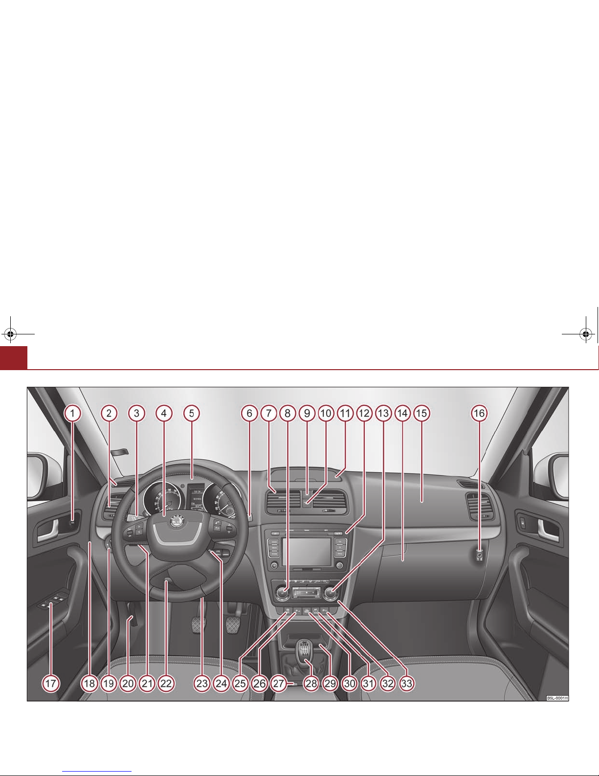
Fig. 1 Certain items of equipment shown in the illustration are only fitted to particular model versions or are optional items of equipment.
s2ak.b.book Page 8 Monday, April 6, 2009 2:13 PM
Cockpit 9
Using the system Safety Driving Tips General Maintenance Breakdown assistance Technical Data
Cockpit
Overview
This overview will help you to quickly familiarise yourself with the
displays and the control elements.
Electric exterior mirror adjustment . . . . . . . . . . . . . . . . . . . . . . . . . . .
Air outlet vents . . . . . . . . . . . . . . . . . . . . . . . . . . . . . . . . . . . . . . . . . . . . .
Lever for the multi-functional switch:
− Turn signal light, headlight and parking light, headlight flasher
− Cruise control system* . . . . . . . . . . . . . . . . . . . . . . . . . . . . . . . . . . .
Steering wheel:
− with horn
− with driver airbag . . . . . . . . . . . . . . . . . . . . . . . . . . . . . . . . . . . . . . . .
− with pushbuttons for radio, navigation system and mobile
phone* . . . . . . . . . . . . . . . . . . . . . . . . . . . . . . . . . . . . . . . . . . . . . . . . .
Instrument cluster: Instruments and indicator lights . . . . . . . . . . .
Lever for the multi-functional switch:
− Multi-functional indicator . . . . . . . . . . . . . . . . . . . . . . . . . . . . . . . .
− Windshield wiper and wash system . . . . . . . . . . . . . . . . . . . . . . .
Air outlet vents . . . . . . . . . . . . . . . . . . . . . . . . . . . . . . . . . . . . . . . . . . . . .
Control dial for heating on the driver's seat* . . . . . . . . . . . . . . . . . .
Switch for hazard warning lights . . . . . . . . . . . . . . . . . . . . . . . . . . . . .
Indicator light for a switched off front seat passenger airbag . . .
Storage compartment on the dash panel* . . . . . . . . . . . . . . . . . . . .
Depending on equipment fitted:
− Radio*
− Navigation*
Control dial for heating on the front passenger seat* . . . . . . . . . .
Storage compartment on the front passenger side . . . . . . . . . . . .
Front passenger airbag . . . . . . . . . . . . . . . . . . . . . . . . . . . . . . . . . . . . .
Switch for the front passenger airbag (in front passenger storage
compartment) . . . . . . . . . . . . . . . . . . . . . . . . . . . . . . . . . . . . . . . . . . . . .
Electric power-operated window* . . . . . . . . . . . . . . . . . . . . . . . . . . .
Fuse box (on side of dash panel) . . . . . . . . . . . . . . . . . . . . . . . . . . . .
Light switch . . . . . . . . . . . . . . . . . . . . . . . . . . . . . . . . . . . . . . . . . . . . . . . .
Bonnet release lever . . . . . . . . . . . . . . . . . . . . . . . . . . . . . . . . . . . . . . .
Control dial for the instrument lighting and control dial for the head-
light beam range regulation . . . . . . . . . . . . . . . . . . . . . . . . . . . . . . . . .
Lever for adjusting the steering wheel . . . . . . . . . . . . . . . . . . . . . . .
Driver's knee airbag* . . . . . . . . . . . . . . . . . . . . . . . . . . . . . . . . . . . . . . .
Ignition lock . . . . . . . . . . . . . . . . . . . . . . . . . . . . . . . . . . . . . . . . . . . . . . .
Depending on equipment fitted:
− Switch for the ESP* . . . . . . . . . . . . . . . . . . . . . . . . . . . . . . . . . . . . . .
− Switch for TCS . . . . . . . . . . . . . . . . . . . . . . . . . . . . . . . . . . . . . . . . . . .
Front and rear parking aid* . . . . . . . . . . . . . . . . . . . . . . . . . . . . . . . . .
Central locking switch . . . . . . . . . . . . . . . . . . . . . . . . . . . . . . . . . . . . . .
Gearshift lever . . . . . . . . . . . . . . . . . . . . . . . . . . . . . . . . . . . . . . . . . . . . .
Storage compartment . . . . . . . . . . . . . . . . . . . . . . . . . . . . . . . . . . . . . .
Offroad* . . . . . . . . . . . . . . . . . . . . . . . . . . . . . . . . . . . . . . . . . . . . . . . . . .
Tyre inflation pressure-control system* . . . . . . . . . . . . . . . . . . . . . .
Park Assist* . . . . . . . . . . . . . . . . . . . . . . . . . . . . . . . . . . . . . . . . . . . . . . . .
Depending on equipment fitted:
− Operating controls for the heating . . . . . . . . . . . . . . . . . . . . . . . .
− Operating controls for Climatic* . . . . . . . . . . . . . . . . . . . . . . . . . .
− Operating controls for Climatronic* . . . . . . . . . . . . . . . . . . . . . . .
Note
• Equipment which is marked * is only standard on certain vehicle model
versions or only suppliable as optional equipment for certain models.
A
1
73
A
2
106
A
3
64
130
A
4
159
133
A
5
17
A
6
21
69
A
7
106
A
8
84
A
9
64
A
10
167
A
11
100
A
12
A
13
84
A
14
99
A
15
159
A
16
167
A
17
14
A
18
252
A
19
58
A
20
218
A
21
63, 63
A
22
11
A
23
162
A
24
121
A
25
177
179
A
26
125
A
27
46
A
28
123
A
29
101
A
30
185
A
31
183
A
32
127
A
33
107
109
113
s2ak.b.book Page 9 Monday, April 6, 2009 2:13 PM
Cockpit10
• Cars with factory-fitted radio or navigation system are supplied with separate
instructions for operating such equipment.
• The arrangement of the controls and switches on right-hand drive models may
differ to some extent from that shown on ⇒ page 8, fig. 1. The symbols on the
controls and switches are the same as for left-hand drive models.
s2ak.b.book Page 10 Monday, April 6, 2009 2:13 PM
The brief instruction 11
Using the system Safety Driving Tips General Maintenance Breakdown assistance Technical Data
The brief instruction
Basic functions and important information
Introduction
The chapter of the brief instruction is only used as a quick reference
of the most important operating elements of the vehicle. It is necessary to observe all the information which is contained in the
following chapters of the Owner's Manual.
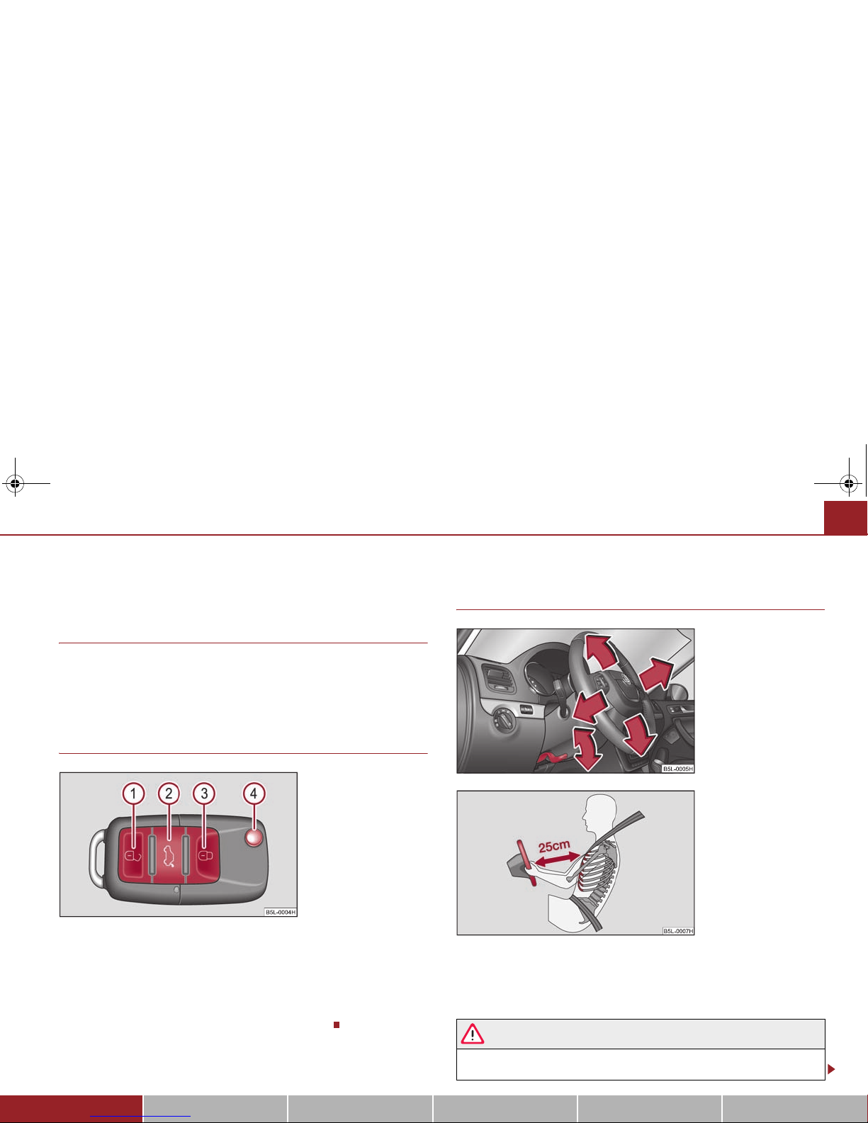
Unlocking and locking the vehicle
Unlocking the vehicle
Unlocking the boot lid
Locking the vehicle
Folding out/folding up of the key
Further information ⇒ page 49, “Unlocking and locking car”.
Setting steering wheel position
You can set the height and the forward/back position of the steering wheel to the
desired position.
Further information ⇒ page 120, “Setting steering wheel position”.
WARNING
• Adjust the steering wheel so that the distance between the steering
wheel and your chest is at least 25 cm ⇒ fig. 4. Not maintaining this
Fig. 2 Remote control key
A1A2A3A
4
Fig. 3 Adjustable steering
wheel: Lever on the steering
column
Fig. 4 The correct distance of
the driver from the steering
wheel
s2ak.b.book Page 11 Monday, April 6, 2009 2:13 PM

The brief instruction12
minimum distance will mean that the airbag syste m wil l not b e abl e to pr operly protect you - hazard!
• You must not adjust the steering wheel when the vehicle is moving!
• Fo r sa fet y re aso ns t he lev er m ust alw ays be fir mly pus hed up t o a voi d th e
steering wheel altering its position unintentionally when driving - risk of
accident!
Seat belt height adjuster
– Move the height adjuster in the desired direction up or down ⇒ fig. 5.
– Then pull firmly on the belt to ensure that the seat belt height adjuster
has correctly locked in place.
Further information ⇒ page 155, “Seat belt height adjuster”.
WARNING
Adjust the height of the belt in such a way that the shoulder part of the belt
is positioned approximately across the middle of your shoulder - on no
account across your neck!
Adjusting the front seats
Adjusting a seat in a forward/back direction
Adjusting height of seat
Adjust the angle of the seat backrest
Adjusting lumbar support*
Further information ⇒ page 75, “Adjusting the front seats”.
WARNING
Only adjust the driver seat when the vehicle is stationary - risk of injury!
WARNIN G (continued )
Fig. 5 Front seat: Seat belt
height adjuster
Fig. 6 Controls at seat
A1A2A3A
4
s2ak.b.book Page 12 Monday, April 6, 2009 2:13 PM

The brief instruction 13
Using the system Safety Driving Tips General Maintenance Breakdown assistance Technical Data
Electric exterior mirror adjustment*
Further information ⇒ page 73, “Exterior mirror”.
Switching lights on and off
Further information ⇒ page 58, “Switching lights on and off ”.
Heating of the external mirror*
Adjusting left and right exterior mirrors simultaneously
Adjusting the right-hand exterior mirror
Switching off operating control
Fig. 7 Inner part of door:
Rotary knob
Automatic light control*
Switching off all lights/daylight driving lights
Switching on side lights
Switching on the low beam and main beam
Fog lights*
Rear fog light
Fig. 8 Dash panel: Light
switch
s2ak.b.book Page 13 Monday, April 6, 2009 2:13 PM
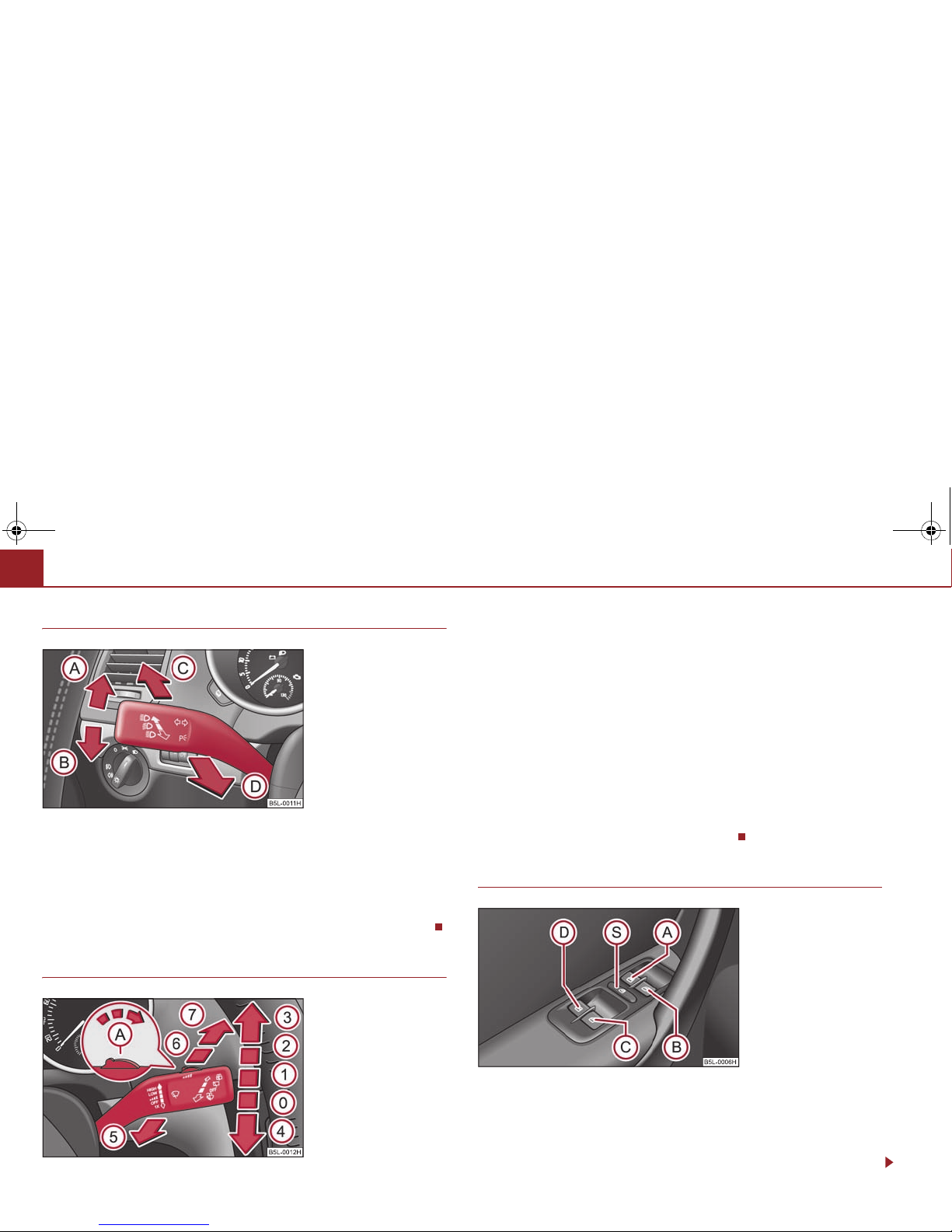
The brief instruction14
Turn signal and main beam lever
Turn signal light right
Turn signal light left
Switching over between low beam and main beam lights
Headlight flasher
Further information ⇒ page 64, “The turn signal and main beam lever ”.
Windscreen wiper lever
Intermittent switch, sensitivity setting rain sensor*
Wipers off
Intermittent wipe
Slow wipe
Fast wipe
one time wipe
Automatic wipe/wash
Rear window wiper
Intermittent wipe - every 6 seconds
Automatic wipe/wash
Further information ⇒ page 69, “Windshield wiper”.
Power windows*
Button for the power window in the driver's door
Button for the power window in the front passenger's door
Button for the power window in the rear door on the right*
Button for the power window in the rear door on the left*
Fig. 9 Turn signal and main
beam lever
AAABACA
D
Fig. 10 Windscreen wiper
lever
AAA0A1A2A3A4A5A6A
7
Fig. 11 Buttons on the
driver's door
AAABACA
D
s2ak.b.book Page 14 Monday, April 6, 2009 2:13 PM
The brief instruction 15
Using the system Safety Driving Tips General Maintenance Breakdown assistance Technical Data
Safety pushbutton*
Further information ⇒ page 52, “Power windows*”.
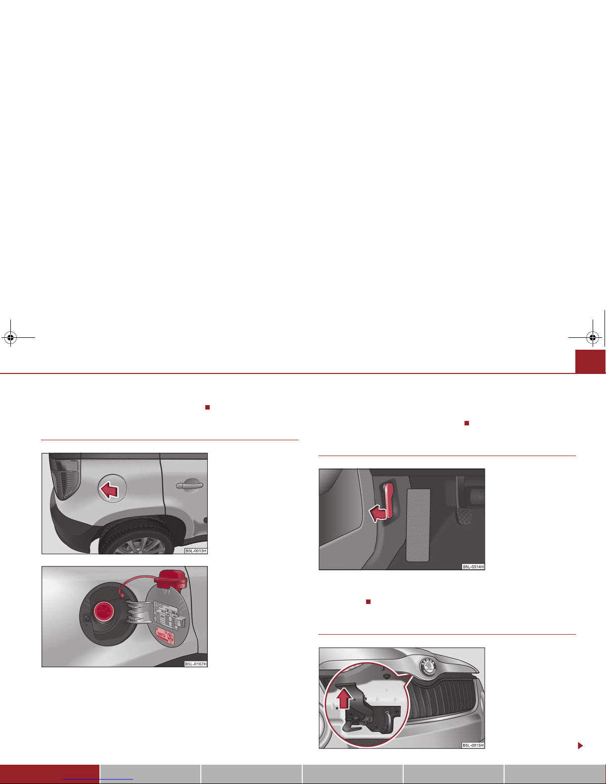
Refuelling
– Press onto the left side of the fuel filler flap ⇒ fig. 12.
– The fuel filler cap on the fuel filler tube must be unlocked to the left
using the vehicle key (only valid for vehicles which do not have automatic unlocking of the fuel filler flap).
– Unscrew the fuel filler cap anti-clockwise and place the fuel filler cap
from above on the fuel filler flap ⇒ fig. 13.
Further information ⇒ page 216, “Refuelling”.
Bonnet remote release
– Pull the unlocking lever below the dash panel on the driver's side
⇒ fig. 14.
Opening the bonnet
A
S
Fig. 12 Right rear side of the
vehicle: Fuel filler flap
Fig. 13 Fuel filler flap with
cap unscrewed
Fig. 14 Bonnet release lever
Fig. 15 Radiator grille:
Locki ng lever
s2ak.b.book Page 15 Monday, April 6, 2009 2:13 PM
The brief instruction16
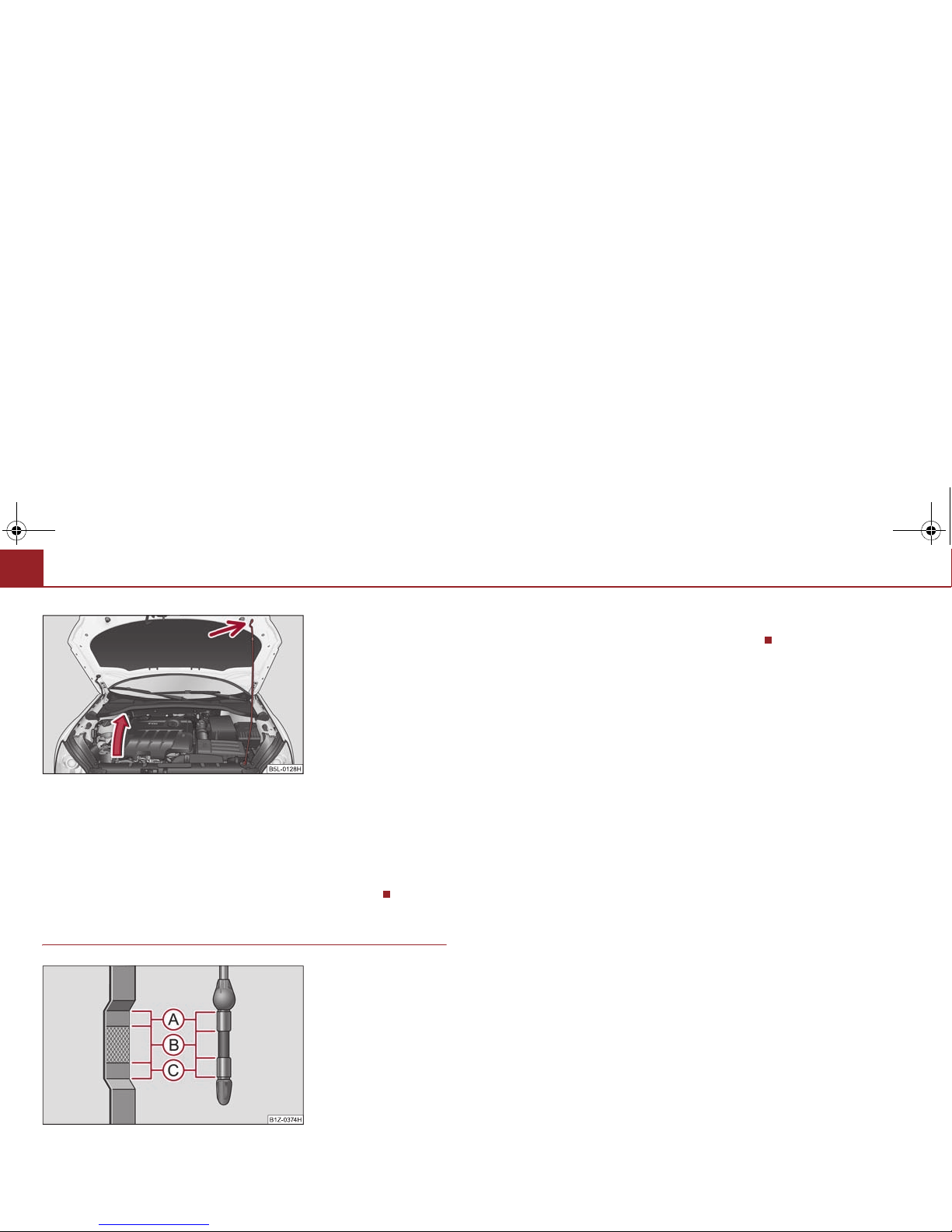
– Pulling on the locking lever ⇒ page 15, fig. 15 will unlock the bonnet
fully.
– Take the bonnet support out of its holder and set it in the opening
designed for it ⇒ fig. 16.
Further information ⇒ page 218, “Opening and closing the bonnet.”.
Inspecting the engine oil level
Engine oil must not be refilled.
Engine oil can be refilled.
Engine oil must be refilled.
Further information ⇒ page 221, “Check engine oil level”.
Fig. 16 Securing the bonnet
with the bonnet support
Fig. 17 Dipstick
AAABA
C
s2ak.b.book Page 16 Monday, April 6, 2009 2:13 PM
Instruments and Indicator/Warning Lights 17
Using the system Safety Driving Tips General Maintenance Breakdown assistance Technical Data
Instruments and Indicator/Warning Lights
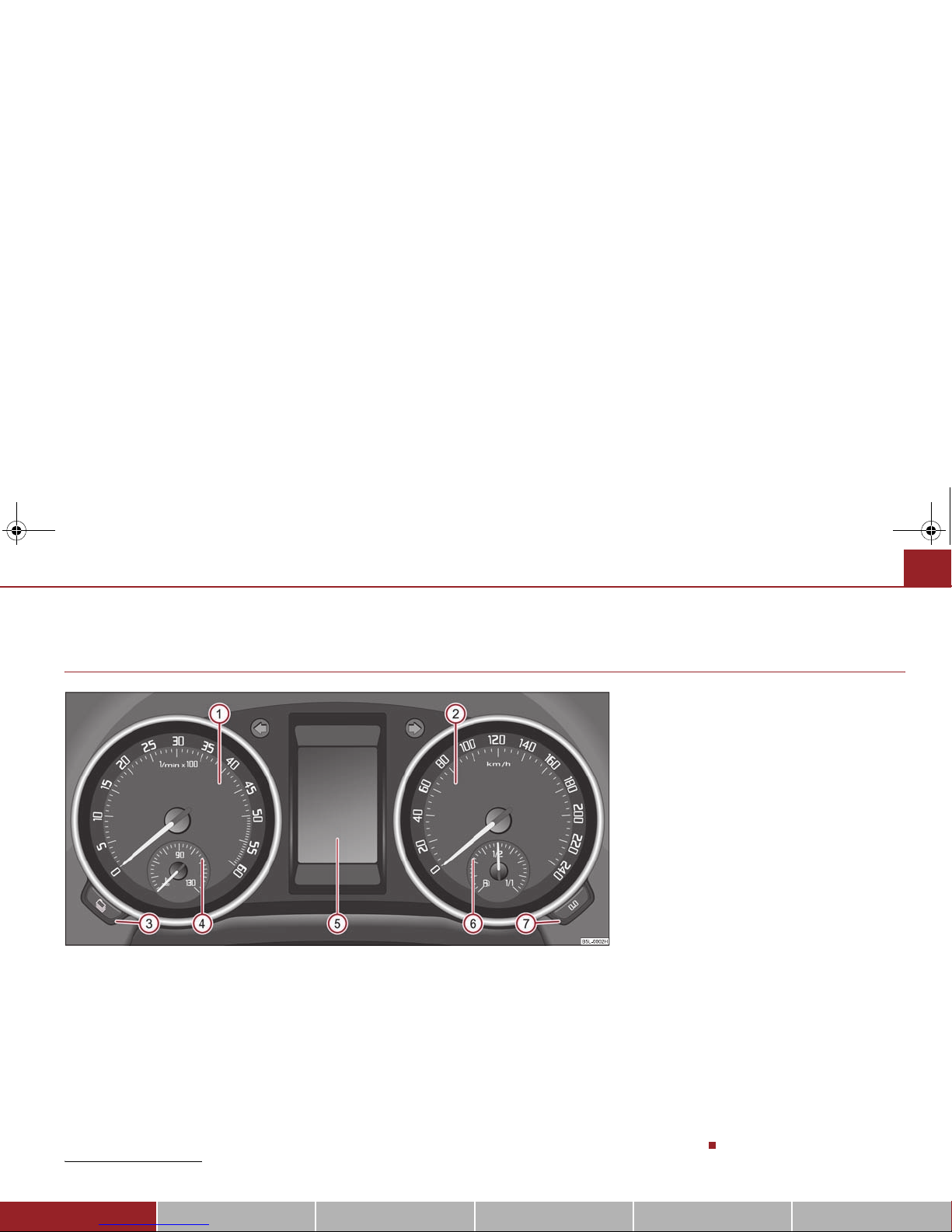
General view of the instrument cluster
Engine revolutions counter ⇒ page 18
Speedometer ⇒ page 18
Button for display mode:
− Set hours / minutes
− Activating / deactivating the second speed in mph or km/h*
− Service interval - Display of the remaining number of days or miles to the
next Inspection Service / Reset*
1)
Coolant temperature gauge ⇒ page 18
Display
− with counter for distance driven ⇒ page 19
− with Service Interval Display ⇒ page 20
− with digital clock ⇒ page 21
− with Multi-functional indicator* ⇒ page 21
− with Information display* ⇒ page 26
Fuel gauge ⇒ page 18
Button for:
− Reset trip counter for distance driven
− Resetting Service Interval Display
− Set hours / minutes
− Activate / deactivate display mode
Fig. 18 Instrument cluster
1)
Valid for countries where the values are indicated in British measuring units.
A1A
2
A3A
4
A5A
6
A
7
s2ak.b.book Page 17 Monday, April 6, 2009 2:13 PM
Instruments and Indicator/Warning Lights18
Engine revolutions counter
The red zone of the rev counter scale ⇒ page 17, fig. 18 indicates the range in
which the engine control unit begins to limit the engine speed. The engine control
unit restricts the engine speed to a steady limit value.
Before reaching the red zone of the rev counter scale, shift up into the next higher
gear.
Avoid high engine speeds during the driving time and before the engine has been
warmed up to operating temperature ⇒ page 187.
For the sake of the environment
Shifting up early helps you save fuel and reduce the operating noise of your
vehicle.
Speedometer
Warning against excessive speeds*
An acoustic warning signal will sound when the vehicle speed exceeds 120 kilometres per hour. The acoustic warning signal will switch off again when the vehicle
speed goes below this speed limit.
Note
This function is only valid for some countries.
Coolant temperature gauge
The coolant temperature gauge ⇒ page 17, fig. 18 operates only when the ignition is switched on.
In order to avoid any damage to the engine, please pay attention to the following
notes regarding the temperature ranges:
Cold range
If the pointer is in the left-hand area of the scale it means that the engine has not
yet reached its operating temperature. Avoid running at high engine speeds, at full
throttle and at severe engine loads.
The operating range
The engine has reached its operating temperature as soon as the pointer moves
into the mid-range of the scale. The pointer may also move further to the right at
high engine loads and high outside temperatures. This is not critical provided the
warning symbol in the instrument cluster does not flash.
If the symbol in the instrument cluster flashes it means that either the coolant
temperature is too high or the coolant level is too low. Observe the guidelines
⇒ page 37, “Coolant temperature/ Coolant quantity ”.
WARNING
Pay attention to the warning notes ⇒ page 219, “Working in the engine
compartment” before opening the bonnet and inspecting the coolant level.
Caution
Additional headlights and other attached components in front of the fresh air inlet
impair the cooling efficiency of the coolant. There is then a risk of the engine overheating at high outside temperatures and high engine loads!
Fuel gauge
The fuel gauge ⇒ page 17, fig. 18 only operates when the ignition is switched
on.
The fuel tank has a capacity of about 60 litres. The warning symbol in the instrument cluster lights up when the pointer reaches the reserve marking. There are now
about 10.5 litres of fuel remaining in the tank. This symbol is a reminder for you,
that you must refuel.
A
1
A4A
6
s2ak.b.book Page 18 Monday, April 6, 2009 2:13 PM
Instruments and Indicator/Warning Lights 19
Using the system Safety Driving Tips General Maintenance Breakdown assistance Technical Data
The following will be displayed in the information display*:
Please refuel!
An audible signal sounds as an additional warning signal.
Caution
Never run the fuel tank completely empty! The irregular supply of the fuel system
can lead to irregular running of the engine. Unburnt fuel may get into the exhaust
system and damage the catalytic converter.
Note
After filling up, it can occur that during dynamic driving (e.g. numerous curves,
braking, driving downhill and climbing a steep hill) the fuel gauge indicates approx.
a fraction less. When stopping or during less dynamic driving, the correct fuel
supply quantity is indicated. This effect is not a fault.
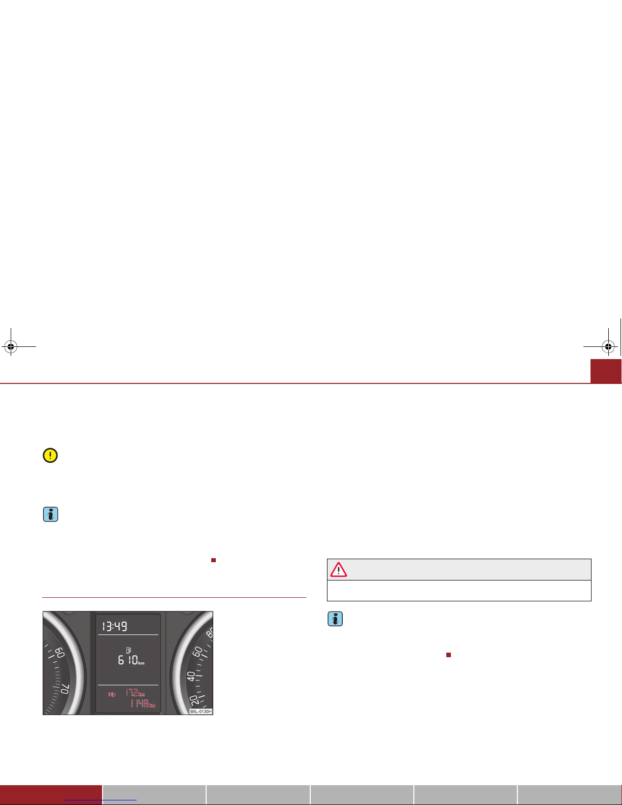
Counter for distance driven
The distance which you have driven with your vehicle is shown in kilometres (km).
In some countries the measuring unit “mile” is used.
Reset button
If you hold the reset button ⇒ page 17, fig. 18 pressed for about 1 second, the
trip counter is set back to zero.
Trip counter for distance driven
The trip counter indicates the distance which you have driven ⇒ fig. 19 since this
counter was last reset - in steps of 100 metres or 1/10 of a mile.
Counter for distance driven
The counter for distance driven ⇒ fig. 19 indicates the total distance in kilometers
or miles which the vehicle has driven.
Fault disp lay
If there is a fault in the instrument cluster, a constant text will appear in the display
Error. Have the fault rectified as soon as possible by a specialist workshop.
WARNING
Never seek to adjust the trip counter for distance driven while driving for
safety reasons!
Note
If vehicles which are fitted with the information display* the display of the second
speed is activated in mph or km/h, this driving speed is indicated instead of the
counter for the total distance driven.
Fig. 19 Display: Counter for
distance driven
A
7
s2ak.b.book Page 19 Monday, April 6, 2009 2:13 PM
Instruments and Indicator/Warning Lights20
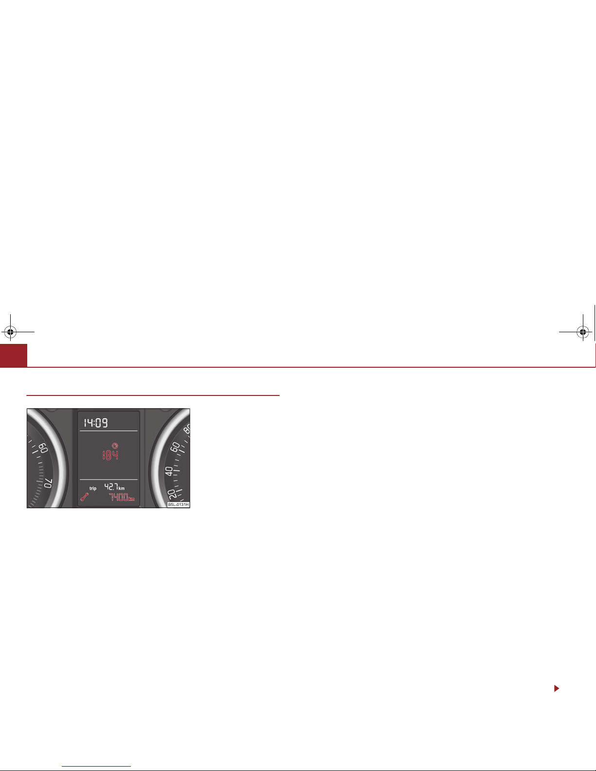
Service Interval Display
Depending on the equipment installed in the vehicle, the text can differ on the
display.
Service Interval Display
Before the next service interval a key symbol and the remaining kilometers are
indicated after switching on the ignition ⇒ fig. 20. At the same time, a display
appears regarding the remaining days until the next service interval.
The following will be displayed in the information display*:
Service in ... km or... days
The kilometre indicator or the days indicator reduces in steps of 100 km. or days
until the service due date is reached.
A flashing key symbol and the text Service appears in the display for 20 seconds
as soon as the due date for the service is reached.
The following will be displayed in the information display*:
Service now!
Display regarding the distance and days until the following service interval
You can use the button to display the remaining distance driven and the days
until the next service interval ⇒ page 17.
A key symbol and a display regarding the remaining kilometers appear for 10
second in the display. At the same time, a display appears regarding the remaining
days until the next service interval.
On vehicles which are equipped with information display*, you can call up this
information in the following menu on ⇒ page 27:
SETUP (Settings)
Service Interval (Service)
Info
The following will be displayed in the information display* for 10 seconds:
Service in ... km or... days
Resetting Service Interval Display
It is only possible to reset the Service Interval Display, if a service message or at least
a pre-warning is shown on the display of the instrument cluster.
We recommend having this resetting performed by a specialist garage.
The specialist garage:
• resets the memory of the display after the appropriate inspection;
• makes an entry in the Service schedule;
• affix the sticker with the entry of the following service interval to the side of the
dash panel on the driver's side.
Reset the service interval displays by using the reset button ⇒ page 17 on the
trip counter.
On vehicles which are equipped with information display*, you can call up this
information in the following menu on ⇒ page 27:
SETTINGS (SETTINGS)
Service Interval (Service)
Reset
Fig. 20 Service Interval
Display: Note
A3A
7
s2ak.b.book Page 20 Monday, April 6, 2009 2:13 PM

Instruments and Indicator/Warning Lights 21
Using the system Safety Driving Tips General Maintenance Breakdown assistance Technical Data
Caution
We recommend that you do not reset the Service Interval Display yourself otherwise this can result in the service interval display being incorrectly set, which may
also result in problems with operation of your vehicle.
Note
• Never reset the display between service intervals otherwise this may result in
incorrect readouts.
• information is retained in the Service Interval Display also after the battery of
the vehicle is disconnected.
• If the instrument cluster is exchanged after a repair, the correct values must be
entered in the counter for the Service Interval Display. This work is carried out by a
specialist garage.
• The data displayed is the same after resetting the display with flexible service
intervals (QG1) using the reset button as that for a vehicle with fixed service intervals (QG2). We therefore recommend having the Service Interval Display reset only
by a specialist garage which is familiar with the procedure for resetting the display
with a vehicle system tester.
• Please refer to the brochure Service schedule for extensive information about
the service intervals.
Digital clock
The time is set with the buttons and ⇒ page 17, fig. 18.
Select the display which you wish to change with the button and carry out the
change with the button .
On vehicles which are fitted out with the information display*, it is possible to set
the time in the menu Time ⇒ page 30.
WARNING
The clock should not be adjusted while driving for safety reasons but only
when the vehicle is stationary!
Multi-functional indicator (onboard computer)
Introduction
The multi-functional indicator appears in the display ⇒ page 22, fig. 21 or in the
information display ⇒ page 26 depending on the equipment fitted to your vehicle.
The multi-functional indicator offers you a range of useful information.
On vehicles which are fitted out with information display*, it is possible to switch
off the display of some information.
Caution
Pull out the ignition key while having contact with the display (for example when
cleaning) in order to prevent any damage.
A3A7A3A
7
The outside temperature ⇒ page 24
Driving time ⇒ page 24
Current fuel consumption ⇒ page 24
Average fuel consumption ⇒ page 24
Range ⇒ page 25
Distance driven ⇒ page 25
Average speed ⇒ page 25
Current speed* ⇒ page 25
Warning against excessive speeds* ⇒ page 25
s2ak.b.book Page 21 Monday, April 6, 2009 2:13 PM

Instruments and Indicator/Warning Lights22
Note
• In certain national versions the displays appear in the Imperial system of meas-
ures.
• If the display of the second speed is activated in mph, the current speed* is not
indicated in km/h on the display.
Memory
The multi-functional indicator is equipped with two automatic memories. The
selected memory is displayed in the middle of the display field ⇒ fig. 21.
The data of the single-trip memory (memory 1) is shown if a 1 appears in the
display. A 2 shown in the display means that data relates to the total distance
memory (memory 2).
Switching over the memory with the help of the button ⇒ fig. 22 on the windscreen wiper lever or with the help of the button on the multifunction steering
wheel* ⇒ page 23.
Single-trip memory (memory 1)
The single-trip memory collates the driving information from the moment the ignition is switched on until it is switched off. New data will also flow into the calculation of the current driving information if the trip is continued within 2 hours after
switching off the ignition. The memory will be is automatically erased, on the other
hand, if the trip is interrupted for more than 2 hours.
Total-trip memory (memory 2)
The total distance driven memory gathers data from any number of individual journeys up to a total of 99 hours and 59 minutes driving or 9.999 kilometres driven.
The memory is deleted when either of these limits is reached and the calculation
starts from anew.
The total-trip memory will not, contrary to the single-trip memory, be deleted after
a period of interruption of driving of 2 hours.
Note
All information in the memory 1 and 2 is erased if the battery of the vehicle is
disconnected.
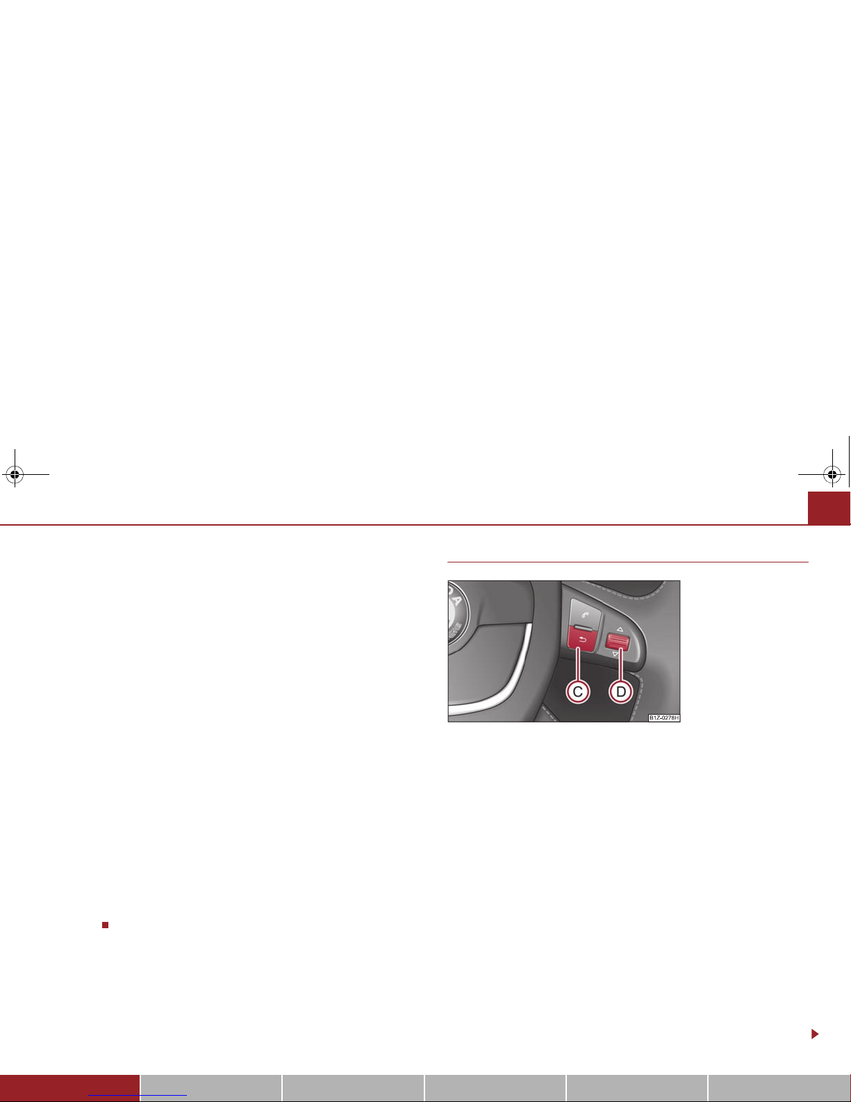
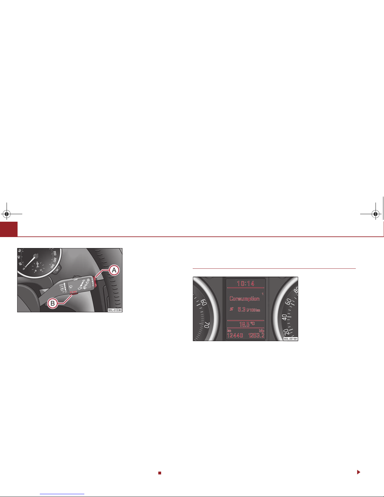
Operating with the buttons on the windshield wiper lever
The rocker switch and the button are located in the grip of the
window wiper lever ⇒ fig. 22.
Fig. 21 Multi-functional
indicator
ABA
D
Fig. 22 Multi-functional
indicator: Control elements
AAA
B
s2ak.b.book Page 22 Monday, April 6, 2009 2:13 PM
Instruments and Indicator/Warning Lights 23
Using the system Safety Driving Tips General Maintenance Breakdown assistance Technical Data
Selecting the memory
– Short-term pressing of the button allows to select the desired
memory.
Selecting the functions
– Press the top or bottom rocker switch for longer than 0.5 seconds.
In this way, call up in sequence the individual functions of the multifunctional indicator.
Setting function to zero
– Select the memory you want.
– Press button for more than 1 second.
The following readouts of the selected memory will be set to zero by button :
• average fuel consumption,
• distance driven,
• average speed,
• Driving time.
You can only operate the multi-functional indicator when the ignition is switched
on. After the ignition is switched on, the function displayed is the one which you last
selected before switching off the ignition.
On vehicles fitted with the multifunction steering wheel*, the buttons and
have been replaced with the rotary control on the multifunction steering wheel
⇒ fig. 23.
Operating with the buttons on the multifunction steering wheel*
Switching over and resetting is performed with the handwheel
⇒ fig. 23.
Selecting the memory
– Short-term pressing of the button allows to select the desired
memory.
Selecting the functions
– By pressing the button , you can call up the menu of the multi-func-
tional indicator.
– Turn the handwheel upwards or downwards. In this way, call up in
sequence the individual functions of the multi-functional indicator.
– Short-term pressing of the button allows to select the highlighted
function.
Setting function to zero
– Select the memory you want.
– Press the button for more than 1 second.
ABA
A
A
B
A
B
AAA
B
Fig. 23 Multi-functional
indicator: Operating with the
buttons on the multifunction
steering wheel
ADA
D
ACA
D
A
D
A
D
s2ak.b.book Page 23 Monday, April 6, 2009 2:13 PM
Instruments and Indicator/Warning Lights24
The following readouts of the selected memory will be set to zero with the button
:
• average fuel consumption,
• distance driven,
• average speed,
• Driving time.
You can only operate the multi-functional indicator when the ignition is switched
on. After the ignition is switched on, the function displayed is the one which you last
selected before switching off the ignition.
Outside temperature
The outside temperature appears in the display when the ignition is switched on.
If the outside temperature drops below +4°C, a snow flake symbol (warning signal
for ice on the road) appears in front of the temperature indicator and flashes for 10
seconds, then remains displayed together with the outside temperature ⇒ fig. 24.
At the same time an audible signal sounds. After pressing the rocker switch at
the windshield wiper lever ⇒ page 22, fig. 22 or the button at the multifunction
steering wheel ⇒ page 23, fig. 23, the function shown last is indicated.
WARNING
Do not only rely upon the information given on the outside temperature
display that there is no ice on the road. Please note that black ice may also be
present on the road surface even at temperatures around +4 °C - warning,
drive with care!
Driving time
The driving time which has elapsed since the memory was last erased, appears in
the display. If you wish to measure the driving time as of a particular time, you must
set the memory to zero at this moment in time by pressing the button on the
windshield wiper lever ⇒ page 22, fig. 22 or the handwheel on the multifunction steering wheel* ⇒ page 23, fig. 23 for longer than 1 second.
The maximum distance indicated in both memories is 99 hours and 59 minutes.
The indicator is set back to null if this period is exceeded.
Current consumption
The current fuel consumption level is shown in the display in litres/100 km. This
information can help you to adapt your style of driving to the fuel consumption you
wish to achieve.
The display appears in litres/hour if the vehicle is stationary or driving at a low
speed.
The indicated value will be updated every 0,5 seconds while you are driving.
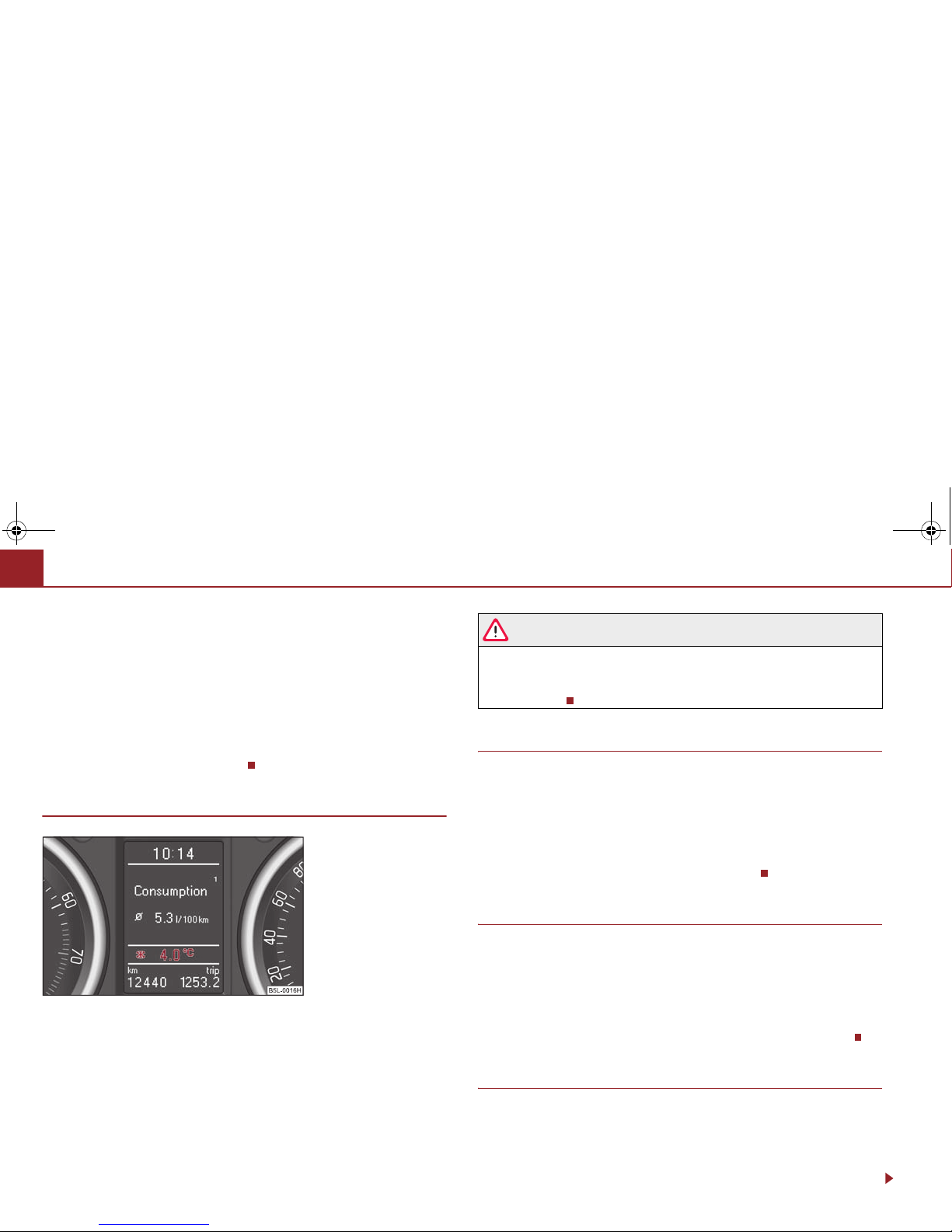
Average fuel consumption
The average fuel consumption since the memory was last erased is shown in the
display in litres/100 km ⇒ page 22, fig. 21. This information can help you to adapt
your style of driving to the fuel consumption you wish to achieve.
If yo u wi sh to d et erm in e t he a ve rag e fu el co nsu mp tio n o ver a c er tai n p er iod of tim e
you must set the memory to zero at the start of the measurement using the button
A
D
Fig. 24 The outside temperature
A
A
A
C
ABA
D
s2ak.b.book Page 24 Monday, April 6, 2009 2:13 PM
Instruments and Indicator/Warning Lights 25
Using the system Safety Driving Tips General Maintenance Breakdown assistance Technical Data
on the windshield wiper lever ⇒ page 22, fig. 22 or with the handwheel on
the multifunction steering wheel* ⇒ page 23, fig. 23. A zero appears in the display
for the first 100 m you drive after erasing the memory.
The indicated value will be updated every 5 seconds while you are driving.
Note
The amount of fuel consumed will not be indicated.
Range
The estimated range in kilometres is shown on the display. It indicates the distance
you can still drive with your vehicle based on the present level of fuel in the tank for
the same style of driving.
The readout is shown in steps of 10 km. After lighting up of the indicator light for the
fuel reserve the display is shown in steps of 5 km.
The fuel consumption for the last 50 km is taken as a basis for calculating the range.
If you drive in a more economical manner from this moment on, the range will be
increased accordingly.
If the memory is set to zero (after disconnecting the battery), the fuel consumption
of 10 ltr./100 km is calculated for the range; afterwards the value is adapted accordingly to the style of driving.
Distance driven
The distance driven since the memory was last erased appears in the display
⇒ page 22. If you wish to measure the distance driven of a particular time, you
must set the memory to zero at this moment in time by pressing the button on
the windshield wiper lever ⇒ page 22, fig. 22 or the handwheel on the multifunction steering wheel* ⇒ page 23, fig. 23.
The maximum distance indicated in both switch positions is 9 999 km. The indicator
is set back to null if this period is exceeded.
Average speed
The average speed since the memory was last erased is shown in the display in
km/hour ⇒ page 22. If you wish to determine the average vehicle speed over a
certain period of time you must set the memory to zero at the start of the measurement using the button on the windshield wiper lever ⇒ page 22, fig. 22 or with
the handwheel on the multifunction steering wheel* ⇒ page 23, fig. 23.
A zero appears in the display for the first 100 m you drive after erasing the memory.
The indicated value will be updated every 5 seconds while you are driving.
Current speed*
The current speed which is identical to the display of the speedometer, is indicated
on the display ⇒ page 17, fig. 18.
Warning against excessive speeds*
ABA
D
A
B
ADA
B
A
D
A
2
Fig. 25 Warning against
excessive speeds
s2ak.b.book Page 25 Monday, April 6, 2009 2:13 PM
Instruments and Indicator/Warning Lights26
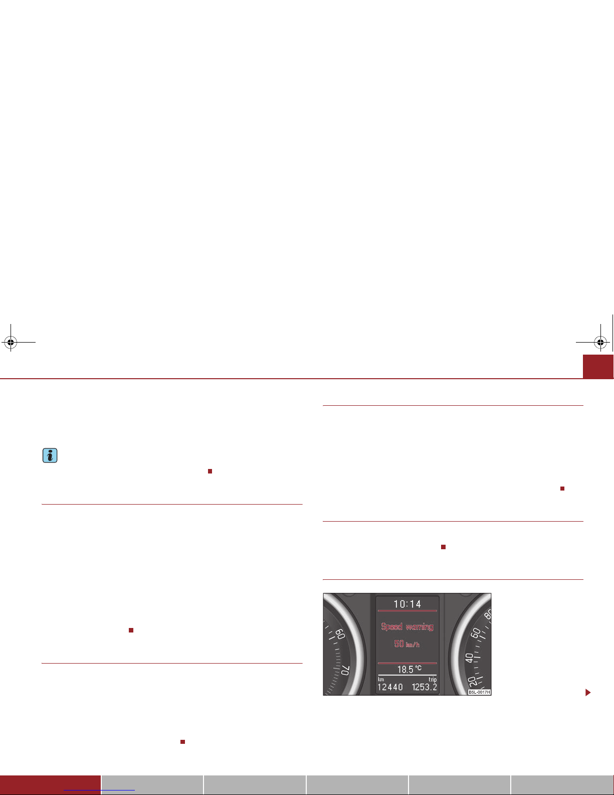
Warning against excessive speeds
This function enables you to set a speed limit, e.g. if you drive in town. A text in the
display is intended to draw your attention to the fact that you have exceeded the set
speed limit.
You can set the desired speed limit as follows:
• Select the menu point Speed warning --- km/h (warning at --- km/h)..
• Drive e.°g at a speed of 50 km/h.
• Press the button on the windshield wiper lever ⇒ fig. 26 or the handwheel
on the multifunction steering wheel* ⇒ page 23, fig. 23. Speed warning
50 km/h (warning at 50 km/h) is displayed in the information display*
⇒ page 25, fig. 25. You can increase or reduce this value with the button on the
windshield wiper lever or by turning the handwheel on the multifunction
steering wheel*.
• The value is stored by repeated pressing of the button on the windshield
wiper lever or the handwheel on the multifunction steering wheel*.
If you now exceed the set speed limit, Speed 50 km/h exceeded will be shown in
the display. This message is indicated for as long as the speed is reduced below the
set limit or switch off the message by pressing the button on the windshield
wiper lever ⇒ fig. 26 or the handwheel on the multifunction steering wheel*
⇒ page 23, fig. 23.
An audible signal sounds as an additional warning signal.
The set speed limit remains stored even after switching off the ignition.
Information display*
Introduction
The information display provides you with information in a convenient way
concerning the current operating state of your vehicle. The information display
also provides you with data (depending on the equipment installed in the vehicle)
relating to the radio, multi-functional indicator, mobile phone and navigation
system.
Certain functions and operating conditions are always being checked on the
vehicle when the ignition is switched on and also while driving.
Functional faults, if required repair work and other information are indicated by red
symbols ⇒ page 29 and yellow symbols ⇒ page 29.
Lighting up of certain symbols is combined with an acoustic warning signal.
Information and texts giving warnings are also shown in the display ⇒ page 32.
The display of text is possible in the following languages:
Czech, English, German, French, Italian, Spanish, Portuguese, Russian and
Chinese.
You can select the desired language in the setting menu.
The following information can be shown in the display (depending on the equipment installed on the vehicle):
Fig. 26 Multi-functional
indicator: Control elements
A
B
A
D
A
A
ADA
B
A
D
A
B
A
D
Fig. 27 Instrument cluster:
Information display
s2ak.b.book Page 26 Monday, April 6, 2009 2:13 PM
Instruments and Indicator/Warning Lights 27
Using the system Safety Driving Tips General Maintenance Breakdown assistance Technical Data
Caution
Pull out the ignition key while having contact with the display (for example when
cleaning) in order to prevent any damage.
Main menu
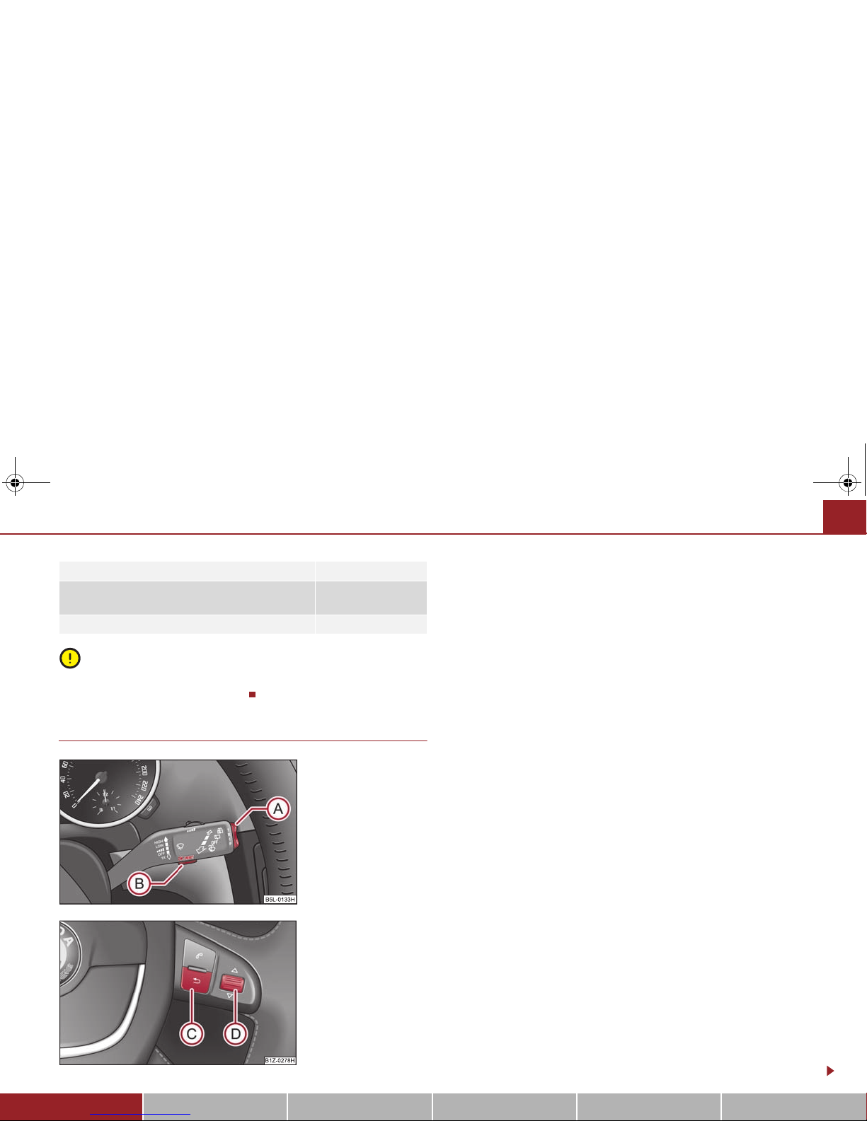
Operating with the buttons on the windshield wiper lever
– You can activate the MAIN MENU by pressing the rocker switch
⇒ fig. 28 for more than 1 second.
– You can select the menu through the rocker switch . When the
pushbutton is briefly pressed, the information you have selected is
displayed.
Operating with the buttons on the multifunction steering wheel*
– You can activate the MAIN MENU by pressing the button
⇒ fig. 29.
– You can select the individual menus by pressing the handwheel .
After briefly pressing the handwheel , the desired menu is indicated.
– After briefly pressing the button you can achieve a higher level, by
pressing the button for longer than 1 second, you can call up the
MAIN MENU.
You can select the following information (depending on the equipment installed on
the vehicle):
MFD (Onboard computer) ⇒ page 21
Audio*
Navigation*
Phone* ⇒ page 135
Aux. Heating (auxiliary heating)* ⇒ page 117
Assistant* ⇒ page 60
Vehicl e status ⇒ page 28
Setup ⇒ page 30
The menu point Audio is only displayed when the Radio* is switched on.
The menu point Navigation is only displayed when the Navigation system* is
switched on.
Main menu ⇒ page 27
Door, luggage compartment door and bonnet ajar
warning
⇒ page 28
Service Interval Display ⇒ page 20
Fig. 28 Information display:
Controls on the windshield
wiper lever
Fig. 29 Information display:
Controls on the multifunction steering wheel
A
A
AAABACADA
D
ACA
C
s2ak.b.book Page 27 Monday, April 6, 2009 2:13 PM
Instruments and Indicator/Warning Lights28
The menu point Aux. Heating is only then displayed, if the vehicle is fitted with
auxiliary heating*.
The menu point Assistant is only then displayed, if the vehicle is fitted with
cornering lights*.
Note
• If warning messages are shown in the information display ⇒ page 28
⇒ page 28, these messages can be confirmed with the button on the wind-
shield wiper lever or with the button on the multifunction steering wheel in
order to call up the main menu.
• If you do not activate the information display at that moment, the menu shifts
to one level higher every 10 seconds.
• The operation of the radio* or the navigation system* is described in separate
operating instructions to be found in the on-board literature.
Door, luggage compartment door and bonnet ajar warning
The door, luggage compartment and bonnet ajar warning lights up if at least one
door, the luggage compartment or bonnet are not closed. The symbol indicates
which door is still open or whether the luggage compartment door or bonnet is not
closed ⇒ fig. 30.
The symbol goes out as soon as the doors, luggage compartment door and bonnet
are completely closed.
A warning signal sounds if the car is driven at a speed of more than 6km/hour and
if the engine or the luggage compartment door is open.
Auto Check Control*
Car state
The Auto Check Control carries out a check of certain functions and vehicle components. The check is performed constantly when the ignition is switched on, both
when the vehicle is stationary, as well as when driving.
Some operational faults, urgent repairs, service work or other information appear
in the display of the instrument cluster. The displays are shown with a red or yellow
light symbol depending on the priority of the message.
The red symbols indicate danger (priority 1) while the yellow symbols indicate a
warning (priortity 2). Information for the driver may also appear in addition to the
symbols ⇒ page 32.
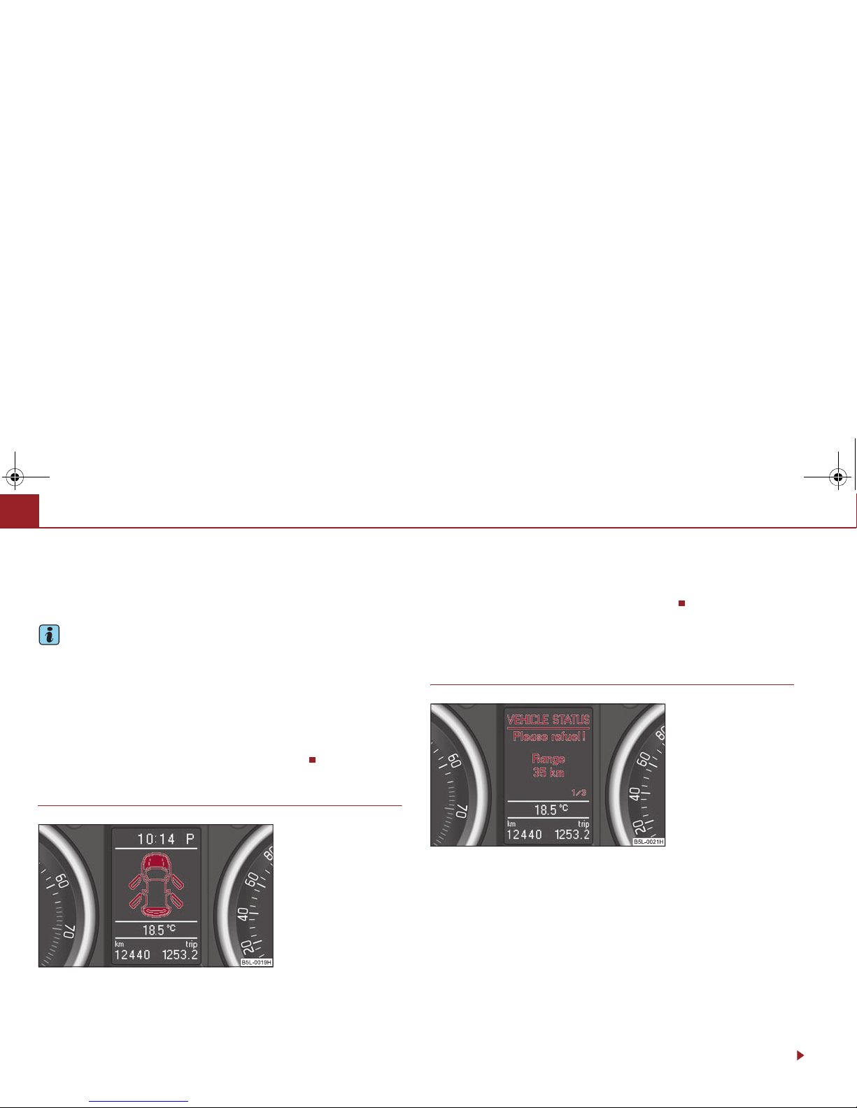
There is at least one error message when the term Veh icle s tatu s is displayed in the
menu. After selecting this menu the first of the error messages is displayed. Several
error messages are shown on the display under the message e.°g. 1/3 ⇒ fig. 31.
This indicates that the first of a total of three error messages is displayed. The
ABA
D
Fig. 30 Information display:
Door warning
Fig. 31 Information display:
Display of operational fault
s2ak.b.book Page 28 Monday, April 6, 2009 2:13 PM
Instruments and Indicator/Warning Lights 29
Using the system Safety Driving Tips General Maintenance Breakdown assistance Technical Data
respective messages are displayed one after the other in an interval of 5 seconds.
Check as soon as possible the displayed error messages.
As long as the operational faults are not rectified, the symbols are always indicated
again. After the first display, the symbols are indicated without information for the
driver.
If a fault occurs, a warning signal will also sound in addition to the symbol and text
in the display:
• Priority 1 - three warning signals
• Priority 2 - one warning signal
Red symbols
A red symbol signals danger.
– Bring the vehicle to a stop.
– Switch the engine off.
– Investigate the function indicated.
– Obtain professional assistance.
Meaning of the red symbols:
Three successive warning signals will sound if a red symbol appears.
Yellow symbols
A yellow symbol signals a warning.
Check the relevant function as soon as possible.
The meaning of the yellow symbols:
One warning signal will sound if a yellow symbol appears.
If several operational faults of priority 2 exist, the symbols appear one after the
other and are each illuminated for about 5 seconds.
Fig. 32 Information display:
Oil pressure is low
Engine oil pressure too low ⇒ page 36
Check engine oil level,
engine oil sensor faulty
⇒ page 221
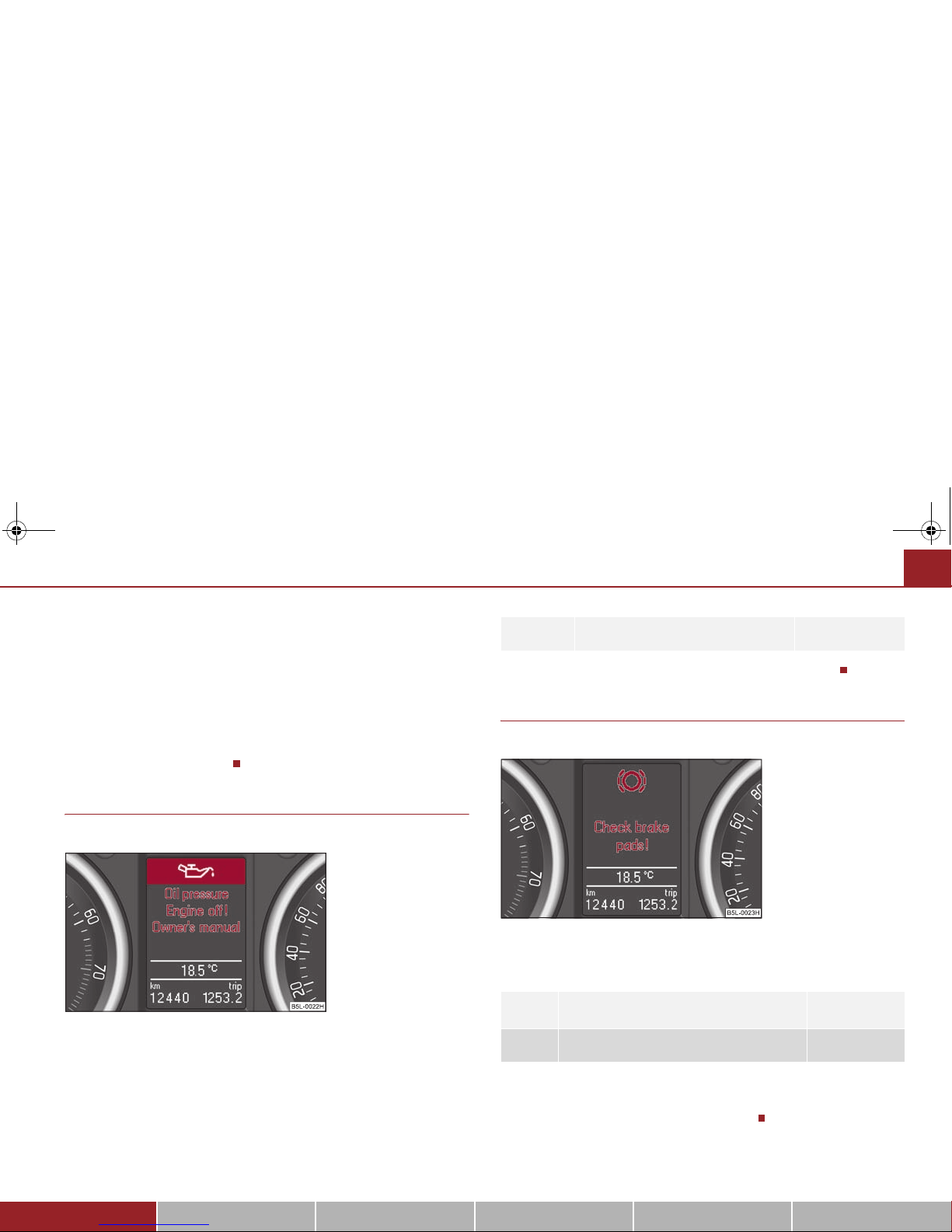
Brake pad worn ⇒ page 39
Fig. 33 Information display:
Brake pad worn
s2ak.b.book Page 29 Monday, April 6, 2009 2:13 PM
 Loading...