

Skipper ESN200 Operation And Installation Manual

ESN200
Operation and Installation Manual
Dual channel multi frequency Echo sounder
SKJIPPER Electronics AS www.skipper.no
Document no: DM-G005-SB
Rev: 1936
For software rev: 1.0.x
Date: 2019-11-11

SKIPPER Electronics AS
ESN200 Operation and Installation Manual
IMPORTANT
When doing service or repair, please wait two minutes after power o, before unplugging
internal connectors.
Do not run the sounder for a long time with the transducer in air.
The transducer may be damaged.
Weitergabe sowie vervielfältigung dieser unterlage, verwertung
und mitteilung ihres inhaltes nicht gestattet, soweit nicht
ausdrücklich zugestanden. Zuwiderhandlungen verpichten zu
schadenersatz.
Toute communication ou reproduction de ce document,
toute exploitation ou communication de ou son contenu sont
interdites, sauf autorisation expresse. Tout manquement à
cette règle est illicite et expose son auteur au versement de
dommeges et intèrèts.
Page 2 of 48
Copying of this document, and giving it to others and the use
or communication of contents thereof, are forbidden without
express authority. Oenders are liable to the payment of
damages.
Sin nuestra expresa autorización, queda terminantemente
prohibida la reproducción total o parcial de este documento,
asì como su uso Indebido y/o su exhibición o comunicación
a terceros. De los infractores Se exigirá el correspondiente
resarcimiento de daños y perjuicios.
Edition: 2019-11-11

ESN200 Operation and Installation Manual
SKIPPER Electronics AS
Contents
Table of abbreviations ........................................................................................................................................ 4
INTRODUCTION ............................................................................................................................6
SPECIFICATION ............................................................................................................................8
INSTALLATION ..............................................................................................................................9
Mechanical installation .................................................................................................................................... 10
Installation Details ......................................................................................................................................................11
SOFTWARE SETUP ......................................................................................................................13
Transducer ......................................................................................................................................13
Other echosounder parameters (Main setup) ..............................................................................................................15
Communications .........................................................................................................................................................16
Accepted NMEA inputs ..............................................................................................................................................17
Auxiliary set ................................................................................................................................................................18
Display adjustment ........................................................................................................................................... 20
Display setup .................................................................................................................................................... 21
Dimming setup ............................................................................................................................................................21
Alert setup and usage .................................................................................................................................................22
Connection between JB70E2 and Display units .............................................................................................. 26
Service software ..........................................................................................................................................................26
Display Unit setup – Network settings.......................................................................................................................26
JB70 setup ..................................................................................................................................................................27
Upgrading software .......................................................................................................................................... 28
Other transducers ............................................................................................................................................. 30
Options ............................................................................................................................................................. 32
Printing ............................................................................................................................................................. 33
Printers ........................................................................................................................................................................33
Saving to disk ..............................................................................................................................................................33
Continuous saving, .....................................................................................................................................................33
USER INFORMATION ................................................................................................................34
Introduction ...................................................................................................................................................... 34
Presentation ...................................................................................................................................................... 34
Selectable Information ................................................................................................................................................35
Manual mode .............................................................................................................................................................36
Screen Conguration ....................................................................................................................................... 37
Changing the look of the screen ....................................................................................................................... 42
Dimming and remote dimming ........................................................................................................................ 43
Saved depth / History ....................................................................................................................................... 45
Diagnostics ....................................................................................................................................................... 46
Lost bottom or input information ..................................................................................................................... 47
Diagnostics of the ESN200 using an ETT985 ................................................................................................. 48
Edition: 2019-11-11
Page 3 of 48
SKIPPER Electronics AS
ESN200 Operation and Installation Manual
Table of abbreviations
Symbol/abbreviation Explaination
TVG Time variable gain
FWD Forward position
AFT Aft position
PORT Portside
STBD Starboardside
Pic Speed Picture speed. The amount of time presented on the screen
DBT Depth below transducer
DBS Depth below surface
DBK Depth below keel
Draft Depth from water surface to the lowest point of the vessel
Oset Distance from Transducer to the lowest point of the vessel
DPTH Depth
M Meters
ft Feet
fm Fathoms
m/s Speed in meters / second
kHz kilohertz (Frequency)
hr hour
min minute
(A) Automatic mode (system self adjusts range and gain)
(P) Primary Channel
ALF Alarm method according to IEC61924/62288 / MSC 302 with cat-
egory (CAT)
A - Alarm to be acknowledged on the display only
B – Alarm may be acknowledged remotely
To work with ACN – Alarm Acknowledge, request, transfer, silence
ALR Older alarm standard to work with ACK Acknowledge
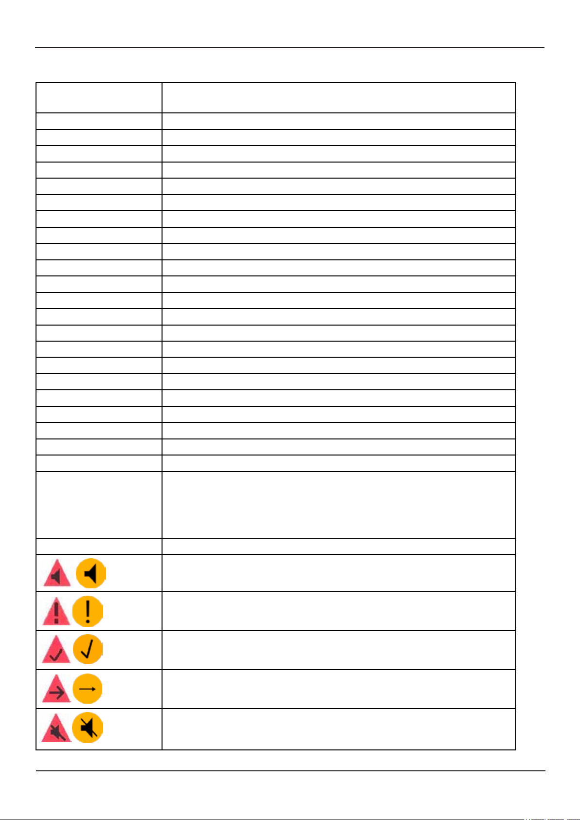
Active Alarm/Warning unacknowledged alarm
Page 4 of 48
Active Alarm/Warning acknowledged Alarm
Alarm/Warning rectied but unacknowledged
Alarm/Warning responsibility transferred
Alarm/Warning silenced for 30 seconds
Edition: 2019-11-11

ESN200 Operation and Installation Manual
Simulate mode
Mute Mode (see options section)
V Volts
DC Direct Current (for voltage)
CAM Central alarm management
INS Integrated navigation system
LAN Local area network
SFI System function identier, from standard IEC61192-450
UDP Data sent on the LAN ports
MAC Unique system identier for LAN system
IP Internet protocol address, unique in the network
SKIPPER Electronics AS
Edition: 2019-11-11
Page 5 of 48

SKIPPER Electronics AS
Chapter: Introduction
ESN200 Operation and Installation Manual
Introduction
The SKIPPER ESN200 is an echosounder from SKIPPER Multi series. It is made to fulll all ISO/
IMO standards, as well as the modern IEC standards for maritime equipment and alarm handling.
But it also fulls many extra function demanded on the modern ship.
Features
The ESN200 is a navigational echo sounder system that is made to full the needs of a modern
SOLAS vessel. Its aim is to be automated, so that the user does not need to adjust settings. But it
also allows the user to adjust if they feel the need.
The ESN is part of the SKIPPER Multi family, allowing the use of LAN to interconnect systems
and use multiple screens.
Features include:
• Easy and logical operation via a touch display, with fully automatic settings
• Flexible installation with minimal wiring
• Basic but comprehensive communication and features
• Fully integratable and frequently updated with the latest integration standards
• Possibility of multiple control units
• Remotely accessible
• Internal diagnostics and Built in test
• Up to 8 of the most used frequencies
• Approved for use with transducers as low as 38kHz giving a large variety of depths
• 2 simultaneous channels, each of which is frequency controllable
Page 6 of 48
Edition: 2019-11-11
ESN200 Operation and Installation Manual
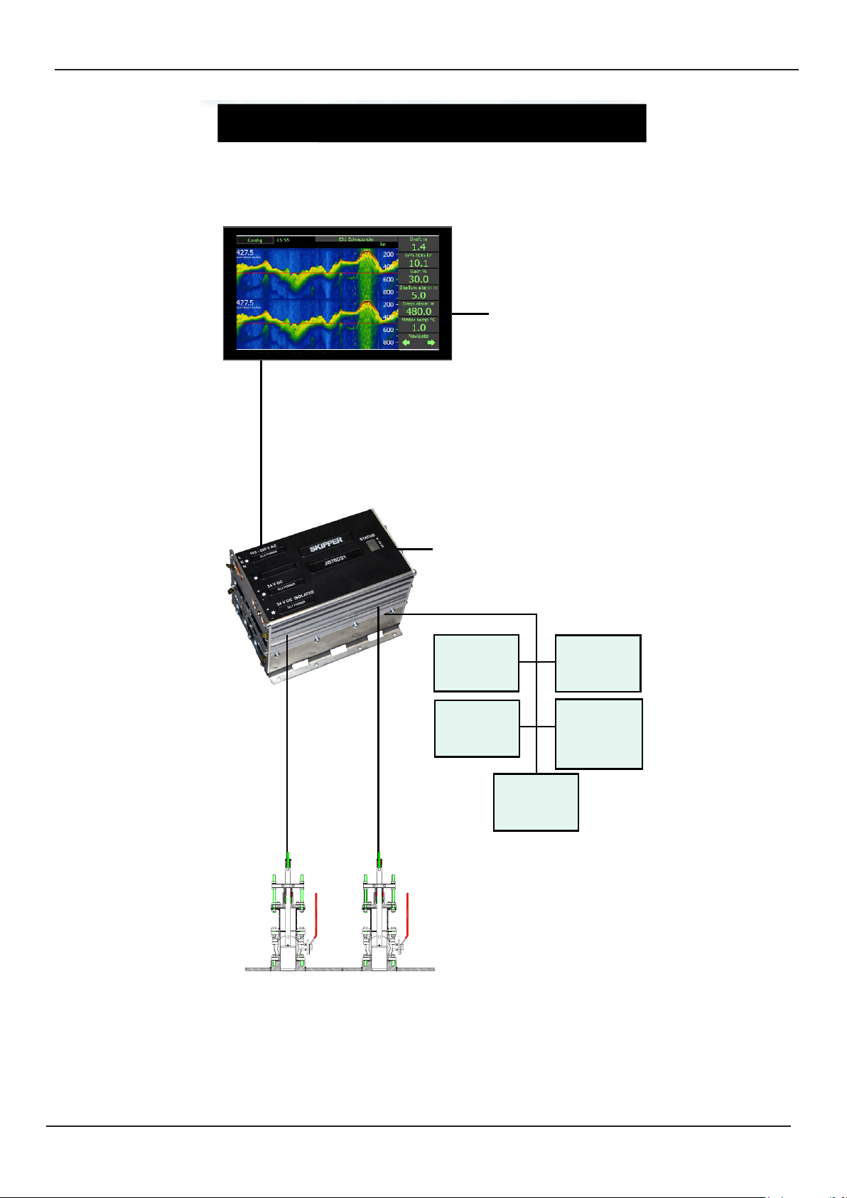
Overview
ESN200
Navigation Echo Sounder
Chapter: Introduction
Display unit ESN200-SB
LAN communication with Display
(Multiple displays available)
SKIPPER Electronics AS
24 V DC
Electronic / Transceiver unit
JB70E2-SA
24 V DC - 115/230VAC
Repeaters
Alarm
Radar
VDR
Conning
Display (also
dimming)
Edition: 2019-11-11
Options for tank,
sea valve (single and double hull)
and retrot.
Page 7 of 48
SKIPPER Electronics AS
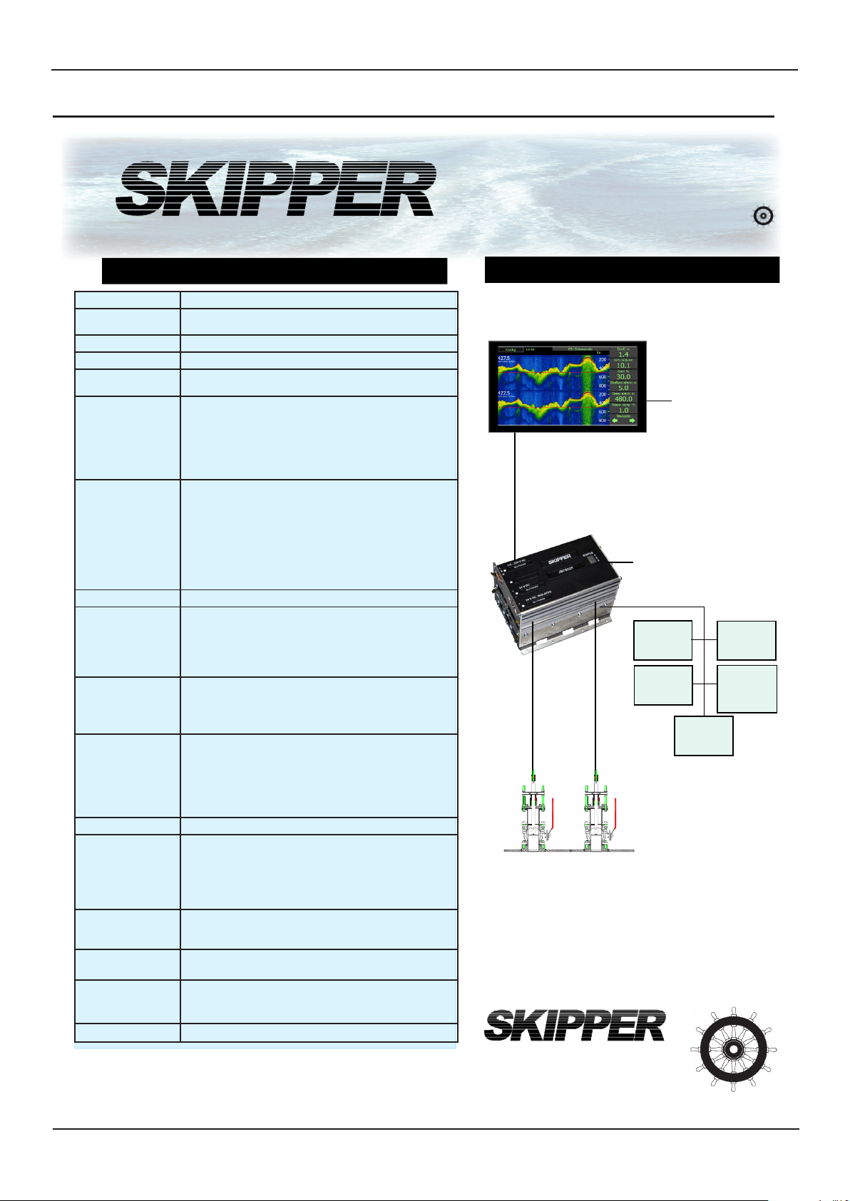
Specication
Chapter: Specication
ESN200 Operation and Installation Manual
ESN200
Navigation Echo Sounder
Specications
Channels Dual channel echo sounder
Transducer
connectors:
Frequencies 8 set frequencies 24,30, 33, 38, 50, 100, 200, 210 kHz
Power Supply DC: 20 - 32 V and/or 115/230VAC
Power
Consumption
Display
ESN200-SB
Electronic unit
JB70E2-SA
Ranges Selectable from 0 - 5 m to 0 - 5000 m
Approved SKIPPER
transducers with
expected depth
limits
Non-approved
SKIPPER
transducers
expected limit
Measuring Accuracy 1-10m: Accuracy 0.1m
Output power Nominal 700W. Max >1000W
User
functions
Print/Archive function
Depth alarms BAM compatible (IEC62923) ALF or ALR. Internal sounder.
Options IR31Dim Remote/Automatic dimming unit
Classication MED B approved
2 Transducer connectors in Electronic / transceiver unit.
Display unit. Nominal 6W
Electronic unit 20W
9” Resistive touch. 400NITS
Dimensions: 249 x 155mm
Weight:1.1kg
1 x LAN
2 x NMEA 0183 Outputs (IEC61192-1)
3 x NMEA 0183 Inputs (IEC61192-1)
Dimension: 115x115x180mm
Weight:1.5kg
2 x LAN (IEC61192-450)
5 x NMEA 0183 Outputs (IEC61192-1)
3 x NMEA 0183 Inputs (IEC61192-1)
1 x AUX in
2 x AUX out
1 x Relay out
50/200kHz ETS50200T/G 1m-750m
200kHz ETN200T: 1m - 350m
200kHz ETN200ST/G: 1m - 250m
50kHz ETN050T/G: 1m - 750m
38kHz ETN038T/G: 2 m- 1200m
24kHz ETN024T/G: 2m - 2100m
Resolution=0.1m
10m-100m Accuracy 1%
Resolution 0.1m
100m-5000m: Accuracy 1%.
Resolution Display=1m NMEA=0.1m
Auto mode (for all settings)
Manual control: Gain, Power, TVG, Frequency
Transducer setup by part number
Diagnostic screens / BIT
Dimming (remote or local)
Printers: By use of EPSON 350, OKI 280Elite, Network printers / Review: Service software via LAN
Extended Internal Logging, by USB or SD
Relay output and AUX in/out
CD401MR-SB Multi-repeater
ESN200-SB Extra Displays
Page 8 of 48
Overview
Display unit ESN200-SB
LAN communication with Display
(Multiple displays available)
Electronic / Transceiver unit
JB70E2-SA
24 V DC - 115/230VAC
Repeaters
Alarm
Options for tank,
sea valve (single and double hull)
and retrot.
SKIPPER Electronics AS
Norway
E-mail: sales@skipper.no
www.skipper.no
Version: 2019-11-11
24 V DC
VDR
Conning
Display (also
dimming)
Radar
Edition: 2019-11-11

ESN200 Operation and Installation Manual
Chapter: Installation
SKIPPER Electronics AS
Installation
The ESN200 comprises of 2 units and up to 2 transducers
ESN200-SB Display unit: Contains a 2 NMEA outputs and 2 NMEA inputs used solely for dim-
ming, or normal DPT outputs. An RJ45 connector is used for LAN communication (IEC61162-450)
to the Electronic/transceiver unit. Power input 24VDC
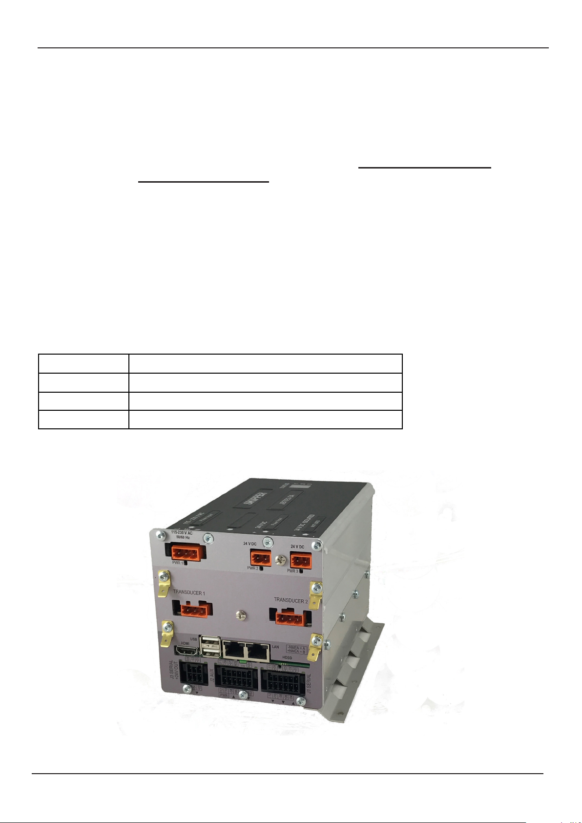
JB70E2-SA Electronic and transceiver unit; This unit is the echosounder producing the acoustic
signals and processing the returns to give the appropriate outputs for depth. It contains connections for 2 transducers, 2 LAN ports for connection to the bridge or control units, auxiliary inputs
and outputs, 5 NMEA outputs and 3 inputs, and power input 24VDC and 110-230VAC. This unit is
mounted on or close to the bridge, with long cables coming from the transducers.
If 7 outputs is not enough, the NMEA will typically be sent to a splitter/Expander such as the
SKIPPER NE108-SA to give the information to the bridge/alarm system and VDR.
Edition: 2019-11-11
Page 9 of 48
SKIPPER Electronics AS
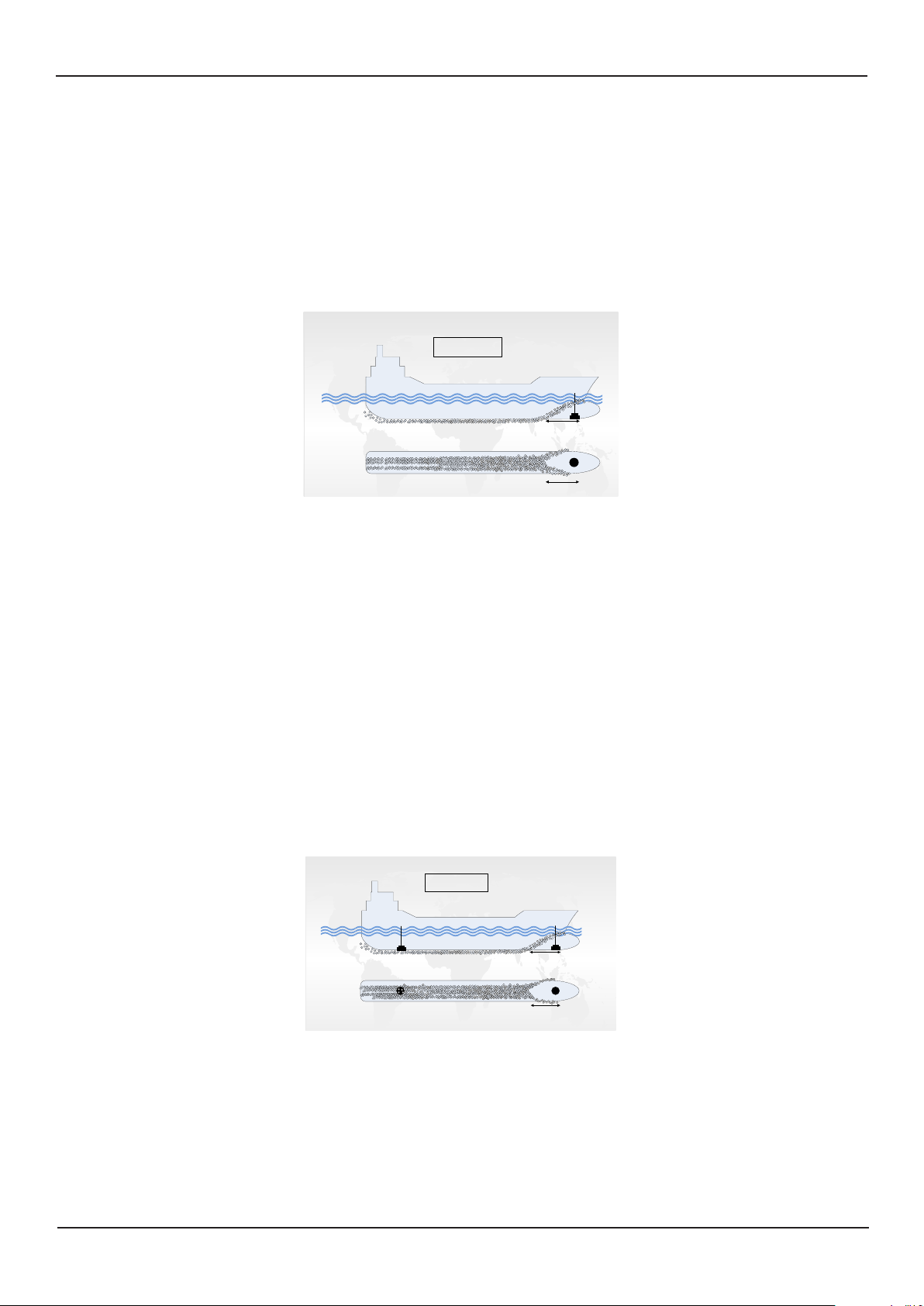
A
Bubbles
Single transducer
installation
A
Bubbles
Side view
Bottom view
A
Bubbles
Dual transducer
installation
A
Bubbles
Side view
Bottom view
Fore/primary transducer
(normally 50 kHz)
Aft/secondary transducer
(normally 200 kHz)
Often troubled with aeration
in speeds > 4-5 knots
Chapter: Specication
ESN200 Operation and Installation Manual
Mechanical installation
Positioning of the transducers
• A transducer should be installed in an area securing optimal measurement free from noise
and aeration.
• Transducers are normally installed in the noise free area in the foreship (see A on g.)
Optimal system operation is achieved by tting the transducer as deep as possible on the hull.
The transmitting surface of the transducer must be installed horizontally.
Do not mount transducers close to the propeller or aft of other hull installations (outlets, vents or
other protruding details). It is necessary to select a part of the hull that is submerged under all
load and speed conditions, and to avoid positions where air is trapped in heavy weather.
If a at, horizontal section is not available for transducer tting, the shipyard must construct a suitable bed.
Larger vessels are often tted with two transducers, one fore and one aft (see g.)
The fore transducer is the primary transducer, (normally 50 kHz).
The aft transducer is a secondary transducer, (normally 200 kHz).
An aft transducer may be troubled with aeration and turbulence and may not operate in higherspeed. It is normally solely used to measure aft depth in shallow water / slow speed.
Page 10 of 48
Edition: 2019-11-11
ESN200 Operation and Installation Manual
Chapter: Specication
SKIPPER Electronics AS
Installation Details
Refer to SKIPPER’s installation procedures in the appendix and on our web site www.skipper.no
regarding information about sea valve, tank installation, welding, cable glands etc
Note:
Protect the active element of the transducer and do not paint the surface.
Transmission in the air must be avoided! This may cause mechanical damage of the element.
Transducers should be positioned as close to the bow as possible within the rst 3rd of the ship. It
should be possible to draw a cone of +-60 degrees underneath the transducer without any objects
entering the cone. The face of the transducer should be horizontal with no more than 5 degrees
tilt. If this is not possible a blister should be assembled. This should have at least 0.3m of at area
in front of the transducer, and be tear drop shaped.
Generally there should be nothing in front of the transducer that can cause turbulence within 2m.
and 0.5m to the side.
Positioning/wiring of the units
Length Transducer cable type: Twisted shielded pair
25/40m Connected transducer cable
40-100m 1.5mm
100 – 300m 2.5mm
Edition: 2019-11-11
Page 11 of 48
SKIPPER Electronics AS
Transducer 1
Chapter: Specication
ESN200 Operation and Installation Manual
E
ADD RESISTOR
TO GIVE MAX 100 mA
24 V = 220 Ohm
5 V = 50 Ohm
POWER
+-+-+
DC
AC
NMEA 2 OUT
NMEA 2 OUT
120801 0411
1
(Not in use)
L
0 V
0 V
+24 V
+24 V
N
G
00
Revision
CD-2043
N/A
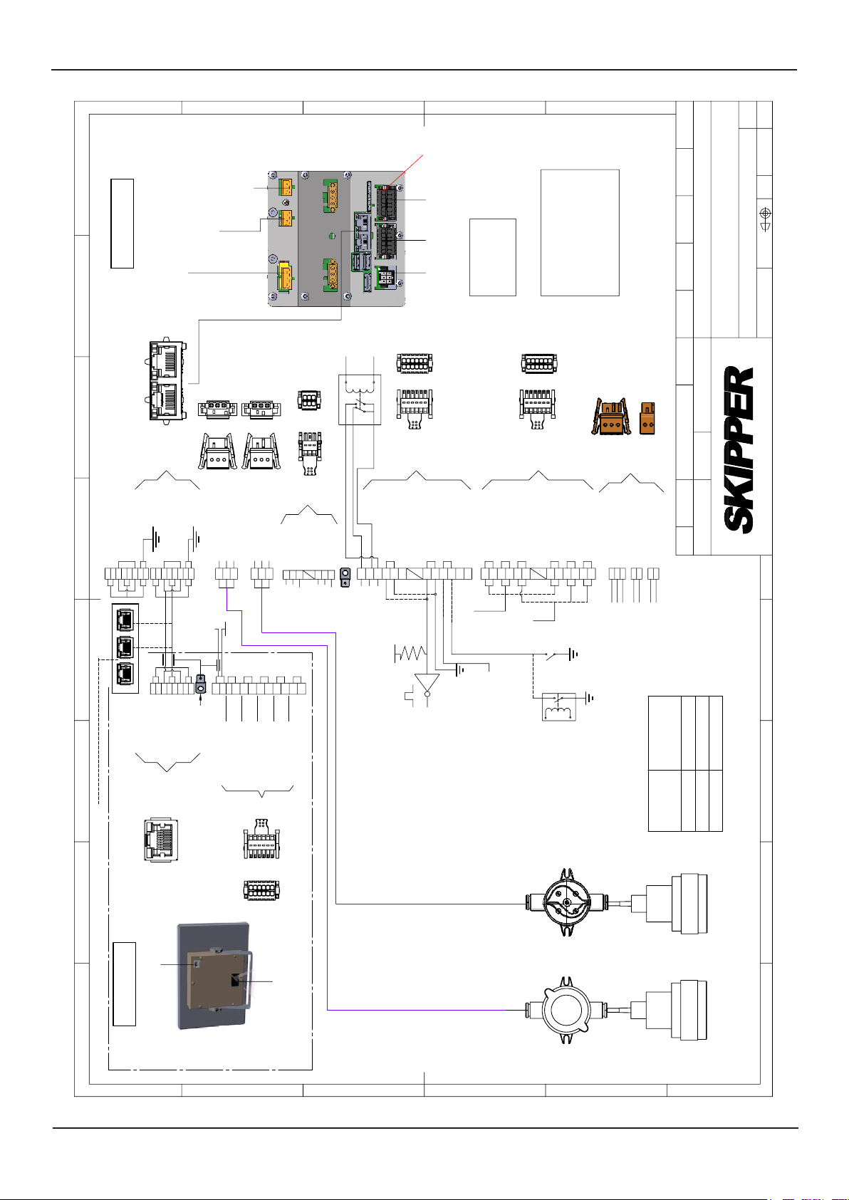
Wiring diagram for ESN200
Material
Approved by - date
diverse Connectorer
Endret til ESN200-SB og lagt til/endret
2018.1.15 ST
Checked by
JB70E2-SA
Endret til
2018.08.28 ST
CN
Designed by - date
Drwg. no.
Name
PC 2018.11.15
ST 2018.06.12
1 of 1
Sheet
2018.11.15
Edition date
Scale
Eur. projection
ISO2768m
Gen. tolerance
Electronics AS
ALARM
NO
C
PIN 1
J3 J2 J1
2
12
1
11
COM.
NC
A
8
JB70E2-SA
7
6
ESN200
AC (115V-230V)
Power for DL2
ESN200
DC (24V)
Power for DL2
B
NOT USED
Coded plugs
Transducer 2Transducer 1
Coded plugs
2
6
1
5
LAN
J3
GND
R1
-
AUX OUT 2
R2
+
-
Transducer 1
White
Gnd
Black
Transducer 2
Black
Gnd
White
321
+24 V
NMEA 3 IN+
NMEA 3 IN -
R2
0301 05
R1
0 V
NMEA 3 OUT+
NMEA 3 OUT -
0402 06
AUX OUT 1
01
5
321
82 71 5 63 4
7 84 5631 2 212132
1 2 3
+-+
AUX IN 1
AUX 5 V
1210080604021109070503
D
NMEA + = B
+
+
-
NMEA 1 IN
AUX 0 V
0703 10060205 09
NMEA - = A
2
12
1
11
J1J2
-
+
-
NMEA 1 OUT
NMEA 1 OUT
R2
R1
AUX OUTPUT
*
-
NMEA 2 IN
SWITCH
4
3
TO INS. IEC61162-45O
2
1
CAT 5e
OR BETTER
75
84 6371
2
LAN
LAN
ESN200-SB
24 V
4
+
B+
GRD STUD
Power input (24VDC)
0 V
61 2 3
5 98
A -B+A -
CU NMEA 2 IN
CU NMEA 3 OUT
CU NMEA 3 IN
CN 1
11
12
10
11
12
B+
A -B+A -
CU NMEA 1 IN
CU NMEA 1 OUT
1
2
CN 1
5 -24V
*
PULSE
LEVEL
OUTPUT
GPS / BAM
5 -24V
ALARM +
BAM / VDR
INS/ECDIS
RADAR
RESET -
ALARM
Do not ground
screen here
L
N
G
0 V
+24 V
4
1,5mm²
2,5mm²
Cable Area
3
>300
0-100
cable
Length of
100-300
2
Transducer 2
1
Page 12 of 48
A
B
C
D
E
F
Edition: 2019-11-11
ESN200 Operation and Installation Manual
Chapter: Software setup
SKIPPER Electronics AS
Software setup
Transducer
Once connected the system requires the installer to identify which transducer is connected to
which of the 2 connectors. System required 1 approved transducer to be installed (currently
200/50/38 kHz), the second can be any transducers.
The approved transducer should be set to primary, and this is the transducer that reports the
standard DPT output messages.
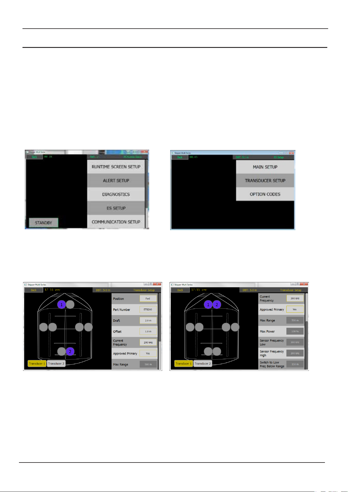
Both connectors can have a transducer tted. To select the correct xture, start the system and go
to the cong menus, and then the ES setup.
Here you can select the transducer menu and by clicking on the transducer connector port you
can move the transducer to the appropriate area of the vessel, and select the transducer, by part
number. This will change the parameters to match your transducer.
Edition: 2019-11-11
Page 13 of 48

SKIPPER Electronics AS
Chapter: Software setup
ESN200 Operation and Installation Manual
If you are not using a standard transducer, then select other, and the frequency, max power and
max expected range can be set for that
Selectable transducer types
Part number Type Approved
for use
ETN050 50 kHz of types ETN50(X)G, ETN50(X)T Yes
ETN200 200kHz of types ETN200(X)T Yes
ETN200S 200kHz of type ETN200S(X)G, ETN200S(X)G Yes
ETN50200 Combined 50 and 200kHz of types ETN50200(X)G and N50200(X)T Yes
ETN038 38 khz Yes
8B-200 Furuno 200kHz Transducer Yes**
Other Any other No
ETN024 24kHz No
** Transducers not manufactured by Skipper should be tested using the ETT985 Tester to prove the transducer is within specication (The named transducers have BV reviewed tests, proving they work to speci-
cation with the system).
Standard transducers have the required values set. These can be changed in the settings of
‘Other’ See section ‘Other Transducers’ At least 1 installed transducer should be within the SKIPPER approved list.
Page 14 of 48
Edition: 2019-11-11
ESN200 Operation and Installation Manual
Chapter: Software setup
SKIPPER Electronics AS
Other echosounder parameters (Main setup)
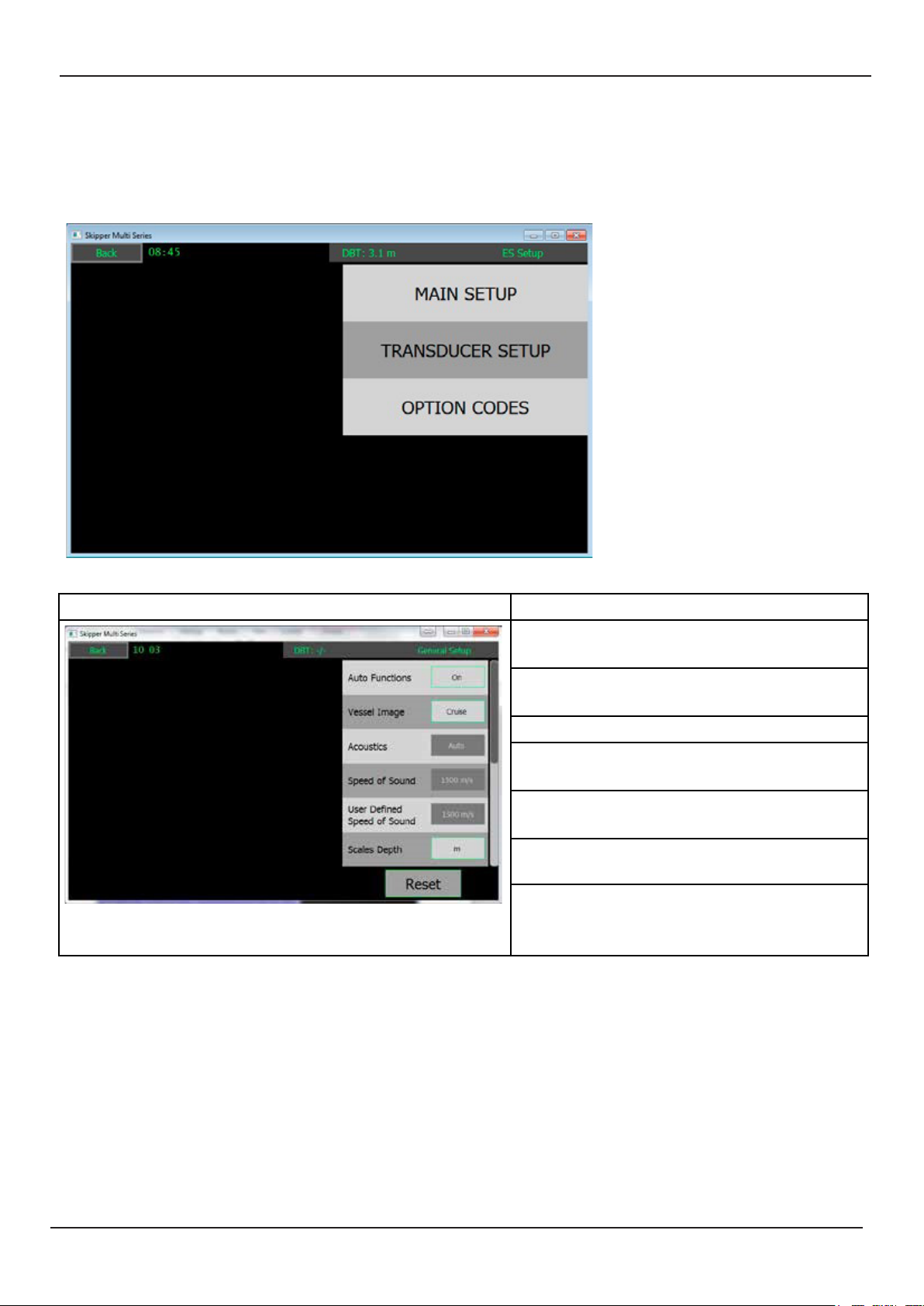
Other echosounder parameters are set by default, but can be adjusted in the ES menu if required.
Some parameters and functions must be activated using a code number in the option codes tab.
This is to prevent users inadvertently changing parameters that can make the system perform
poorly.
Screen Main setup
For options, see the options appendix
Auto functions will take control of range
gain (and frequency)
Change the design of the vessel in the
menus
Acoustics, ping method (not in use)
Speed of sound can be changed with an
option or with a temperature input
User can dene the sound speed with an
option
The depth scale (also available on
screen)
Reset will reset the settings to default
Edition: 2019-11-11
Page 15 of 48
 Loading...