

Document XXX
Revision 1824
Date 2018-06-12
Software version 01.01.32
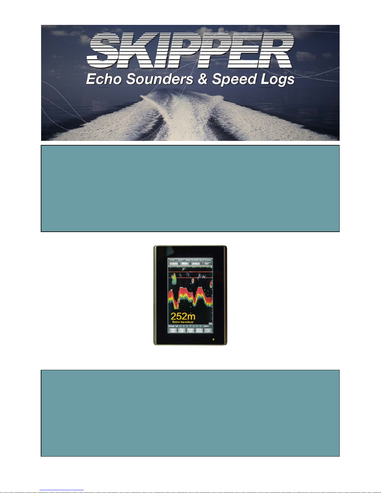
EMES60
Navigational Echo sounder
User manual

1
EMES60 is a combined echo sounder and speed log, providing both
speed and water depth from the same unit.
This manual gives the information necessary to use the Echo sounder
system.
Table of Contents
Table of Contents
Introduction

2
Introduction ................................................................................................................................ 1
Table of Contents ....................................................................................................................... 2
1 About this Manual .............................................................................................................. 4
1.1 Glossary .......................................................................................................................... 4
1.2 Parts of the Manual ...................................................................................................... 5
2 Introduction to EMES60 ....................................................................................................... 6
2.1 Summary ......................................................................................................................... 6
2.2 Highlights ........................................................................................................................ 6
2.3 System Structure ............................................................................................................ 7
3 Operation, generic ............................................................................................................. 8
3.1 HMI Touch-Screen C ontrols......................................................................................... 8
3.2 Structure of the operational screen .......................................................................... 8
3.3 GNSS and THD sensors data ....................................................................................... 9
3.4 Using the on-screen keyboard to enter data ......................................................... 9
3.5 Miscellaneous buttons ............................................................................................... 10
3.6 Administrator mode ................................................................................................... 10
3.7 Home screen ............................................................................................................... 10
3.8 Alerts .............................................................................................................................. 13
3.9 Screens navigation ..................................................................................................... 14
3.10 Brightness control ........................................................................................................ 15
3.11 Hardware interface setup ......................................................................................... 15
3.12 Demo and Simulation modes................................................................................... 17
3.13 Printing and screen snapshots ................................................................................. 18
3.14 Setting the time and date ........................................................................................ 19
4 Operation, Echo sounder ................................................................................................. 20
4.1 Echo sounder Home screen (screen 0) .................................................. 20
4.2 Echosounder main operational screen (screen 1) ............................... 21
4.3 Echosounder digital indicator screen (screen 2) ................................... 24
4.4 Echosounder alert configuration screen (screen 3) ............................ 25
4.5 Echosounder communication screen (screen 4) ................................... 28
4.6 Echosounder Interface Unit setup screen (screen 5) ............................ 31
Table of Contents

3
4.7 Echosounder history screen (screen 6) ..................................................... 35
4.8 Echosounder oscilloscope screen (screen 7) .......................................... 36
4.9 Echosounder test and troubleshooting screen (screen 8) .................... 37
5 Specifications .................................................................................................................... 38

4
1 About this Manual
1.1 Glossary
Terms used in this manual include:
DIV Division
echo sounder
A device that measures the depth of water under a ship, by
measuring the time between sending a sound pulse and
receiving its echo from the seabed
electromagnetic log
A type of speed log that uses electromagnetic
measurements to calculate the speed of a vessel through
water. Compare with acoustic Doppler log, which calculates
the speed through the water or relative to the seabed by
detecting shifts in frequency of acoustic echoes. EMES60 uses
an electromagnetic log.
HMI Human-machine interface: screen units that give readouts of
speed and depth, and allow the user to control and set up
the system
IMO International Maritime Organization
Interface Unit
EMES60 electronic unit that connects sensor, Sensor Power
Unit and ship’s power
longitudinal speed Speed in the aft-fore direction of the vessel
opto Short for “opto-isolated”
opto-isolated An electrical input that is separated electrically from the
inputting device using an optical converter circuit
Sensor Power Unit EMES60 electronic unit that connects HMI units, external
equipment and Interface Unit
speed log
A device that measures the speed of a ship relative to the
water around it and the seabed under it
TVG
Time Varied Gain, signal compensation that removes
transmission loss effects from echosounder data
transducer A device that converts electrical signals to sound and back
again
transverse speed Speed in the port-starboard direction of the vessel

5
swipe technique Touch and drag – common scrolling technique applicable to
the touch screens.
1.2 Parts of the Manual
• Section 1, About this Manual, introduces this manual.
• Section 2, Introduction to EMES60, provides an overview of the system.
• Section 3 and 4, Operation, describes the day-to-day operation of the
system, including how to use the information and control screens.
• Section 5 provides EMES60 System Specifications.

6
2 Introduction to EMES60
2.1 Summary
EMES60 is a combined electromagnetic speed log and echosounder navigation
system. It is a single sensor with two transducers in one housing.
Both parts have been designed to meet the relevant international standards and
provide all the modern and legacy input-output interfaces that are s pecified by
the IMO standards.
As required by the relevant regulations, the two parts are totally separated
internally.
The main advantage of this arrangement is that the system only needs one hull
penetration, and one set of mounting hardware, thus increasing reliability and
reducing costs of installation and maintenance.
The size and weight of the sensor is significantly less than other systems on the
market, which greatly facilitates installation and handling.
2.2 Highlights
• Only one hull penetration, which increases safety of navigation
• Small overall diameter of sensor, requiring small hull penetration, which
minimizes the risk of mechanical damage
• Sophisticated analog and digital signal processing, which provides reliable
data in any navigation conditions
• All modern and legacy input-output interfaces are supported, including
IEC61162-1
• Sound speed calibration based on temperature, which provides accurate
depth measurements in different conditions without the need for manual
adjustments
• Includes water temperature sensor, accurate to 1°C
• Optimized electromagnetic log operational parameters, which provides
accurate speed through water measurements in different water conditions,
such as sea water, river water, and brackish water
7
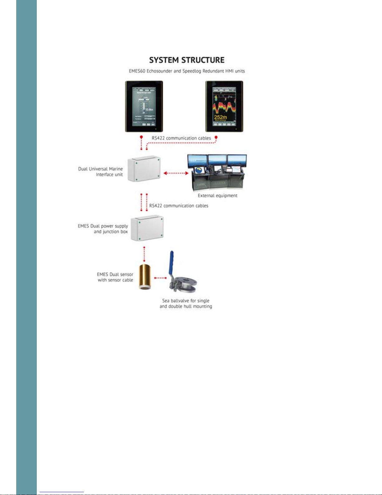
2.3 System Structure
8
3 Operation, generic
3.1 HMI Touch-Screen Controls
Reading the speed and depth information from the system, and configuring the
system for use, is done through the touch-screen display units, called “humanmachine interface” (HMI) units.
Data is also sent to external equipment using a range of standard communication
protocols an d data formats.
Two HMI Units are usually fitted, both of which can run both the echosounder and
speed log parts of the system, but typically one is configured to run the
echosounder, and the other is configured to run the speed log.
The HMI Units use touch-screen technology, so that controlling the system is done
by touching the relevant part of the HMI Unit screen.
The structure and operation of both HMI units is similar. The examples below are
from the echosounder, but the principles are the same for the speed log.
3.2 Structure of the operational screen
GNSS and THD sensors data, ref 3.3
Miscellaneous buttons, ref 3.5
Main window: different for each system and
each screen type
Settings buttons: touch to change
settings and Home access, screen
Simulation mode indicator
9
The exact contents of the parts of the screen are different for each screen type;
see the section for each screen for detailed information.
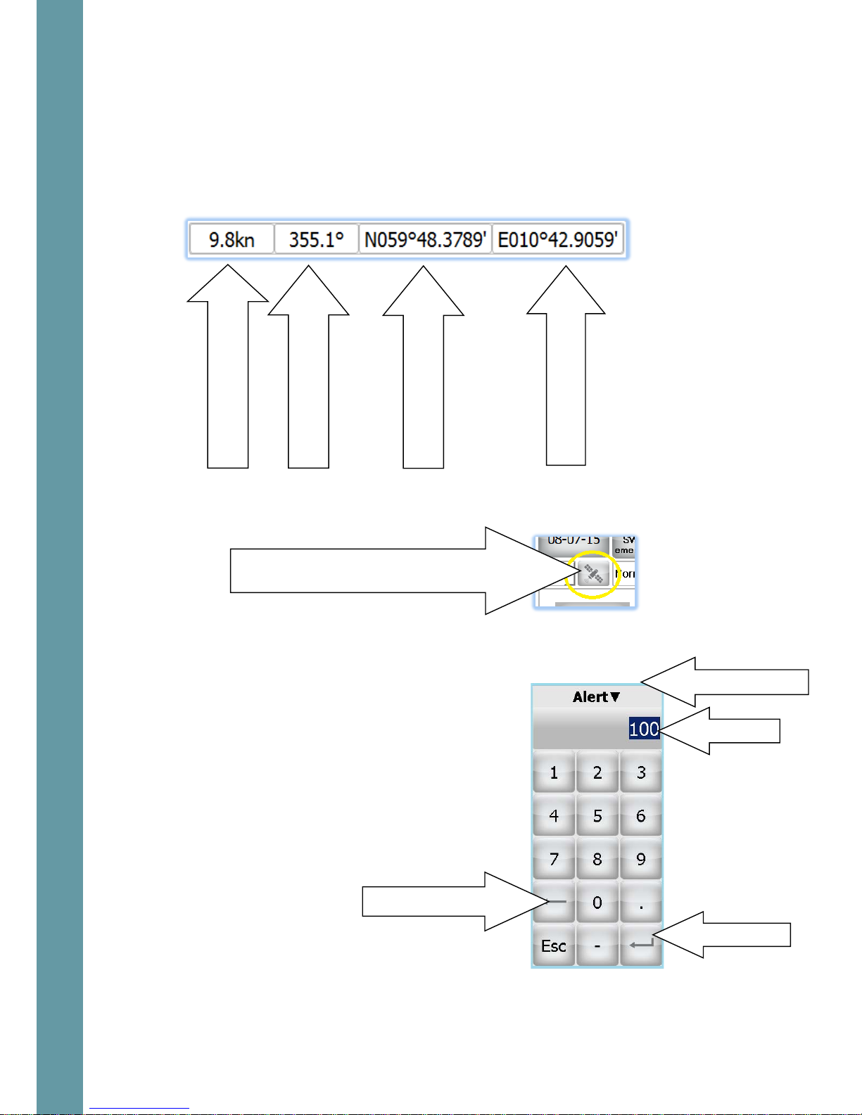
3.3 GNSS and THD sensors data
All the screens show GNSS and THD sensor data received by the system in the top
row of the screen.
This section can be enabled or disabled using the GPS Display on/off button at the
top of the Home screen.
3.4 Using the on-screen keyboard to enter data
On-screen keyboard is used to change some of
the user adjustable settings. The upper line
contains the name of the edited parameter. The
operator should enter the desired value and
press the “enter” button. Backsp ace butto n can
be used to delete the characters to the left from
the cursor. In order to cancel operation without
saving the changes – press the Esc button
or touch any area
Outside the keyboard frame.
GNSS receiver speed
Heading
Position, Northing
Position, Easting
Touch to toggle GNSS displaying
Backspace button
Parameter name
10
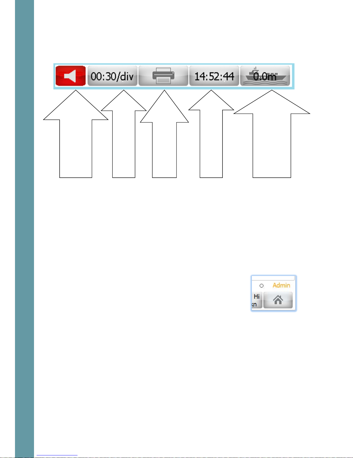
3.5 Miscellaneous buttons
The second row has a set of buttons, which provide numerical outputs as well as
controls for the system. Each screen type is slightly different, but a typical one is as
follows.
3.6 Administrator mode
EMES60 has two input modes: “Normal User” and “Administrator”.
Some operational parameters could prevent correct operation of EMES60 if they
are set incorrectly. These parameters cannot be set in Normal User mode, and the
operator must change to Administrator mode in order to get access to the setup
screens.
All setup, calibration and troubleshooting screens are accessible only in
Administrator mode.
The system starts in Normal User mode. To change to
Administrator mode, go to the Home Screen (ref 3.7), and
enter the Administrator password in the “Password” section.
The administrator password is 1963
The current input mode is shown at the bottom of the
screen.
3.7 Home screen
Touch the button in the bottom-right of most screens to access the Home screen.
Window-specific control;
echogram advance
Screen dump or
continuous printing
Time display:
touch to
change the ti m e
System specific control
Draft – for echosounder,
Water temperature for
speedlog
Alarm indicator:
touch to see the list
of active alarms
11
Home screen layout
The Home screens of the Echosounder and Speed Log interfaces are similar, but a
different selection of screens is available for each.
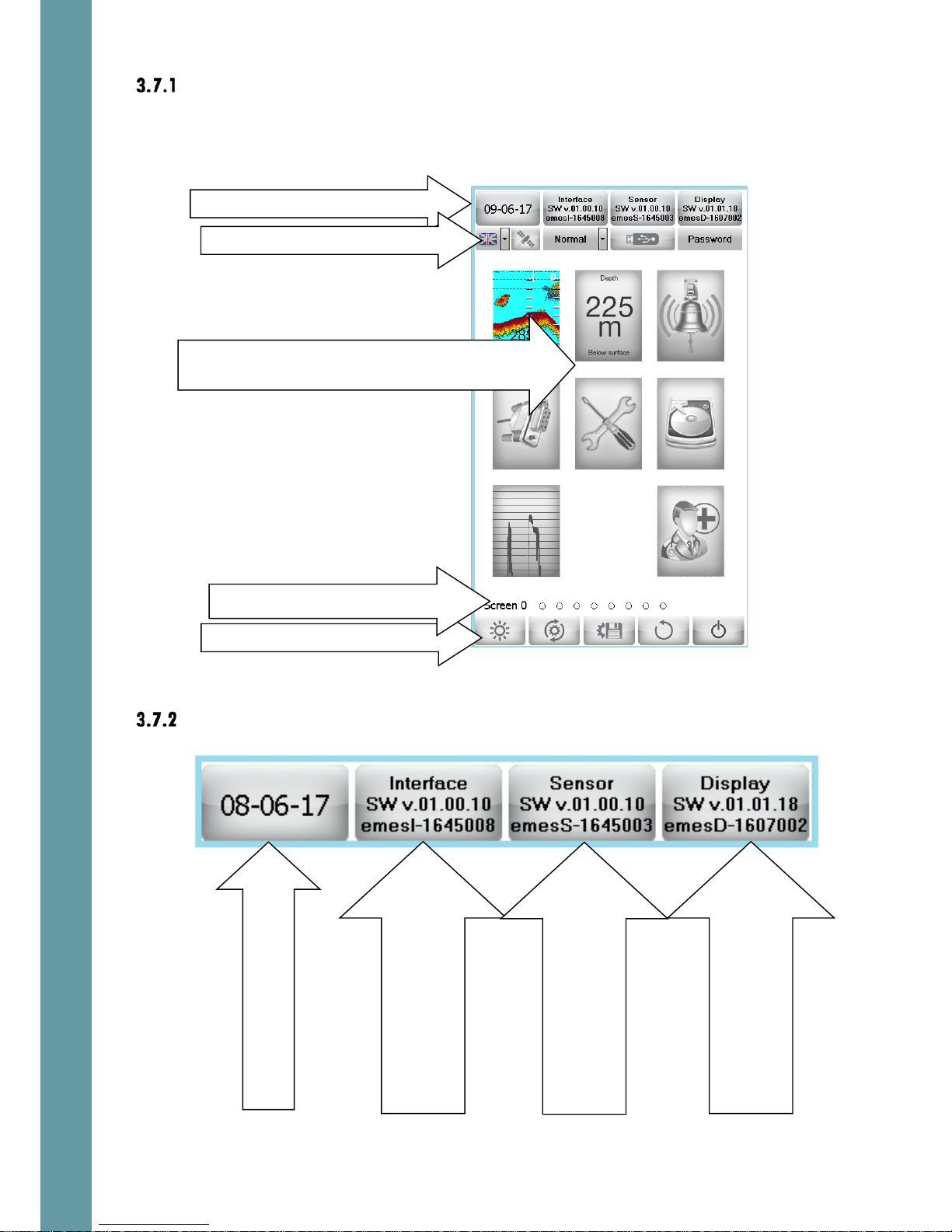
Home screen upper line
Screen selection: touch to select an operational
screen
Home screen Control buttons
Home screen Upper line
Home screen Second line
Screens navigation
SW version and serial
number of Interface Unit.
Touch to up grade software
Date:
touch to change
SW version and serial
number of Sensor Unit.
Touch to up grade software
SW version and serial
number of HMI(Display) Unit.
Touch to up grade software

12
Home screen second line
Home screen Control buttons
Day/Night mode: touch to toggle between Day
and Night display modes. The button shows the
current mode. In night mode, the display is shown
in darker colors, to preserve the night vision of the
user. A sun icon is shown in Day mode, and a
moon in Night mode.
Defaults: sets the system settings to default values.
You are then presented with the option of restoring
to either the ship’s defaults (see below) or factory
defaults.
An “Are You Sure” screen appears when the tick
button is touched. Touch “OK” to return all the
settings of the system to the selected set of settings.
Store ship’s default settings: stores the current
settings of EMES 60. This function is recommended
after the required setup is performed. Then it will be
easy to restore the original settings in case of
accidental in case of accidental loss of the
settings. Also see Saving Files to USB, section 7.1.
Return to Screen: returns the display to the previous
operational screen
Toggle ON/OFF GNSS and
heading indication line on
the operational screens
Language select
Toggle between
Normal/Demo/Simulation
modes
ref
3.12
Activate functions related
to USB disk, ref 7.1
Enter the password – to
change the privileges
(User, Admin, and Service).

13
Standby: turns the system in Standby mode. An
“Are You Sure” screen appears when this button is
touched. Touch “OK” to turn the system in Standby
mode.
3.8 Alerts
Alerts basics
If a value goes over a minimum or maximum limit, or functional failure occurs, an
alert will be triggered. This causes the following things to happen:
• A flashing text indicator is shown in a
prominent position on the screen
• The alert state is logged to an alert list, with the time stamp of the alert status
change
• The potential free relays in the Interface Unit can be activated (depending
on the settings of each relay function, ref section 6.6.4). These can be used
to trigger audible alerts or set alerts in other systems.
To acknowledge an alert, causing the on-screen warning to disappear, touch the
flashing warning box. More than one alert condition could be in place at the same
time, so it may be necessary to repeat this procedure to acknowledge the other
alerts.
The alert parameters are adjusted, controlled and monitored using the Alert
screens, ref sections 4.4 and 5.4
The “loudspeaker” button is on provided in the
second line of each screen. The color of the
button depends on the existing alarm
conditions. If any alarm condition exists – the
button is red, otherwise – grey.
Touch the “loudspeaker” button and the active
alarms list will appear.
Alarm status can be “Active” or “Inactive”
Acknowledge status can be “A”
(Acknowledged) or “N” (Not acknowledged)
This way it is always possible to check the alarms
status after they has been acknowledged.
Generic alert conditions
There are several alert types, which are common for both echosounder and speed
log systems.

14
These are:
Void
Void
void
The alert types which are specific to one of the systems are explained in 4.4 and
5.4
Setting alert limits
The values at which alert is triggered are shown in Alert Buttons at the bottom of
the screen. There are two buttons, one for the alert when the value gets too low,
and one for when it gets too high.
To change these values, touch one of the Alert
buttons.
A digital keyboard appears on the screen; Enter
the desired value in the edit line and press “Enter”
button.
The value in the Alert button changes to show the
new selection.
3.9 Screens navigation
Use the Screens Navigation part of the screen to
go directly to a different screen: touch the dot
for the required screen.
Alternatively, “swipe” to left or right to move to an adjacent screen. The current
screen is shown as a filled dot.
IMPORTANT NOTE: Entire set of screens is available only in admin mode, ref 3.6. In
the user mode there are only basic screens (which are needed for a daily use) can
be sel ected.

15
3.10 Brightness control
Double-tap in any screen area, and a brightness control slider is
shown. Slide it up and down to increase and decrease the
brightness of the HMI screen.
If the brigthness is set so low that the screen picture is not visible
under the present ambient light conditons – touch any part of the
screen and keep touched for ca. 3 seconds. The brigtness will
change to a value so thee elemensts of the screen as visible in all
light conditions.
3.11 Hardware interface setup
Screen layout
This screen is used to program the Interface Unit according to the specific
requirements of the installation.
This screen can be accessed from both speed log and echosounder modes.
The default settings can be restored when necessary
Touch here to change day/night mode

16
The following outputs are available:
Relay outputs
These are controlled from the Alerts screen (ref 4.4 and 5.4)
Ref 6.5.25 for connections details.
Opto outputs
Two opto output channels are provided.
Touch the box next to each opto channel to
assign the function to this channel. Select “Not
Used” if no action is needed on that channel.
The functionality is different for speed log and
echosounder systems. Ref 4.6.7 and 5.6.7 for
further details
Factory default: Not used.
Opto outputs: touch to select the functions that drive
the Opto output channels
Pulse inputs: touch to select what happens when a
pulse is received on a pulse input channel
Analog outputs: touch to select the signals that drive
the Analog output channels
Screen copy: touch to select where screen
copy (print screen) is sent. Touch the printer
name to select the alternative
COM outputs: check/uncheck the boxes to select the messages
that are provided on the serial data output channels. Touch the
baud rate value – to set desired value

17
Pulse inputs
A signal received from an external system can
be selected to cause an action in the EMES60
system.
Two pulse input channels are provided.
The functionality is different for speed log and
echosounder systems. Ref 4.6.5 and 5.6.4 for
further details
Ref 8.2.6 for input connection details.
Factory default: Not used
Analog outputs
Analog outputs can be configured to provide
a varying voltage output in response to a
measured value in the EMES60 system.
Two analog output channels are provided.
Touch the first box next to the channel number
to switch between 0 to 10 V voltage output and
4 to 20 mA cur rent output.
The functionality is different for speed log and
echosounder systems. Ref 4.6.8 and 5.6.8 for
further details
Factory default: Not used
Screen copy and printing
Controls what happens when the Print Screen
button at the top of most windows is touched
Touch Printer to send screen copy images to a
printer, and File to send them to a file, stored in
the HMI memory.
Touch this box to select the printer from a list of
available system printers.
3.12 Demo and Simulation modes
EMES60 can be put into special modes, to help with training and testing.
Function
select

18
Demo and simulation modes are set in the
Home screens; touch the mode button and
select the required mode.
Warning: ensure that the mode is set to Normal
when EMES60 is used for navigation.
The available modes are:
• Normal: the information shown in the screens and the outputs from the
external interfaces are driven by the measurements made by the speed log
and echo sounder sensors.
• Demo: the screens are driven by artificial speed log and echo sounder data,
which is computed inside the EMES60 software. This mode is supposed to be
used for presentations.
• Simul: simulation mode; in this mode, the screens and outputs are also driven
by data computed by the EMES60 software, but the operator can program
the parameters of the data that is shown and output.
This is useful for training and checking the connections to the external
equipment, when real data from the sensor head is not available.
To set the simulation parameters: select simulation mode, then go back to
screen 1. Click in the area of the digital depth (or digital speed) indicator –
to change the simulated data.
Note that when either demo or simulator mode is activated the large
character S is indicated in the upper right part of all screens.
3.13 Printing and screen snapshots
Touch the Print Screen button to send data from the screen to a
printer or to the file screen for debug and maintenance
purposes.
In Echosounder mode, keep this button touched for 3 seconds
ant this this will start a continuous printout of the echogram and
the GPS position data.
The function of this button is controlled by the selection of the
Screen copy alternatives in the Hardware Interface Selection
screen (ref 3.11.6).

19
3.14 Setting the time and date
Touch the time display box to open the time-setting menu. Click
on the hours, minutes or seconds, and use the up and down
arrows to change them. Then touch the “tick box” to set the new
time.
Go to screen Home and touch the date button. Use the date
control dialog to select the required date. Then touch the “tick
box” to set the new date.

20
4 Operation, Echo sounder
The echosounder function measures the depth of water under the vessel.
4.1 Echo sounder Home screen (screen 0)
This screen is used to go to the desired operational screens, and for general
controls.
See section 3.7 for detailed description of all screen elements.
See 3.7.4for use of the Control buttons.
Date: touch to change; SW Version
Language selection, GPS ON/OFF, Operation
mode, Password
Screen selection: touch to select a screen type
Screens navigation
Control buttons

21
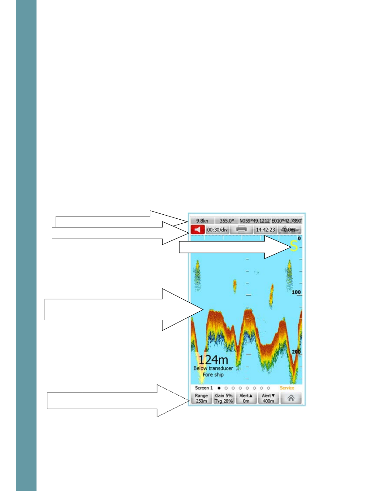
4.2 Echosounder main operational screen (screen 1)
Screen layout
This screen is the one that is shown in normal use of the echosounder.
It displays the echogram (a scrolling color-coded view of water column and seabed
echoes) and depth.
Speed, heading and GPS position information is indicated in the top line of the display.
Image scrolling speed (minutes: seconds per division), time and draft are indicated in
the second line.
The following parameters can be adjusted with this screen:
• All transceiver settings (GAIN, TVG)
• Shallow and Deep alert limits
• Range and picture speed
• Ship’s draft
• Units of measurement
Range and Transceiver settings: touch Gain /Tvg to
set transceiver parameters
Alert settings: touch Alert button to set alert limits;
Alert status: touch to see alerts list;
Scroll speed, touch to change;
Print screen/continuous print;
Time: touch to change;
Draft: touch to calibrate;
Echogram; Depth scale: touch and drag
upwards/downwards the to change scale
Depth readout with units; Origin of depth; Location of
transducer; Indic a tor size; Touch this area – to adjust these
parameters; ref 4.2.2
GNSS and THD data, ref 3.3

22
Changing digital indicator settings
Touch the Digital Indicator area to show a control menu,
which allows you to change the values that are shown.
Touch the corresponding box to show a list of available
selections.
Depth ref(erence) selections are:
• Below transducer: the depth shown is from the sensor to the seabed
• Below surface: the depth shown is from the water surface to the seabed
• Below keel: the depth shown is from the bottom of the ship’s keel to the
seabed.
Depth units control the units that the depths are shown in; selections are:
• m: meters
• ft: feet
• Fm: fathoms
Sensor pos(ition) control allows the position of the sensor to be shown. Selections
are:
• Fore ship: the sensor is at the front of the ship
• Aft ship: the sensor is at the back of the ship
Digit controls the size of the text that shows the depths; selections are:
• small: depth is shown in a small font
• large: depth is shown in a large font
Changing depth scale
Touch and drag the echogram area to change the scale of depth that is shown in the
display. Drag downwar ds – to reduce the range. Drag upwards – to increase the range.
Alternatively – touch the Range button and enter the digital value from the screen
keyboard.
Changing picture advance speed
The right-to-left scroll speed can be changed by either of the following:
• Touch the scroll speed indicator to open an adjustment slider
• Touch and drag over the time scale area in the top of the echogram area
Setting the draft offset
The button with a picture of a ship adjusts the vessel draft offset.
Touch this button, and on-screen keyboard appears. Enter the
desired value and press Enter button.

23
A positive value is the distance between the transducer and the water surface. A
negative value is the distance between the transducer and the lowest part of the
keel.
Gain and TVG adjustment
Touching Gain/Tvg button shows a set of slid er controls for both.
Touch and slide the appropriate slider control to increase and
reduce these settings. The adjusted values are indicated on the
buttons
Increase the gain if the signal appears too weak (for example, in
deep water or over very soft bottoms), and decrease it if it is too
strong, and seems to be “saturating” (in shallow water and very
hard botto ms).
TVG also boosts the receive signal, but the amount of gain
increases with time, which helps to detect a deep seabed
without increasing the level of interference from objects in the
water between the boat and the seabed.
Touch the button below the slider to revert to factory settings.
Changing depth alert values
To change these values, touch one of the Alert
buttons.
A digital keyboard appears on the screen; Enter
the desired value in the edit line and press “Enter”
button.
The value in the Alert button changes to show the
new selection.
Echogram color coding
The strength of the received echo signal is color
coded, when displaying in the echogram window.
Revert to factory settings

24
4.3 Echosounder digital indicator screen (screen 2)
This screen can be used as a repeater. The large
depth digits are observable from at least 5m.
The text below the numerical readout shows where
the depth is measured from, and the location of the
depth transducer.
Touch the Digital Indicator sc r een to show a control
menu, which allows you to control the values that
are shown. Ref 4.2.2 for details
Ref 4.2 for details regarding all other screen
elements
GNSS and THD data, ref 3.3
Alert status: touch to see alerts list;
Scroll speed, touch to change;
Print screen/continuous print;
Time: touch to change;
Draft: touch to calibrate;
Alert settings: touch Alert button to set alert limits;

25
4.4 Echosounder alert configuration screen (screen 3)
Note that this screen is only available with Administration privileges, ref 3.6
Screen layout
When a value that is measured by the system goes out of limits or failure mode occurs, an
alert is issued. This screen allows setting the individual alert ID’s for different alert events,
and assigns the relay (totally 2 relays) to the particular alert event.
Alert list
Generic alert list – ref 3.8.2
List of the alerts specific for the echosounder
Shallow al arm
Present depth value is less than the shallow alarm limit
Deep caution
Present depth value is greater than the shallow alarm limit
Lost bottom caution
Echosounder cannot detect bottom (for example – too deep)
Alert ID and Relay controls
Freeze alarm display
Current depth
Disable audio alarm
Alert history (alert monitoring window)
List of all available alert types;
Indicated in red if alert condition exists
GNSS and THD data, ref 3.3
Alert settings: touch Alert button to set alert limits;

26
Alert ID setup
Each alert event can be associated with an ID
number. Such ID is used in the NMEA alarm
messages, ref sections 8.5.15 and 8.5.16 for details.
To set an alert ID, touch the value box next to the
alert type text. This opens a numeric touch
keyboard. Enter the ID number and touch the
“Return” key.
Touch “Esc” to leave the value unchanged.
To reset the ID value – enter the empty string. In
this case such alert type will not be presented in
the output stream (ALR message)
Alert Relays setup
When an alert event is changing the state, it is
possible to change the state of a relay in the
Interface Unit, which can be used to trigger
audible alarms or signal alert to other systems.
Touch the “Relay Num” button next to the
relevant alert type, and select the number of the
relay to trigger, or “Not Used” to disab le relay
operation for that alert type. Ref 6.5.25 for relay
connections details.
Scrolling freeze
A scrolling history of alerts is shown in the bottom half of the display. Freeze the
monitoring window and use swipe technic – to study the alert history.
Touch the
Freeze
button to stop new messages being
shown in the window. The button changes the shape
and the scroll bar appears.
The easiest way to scroll through the alarm history is to
use the swipe technique inside the monitoring window

27
Alert depth limits setup
The shallow and deep alarm depths are shown in the
Alert buttons at the bottom of the screen. If the depth
is shallower than the shallow alert depth, or deeper
than the deep alert depth, an alert is triggered.
Touch the Alert button to change the shallow or deep
alert depths.
Enter the desired value from the on-screen keyboard
and press enter. The new value will be indicated on
the corresponding button.
Note that shallow alert has alarm classification, while
deep alert is just a caution.
Disabling audio alert
In case the audio alarms are not desirable, it is possible to
disable by touching the speaker button

28
4.5 Echosounder communication screen (screen 4)
Note that this screen is only available with Administration privileges, ref 3.6
This screen is used to verify the incoming and outgoing data to/from the HMI unit
through the system communication lines.
All data can be logged to a file on local disk and copied on the external Flash disk
afterwards.
Screen layout
It is possible to enable/disable sources of the input information to be displayed in
the monitoring window.
The messages in the Input window are marked by red color in case:
• Message is not recognized by EMES60 (ref 8.5.3 for details )
• Message contains wrong checksum
• Message contains illegal characters (corrupted message)
If all received messages are corrupted, this may indicate bad connection
between the Interface Unit and the HMI. If only sensor messages are corrupted, this
may indicate bad connection between the Sensor Unit and the Interface Unit.
One of the most probable reasons would be wrong connection of A and B nodes
or bad contact in the connector.
Input messages: data messages sent to the system
(Input monitoring window)
Output messages: data messages sent from the system
(output monitoring window)
Input monitoring display controls
Output monitoring display controls
Stop vertical scrolling and then touch and drag
to study the history
Stop vertical scrolling and then touch and drag
to study the history

29
Controls
Monitoring display controls: the input and output message displays can be viewed
separately.
Select HMI communication port (COM1/COM2/LAN)
to be displayed in the input and output monitoring
windows.
Touch I nput or Output butto n and select the por t to
be monitored.
Freeze: touch this to stop new messages being added
to the screen. When the pause is activated, the icon
changes the shape and it is possible to scroll the
monitoring window by swipe upwards/downwards
technique.
Save to file: touch to send the messages to a file in
the HMI memory. When recordings are activated the
cross will disappear from the icon. Touch the button
once more – to stop data logging.
Recordings file name
Input and output data can be saved to separate files.
In the Communications screen, touch the “File name”
box to select a name for the log file.
A file name entry box appears.
Touch the name of an existing file to select it for
logging, or touch the file name entry box to open a
touch keyboard to specify a new name.
The new name will appear in the list when data has
been recorded to it.
To delete an existing file from the internal flash disk,
touch the name to b e deleted and then the button
In order to exit the file name screen without making
any changes Use the button
In order to select the file name, which is currently in
the file name entry box touch the button

30
Use the touch keyboard to enter the file name, and
then touch the Return key to use this name, or
the key to reject the entered text.

31
4.6 Echosounder Interface Unit setup screen (screen 5)
Note that this screen is only available with Administration privileges, ref 3.6
This screen is used to program the Interface Unit according to the specific
requirements of the installation.
Screen layout
Dual transducer connection
Alarm Status: touch to display the list, Print
screen; time; water temperature
Pulse inputs: touch to select what happens when a
pulse is received on a pulse input channel
Opto outputs: touch to select the functions that drive
the Opto output channels
Analog outputs: touch to select the signals and
range that drive the Analog output channels
Screen copy: touch to select where screen
copy (print screen) is sent. Touch the printer
name to select the alternative
COM outputs: check/uncheck the boxes to select the messages that
are provided on the serial data output channels.
Touch the baud rate area to change the setting

32
EMES60 can accommodate the second echosounder Sensor Unit,
which can be connected to the NMES channel 3. If dual transducer
installation is active, the baud rate of the NMEA channel 3 is
automatically set to 115000 – to communicate to the sensor.
Touch the vessel icon – to toggle between the Single and Double
Sensor Unit installations.
Normally one of the transducers is installed in front of the vessel (Fore)
and the secondary – Aft the ship.
If double transducer installation is selected, one of the
Pulse inputs must be configured as the Transducer selector,
ref 4.6.5. The level on this pulse input will control which
sensor unit is active. If the level is low, the Fore Sensor is
active. If the level is high – The Aft Sensor is active.
Ref 8.2.6 for connecting the control switch.
Reset to default settings
The default settings of the Interface Unit can be restored to
factory default values when necessary
NMEA output setup
NMEA 0183 messages can be output on three
serial ports; use the tick-boxes to select which
messages are sent out on which serial port.
Each serial port can output any number of the
available messages. See section 8.4 for a
description of the supported output NMEA 0183
messages.
Touch the frame with indicated baud rate
value – to change the baud rate. Select one
out of:
2400; 4800; 9600; 192 00; 38400; 57600; 115200
The following inputs are available:

33
Pulse inputs
A signal received from an external system can be
selected to cause an action in the EMES60 system.
Each of two available pulse input channels can
be used as
• External dimming
• Alarm acknowledge
• Transducer selector (in case the dual
transducer function is active).
Touch in the area of current setting of pulse inputs
at ch1 or ch2 and select the new desired function.
Note that if both channels are set to Dimming
pulses, ch1 will act as brightness increase and ch2
will act as brightness reduce. If only one channel is
assigned to dimming function, the brightness will
be changing in cycles:
middle->max->middle->min-middle->max..etc.
If any of the Pulse input channels is set as
Transducer selector, the high level on the input
selects the secondary transducer as the data
source (if dual transducer mode has been
activated).
If Alarm reset is selected as the Pulse input
function, the pulse on the input results in alarm
acknowledge.
Ref 8.2.6 for hardware connections of the
direction con trol voltage-free switch
Factory default value is NOT USED
The following outputs are available.
Relays
Relays are controlled from the Alerts screen ref 4.4.4
Ref 6.5.25 for relay connections details.
Function
select

34
Opto outputs
Factory default value is NOT USED
VOID
Ref 6.5.25 for connections details
Analog outputs
Analog outputs can be configured to provide a
varying voltage output in response to a measured
value in the EMES60 system.
Touch the first box to switch between 0 to 10 V
voltage outp ut and 4 to 20 mA curre nt output.
The analog output can be one of:
• DBT: depth below transducer
• DBS: depth below su r face
• DBK: depth below keel
Touch the next box to enter the value that corresponds to the lowest analogue output.
For example, if ‘0.0’ is entered from the touch screen keyboard, then the l owest
analogue outpu t (0V or 4mA) is given for depth of m.
Touch the next box for the highest value. For example, if ’100.0’ is entered, then the
highest analogue output value (10V or 20mA) corresp on ds to depth of 100 m or greater.
Ref 6.5.25 for connections details
Factory default value is NOT USED
Screen copy setup
Screen copy: this controls what happens when
the Print Screen button at the top of most
windows is touched
Touch Printer to send screen copy images to a
printer, and File to send them to a file, stored in
the HMI memory.
Touch this box to select the printer from a list of
available system printers.

35
4.7 Echosounder history screen (screen 6)
EMES60 is recording depth and all important navigational data during 30 days.
Each day is recorded into the separate file. After 30 days of recording the oldest file
will be overwritten. To change the day that is shown, touch the top-left button.
All information can be replayed directly on the HMI unit, and also all history files can
be downloade d to the external flash disk, see section 7.1
The history screen window provides a graph of depth data against time.
Touch at a point in the graph to show the data at that time; a vertical line appears
at the selected time, and the time box in the second row down shows the selected
time. The depth, important system settings and navigational data related to the
selected point of time is displayed in the lower part of the screen.
Use the arrows at the bottom of the screen navigate in the record. The single arrows
below the display area move the cursor left and right, and the double arrows move
the entire screen left and right when it is zoomed
The depth scale can be changed by touching in the area of the range scale lines.
Touching in the lower area changes the lower range. Alternatively – swiping
upwards/downwards in the graph area can be used.
Depth and miscellaneous history navigational data
and settings at cursor position
ZOOM reset, ZOOM in, ZOOM out and Home buttons
Navigational data recorded in history (GPS speed,
heading, northings, and eastings at the cursor position
Navigation: single arrows move cursor, double arrows
move display area when zoomed in
Time of the cursor line in the history graph
Time scale
Range: Swipe up or down to change depth scale.
Use slider to scroll the history horizontally
Depth history graph: touch anywhere in the window to move the cursor.
Cursor line: controls point of time from which all data is displayed

36
4.8 Echosounder oscilloscope screen (screen 7)
Note that this screen is only available with Administration privileges, ref 3.6
This screen is used for echosounder sensor troubleshooting and transceiver setup.
The transceiver setup is only accessible in the Service mode only.
The lower part of the screen indicates the digitized echo-signal vs time, which
greatly facilitates troubleshooting.
GPS information is indicated in the upper line.
Scrolling speed, in minutes and seconds per step, time, and vessel draft are
indicated in the second line.
Echosounder display: shows the echo signal, color-coded
Scroll speed, time and draft
Echosounder signal strength of latest ping: echo signal as a
line graph: time horizontal, signal strength vertical
Gain/TVG and sound speed control buttons
Transceiver settings menu, freeze update
and horizontal markers control buttons
Range: Swipe up or down to change depth

37
4.9 Echosounder test and troubleshooting screen (screen 8)
Note that this screen is only available with Administration privileges, ref 3.6
This screen shows the results of the self-test functions built in to EMES60.
All important parameters are collected and displayed on this screen. The status of all
units is checked every 10 seconds and displayed in the monitoring window every 10
seconds. In case of abnormal operation, the data is displayed immediately and the
malfunction alarm is given.
Self-test measurement results;
Troubleshooting output log;
Press to freeze and scroll up/down to
see more results

38
5 Specifications
Performance
Echosounder
Speed log
Accuracy
0.05m or 0.5% of depth, whatever is
greater
0.1kn or 1% of speed, whatever is greater
Resolution digital out
0.01m
0.01knots
Resolution screen
presentation
Depth < 100m : 0.1mDepth >=100m : 1.0m 0.1knots
Range of measured values 0.7m-400m +/- 40 knots on all axis
Temperature Acc ura cy Temperature sensor accurate to 1° C
Display Unit (separate unit for each sub-system)
Resolution 800x480, 7” WVGA
Operator inte rfa c e Touch screen, tap & swipe operation
Communication line RS422, Optional RS232
Day/Night modes
Full range of backlight adjustment day/night color themes selection.
Software upgrade means
USB line, USB flash device, Ethernet
Supported languages English, Norwegian, German, French, Spanish, Russian, Chinese
Calendar, clock Real time clock support or GPS time reference.
Environmental IP68, front panel only
Cutout dimensions 137x185mm, depth 36mm
Operatin g T° -15 - +55° C (storage -20 -+60°C )
Weight
0.7kg
Compass safe distance Standard : 65 cm, Steering 40cm
Echo sounder
Speed log
Range user adjustable: 0-10m to 0-500m, auto -5 /+40 knots, +/-5 knots
Presenta tion units meters, feet, fathoms knots, mi/h
Alarms and limits Shallow and deep alarms adjustable limits Low and high speed limits
Interface Unit (separate PCB for each sub-system)
External communication
line
NMEA0183 rev4, /IEC 61162-1/ 3inputs/3 outputs,
Analog 1 output, 10Vpp or 4-20mA, fully programmable
Alarm relays 2 Mechanical relays, one dedicated system power failure alarm
General purpose Input 2 digital inputs (for synchronization, slave mode), fully programmable
General purpose Output 2 optocoupler outputs, fully programmable
Software upgrade means
USB line, USB flash device, Ethernet
Environmental IP55
Operatin g T° -15-+60°
Dimensions, mm 150x300x120
Weight 4kg
Compass safe distance Standard : 130 cm, Steering 80cm
Dual Sensor with Cable
Cable length
40m (optional 40m)
Communication link IEC 61162-1/2
Environmental IP68, 6 bar continuous immersion in water
Operatin g T° -5-+60°
Sensor Dimensions H = 124mm, D = 60.2mm
Weight (with cable) 7kg
Hull fitting unit (ball valve)
Hull type
Single and double
Body material
Stainless steel
Pressure rati ng 10 bar
Operatin g T° -5-+60°
Weight 18kg
System Power Requirement
Mains
Nominal 115V to 230V:103.5V to 242V, 47.5Hz to 63Hz
DC
Nominal 24V: 21.5V to 31V
Power
Echo sounder: 6W, speed log: 6 W, HMI units: 12.8W maximum each

39
SKIPPER Electronics AS Telephone: +47 23 30 22 70
Enebakkveien 150 www.skipper.no
P. O. Box 151, Manglerud E-mail: support@skipper.no
0612 Oslo, Norway C o . r e g. no: NO-965378847-MVA
SKIPPER Electronics AS Telephone: +47 23 30 22 70
 Loading...