


CD401MR-SB
Operation and Installation Manual
Multi Repeater
Document no: DM-R005-SB
Edition: 2011-12-19
Rev: 1.11
SKIPPER Electronics AS Telephone: +47 23 30 22 70
Enebakkveien 150 Telefax: +47 23 30 22 71
P. O. Box 151, Manglerud E-mail: support@skipper.no
0612 Oslo, Norway Co. reg. no: NO-965378847-MVA
www.skipper.no

Operation and Installation CD401MR-SB
Edition: 2011-12-19 Rev: 1.11Page 2 of 52
Weitergabe sowie vervielfältigung dieser unterlage,
verwertung und mitteilung ihres inhaltes nicht
gestattet, soweit nicht ausdrücklich zugestanden.
Zuwiderhandlungen verpichten zu schadenersatz.
Toute communication ou reproduction de ce
document, toute exploitation ou communication de ou
son contenu sont interdites, sauf autorisation expresse.
Tout manquement à cette règle est illicite et expose
son auteur au versement de dommeges et intèrèts.
Copying of this document, and giving it to others
and the use or communication of contents thereof,
are forbidden without express authority. Offenders
are liable to the payment of damages.
Sin nuestra expresa autorización, queda
terminantemente prohibida la reproducción
total o parcial de este documento, asì como su
uso indebido y/o su exhibición o comunicación
a terceros. De los infractores se exigirá el
correspondiente resarcimiento de daños y
perjuicios.
CD401MR-SB
Operation and Installation Manual
December 2011
Edition 2011-12-19 Sw. 1.11
Edition: 2011-12-19 Rev: 1.11
Page 3 of 52
Operation and Installation CD401MR-SB
TABLE OF CONTENTS
Overview. 5
TermInology. Terms used in this manual 6
Units 6
Abbreviations 6
Introduction. The Multi Repeater 7
Chapter 1. Physical installation 8
The Dimming Inputs 9
Chapter 2. Setting up and using the Compact Display 10
Principles 10
Runtime screens 10
Menu screens 10
Shifting screens 10
Activating the runtime screens 11
Menu Diagram 12
Setup of inputs 14
Changing of the baud rate 14
Demo mode 14
Master Reset (Factory Default Settings) 14
Chapter 3. Conguring the screens 15
Runtime screens 15
Accepted NMEA sentences 15
Conguration and operational screen 16
Conguring of screens 16
Depth 17
Speed 18
Distance 19
Heading 20
Rotation 21
Pitch and Roll 22
Wind 23
Temperature 25
Drive 26
Clock/UTC 27
Display Dimming Control 27
Auxillary 28
Operation and Installation CD401MR-SB
Edition: 2011-12-19 Rev: 1.11Page 4 of 52
Error Handling 29
Chapter 4. Maintenance 30
Routine maintenance 30
Checking your version 30
Firmware upgrade 30
Mounting the Multi Repeater facing aft. 30
Appendix 1. 31
Specications and mechanical drawing 31
System specication 31
Display 31
inputs/outputs 31
Mechanical dimentions 32
Appendix 2. 33
Accepted NMEA 0183 sentences Summary 33
Detailed description 35
Appendix 3. 43
Other options with the Multi Repeater 43
Compact options 43
Changing the system/adding options 44
Appendix 4. 45
Current 45
Appendix 5. 49
Sending the system for repair 49
Notes: 50

Edition: 2011-12-19 Rev: 1.11
Page 5 of 52
Operation and Installation CD401MR-SB
OVERVIEW.
_____________________________________________________________________
Terminology
Terms, units and abbreviations used in this manual.
Introduction
This part introduces you to the elements of the Multi Repeater (MR) system.
Chapter 1 – Physical installation
Correct installation of the system will ensure problem free service for many years.
This section explains the main steps to get your system working.
Chapter 2 – Setting up and using the Compact Display
The Compact display is a exible intuitive display allowing data to be displayed in a
user friendly way. It is also a primary system and can be integrated into the navigation
system as regulation stipulate. This chapter explains how to set up the unit.
Chapter 3 – Operation
Once the system is installed and operational, the user can change the screen to show
the data of interest at any time. This section explains the operation of the system.
Chapter 4 – Maintenance
It is a good idea to verify your systems performance from time to time. This chapter
describes how to check interfaces and other issues. In the event of mailfunction, this
is a good place to start for trouble shooting.
Appendix 1 – Specications and drawings
Here you will nd more details of how the system works and which factors are
important to know when using it.
Appendix 2 – Accepted NMEA sentences
This section describes the inputs accepted by the compact display in this conguration
Appendix 3 - Sending the system for repair
In the unfortunate case of a failure that requires a factory repair, the described return
sequence should be followed.
Appendix 4 - Other options with the Multi Repeater
The Compact can be used in a number of different system both as a repeater and a
speed log. This section explains what is available and how to activate the options.
Operation and Installation CD401MR-SB
Edition: 2011-12-19 Rev: 1.11Page 6 of 52
TERMINOLOGY. Terms used in this manual
_____________________________________________________________________
Units
Unless otherwise stated, all values shown on the display are as follows:
Depth Meters
Speed Nautical Miles per hour (knots)
Distance Nautical Miles (nm)
Heading Degrees (0 – 359.9
o
)
Rotation Degrees per minute (
o
/min)
Pitch and Roll Degrees (0 – 359.9
o
)
Wind Nautical Miles per hour (knots)
Meter per seconds (m/s)
Beaufort (Bft)
Temperature Degrees Celcius (
o
C)
Speed Revolutions Revolutions per minute (rev/min)
Rudder Angle Degrees (0 – 359.9
o
)
Propeller Pitch Percentage of maximum (0 -100 %)
Clock /UTC hh:mm (00:00 – 23:59)
AbbreviAtions
In addition the following symbols are used on the Runtime screens:
TP Daily trip (in nm)
T
L
Total measured distance travelled (in nm)
o
Degrees
% Percentage
←↑→↓ Direction
Edition: 2011-12-19 Rev: 1.11
Page 7 of 52
Operation and Installation CD401MR-SB
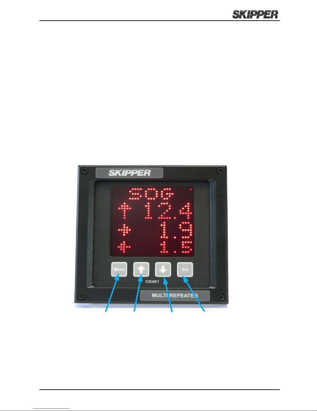
INTRODUCTION. The Multi Repeater
_____________________________________________________________________
The SKIPPER Multi Repeater allow important values from a variety of systems to be
displayed anywhere on the vessel. The Compact is unique in its simple and exible
way to display vital data in almost all conditions, from no light to bright sunlight.
In addition, it is classed to IP 56 allowing it to be mounted outside and used in any
conditions. The unit is a standard 144 mm format allowing it to be mounted in tight
spaces or overhead.
MENU Up (↑)
Down (↓)
SET
Operation and Installation CD401MR-SB
Edition: 2011-12-19 Rev: 1.11Page 8 of 52
CHAPTER 1. Physical installation
____________________________________________________________________
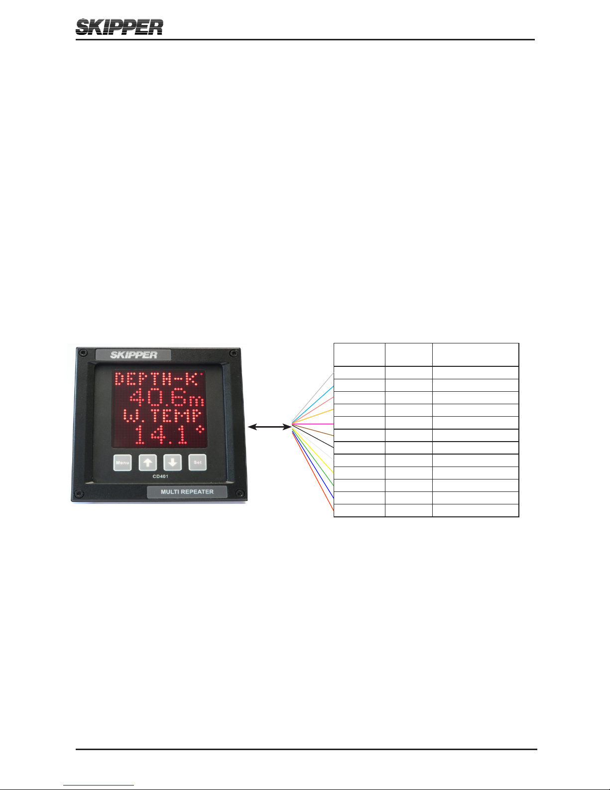
The Multi Repeater CD401MR is a stand alone unit and does not require additional
circuitry. It should be supplied by a 24 V (19 V-36 V) 25 W DC supply and the cabling
of the system is as per diagram below. The unit is supplied with 2 m of cable (12 core).
This can be extended without problem. Only the wires in use need extending.
Note: Mounting drawing is available in Appendix 1.
Colour
Codes
Pin no. Signals
Grey 12 NMEA2 OUT B
Turquoise 11 NMEA2 OUT A
Pink 10 NMEA1 OUT B
Orange 9 NMEA1 OUT A
Violet 8 DIM DWN B
Brown 7 DIM DWN A
Black 6 DIM UP B
White 5 DIM UP A
Yellow 4 NMEA IN B
Green 3 NMEA IN A
Blue 2 0 V
Red 1 +24 V
2 m
Edition: 2011-12-19 Rev: 1.11
Page 9 of 52
Operation and Installation CD401MR-SB
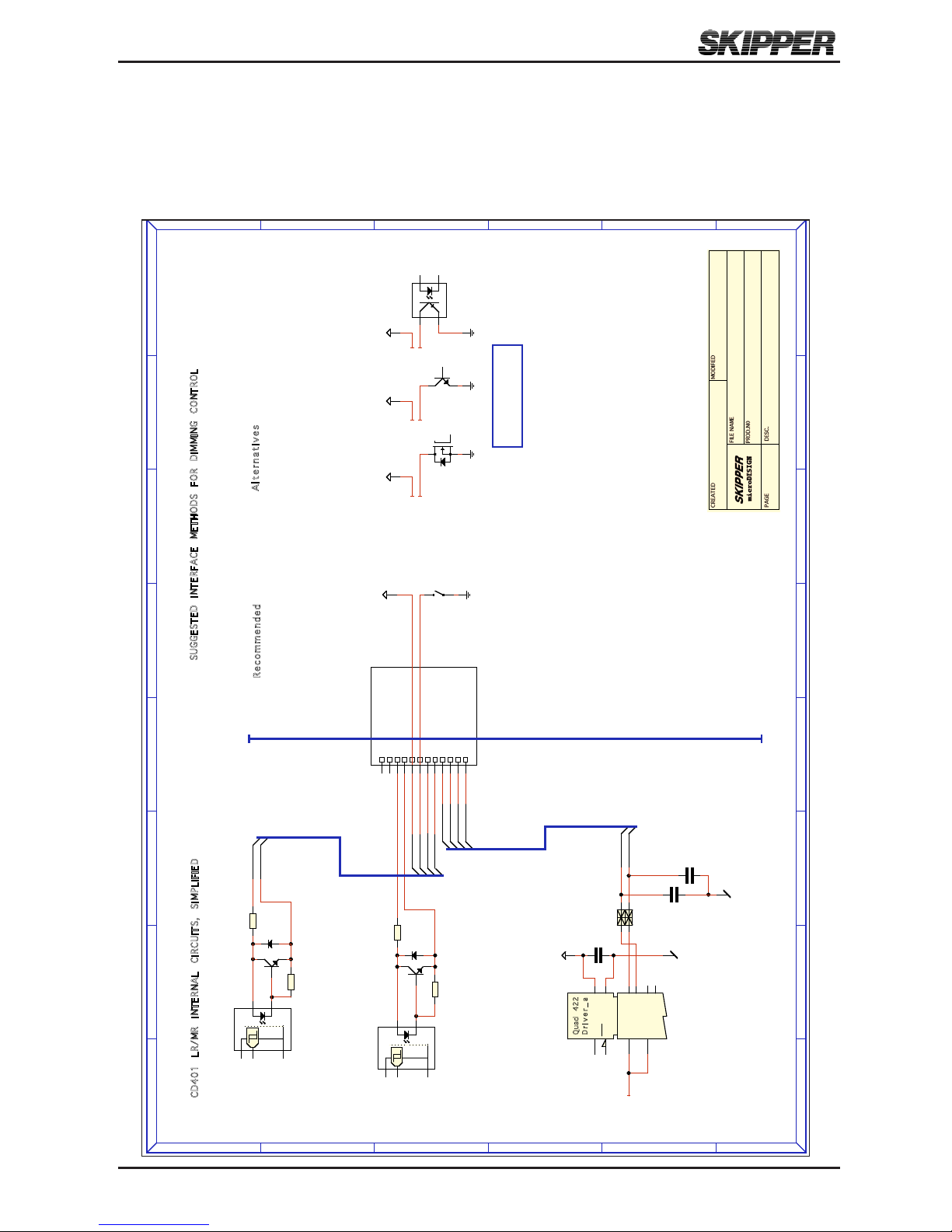
the Dimming inpUts
Pulses of at least 60 ms on the dimming up and dimming down cables will cause the
dimming to change by one level. The inputs are optocoupled and therefore require an
external voltage to operate, (5 Volt -24 Volt (Typically 5/12/24 Volt)).
A
A
B
B
C
C
D
D
E
E
F
F
G
G
H
H
1 1
2 2
3 3
4 4
5 5
6 6
SUGGESTED IN TERFACE M ETHODS FO R DIMMING CO NTROL
All Diming Inputs DIMnnn
Input Voltage VCC 5 - 24 V
CD4 01 LR/ MR INT ERNA L CIRC UITS, SIMPLIFIE D
A lt er nat iv es
Re co mm en de d
2008.11.13 ØK 2010.05.14 ØK
Misc_IO_ExamplesNACD_4015/5
A
B
E
C
BC847A
T400
0805
21
100R
R400
A
CA
a
BAV99
D400
2
3
8
7
5
HCPL0201
PH400
1206
1K0
R401
DIMnnnB
DIMnnnA
B
E
C
G
D
S
1
2
4
3
VCC
VCC VCC VCC
0805
X7R
1
2
100n
21
0805
C0G
2
1
100p
21
BLM21A10
0805
C0G
2
1
100p
ENA
ENA
INA
INB
OUTA+
Q
uad 422
D ri ve r _a
OUTA-
OUTB+
OUTB-
VCC
VSS
4
12
1
7
236
5
16
8
DS26C31TM
+5V
B
E
CBC847A
A
CA
BAV99
2
3
8
7
5
HCPL0201
0805
12
100R
0805
12
300R
NMxOUTB
NMxOUTA
NM2OUTB
NM2OUTA
NM1OUTB
NM1OUTA
DIMDWNB
DIMDWNA
DIMUPB
DIMUPA
NM1OUTB (Pink)
NM1OUTA (Orange)
NMEAINB (Yellow)
NMEAINA (Green)
NM2OUTB (Grey)
NM2OUTA (Turqoise)
+24V (Red)
-24V (Blue)
DIMUPB (Black)
DIMDWNA (Brown)
DIMUPA (White)
DIMDWNB (Violet)
121110
987654321
J101
TJC3_12_90
Operation and Installation CD401MR-SB
Edition: 2011-12-19 Rev: 1.11Page 10 of 52
CHAPTER 2. Setting up and using the
Compact Display
_____________________________________________________________________
principles
The Compact Display is a exible dot matrix LED display designed to display navigation
data. The Multi repeater can be user programmed to show most kinds of numerical data
from NMEA messages. It can also be used as a primary sensor display for speed logs
showing the speed values produced by the sensor. The Compact with its JB60CD box
meets all the requirements of a primary device both functionally and electrically. On
its own it meets the requirements as a repeater. The Compact has three user denable
alphanumeric displays, each allowing up to 4 lines to be displayed. When the device is
used as a primary device, some of these screens will be xed.
rUntime screens
The Compact Display starts up in runtime mode. By pressing the MENU button, the
preset runtime screens can be selected. The unit can be dimmed in any of the runtime
screens using the UP and DOWN buttons.
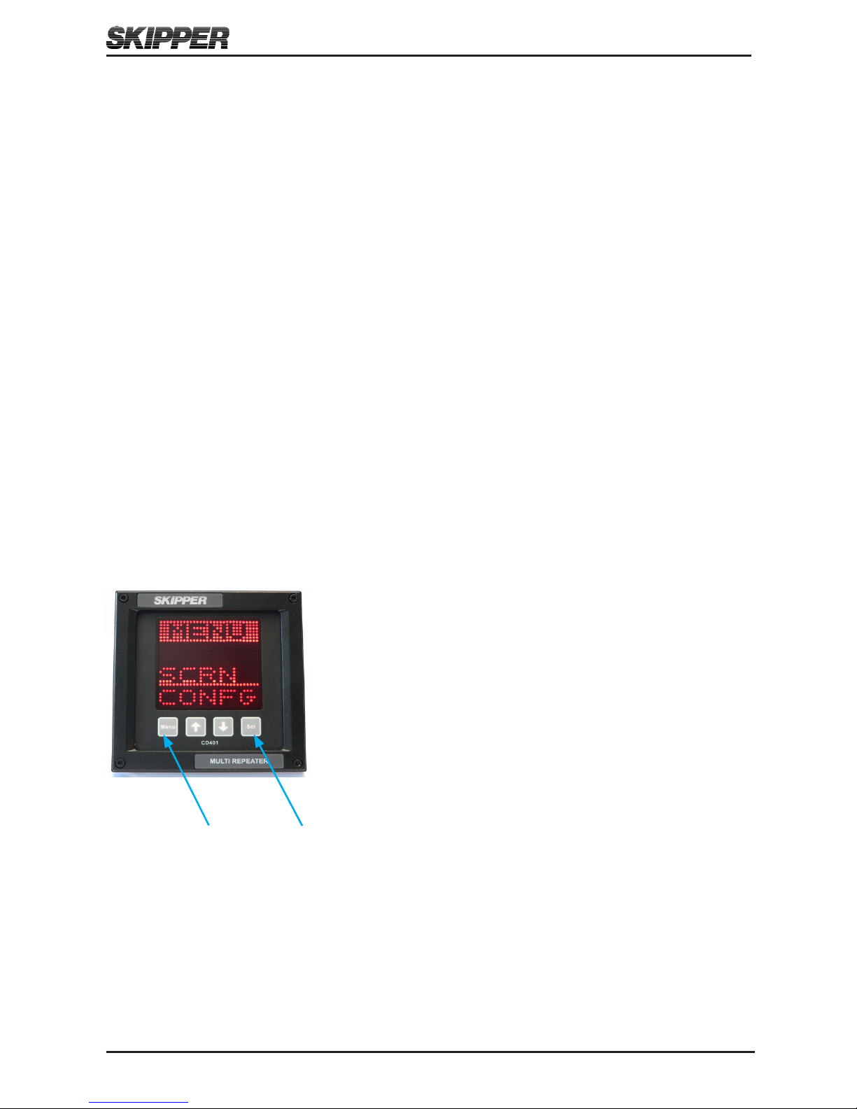
menU screens
To change the setup of the Multi Repeater, the user must simultaneously press MENU
and SET buttons. This will give access to a menu system
allowing the user to scroll up and down the sub menus and
functions using UP , DOWN and SET buttons to select. To
move back up a menu, the MENU button must be pressed.
The middle underlined line is the selected line. The other
lines are dimmed.
The menu structure is shown in the MENU DIAGRAM.
The menus are product dependant, only the relevant menus
are accessible. Some menus are available in all setups.
Press both MENU and SET buttons to activate the menus. Press and hold MENU to
return to runtime screen
shifting screens
The system can be made to shift, with a ve second period, between the activated
screens. Pressing MENU will pause this function, and holding MENU will reactivate it.

Edition: 2011-12-19 Rev: 1.11
Page 11 of 52
Operation and Installation CD401MR-SB
ActivAting the rUntime screens
The system has three user preset runtime screens (SCR1, SCR2, SCR3). The Screen
Menu allows the user to congure and choose which runtime screens to be included in
normal operation. UP and DOWN buttons will scroll to the available screens. By using
the SET button, the user can control each individual screen to ON, OFF or SHIFTING.
Screens set to ON are available to be displayed by pressing the MENU button. Screens
set to OFF will not be displayed. Screens set to SHIFTING will be shown on the
display periodically. Each shifting runtime screen will
be displayed for 5 seconds.
ON
SHIFTING
OFF
If any screens are congured to SHIFTING, these selected screens will automatically
start displaying periodically. The shifting of these preset runtime screens are stopped
if the MENU button is pressed in runtime mode. By holding down the MENU button
longer, the shifting will be started again.
Operation and Installation CD401MR-SB
Edition: 2011-12-19 Rev: 1.11Page 12 of 52
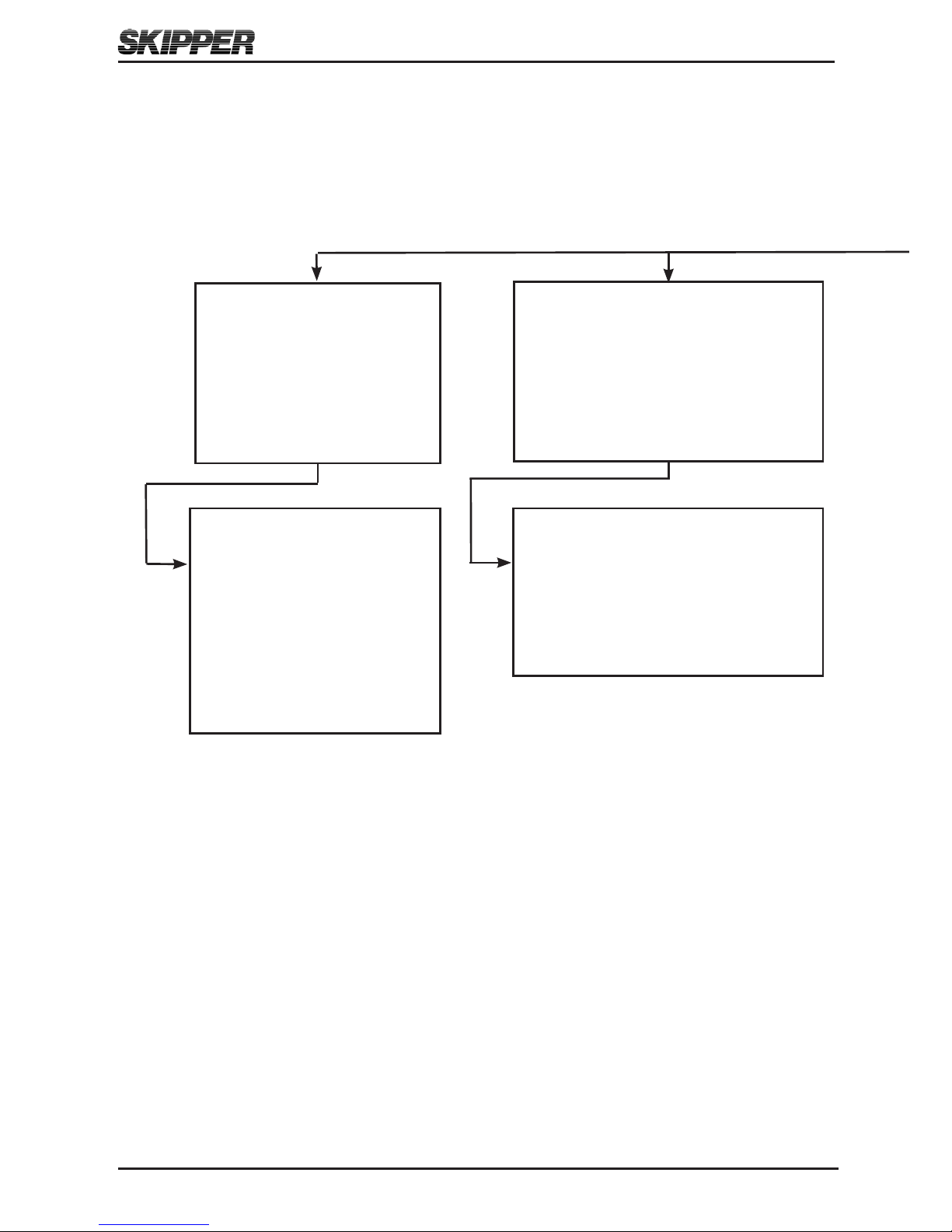
Screens (SCRN)
Select runtime screens
▲ Next sub menu
▼ Prev sub menu
SET select sub menu
MENU return
Screens (SCRN)
▲ Next runtime screen
▼ Prev runtime screen
SET activate/deactivate/
shifting runtime screens
SCR1
SCR2
SCR3
INFO
menU DiAgrAm
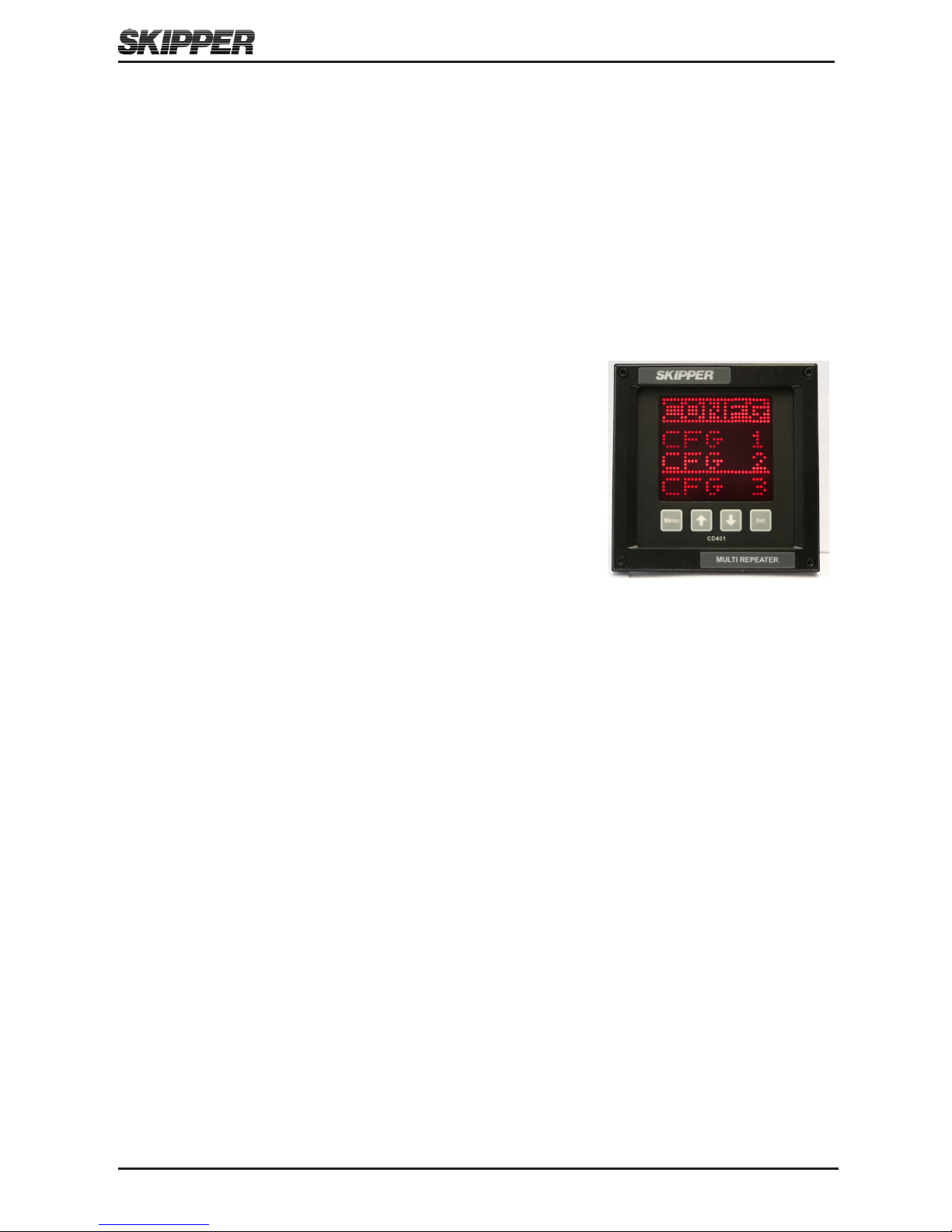
Screen Conguration (CONFG)
Change the messages being
displayed on each user screen
▲ Next sub menu
▼ Prev sub menu
SET select sub menu
MENU return
Cong (CONFG)
▲ Change display message
▼ Change display message
SET move to next position on screen
CFG 1
CFG 2
CFG 3

Edition: 2011-12-19 Rev: 1.11
Page 13 of 52
Operation and Installation CD401MR-SB
System Setup (SETUP)
Setup the system
parameters
▲ Next sub menu
▼ Prev sub menu
SET select sub menu
MENU return
Baud Settings (NMEA)
▲ Higher value
▼ Lower value
Menus, scrollable menu system
Accessed with SET and MENU pressed simultaneously
▲ Next sub menu
▼ Prev sub menu
SET select sub menu
MENU return
Diagnostics Advanced Setup (DIAG)
Diagnose and adjust less used parameters
▲ Next sub menu
▼ Prev sub menu
SET select sub menu
MENU return
Code option activation (CODE)
Shows serial no
Code number with active digit underlined
▲ Increment underlined digit
▼ Move to next digit
SET activates the displayed code
Upgrade mode (UPGRD)
Allow the system to upgrade from cable
Demo (DEMO)
▲ Increment mode
▼ Decrement mode
MENU accept mode
Mode 1 = dynamic
Mode 2 = static
Off
Splash screen (INFO)
▲ Dimming up
▼ Dimming down
Option info
Software version
Self Tests (TEST)
▲ Next test
▼ Previous test
SET starts selected test
NMEA output
Select NMEA outputs
▲ Move to next message
▼ Move to previous message
SET turn on/off current message
IIVDR
PSKPVDR

Operation and Installation CD401MR-SB
Edition: 2011-12-19 Rev: 1.11Page 14 of 52
setUp of inpUts
The system will allow many NMEA formats to be displayed. The system will
automatically update recognized formats.
chAnging of the bAUD rAte
The NMEA (IEC61162-1) standard is 4800 baud. Some vessels run with higher baud
rates. 4800, 9600, 19200, 38400, 57600 and 115200 baud rates can be selected in the
baud screen of the setup menu.
Demo moDe
A demo mode is available, and can be activated with MENU button in the diagnostics
menu. Two modes are available.
• Mode 1 is a dynamic demo mode taking the present value as the start point and
slowly varying all the available values.
• Mode 2 is a static mode taking the present values and keeping them active.
• Mode 3 is a xed speed longitudinal 5 kn, transversal 1 kn.
When the demo mode is active, alarms will be disabled, and the screen will indicate the
demo state with a blinking S in the upper right corner. The user can turn off the demo
mode from the demo screen, or by recycling the power. The demo mode will turn off
automatically after 10 hours.
mAster reset (fActory DefAUlt settings)
The factory default settings can be restored by performing the following operations:
1. Select CODE in diagnostic (DIAG) menu.
2. Press the SET button (Note: Do not change code value).
The unit will now restart with factory default settings.

Edition: 2011-12-19 Rev: 1.11
Page 15 of 52
Operation and Installation CD401MR-SB
CHAPTER 3. Conguring the screens
_____________________________________________________________________
rUntime screens
The unit starts up in runtime mode. By pressing the MENU button, the preset runtime
screens (SCR1, SCR2, SCR3) can be selected. The unit can be dimmed in any of
the runtime screens using the UP and DOWN buttons. If Trip/Total are selected as a
displayed parameter, they can be toggled using the SET button. If wind speed is selected
as a displayed parameter, the unit can be toggled between knots, m/s, or Beaufort using
the SET button.
AccepteD nmeA sentences
When using the Compact Display as a Multi Repeater, the display could be user
programmed to show the most commonly used NMEA 0183 (IEC61162) messages for:
Depth Below surface, keel and transducer
Speed Over ground and through water (longitudinal, transverse, aft and
relative)
Distance Total/trip for both ground and water
Heading True, magnetic and relative
Rotation Rate of turn and direction
Pitch and roll In degrees
Wind Speed and direction (true, magnetic and relative)
Temperature Water and air
Drive RPM (Revolutions Per Minute), propeller pitch and rudder position
Clock UTC (Universal Time Coordinated), local time and Expected Time
of Arrival (ETA)
Dimming Display dimming
Auxillary User dened NMEA messages
A summary of supported NMEA sentences is listed in Appendix 2.
Operation and Installation CD401MR-SB
Edition: 2011-12-19 Rev: 1.11Page 16 of 52
configUrAtion AnD operAtionAl screen
The programming of parameters to show on the screen is very exible. It is advise to
add leading text before the parameters and not mixing to many different messages. A
typical conguration is to show two related parameters on the screen simultaneously
with leading text. Arrows are added to some parameters for better readability. Press
MENU and SET button simultaneously to enter the main menu screen, select CONFG
and then select wanted screen (CFG1, CFG2 or CFG3) to start congure wanted screen.
See chapter 2 ”Setting up and using the Compact Display” on how to program the
display to show wanted information on the screen.
configUring of screens
The 3 user programmable screens can be set up using the
Cong (CONFG) menu. This submenu allows the user to
select one of the three screens, and on entering the Cong
screen, the user can change the data type to be displayed in
each of the 4 screen positions. UP and DOWN will change
the data type, SET will move to the next screen position.
Placing TXT in the bottom 4th line or 3rd and 4th line will cause the data to spread out
showing fewer data points. The system will not allow you to mix speed data from
different sources on the same screen. Having 2 TXT lines after each other will also
rearrange the positioning. (See examples on next page).
The non-active parameters will continue showing the dimmed present data, when not
selected. Some combinations of data are not allowed, as they may cause confusion.
These will be automatically corrected. Note that the leading text is identical for some
data, and information about talkers are ignored. Regulations require the user to be able
to identify which data they are looking at. This can be acheived by using the TXT
function or a sticker on the unit.

Edition: 2011-12-19 Rev: 1.11
Page 17 of 52
Operation and Installation CD401MR-SB
Depth
The NMEA sentences DPT, DBS, DBT, DBK and PSKPDPT are all supported for
receiving information about the depth. The use of the DPT sentence is recommended
when available. Depth values in feet and fathoms (from DBK, DBT and DBS) are
converted to meters. The screen will display either DEPTH-S (depth below surface),
DEPTH-T (depth below Transducer) or DEPTH-K (depth below keel) depending of
the received sentences (DBS, DBT or DBK) or the offset value in DPT. The proprietary
sentence PSKPDPT will also indicate the transducer location with an arrow in the text
line.
The depth is always displayed in meters. Depth values below 10 meters are displayed
with 2 decimals, depth values between 10 and 100 meters are displayed with 1 decimal
and depth above 100 meters are displayed without decimals.
Maximum depth value to be displayed is 9999 meters.
Cong.
screen:
Runtime
screen:

Operation and Installation CD401MR-SB
Edition: 2011-12-19 Rev: 1.11Page 18 of 52
Speed
The NMEA sentence VBW is supported for receiving information about the speed
through water and speed over ground (bottom) for longtiudinal, tranverse and transverse
aft. The NMEA sentences VHW and VTG are supported for receiving information about
relative speed.
• An arrow, indicating the direction, is added in front of the value for speed values
from the NMEA sentences VBW.
• The relative speed through water is fetched from the NMEA sentence VHW.
• The relative speed over ground is fetched from the NMEA sentence VTG.
• Speed value in km/h is converted to knots if speed value in knots is not available.
• Relative speed is displayed without arrows.
• All speed values are displayed in knots with one decimal. Maximum speed value to
be displayed is +/- 99.9 knots.
Cong.
screen:
Runtime
screen:
The Multi Repeater will accept the NMEA sentence VMXDR to change the direction
of the speed through water. Receiving the following NMEA sentence will change the
direction of the STW:
$VMXDR,A,180,D,SPDD*hh<CR><LF>
An arrow symbol is added in front of the STW text to indicate that the speed direction
is reversed. Receiving the following NMEA sentence will change the direction of the
STW back to normal:
$VMXDR,A,0,D,SPDD*hh<CR><LF>
The VMXDR sentence must be valid together with the VBW sentence.

Edition: 2011-12-19 Rev: 1.11
Page 19 of 52
Operation and Installation CD401MR-SB
The Compact Multi Repeater Backwards (CD MB) will display the arrow symbol in
both directions if VMXDR with speed direction information is received. Note that
the Compact Multi Repeater Backwards already displays the STW speed in opposite
direction, so receiving information about reverse speed will again turn the speed
direction with 180 degrees.
Screen with arrow symbol in reverse direction:
Distance
The NMEA sentence VLW are supported for receiving information about distances. The
Trip/Total parameters for either water distance or ground distance can be toggled using
the SET button.
The distance values are always displayed in nautical miles and the value will wrap
around after reaching the maximum value of 99999. Total/trip values below 10 are
displayed with two decimals, values between 10 and 1000 with one decimal and values
above 1000 are displayed with no decimals.
Conguration
screen:
Runtime screen:

Operation and Installation CD401MR-SB
Edition: 2011-12-19 Rev: 1.11Page 20 of 52
Heading
The NMEA sentences VHW, VTG, THS, HDT, HDM and HDG are all supported for
receiving information about the heading. It is recommended to use THS instead of HDT
and HDG instead of HDM when available. The deviation and variation parameters in
HDT are ignored.
If the same heading parameter is received from different talkers, the heading parameter
will be prioritized as shown below:
1. Gyro, north seeking (HE).
2. GPS (GP).
3. Compass, magnetic (HC).
4. Others.
An arrow is added on the text line to indicate which direction the bow turns. If no
change in heading from previous value, no arrow is displayed.
The heading value is always displayed with one decimal. Legal range for the heading to
be displayed, are values in the range from 0 to 359.9 o.
Cong.
screen:
Runtime
screen:
Direction of turn is to
port.
Direction of turn is to
starboard.
No change in
heading since last
message.

Edition: 2011-12-19 Rev: 1.11
Page 21 of 52
Operation and Installation CD401MR-SB
Rotation
The NMEA sentence ROT is supported for receiving information about the rotation. A
steady arrow is added on the text line to indicate which direction the bow turns.
• A positive received value indicates that bow turns to starboard and an arrow to the
right is displayed.
• A negative received value indicates that bow turns to port and an arrow to the left
is displayed.
• A value of zero indicates no rotation and no arrow is displayed.
Values below 99.9 are displayed with one decimal. Values above 100 are displayed with
no decimals. Maximum value to display is +/- 999O/min.
Conguration
screen:
Runtime screen:

Operation and Installation CD401MR-SB
Edition: 2011-12-19 Rev: 1.11Page 22 of 52
Pitch and Roll
The NMEA sentence XDR, version B is supported for receiving information about the
Pitch and Roll.
• A positive received value for Pitch indicates that the bow is up and negative if bow
is down.
• A positive received value for Roll indicates that port is up and starboard is down, a
negative value indicates that starboard is up and port is down.
Values below 10 degrees are displayed with two decimals and values above 10 degrees
with one decimal. Maximum value to be displayed is +/- 359.9O.
Conguration
screen:
Runtime screen:

Edition: 2011-12-19 Rev: 1.11
Page 23 of 52
Operation and Installation CD401MR-SB
Wind
The NMEA sentences MWV, VWR, VWT and MWD are all supported for receiving
information about the wind speed and direction. MWV is recommended instead of
VWR and VWT, when available. All wind speed units are accepted (knots (N), m/s (M)
and km/h (K)) and converted to wanted speed units to display on the sceen. Speed units
on the display may be toggled between kn (knots), m/s and Bft (Beaufort) by pressing
the SET-button.
A graphical representation of the wind angle is displayed if the following parameters
are selected:
• TXT must be selected for the rst two parameters.
• One wind angle must be selected.
• Corresponding wind speed from the same NMEA sentence could be selected.
Otherwise TXT must be selected.
• The wind angle is represented by an arrow on the screen.
See chapter 2 ”Setting up and using the Compact Display” for details how to set up the
screen.
The range of values to be displayed, are:
• Speed: 0 - 99.9 knots.
• Heading: 0 – 359.9
O.

Operation and Installation CD401MR-SB
Edition: 2011-12-19 Rev: 1.11Page 24 of 52
Cong.
screen
:
Runtime
screen:
SET button has been
pressed for toggling
the speed units to
m/s.
Conguration
screen:
Graphical
representation
Runtime
screen:
SET button has been pressed for changing between knots, m/s
and Beaufort units.
Wind, (continued from previous page):

Edition: 2011-12-19 Rev: 1.11
Page 25 of 52
Operation and Installation CD401MR-SB
Temperature
The NMEA sentences MTA, MTW and MDA are supported for receiving information
about the air (MTA or MDA) and water (MTW) temperatures. Air temperature from
MDA is used if data from MTA is not available.
Temperatures are displayed in degree Celcius. Values below 10 degrees are displayed
with two decimals and values above 10 degrees with one decimal. The maximum/
minimum temperatures to be displayed are +/- 99.9 oC.
Conguration
screen
:
Runtime screen:

Operation and Installation CD401MR-SB
Edition: 2011-12-19 Rev: 1.11Page 26 of 52
Drive
• The NMEA sentence RPM is supported for receiving information about the speed
revolutions (rev/min) and propeller pitch (% of maximum).
• The NMEA sentence RSA is supported for receiving information about the rudder
angle.
The speed revolution values below 999.9 is displayed with one decimal and values
above 1000 is displayed without decimals. Propeller pitch values below 10 degrees are
displayed with two decimals and values above 10 degrees with one decimal.
• Max./min. value to be displayed for speed revolution is +/- 9999 rev/min.
• Max./min. value to be displayed for propeller pitch is +/- 100 %.
• Max./min. value to be displayed for rudder angle is +/- 359.9 o.
Conguration
screen:
Runtime screen:

Edition: 2011-12-19 Rev: 1.11
Page 27 of 52
Operation and Installation CD401MR-SB
Clock/UTC
The UTC is fetched from either of the NMEA sentences ZTG, ZDA, GGA or RMC,
prioritized in the same order. The NMEA sentences ZDA is used for receiving information
about the local time. The NMEA sentences ZTG is used for receiving information about
expected time of arrival. Maximum offset for displayed time of ”Expected Time of
Arrival” is 24 hours. All time values are displayed with the format hh:mm, where hh are
hours and mm are minutes.
Cong.
screen:
Runtime
screen:
Local time is
UTC – (1h 30 min).
Expected Time of
Arrival is UTC +
(20h 45 min).
Display Dimming Control
The brightness of the display can be controlled by the NMEA sentence DDC. Note
that the brigthness also can be controlled by buttons on the display and remote dimmer
control (IR30DIM). Both the Brigthness Percentage and Display Dimming Preset are
supported in the NMEA sentence DDC. (See Appendix 2).

Operation and Installation CD401MR-SB
Edition: 2011-12-19 Rev: 1.11Page 28 of 52
Auxillary
A proprietary NMEA sentence is supported which allow the user to dene up to 4
additional parameters to be displayed from any specied NMEA sentence(s). This
proprietary NMEA sentence has the following format:
$PSKPPCCPNMEA, <Auxillary number>,<Header>,<Data Field number.>,<Type>,
< Status eld number >,< Status valid character >,<Text>*hh<CR><LF>
Example: Fetch a propritary NMEA sentence for roll & pitch and display the values:
$PPPRP,<a>,<b><CR><LF> where <a> is roll data parameter and <b> is pitch data
parameter.
Fetch also the parameters for both port and starboard rudder angle from the following
NMEA message: $SGRSA,<a>,A,<b>,A<CR><LF> where <a> is starboard rudder
sensor and <b> is port rudder sensor and ’A’ is status for each corresponding data eld
parameter. The following NMEA sentences must be sendt to the Compact display to
accept these parameters:
$PSKPPCCPNMEA,1,PPPRP,0,8,,ROLL<CR><LF>
$PSKPPCCPNMEA,2,PPPRP,1,8,,PITCH<CR><LF>
$PSKPPCCPNMEA,3,SGRSA,0,8,1,A,SRUD<CR><LF>
$PSKPPCCPNMEA,4,SGRSA,2,8,3,A,PRUD<CR><LF>
Select the AUX1 in the meny to display the roll parameter, select the AUX2 in the
meny to display the pitch parameter, select AUX3 in the menu to display the starboard
rudder angle and AUX4 in the menu to display the port rudder angle.
Conguration screen:
Runtime screen:
Received NMEA sentence:
$PPPRP,12.31,1.22 $SGRSA,3.4,A,0.2,A

Edition: 2011-12-19 Rev: 1.11
Page 29 of 52
Operation and Installation CD401MR-SB
error hAnDling
All parameters within each NMEA sentences are checked for checksum, legal range,
validity and timeout.
Bad checksum ( - - - - -)
If the Checksum Field (*hh) is present, the value is checked. The screen will indicate
bad checksum by displaying minus signs instead of the value (- - - - -). If no Checksum
Field is present, no checking is performed.
Illegal range and validity (. . . . .)
Some values must be within a range. If a value is out of range, the following exception
is performed:
• Wrap around: The displayed value will start from zero again after reaching
the maximum/minimum value (Trip values, only).
• Limited value: The maximum or minimum value will be displayed (Speed
and temperature values).
• Illegal value: The value has no meaning (ex. heading values above 360O). The
screen will indicate illegal value by displaying dots instead of the value (. . . .).
A Null eld is a eld in the NMEA sentence without any character between two delimiter
characters. A Null eld indicates that the value is unreliable or not available. The screen
will indicate a Null eld by displaying dots instead of the value (. . . . . ) if no value is
received within the timeout timeframe.
Some parameters has a status parameters associated with them (A = data valid, V = data
invalid). The screen will indicate an invalid parameter by displaying dots instead of the
value (. . . . .) if no new valid value is received within the timeout timeframe.
Timeout (ERROR)
The timeout value for each parameter within each NMEA sentence is 10 seconds. The
screen will indicate timeout by displaying an error message (ERROR) if no new value
is received within the timeout timeframe.

Operation and Installation CD401MR-SB
Edition: 2011-12-19 Rev: 1.11Page 30 of 52
CHAPTER 4. Maintenance
_____________________________________________________________________
roUtine mAintenAnce
No maintenance is required. The screen can be cleaned with a soft cloth.
checking yoUr version
If the Info screen is activated on the run screens, the system type and rmware version
can be read from there. Otherwise the same screen can be obtained in the diagnostics
menu. The system type will be one of the following:
CD E1 Compact display EML 1 Axis.
CD E2 Compact display EML 2 Axis.
CD EB Compact display EML 2 Axis backwards.
CD LR Compact display Log Repeater.
CD MR Compact display Multi Repeater.
CD MB Compact display Multi Repeater backwards.
The system will be locked to one of these setups, but can be changed to one of the other
systems (with an additional cost) using a code (see Appendix 4).
firmwAre UpgrADe
The system is undergoing continuously improvements, and periodically new rmware
will be released. A chip can be supplied (with an additional cost) with the new
software. This is changed by removing the backplate of the Compact display.
moUnting the mUlti repeAter fAcing Aft.
The Compact Display could also be set up to operate in ”Multi Repeater,
Backwards” mode. In this mode all speeds are in opposite direction. See the section
”MAINTENANCE” on how to change the system setup. The parameters in ”Multi
Repeater, Backwards” mode will be replaced according to the following:
STWWL = - STWWL SOGBL = - SOGBL
STWWT = - STWWA SOGBT = - SOGBA
STWWA = - STWWT SOGBA = - SOGBT

Edition: 2011-12-19 Rev: 1.11
Page 31 of 52
Operation and Installation CD401MR-SB
APPENDIX 1.
specificAtions AnD mechAnicAl DrAwing
_____________________________________________________________________
system specificAtion
Power Supply DC: 19 - 36 V/25 Watt.
Display 28 x 30 pixel, Alphanumeric LED (red). With dimming.
Languages English.
Accessories Dimming control.
Classication IMO MED B.
Service Available in most major harbours, world-wide through extensive
dealer network. See www.skipper.no for further information.
DisplAy
Weight (display) 1.3 kg.
Cable length 2 m (can be extended).
Compass safe distance (min) 30 cm.
User adjustable screens 3
Parameters per screen 2 with text, 3 with single text line.
inpUts/oUtpUts
Outputs 2 x NMEA (IEC61162-1) (2007).
Inputs 1 x NMEA (IEC61162-1) (2007).
External Dimming (up and down pulses).

Operation and Installation CD401MR-SB
Edition: 2011-12-19 Rev: 1.11Page 32 of 52
Menu
Menu Set
1
2
3
4
144 [5,669]
Power consuption: 24 VDC/ 3W
Protection code: IP56
COMPACT DISPLAY
SKIPPER
8
.....
Set
mechAnicAl Dimentions

Edition: 2011-12-19 Rev: 1.11
Page 33 of 52
Operation and Installation CD401MR-SB
APPENDIX 2.
AccepteD nmeA 0183 sentences sUmmAry
NMEA
Sentence
Description Parameter
Name
Screen
name
Depth
DPT Water Depth in meters DPT DEPTH-K
DEPTH-T
DEPTH-S
DBK Water Depth below Keel in meters DBK DEPTH-K
DBT Water Depth below Transducer in meters DBT DEPTH-T
DBS Water Depth below Surface in meters DBS DEPTH-S
PSKPDPT SKIPPER proprietary depth sentence PDPT DEPTH-K
DEPTH-T
DEPTH-S
Speed
VBW Longitudinal Water Speed STWWL STW
Transverse Water Speed STWWT STW
Transverse Water Speed, Aft STWWA STW
Longitudinal Ground Speed SOGBL SOG
Transverse Ground Speed SOGBT SOG
Transverse Ground Speed, Aft SOGBA SOG
VHW Speed Through Water in knots, relative STW-R STW-R
VTG Speed over Ground in knots, relative SOG-R SOG-R
XDR Water Speed direction - -
Distance
VLW Water-track Distance since reset TRIPW TRIPW
Water-track Total distance TOTLW TOTLW
Bottom-track Distance since reset TRIPB TRIPB
Bottom-track Total distance TOTLB TOTLB
Heading. VHW Heading, degrees, true HDW-T HDG.T
Heading, degrees, magnetic HDW-M HDG.M
VTG Heading (Course Over Ground), degrees,
true
COG-T COG.T
Heading (Course Over Ground), degrees,
magnetic
COG-M COG.M
THS Heading, degrees, true THS HDG.T
HDT Heading, degrees, true HDT HDG.T
HDM Heading, degrees, magnetic HDM HDG.M
HDG Heading, degrees, magnetic HDG HDG.M

Operation and Installation CD401MR-SB
Edition: 2011-12-19 Rev: 1.11Page 34 of 52
NMEA
Sentence
Description Parameter
Name
Screen
name
Rotation
ROT Rate of Turn in degrees/minute ROT ROT
Pitch and
roll
XDR Pitch PITCH PITCH
Roll ROLL ROLL
Wind
MWV Wind angle, Theoretical (True) MWVAT WIND-T
Wind angle, Relative MWVAR WIND-R
Wind Speed in knots MWVNT WIND-T
Wind speed in m/s MWVMT WIND-T
Wind speed in Beaufort MWVBT WIND-T
Wind Speed in knots MWVNR WIND-R
Wind speed in m/s MWVMR WIND-R
Wind speed in Beaufort MWVBR WIND-R
VWR Wind angle, Relative VWR-A WIND-R
Wind Speed in knots VWR-N WIND-R
VWT Wind angle, True VWT-A WIND-T
Wind Speed in knots VWT-N WIND-T
MWD Wind angle, True MWD-T WIND-T
Wind angle, Magnetic MWD-M WIND.M
Wind Speed in knots MWD-N WIND
Temp. MTA, MDA Air Temperature in degree Celcius ATEMP AIRTEMP
MTW Water Temperature in degree Celcius WTEMP W.TEMP
Drive
RPM Revolutions / min RPM RPM
Propeller Pitch (% of maximum) PPTCH P.PITCH
RSA Rudder Sensor Angle RSA RUDDER
Clock/
UTC
ZTG, ZDA,
GGA, RMC
UTC (hh:mm) UTC UTC
ZDA Local Time (hh:mm) LOC LOC
ZTG Expected Time of Arrival (UTC) (hh:mm) ETA E TA
Display
dimming
DDC Display Dimming Control

Edition: 2011-12-19 Rev: 1.11
Page 35 of 52
Operation and Installation CD401MR-SB
NMEA
Sentence
Description Parameter
Name
Screen
name
Auxillary
Dened by
proprietary
NMEA
sentence
User dened message 1 (Auxillary 1) AUX1 Dened by
proprietary
NMEA
sentence
User dened message 2 (Auxillary 2) AUX2
User dened message 3 (Auxillary 3) AUX3
User dened message 4 (Auxillary 4) AUX4
DetaileD Description
Depth:
Parameter
name
Depth
$--DPT, x.x, x.x*hh<CR><LF>
DPT
Offset from transducer, in meters (see Note 1)
Water depth relative to the transducer, in meters
Depth Below Surface
$--DBS, x.x, f, x.x, M, x.x, F*hh<CR><LF>
DBS
Water depth relative to the surface, in fathoms
Water depth relative to the surface, in meters
Water depth relative to the surface, in feet
Depth Below Transducer
$--DBT, x.x, f, x.x, M, x.x, F*hh<CR><LF>
DBT
Water depth relative to the transducer, in fathoms
Water depth relative to the transducer, in meters
Water depth relative to the transducer, in feet
Depth Below Keel
$--DBK, x.x, f, x.x, M, x.x, F*hh<CR><LF>
DBK
Water depth relative to the keel, in fathoms
Water depth relative to the keel, in meters
Water depth relative to the keel, in feet
SKIPPER Proprietary sentence
$--PSKPDPT,x.x,x.x, , , ,c-c*hh<CR><LF>
PDPT
Transducer location (FWD/AFT/PORT/STB)
Offset from transducer, meters (see Note 1)
Water depth relative to transducer, meters
Note 1: Positive value indicates distance from transducer to water line.
Negative value indicates distance from transducer to keel.

Operation and Installation CD401MR-SB
Edition: 2011-12-19 Rev: 1.11Page 36 of 52
Speed:
Parameter
name
Dual Ground/Water Speed
$--VBW,x.x, x.x, A, x.x, x.x, A, x.x, A, x.x, A*hh<CR><LF>
Status, stern ground speed
A= data valid, V= data invalid
Stern transverse ground speed, in knots SOGBA
Status, stern water speed.
A= data valid, V= data invalid
Stern transverse water speed, in knots
STWWA
Status, ground speed
A= data valid, V= data invalid
Transverse ground speed, in knots SOGBT
Longitudinal ground speed, in knots SOGBL
Status, water speed.
A= data valid, = data invalid
Transverse water speed, in knots STWWT
Longitudinal water speed, in knots STWWL
Water Speed and Heading
$--VHW, , , , , x.x, N, x.x, K*hh<CR><LF>
Relative water speed, in km/h STW-R
Relative water speed, in knots
Course Over Ground and Ground Speed
$--VTG, , , , , x.x, N, x.x, K,*hh<CR><LF>
Relative ground speed, in km/h SOG-R
Relative ground speed, in knots
Speed direction
$VMXDR,A,x.x,D,SPDD*hh<CR><LF>
Transducer ID must be SPDD
Units of measure, D = degrees
Measurement data for speed direction
must be either 0 or 180
Transducer type must be A
(Angular displacement)
Distance:
Parameter
name
Dual Ground/Water Speed
$--VLW, x.x, N, x.x, N, x.x, N, x.x, N*hh<CR><LF>
Ground distance since reset TRIPB
Total cumulative ground distance TOTLB
Water distance since reset TRIPW
Total cumulative water distance TOTLW
Note: All distance values must be specied in nautical miles.

Edition: 2011-12-19 Rev: 1.11
Page 37 of 52
Operation and Installation CD401MR-SB
Heading:
Parameter
name
Water Speed and Heading
$--VHW, x.x, T, x.x, M, , , ,*hh<CR><LF>
Heading, degrees magnetic
HDW-M
Heading, degrees true
HDW-T
Course Over Ground and Ground Speed
$--VTG, x.x, T, x.x, M, , , ,*hh<CR><LF>
Course over ground, degrees magnetic
COG-M
Course over ground, degrees true
COG-T
True Heading and Status
$--THS, x.x, a*hh<CR><LF>
Mode indicator (see Note)
Heading, degrees true
THS
Note: The Mode indicator is ignored
Heading True
$--HDT, x.x, T*hh<CR><LF>
Heading, degrees true
HDT
Heading Magnetic
$--HDM, x.x, M*hh<CR><LF>
Heading, degrees magnetic
HDM
Heading, Deviation and Variation
$--HDG, x.x, , , ,*hh<CR><LF>
Magnetic sensor heading, degrees
HDG
Rotation:
Parameter
name
Rate Of Turn
$--ROT, x.x, A*hh<CR><LF>
Status: A=data valid, V=data invalid
Rate of turn (
O
/min), ”-” = bow turns to
port
ROT

Operation and Installation CD401MR-SB
Edition: 2011-12-19 Rev: 1.11Page 38 of 52
Pitch and Roll
Parameter
name
Transducer Measurements
$--XDR, a, x.x, D, PTCH, a, x.x, D, ROLL*hh<CR><LF>
Transducer ID must be set to ROLL
Units of measure, D = degrees
Measurement data for Roll ROLL
Transducer type must be set to A
(Angular displacement)
Transducer ID must be set to PTCH
Units of measure, D = degrees
Measurement data for Pitch
PITCH
Transducer type must be set to A
(Angular displacement)
Wind:
Parameter
name
Wind Speed and Angle
$--MWV, x.x, a, x.x, a, A*hh<CR><LF>
Status, A = data valid, V = data invalid
Wind speed units,
K = km/h
M = m/s
N = knots
MWVNT
MWVMT
MWVBT
MWVNR
MWVMR
MWVBR
Wind speed
Reference,
R = relative
T = true
Wind angle, 0
O
to 359
O
MWVAT
MWVAR
Relative Wind Speed and Angle
$--VWR, x.x, a, x.x, N, x.x, M, x.x, K*hh<CR><LF>
Wind speed in km/h
VWR-N
Wind speed in m/s
Wind speed in knots
Left/right L/R of vessel heading
VWR-A
Wind angle relative to the vessel, 0 to
180
o
True Wind and Speed Angle
$--VWT, x.x, a, x.x, N, x.x, M, x.x, K*hh<CR><LF>
Wind speed in km/h
VWT-N
Wind speed in m/s
Wind speed in knots
Left/right L/R of vessel heading
VWT-A
Wind angle relative to the vessel, 0 to
180
o

Edition: 2011-12-19 Rev: 1.11
Page 39 of 52
Operation and Installation CD401MR-SB
Wind:
Parameter
name
Wind Direction and Speed
$--MWD, x.x, T, x.x, M, x.x, N, x.x, M*hh<CR><LF>
Wind speed, m/s
MWD-N
Wind speed, knots
Wind direction, 0 to 359 degrees
Magnetic
MWD-M
Wind direction, 0 to 359 degrees True
MWD-T
Temperature:
Parameter
name
Air Temperature
$--MTA, x.x, C*hh<CR><LF>
Temperature, degree C
ATEMP
Meteorological Composite
$--MDA, , , , , x.x, C, , , , , , , , , , , , , ,*hh<CR><LF>
Air temperature, degree C
ATEMP
Water Temperature
$--MTW, x.x, C*hh<CR><LF>
Temperature, degree C
WTEMP
Drive:
Parameter
name
Revolutions
$--RPM, , ,x.x, x.x, A*hh<CR><LF>
Status: A=data valid, V=data invalid
Propeller pitch, % of max, ”-”=astern
PPTCH
Speed, revolutions/min, ”-” counter
clockwise
RPM
Rudder Sensor Angle
$--RSA, x.x, A, , hh<CR><LF>
Status: A=data valid, V=data invalid
Rudder sensor
RSA

Operation and Installation CD401MR-SB
Edition: 2011-12-19 Rev: 1.11Page 40 of 52
Clock / UTC
Parameter
name
UTC & Time to Destination Waypoint
$--ZTG, hhmmss.ss, hhmmss.ss,*hh<CR><LF>
Time-to-go (max 24 h)
ETA
UTC of observation
UTC
Time & Date
$--ZDA, hhmmss.ss, , , , x.x, x.x*hh<CR><LF>
Local zone minutes, 00 to +59
LOC
Local zone hours, 00 to +/- 13
UTC of observation
UTC
Global Positioning System Fix Data
$--GGA, hhmmss.ss, , , , , , , , , , , , ,*hh<CR><LF>
UTC of position
UTC
Recommended Minimum Specic GNSS Data
$--RMC, hhmmss.ss, , , , , , , , , , ,*hh<CR><LF>
UTC of position
UTC
Display Dimming:
Display Dimming Control
$--DDC, a, xx,*hh<CR><LF>
Brigthness Percentage:
00 (min) to 99 (max)
Display Dimming Preset:
D = Day time setting (max)
K = Dusk setting
N = Nigth time setting
O = Backligth off setting (min)

Edition: 2011-12-19 Rev: 1.11
Page 41 of 52
Operation and Installation CD401MR-SB
Auxillary:
SKIPPER proprietary
$PSKPPCCPNMEA, <Auxillary number>,<Header>,<Data Field number.>,<Type>,
< Status eld number >,< Status valid character >,<Text>*hh<CR><LF>
<Auxillary number> The auxillary number for the wanted user dened parameter. Each
additional parameter must be dened with an unique auxillary number.
Legal values are 1, 2, 3 or 4.
<Header> This character string follows the ’$’-sign in the specied NMEA
sentence. Up to 15 characters could be dened here.
<Data eld number> Field number for the data to receive within the specied NMEA sentence,
starting with 0 after the rst eld delimiter. Legal values will be limited
by the maximum number of characters in a NMEA sentence.
<Type> Data type of the parameter. The following data types are dened:
0: Unsigned value
1: Signed value
2: Depth in meters
3: Speed without arrow and postx
4: Longitudinal speed with arrow
5: Transverse speed with arrow
6: Speed with knots as postx
7: Heading with arrow to indicate the direction the bow turns
8: Heading / Direction without arrow
9: Rotation
10: Temperature
11: Percentage
See table of summary of supported data types for user dened messages
<Status eld number.> Field number for status within the specied NMEA sentence, starting
with 0 after the rst eld delimiter. Legal values will be limited by the
maximum number of characters in a NMEA sentence.
<Status valid character> The valid character for the status eld is dened here. The data in the
data eld will only be valid if the staus eld contains this specied
character. A Null eld indicates that the status eld is not used and the
recieved parameter data is always valid.
<Text> Character string to be displayed if text (TXT) is selected. Only large
english characters are accepted. The string can be up to 5 characters long,
but limited to 3 characters for some types, see the description <Type >
for limitations.
The text is truncated if more characters are dened. A Null eld is
interpreted as blank text.

Operation and Installation CD401MR-SB
Edition: 2011-12-19 Rev: 1.11Page 42 of 52
Summary of supported Data Types for User dened messages:
Data
Type
No.
Data
Type
name
Legal Data Type
Range
Screen output
Format / Comments
Out of range
(screen)
Within Range
Min. Max. Below Above Pre-xPost-
x
0 Unsigned
value
-99999.99 99999.99 ’.....’ ’.....’ None None Values between 0 and 9.99
are displayed with 2 decimals.
Values between 10 and 99.9 are
displayed with one decimal.
Values above 100 are displayed
without decimals.
1 Signed value - 9999.99 9999.99 ’.....’ ’.....’ None
or’ – ’
None
2 Depth in
meters
0 9999.99 ’.....’ ’9999’ None ’ m ’
3 Speed
without arrow
and postx
- 99.9 99.9 ’99.9’ ’99.9’ None None All speed values in knots with
one decimal. Negative values are
displayed without minus sign.
4 Longitudinal
speed with
arrow
- 99.9 99.9 ’99.9’ ’99.9’ ’ ↑ ’or
’ ↓ ’
None All speed values in knots with
one decimal. Negative values
indicates astern direction.
5 Transverse
speed with
arrow
- 99.9 99.9 ’99.9’ ’99.9’ ’ → ’or ’
← ’
None All speed values in knots with
one decimal. Negative values
indicates port direction.
6 Speed with
knots as
postx
- 99.9 99.9 ’99.9’ ’99.9’ None ’ kn ’ All speed values in knots with
one decimal. Negative values are
displayed without minus sign.
7 Heading
with arrow to
indicate the
direction the
bow turns
0 360 ’.....’ ’.....’ None ’
O
’ All values are displayed with
one decimal. An arrow (’←’ or’
→’) is added in the text line to
indicate direction the bow turns.
The <Text> eld must therefore
be limited to 3 characters for
this type. The direction of turn
is calculated based on previous
heading value.
8 Heading /
Direction
without arrow
0 360 ’.....’ ’.....’ None
’ O
’ All values are displayed with one
decimal.
9 Rotation - 999 999 ’.....’ ’.....’ None
’ O
/m ’ Values below 99.9 are displayed
with one decimal. Values above
100 are displayed with no
decimals. An arrow (’←’ or’
→’) is added in the text line
to indicate which direction the
bow turns. The <Text> eld
must therefore be imited to
3 characters for this type. A
negative value indicates port
direction.
10 Temperature - 99.99 99.9 ’-99.9’ ’99.9’ None or
’ – ’
’ O
’ Values between 0 and 9.99 are
displayed with 2 decimals. Values
between 10 and 99.9 are displayed
with one decimal.
11 Percentage -100 100 ’.....’ ’.....’ None
or’ – ’
’ % ’ Values between 0 and 9.99 are
displayed with 2 decimals. Values
between 10 and 99.9 are displayed
with one decimal.

Edition: 2011-12-19 Rev: 1.11
Page 43 of 52
Operation and Installation CD401MR-SB
APPENDIX 3.
other options with the mUlti repeAter
_____________________________________________________________________
compAct options
The Compact Display can be set up for one of the following systems:
LR Speed Repeater
E1 (EML124 Compact) Single Axis EML With Electronic unit (JB60CD),
sensor and cables
E2 (EML224 Compact) Dual Axis EML With Electronic unit (JB60CD),
sensor and cables
EB (EML224 Compact) Dual Axis EML
Backwards
With Electronic unit (JB60CD),
sensor and cables
MR Multi Repeater
MB Multi Repeater
Backwards
• Speed Repeater: A simple repeater for speed in 1 and 2 axis and trip. Limited
functionality.
• Single Axis EML: As above plus primary display for speed logs showing
longitudinal speed values produced by the sensor.
• Dual Axis EML: As above, but showing both longituional and transverse
speed values produced by the sensor.
• Dual Axis EML Backwards: As above, but can be connected to an external
switch for showing the speeds in opposite direction.
• Multi Repeater: A comprehensive repeater for many of the most common
used NMEA messages. Functions also for user dened messages.
• Multi Repeater Backwards: As above, but the speeds are shown in opposite
direction.
The software for all these systems is stored in the ash memory and the system
conguration can be changed using a security code. This code can be obtained from
www.skipper.no. By sending an order to SKIPPER together with the systems serial
number. (Obtained by opening the code screen in diagnostics). On entering the
supplied code number, the system options will be set. Please note that the cabling is
different for repeaters and speed logs, so these are not compatible without replacing
the back plate.

Operation and Installation CD401MR-SB
Edition: 2011-12-19 Rev: 1.11Page 44 of 52
chAnging the system/ADDing options
The Compact display unit is being developed as a low cost display alternative to full
graphics displays already available. Most extra features are available for the Compact
and these can be activated using the CODE page in the DIAG menu. On this menu,
the systems unique ID is displayed, and the new options can be purchased from the
SKIPPER retailer to add extra functions. You will receive a code to be entered into the
CODE page by using the arrow buttons.
NOTE: It is important to note that pay option codes are unique for each individual
unit and will not work on other units.
DIAG menu CODE page

Edition: 2011-12-19 Rev: 1.11
Page 45 of 52
Operation and Installation CD401MR-SB
APPENDIX 4.
Current
_____________________________________________________________________
Surface Current speed and direction are calculated by using available information
from Speed Through Water and Speed Over Ground. Surface Current is the difference
between Speed Through Water and Speed Over Ground indicated by an absolute speed
value and a direction towards the current-ow. The direction could be either relative
or true.
Speed Through Water is always fetched from the “Longitudinal water speed in knots”
and “Transverse water speed in knots” from the VBW NMEA sentence. Speed Over
Ground is fetched from “Longitudinal ground speed in knots” and “Transverse ground
speed in knots” from the VBW NMEA sentence. If speed over ground is not available
from VBW, the speed over ground is fetched from the “Course Over Ground, degree
true” and “Relative speed in knots” from the VTG NMEA sentence. Information about
True Heading is fetched from either the NMEA sentence THS or HDT prioritized after
the following rules:
1. HETHS: THS from Gyro
2. HEHDT: HDT from Gyro
3. GPTHS: THS from Global Position System (GPS)
4. GPHDT: HDT from Global Position System (GPS)
5. HCTHS: THS from Magnetic Compass
6. HCHDT: HDT from Magnetic Compass
7. xxTHS: THS from another Talker
8. xxHDT: HDT from another Talker
Parameter Parameter name Description
CUR-S Current Speed in knots Absolute Current Surface speed
CURAR Direction towards Current
ow, relative
Speed Through Water from VBW
Speed Over Ground from VTG if VBW
not valid.
Heading information necessary if Speed
Over Ground from VBW not available
CURAT Direction towards Current
ow, true
Speed Through Water from VBW
Speed Over Ground from VTG if VBW
not valid
CURBR Direction towards Current
ow, relative
Both Speed Through Water and Speed
Over Ground from VBW
CURBT Direction towards Current
ow, true
Both Speed Through Water and Speed
Over Ground from VBW
Heading information necessary

Operation and Installation CD401MR-SB
Edition: 2011-12-19 Rev: 1.11Page 46 of 52
A graphical representation of the Surface Current speed
and direction is displayed if the following parameters
are selected:
• TXT must be selected for the rst two parameters.
• Current speed or direction must be selected for next
parameter.
• Current speed or direction must be selected
(opposite last choice) for last parameter.
The current direction is represented by an arrow on the
screen.
when the bottom trAck is not AvAilAble.
In cases where bottom track is not “available” and GPS (VTG) and HDT/THS signal
is applied, the system will use the GPS as Speed over ground compensation. If bottom
track is used the symbol is displayed. If GPS is used the symbol is displayed.
The system will always use bottom track, if available.
getting the most oUt of yoUr system
The SKIPPER DL850, Doppler speed log can be connected to a CD401MC-SB Compact
repeater, to display:
The current relative to the Vessel, in Direction and Speed
The current relative to North, if a Compass or Gyro is connected*
To achieve these parameters, the compact must have an input from the following
parameters
Speed through water (STW), Longitudinal and Transversal (from a Doppler or EML
speed log) and either
Speed over ground (SOG), longitudinal or Transversal (From a Doppler system)
or
Speed over ground, Course over ground, heading, from an approved (D) GPS system.*
To have all these options available a multiplexer may be tted to the NMEA input, and
inputs should be made available from the Log, a Gyro, and a GPS
The system will work best when both SOG and STW come from the same source, i.e.
the Doppler system, this because the readings are taken at the same time. If the system
is used with data from two different sources, i.e. Doppler and GPS, then there will be
slight time differences which will affect the instantaneous accuracy.
The system will therefore always prioritise data from the Bottom track over the GPS.

Edition: 2011-12-19 Rev: 1.11
Page 47 of 52
Operation and Installation CD401MR-SB
*For parameters requiring more information than just the Doppler log (True values
or GPS compensation), a NMEA multiplexer must be provided to enable inputs from
GYRO, GPS and Speed log to be input to the single input of the CD401.
cAlibrAtion of the Dl850 or eml
This system is much more sensitive to wrong calibration of the speed log. Any failure
in calibration will show itself as a current that follows the vessel (particularly at higher
speeds) whichever direction the vessel sails.
This can be corrected by adding more calibration points at different speeds.
moving the sAmpling cell
The vessel will always drag some water with it. The Doppler can sample away from
the vessel. This can be adjusted by adding more blanking time to the system. This will
sample deeper however, there is always a threat of a layer, typically at 15-20m where
the current can change direction. Moving the sample area out may cause errors due to
mixing of current directions.
To move the sample cell, the user must go into the scope screen (in SW version 4.3.00
+ see separate instructions) and hold the hidden button for 2 beeps. The blanking
parameter can then be changed (for each depth range) on menu 3.
Sea bed
Blanking
Pulse length
JUmping vAlUes At low speeDs.
At very low current speed values, or very low vessel speed values, a small change of
speed may result in a large direction change.
I lter has been added to allow a maximum direction change per second.
AverAging (gps moDe)
When the current is using GPS corrections for the vessel speed, the system may show
a wrong, (usually larger) current particularly during a course change. To reduce this
effect, the averaging on the Doppler and the averaging on the GPS can be adjusted to
synchronise.

Operation and Installation CD401MR-SB
Edition: 2011-12-19 Rev: 1.11Page 48 of 52
logging oUtpUt
The CD401 can be set up to produce 2 NMEA outputs:
IIVDR is a set and drift parameter to give the current displayed output, in resultant and
direction.
PSKPVDR is a proprietary NMEA sentence, containing both the current direction
with both bottom track and GPS correction and also the speed log, GPS and heading
information.
It is recommended that if you require help from SKIPPER, that this message is logged
and sent together with the enquiry.
Detailed description of the NMEA output sentences:
Speed direction
$IIVDR,x.x,T,x.x,M,x.x,N*hh<CR><LF>
Surface Current Speed in knots, bottom track (calculated)
Surface Current Direction, magnetic (not supported)
Surface Current Direction, degree true, bottom track
(calculated)
Speed direction (Proprietary)
$PSKPVDR,x.x,A,x.x,A,x.x,A,x.x,A,x.x,A,x.x,A,x.x,A,x.x,A,x.x,A,x.x,A,x.x,A,x.x,A,x.x,A,x.x,A *hh<CR><LF> (see NOTE)
True heading from HDT
True heading from THS
Course over ground VTG
Speed over ground in knots
from VTG
Transverse ground speed
from VBW
Longitudinal ground speed
from VBW
Transverse water speed
from VBW
Longitudinal water speed
from VBW
Surface Current Speed in
knots, gps track
Surface Current Direction,
relative, gps track
Surface Current Direction,
true, gps track
Surface Current Speed in
knots, bottom track
Surface Current Direction,
relative, bottom track
Surface Current Direction,
true, bottom track
NOTE: A = data valid, V = data invalid

Edition: 2011-12-19 Rev: 1.11
Page 49 of 52
Operation and Installation CD401MR-SB
APPENDIX 5.
senDing the system for repAir
_____________________________________________________________________
In case of failure, it may be necessary to send a part of the system back for
repair. Make contact with your local dealer for warranty case (list available on
www.skipper.no).
On contact with SKIPPER the case will be given a SKIPPER id number. This
number should be quoted on all correspondance, and marked clearly on all
parts returned.
For normal service/support, please contact SKIPPER Electronics AS on mail
support@skipper.no or our local dealer (list available on www.skipper.no).

Operation and Installation CD401MR-SB
Edition: 2011-12-19 Rev: 1.11Page 50 of 52
NOTES:
--------------------------------------------------------------------------------------
--------------------------------------------------------------------------------------
--------------------------------------------------------------------------------------
--------------------------------------------------------------------------------------
--------------------------------------------------------------------------------------
--------------------------------------------------------------------------------------
--------------------------------------------------------------------------------------
--------------------------------------------------------------------------------------
--------------------------------------------------------------------------------------
--------------------------------------------------------------------------------------
--------------------------------------------------------------------------------------
--------------------------------------------------------------------------------------
--------------------------------------------------------------------------------------

Edition: 2011-12-19 Rev: 1.11
Page 51 of 52
Operation and Installation CD401MR-SB
This page intentionally left blank.

SKIPPER Electronics AS Telephone: +47 23 30 22 70
Enebakkveien 150 Telefax: +47 23 30 22 71
P. O. Box 151, Manglerud E-mail: support@skipper.no
0612 Oslo, Norway Co. reg. no: NO-965378847-MVA
www.skipper.no
 Loading...