

CD401 LR Speed Log Repeater
Operation and Installation Manual
EML224 Compact
Document no: DM-R004-SB
Edition: 2013-11-05
Rev: 1.13
for SW version 1.12 to 1.15
SKIPPER Electronics AS Telephone: +47 23 30 22 70
Enebakkveien 150 Telefax: +47 23 30 22 71
P. O. Box 151, Manglerud E-mail: support@skipper.no
0612 Oslo, Norway Co. reg. no: NO-965378847-MVA
www.skipper.no

Operation and Installation CD401LR
Edition: 2013-11-05 Rev: 1.13Page 2 of 28
OPERATION AND
INSTALLATION MANUAL
November 2013
Edition 2013-11-05 Sw. 1.12 - 1.15

Operation and Installation CD401LR
Edition: 2013-11-05 Rev: 1.13 Page 3 of 28
LR
Speed Log
Repeater
COMPACT VERSION
Weitergabe sowie vervielfältigung dieser
unterlage, verwertung und mitteilung ihres
inhaltes nicht gestattet, soweit nicht ausdrücklich
zugestanden. Zuwiderhandlungen verpichten zu
schadenersatz.
Toute communication ou reproduction de ce document, toute Exploitation ou communication de ou
son contenu sont interdites, sauf
Autorisation expresse. Tout manquement à
cette règle est illicite et Expose son auteur au
versement de dommeges et intèrèts.
Copying of this document, and giving it
to others and the use or communication
of contents thereof, are forbidden without
express authority. Offenders are liable to the
payment of damages.
Sin nuestra expresa autorización, queda
terminantemente prohibida la Reproducción
total o parcial de este documento, asì
como su uso Indebido y/o su exhibición o
comunicación a terceros. De los infractores
Se exigirá el correspondiente resarcimiento
de daños y perjuicios.
Electronics AS

Operation and Installation CD401LR
Edition: 2013-11-05 Rev: 1.13Page 4 of 28
Communicating with us
If you need more information, support or other assistance from us, do not
hesitate to contact us:
SKIPPER Electronics AS
Enebakkveien 150
P. O Box 151
NO-0612 Manglerud, Norway
Phone: + 47 23302270, Fax: + 47 23302271
E-mail Support@skipper.no
Software updates and technical support
Find us on the world wide web: www.skipper.no
Your Feedback is appreciated
If you nd errors, misspellings or poorly explained sections in this document,
please do not hesitate to contact us at:
support@skipper.no
Electronics AS

Operation and Installation CD401LR
Edition: 2013-11-05 Rev: 1.13 Page 5 of 28
OVERVIEW
Content of the manual
___________________________________________________________________________
Terminology
Terms, units and abbreviations used in this manual.
Introduction
This part introduces you to the elements of the electromagnetic speed log
(EML) system.
Chapter 1 – Physical installation
Correct installation of the system will ensure problem free service for many
years. This section explains the main steps to get your system working.
Chapter 2 – Setting up the Compact Repeater
The Compact display is a exible, yet intuitive display allowing data to be
displayed in a user freindly way. It is also a primary system and can be integrated
into the navigation system as regulation stipulate. This chapter explains how
to set up the unit.
Chapter 3 – Routine operation
Once the system is installed and operational, the user can change the screen
to show the data of interest at any particular time. This section explains the
basic operation of the system.
Chapter 4 – checking your system
It is a good idea to verify your systems performance from time to time. This
chapter describes how to check interfaces and other issues. In the event of
mailfunction, this is a good place to start for trouble shooting.
Appendix 1 – Background information
Here you will nd more details of how the system works and which factors are
inportant to know when using it.
Appendix 2 – Formats
This section describes the inputs accepted byt the compact display in this
conguration
Appendix 3 - Sending the system for repair
In the unfortunate case of a failure that requires a factory repair, the described
return sequence should be followed.

Operation and Installation CD401LR
Edition: 2013-11-05 Rev: 1.13Page 6 of 28
Appendix 4 - Other options with the Speed log repeater
The Compact can be used in a number of different system both as a repeater
and a speed log. This section explains what is available and how to activate the
options. The compact also contains a diagnostics port, from which the user can
obtain diagnostic information using hyperterm.

Operation and Installation CD401LR
Edition: 2013-11-05 Rev: 1.13 Page 7 of 28
TABLE OF CONTENTS
Overview 5
Content of the manual 5
Terminology 9
Terms used in this manual 9
Introduction 10
The RL speed Log Repeater 10
Chapter 1 11
Physical installation 11
The Dimming Inputs 12
Chapter 2 13
Setting up the Compact Display 13
Principles 13
Run screens 13
Menu screens 14
Activating the Runtime Displays 14
Conguring of data screens 15
Menu Diagram 16
Changing of the baud rate 18
Demo mode 18
Chapter 3 19
Routine Operation 19
Run screens 19
Chapter 4 20
Maintenance 20
Routine maintenance 20
Checking your version 20
Firmware upgrade 20

Operation and Installation CD401LR
Edition: 2013-11-05 Rev: 1.13Page 8 of 28
Appendix 1 21
Spesication and mechanical drawings 21
System full specication 22
User denes inputs/outputs 22
Accepted NMEA (IEC61162-1) formats 22
Appendix 2 24
Accepted formats 24
Accepted NMEA0183 (IEC61162-1) messages 24
Appendix 3 25
Sending the system for repair 25
Appendix 4 26
Other options with the compact display 26
Compact options 26
Changing the system/ adding options 26
Operation and Installation CD401LR
Edition: 2013-11-05 Rev: 1.13 Page 9 of 28
TERMINOLOGY
terms used in this manual
______________________________________________________________
units
Unless otherwise stated, all values shown on the display are as follows:
Distance Nautical Miles (nm)
Speed Nautical Miles per hour (Kn)
Speed Pulses per Nautical Mile (P/nm)
Temperature Degrees Celsius (oC)
abbreviations
In addition, the following symbols are used on the Runtime screens
TP Daily Trip (in nm)
T
L
Total measured distance travelled
o
Degrees Centigrade
STW Speed Through Water
TRIP Text for Trip/Total
SOG Speed Over Ground
TEMP Text for TEMPerature
In Menu / Setup screens the following abbreviations are used:
STWWL Speed Through Water – Water track – Longitudinal value
STWWT Speed Through Water – Water track – Transversal value
SOGBL Speed Over Ground – Bottom track – Longitudinal value
SOGBT Speed Over Ground – Bottom track – Transversal value
SOGBA Speed Over Ground – Bottom track – Aft value
Operation and Installation CD401LR
Edition: 2013-11-05 Rev: 1.13Page 10 of 28
INTRODUCTION
the lr speed log repeater
______________________________________________________________
The SKIPPER Speed Log Repeater allow important speed values from log
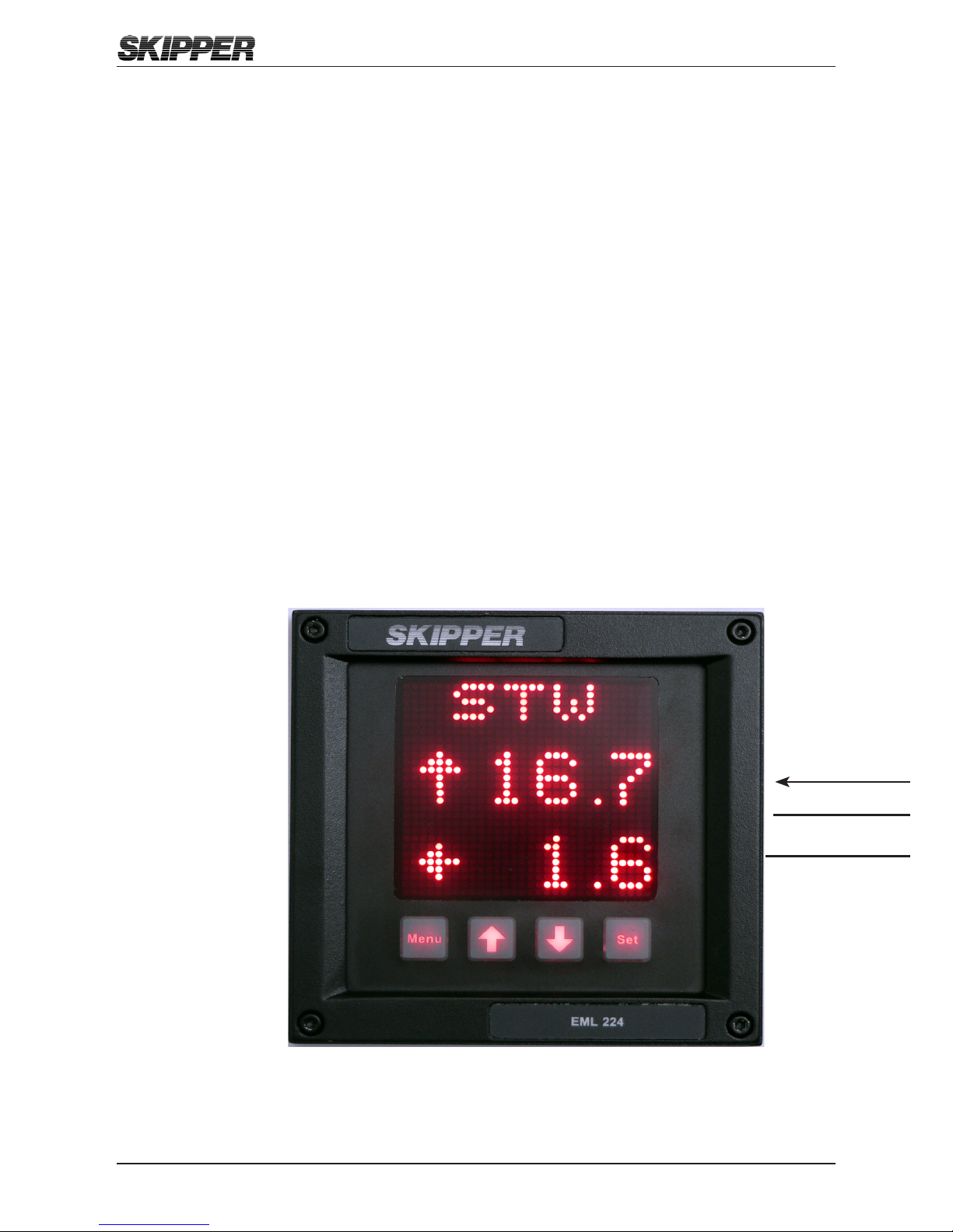
systems to be displayed anywhere on the vessel in the format the user wants.
The Compact is unique in its simple, yet exible way to display vital data in
almost all conditions, from no light to bright sunlight. In addition, it is classed to
IP56 allowing it to be mounted outside and used in any conditions. The unit is
a standard 144 mm standard format allowing it to be mounted in tight spaces
or overhead.
2 m

Operation and Installation CD401LR
Edition: 2013-11-05 Rev: 1.13 Page 11 of 28
CHAPTER 1
physiCal installation
___________________________________________________________________________
The Speed log repeater CD401LR is a stand alone unit and does not require
additional circuitry. It should be supplied by a 24 V (18 V-36 V) 25 W DC supply
and the cabling of the system is as per diagram below. The unit is supplied with
2 m of cable (12 core), this can be extended without problem. Only the wires
in use need extending.
Color
Codes
Pin no. Signals
Grey 12 NMEA2 OUT B
Turquise 11 NMEA2 OUT A
Pink 10 NMEA1 OUT B
Orange 9 NMEA1 OUT A
Violet 8 DIM DWN B
Brown 7 DIM DWN A
Black 6 DIM UP B
White 5 DIM UP A
Yellow 4 NMEA IN B
Green 3 NMEA IN A
Blue 2 0V
Red 1 +24 V
Operation and Installation CD401LR
Edition: 2013-11-05 Rev: 1.13Page 12 of 28
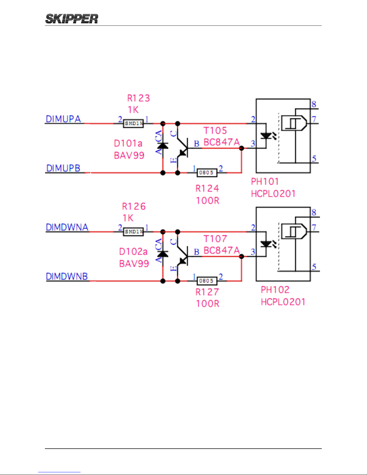
THE DIMMING INPUTS
Pulses of at least 60ms on the dimming up and dimming down cables will cause
the dimming to change by one level. The inputs are optocoupled and therefore
require an external voltage to operate, (4 Volt -30 Volt (Typically 12/24 Volt)).
Operation and Installation CD401LR
Edition: 2013-11-05 Rev: 1.13 Page 13 of 28
CHAPTER 2
setting up the CompaCt display
______________________________________________________________
PRINCIPLES
The Compact Display is a exible dot matrix LED display designed to display
navigation data. The Speed log repeater can be user programmed to show
most kinds of numerical data, from NMEA messages or self generated. It can
also be used as a primary sensor display for speed logs showing the speed
values produced by the sensor, or as a simple repeater. The Compact with its
JB60CD box meets all the requirements of a primary device both functionally
and electrically. On its own it meets the requirements as a repeater.
The Compact has three user denable alphanumeric displays, each allowing up
to 4 parameters to be displayed. When the device is used as a primary device
some of these screens will be xed.
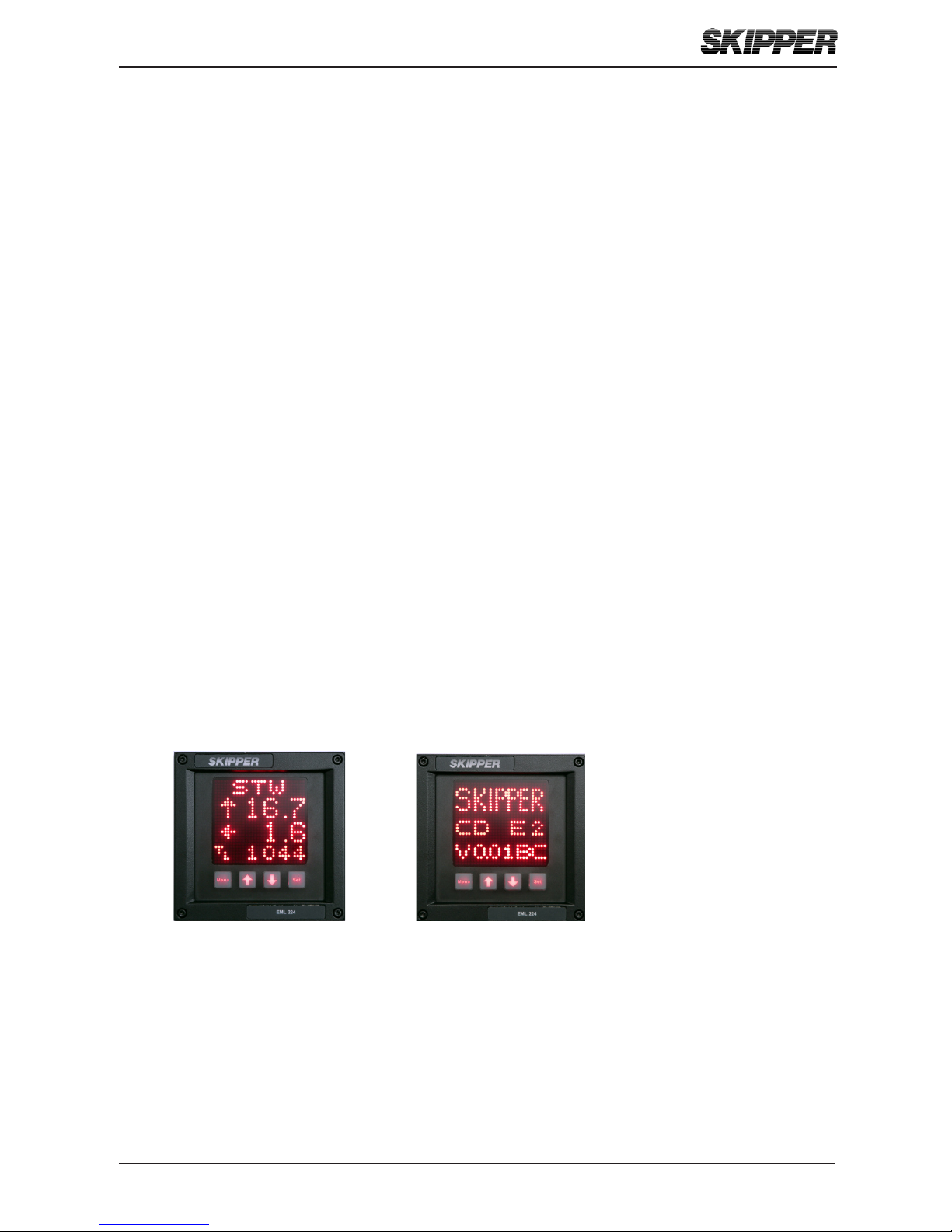
RUN SCREENS
The unit starts up in runtime mode. By pressing menu, the preset user screens
can be selected. Some of the menu screens (i.e alarms) are also available in
the runtime mode.
The unit can be dimmed in any of the runtime screens using the UP (↑) and
DOWN (↓) buttons. If Trip/Total are selected as a displayed parameter, they can
be toggled using the SET button.

Operation and Installation CD401LR
Edition: 2013-11-05 Rev: 1.13Page 14 of 28
MENU SCREENS
To change the setup of the Speead log repeater, the user must simultaneously
press MENU and SET This will give access to a menu system allowing the user
to scroll up and down the sub-menus and functions using UP (↑) and DOWN
(↓), and SET to select. To move back up a menu, the MENU button must be
pressed. The middle underlined line is the selected line. The other lines are
dimmed.
The menu structure is shown in the diagram. The menus are product dependant,
only the relevant menus are accessible. However, some menus are available
in all setups.
ACTIVATING THE RUNTIME DISPLAYS
The system has three user preset screens, Screen 1 may be locked in some
congurations. In addition the user can make the most common setup screens
available. The Screens menu allows the user to choose which runtime screens
to include. Using the SET button the user can enable, disable each individual
screen. UP (↑) and DOWN (↓) will scroll to the available screens.

Operation and Installation CD401LR
Edition: 2013-11-05 Rev: 1.13 Page 15 of 28
CONFIGURING OF DATA SCREENS
The 3 user programmable screens can be set up using
the Cong (CONFG) menu. This submenu allows the
user to select one of the three displays, and on entering
the cong screen, the user can change the data type
to be displayed in each of the 4 screen positions. Up
and down will change the data type, SET will move to
the next screen position. If text (TXT) is selected on
one of the lines, the display will show 4 lines of data
in 5 point font, otherwise 3 lines of 7 point font will be
used.
Placing TXT in the bottom 4th line or 3rd and 4th line will cause the data to spread
out showing fewer data points. The system will not allow you to mix speed data
from different sources on the same screen. Having 2 TXT lines after each other
will also rearrange the positioning.
Note: The Speed log repeater have one screen which indicates just the primary
data. This screen is xed and cannot be adjusted.
The non-active parameters will continue showing the dimmed present data,
when not selected.
Example:
TXT STW TXT STW TXT STW
STWL = 10,1 & STW L = 10,1 & STW L = 10,1
TXT STW T 0,2 STW T 0,2
TXT TXT Trip TL90683

Operation and Installation CD401LR
Edition: 2013-11-05 Rev: 1.13Page 16 of 28
Screens (SCRN)
Activate/Deactivate user denable
and runtime screens
▲ Next sub menu
▼ Prev sub menu
SET select sub menu
MENU return
System Setup (SETUP)
Setup the system parameters
▲ Next sub menu
▼ Prev sub menu
SET select sub menu
MENU return
Baud Settings (BAUD)
▲ Higher value
▼ Lower value
MENU return
Screens (SCRN)
▲ Next message
▼ Prev message
SET activate/deactivate message
MENU return
SCR1
SCR2
SCR3
INFO
menu diagram
______________________________________________________________

Operation and Installation CD401LR
Edition: 2013-11-05 Rev: 1.13 Page 17 of 28
Menus
Scrollable menu system
Accessed with SET and MENU pressed
simultainiously
▲ Next sub menu
▼ Prev sub menu
SET select sub menu
MENU return
Diagnostics Advanced Setup (DIAG)
Diagnose and adjust less used
parameters
▲ Next sub menu
▼ Prev sub menu
SET select sub menu
MENU return
Screen Conguration (CONFG)
Change the messages being
displayed on each user screen
▲ Next sub menu
▼ Prev sub menu
SET select sub menu
MENU return
Cong (CONFG)
▲ Change display message
▼ Change display message
SET move to next position on screen
Code Option activation (CODE)
Shows Serial no.
Code number with active digit
underlined
▲ Increment underlined digit
▼ Move to next digit
SET activates/deactivates the displayed
code
Upgrade mode (UPGRD)
Allow the system to upgrade from cable
Demo (DEMO)
▲ Increment mode
▼ Decrement mode
SET Accept mode
Off
Mode 1 = Dynamic
Mode 2 = Static
Splash screen (INFO)
▲ Dimming
▼ Dimming
Serial number
Option info. Software version/beta info
Self Diagnostic (TEST)
Internal test of the system.

Operation and Installation CD401LR
Edition: 2013-11-05 Rev: 1.13Page 18 of 28
ACCEPTED INPUTS
The system will allow many NMEA formats to be displayed. Version 1.02 of the
software allows the following:
Speed long, trans, fore/aft water/bottom VMVBW
Temperature (water) VMMTW,
Trip/Total VMVLW,
The system will automatically update recognized formats.
CHANGING OF THE BAUD RATE
The NMEA (IEC61162-1) standard is 4800 baud. Some vessels run with higher
baud rates. 4800, 9600, 19200, 38400, 57600 and 115200 baud rates can be
selected in the baud screen of the setup menu. It is recommended that the
sensor is kept to 4800 as this speed is robust over longer cables. The baud
rates become active as you leave the baud page.
DEMO MODE
A demo mode is available, and can be activated in the diagnostics menu. Two
modes are available.
• Mode 1 is a dynamic demo mode taking the present value as the start
point and slowly varying all the available values.
• Mode 2 is a static mode taking the present values and keeping them
active.
When the demo mode is active, alarms will be disabled, and the screen will
indicate the demo state with a solid red line at the top and bottom of the screen.
The user can turn off the demo mode from the demo screen, or by recycling the
power. The demo mode will turn off automatically after 10 hours.

Operation and Installation CD401LR
Edition: 2013-11-05 Rev: 1.13 Page 19 of 28
CHAPTER 3
routine operation
___________________________________________________________________________
RUNTIME SCREENS
The unit starts up in runtime mode. By pressing menu, the preset runtime
screens can be selected. Some of the menu screens (i.e alarms) are also
available in the runtime mode.The unit can be dimmed in any of the runtime
screens using the UP (↑) and DOWN (↓) buttons. If Trip/Total are selected as a
displayed parameter, they can be toggled using the SET button.
Operation and Installation CD401LR
Edition: 2013-11-05 Rev: 1.13Page 20 of 28
CHAPTER 4
maintenanCe
______________________________________________________________
ROUTINE MAINTENANCE
No maintenance is required. The screen can be cleaned with standard window
cleaning solutions.
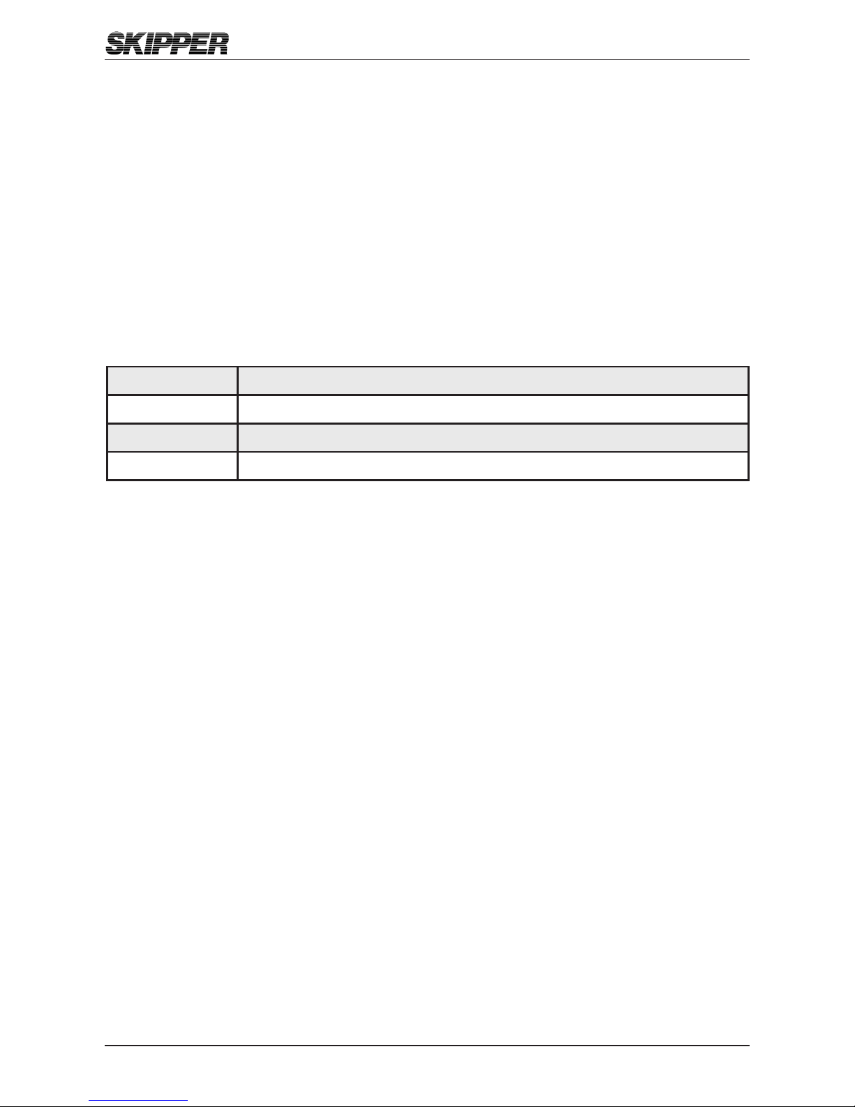
CHECKING YOUR VERSION
If the info screen is activated on the run screens, the System type and rmware
version can be read from there. Otherwise the same screen can be obtained in
the diagnostics menu. The System type will be one of the following:
CDE1 Compact display EML 1 axis
CDE2 Compact display EML 2 axis
CDLR Compact display Log Repeater
CDMR Compact display Multi Repeater
The system will be locked to one of these setups, but can be changed to one
of the other systems (with an additional cost) using a code (see appendix 4).
FIRMWARE UPGRADE
The system is undergoing continuously improvements, and periodically new
rmware will be released. A chip can be supplied (with an additional cost) with
the new software. This is changed by removing the backplate of the Speed
log repeater unit.

Operation and Installation CD401LR
Edition: 2013-11-05 Rev: 1.13 Page 21 of 28
APPENDIX 1
speCifiCation and meChaniCal drawings
______________________________________________________________
To help planning and installation, the following diagrams are supplied.
1. System full specication
2. Compact CP401 mounting diagram
In addition further guides for mounting of your particular hull mounting can be
found at www.skipper.no .

Operation and Installation CD401LR
Edition: 2013-11-05 Rev: 1.13Page 22 of 28
SYSTEM FULL SPECIFICATION
Name CD401LR-xx Speed log repeater
Accepted parameters:
Speed through water (VBW) Longitudinal, Transversal and
Transversal Aft
Speed over ground (VBW) Longitudinal, Transversal and
Transversal Aft
Water temperature (MTW)
Trip and daily total (VLW)
DISPLAY
Weight (display) 1.3 kg
Cable length display to patch 2 m, (max) 100 m
Compass safe distance (min) 30 cm
User adjustable screens 3
Parameters per display 2 with text, 3 with single text line
USER DEFINES INPUTS/OUTPUTS
Outputs 2 x NMEA (IEC61162-1) (buffered input)
Inputs 1 NMEA (OPTO isolated)
External imming (pulse)
ACCEPTED NMEA (IEC61162-1) FORMATS
Inputs
Speed VBW
Distance VLW
Others MTW (temp)
Power Supply DC: 24 V/25 Watt
Display 28 x 30 pixel alphanumeric LED (red).with
dimming.
Languages English.
Accessories Dimming control
Classication IMO MED B
Service Available in most major harbours, world-
wide through extensive dealer network. See
www.skipper.no for further information.

Operation and Installation CD401LR
Edition: 2013-11-05 Rev: 1.13 Page 23 of 28
Menu
Menu Set
1
2
3
4
144 [5,669]
Power consuption: 24 VDC/ 3W
Protection code: IP56
COMPACT DISPLAY
SKIPPER
8
.....
Set

Operation and Installation CD401LR
Edition: 2013-11-05 Rev: 1.13Page 24 of 28
APPENDIX 2
aCCepted formats
______________________________________________________________
ACCEPTED NMEA 0183 (IEC61162-1) MESSAGES
VBW Multiple
Speed
Commands
$VMVBW,x.x,y.y,A,x.
x,y.y,V,z.z,V,z.z,V
*hh<CR><LF>
Where x.x is Longitudinal
speed in knots, y.y is
transversal speed in knots,
y.y aft transversal speeds
are also accepted
VLW Distance
Travelled
through the
Water
$VMVLW,x.x,N,y.y,N
*hh<CR><LF>
x.x is Daily Trip, y.y is total
trip in NM
MTW Temperature $VMMTW,x.x,C,
*hh<CR><LF>
x.x is temperature in
Celsius
All data elds are free format. Values will be preceeded with sign as needed.
( e.g “-“ = Astern, Port) *hh = Checksum
Some proprietry sentences beginning with $PSKP can be accepted to allow
conguration and system diagnostics. Contact skipper@skipper.no for more
details

Operation and Installation CD401LR
Edition: 2013-11-05 Rev: 1.13 Page 25 of 28
APPENDIX 3
sending the system for repair
_____________________________________________________________
In the unlikely chance that a system fails, it may be necessary to send a part
of the system back for repair. Make contact with your local dealer for warranty
case (list available on www.skipper.no.)
On contact with SKIPPER, the case will be given a SKIPPERid number.
This should be quoted on all correspondace, and marked clearly on all parts
returned.
For normal service/support please contact SKIPPER Electronics AS on mail
support@skipper.no or our local dealer (list available on www.skipper.no.)
Operation and Installation CD401LR
Edition: 2013-11-05 Rev: 1.13Page 26 of 28
APPENDIX 4
other options with the CompaCt display
______________________________________________________________
COMPACT OPTIONS
The Compact display unit can be used in the following modes:
Speed repeater CD401LR
Multi repeater CD401MR
Single axis EML CD401E1 with JB60CD connection box
Dual axis EML CD401E2 with JB60CD connection box
In these modes the following options are available
Speed repeater: A simple repeater for speed in 1 or 2 axis and trip.
Limited functionality
Multi repeater: A comprehensive reopeater for many of the normal
NMEA messages, also functions for user dened
messages.
EML 224 Single
axis speed repeater.
As above but with just longitudinal value.
EML 224 Dual axis
speed repeater.
As above
The software for all these systems is stored in the system and the system
conguration can be changed using a security code. This code can be
obtained from www.skipper.no. By sending an order to SKIPPER together
with the systems serial number. (Obtained by opening the code screen in
diagnostics). On entering the supplied code number, the system options will
be set. Please note that the cabling is different for repeaters and speed logs
and so these are not compatible without replacing the back plate.
CHANGING THE SYSTEM/ ADDING OPTIONS
The Compact display unit is being developed as a low cost display alternative
to full graphics displays already available. Most extra features are available for
the Compact and these can be activated using the CODE page in the setup
menu. On this menu, the systems unique ID is displayed, and the new options
can be purchased from the SKIPPER retailer to add extra functions. You will
receive a code to be entered in the codes screen.
NOTE: It is important to note that pay option codes are unique for each
individual unit and will not work on other units.

Operation and Installation CD401LR
Edition: 2013-11-05 Rev: 1.13 Page 27 of 28

Operation and Installation CD401LR
Edition: 2013-11-05 Rev: 1.13Page 28 of 28
SKIPPER Electronics AS Telephone: +47 23 30 22 70
Enebakkveien 150 Telefax: +47 23 30 22 71
P. O. Box 151, Manglerud E-mail: support@skipper.no
0612 Oslo, Norway Co. reg. no: NO-965378847-MVA
www.skipper.no
 Loading...