


REVISED 16. JUNE. 2017
SKIPIO
Commercial Refrigerators & Freezers
User Manual
REACH-IN (UPRIGHT)
SRT, SFT & SRFT series
Chiller, Freezer & Dual Temperature

Turbo Air Warranty
WARRANTY CLAIMS – The user must report to its dealership, hence the dealer
can accumulate all pertinent information supporting the existence of the alleged
defect.
TWO YEARS PARTS & LABOUR WARRANTY
Turbo Air warrants to the original purchaser of every new Turbo Air refrigerated unit, the cabinet
and all parts thereof, to be free from defects in material or workmanship, under normal use and
service, for a period of two (2) year from the date of original installation.
Any parts covered by this warranty that are examined and determined by Turbo Air to have been
defective within two (2) year of original installation shall be repaired or replaced as stated below.
Turbo Air shall be deemed to have full complied with its obligation under the foregoing warranties
by electing either one of the following procedures, at the sole discretion of Turbo Air:
(a) Furnishing a replacement part, freight collect, in even exchange for the returned part,
freight collect;
(b) Receiving the defective part, freight collect; repairing it, freight collect.
What is NOT covered by this warranty?
Turbo Air’s sole obligation under this warranty is limited to either repair or replacement of parts,
subject to the additional limitations below. This warranty neither assumes nor authorizes any
person to assume obligations other than expressly covered by this warranty.
1. Warranty is NOT TRANSFERABLE. This warranty is not assignable and applies only in
favour of the original purchaser/user to whom delivered. ANY SUCH ASSIGNMENT OR
TRANSFER SHALL VOID THE WARRANTIES HEREIN MADE AND SHALL VOID ALL
WARRANTIES, EXPRESS OR IMPLIED, INCLUDING ANY WARRANTY OF
MERCHANTABILITY OR FITNESS FOR A PARTICULAR PURPOSE.

REVISED 16. JUNE. 2017
2. NO CONSEQUENTIAL DAMAGES, TURBO AIR IS NOT RESPONSIBLE FOR
ECONOMIC LOSS; PROFIT LOSS OR SPECIAL, INDIRECT, OR CONSEQUENTIAL
DAMAGES, INCLUDING WITHOUT LIMITATION, LOSSES OR DAMAGES ARISING
FROM FOOD OR PRODUCT SPOILAGE CLAIMS WHETHER OR NOT ON ACCOUNT
OF REFRIGERATION FAILURE.
3. ALTERATION, NEGLECT, ABUSE, MISUSE, ACCIDENT, DAMAGE DURING TRANSIT
OR INSTALLATION, FIRE, FLOOD, ACTS OF GOD, TURBO AIR is not responsible for
the repair or replacement of any parts that Turbo Air determines have been subjected after
the date of manufacture to alteration, neglect, abuse, misuse, accident, damage during
transit or installation, fire, flood, or an Act of God.
4. TRANSPORTANTION COSTS – Turbo Air will accept parts covered under this warranty
freight collect, provided that shipment has received prior approval. Turbo Air is not
responsible for any other transportation costs, but will ship freight collect parts either
repaired or replaced under this warranty.
5. Any services from an unauthorized person including owner – Turbo Air will not accept
misuse of display controller which is not mentioned on user manual.
6. Warranty does not cover any services from any unauthorized technician including owner.
7. Consumable parts such as door gaskets, castors, legs, etc. are excluded from the
warranty.

REVISED 16. JUNE. 2017
Contents
1. MODELS ........................................................................ 5
2. INSTALLATION ............................................................. 6
Warning & Safety Instructions ................................................................................................. 6
Installing the Unit ........................................................................................................................... 7
1. Avoid heat source ....................................................................................................................... 7
2. Levelling ......................................................................................................................................... 7
3. Ventilation ...................................................................................................................................... 8
Shelving ................................................................................................................................................ 8
Loading Product ............................................................................................................................... 9
3. OPERATION ......................................................................................................................... 10
Start Up .............................................................................................................................................. 10
Electronic Controller ................................................................................................................... 10
Power On/Off .................................................................................................................................... 11
Lock/Unlock the display controller ...................................................................................... 11
Controller Alarms for users ...................................................................................................... 12
4. SERVICING ........................................................................................................................... 13
Cleaning Cabinet ........................................................................................................................... 13
Cleaning Condenser ..................................................................................................................... 13
Troubleshooting ............................................................................................................................. 14

Model
Type
Config.
Doors
Operating temperature range
SRT25-1
Refrigerator
Solid Door
1
+1°C to +8°C up to 38°C ambient
SRT25-2
Refrigerator
Solid Door
2
SRT45-2
Refrigerator
Solid Door
2
SRT45-4
Refrigerator
Solid Door
4
SRT65-3
Refrigerator
Solid Door
3
SRT65-6
Refrigerator
Solid Door
6
SFT25-1
Freezer
Solid Door
1
-21°C to -12°C up to 38°C ambient
SFT25-2
Freezer
Solid Door
2
SFT45-2
Freezer
Solid Door
2
SFT45-4
Freezer
Solid Door
4
SFT65-3
Freezer
Solid Door
3
SFT65-6
Freezer
Solid Door
6
Model
Type
Config.
Doors
Operating temperature range
SRFT25-2
Dual Temp
Solid Door
2
R-Compartment
+1°C to +8°C up to 38°C ambient
F-Compartment
-21°C to -12°C up to 38°C ambient
SRFT45-2
Dual Temp
Solid Door
2
SRFT45-4
Dual Temp
Solid Door
4
SRFT65-3
Dual Temp
Solid Door
3
SRFT65-6
Dual Temp
Solid Door
6
Model
Type
Config.
Doors
Operating temperature range
SRT25-1G
Refrigerator
Glass Door
1
+1°C to +8°C up to 38°C ambient
SRT45-2G
Refrigerator
Glass Door
2
SRT65-3G
Refrigerator
Glass Door
3
SRT25-2G
Refrigerator
Glass Door
2
SRT45-4G
Refrigerator
Glass Door
4
SRT65-6G
Refrigerator
Glass Door
6
SFT25-1G
Freezer
Glass Door
1
-21°C to -12°C up to 38°C ambient
SFT25-2G
Freezer
Glass Door
2
SFT45-2G
Freezer
Glass Door
2
SFT45-4G
Freezer
Glass Door
4
SFT65-3G
Freezer
Glass Door
3
1.MODELS
UPRIGHT SOLID DOOR
REVISED 16. JUNE. 2017
UPRIGHT SOLID DOOR – Dual Temperature
UPRIGHT GLASS DOOR

REVISED 16. JUNE. 2017
2. INSTALLATION
Warning & Safety Instructions
This appliance conforms to current safety requirements. However, inappropriate use can cause
injury and damage to property.
Do not cover the grilles or block the entry of airflow (condenser) or exhaust of airflow by
placing objects up against the refrigeration unit;
Ensure adequate ventilation provided for the appliance as this is essential to
performance, at least 50 mm from the wall;
Ensure the safe power supply and current draw for the appliance as overload of the
power supply can damage the entire unit;
Ensure to install the appliance indoor;
Avoid damp and dusty environment which may cause electric shock;
Use casters or legs for the unit;
Must disconnect the unit from the power supply prior to cleaning or maintenance;
Ensure not to put hot food in the unit;
Preferred to use the leakage protector to prevent the short circuit;
Ensure not to store volatiles and combustibles inside cabinet.

REVISED 16. JUNE. 2017
Installing the Unit
1. Avoid heat source
Avoid direct sunlight, uneven surface, hot environment beyond recommended ambient
temperature of the cabinet.
The unit must NOT be situated where it is affected by hot air from adjacent equipment as this will
compromise the airflow and performance of the cabinet.
2. Levelling
If the cabinet is installed on an even surface or not levelled, water from condensate tray may
overflow.
Once, water leakage occurs by inappropriate levelling, the unit has to be re-levelled. Turbo Air is
not obligated to provide warranty service in case of operator error.
A spanner and four spacers are included in a package. A scissor jack (car jack) is required to lift
up the cabinet for easy placement of the spacers.
Loosen the screw to provide enough gap for spacers and fasten it.
REVISED 16. JUNE. 2017
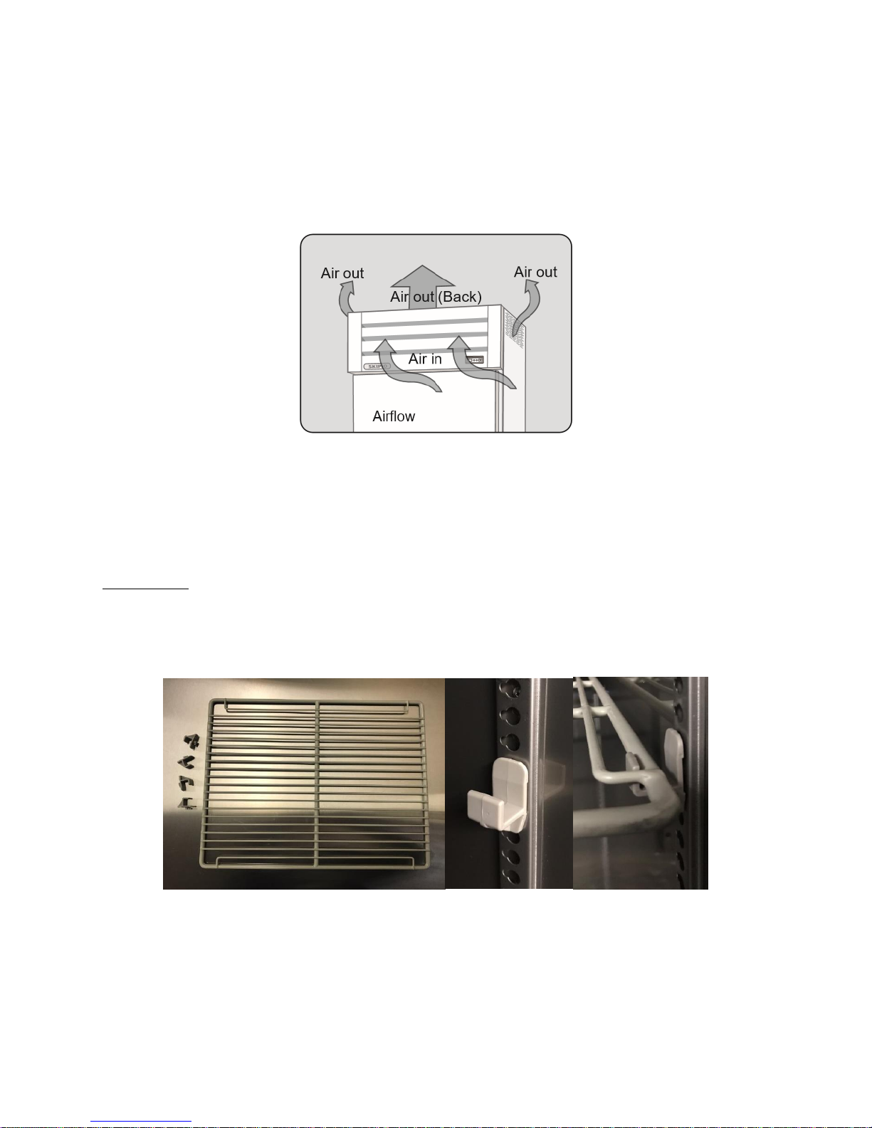
3. Ventilation
Providing an environment with good ventilation prolongs the life of compressor and performance.
Air flows into condenser (front) and the outflow of the used air is exhausted via outlets. For efficient
operation of the cabinet, providing adequate ventilation and ambient temperature (below 38°) is
essential.
Prior to installation of the unit, a gap of at least 50 mm must be left from the walls as outlets of
the used air are located at the back of the unit.
Shelving
Inside the cabinet, there is a shelf package. Remove all packaging material. Each shelf is paired
with 4 support brackets (shelf clips).
The shelves can be positioned at different heights for customer’s preference. Always ensure that
the support brackets are securely engaged in each of the shelf support rail.
It is recommended that the cabinet operates for 30 minutes prior to loading product.

REVISED 16. JUNE. 2017
Loading Product
Do not overload products: a maximum loading of 20kg per shelf
Do not allow products to overhang the front of the shelf which may prevent the door from
shutting
Place products with air space for even cooling and efficient operation

REVISED 16. JUNE. 2017
3.OPERATION
Start Up
Plug into the main power supply and check operation of the unit, front display and lighting. The
compressor and the condenser and evaporator fans should all operate within 2 minutes from the
moment the unit is plugged in. The cabinet light (inside) will go on when a door is opened.
Electronic Controller
Turbo Air electronic controller controls and displays the internal cabinet temperature. For general
operation, no initial setup or additional programing is required. When the cabinet is connected to
the power supply, the current cabinet temperature will be displayed on the electronic controller.
Generally, the compressor and evaporator fan will operate within 2 minutes after power supply to
the cabinet.
1. Electronic controller for freezers (SRT/SFT-series)
Factory setup temperature of SFT-series is - 18°C. By pressing either up or down button, setting
temperature can be adjusted according to customer’s preference.
Factory setup temperature of SRT-series is 2°C. By pressing either up or down button, setting
temperature can be adjusted according to customer’s preference.

REVISED 16. JUNE. 2017
Power On/Off
Plugging into the power automatically turns on the cabinet. There are several ways manually
power on and off while pugging in.
1. There is a power switch located at the top of the cabinet (near condenser).
2. Alternatively, the cabinet can be turned on and off by pressing down button on the front
display for 10 seconds.
Lock/Unlock the display controller
To prevent anyone adjusting setting, press up button for 10 seconds, which will lock the display
controller.
Pressing up button for 10 seconds will unlock the display controller.

REVISED 16. JUNE. 2017
Controller Alarms for users
Electric controller When the inside temperature is lower than - 45°C, the panel will display ‘LO’,
and higher than +18°C, ‘HI’ will be displayed.
Defrost starts when the icing on the evaporator occurs: usually 4 ~ 6 times a day.
It will take 20 ~ 30 minutes to finish defrost. The compressor drops the cabinet temperature down
to further – 7°C on the current setting temperature.

REVISED 16. JUNE. 2017
4.SERVICING
Cleaning Cabinet
Using a damp cloth for cleaning both the interior and exterior of the cabinet is recommended when
it requires. Before cleaning, the cabinet should be disconnected from the power supply.
Cleaning Condenser
Cleaning condenser coils is the most important thing a customer’s can do to maintain a
freezer/refrigerator’s longevity. The condenser coil is located behind the top grile. The condenser
coil must be maintained clean for reliable and efficient operation. Condenser blockage may cause
shortening the life of the compressor and, increasing power consumption.
To ensure trouble free performance, the condenser coil should be brushed once a month.
Easy access to the condenser from the top will allow simple and quick cleaning environment.
As shown the picture above, condenser is located at the top of the unit. A ladder is required to
access to the top of the unit. On the top of the unit there is a cover which can be removed by a

REVISED 16. JUNE. 2017
Issue
Possible cause
Resolution
Warm cabinet temperature
Condenser blockage
Poor ventilation environment
Clean condenser
Provide good ventilation around the side
and back of the unit
Power consumption is higher
than supposed to be
Dirty Condenser
Unit operating in too high temperature
Cabinet doors are opened excessively
Clean condenser
Provide good ventilation around the side
and back of the unit
Keep door/s open for minimum time
Water leakage inside cabinet
Unit is not levelled properly
Level the unit
(Ref: 2 Installation – Levelling)
No power to unit
Unplugged
Accidently turned off via display
(Ref: 3 Operation – Power On/Off)
Power switch off in the condensing unit
(Ref: 3 Operation – Power On/Off)
Plug in
Press down button for 10 seconds
(Ref: 3 Operation – Power On/Off)
Power switch on in the condensing unit
(Ref: 3 Operation – Power On/Off)
Display controller does not
work
Locked (Ref: 3 Operation – Lock/Unlock
the Display Controller)
Press up button for 10 seconds
(Ref: 3 Operation – Lock/Unlock the Display
Controller)
screw driver or a hand drill. Once, open up the top cover, brush the condenser and reassemble
the cover.
Over time, dust may accumulate within the condenser that cannot be removed with a brush. If
this occurs, contact Turbo Air to arrange for a Turbo Air authorized service agent to clean the
condenser with compressed air.
Troubleshooting
 Loading...