

Page 1
USER MANUAL FOR
DIGR-1502/E CONTROLLER
Version: 1.3
October 2018
Page 2

CONTENTS
1. Technical data.................................... 3
2. Description ...................................... 3
3. Connection ....................................... 7
4. Operating status ................................. 11
5. Activation ....................................... 11
6. R-run / S-stop ................................... 12
7. Setting and saving parameters .................... 12
8. Description of parameters ........................ 12
9. Maintenance ...................................... 22
10. Disposal ...................................... 22
11. Guarantee ..................................... 22
12. ES Declaration of conformity .................. 23
2/23
Page 3

1. Technical data
Power supply voltage U
110-230V 50/60Hz
nap
Power input current 4.5 A
Output voltage 5-100% U
with 0.5% steps
nap
Output frequency 20-120 Hz with 0.2 Hz steps
2x digital input 24V DC PNP
2x digital output 24V DC max. 120 mA
1x analogue input 0-10V DC
Auxiliary output voltage 24V DC max. 180 mA
10V DC max. 10 mA
Interference suppression class A according
to ČSN EN 55011 ed.4
Overvoltage category II according
to ČSN EN 61010-1 ed.2
Short circuit resistance 450 A
Internal fuse value T8A
Protection level IP54
Operational temperature 10-40ºC
Altitude max. 2000 m
Dissipated power 10 W
Weight 1.3 kg
2. Description
The DIGR-1502/E controller is designed for control of
vibration feeders driven with an electromagnetic coil.
Two basic parameters, i.e. output voltage amplitude and
frequency are controlled. The operation of the
controller is defined with parameters that are set by
the user from the control panel. Control of the
controller is possible either from the control panel or
using external analogue and digital signals.
The controller is designated for installation outside
of the switchboard. The controller includes also
a safely separated 24V DC power supply for feeding
peripheral devices such as sensors, air valves, and for
10V DC power supply for analogue input feeding.
Small size and effective user functions create
prerequisites for deployment of these controllers
operating both independently and together with a master
control system in most feeder applications.
3/23
Page 4
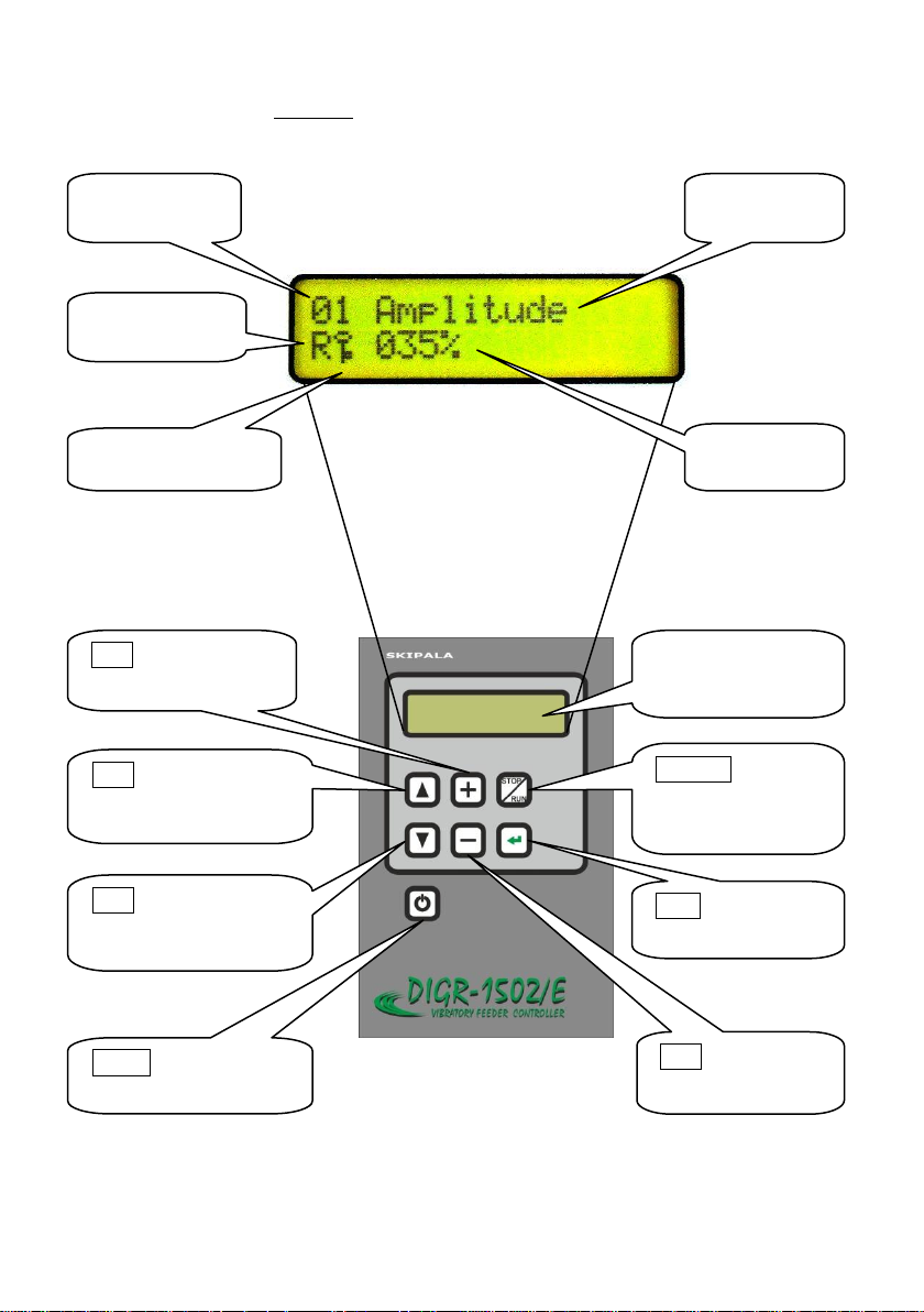
Fig. 1 – Description of controls
Display
2 x 16
characters
stop
/
run
–
Switching over
in S-stop or
R-run condition
enter
- Saving
the set values
+ - Increase
displayed value
- - Decrease
displayed value
▲ - Browsing
through parameters
upward
▼ - Browsing
through parameters
downward
on
/
off
- Controller
turning on/off
Parameter
number
Operational
status
Parameter
value
Parameter
name
Parameter
locked/unlocked
4/23
Page 5
66,00
120,00
130,00
28,50
167,00
192,00
6,50
110,00
105,00
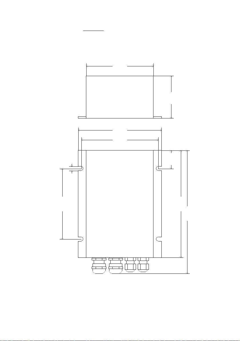
Fig. 2 – Basic dimensions
5/23
Page 6
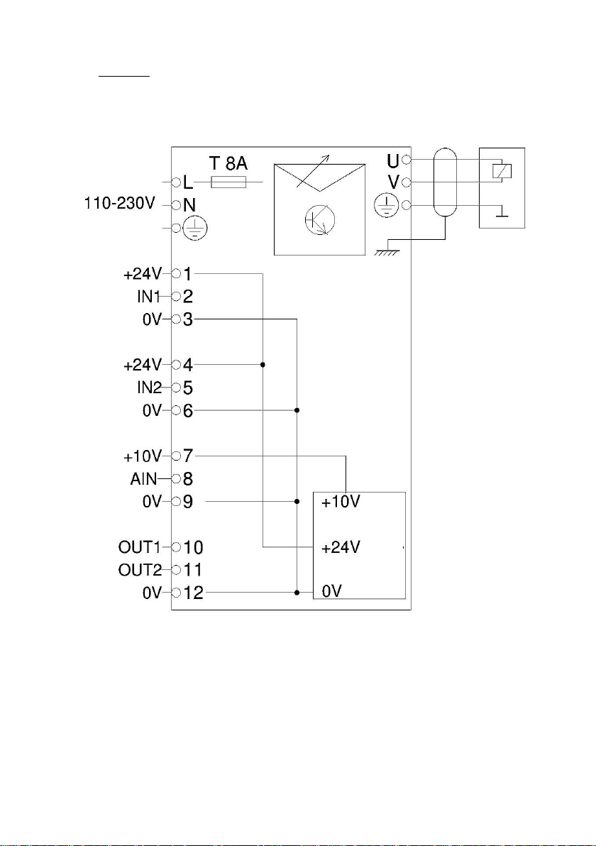
Fig. 3 - Connection of controller external parts
supply
drive
internal
source
6/23
Page 7
3. Connection
Connection of external electric components of the
controller may be carried out only by the person with
adequate electro-technical qualification. Connection
may be done only if the controller is disconnected from
the mains.
Caution! Electric charge remains in capacitors
after controller disconnection from the mains. This
electric charge may become a cause of fatal injury! The
lid may be removed only if the controlled has been
disconnected from the mains for at least 60 seconds!
Caution! If the device is used in a manner not
specified by the manufacturer, the protection provided
by the device may be compromised!
3.1. Installation
The controller can be installed either in the
horizontal position or in the vertical position with
outlets facing downward.
Caution! The controller should be mounted to
a mechanically stable part of equipment free of direct
vibrations.
Drill four holes with a drill with diameter of 4.2 mm
in the base plate to which the controller should be
mounted and cut M5 threads in them. The pitch of the
holes is apparent from Fig. 2. Mount the controller
using 4 M5x8 screws with fan washers.
Caution! Washers are needed so when tightened
the layer of elox is cut and the controller is
conductively joined to the body of the machine.
3.2. Lid disassembly
Unscrew four M3 screws mounting the controller lid
and remove the lid (Fig. 4).
7/23
Page 8
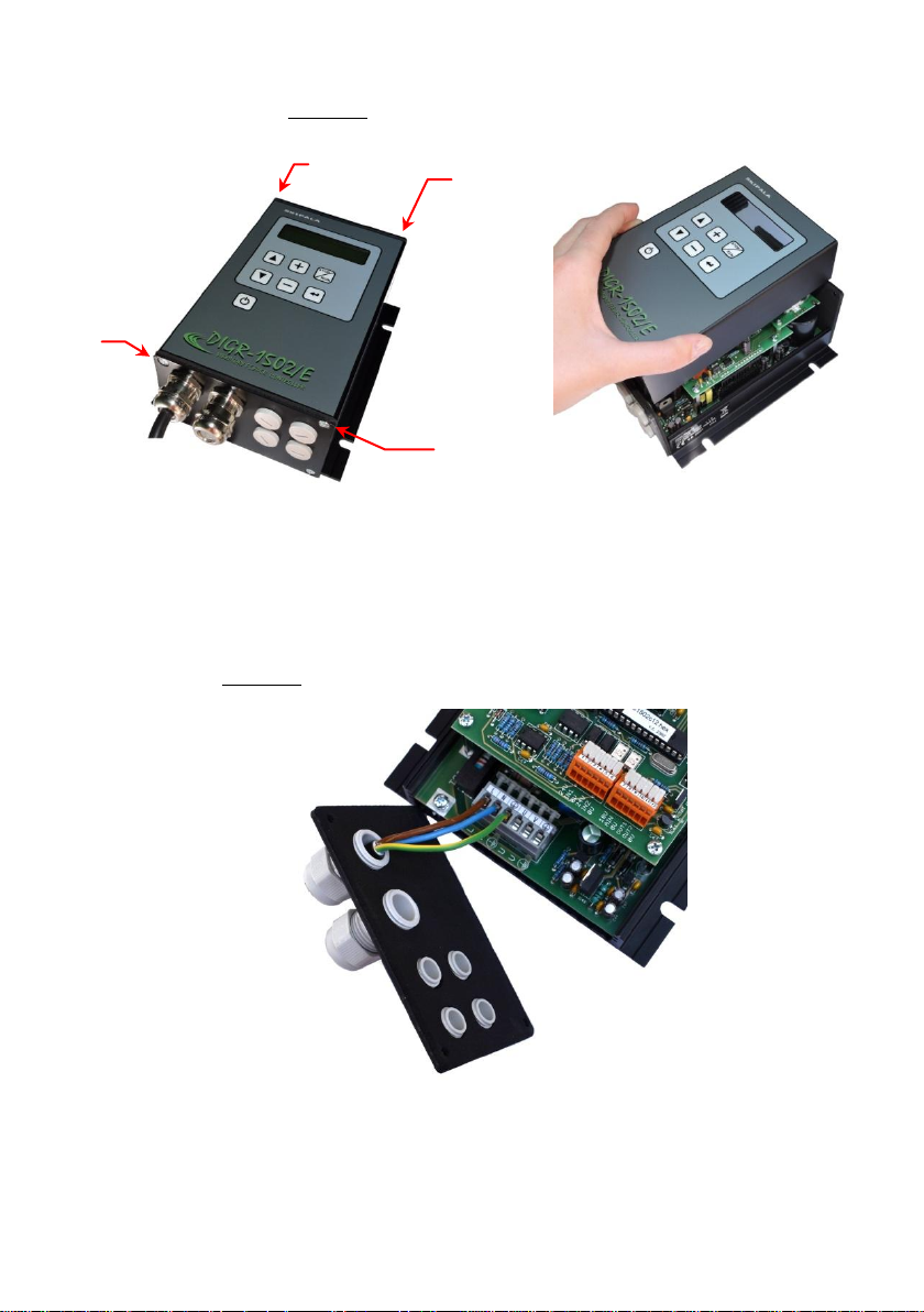
Fig. 4 – dismantling of the cap
M3
M3
M3
M3
To allow better access to the terminal block, we
recommend dismounting also the part with outlets
(Fig. 5).
Fig. 5 – Removal of the part with outlets
There are connecting terminals under this lid
(Fig. 6).
8/23
Page 9
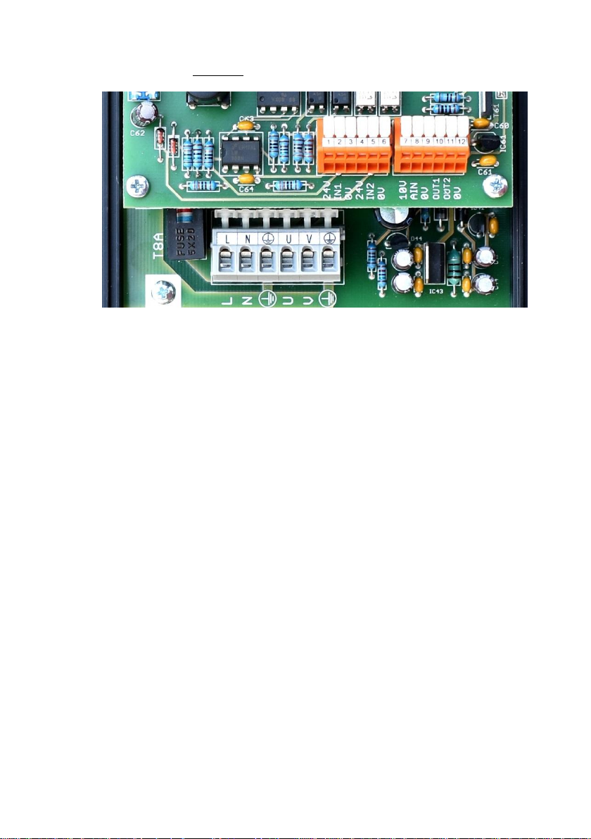
Fig. 6 – Connecting terminals
3.3. Connection of the power section
The controller is equipped with a 2P + PE terminated
lead cable. Connect the plug to a standard 230V socket
that is triggered by a circuit breaker with a maximum
rated current of 16A characteristic B. The fork acts as
a disconnect device and must be placed in a convenient,
easily accessible position near the controller.
If the controller is incorporated into the wiring of
a superior unit such as a machine, the connection is
made by a flexible cable of 3x 1.5 mm2 which is
triggered by a circuit breaker with a maximum rated
current of 16A characteristic B. This installation must
be equipped with a disconnecting device that
disconnects all conducting currents.
Connect the feeder coil to the PE, U, V terminals
(Fig. 8). We recommend using a shielded cable. If more
controllers are connected to the equipment, it is
necessary to connect them to different phase wires or
ensure their sequential switching on, because of the
current peak.
Termination of the power cables is illustrated in
Fig. 7. Select the wire section areas as follows:
Wire cross section area 0.75 – 1.5 mm2
Cable diameter 8 - 10 mm
9/23
Page 10
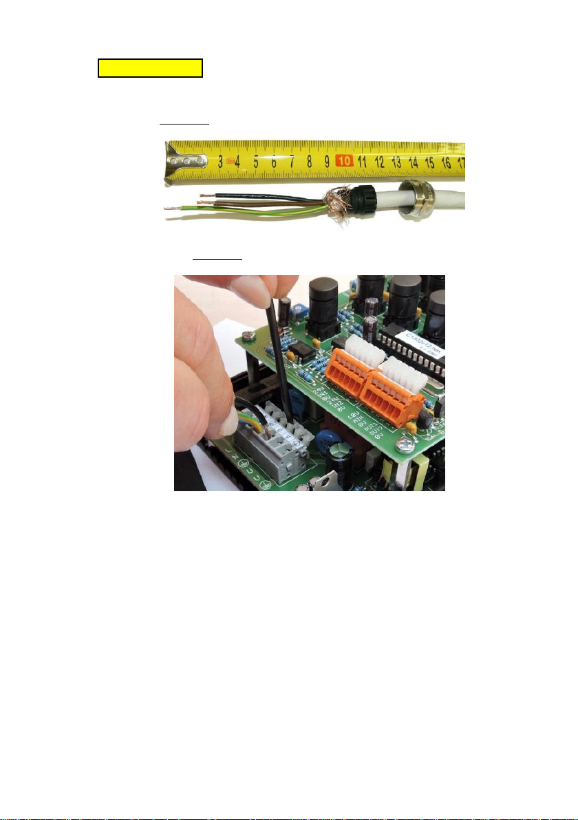
Caution! The protective wire should be at least
by 15 mm longer than the other wires.
Fig. 7 - Termination of power cables
Fig. 8 – Connection of wires
3.4. Connection of the control section
Wire cross section area 0.08 – 0.5 mm2
Cable diameter 3 - 6.5 mm
Connect the sensors, valves, digital and analogue
signals as required by a specific application, in
accordance with Fig. 3. Detailed explanation - please
see Section 8.7.. The inputs and outputs are fed with
safely separated voltage of 24V DC. Use PNP sensors
(the output signal is switched to +24V).
3.5. Lid reassembly
After completing connection of the external parts of
the controller, carry out reassembly of the part with
grommets and top lid. Only then you can turn power
supply on.
10/23
Page 11
4. Operational condition
Operational condition is shown on the display as the
first symbol of the bottom line (Fig. 1). The controller
can be in one of four statuses:
The controller is energized, however, all activities
are turned off.
S STOP - The controller is turned on and it is in the
S-stop condition. Output power voltage is blocked,
the feeder is idle. Viewing and modifications of all
parameters and saving the parameters in the memory
is possible.
R RUN (operation)- The controller is turned on and it
is in the R-run condition. Output voltage is
connected and the feeder is vibrating. Viewing and
modifications of all parameters are possible.
W WAIT - The controller is turned on and it is in the
W-wait condition. Output power voltage is blocked,
the feeder is idle. The controller waits for
a signal from sensors or from a master control
system. Viewing and modifications of all parameters
are possible.
5. Turning ON
Controller turning on can be carried out using two
methods:
a) Turning on is to be carried out by depressing the
button on/
. Turning off can be carried out by
off
depressing the button again.
This method of turning on is suitable in case that
the controller operates independently without link
to any other electric equipment.
Caution! Internal circuits of the controller
are still energized and for that reason, such
turning off cannot be considered as safe
disconnection from the mains! This condition is
indicated on the display with the symbol .
b) Turning on is carried out automatically after power
supply voltage connection. For this purpose, it is
necessary to set the parameter A36 to “automatic”.
This method of turning on is suitable if controller
power supply is connected through a connecting
11/23
Page 12

component (contactor) from a master electric
device.
6. R-run / S-stop
The controller is ready for operation after turning
on. It is either in the R-run or W-wait condition in
dependence upon setting of functions of digital inputs
(parameter A19, A21). The controller is switched over in
the S-stop condition after depressing the
stop
/
button.
run
When depressing the button again, the controller will be
switched from the S-stop in R-run or W-wait condition.
7. Setting and saving of parameters
Select the required parameter using the ▼ and ▲
buttons. If it has not been locked (key symbol), the
value of parameter can be modified using the + or –
keys. Press the
enter
button to save, all parameters are
saved in the memory at once. It is recommended to save
in the S-stop status.
First, locked parameters must be unlocked by typing
the password, parameter A41 (Chapter 8.28.).
8. Description of parameters
The controller contains a set of parameters marked
A10 - A41. Parameter numbers do not form a continuous
series of numbers for compatibility with other
controllers.
8.1. A10 Amplitude
The controller controls output voltage amplitude
within the maximum range of 5-100% with 0.5% steps. The
effective value of voltage depends on power supply
voltage. Range of setting is restricted with the value
of the parameter A17 Maximum amplitude and A18 Minimum
amplitude.
8.2. A11 Frequency
The controller controls output voltage frequency
within the range of 20-120 Hz with 0.2 Hz steps.
8.3. A12 Delay ON
A13 Delay OFF
The parameters sense if at least one senor is
connected to the controller monitoring the filling of
12/23
Page 13

the output storage tank of the feeder. We recommend
setting parameters to 0 s.
If the controller is in the W-wait status parts are
taken from the storage and their movement causes
a short interruption of the signal from the filling
sensor. The Delay ON (parameter A12) must be longer
than the interruption of the signal. Then the
interruption will be ignored and the controller
switches into the R-run status after the storage tank
is discharged. The same occurs after the storage tank
is filled. Individual parts pass around the sensor and
create short impulses. The Delay OFF (parameter A13)
must be longer than these impulses. Then they will be
ignored and the controller switches into the W-wait
status after the actual filling of the magazine. The
parameters can be set from 0-25 s.
8.4. A14 Ramp up/down
This parameter can be used when starting and running
down the feeder to change the value of the amplitude so
that the feeder starts to run fluently. The setting
range is 0-6 s. The time relates to starting from 0% to
100% and running down from 100% to 0%.
8.5. A15 Batch ON
A16 Batch pause
In some cases, the feeder needs to work with
interruptions, in batches. Use parameter A15 to set the
time during which the batch is supplied, parameter A16
the time of the pause between batches.
Tip for you: The vibrating feeder serves as
a pre-storage tank that delivers the parts to the
circular feeder on the basis of the full sensor signal.
If you take advantage of the batch function, the
pre-storage tank fulls only one batch, waits, then
evaluates the status of the full sensor and, if
necessary, gives a next batch. Parts of the hopper will
spread evenly during the pause. This ensures that the
hopper does not overfull.
8.6. A17 Amplitude Maximum limit
A18 Amplitude Minimum limit
Use these parameters to restrict the amplitude
setting in parameter A11.
13/23
Page 14

Tip for you: The operators can correct the value
within the permitted range without greatly affecting
the correct work of the feeder.
8.7. A19 Input IN1
Determining the use of digital input IN1.
Not used – The input is not used or is only monitored
and its state is transferred to the output
(Chapter 8.12).
Start – The +24V signal must be supplied so that the
feeder can be activated. If the remaining
conditions are fulfilled as well (according to
the configuration for additional inputs), then
upon supply of the 24V signal the feeder will be
in the R-run status. Otherwise, the feeder is in
the W-wait status. Switching from the W to R
status and vice versa is immediate, the
parameters A12, A13 do not affect this.
Tip for you: Use this setting if the feeder
is controlled from a master control system.
Maximum stock - The sensor is connected to the input
monitoring the maximum stock in the storage tank
being filled by the feeder. If the sensor is
active during the period stated by the parameter
A13, the feeder is stopped and switched to the
W-wait status. Returning to the R-run status
depends on whether the second input is defined as
the minimum stock. If so, the feeder is activated
according to the status of this sensor (see
below). The feeder is switched to the R-run
status after the maximum stock sensor is not
active for the time stated by the parameter A12.
Tip for you: By setting parameters A12, A13
properly only one sensor is sufficient for
monitoring the storage tank.
Minimum stock – This setting is only used if the
second output is defined as the maximum stock.
The sensor monitoring the minimum in the storage
tank is connected to the input being filled by
the feeder. The feeder is switched to the R-run
status after the minimum stock sensor is not
active for the time stated in parameter A12. If
14/23
Page 15

both stock sensors are active for the time in
parameter A13 activity stops.
Ejector IN – The input controls the ejector together
with the digital output OUT1, OUT2 (Chapter
8.12.).
8.8. A20 Sensor 1 type
Type of sensor connected to input IN1.
Normal open (NO) - 24V is on the output of the
sensor if the supplied part is present.
Normal close (NC) - 24V is on the output of the
sensor if the supplied part is not present.
8.9. A21 Input IN2
Determining the use of digital input IN2. The setting
is identical as for input IN1 (Chapter 8.7.).
8.10. A22 Sensor 2 type
Determining the type of the sensor connected to
input IN2. The setting is identical as for input IN1
(Chapter 8.8.).
8.11. A23 Analogue AIN
Determining the use of analogue input AIN. It can be
configured as analogue 0-10V, or digital 0/24V.
Not used - The input is not used.
Amplitude - The input is configured as analogue. The
0-10V voltage is used to set the amplitude and
intensity of vibrations of the feeder from 5-100%
with 0.5% steps. The setting range can be
restricted by parameters A17, A18. The set value
is displayed in parameter A11.
JOG-min – The input is configured as digital. 24V
signal on the input causes the amplitude to
switch to the minimum value, which is determined
by parameter A18. Tip for you: Use this
setting if you need to decrease the speed of the
feeder during the activity. For example, when
pouring material on the scale when approaching
the desired weight.
Start – The input is configured as digital. The
supply of the +24V signal is the condition for
15/23
Page 16
the feeder to be activated. Tip for you: Use
OUT
IN2
LE V E L
T IME
A16A15
LEVEL
TIME
IN2
OUT
Par.A25
T1
Par.A26
T2
this setting if you need to control the feeder
from the master control system and digital inputs
IN1, IN2 are occupied by the connected sensors.
Stop – The input is configured as digital. The supply
of the +24V signal causes the controller to stop.
8.12. A24 Output OUT1
Determining the use of digital output OUT1.
Tip for you: A pneumatic valve which controls
the air jets, switches or ejectors, for example, can be
connected to the digital output. The master control
system PLC or signaling beacon can be used as the
signal, or as the signal if the controllers are
connected in a cascade.
Not used - The input is not used.
Run status – Output is always switched when the drive
is in the R-run status.
Air jet – The output controls the air supply valve
into the feeder. The valve is switched on before
activation of the feeder. The time is set using
parameter A25 (Timer T11). When the feeder is
turned off, the air is turned off with a delay,
which is set using parameter A26 (Timer T12).
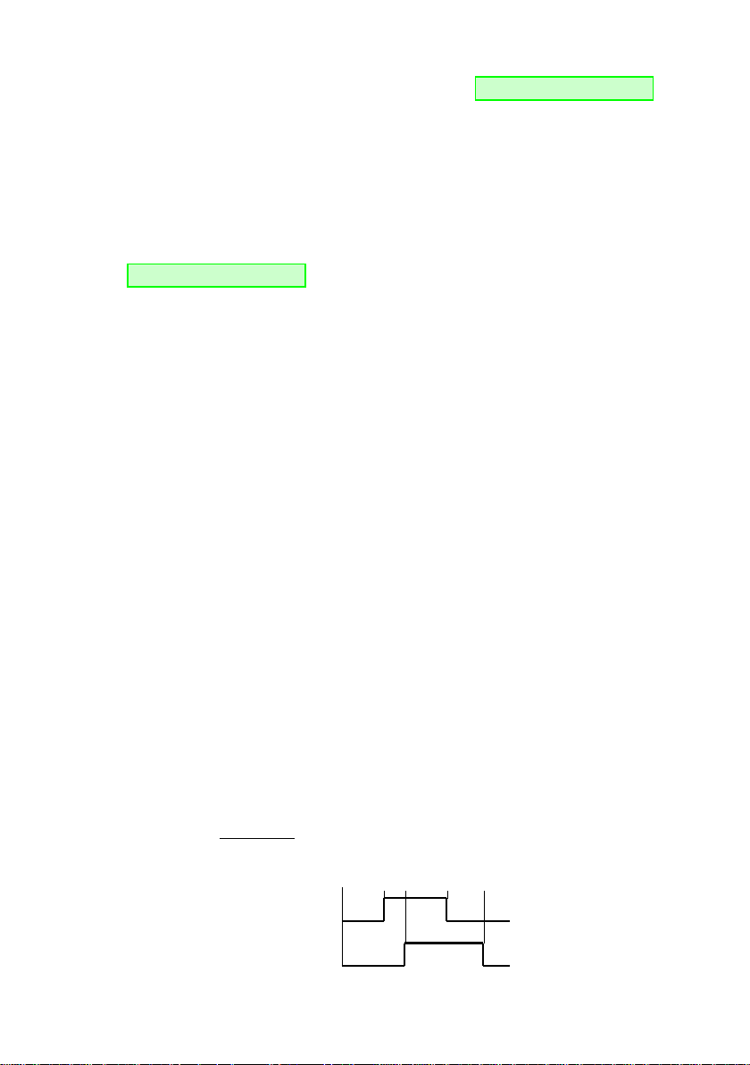
Ejector E1 (Fig. 9a) – The output is connected to the
valve controlling the ejector i.e. equipment
removing incorrectly oriented or redundant parts
from the route of the feeder. One of the inputs,
e.g. IN2, must be set to the ejector function
(Chapter 8.9.). The sensor is connected to the
input reading the parts. Use Timer T11 (parameter
A25) batch ON to set the delay so that the
ejector does not respond to short impulses from
the sensor. Use Timer T12 (parameter A26) batch
OFF to change the ejection time.
Fig. 9a – activity of the ejector E1
16/23
Page 17
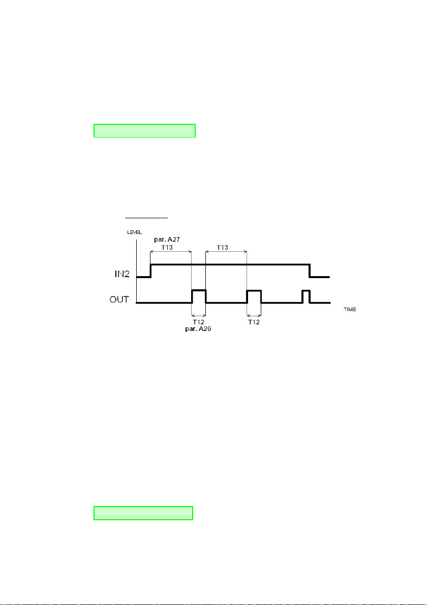
Ejector E2 (Fig. 9b) – is similar to the ejector E1,
except that it uses three timers. Timer T11
(parameter A25) suppresses short impulses at the
input IN2. Timer T13 (parameter A27) determines
the delay between the signal IN2 and switching
output OUT. Timer T12 (parameter A26) determines
the length of switching output OUT.
Tip for you: Ejector E2 is good for example
for detecting the stuck parts. If parts are not
passing under the sensor for time T13 (parameter
A27) the output OUT is switched, which is
connected to the valve that controls air nozzles,
which blow off stuck parts from the feeder track.
Fig. 9b – activity of the ejector E2
Monitor IN1 ON – The output monitors the activated
status of digital input IN1. This is only
monitored when the drive is in the status RUN operating. If during the period set by parameter
A27 (Timer T13), there is signal 24V on input
IN1, the output OUT switches on. The signal on
the monitored input can be protected from short
impulses, which are caused by the movement of
parts under the sensor. Impulses from status 0 to
status 1 are suppressed by setting parameter A25
(Timer T11). Impulses from status 1 into status 0
are suppressed by setting parameter A26
(Timer T12). All impulses which are shorter than
the set time, will be ignored.
Tip for you: This setting can be used, for
example, if connecting the signalling beacon on
the input, to signal the shortage of components
in the magazine.
17/23
Page 18

Monitor IN1 OFF – The output monitors the off status
of digital input IN1. The setting and functions
are the same as when monitoring input IN1 ON.
Monitor IN2 ON – The output monitors the on status of
digital input IN2. The setting and functions are
the same as when monitoring input IN1 ON.
Monitor IN2 OFF – The output monitors the off status
of digital input IN2. The setting and functions
are the same as when monitoring input IN1 ON.
8.13. A25 Timer T11
Universal timer where the use is determined by
setting parameter A24 (Output OUT1).
8.14. A26 Timer T12
Universal timer where the use is determined by
setting parameter A24 (output OUT1).
8.15. A27 Timer T13
Universal timer where the use is determined by
setting parameter A24 (Output OUT1).
8.16. A28 Output OUT2
Determining the use of digital output OUT2. The setup
is similar to the parameter A24 (output OUT1). The
difference is in the numbers (marks) of the timers,
that are utilized by the output. Instead of timers T11,
T12, T13 (parameters A25, A26, A27) uses output OUT2
timers T21, T22, T23 (parameters A29, A30, A31).
8.17. A29 Timer T21
Universal timer where the use is determined by
setting parameter A28 (Output OUT2).
8.18. A30 Timer T22
Universal timer where the use is determined by
setting parameter A28 (Output OUT2).
8.19. A31 Timer T23
Universal timer where the use is determined by
setting parameter A28 (Output OUT2).
8.20. A32, A33
Reserved for future use.
18/23
Page 19

8.21. A34 Wave type
It defines the course of output voltage.
full wave
half wave -equivalent of unidirectional rectification
8.22. A35
Unused parameter for this type of controller.
8.23. A36 Switch ON
States how the controller behaves after connecting
the supply voltage.
Press button - After connecting the supply voltage,
the controller is off. It is activated by
pressing the button ON/
OFF
.
Automatic - After connecting the supply voltage the
controller is automatically activated. This
setting does not exclude activation and
deactivation by pressing.
8.24. A37 Service functions
For servicing.
Not used – Service functions are not activated.
RND stop – When testing the feeder actual operational
behaviour can be simulated. The feeder is
disconnected and connected at irregular
intervals.
8.25. A38 Lock/unlock
Use this parameter to lock or unlock the editing of
parameters A10 - A16. First, type the password by
parameter A41 (Chapter 8.28.). Then, using the + or
- button set the number of the parameter to be locked
or unlocked. Press the
enter
button. The key icon appears
after the parameter number. This means that the
selected parameter is locked. It can be unlocked in the
same way. By pressing the
enter
button the key icon
disappears and the parameter is unlocked. Parameters
are locked if the password is disabled.
19/23
Page 20

8.26. A39 Language
Language selection.
English – Always available.
Czech – Is delivered if another language version has
not been ordered. As standard Russian or German
can be ordered or another language agreed on.
8.27. A40 Information
For more information about this product, visit our
Internet pages http://www.skipala.cz
8.28. A41 Password
Typing the password temporarily unlocks blocked
parameters.
The password is delivered by the firm as a 3-digit
number 108 and can not be changed. Its purpose is to
protect the controller against accidental overwriting
of locked parameters. The password cannot be typed if
it is changed or the controller disconnected.
8.29. Factory settings
If there are complications with controller, RESTART it
to reset the factory settings of all parameters. RESTART
as follows:
Disconnect the controller from the supply network and
wait at least 60 seconds to discharge condensers
(the character disappears on the display)
press the
enter
button and hold it down
connect the controller to the supply network
release the
enter
button
The parameter values of the factory settings are given
in the table (Fig. 10).
20/23
Page 21
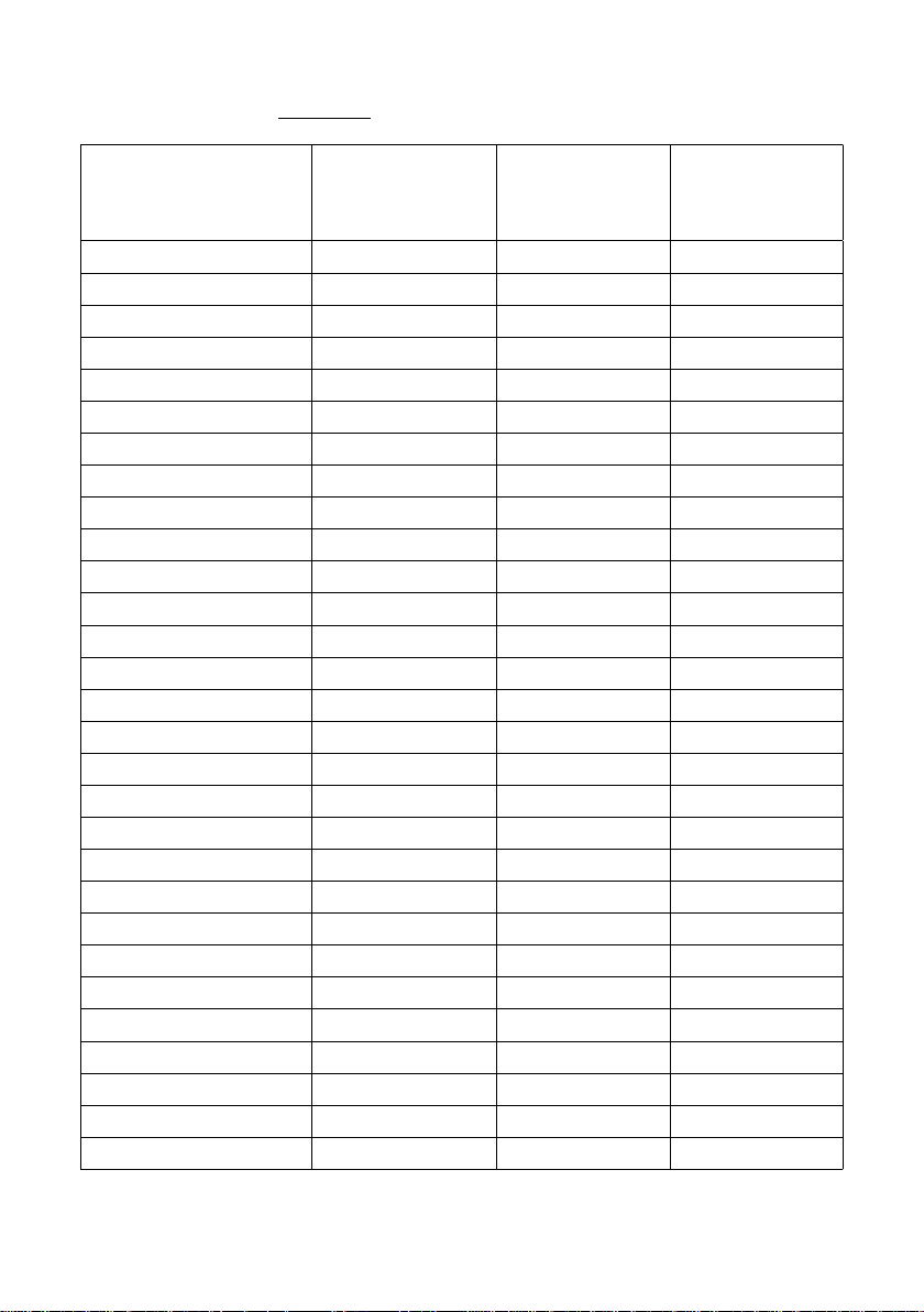
Fig. 10 – table of parameters
number
factory
values of values of
of parameter
values
application application
A
10 Amplitude 32.0 %
11 Frequency 50.0 Hz
12 Delay ON 00.0 s
13 Delay OFF 00.0 s
14 Ramp up/dwn 02.0 s
15 Batch ON 00.0 s
16 Batch pause 00.0 s
17 Ampl. MAX 100.0 %
18 Ampl. MIN 05.0 %
19 Input IN1 not used
20 Sensor 1 type normal open
21 Input IN2 not used
22 Sensor 2 type normal open
23 Analogue AIN not used
24 Output OUT1 not used
25 Timer T11 00.0 s
26 Timer T12 00.0 s
27 Timer T13 000 s
28 Output OUT2 not used
29 Timer T21 00.0 s
30 Timer T22 00.0 s
31 Timer T23 000 s
34 Wave type full wave
36 Switch ON press button
37 Service fnc not used
38 Lock/unlock
39 Language english
40 Info www.skipala.cz
41 Password
21/23
Page 22

9. Maintenance
The controller does not require any special
maintenance. Carry out Pergorm only regular inspection
in accordance with ČSN EN50110-1 ed.3 and Regulation
No. 50/78 Sb. In the case of failure do not repair send the controller to the manufacturer for repair. When
changing the fuse, observe the prescribed T8A value.
Tip for you: In the case of complications with the
operation of the controller, reset the factory setting
of the parameters (Chapter 8.29.).
10. Disposal
At the end of its service life the controller must be
handed over for professional disposal to a specialized
firm or the manufacturer.
11. Guarantee
The guarantee for the product is 12 months from the
day of sale.
Serial number:
Seller: Date of sale:
22/23
Page 23
12. ES DECLARATION OF CONFORMITY
In accordance with Act No. 90/2016 Coll. on conformity
assessment of specified products when they are placed on
the market, as amended.
Manufacturer: Skipala s.r.o.
Rybnik 162, 560 02 Rybnik
Czech Republic
Id. No.: 06607551
http://www.skipala.cz
Identification of the product:
Name: Digital controller for vibratory feeders
Model: DIGR-1502/E
We declare that the above-mentioned product fulfils
the respective provisions of the following EU
regulations:
Government Directive No. 118/2016 Coll. (Directive of
the European Parliament and the Council 2014/35/EU)
Government Directive No. 117/2016 Coll. (Directive of
the European Parliament and the Council 2014/30/EU)
Description of the product: The product is designed
for regulating vibration feeders driven by an
electromagnetic coil.
List of technical and harmonized standards used:
ČSN EN 61010-1 ed.2:11, ČSN EN 61326-1 ed.2:13,
ČSN EN 61000-6-2 ed.3:06, ČSN EN 61000-6-4 ed.2:07+A1:11
Source materials for issuing the EC Declaration of
Conformity: Certificate No. 1180684 issued on
October 15, 2018 by the Electrotechnical testing
institute on the basis of meeting the requirements of
the "EZÚ certificate" certification scheme.
The two last digits of the year in which the CE
indication was attached to the product: 18
In Rybnik on October 31, 2018 Karel Skipala
CEO
23/23
Page 24

 Loading...