

Page 1
SKIL Europe BV - Konijnenberg 60 7/04 2610393598
4825 BD Breda - The Netherlands
ROUTER
1830 (F0151830 . . )
www.skileurope.com
www.skileurope.com
INSTRUCTIONS page 7
INSTRUCTIONS page 9
HINWEISE Seite 13
INSTRUCTIES bladz. 16
INSTRUKTIONER sida 20
INSTRUKTION side 23
ANVISNING side 26
OHJEET sivu 29
INSTRUCCIONES pág. 32
INSTRUÇÕES pág. 35
ISTRUZIONI pag. 38
LEÍRÁS oldal 42
POKYNY strana 45
KILAVUZ sayfa 48
INSTRUKCJA strona 52
ИНСТРУКЦИИ страница 55
ІНСТРУКЦІЯ страница 59
O∆ΗΓΙΕΣ σελιδα 63
INSTRUCØIUNI pagina 67
YKA3AНИЕ страница 70
POKYNY strana 74
UPUTE stranica 77
UPUTSTVA stranica 81
NAVODILA stran 84
KASUTUSJUHEND lehekülg 87
INSTRUKCJIA lappuse 90
INSTRUKCJIA puslapis 94
GB
F
D
NL
S
DK
N
FIN
E
P
I
H
CZ
TR
PL
RU
UA
GR
RO
BG
SK
HR
SCG
SLO
EST
LV
LT
Page 2
3
2
1100 W
3,1 kg
1
6 mm
2
8 mm
4
1830
E
F
G
T
T
A
B
M
H
10 mm
7 mm
17 mm
z
4 mm
11 mm
x
y
not included
C
Page 3
3
5
ø
hard
soft
6
4 - 10 mm 5 - 6
12 - 20 mm 3 - 4
22 - 40 mm 1 - 2
4 - 10 mm 5 - 6
12 - 20 mm 3 - 6
22 - 40 mm 1 - 3
4 - 10 mm 3 - 6
12 - 20 mm 2 - 4
22 - 40 mm 1 - 3
4 - 15 mm 2 - 3
16 - 40 mm 1 - 2
4 - 15 mm 1 - 2
16 - 40 mm 1
J
Page 4
4
7
K
8
9 0
L
N
M
Page 5

5
!
@
S
V
W
E
G
XYZ
Page 6

6
#
SKIL nr.
2610392460
ACCESSORIES
$
%
d
L
B
D
d
8
mm
=
D
6,35
mm
=
B
19
mm
=
L
29
mm
=
d
L
B
D
d
8
mm
=
D
12,7
mm
=
B
12
mm
=
L
29
mm
=
d
L
B
D
d
D
B
L
=
=
=
=
12,7
10
29
8
mm
mm
mm
mm
B
d
L
D
=
d
8
=
D
22,2
=
B
10,5
=
L
29
=
R
6,35
R
mm
mm
mm
mm
mm
d
L
B
D
d
8
mm
=
D
12,7
mm
=
B
12,7
mm
=
L
29
mm
=
L
B
d
D
d
8
mm
=
D
25,4
mm
=
B
12,6
mm
=
L
29
mm
=
Page 7

Router 1830
INTRODUCTION
● The tool is intended to route grooves, edges, profiles and
elongated holes in wood, plastic and light building
materials as well as to copy-route
● Read and save this instruction manual
TECHNICAL SPECIFICATIONS 1
SAFETY
GENERAL SAFETY INSTRUCTIONS
WARNING! Read all instructions. Failure to follow all
instructions listed below may result in electric shock, fire
and/or serious injury. The term "power tool" in all of the
warnings listed below refers to your mains operated
(corded) power tool.
1) WORK AREA
a) Keep work area clean and well lit. Cluttered and dark
areas invite accidents.
b) Do not operate power tools in explosive
atmospheres, such as in the presence of flammable
liquids, gases or dust. Power tools create sparks which
may ignite the dust or fumes.
c) Keep children and bystanders away while operating
a power tool. Distractions can cause you to lose control.
2) ELECTRICAL SAFETY
a) Power tool plugs must match the outlet. Never
modify the plug in any way. Do not use any adapter
plugs with earthed (grounded) power tools.
Unmodified plugs and matching outlets will reduce risk of
electric shock.
b) Avoid body contact with earthed or grounded
surfaces such as pipes, radiators, ranges and
refrigerators. There is an increased risk of electric
shock if your body is earthed or grounded.
c) Do not expose power tools to rain or wet conditions.
Water entering a power tool will increase the risk of
electric shock.
d) Do not abuse the cord. Never use the cord for
carrying, pulling or unplugging the power tool. Keep
cord away from heat, oil, sharp edges or moving
parts. Damaged or entangled cords increase the risk of
electric shock.
e) When operating a power tool outdoors, use an
extension cord suitable for outdoor use. Use of a
cord suitable for outdoor use reduces the risk of electric
shock.
3) PERSONAL SAFETY
a) Stay alert, watch what you are doing and use
common sense when operating a power tool. Do not
use a power tool while you are tired or under the
influence of drugs, alcohol or medication. A moment
of inattention while operating power tools may result in
serious personal injury.
b) Use safety equipment. Always wear eye protection.
Safety equipment such as dust mask, non-skid safety
shoes, hard hat, or hearing protection used for
appropriate conditions will reduce personal injuries.
c) Avoid accidental starting. Ensure the switch is in the
off position before plugging in. Carrying power tools
with your finger on the switch or plugging in power tools
that have the switch on invites accidents.
d) Remove any adjusting key or wrench before turning
the power tool on. A wrench or a key left attached to a
rotating part of the power tool may result in personal
injury.
e) Do not overreach. Keep proper footing and balance
at all times. This enables better control of the power tool
in unexpected situations.
f) Dress properly. Do not wear loose clothing or
jewellery. Keep your hair, clothing and gloves away
from moving parts. Loose clothes, jewellery or long hair
can be caught in moving parts.
g) If devices are provided for the connection of dust
extraction and collection facilities, ensure these are
connected and properly used. Use of these devices
can reduce dust related hazards.
4) POWER TOOL USE AND CARE
a) Do not force the power tool. Use the correct power
tool for your application. The correct power tool will do
the job better and safer at the rate for which it was
designed.
b) Do not use the power tool if the switch does not turn
it on and off. Any power tool that cannot be controlled
with the switch is dangerous and must be repaired.
c) Disconnect the plug from the power source before
making any adjustments, changing accessories, or
storing power tools. Such preventive safety measures
reduce the risk of starting the power tool accidentally.
d) Store idle power tools out of the reach of children
and do not allow persons unfamiliar with the power
tool or these instructions to operate the power tool.
Power tools are dangerous in the hands of untrained
users.
e) Maintain power tools. Check for misalignment or
binding of moving parts, breakage of parts and any
other condition that may affect the power tools
operation. If damaged, have the power tool repaired
before use. Many accidents are caused by poorly
maintained power tools.
f) Keep cutting tools sharp and clean. Properly
maintained cutting tools with sharp cutting edges are
less likely to bind and are easier to control.
g) Use the power tool, accessories and tool bits etc., in
accordance with these instructions and in the
manner intended for the particular type of power
tool, taking into account the working conditions and
the work to be performed. Use of the power tool for
operations different from those intended could result in a
hazardous situation.
5) SERVICE
a) Have your power tool serviced by a qualified repair
person using only identical replacement parts. This
will ensure that the safety of the power tool is
maintained.
GB
7
Page 8

SAFETY INSTRUCTIONS FOR ROUTERS
GENERAL
● This tool should not be used by people under the age of
16 years
● Always disconnect plug from power source before
making any adjustment or changing any accessory
ACCESSORIES
● SKIL can assure flawless functioning of the tool only
when original accessories are used
● Use only accessories with an allowable speed matching
at least the highest no-load speed of the tool
● Do not use damaged or deformed router bits
● Only use sharp router bits
● Protect accessories from impact, shock and grease
● Only use high speed steel (HSS) or carbide-tipped (CT)
router bits with this tool
BEFORE USE
● Avoid damage that can be caused by screws, nails and
other elements in your workpiece; remove them before
you start working
● Always check that the supply voltage is the same as the
voltage indicated on the nameplate of the tool (tools with
a rating of 230V or 240V can also be connected to a
220V supply)
● Do not work with materials containing asbestos
● Clamp the workpiece in case it does not remain
stationary from its own weight
● Do not clamp the tool in a vice
● Use completely unrolled and safe extension cords with a
capacity of 16 Amps (UK 13 Amps)
● The noise level when working can exceed 85 dB(A);
wear ear protection
● Wear a dust protection mask when working with
materials which produce dust that is detrimental to
health; inform yourself beforehand about the materials to
be worked on
● Be sure tool is switched off when plugging in
DURING USE
● Always keep the cord away from moving parts of the
tool; direct the cord to the rear, away from the tool
● Never use tool when cord or base-plate M 2
(=protective guard) is damaged; have it replaced by a
qualified person
● Keep hands and fingers away from router bit when tool is
switched on
● Never exceed maximum cutting depth of router bit
(= B $) while cutting
● In case of electrical or mechanical malfunction,
immediately switch off the tool and disconnect the plug
● In case the router bit is blocked, resulting in jerking
forces on the tool, immediately switch off the tool
● In case of current interruption or when the plug is
accidentally pulled out, immediately switch off the tool in
order to prevent uncontrolled restarting
● Do not apply so much pressure on the tool that it comes
to a standstill
AFTER USE
● After finishing the work, lift lever E 2, guide the tool back
into the upper starting position, and switch off the tool
WHEN CONNECTING NEW 3-PIN PLUG (U.K. ONLY):
● Do not connect the blue (= neutral) or brown (= live) wire
in the cord of this tool to the earth terminal of the plug
● If for any reason the old plug is cut off the cord of this
tool, it must be disposed of safely and not left unattended
USE
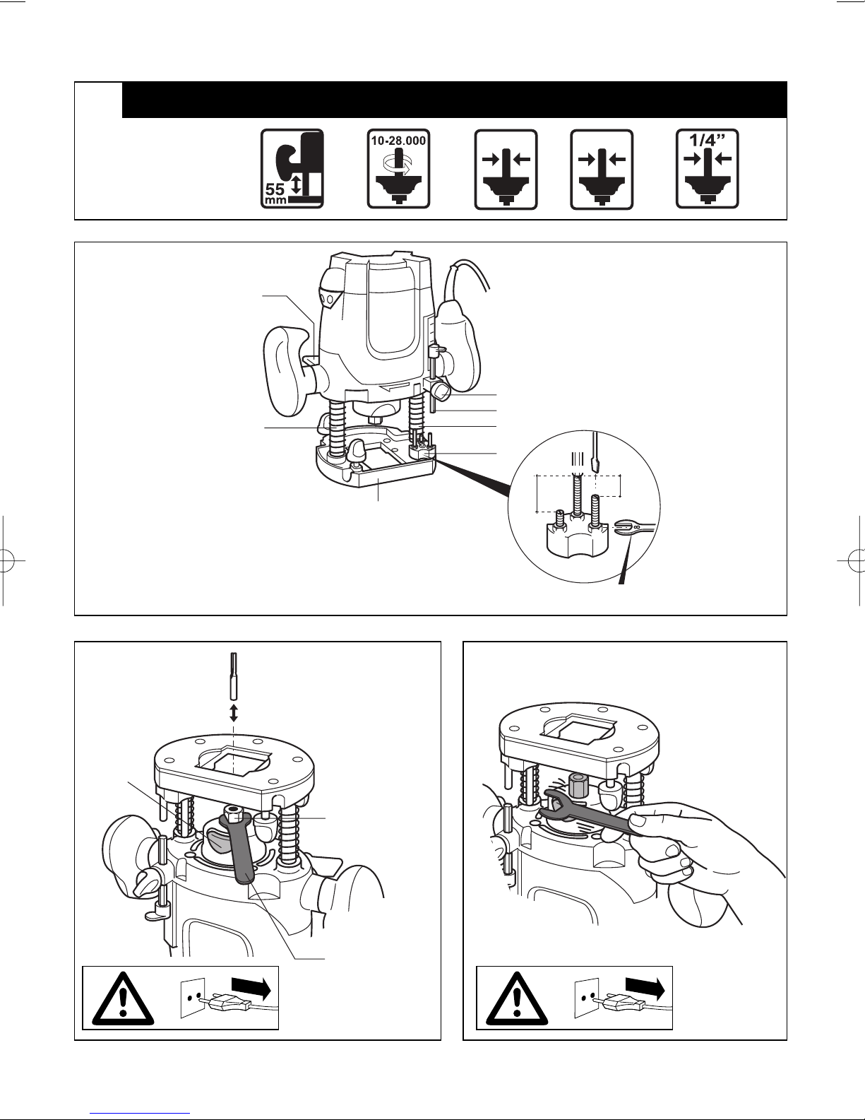
● Mounting/removing router bits 3
! switch off the tool and disconnect the plug
! ensure that router bit shaft is perfectly clean
! ensure that collet size (6 mm, 8 mm, 1/4”)
corresponds with shaft size of router bit
- turn tool upside down
- lock shaft by pushing shaft lock A (rotate collet nut B,
if necessary) and hold it while you
FOR MOUNTING:
- loosen collet nut B with wrench C
- insert bit 3/4 in collet
- tighten collet nut firmly with wrench C
FOR REMOVING:
- loosen collet nut B with wrench C
- remove bit
- release shaft lock A
!for loosening router bit it may be necessary to tap
collet nut with wrench 4
! never tighten collet nut, if there is no router bit in
collet; collet may be damaged
● Changing collet
! switch off the tool and disconnect the plug
! ensure that collet shaft is perfectly clean
- loosen collet nut B 2 or 3 turns
- tap collet nut B with wrench C
- remove collet nut B and collet (lock shaft)
- turn tool upside down
- insert new collet in collet shaft
- mount collet nut B (lock shaft)
! never tighten collet nut, if there is no router bit in
collet; collet may be damaged
● Adjusting routing depth/depth stop turret 2
EXAMPLE
Desired routing depths 7 mm (X), 11 mm (Y) and
17 mm (Z)
STEP 1:
- lift lever E
- loosen knob F so that depth gauge G moves freely
- push tool down until router bit is in contact with
workpiece
- push lever E back
- rotate turret H so that depth stop X clicks into place
right under depth gauge G
- note value as indicated on depth scale (e.g. 35 mm)
(for zeroing)
STEP 2:
- define difference among desired routing depths; use
lowest routing depth as reference (∆ X->Y = 4 mm;
∆ X->Z = 10 mm)
- rotate turret H so that depth stop Z clicks into place
right under depth gauge G
8
Page 9

- adjust depth stop Z (loosen nut, turn screw so that
depth gauge G reaches value noted minus 10 mm =
25 mm, tighten nut firmly)
- rotate turret H so that depth stop Y clicks into place
right under depth gauge G
- adjust depth stop Y (loosen nut, turn screw so that
depth gauge G reaches value noted minus 4 mm =
31 mm, tighten nut firmly)
- rotate turret H so that depth stop X clicks into place
right under depth gauge G
STEP 3:
- raise depth gauge G to desired routing depth plus
value noted earlier (7 + 35 = 42 mm)
- tighten knob F
- lift lever E
When repeated successive cuts at different depths are
not required, skip step 2
!always check the adjusted routing depth on a
piece of scrap wood
● Speed control 5
For optimal routing results on different materials
- select routing speed with wheel J (also while tool is
running)
- use table 6 as reference for determining the right
routing speed
- before starting a job, find the optimal speed by testing
out on spare material
! after longer periods of working at low speed, allow
the tool to cool down by running it for
approximately 3 minutes at high speed with no
load
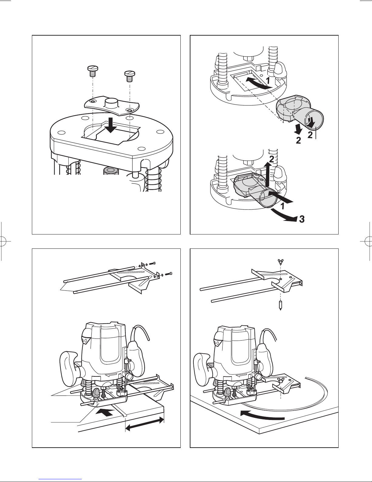
● Mounting adapter plate (for copying with a template) 7
● Mounting/removing of vacuum cleaner adapter K 8
● Mounting rip fence 9
- assemble rip fence as illustrated
- insert rip fence rods L through holes in base-plate M
- slide rip fence to desired width and fasten it with
2 knobs N
● Using the rip fence as a circular guide 0
! reverse rip fence first
- fasten pin P with wing nut Q as illustrated
- insert rods L into base-plate M
- pierce pin P into marked centre of circular arc
- fasten rip fence with 2 knobs N
- guide the tool with consistent feed across the
workpiece
● Using the rip fence with curve buffer R !
- mount curve buffer R (with guide roller mounted) as
illustrated
- insert rods L into base-plate M
- slide rip fence to desired width and fasten it with
2 knobs N
- guide the tool along the workpiece edge with light
sideward pressure
● Operating the tool @
- adjust routing depth
! always hold the tool firmly with both hands
- place tool on workpiece
- switch on tool by first pressing knob V (= safety switch
which cannot be locked) and then pulling trigger W
! before the router bit reaches the workpiece, the
tool should run at full speed
- lift lever E and slowly push tool down until depth
gauge G reaches depth stop X/Y/Z
- push lever E back
- carry out the routing procedure with uniform feed rate
- use the tool with its base-plate flat on the workpiece
- as a general rule one should pull the tool, not push it
- after finishing the work, lift lever E and guide the tool
back into the upper starting position
- switch off the tool by releasing trigger W
● Proper guiding #
- keep in mind that router bit turns clockwise
- guide tool so that bit turns into the workpiece, not
away from it
APPLICATION ADVICE
● Use the appropriate router bits $
● For cuts parallel with the side of your workpiece use rip
fence
● For making parallel cuts in a workpiece far from the
edge @
- fasten a straight piece of wood on the workpiece by
means of 2 clamps
- guide tool with base-plate along edge of wood which
now functions as a rip fence
● When using bits with a pilot or ball bearing, the pilot or
ball bearing should slide along the edge of the workpiece
which should be perfectly smooth %
● For larger routing depths, it is recommended to carry out
several repetitive cuts with lower removal rates
GUARANTEE / ENVIRONMENT
● Always keep tool and cord clean (especially the
ventilation slots S @)
!disconnect the plug before cleaning
● Lubricate sliding bars T 2 occasionally
● This SKIL product is guaranteed in accordance with
statutory/country-specific regulations; damage due to
normal wear and tear, overload or improper handling will
be excluded from the guarantee
● In case of a complaint, send the tool undismantled
together with proof of purchase to your dealer or the
nearest SKIL service station (addresses as well as the
service diagram of the tool are listed on
www.skileurope.com)
● Dispose of the tool by sorting tool, accessories and
packaging for environment-friendly recycling (the plastic
components are labeled for categorized recycling)
Défonceuse 1830
INTRODUCTION
● L’outil est conçu pour le fraisage des rainures, bords,
profils et rainures droites dans le bois, les matières
plastiques et matériaux de construction légers ainsi que
pour le fraisage par copiage
● Lisez et conservez ce manuel d'instructions
F
9
Page 10

98
CE DECLARATION OF CONFORMITY We declare under our sole responsibility that this product is in conformity with the following
standards or standardized documents: EN 60 745, EN 55 014, in accordance with the provisions of the directives 73/23/EEC,
89/336/EEC, 98/37/EEC.
NOISE/VIBRATION Measured in accordance with EN 60 745 the sound pressure level of this tool is 91 dB(A) and the sound power
level 102 dB(A) (standard deviation: 3 dB), and the vibration < 2.5 m/s
2
(hand-arm method).
CE DÉCLARATION DE CONFORMITÉ Nous déclarons sous notre propre responsabilité que ce produit est en conformité avec les
normes ou documents normalisés suivants: EN 60 745, EN 55 014, conforme aux réglementations 73/23/EEC, 89/336/EEC,
98/37/EEC. BRUIT/VIBRATION Mesuré selon EN 60 745 le niveau de la pression sonore de cet outil est 91 dB(A) et le niveau de la
puissance sonore 102 dB(A) (déviation standard: 3 dB), et la vibration < 2,5 m/s
2
(méthode main-bras).
CE KONFORMITÄTSERKLÄRUNG Wir erklären in alleiniger Verantwortung, daß dieses Produkt mit den folgenden Normen oder
normativen Dokumenten übereinstimmt: EN 60 745, EN 55 014, gemäß den Bestimmungen der Richtlinien 73/23/EWG,
89/336/EWG, 98/37/EWG.
GERÄUSCH/VIBRATION Gemessen gemäß EN 60 745 beträgt der Schalldruckpegel dieses Gerätes 91 dB(A) und der
Schalleistungspegel 102 dB(A) (Standard- abweichung: 3 dB), und die Vibration < 2,5 m/s
2
(Hand-Arm Methode).
CE CONFORMITEITSVERKLARING Wij verklaren, dat dit product voldoet aan de volgende normen of normatieve documenten:
EN 60 745, EN 55 014, overeenkomstig de bepalingen van de richtlijnen 73/23/EEG, 89/336/EEG, 98/37/EEG.
GELUID/VIBRATIE Gemeten volgens EN 60 745 bedraagt het geluidsdrukniveau van deze machine 91 dB(A) en het
geluidsvermogen-niveau 102 dB(A) (standaard deviatie: 3 dB), en de vibratie < 2,5 m/s
2
(hand-arm methode).
CE KONFORMITETSFÖRKLARING Vi intygar och ansvarar för, att denna produkt överensstämmer med följande norm och
dokument: EN 60 745, EN 55 014, enl. bestämmelser och riktlinjema 73/23/EWG, 89/336/EWG, 98/37/EWG.
LJUD/VIBRATION Ljudtrycksnivån som uppmätts enligt EN 60 745 är på denna maskin 91 dB(A) och ljudeffektnivån 102 dB(A)
(standard deviation: 3 dB), och vibration < 2,5 m/s2(hand-arm metod).
CE KONFORMITETSERKLÆRING Vi erklærer under almindeligt ansvar, at dette produkt er i overensstemmelse med følgende
normer eller normative dokumenter: EN 60 745, EN 55 014, i henhold til bestemmelserne i direktiverne 73/23/EØF, 89/336/EØF,
98/37/EØF. STØJ/VIBRATION Måles efter EN 60 745 er lydtrykniveau af dette værktøj 91 dB(A) og lydeffektniveau 102 dB(A)
(standard deviation: 3 dB), og vibrationsniveauet < 2,5 m/s
2
(hånd-arm metoden).
CE SAMSVARSERKLÆRING Vi erklærer at det er under vårt ansvar at dette produkt er i samsvar med følgende standarder eller
standard- dokumenter: EN 60 745, EN 55 014, i samsvar med reguleringer 73/23/EWG, 89/336/EWG, 98/37/EWG.
STØY/VIBRASJON Målt ifølge EN 60 745 er lydtrykknivået av dette verktøyet 91 dB(A) og lydstyrkenivået 102 dB(A) (standard
deviasjon: 3 dB), og vibrasjonsnivået < 2,5 m/s
2
(hånd-arm metode).
CE TODISTUS STANDARDINMUKAISUUDESTA Todistamme täten ja vastaamme yksin siitä, että tämä tuote en allalueteltujen
standardien ja standardoimisasiakirjojen vaatimusten mukainen EN 60 745, EN 55 014, seuraavien sääntöjen mukaisesti
73/23/EWG, 89/336/EWG, 98/37/EWG. MELU/TÄRINÄ Mitattuna EN 60 745 mukaan työkalun melutaso on 91 dB(A) ja yleensä
työkalun äänen voimakkuus on 102 dB(A) (keskihajonta: 3 dB), ja tärinän voimakkuus < 2,5 m/s
2
(käsi-käsivarsi metodi).
CE DECLARACION DE CONFORMIDAD Declaramos bajo nuestra sola responsabilidad que este producto está en conformidad
con las normas o documentos normalizados siguientes: EN 60 745, EN 55 014, de acuerdo con las regulaciones 73/23/CEE,
89/336/CEE, 98/37/CEE.
RUIDOS/VIBRACIONES Medido según EN 60 745 el nivel de la presión acústica de esta herramienta se eleva a 91 dB(A) y el nivel
de la potencia acústica 102 dB(A) (desviación estándar: 3 dB), y la vibración a < 2,5 m/s
2
(método brazo-mano).
CE DECLARAÇÃO DE CONFIRMIDADE Declaramos sob nossa exclusiva responsabilidade que este producto cumpre as
seguintes normas ou documentos normativos: EN 60 745, EN 55 014, conforme as disposições das directivas 73/23/CEE,
89/336/CEE, 98/37/CEE. RUÍDO/VIBRAÇÕES Medido segundo EN 60 745 o nível de pressão acústica desta ferramenta é 91 dB(A)
e o nível de potência acústica 102 dB(A) (espaço de erro: 3 dB), e a vibração < 2,5 m/s
2
(método braço-mão).
GB
F
D
NL
S
DK
N
FIN
E
P
04 SKIL Europe B.V. A. v.d. Kloot
CE DICHIARAZIONE DI CONFORMITÀ Dichiaramo, assumendo la piena responsabilità di tale dichiarazione, che il prodotto è
conforme alle seguenti normative e ai relativi documenti: EN 60 745, EN 55 014 in base alle prescrizioni delle direttive CEE 73/23,
CEE 89/336, CEE 98/37.
RUMOROSITÀ/VIBRAZIONE Misurato in conformità al EN 60 745 il livello di pressione acustica di questo utensile è 91 dB(A) ed il
livello di potenza acustica 102 dB(A) (deviazione standard: 3 dB), e la vibrazione < 2,5 m/s
2
(metodo mano-braccio).
I
CE MINÖSÉGI TANUSITVANY Teljes felelösségünk tudatában kijelentjük, hogy jelen termék a következö szabványoknak vagy
kötelezö hatósági elöírásoknak megfelel: EN 60 745, EN 55 014, a 73/23/EWG, 89/336/EWG, 98/37/EWG elöírásoknak megfelelöen.
ZAJ/REZGÉS Az EN 60 745 alapján végzett mérések szerint ezen készülék hangnyomás szintje 91 dB(A) a hangteljesítmény szintje
102 dB(A) (normál eltérés: 3 dB), a kézre ható rezgésszám < 2,5 m/s
2
.
H
CE STRVZUJÍCÍ PROHLÅ◊ENÍ Potvrzujeme na odpovπdnost, Ωe tento v¥robek odpovídå nåsledujícím normåm nebo normativním
podkladüm: EN 60 745, EN 55 014, podle ustanovení smπrnic 73/23/EWG, 89/336/EWG, 98/37/EWG.
HLUÇNOSTI/VIBRACÍ Mπ®eno podle EN 60 745 çiní tlak hlukové vlny tohoto p®ístroje 91 dB(A) a dávka hluçnosti 102 dB(A)
(standardní odchylka: 3 dB), a vibrací < 2,5 m/s
2
(metoda ruka-paΩe).
CZ
CE STANDARDIZASYON BEYANI Ye¤ane sorumlu olarak, bu ürünün afla¤ıdaki standartlara veya standart belgelerine uygun
oldu¤unu beyan ederiz: EN 60 745, EN 55 014, yönetmeli¤i hükümleri uyarınca 73/23/AET, 89/336/AET, 98/37/AET.
GÜRÜLTÜ//T‹TREfiIM Ölçülen EN 60 745 göre ses basıncı bu makinanın seviyesi 91 dB(A) ve çal›flma s›ras›ndaki gürültü 102 dB(A)
(standart sapma: 3 dB), ve titreflim < 2,5 m/s
2
(el-kol metodu).
TR
Page 11

99
04 SKIL Europe B.V. A. v.d. Kloot
ЗАЯВЛЕНИЕ О СООТВЕТСТВИИ Мы с полной ответственностыо заявляем, что это изделие соответствует следующим
стандартам или стандартизованным документам: EN 60 745, EN 55 014, в соответсувии с инструкциями 73/23/EEC,
89/336/EEC, 98/37/EEC. ШУМНОСТИ/ВИБРАЦИИ При измерении в соответствии co стандартoм EN 60 745 уровень
звукового давления для этого инструмента составляет 91 дБ (A) и уровeнь звуковой мощности - 102 дБ (A) (стандартное
отклонение: 3 dB), и вибрации - < 2,5 м/с
2
(по методу для рук).
RU
CE ВІДПОВІДНІСТЬ Ми заявляємо, що відповідність даного продукту наступним стандартам і регулюючим документам
повністю нашою відповідальністю: EN 60 745, EN 55 014, відповідно до положень директив 73/23/EEC, 89/336/EEC, 98/37/EEC.
ШУМ/ВІБРАЦІЯ Зміряний відповідно до EN 60 745 рівень тиску звуку даного інструменту 91 дБ(А) i потужність звуку
102 дБ(А) (стандартне відхилення: 3 дБ), i вібрація < 2,5 м/с
2
(ручна методика).
UA
CE ∆ΗΛΩΣΗ ΣYMBATOTΗΤΑΣ ∆ηλούµε υπευθύνως "τι το προϊ"ν αυτ" είναι κατασκευασµένο σύµφωνα µε τους εξής
κανονισµούς ή κατασκευαστικές συστάσεις: EN 60 745, EN 55 014, κατά τις διατάξεις των κανονισµών της Κοινής Αγοράς
73/23/EEC, 89/336/EEC, 98/37/EEC. ΘΟΡYΒΟ/ΚΡΑ∆ΑΣΜΟYΣ Μετρηµένη σύµφωνα µε EN 60 745 η στάθµη ακουστικής
πίεσης αυτού του εργαλείου ανέρχεται σε 91 dB(A) και η στάθµη ηχητικής ισχύoς σε 102 dB(A) (κοινή απ"κλιση: 3 dB), και
ο κραδασµ"ς σε < 2,5 m/s
2
(µεθοδος χειρ"ς/βραχίονα).
GR
DECLARAØIE DE CONFORMITATE CE Declaråm pe proprie råspundere cå acest product este conform cu urmåtoarele standarde
sau documente standardizate: EN 60 745, EN 55 014, în conformitate cu regulile 73/23/EEC, 89/336/EEC, 98/37/EEC.
ZGOMOT/VIBRAØII Måsurat în conformitate cu EN 60 745 nivelul de presiune a sunetului generat de acest instrument este de
91 dB(A) iar nivelul de putere a sunetului 102 dB(A) (abaterea standard: 3 dB), iar nivelul vibraøiilor < 2,5 m/s
2
(metoda mînå - braø).
RO
CE ДЕKЛАPAЦИЯ ЗA CБOTВETCTBИE Декларираме на изцяло наша отговорност, че това изделие е съобразено със
следните стандарти или стандартизирани документи: EN 60 745, EN 55 014, в съответствие с нормативната уредба на
73/23/EEC, 89/336/EEC, 98/37/EEC.
ШУМ/ВИБPAЦИИ Измерено в съответствие с EN 60 745 нивото на звуково налягане на този инструмент е 91 dB(A) а
нивото на звукова мощност е 102 dB(A) (стандартно отклонение: 3 dB), а вибрациите са < 2,5 m/s
2
(метод ръка-рамо).
BG
CE IZJAVA O USKLA ĐENOSTI Izjavljujemo uz punu odgovornost da je ovaj proizvod usklađen sa slijedeçim normama i
normativnim dokumentima: EN 60 745, EN 55 014, prema odredbama smjernica 73/23/EWG, 89/336/EWG, 98/37/EWG.
BUCI/VIBRACIJAMA Mjereno prema EN 60 745, prag zvuãnog tlaka ovog elektriãnog alata iznosi 91 dB(A) a jakost zvuka
102 dB(A) (standardna devijacija: 3 dB), a vibracija < 2,5 m/s
2
(postupkom na ‰aci-ruci).
HR
CE IZJAVA O USKLA ĐENOSTI Pod punom odgovorno‰çu izjavljujemo da je ovaj proizvod usklađen sa sledeçim standardima ili
standardizovanim dokumentima: EN 60 745, EN 55 014, u skladu sa odredbama smernica 73/23/EEC, 89/336/EEC, 98/37/EEC.
BUKA/VIBRACIJE Mereno u skladu sa EN 60 745, nivo pritiska zvuka ovog alata iznosi 91 dB(A), a jaãina zvuka 102 dB(A)
(normalno odstupanje: 3 dB), a vibracija < 2,5 m/s
2
(mereno metodom na ‰aci-ruci).
SCG
IZJAVA O USTREZNOSTI CE Odgovorno izjavljamo, da je ta izdelek v skladu z naslednjimi standardi ali standardnimi dokumenti:
EN 60 745, EN 55 014, v skladu s predpisi navodil 73/23/EEC, 89/336/EEC, 98/37/EEC.
HRUP/VIBRACIJA Izmerjeno v skladu s predpisom EN 60 745 je raven zvoãnega pritiska za to orodje 91 dB(A) in jakosti zvoka
102 dB(A) (standarden odmik: 3 dB), in vibracija < 2,5 m/s
2
(metoda ‘dlan-roka’).
SLO
CE VASTAVUSDEKLARATSIOON Kinnitame ainuvastutajana, et see toode vastab järgmistele standarditele või
normdokumentidele: EN 60 745, EN 55 014 vastavalt direktiivide 73/23/EMÜ, 89/336/EMÜ, 98/37/EMÜ nõuetele.
MÜRA/VIBRATSIOON Vastavalt kooskõlas normiga EN 60 745 läbi viidud mõõtmistele on antud seadme helirõhk 91 dB(A) ja
helitugevus 102 dB(A) (standardkõrvalekalle: 3 dB), ja vibratsioon < 2,5 m/s
2
(käe-randme-meetod).
EST
CE DEKLARÅCIJA PAR ATBILST±BU EEK STANDARTIEM Mïs ar pilnu atbild¥bu pazi¿ojam, ka ‰is izstrÇdÇjums atbilst EEK
standartiem vai standartizÇcijas dokumentiem EN 60 745, EN 55 014 un ir saska¿Ç ar EEK direkt¥vÇm 73/23/EEC, 89/336/EEC,
98/37/EEC.
TROK·øA/VIBRÅCIJAS Saska¿Ç ar standartu EN 60 745 noteiktais instrumenta rad¥tÇ trok‰¿a ska¿as spiediena l¥menis ir 91 dB(A)
un ska¿as jaudas l¥menis ir 102 dB (A) (pie tipiskÇs izkliedes: 3 dB), un vibrÇcijas intensitÇte ir < 2,5 m/s
2
(strÇdÇjot rokas reÏ¥mÇ).
LV
CE KOKYBñS ATITIKTIES DEKLARACIJA Mes atsakingai parei‰kiame, kad ‰is gaminys atitinka tokius standartus ir
normatyvinius dokumentus: EN 60 745, EN 55 014 pagal EEB reglament˜ 73/23/EWG, 89/336/EWG, 98/37/EWG nuostatas.
TRIUK·MINGUMAS/VIBRACIJA ·io prietaiso triuk‰mingumas buvo i‰matuotas pagal EN 60 745 reikalavimus keliamo triuk‰mo
garso slògio lygis siekia 91 dB(A) ir akustinio galingumo lygis 102 dB(A) (standartinis nuokrypis: 3 dB), ir vibracijos pagreitis rankos
pla‰takos srityje tipiniu atveju yra maÏesnis, kaip < 2,5 m/s
2
.
LT
CE ДЕKЛАPAЦИЯ ЗA CБOTВETCTBИE Декларираме на изцяло наша отговорност, че това изделие е съобразено със
следните стандарти или стандартизирани документи: EN 60 745, EN 55 014, в съответствие с нормативната уредба на
73/23/EEC, 89/336/EEC, 98/37/EEC.
ШУМ/ВИБPAЦИИ Измерено в съответствие с EN 60 745 нивото на звуково налягане на този инструмент е 91 dB(A) а
нивото на звукова мощност е 102 dB(A) (стандартно отклонение: 3 dB), а вибрациите са < 2,5 m/s
2
(метод ръка-рамо).
SK
OÂWIADCZENIE ZGODNOÂCI CE Niniejszym oÊwiadczamy ponoszàc osobistà odpowiedzialnoÊç, ˝e produkt wykonany jest
zgodnie z nast´pujàcymi normami i dokumentami normalizujàcymi: EN 60 745, EN 55 014, z godnie z wytycznymi 73/23/EWG,
89/336/EWG, 98/37/EWG. HA¸ASU/WIBRACJE Pomiarów dokonano zgodnie z normà EN 60 745 ciÊnienie akustyczne narz´dzia
wynosi 91 dB(A) zaÊ poziom mocy akustycznej 102 dB(A) (poziom odchylenie: 3 dB), zaÊ wibracje < 2,5 m/s
2
(metoda d∏oƒ-r´ka).
PL
Page 12

 Loading...